National Technical Construction Test Agency Approval … · 2017-05-22 · rehabilitation of buried...
53
National Technical Approval Approval body for construction products and types of construction Construction Test Agency A public law institution jointly funded by the federal government and the federal states . Member of the EOTA, UEAtc and WFTAO Date: 4/4/2017 Reference No.: III 54-1.42.3-77/15 Approval number: Z-42.3-336 Period of validity from: Tuesday, January 31, 2017 to: Monday, January 31, 2022 Applicant: BKP Berolina Polyester GmbH & Co. KG Heidering 28 16727 Velten Subject of approval: "Berolina Liner" CIPP (cure-in-place pipe) lining system and "Berolina HF Liner” for the rehabilitation of buried (underground), damaged wastewater sewers with circular cross- sections in nominal sizes DN 150 to DN 1600 and ovular (“egg-shaped”) cross-sections in nominal sizes 200 mm/300 mm to 1200 mm/1800 mm The subject of the approval named above is herewith granted a national technical approval. This national technical approval contains 22 pages and 26 appendices. This national technical approval replaces national technical approval No. Z-42.3-336 dated Friday, September 25, 2015, revised by the notifications dated January 10, 2008 and May 9, 2011. Translation of the original German version, not approved by the Deutsches Institut für Bautechnik
-
Upload
nguyendiep -
Category
Documents
-
view
217 -
download
0
Transcript of National Technical Construction Test Agency Approval … · 2017-05-22 · rehabilitation of buried...

National Technical Approval
Approval body for construction products and types of construction Construction Test Agency A public law institution jointly funded by the federal government and the federal states . Member of the EOTA, UEAtc and WFTAO
Date: 4/4/2017
Reference No.: III 54-1.42.3-77/15
Approval number: Z-42.3-336
Period of validity from: Tuesday, January 31, 2017 to: Monday, January 31, 2022
Applicant: BKP Berolina Polyester GmbH & Co. KG Heidering 28 16727 Velten Subject of approval: "Berolina Liner" CIPP (cure-in-place pipe) lining system and "Berolina HF Liner” for the rehabilitation of buried (underground), damaged wastewater sewers with circular cross-sections in nominal sizes DN 150 to DN 1600 and ovular (“egg-shaped”) cross-sections in nominal sizes 200 mm/300 mm to 1200 mm/1800 mm The subject of the approval named above is herewith granted a national technical approval. This national technical approval contains 22 pages and 26 appendices. This national technical approval replaces national technical approval No. Z-42.3-336 dated Friday, September 25, 2015, revised by the notifications dated January 10, 2008 and May 9, 2011.
Transla
tion o
f the o
rigina
l Germ
an ve
rsion
, not
appro
ved b
y the
Deu
tsche
s Ins
titut fü
r Bau
techn
ik

National Technical Approval No. Z-42.3-336 Page 2 of 27 - April 14, 2017 I GENERAL PROVISIONS
1 The national technical approval verifies usability or applicability of the subject of the approval in line with the state building codes.
2 If the national technical approval sets requirements for special knowledge and experience of the people entrusted with the production of construction products and types according to the state regulations according to § 17 Para. 5 of the model building code, it must be noted that this knowledge and experience can also be substantiated by providing equivalent verifications issued by other member states of the European Union. This may also apply to verifications presented equivalent within the scope of the Agreement on the European Economic Area (EEA) or other bilateral agreements.
3 The national technical approval does not replace the statutory permits, consents and certificates specified for the implementation of construction projects.
4 The national technical approval is issued notwithstanding the rights of third parties, in particular their private industrial property rights.
5 The manufacturer and seller of the subject of the approval, notwithstanding further provisions in the "Special Provisions", must provide the user of the subject of the approval with copies of the national technical approval and point out that the national technical approval must be available at the place of use. The authorities involved must be provided with copies of the national technical approval on request.
6 Only copies of the complete national technical approval may be made. Publication of excerpts requires the consent of Deutsche Institut für Bautechnik. Texts and drawings of promotional literature may not contradict the national technical approval. Translations of the national technical approval must contain the note "Translation of the original German version not checked by the Deutsche Institut für Bautechnik".
7 The national technical approval issued may be cancelled. The provisions of the national technical approval can be subsequently added to and changed, especially if new technical knowledge requires this.
Transla
tion o
f the o
rigina
l Germ
an ve
rsion
, not
appro
ved b
y the
Deu
tsche
s Ins
titut fü
r Bau
techn
ik

National Technical Approval No. Z-42.3-336 Page 3 of 27 - April 14, 2017 II. SPECIAL PROVISIONS 1 Subject of approval and scope
This national technical approval applies to the "Berolina Liner" CIPP lining system (Appendix 1) and “Berolina HF Liner” (Appendix 2) using glass fiber reinforced plastic (GRP) tubes for the rehabilitation of damaged wastewater sewers with circular cross-sections in nominal sizes DN 150 to DN 1600 and ovular cross-sections with dimensions 200 mm/300 mm to 1200 mm/1800 mm and ratio approx. W:H = 2:3. This approval applies to the rehabilitation of sewers, which are mainly intended to drain domestic wastewater in accordance with DIN 1986-31.
The CIPP lining system can be used for the rehabilitation of sewers made of concrete, masonry, reinforced concrete, steel (not pressure pipes), vitrified clay, asbestos-free fiber cement, GRP, PVC-U, PE-HD and cast iron, provided the cross-section of the sewer to be rehabilitated satisfies the method-related requirements and structural requirements.
Damaged sewers are rehabilitated by inserting and subsequently UV curing a resin-impregnated seamless glass fiber tube. To this end, a smooth (slip) foil marked with PVC or PE stripes, possibly textile-reinforced, is pulled into the damaged pipe first as an installation aid. The resin-impregnated glass fiber tube with multi-layer foils on both sides is pulled over this and is inflated by applying compressed air.
Swelling tapes (auxiliary materials) must be placed between the existing pipe and before pulling in the PE or PVC smooth foil in the area of the manhole joint. In the areas in which swelling tapes (auxiliary tapes) cannot be used for construction reasons, the water-tight formation of the joint areas between the liner and manhole following curing of the liner can also be carried out as follows:
1. Butyl rubber adhesive tapes 2. Connection of the liner by means of reaction resin paste, for which a national technical
approval is valid, 3. Connection of the liner by means of mortar systems, for which a national technical
approval is valid, 4. GRP laminates, 5. Grouting with polyurethane (PU) or epoxy (EP) resins for which a national technical
approval is valid, 6. Installation of liner end sleeves for which a national technical approval is valid.
1 DIN 1986-3 Entwässerungsanlagen für Gebäude und Grundstücke - Teil 3: Regeln für Betrieb und Wartung; Ausgabe: 2004-11
Transla
tion o
f the o
rigina
l Germ
an ve
rsion
, not
appro
ved b
y the
Deu
tsche
s Ins
titut fü
r Bau
techn
ik

National Technical Approval No. Z-42.3-336 Page 4 of 27 - April 14, 2017 Lateral connections can be reinstated either by open construction method or by means of the rehabilitation method, for which national technical approvals are valid.
Transla
tion o
f the o
rigina
l Germ
an ve
rsion
, not
appro
ved b
y the
Deu
tsche
s Ins
titut fü
r Bau
techn
ik

National Technical Approval No. Z-42.3-336 Page 5 of 27 - April 14, 2017 2 Provisions for the Process Components 2.1 Properties and composition Where applicable, the liners named in Section 1 fulfill the requirements of EN ISO 11296-42, they have the specific properties and compositions listed in the following. 2.1.1 Materials for the process components in the “M” state 2.1.1.1 Tube materials The materials used for the outer styrene-tight and UV-protected PE/PA/PE composite foil with a minimum PA thickness of 40 μm (-5 μm + 10 ± μm) and for the inner multi-layer foil must correspond to the recipe details deposited with the Deutsche Institut für Bautechnik. Only resins and hardener components corresponding to the recipe details deposited with the Deutsche Institut für Bautechnik may be used to impregnate the glass fiber tubes. Only unsaturated polyester resins (UP resins to EN13121-13, table 1, group 3 Iso-Npg and Ortho-Npg) of the type 1140 to table 3 or vinyl ester resins (VE resins) of the type 1310 to table 4 of DIN 16946-24 may be used. The polyester and vinyl resins conform to the IR spectra deposited with the Deutsche Institut für Bautechnik. The IR spectra must also be deposited with the external monitoring body. Only corrosion-resistant glass fibers, e.g. E-CR glass fibers in the form of multiple arranged fabric and/or multi-ply and mats and/or multi-axial multi-plies, which conform to the requirements of EN 14020-145, EN 14020-26 and EN 14020-37 can be used.
2 EN ISO 11296-4 Plastics piping systems for renovation of underground non-pressure drainage and sewerage networks -- Part 4 Lining with cured-in-place pipes (ISO 11296-4:2009, corrected version 2010-06-01); German version EN ISO 11296-4:2011; issued: 2011-07 3EN 13121-1 GRP tanks and vessels for use above ground — Part 1: Raw materials. Specification conditions and acceptance conditions; German version EN 13121-1:2003; issued: 2003-10 4 DIN 16946-2 Reaktionsharzformstoffe; Gießharzformstoffe; Typen; Ausgabe: 1989-03 5 EN 14020-1 Reinforcements - Specification for textile glass rovings - Part 1: Designation; German version EN 14020-1:2002; Published: 2003-03 6 EN 14020-2 Reinforcements - Specifications for textile glass rovings - Part 2: Methods of test and general requirements; German version EN 14020-2:2002; Published: 2003-03 7 EN 14020-3 Reinforcements - Specification for textile glass rovings - Part 3: Specific requirements; German version EN 14020-3:2002; Published: 2003-03
Transla
tion o
f the o
rigina
l Germ
an ve
rsion
, not
appro
ved b
y the
Deu
tsche
s Ins
titut fü
r Bau
techn
ik

National Technical Approval No. Z-42.3-336 Page 6 of 27 - April 14, 2017 Only polyester non-wovens (PES non-wovens) corresponding to the recipe details deposited with the Deutsche Institut für Bautechnik can be used for reinforcement of the resin-impregnated inner layer facing the wastewater. 2.1.1.2 Materials for manhole connections a) Swelling tape (auxiliary material) (Appendix 20) Only extruded profiles, consisting of a chloroprene (CR/SBR) rubber and water-absorbing resin may be used for the swelling tape (auxiliary material) in the area of the manhole jointing of the tube liner. When stored in water, the swelling tapes must have a volume increase of at least 100 % after 72 h. Compliance of the swelling tapes with the geometric requirements (cross-section shape and dimensions) must be checked visually and by random re-measurement as part of the incoming inspection. b) Butyl rubber adhesive tape (Appendix 23) Only butyl-rubber based adhesive tapes, whose properties correspond to those of the recipe deposited with the Deutsche Institut für Bautechnik may be used for water-tight jointing in the area of the connection of the tube liner with the manhole. 2.1.2 Liner in the "I” state 2.1.2.1 Wall thicknesses and wall construction After the pulling in and curing, the "Berolina Liner" must have a wall build-up (construction) of at least four layers (Appendix 1) and the "Berolina HF Liner" a wall build-up of at least six layers (Appendix 2) made of textile glass, which are arranged under the outer multi-layer composite foil. The layers are made of textile glass fabric and/or textile glass multi-ply and textile glass mats, which are stitched to form complex or rather multi-axial multi-plies. Inside the "Berolina Liner" and the "Berolina HF Liner" must have, on the wastewater side, on the inner textile glass mat, a final layer of polyester nonwoven as a wear layer and a multi-layer composite foil (installation foil), which is removed from the GRP liner after it has cured. The nominal sizes and stiffness-based wall thicknesses are determined by the number and combinations of several complexes/multi-axial multi-plies. The wall thickness of the respective GRP liner is to be checked by way of a structural consideration according to leaflet DWA-A 143-28 (see also Section 9). If the host pipe-soil system alone is no longer load-bearing, such wastewater sewers may only
8 DWA-A 143-2 Deutsche Vereinigung für Wasserwirtschaft, Abwasser und Abfall e. V. (DWA) -Arbeitsblatt 143: Sanierung von Entwässerungssystemen außerhalb von Gebäuden -Teil 2: Statische Berechnungen zur Sanierung von Abwasserleitungen und -kanälen mit Lining- und Montageverfahren; Ausgabe: 2015-07
Transla
tion o
f the o
rigina
l Germ
an ve
rsion
, not
appro
ved b
y the
Deu
tsche
s Ins
titut fü
r Bau
techn
ik

National Technical Approval No. Z-42.3-336 Page 7 of 27 - April 14, 2017 be rehabilitated with the “Berolina Liner” with wall thicknesses listed in Appendix 3 and 4, and the “Berolina HF Liner” with wall thicknesses given in Appendices 5 and 6, if the structural loads to be carried by the tube liner are verified by structural calculation according to leaflet DWA-A 143-28. The short-term ring stiffnesses (2-minute values) of the cured GRP liner and the corresponding ... given in Appendices 3 to 6 for circular and ovular cross-sections (wall thicknesses depending on the short-term ring stiffness SR) must be complied with for the structural calculation. GRP liners with the nominal stiffnesses and wall thicknesses given in Appendices 3 to 6 (circular and ovular cross-sections) may be used for the rehabilitation of sewers, if the host pipe-soil system alone is load bearing (without support of the surrounding soil). If there are one or several continuous longitudinal cracks in the host pipe, soil investigations, e.g. by way of penetration tests, are required and appropriate verifying calculations must be performed. In the event of infiltrations, the GRP liner must be dimensioned with regard to its deformation and buckling behavior. In the system that is the subject of this national technical approval, resin-impregnated tube liners which have a minimum wall thickness of 3 mm after installation and curing are used for rehabilitation measures. Tube liners with a nominal stiffness SN >_ 500N/m2 to SN>_630N/m2 with corresponding wall thicknesses are also allowed. The following relationships apply to the nominal stiffness SN and short-term ring stiffness SR:
For SN: For SR:
(SN = nominal stiffness based on DIN 16869-29) (rm = gravity radius) 2.1.2.2 Dimensions of tube liners for ovular (egg-shaped) cross-sections The CIPP lining system can also essentially be used to rehabilitate damaged sewers with ovular cross-sections, which conform to the width and height dimensions and corresponding wall thicknesses given in Appendices 3 to 6. 2.1.2.3 Physical characteristics of the cured glass fiber resin composite Cured GRP liners (without multi-layer foil) must have the following properties: “Berolina Liner"
9 DIN 16869-2 Rohre aus glasfaserverstärktem Polyesterharz (UP-GF),geschleudert, gefüllt - Teil 2: Allgemeine Güteanforderungen, Prüfung; Ausgabe: 1995-12
Transla
tion o
f the o
rigina
l Germ
an ve
rsion
, not
appro
ved b
y the
Deu
tsche
s Ins
titut fü
r Bau
techn
ik
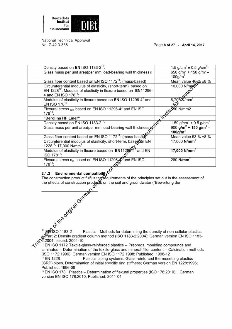
National Technical Approval No. Z-42.3-336 Page 8 of 27 - April 14, 2017 Density based on EN ISO 1183-210: 1.5 g/cm3 ± 0.5 g/cm3-Glass mass per unit area(per mm load-bearing wall thickness): 650 g/m2 + 150 g/m2 –
100g/m2 Glass fiber content based on EN ISO 117211: (mass-based) Mean value 46 % ±8 % Circumferential modulus of elasticity, (short-term), based on EN 122812: Modulus of elasticity in flexure based on EN11296-4 and EN ISO 17813:
10,000 N/mm2
Modulus of elasticity in flexure based on EN ISO 11296-42 and EN ISO 17813
8,700 N/mm2
Flexural stress Qra based on EN ISO 11296-42 and EN ISO 17813:
150 N/mm2
"Berolina HF Liner" Density based on EN ISO 1183-210: 1.59 g/cm3 ± 0.5 g/cm3
Glass mass per unit area(per mm load-bearing wall thickness): 900 g/m2 + 150 g/m2 – 100g/m2
Glass fiber content based on EN ISO 117211: (mass-based) Mean value 53 % ±8 % Circumferential modulus of elasticity, short-term, based on EN 122812: 17,000 N/mm2
17,000 N/mm2
Modulus of elasticity in flexure based on EN11296-42 and EN ISO 17813:
17,000 N/mm2
Flexural stress am based on EN ISO 11296-42 and EN ISO 17813:
280 N/mm2
2.1.3 Environmental compatibility The construction product fulfills the requirements of the principles set out in the assessment of the effects of construction products on the soil and groundwater ("Bewertung der
10 EN ISO 1183-2 Plastics - Methods for determining the density of non-cellular plastics —Part 2: Density gradient column method (ISO 1183-2:2004); German version EN ISO 1183-2:2004; issued: 2004-10 11 EN ISO 1172 Textile-glass-reinforced plastics -- Prepregs, moulding compounds and laminates -- Determination of the textile-glass and mineral-filler content -- Calcination methods (ISO 1172:1996); German version EN ISO 1172:1998; Published: 1998-12 12 EN 1228 Plastics piping systems. Glass-reinforced thermosetting plastics (GRP) pipes. Determination of initial specific ring stiffness; German version EN 1228:1996; Published: 1996-08 13 EN ISO 178 Plastics – Determination of flexural properties (ISO 178:2010); German version EN ISO 178:2010; Published: 2011-04
Transla
tion o
f the o
rigina
l Germ
an ve
rsion
, not
appro
ved b
y the
Deu
tsche
s Ins
titut fü
r Bau
techn
ik

National Technical Approval No. Z-42.3-336 Page 9 of 27 - April 14, 2017 Auswirkungen von Bauprodukten auf Boden und Grundwasser" (Version: 2011, Schriften des Deutschen Instituts für Bautechnik). This statement only applies to compliance with the special provisions of this national technical approval. The proviso of permit issued by the competent water authority, especially in water protection zones, remains unaffected. 2.2 Production, packaging, transport, storage and labeling 2.2.1 Mass production of the GRP liners The reaction resin is mixed with the additives by static mixers in the feed lines. The metering according to the recipe must be carried out by means of process controlled feed pumps. Compliance with the recipe must be monitored by means of flow measurement and continuous weight reduction in the container connected to the metering unit and must be recorded for each batch. The glass fiber sheets and foils with properties according to section 2.1.1.1 purchased from suppliers as reel goods must be continuously unwound over low-vibration and level-controlling rolls and fed onto a diameter-specific mandrel. Deflection clips adjusted to the liner diameter ensure the correct positioning and alignment of the sheets. The glass fiber sheets must be joined on the system, in compliance with the multi-layer wall construction according to section 2.1.2.1 so that at least the wall thicknesses given in Appendix 2 and 3 (circular and ovular cross-sections) are produced. When joining, ensure that the individual complexes overlap by approx. 10 %. The glass fiber tube is then welded in an outer foil according to section 2.1.1.1 so that a closed tube is produced. In a further step, the inner foil must be pulled through the mandrel by means of a pulling thread. In the vertical initial draw the closed tube must be impregnated with the mixed resin. To prevent resin from escaping, the ends of the tube liner must be sealed with foils and adhesive tapes before it is packed. Immediately after impregnation, the tube liners fitted with a styrene-tight foil must be placed in layers in transport packaging depending on the tube diameter and flat width. Ensure that intermediate packaging layers are used to spread the weight of the tube liner.
The relevant accident prevention and occupational health regulations must be complied with for factory production of the glass fiber tubes and the resin impregnation. In particular the technical regulations for hazardous materials, limit values in air (TRGS 90014 "Grenzwerte in der Luft") must be complied with regarding styrene. Ensure that suitable measures are taken (e.g. extraction equipment) to ensure the styrene limits are not exceeded.
14 TRGS 900 Technische Regeln für Gefahrstoffe - Grenzwerte der Luft am Arbeitsplatz "Luftgrenzwerte"; Ausgabe: 2006-01 mit Änderungen und Ergänzungen der Ausgaben 2008-06, 2009-07, 2010-02 und vom 21.06.2010
Transla
tion o
f the o
rigina
l Germ
an ve
rsion
, not
appro
ved b
y the
Deu
tsche
s Ins
titut fü
r Bau
techn
ik

National Technical Approval No. Z-42.3-336 Page 10 of 27 - April 14, 2017
Comply with the relevant accident prevention regulations and the implementing regulations of the law on hazardous substances (GefahrstoffVO) when handling the impregnated hoses. 2.2.2 Packaging, transport, storage
The resin delivered to the applicant's manufacturing plant for the factory production of tube liners can be stored in suitable storage tanks, in temperature-controlled storage rooms with a monitored temperature range of +5 °C to approx. +30 °C.
The GRP liners produced can be stored in the light and styrene-proof foils in the transport packaging for approx. 6 months at a temperature of +5 °C to +30 °C. The transport packaging must be protected against direct sunlight and heat sources.
The relevant accident prevention regulations must be complied with during storage and transport.
2.2.3 Labeling The transport containers of the GRP liners are to be labeled with the German compliance mark (Ü mark) according to the compliance mark regulations of the federal states (including the approval number Z-42.3-336). The labeling may only be carried out if the requirements according to section 2.3 are fulfilled. The manufacturer must be included on the containers, on the packaging, the enclosed leaflet or the delivery note, the hazard symbols and H and P statements in accordance with the hazardous substances regulations and EU Regulation No. 1907/2006 (REACH) and the respective current version of the CLP Regulation (EC) 1272/200815. The packagings must be marked according to the rules of the respective valid versions of the ADR16. In addition, the following information must be given:
Nominal size Wall thickness Tube length
Date of resin impregnation
Production site (place where resin impregnated)
Batch number
Storage temperature range
15 1272/2008 Regulation (EC) No. 1272/2008 on classification, labelling and packaging of substances and mixtures 16 ADR the European Agreement concerning the International Carriage of Dangerous Goods by Road (Accord europeen relatif au transport international des merchandises Dangereuses par Route)
Transla
tion o
f the o
rigina
l Germ
an ve
rsion
, not
appro
ved b
y the
Deu
tsche
s Ins
titut fü
r Bau
techn
ik
National Technical Approval No. Z-42.3-336 Page 11 of 27 - April 14, 2017
H and P statements in accordance with the hazardous substance regulations
Reference to light sensitivity 2.3 Compliance certificate 2.3.1 General information Compliance of the process components with the provisions of this national technical approval must be confirmed for each manufacturing plant with a compliance certificate on the basis of the factory production control and regular external monitoring, including initial testing of the process components according to the following provisions. For the issue of the compliance certificate and the external monitoring, including the product tests to be performed, the manufacturer who mixes the resin and impregnates the hoses, must involve a recognized certification body and a recognized monitoring body. The manufacturer must submit the declaration that a compliance certificate has been issued by labeling the construction products with the compliance mark (Ü mark) with reference to the intended use.
The certification body must give the Deutsche Institut für Bautechnik a copy of the compliance certificate it has issued, for information purposes.
The Deutsche Institut für Bautechnik must also be given a copy of the initial test report for information purposes.
2.3.2 Factory production control Factory production control must be set up and carried out in each manufacturing plant. Factory production control is the term used to describe the continuous production monitoring to be carried out by the manufacturer, with which they ensure that the construction products manufactured by them conform to the provisions of this national technical approval.
The factory production control should at least include the measures listed in the following:
1. Description of and checking of the starting (raw) material Tube liner materials With each delivery of the components: protective foils, glass fibers, polyester non-woven and
Transla
tion o
f the o
rigina
l Germ
an ve
rsion
, not
appro
ved b
y the
Deu
tsche
s Ins
titut fü
r Bau
techn
ik

National Technical Approval No. Z-42.3-336 Page 12 of 27 - April 14, 2017 resins, the applicant must convince themselves that the properties required according to section 2.1.1 are complied with. To this end, the applicant must ensure that the respective suppliers submit to them appropriate type 2.2 test reports based on EN 1020417. The following properties must be randomly checked as part of the incoming inspection:
Properties of the resin:
- Viscosity
- Reactivity
Properties of the glass fibers:
- Mass per unit area
- UV permeability In addition, the UV permeability of the multi-layer composite foils must be tested for each delivery.
1. Controls and tests to be carried out during production: The following parameters are to be monitored and recorded during production of the glass fiber tube and the resin impregnation:
Feed speed Compliance with the recipe (flow measurement of the resin and reduction in
weight of the additives) Uniformity of the resin impregnation Roll spacing Welding parameters (including welding temperature and uniformity of the
welded joints of the protective foils) Tube width and thickness Tube length Batch number
2. Verifications and tests to be carried out on the impregnated glass fiber tubes and cured
test pieces: a) Tests on the resin-impregnated glass fiber tubes:
17 EN 10204 Metallic products - types of inspection documents; German version EN 10204:2004; issued: 2005-01
Transla
tion o
f the o
rigina
l Germ
an ve
rsion
, not
appro
ved b
y the
Deu
tsche
s Ins
titut fü
r Bau
techn
ik

National Technical Approval No. Z-42.3-336 Page 13 of 27 - April 14, 2017 The widths of the resin-impregnated, not yet inflated tube liners given in the following table 1 (circular cross-sections) and table 2 (ovular cross-sections) must be checked: Table 1 "Liner widths for circular cross-sections (resin impregnated, not inflated) for the "Berolina Liner" and the "Berolina HF Liner"'
Nominal size DN
Tube liner width in mm
(+25 mm -15 mm)
Nominal size DN
Tube liner width in mm
(+25 mm -15 mm)
150 210 675 1,015
190 273 700 1,033
200 273 750 1,120
225 304 800 1,160
250 345 883 1,320
300 443 900 1,340
315 475 950 1,400
350 476 1,000 1,480
375 538 1,050 1,570
400 580 1,100 1,675
450 650 1,150 1,765
480 700 1,200 1,802
500 730 1,250 1,900
525 745 1,260 1,920
550 790 1,300 1,950
580 800 1,400 2,160
600 890 1,500 2,235
631 920 1,520 2,240
650 990 1,600 2,320
Table 2 "Liner widths for ovular cross-sections (resin impregnated, not inflated) for the "Berolina Liner" and the "Berolina HF Liner""
Width / Height mm/mm
Tube liner width in mm
(+25 mm -15 mm)
Width / Height mm/mm
Tube liner width in mm
(+25 mm -15 mm)
200 /300 345 700 / 1050 1,320
199 / 375 355 7501 / 1125 1,400
250 / 375 475 800 / 1200 1,480
300 / 475 538 840 / 1260 1,570
350 / 525 650 900 / 1350 1,765
Transla
tion o
f the o
rigina
l Germ
an ve
rsion
, not
appro
ved b
y the
Deu
tsche
s Ins
titut fü
r Bau
techn
ik

National Technical Approval No. Z-42.3-336 Page 14 of 27 - April 14, 2017
400 / 600 730 1000 / 1500 1,920
500 / 750 920 1100 / 1650 2,160
600 / 900 1,120 1200 / 1800 2,240
b) Tests on cured test pieces for production control: Within the scope of the factory production control, regular test specimens must be taken and tested for random checking of the liner quality. It is necessary to ensure that it is not exposed to uncontrolled UV radiation. The test specimen must be inflated to the respective nominal size in the applicant's laboratory, under the same criteria as those described in sections 4.3.8 to 4.3.11 (feed speed according to Appendix 17 and 18), by applying an internal pressure of at least 0.02 bar and cured using the UV lamps named in section 4.2.1.
As a minimum requirement, the following tests must at least be carried out on this specimen or the samples taken from it:
- Leak tightness of the laminate
The leak tightness of the cured GRP liner must be tested without foil coating according to section 7.2 based on EN 16101-8 (Appendix 25)- Density
The density is to be tested using the sample taken from the cured GRP liner without smooth foil and without foil coating, e.g. to EN ISO 1183-210. It must be determined whether the density of the cured GRP line given in section 2.1.2.3 is complied with. - Glass fiber content/resin content The glass fiber content and resin content are to be checked according to the specifications in section 2.1.2.3 to EN ISO 117211. - Wall thickness and wall construction: The average and complete wall thickness and the wall construction according to the conditions in section 2.1.2.1 are to be checked at cut surfaces, e.g. using a light microscope with approx. 10-fold magnification. At the same time, the thickness of the pure resin layer must also be checked. In addition, the average percentage area of the air bubbles must be tested to EN ISO 782218 (determination of void content).
18 EN ISO 7822 Textile glass reinforced plastics -- Determination of void content -- Loss on ignition, mechanical disintegration and statistical counting methods (ISO 7822:1990); German version of EN ISO 7822:1999; Published: 2000-01
Transla
tion o
f the o
rigina
l Germ
an ve
rsion
, not
appro
ved b
y the
Deu
tsche
s Ins
titut fü
r Bau
techn
ik
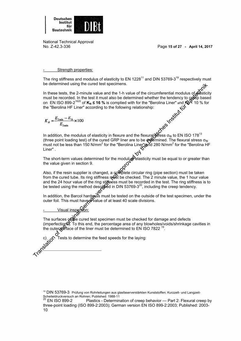
National Technical Approval No. Z-42.3-336 Page 15 of 27 - April 14, 2017 - Strength properties: The ring stiffness and modulus of elasticity to EN 122811 and DIN 53769-319 respectively must be determined using the cured test specimens. In these tests, the 2-minute value and the 1-h value of the circumferential modulus of elasticity must be recorded. In the test it must also be determined whether the tendency to creep based on EN ISO 899-21620 of KN ≤ 16 % is complied with for the "Berolina Liner" and KN < 10 % for the "Berolina HF Liner" according to the following relationship:
In addition, the modulus of elasticity in flexure and the flexural stress σfB to EN ISO 17813 (three point loading test) of the cured GRP liner are to be determined. The flexural stress σfB must not be less than 150 N/mm2 for the "Berolina Liner" and 280 N/mm2 for the "Berolina HF Liner" . The short-term values determined for the moduli of elasticity must be equal to or greater than the value given in section 9. Also, if the resin supplier is changed, a complete circular ring (pipe section) must be taken from the cured tube. Its ring stiffness must be checked. The 2 minute value, the 1 hour value and the 24 hour value of the ring stiffness must be recorded in the test. The ring stiffness is to be tested using the method described in DIN 53769-320, including the creep tendency. In addition, the Barcol hardness must be tested on the outside of the test specimen, under the outer foil. This must have a value of at least 40 scale divisions. - Visual inspection: The surfaces of the cured test specimen must be checked for damage and defects (imperfections). To this end, the percentage area of any blowholes/voids/shrinkage cavities in the outer surface of the liner must be determined to EN ISO 7822 19. c) Tests to determine the feed speeds for the laying:
19 DIN 53769-3 Prüfung von Rohrleitungen aus glasfaserverstärkten Kunststoffen; Kurzzelt- und Langzeit-Scheiteldruckversuch an Rohren; Published: 1988-11 20 EN ISO 899-2 Plastics - Determination of creep behavior — Part 2: Flexural creep by three-point loading (ISO 899-2:2003); German version EN ISO 899-2:2003; Published: 2003-10
Transla
tion o
f the o
rigina
l Germ
an ve
rsion
, not
appro
ved b
y the
Deu
tsche
s Ins
titut fü
r Bau
techn
ik

National Technical Approval No. Z-42.3-336 Page 16 of 27 - April 14, 2017 For the feed rates of the UV light trains not yet named in Appendix 17 and 18, the applicant must determine the feed speeds to be complied with for a specific contract or order depending on the nominal sizes, wall thicknesses and types of resin named in Appendix 17 and 18 and then notify the contractor accordingly. The necessary measurements must be documented in writing. Compliance with the labeling information according to section 2.2.3 must be checked within the scope of the factory production control. The results of the factory production control must be recorded. The records must contain the following minimum information:
Name of the construction product or the starting product and components Type of control or test Date of manufacture and testing of the construction product or the starting
material Results of the controls and tests and, if applicable, comparison with the
requirements Signature of the persons responsible for the factory production control
The records are to be kept for at least five years and must be presented to the inspection body engaged for the external monitoring. They must be submitted to the Deutsche Institut für Bautechnik and the responsible highest building control authority. If the test results are inadequate, the manufacturer must immediately take the necessary measures to correct the defect. Construction products, which do not fulfill the requirements must be handled (quarantined) so that they cannot be mixed up with conforming products. Following correction of the defect - insofar as it is technically possible and necessary to verify the defects correction - the relevant test must be repeated immediately. 2.3.3 External monitoring In each manufacturing plant, the factory production control is to be regularly checked by external monitoring, however, at least once a week. Initial testing of the process components must be carried out as part of the external monitoring. The factory production control must be checked with random tests as part of the external monitoring. The requirements of sections 2.1.1.1 and 2.2.3 must be checked. The manufacturing requirements according to section 2.2.1 must be randomly checked. The tests carried out on cured test specimens within the scope of the factory production control must be randomly checked as part of the external monitoring. This also includes checking the curing behavior, the storage stability and the weight per unit area after curing, as well as the IR spectroscopies. The determination of the feed speeds is to be checked for plausibility. The sampling and tests are the responsibility of the respective recognized monitoring body. The type 2.2 test reports based on EN 1020417 must also be checked during the external monitoring.
Transla
tion o
f the o
rigina
l Germ
an ve
rsion
, not
appro
ved b
y the
Deu
tsche
s Ins
titut fü
r Bau
techn
ik

National Technical Approval No. Z-42.3-336 Page 17 of 27 - April 14, 2017 The results of the certification and external monitoring must be kept for at least five years. On request the certification body and/or monitoring body must submit them to the Deutsche Institut für Bautechnik and the responsible highest building control authority. 3 Provisions Relating to the Design The information regarding the necessary sewer or pipe data must be checked, e.g. pipe routing, depth, location of the lateral connections, manhole depths, groundwater, pipe connections, hydraulic conditions, inspection openings, cleaning intervals. Existing video recordings must be evaluated based on their application. The correctness of the information must be checked on site. The condition of the existing wastewater pipe for plot drainage must be checked to see whether or not the rehabilitation method can be used.
The hydraulic efficiency of the wastewater pipes/sewers must not be impaired by introducing a liner. Appropriate proof is to be provided if necessary.
4 Provisions Concerning the Construction Work 4.1 General information
A start and end pit (entry and exit manhole) are required for implementation of the "Berolina Liner" CIPP lining system.
The CIPP lining system can be used for the following structural circumstances:
a) From the start to the end point
b) From the start to the end point through one or several intermediate manholes c) Beginning from the starting point in a sewer pipe with a defined length, the without
requiring a further manhole opening
d) Lateral connections, beginning from the starting point to the connection point in the main sewer
The starting point and/or end point can be a manhole, an inspection or cleaning opening or an open pipe section.
It is also possible to cross several manholes between the respective start and end points, including crossing through manholes with channel deflections of up to 15 degrees.
If folding occurs, this may not be larger than specified in EN ISO -11296-42.
Lateral connections are renewed from the main pipe or sewer by means of robot technology, using push-in bladders (inflatable seals).
The applicant must provide the contractor with a manual with a description of the individual actions, based on the type of construction (see also section 4.3) and must instruct the contractor in how to carry out the rehabilitation method. The applicant must also ensure that the contractors are adequately familiarized with the
Transla
tion o
f the o
rigina
l Germ
an ve
rsion
, not
appro
ved b
y the
Deu
tsche
s Ins
titut fü
r Bau
techn
ik

National Technical Approval No. Z-42.3-336 Page 18 of 27 - April 14, 2017 method. Adequate technical knowledge of the contractor can also be documented by a corresponding quality mark issued by the Güteschutz Kanalbau e. V.21. 4.2 Equipment and facilities Minimum machinery, components and equipment required for the rehabilitation method:
- Sewer cleaning equipment
- Sewer inspection equipment (see DWA-M 149-222)
- Vehicle fitout: GRP line “Berolina Liner” and/or „Berolina HF-Liner“ in the suitable
nominal sizes (Appendix 1 and 2) nominal size-based PE smooth foils
UV light chains according to the schematic diagrams in Appendices 4 to 6 (nominal size based)
Electrical cables for transmission of the temperature measurement data
Temperature measuring probes
Spare UV lamps
Intensimeter for the UV radiation measurements
If necessary, rotating swivel shackle (to prevent twisting while the liner is pulled in)
Sealing plugs (called packers) with compressed air connections (depending on nominal size) DN 150 to DN 1600 or 200 mm / 300 mm to 1200 mm / 1800 mm
Compressed air generator
Compressed air hoses
If necessary, air lock
Cable winch
Workshop and equipment room
Electricity generator
Control unit with monitor and video camera including computer-controlled recording of the curing parameters
Edge protection on the manhole and between the manhole and sewer
If necessary, social and sanitary rooms
21 Güteschutz Kanalbau e. V.; Linzer Str. 21, Bad Honnef, Phone: (02224) 9384-0, Fax: (02224) 9384-84 22 DWA-M 149-2 Deutsche Vereinigung für Wasserwirtschaft, Abwasser und Abfall e. V. (DWA) - Merkblatt 149: Zustandserfassung und -beurteilung von Entwässerungssystemen außerhalb von Gebäuden - Teil 2: Kodiersystem für die optische Inspektion; Ausgabe: 2006-11
Transla
tion o
f the o
rigina
l Germ
an ve
rsion
, not
appro
ved b
y the
Deu
tsche
s Ins
titut fü
r Bau
techn
ik

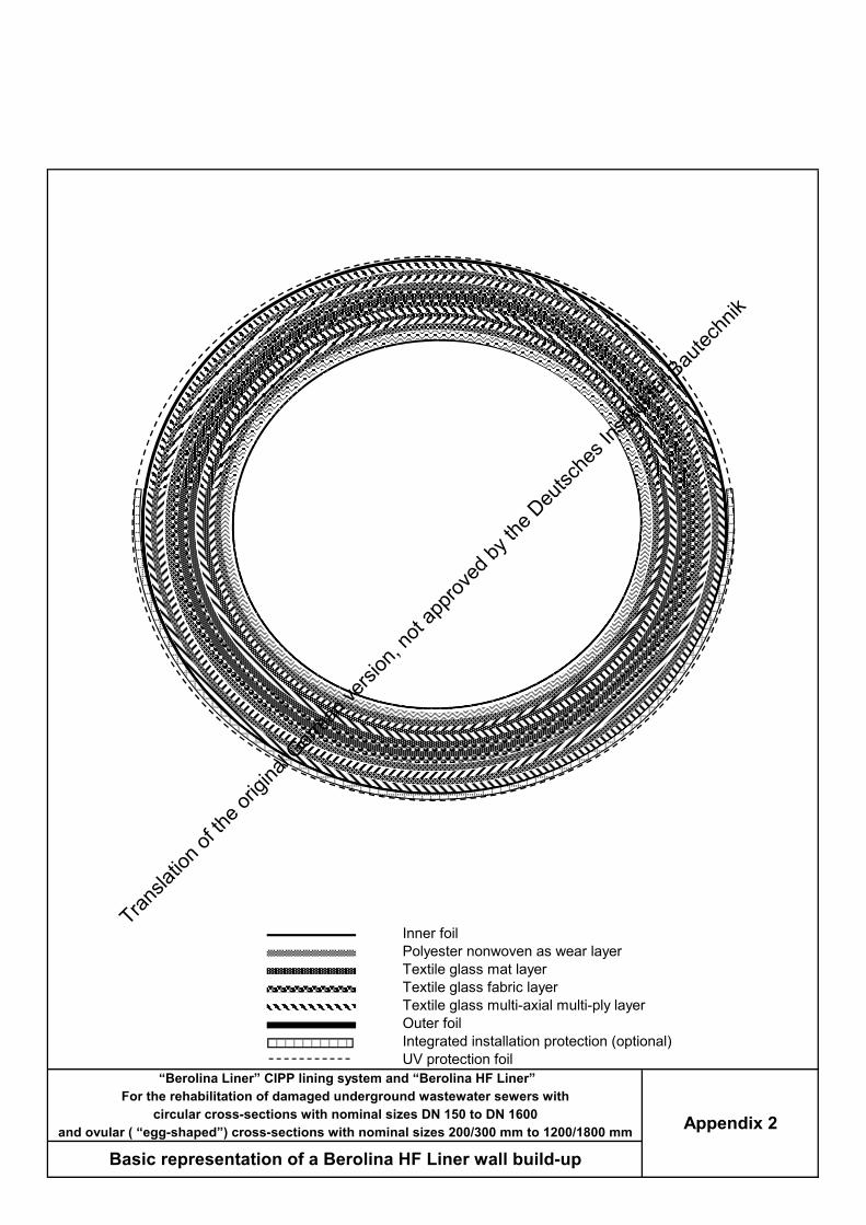
National Technical Approval No. Z-42.3-336 Page 19 of 27 - April 14, 2017 If electrical equipment, e.g. video cameras (CCTV) is introduced into the pipe to be rehabilitated, it must have properties according to the VDE regulations. 4.3 Carrying out the rehabilitation work 4.3.1 Preparatory measures Before starting the work, the sewer to be rehabilitated must be cleaned (see Appendix 6), so that the damage can be readily seen on the monitor. Any obstructions preventing the pulling in of the tube must be removed (e.g. tree roots, protruding lateral connection pipes, tar, etc.). When removing such obstructions, ensure that this is only done with suitable tools, so that it does not cause any additional damage to the host pipe. Before pulling in the liner, ensure that the pipe/sewer concerned is not in use; if necessary, insert cut-off plugs (see Appendix 10) and divert the wastewater (see Appendices 11 and 12). People may only climb into the manholes of the sewers to be rehabilitated if they have been tested beforehand to ensure there are no explosive gases in the length of sewer. The same also applies to the equipment used for the rehabilitation method, which is to be introduced into the length of sewer. To this end, the relevant sections of the following standards are to be observed:
GUV-R 12623 (previously GUV 17.6) DWA-Merkblatt 149-223 DWA-A 199-1 und DWA-A 199-224
The correctness of the information named in section 3 must be checked on site. To this end, the section of the pipe to be rehabilitated must be cleaned with the usual jetting equipment so that the damage can be perfectly identified on the monitor during the visual inspection according to leaflet DWA-M 149-222. The relevant accident prevention regulations must also be observed if people climb into the manholes of the sewers to be rehabilitated and in all steps of the rehabilitation process.
23 GUV-R 126 Sicherheitsregeln: Arbeiten in umschlossenen Räumen von abwassertechnischen Anlagen (bisher GUV 17.6); Ausgabe: 2008-09 24 DWA-A 199-1 Deutsche Vereinigung für Wasserwirtschaft, Abwasser und Abfall e. V. (DWA) - Arbeitsblatt 199: Dienst- und Betriebsanweisung für das Personal von Abwasseranlagen - Teil 1: Dienstanweisung für das Personal von Abwasseranlagen; Ausgabe: 2011-11 DWA-A 199-2 Deutsche Vereinigung für Wasserwirtschaft, Abwasser und Abfall e. V. (DWA)- Arbeitsblatt 199: Dienst- und Betriebsanweisung für das Personal von Abwasseranlagen - Teil 2: Betriebsanweisung für das Personal von Kanalnetzen und Regenwasserbehandlungsanlagen; Ausgabe: 2007-07
Transla
tion o
f the o
rigina
l Germ
an ve
rsion
, not
appro
ved b
y the
Deu
tsche
s Ins
titut fü
r Bau
techn
ik

National Technical Approval No. Z-42.3-336 Page 20 of 27 - April 14, 2017 The steps required for implementation of the method are to be defined for each rehabilitation project using record forms. 4.3.2 Incoming inspection of the system components on the construction site The GRP liners, delivered to site in light and styrene-proof packaging, must be checked on site to ensure the markings named in section 2.2.3 exist, and to ensure the transport packaging according to section 2.2.2 is undamaged. Compliance with the storage and transport temperatures in section 2.2.2 is to be checked. 4.3.3 Checking the UV lamps Brand new UV lamps must be checked for the first time using a calibrated measuring device after approx. 400 hours of operation (see Appendix 22), to see whether or not, at a measuring distance of 200 mm, the radiation intensity is still at least 24 W/mm2 or 2.4 mW/cm2 (comparative measurement). After this, each lamp is to be checked at intervals of 150 operating hours.
4.3.4 Pulling in the smooth foil
Before the GRP liner delivered to the construction site can be pulled into the damaged sewer, e.g. a textile-reinforced polyester strip must always be pulled in as an installation aid (Appendix 13). The width of the smooth foil must be chosen so that the width of the liner to be pulled in is covered with the smooth foil. Instead of the smooth foil, the GRP liner can also be drawn in with integrated PE installation protection foil (Appendix 1 and 2: integrated installation protection (optional)).
4.3.5 Inserting sleeves
Before the GRP liner is pulled in from the start manhole to the end manhole, a sleeve must be inserted, either in a manhole to be passed through or in the end manhole. This must be a sleeve with an outer diameter corresponding to the inner diameter of the pipe to be rehabilitated. This is intended to simulate the supporting effect of the existing host pipe. After pulling in the GRP liner and curing, samples are to be taken in these areas (see section 8).
4.3.6 Pulling in the GRP liner
The GRP liner must be taken from the transport packaging (Appendix 14) in such a way that it is not damaged.
A so-called "pull-in head" is to be made at the end of the liner, i.e. the liner must be folded lengthwise so that a pull in rope can be fixed onto it (e.g. by means of ratchet straps).
The GRP liner must be pulled into the pipe to be rehabilitated via a cable winch, possibly with a pulley at the edge of the start manhole and a deflection bend corresponding to the nominal size of the pipe to be rehabilitated. At the same time, ensure that the liner is not damaged. Biologically degradable oil can be applied to the smooth foil to reduce the pulling
Transla
tion o
f the o
rigina
l Germ
an ve
rsion
, not
appro
ved b
y the
Deu
tsche
s Ins
titut fü
r Bau
techn
ik

National Technical Approval No. Z-42.3-336 Page 21 of 27 - April 14, 2017
in forces.
When pulling in the pipe, if necessary, use so-called "rotating swivel shackles" to ensure that the GRP liner does not twist about its longitudinal axis.
4.3.7 Positioning sealing tapes (auxiliary materials)
After pulling in the liner and before inflating and calibrating the GRP tube, one or two swelling profiled tapes or butyl rubber adhesive tapes must be positioned at approx. 5 cm to 15 cm from the start of the pipe to be rehabilitated. These are to be positioned by hand (see Appendices 20 and 23).
If butyl rubber adhesive tapes are used, then ensure that the adhesive surfaces are dust-free and dry. The tapes must also be positioned in each manhole passed through and at the end manhole in the same way.
4.3.8 Inflating the GRP liner
After the GRP liner has been pulled in, the ends of the tube must be sealed using so-called "packers" (see Appendix 15). Packers designed as air locked can also be used. The GRP liner is to be inflated by applying compressed air. The pressure must be built up as slowly as possible up to max. 0.02 bar.
4.3.9. Inserting the UV light sources After the GRP liner has been inflated, the pressure must be released and the light source related to the nominal size must be fed into the GRP liner (see Appendix 16). If an air lock is used, do not relieve the pressure. In this case the light source must be introduced into the GRP liner via the air lock. The pulling cable of the UV light source and the power supply cable must be pulled through the corresponding openings in the packer. When inserting the UV light source in the GRP liner, ensure that the inner foil is not damaged. 4.3.10 Calibrating the GRP liner
After inflating the liner and inserting the UV light source, after waiting for approx. 3 minutes to 5 minutes, the internal pressure must be increased in pressure stages of 0.05 bar to approx. 0.5 bar. After each pressure stage, a waiting period of approx. 3 to 5 minutes should be allowed for. During the calibration, the approx. 10 % overlapping, resin-impregnated glass fiber complexes move, so that form-fit positioning of the hose liner against the host pipe is achieved. In the case of smaller nominal sizes, higher internal pressures may be necessary for complete expansion.
4.3.11 Curing the GRP liner with light
The light source may only be switched on if there are no longer any people in the start manhole and the UV light source has been completely inserted in the GRP liner.
Transla
tion o
f the o
rigina
l Germ
an ve
rsion
, not
appro
ved b
y the
Deu
tsche
s Ins
titut fü
r Bau
techn
ik

National Technical Approval No. Z-42.3-336 Page 22 of 27 - April 14, 2017
As soon as the light source has been switched on, it must be pulled to the end manhole with a feed speed depending on the nominal size according to the details given in Appendix 17 and 18 or with the contract-related, feed speed previously determined within the scope of the factory production control according to section 2.3.2.
If the UV light sources are switched on, ensure that a minimum spacing of 55 mm is maintained between the individual lamps and the inner surface of the liner, regardless of the nominal size.
During the light curing, heat is produced by the reaction of the resin. The resulting temperatures on the surface of the GRP liner must not exceed a temperature level of approx. +140 °C. The temperature level must be continuously checked using temperature measuring probes while the light source is pulled through and the results recorded. If the temperature exceeds the specified level, the air throughput must be increased by opening a valve in the packer at the end manhole and simultaneously maintaining the internal pressure.
The change in pressure during the light curing, the position of the UV light source, the speed of the UV light source, the functional condition of the UV lamps and the air temperature at the surface of the liner are also to be recorded.
4.3.12 Removing the inner foil (membrane)
After a cooling phase lasting several minutes, the UV light source must be removed from the cured GRP liner, after the pressure has been released. The packers must then be removed and then the inner foil is removed
4.3.13 Leak test on the GRP liner
As an intermediate test, the leak tightness of the cured GRP liner can be checked before cutting open the lateral connections and making the manhole connections (Appendix 19 and 25) according to the criteria in EN 161016 (see also section 6).
4.3.14 Finishing work
After curing and cooling, air-powered cutting tools must be used to cut off and remove the inner pipe that has been made, in the start and end manhole with approx. 2 cm to 3 cm wide overhang at the respective manhole wall. The top half-shell of the pipe made must be removed in the intermediate manholes, down to the bench in the floor of the manhole.
Any samples necessary for the subsequent tests must be taken from the pipe sections removed (see section 6). The cutting work must be carried out in compliance with the relevant accident prevention regulations. 4.3.15 Manhole joint
-
Transla
tion o
f the o
rigina
l Germ
an ve
rsion
, not
appro
ved b
y the
Deu
tsche
s Ins
titut fü
r Bau
techn
ik
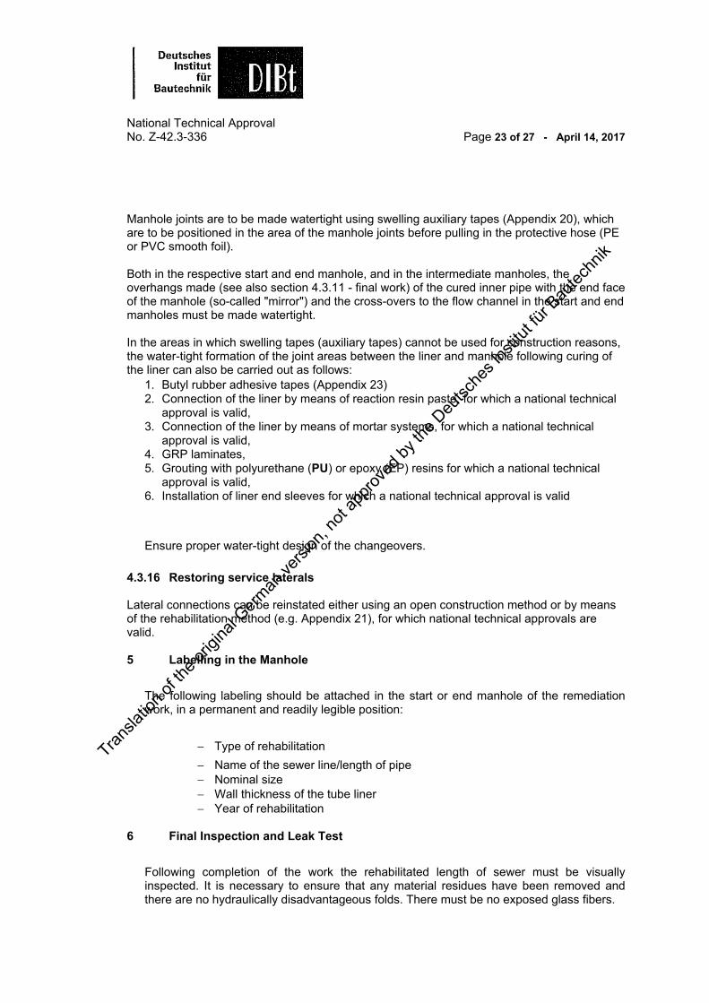
National Technical Approval No. Z-42.3-336 Page 23 of 27 - April 14, 2017 Manhole joints are to be made watertight using swelling auxiliary tapes (Appendix 20), which are to be positioned in the area of the manhole joints before pulling in the protective hose (PE or PVC smooth foil). Both in the respective start and end manhole, and in the intermediate manholes, the overhangs made (see also section 4.3.11 - final work) of the cured inner pipe with the end face of the manhole (so-called "mirror") and the cross-overs to the flow channel in the start and end manholes must be made watertight. In the areas in which swelling tapes (auxiliary tapes) cannot be used for construction reasons, the water-tight formation of the joint areas between the liner and manhole following curing of the liner can also be carried out as follows:
1. Butyl rubber adhesive tapes (Appendix 23) 2. Connection of the liner by means of reaction resin paste, for which a national technical
approval is valid, 3. Connection of the liner by means of mortar systems, for which a national technical
approval is valid, 4. GRP laminates, 5. Grouting with polyurethane (PU) or epoxy (EP) resins for which a national technical
approval is valid, 6. Installation of liner end sleeves for which a national technical approval is valid
Ensure proper water-tight design of the changeovers.
4.3.16 Restoring service laterals Lateral connections can be reinstated either using an open construction method or by means of the rehabilitation method (e.g. Appendix 21), for which national technical approvals are valid. 5 Labelling in the Manhole
The following labeling should be attached in the start or end manhole of the remediation work, in a permanent and readily legible position:
Type of rehabilitation
Name of the sewer line/length of pipe Nominal size Wall thickness of the tube liner Year of rehabilitation
6 Final Inspection and Leak Test
Following completion of the work the rehabilitated length of sewer must be visually inspected. It is necessary to ensure that any material residues have been removed and there are no hydraulically disadvantageous folds. There must be no exposed glass fibers.
Transla
tion o
f the o
rigina
l Germ
an ve
rsion
, not
appro
ved b
y the
Deu
tsche
s Ins
titut fü
r Bau
techn
ik
National Technical Approval No. Z-42.3-336 Page 24 of 27 - April 14, 2017
After curing the liner, including making the manhole connections and renewing the lateral connections, the tightness must be tested. This can also be done section-wise (Appendix 19 and leak test record Appendix 25).
The tightness of the rehabilitated pipes must be tested using water ("W" method) or air ("L" method) to EN 161018 . If testing using air, the specifications in table 3 of EN 161018, LB test methods for dry concrete pipes must be observed.
Lateral connections rehabilitated by means of the top hat technique can also be tested for watertightness separately using suitable inflatable cut-off seals. 7 Tests on Samples Taken 7.1 General information
On the construction site, circular rings or segments are to be taken from the cured circular or approximately circular liners for ovular cross-sections. If the sample pieces taken for the named tests are found to be unsuitable, the tests on the properties to be complied with can be carried out on samples taken directly from the cured liner (sample accompanying document Appendix 26).
For liners with ovular cross-sections, the samples must be taken from the area with the largest buckling load, in the area of the cross-section between 3:00 and 5:00 o'clock.
The sampling point of sewers with ovular cross-sections with width/height dimensions ≥600 mm/900 mm must then be re-sealed using hand applied laminate with the same wall thickness.
The tests of the water tightness of the GRP liner without foil coating, density, glass content, wall construction and strength properties named in section 2.3.2 for the factory production control must also be carried out on the samples to be taken on the respective construction site.
The test on segments must be carried out using the three-point loading test method to EN ISO 17813. Curved test rods from the relevant circular cross-section are to be used, which have been taken from the segments in the radial direction with a minimum width of 50 mm. The span width measured between the support points of the sample rod must be taken into account in the testing and calculation of the modulus of elasticity.
7.2 Water-tightness The water-tightness of the cured GRP liner must be carried out by testing test pieces taken from the cured liner without smooth foil and without foil coating, based on the criteria in EN 161018. The test on test pieces can either be carried out with overpressure or underpressure of 0.5 bar.
If underpressure testing is used, the sample must be impinged on one side with water. At
1
Transla
tion o
f the o
rigina
l Germ
an ve
rsion
, not
appro
ved b
y the
Deu
tsche
s Ins
titut fü
r Bau
techn
ik

National Technical Approval No. Z-42.3-336 Page 25 of 27 - April 14, 2017
an underpressure of 0.5 bar, no water may visibly leak from the side of the sample without water impingement for a test period of 30 minutes.
If testing using overpressure, water pressure of 0.5 bar must be applied for 30 minutes. With this method too, there must be no visible water leaks on the unimpinged side of the sample. 8 Declaration of Compliance for the Rehabilitation Work Carried Out
Compliance of the completed rehabilitation work with this national technical approval must be confirmed by the contractor with a declaration of compliance based on the specifications in Tables 3 and 3. Documents concerning the properties of the system components according to section 2.1.1 and the results of the tests according to table 3 and table 4 must be attached to the declaration of compliance.
The manager of the rehabilitation project or a qualified representative of the manager must be present on the construction site while the rehabilitation work is being carried out. They must ensure proper completion of the work according to the provisions of section 4 and in particular, carry out or organize the tests according to table 3 and arrange the tests according to table 4.
The tests on test pieces according to table 4 are to be carried out by a monitoring body approved by the building control authorities (see list of test, monitoring and certification bodies according to the state building code regulations, (Landesbauordnungen) part V, No. 9).
Once every half-year a liner of a completed rehabilitation project must be sampled by the previously named monitoring body. They must also check the documentation of the rehabilitation projects tests according to table 3.
Table 3: "Process-accompanying tests"
Subject of the test Type of requirement Frequency
Visual inspection of the pipe according to section 4 3.1
d DWA M 149 223
before each rehabilitation
Visual inspection of the pipe according to section 6 and DWA-M 149-223
after each rehabilitation
Equipment requirements according to section 4 2
each construction site
Labeling the containers of the rehabilitation components
according to section 2.2.3
Internal pressures on inflating according to section 4 3 7Temperature level and speed
of the UV light source according to section 4.3.8
Condition of the UV lamps according to section 4 3 3
Air and/or water-tightness according to section 6
Transla
tion o
f the o
rigina
l Germ
an ve
rsion
, not
appro
ved b
y the
Deu
tsche
s Ins
titut fü
r Bau
techn
ik

National Technical Approval No. Z-42.3-336 Page 26 of 27 - April 14, 2017 The tests named in table 4 must be organized by the manager of the rehabilitation work or their qualified representative. Samples for the tests named in table 4 must be taken from the cured GRP liners. The test results must be recorded and evaluated; the must be submitted to the Deutsche Institut für Bautechnik on demand. The number and scope of the listed specifications are minimum requirements. Table 4: "Tests on samples"
Subject of the test Type of requirement Frequency
Short-term modulus of elasticity in flexure, short-term flexural stress σfB and creep tendency at pipe cut-outs or circular rings
according to sections 2.3.2 and 7
each construction site, at least every second tube liner
Density and glass content of the sample without smooth foil and without coating foil
According to sections 2.3.2 and 2.1.2.3
Water-tightness of the sample without smooth foil and without coating foil according to section 7.2
Wall construction According to sections 2.3.2 and 2.1.2.1
Ring stiffness and creep tendency at pipe sections or cut-outs according to section 2.3.2
With each change of the resin supplier with declaration of the resins
Resin identity by means of IR spectroscopy
according to section 2.1.1. With each change of the resin supplier with declaration of the resins
Creep tendency at pipe sections or cut-outs
according to section 7.2
If the values are less than the short-term modulus of elasticity named in section 9 and at least 1 x liner per half-year
9 Provisions for the Dimensioning Structural calculations are to be performed to verify the stability of the planned liner for each rehabilitation project according to Leaflet DWA-A 143-28 of the "Deutsche Vereinigung für Wasserwirtschaft, Abwasser und Abfall e. V. (DWA)" before the work begins. In the structural calculations a partial factor of safety of γM = 1.35 was determined for the liner
Transla
tion o
f the o
rigina
l Germ
an ve
rsion
, not
appro
ved b
y the
Deu
tsche
s Ins
titut fü
r Bau
techn
ik

National Technical Approval No. Z-42.3-336 Page 27 of 27 - April 14, 2017 material. The reduction factor A for determining the long-term values has been determined based on EN 76125. The following values are to be taken into account in the structural calculations:
"Berolina Liner" Circumferential modulus of elasticity, short-term, based on EN 122812: 10,000 N/mm2 Circumferential modulus of elasticity, long-term: 6,800 N/mm2 Short-term flexural stress σfB based on EN ISO 11296-42 (EN ISO 17813): 150 N/mm2 Long-term flexural stress σfB: 105 N/mm2 Reduction factor A after 10,000 h: 1.45
"Berolina HF Liner" Circumferential modulus of elasticity, short-term, based on EN 122812: 17,000 N/mm2 Circumferential modulus of elasticity, long-term: 14,200 N/mm2 Short-term flexural stress σfB based on EN ISO 11296-42 (EN ISO 17813): 280 N/mm2 Long-term flexural stress σfB: 235 N/mm2 Reduction factor A after 10,000 h: 1.19 Rudolf Kersten Head of Department
[Stamp: Deutsches Insitut für Bautechnik] Authenticated [Signature]
25 EN 761 Plastics piping systems. Glass-reinforced thermosetting plastics (GRP) pipes. Determination of the creep factor under dry conditions; German version EN 761:1994; Published: 1994-08
Transla
tion o
f the o
rigina
l Germ
an ve
rsion
, not
appro
ved b
y the
Deu
tsche
s Ins
titut fü
r Bau
techn
ik

Inner foilPolyester nonwoven as wear layerTextile glass mat layerTextile glass fabric layerOuter foilIntegrated installation protection (optional)UV protection foil
“Berolina Liner" CIPP lining system and “Berolina HF Liner”
Appendix 1
For the rehabilitation of damaged underground wastewater sewers withcircular cross-sections with nominal sizes DN 150 to DN 1600
and ovular (“egg-shaped”) cross-sections with nominal sizes 200/300 mm to 1200/1800 mm
Basic representation of a Berolina Liner wall build-up
Transla
tion o
f the o
rigina
l Germ
an ve
rsion
, not
appro
ved b
y the
Deu
tsche
s Ins
titut fü
r Bau
techn
ik
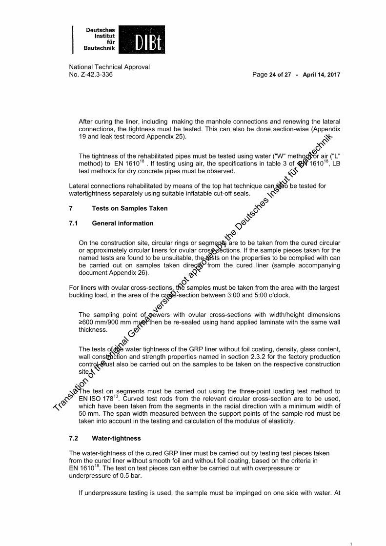
Inner foilPolyester nonwoven as wear layerTextile glass mat layerTextile glass fabric layerTextile glass multi-axial multi-ply layerOuter foilIntegrated installation protection (optional)UV protection foil
“Berolina Liner” CIPP lining system and “Berolina HF Liner”
Appendix 2
For the rehabilitation of damaged underground wastewater sewers withcircular cross-sections with nominal sizes DN 150 to DN 1600
and ovular ( “egg-shaped”) cross-sections with nominal sizes 200/300 mm to 1200/1800 mm
Basic representation of a Berolina HF Liner wall build-up
Transla
tion o
f the o
rigina
l Germ
an ve
rsion
, not
appro
ved b
y the
Deu
tsche
s Ins
titut fü
r Bau
techn
ik

Short-term modulus of elasticity 10,000 N/mm²
Liner thickness 3,5 4,0 4,5 5,0 6,0 7,0 8,0DN 150 41.734 N/m² 70.194 N/m² 109.629 N/m² 162.014 N/m²
DN 200 17.295 N/m² 29.013 N/m² 45.193 N/m² 66.612 N/m² 128.385 N/m² 221.010 N/m²
DN 225 12.075 N/m² 20.239 N/m² 31.498 N/m² 46.386 N/m² 89.246 N/m² 153.361 N/m²
DN 250 8.761 N/m² 14.674 N/m² 22.822 N/m² 33.586 N/m² 64.528 N/m² 110.730 N/m² 175.574 N/m²
DN 300 5.034 N/m² 8.423 N/m² 13.087 N/m² 19.239 N/m² 36.887 N/m² 63.166 N/m² 99.944 N/m²
DN 315 4.341 N/m² 7.262 N/m² 11.281 N/m² 16.580 N/m² 31.772 N/m² 54.379 N/m² 85.999 N/m²
DN 350 3,193 N/mm² 5.274 N/m² 8.188 N/m² 12.028 N/m² 23.027 N/m² 39.373 N/m² 62.205 N/m²
DN 375 2,588 N/mm² 4.278 N/m² 6.640 N/m² 9.751 N/m² 18.657 N/m² 31.882 N/m² 50.339 N/m²
DN 400 2,128 N/mm² 3.518 N/m² 5.459 N/m² 8.014 N/m² 15.326 N/m² 26.176 N/m² 41.309 N/m²
DN 450 2.462 N/m² 3.819 N/m² 5.605 N/m² 10.710 N/m² 18.276 N/m² 28.816 N/m²
DN 480 2.026 N/m² 3.141 N/m² 4.609 N/m² 8.802 N/m² 15.014 N/m² 23.664 N/m²
DN 500 1.790 N/m² 2.776 N/m² 4.072 N/m² 7.776 N/m² 13.260 N/m² 20.893 N/m²
DN 550 2.080 N/m² 3.051 N/m² 5.823 N/m² 9.924 N/m² 15.628 N/m²
DN 580 1.772 N/m² 2.598 N/m² 4.957 N/m² 8.445 N/m² 13.296 N/m²
DN 600 1.599 N/m² 2.345 N/m² 4.473 N/m² 7.619 N/m² 11.993 N/m²
DN 650 1.256 N/m² 1.841 N/m² 3.510 N/m² 5.977 N/m² 9.404 N/m²
DN 675 1.120 N/m² 1.642 N/m² 3.131 N/m² 5.330 N/m² 8.385 N/m²
DN 700 1.004 N/m² 1.471 N/m² 2.804 N/m² 4.774 N/m² 7.509 N/m²
DN 750 815 N/m² 1.195 N/m² 2.276 N/m² 3.874 N/m² 6.091 N/m²
DN 800 671 N/m² 983 N/m² 1.873 N/m² 3.186 N/m² 5.009 N/m²
DN 850 1.559 N/m² 2.652 N/m² 4.168 N/m²
DN 883 2.364 N/m² 3.714 N/m²
DN 900 2.231 N/m² 3.506 N/m²
DN 1000 1630 N/mm² 2.549 N/m²
DN 1050 1.406 N/m² 2.199 N/m²
DN 1100 1.221 N/m² 1.911 N/m²
DN 1136 1.108 N/m² 1.734 N/m²
DN 1170 1.014 N/m² 1.586 N/m²
DN 1200 939 N/m² 1.469 N/m²
DN 1250 1.303 N/m²
DN 1300 1.158 N/m²
DN 1400DN 1500DN 1600
Ovular cross-sections200/300 2.896 N/m² 4.842 N/m² 7.516 N/m² 11.040 N/m² 21.130 N/m² 36.121 N/m² 57.053 N/m²
250/375 1.474 N/m² 2.462 N/m² 3.819 N/m² 5.605 N/m² 10.710 N/m² 18.276 N/m² 28.816 N/m²
300/450 850 N/m² 1.419 N/m² 2.199 N/m² 3.225 N/m² 6.156 N/m² 10.493 N/m² 16.526 N/m²
350/525 891 N/m² 1.380 N/m² 2.023 N/m² 3.858 N/m² 6.571 N/m² 10.340 N/m²
400/600 595 N/m² 922 N/m² 1.351 N/m² 2.575 N/m² 4.383 N/m² 6.894 N/m²
500/750 470 N/m² 689 N/m² 1.312 N/m² 2.231 N/m² 3.506 N/m²
600/900 271 N/m² 398 N/m² 757 N/m² 1.286 N/m² 2.020 N/m²
700/1050 808 N/m² 1.268 N/m²
800/1200 542 N/m² 850 N/m²
900/1350 380 N/m² 596 N/m²
1000/1500 433 N/m²
1200/1800
Non-load-bearing layers : Wear layer 0.5 mm and external foil 0.3 mm = 0.8 mm (are not taken into account in the structural calculations)
“Berolina Liner” CIPP lining system and “Berolina HF Liner”
Appendix 3
For the rehabilitation of damaged underground wastewater sewers with
circular cross-sections with nominal sizes DN 150 to DN 1600
and ovular (“egg-shaped”) cross-sections with nominal sizes 200/300 mm to 1200/1800 mm
Berolina Liner Table of short-term ring stiffness (SR) Part 1
Transla
tion o
f the o
rigina
l Germ
an ve
rsion
, not
appro
ved b
y the
Deu
tsche
s Ins
titut fü
r Bau
techn
ik

Short-term modulus of elasticity 10,000 N/mm²
Liner thickness 9,0 10,0 11,0 12,0 13,0 14,0 15,0 16,0 DN 150DN 200DN 225DN 250DN 300 149.167 N/m²
DN 315 128.288 N/m²
DN 350 92.702 N/m²
DN 375 74.973 N/m²
DN 400 61.492 N/m² 87.514 N/m²
DN 450 42.858 N/m² 60.942 N/m² 83.621 N/m²
DN 480 35.179 N/m² 50.001 N/m² 68.579 N/m²
DN 500 31.053 N/m² 44.125 N/m² 60.504 N/m²
DN 550 23.214 N/m² 32.968 N/m² 45.180 N/m²
DN 580 19.744 N/m² 28.032 N/m² 38.404 N/m² 51.111 N/m²
DN 600 17.807 N/m² 25.276 N/m² 34.623 N/m² 46.071 N/m²
DN 650 13.956 N/m² 19.803 N/m² 27.115 N/m² 36.066 N/m²
DN 675 12.443 N/m² 17.653 N/m² 24.166 N/m² 32.138 N/m²
DN 700 11.141 N/m² 15.802 N/m² 21.630 N/m² 28.761 N/m²
DN 750 9.034 N/m² 12.811 N/m² 17.530 N/m² 23.302 N/m²
DN 800 7.427 N/m² 10.529 N/m² 14.404 N/m² 19.142 N/m²
DN 850 6.180 N/m² 8.759 N/m² 11.979 N/m² 15.916 N/m² 20.645 N/m² 26.243 N/m²
DN 883 5.506 N/m² 7.802 N/m² 10.670 N/m² 14.175 N/m² 18.384 N/m² 23.365 N/m² 29.189 N/m² 35.924 N/m²
DN 900 5.197 N/m² 7.364 N/m² 10.069 N/m² 13.376 N/m² 17.347 N/m² 22.046 N/m² 27.539 N/m² 33.891 N/m²
DN 1000 3.777 N/m² 5.350 N/m² 7.313 N/m² 9.712 N/m² 12.590 N/m² 15.996 N/m² 19.974 N/m² 24.573 N/m²
DN 1050 3.258 N/m² 4.615 N/m² 6.308 N/m² 8.375 N/m² 10.856 N/m² 13.790 N/m² 17.217 N/m² 21.178 N/m²
DN 1100 2.831 N/m² 4.009 N/m² 5.478 N/m² 7.272 N/m² 9.425 N/m² 11.971 N/m² 14.945 N/m² 18.380 N/m²
DN 1136 2.568 N/m² 3.636 N/m² 4.969 N/m² 6.596 N/m² 8.548 N/m² 10.856 N/m² 13.551 N/m² 16.664 N/m²
DN 1170 2.349 N/m² 3.326 N/m² 4.544 N/m² 6.032 N/m² 7.816 N/m² 9.926 N/m² 12.389 N/m² 15.234 N/m²
DN 1200 2.176 N/m² 3.081 N/m² 4.209 N/m² 5.586 N/m² 7.238 N/m² 9.191 N/m² 11.471 N/m² 14.105 N/m²
DN 1250 1.923 N/m² 2.723 N/m² 3.720 N/m² 4.936 N/m² 6.396 N/m² 8.120 N/m² 10.134 N/m² 12.459 N/m²
DN 1300 1.714 N/m² 2.418 N/m² 3.303 N/m² 4.383 N/m² 5.679 N/m² 7.210 N/m² 8.996 N/m² 11.060 N/m²
DN 1400 1.933 N/m² 2.640 N/m² 3.503 N/m² 4.537 N/m² 5.759 N/m² 7.185 N/m² 8.831 N/m²
DN 1500 1.569 N/m² 2.143 N/m² 2.843 N/m² 3.682 N/m² 4.673 N/m² 5.829 N/m² 7.164 N/m²
DN 1600 1.291 N/m² 1.763 N/m² 2.339 N/m² 3.029 N/m² 3.843 N/m² 4.794 N/m² 5.891 N/m²Ovular cross-sections
200/300250/375 42.858 N/m²
300/450 24.551 N/m²
350/525 15.349 N/m² 21.782 N/m² 29.829 N/m²
400/600 10.227 N/m² 14.504 N/m² 19.850 N/m²
500/750 5.197 N/m² 7.364 N/m² 10.069 N/m² 13.376 N/m² 17.347 N/m² 22.046 N/m² 27.539 N/m² 33.891 N/m²
600/900 2.992 N/m² 4.238 N/m² 5.791 N/m² 7.689 N/m² 9.965 N/m² 12.658 N/m² 15.802 N/m² 19.436 N/m²
700/1050 1.877 N/m² 2.658 N/m² 3.631 N/m² 4.819 N/m² 6.243 N/m² 7.926 N/m² 9.892 N/m² 12.161 N/m²
800/1200 1.254 N/m² 1.775 N/m² 2.424 N/m² 3.216 N/m² 4.166 N/m² 5.288 N/m² 6.597 N/m² 8.108 N/m²
900/1350 879 N/m² 1.244 N/m² 1.698 N/m² 2.253 N/m² 2.917 N/m² 3.702 N/m² 4.617 N/m² 5.673 N/m²1000/1500 640 N/m² 905 N/m² 1.236 N/m² 1.639 N/m² 2.121 N/m² 2.691 N/m² 3.356 N/m² 4.123 N/m²1200/1800 522 N/m² 713 N/m² 945 N/m² 1.223 N/m² 1.551 N/m² 1.934 N/m² 2.376 N/m²
Non-load-bearing layers : Wear layer 0.5 mm and external foil 0.3 mm = 0.8 mm (are not taken into account in the structural calculations)
“Berolina Liner” CIPP lining system and “Berolina HF Liner”
Appendix 4
For the rehabilitation of damaged underground wastewater sewers withcircular cross-sections with nominal sizes DN 150 to DN 1600
and ovular (“egg-shaped”) cross-sections with nominal sizes 200/300 mm to 1200/1800 mm
Berolina Liner Table of short-term ring stiffness (SR) Part 2
Transla
tion o
f the o
rigina
l Germ
an ve
rsion
, not
appro
ved b
y the
Deu
tsche
s Ins
titut fü
r Bau
techn
ik

Short-term modulus of elasticity 17,000 N/mm²
Liner thickness 3,5 4,0 4,5 5,0 6,0 7,0 8,0DN 150 70.513 N/m² 118.597 N/m² 185.221 N/m² 273.721 N/m²
DN 200 29.267 N/m² 49.096 N/m² 76.476 N/m² 112.719 N/m² 217.245 N/m² 373.970 N/m²
DN 225 20.444 N/m² 34.266 N/m² 53.329 N/m² 78.535 N/m² 151.096 N/m² 259.640 N/m²
DN 250 14.839 N/m² 24.855 N/m² 38.656 N/m² 56.887 N/m² 109.294 N/m² 187.545 N/m² 297.368 N/m²
DN 300 8.532 N/m² 14.276 N/m² 22.180 N/m² 32.607 N/m² 62.517 N/m² 107.052 N/m² 169.383 N/m²
DN 315 7.359 N/m² 12.310 N/m² 19.121 N/m² 28.103 N/m² 53.855 N/m² 92.175 N/m² 145.770 N/m²
DN 350 5.348 N/m² 8.942 N/m² 13.883 N/m² 20.395 N/m² 39.044 N/m² 66.759 N/m² 105.471 N/m²
DN 375 4.340 N/m² 7.255 N/m² 11.260 N/m² 16.537 N/m² 31.640 N/m² 54.066 N/m² 85.367 N/m²
DN 400 3.571 N/m² 5.967 N/m² 9.258 N/m² 13.593 N/m² 25.995 N/m² 44.398 N/m² 70.065 N/m²
DN 450 4.178 N/m² 6.480 N/m² 9.509 N/m² 18.169 N/m² 31.006 N/m² 48.888 N/m²
DN 480 3.437 N/m² 5.330 N/m² 7.820 N/m² 14.935 N/m² 25.476 N/m² 40.151 N/m²
DN 500 3.038 N/m² 4.710 N/m² 6.910 N/m² 13.195 N/m² 22.501 N/m² 35.454 N/m²
DN 550 3.531 N/m² 5.178 N/m² 9.882 N/m² 16.843 N/m² 26.524 N/m²
DN 580 3.007 N/m² 4.410 N/m² 8.413 N/m² 14.335 N/m² 22.568 N/m²
DN 600 2.714 N/m² 3.980 N/m² 7.592 N/m² 12.933 N/m² 20.358 N/m²
DN 650 2.131 N/m² 3.125 N/m² 5.958 N/m² 10.146 N/m² 15.964 N/m²
DN 675 1.902 N/m² 2.788 N/m² 5.315 N/m² 9.049 N/m² 14.236 N/m²
DN 700 1.704 N/m² 2.498 N/m² 4.761 N/m² 8.105 N/m² 12.749 N/m²
DN 750 1.384 N/m² 2.028 N/m² 3.865 N/m² 6.577 N/m² 10.342 N/m²
DN 800 1.139 N/m² 1.669 N/m² 3.180 N/m² 5.410 N/m² 8.505 N/m²
DN 850 2.648 N/m² 4.504 N/m² 7.079 N/m²
DN 883 4.014 N/m² 6.308 N/m²
DN 900 3.789 N/m² 5.954 N/m²
DN 1000 2.756 N/m² 4.329 N/m²
DN 1050 2.379 N/m² 3.736 N/m²
DN 1100 2.067 N/m² 3.246 N/m²
DN 1136 1.875 N/m² 2.945 N/m²
DN 1170 1.716 N/m² 2.694 N/m²
DN 1200 1.590 N/m² 2.496 N/m²
DN 1250 2.206 N/m²
DN 1300 1.960 N/m²
DN 1400DN 1500DN 1600
Ovular cross-sections200/300 4.911 N/m² 8.210 N/m² 12.745 N/m² 18.721 N/m² 35.831 N/m² 61.249 N/m² 96.742 N/m²
250/375 2.501 N/m² 4.178 N/m² 6.480 N/m² 9.509 N/m² 18.169 N/m² 31.006 N/m² 48.888 N/m²
300/450 1.442 N/m² 2.408 N/m² 3.732 N/m² 5.474 N/m² 10.447 N/m² 17.808 N/m² 28.047 N/m²
350/525 1.512 N/m² 2.342 N/m² 3.434 N/m² 6.549 N/m² 11.154 N/m² 17.553 N/m²
400/600 1.010 N/m² 1.565 N/m² 2.294 N/m² 4.372 N/m² 7.442 N/m² 11.705 N/m²
500/750 799 N/m² 1.170 N/m² 2.228 N/m² 3.789 N/m² 5.954 N/m²
600/900 461 N/m² 675 N/m² 1.285 N/m² 2.185 N/m² 3.431 N/m²
700/1050 1.372 N/m² 2.154 N/m²
800/1200 917 N/m² 1.440 N/m²
900/1350 643 N/m² 1.009 N/m²
1000/1500 735 N/m²
1200/1800
Non-load-bearing layers : Wear layer 0.5 mm and external foil 0.3 mm = 0.8 mm (not taken into account in the structural calculations)
“Berolina Liner” CIPP lining system and “Berolina HF Liner”
Appendix 5
For the rehabilitation of damaged underground wastewater sewers with
circular cross-sections with nominal sizes DN 150 to DN 1600
and ovular (“egg-shaped”) cross-sections with nominal sizes 200/300 mm to 1200/1800 mm
Berolina HF Liner Table of short-term ring stiffness (SR) Part 1
Transla
tion o
f the o
rigina
l Germ
an ve
rsion
, not
appro
ved b
y the
Deu
tsche
s Ins
titut fü
r Bau
techn
ik

Short-term modulus of elasticity 17,000 N/mm²
Liner thickness 9,0 10,0 11,0 12,0 13,0 14,0 15,0 16,0 DN 150DN 200DN 225DN 250DN 300 252.800 N/m²
DN 315 217.449 N/m²
DN 350 157.177 N/m²
DN 375 127.142 N/m²
DN 400 104.296 N/m² 148.431 N/m²
DN 450 72.711 N/m² 103.389 N/m² 141.865 N/m²
DN 480 59.691 N/m² 84.839 N/m² 116.361 N/m²
DN 500 52.694 N/m² 74.875 N/m² 102.667 N/m²
DN 550 39.399 N/m² 55.952 N/m² 76.677 N/m²
DN 580 33.512 N/m² 47.579 N/m² 65.183 N/m² 86.752 N/m²
DN 600 30.226 N/m² 42.904 N/m² 58.769 N/m² 78.202 N/m² 101.591 N/m²
DN 650 23.693 N/m² 33.618 N/m² 46.030 N/m² 61.226 N/m² 79.507 N/m²
DN 675 21.125 N/m² 29.969 N/m² 41.027 N/m² 54.561 N/m² 70.839 N/m²
DN 700 18.915 N/m² 26.829 N/m² 36.723 N/m² 48.829 N/m² 63.387 N/m² 80.638 N/m²
DN 750 15.340 N/m² 21.752 N/m² 29.764 N/m² 39.565 N/m² 51.346 N/m² 65.300 N/m²
DN 800 12.612 N/m² 17.879 N/m² 24.459 N/m² 32.504 N/m² 42.171 N/m² 53.618 N/m²
DN 850 10.494 N/m² 14.874 N/m² 20.343 N/m² 27.028 N/m² 35.059 N/m² 44.565 N/m²
DN 883 9.350 N/m² 13.250 N/m² 18.120 N/m² 24.072 N/m² 31.220 N/m² 39.680 N/m² 49.569 N/m² 61.007 N/m²
DN 900 8.825 N/m² 12.506 N/m² 17.101 N/m² 22.716 N/m² 29.460 N/m² 37.440 N/m² 46.768 N/m² 57.556 N/m²
DN 1000 6.415 N/m² 9.087 N/m² 12.422 N/m² 16.495 N/m² 21.384 N/m² 27.168 N/m² 33.925 N/m² 41.736 N/m²
DN 1050 5.534 N/m² 7.839 N/m² 10.714 N/m² 14.225 N/m² 18.438 N/m² 23.422 N/m² 29.243 N/m² 35.971 N/m²
DN 1100 4.808 N/m² 6.809 N/m² 9.305 N/m² 12.353 N/m² 16.010 N/m² 20.334 N/m² 25.385 N/m² 31.221 N/m²
DN 1136 4.362 N/m² 6.177 N/m² 8.440 N/m² 11.204 N/m² 14.519 N/m² 18.440 N/m² 23.017 N/m² 28.306 N/m²
DN 1170 3.990 N/m² 5.650 N/m² 7.719 N/m² 10.246 N/m² 13.277 N/m² 16.860 N/m² 21.044 N/m² 25.878 N/m²
DN 1200 3.696 N/m² 5.233 N/m² 7.150 N/m² 9.489 N/m² 12.296 N/m² 15.613 N/m² 19.487 N/m² 23.961 N/m²
DN 1250 3.267 N/m² 4.625 N/m² 6.319 N/m² 8.386 N/m² 10.865 N/m² 13.795 N/m² 17.215 N/m² 21.165 N/m²
DN 1300 2.902 N/m² 4.108 N/m² 5.612 N/m² 7.447 N/m² 9.647 N/m² 12.248 N/m² 15.283 N/m² 18.788 N/m²
DN 1400 3.284 N/m² 4.485 N/m² 5.951 N/m² 7.708 N/m² 9.784 N/m² 12.207 N/m² 15.004 N/m²
DN 1500 2.666 N/m² 3.641 N/m² 4.830 N/m² 6.255 N/m² 7.939 N/m² 9.903 N/m² 12.171 N/m²
DN 1600 2.194 N/m² 2.996 N/m² 3.974 N/m² 5.146 N/m² 6.530 N/m² 8.145 N/m² 10.009 N/m²
Ovular cross-sections200/300250/375 72.711 N/m²
300/450 41.666 N/m²
350/525 31.118 N/m² 36.976 N/m² 50.635 N/m²
400/600 20.738 N/m² 24.626 N/m² 33.703 N/m²
500/750 10.540 N/m² 12.506 N/m² 17.101 N/m² 22.716 N/m² 29.460 N/m²
600/900 6.070 N/m² 7.198 N/m² 9.837 N/m² 13.060 N/m² 16.927 N/m² 21.500 N/m²
700/1050 3.809 N/m² 4.515 N/m² 6.168 N/m² 8.186 N/m² 10.605 N/m² 13.465 N/m² 16.804 N/m² 20.659 N/m²
800/1200 2.545 N/m² 3.016 N/m² 4.119 N/m² 5.465 N/m² 7.078 N/m² 8.984 N/m² 11.207 N/m² 13.775 N/m²
900/1350 1.784 N/m² 2.113 N/m² 2.886 N/m² 3.827 N/m² 4.956 N/m² 6.289 N/m² 7.844 N/m² 9.639 N/m²
1000/1500 1.298 N/m² 1.538 N/m² 2.099 N/m² 2.784 N/m² 3.604 N/m² 4.573 N/m² 5.703 N/m² 7.006 N/m²
1200/1800 888 N/m² 1.211 N/m² 1.606 N/m² 2.079 N/m² 2.636 N/m² 3.287 N/m² 4.037 N/m²
“Berolina Liner” CIPP lining system and “Berolina HF Liner”
Appendix 6
For the rehabilitation of damaged underground wastewater sewers withcircular cross-sections with nominal sizes DN 150 to DN 1600
and ovular (“egg-shaped”) cross-sections with nominal sizes 200/300 mm to 1200/1800 mm
Berolina HF Liner Table of short-term ring stiffness (SR) Part 2
Non-load-bearing layers : Wear layer 0.5 mm and external foil 0.3 mm = 0.8 mm (not taken into account in the structural calculations)
Transla
tion o
f the o
rigina
l Germ
an ve
rsion
, not
appro
ved b
y the
Deu
tsche
s Ins
titut fü
r Bau
techn
ik

Coupling for plug-in connection Quick-release connectorwith bayonet lock
4 curved connection armsprevent local overshadowing
Liner UVA lamp
Directional spring
the arrangement of the nominal size -specific, spring-mounted spacerroller is offset by 45 ° each
flexible, steel-armoredconnection cable to theother lamp pulling units
UV lamp pulling unit for DN 150 to DN 300
“Berolina Liner” CIPP lining system and “Berolina HF Liner”
Appendix 7
For the rehabilitation of damaged underground wastewater sewers withcircular cross-sections with nominal sizes DN 150 to DN 1600
and ovular (“egg-shaped”) cross-sections with nominal sizes 200/300 mm to 1200/1800 mm
Schematic diagram of an element of a UV light train
2
Transla
tion o
f the o
rigina
l Germ
an ve
rsion
, not
appro
ved b
y the
Deu
tsche
s Ins
titut fü
r Bau
techn
ik

Coupling for plug-in connectionwith bayonet lock Quick-release connector
UVA lamp UVA lampflexible, steel-armored
Reflectors Reflectors connection cable to theother lamp pulling units
nominal size-specific,spring-mounted spacer rollers
3 UVA lamps are mounted on each lamp pulling unit;up to 4 units can be plugged together to form a light train
UV lamp pulling unit for DN 400 to DN 600
“Berolina Liner” CIPP lining system and “Berolina HF Liner”
Appendix 8
For the rehabilitation of damaged underground wastewater sewers withcircular cross-sections with nominal sizes DN 150 to DN 1600
and ovular (“egg-shaped”) cross-sections with nominal sizes 200/300 mm to 1200/1800 mm
Schematic diagram of an element of a UV light train
Transla
tion o
f the o
rigina
l Germ
an ve
rsion
, not
appro
ved b
y the
Deu
tsche
s Ins
titut fü
r Bau
techn
ik

Coupling for plug-in connectionwith bayonet lock
Directional springs Quick-release connector
Liner UVA lamp flexible, steel-armoredconnection cable to the
UVA lamp Reflectors other lamp pulling units
nominal size-specific,spring-mounted spacer rollers
4 UVA lamps are mounted on each lamp pulling unit;up to 3 units can be plugged together to form a light train
UV lamp pulling unit for DN 600 and larger
“Berolina Liner” CIPP lining system and “Berolina HF Liner”
Appendix 9
For the rehabilitation of damaged underground wastewater sewers withcircular cross-sections with nominal sizes DN 150 to DN 1600
and ovular (“egg-shaped”) cross-sections with nominal sizes 200/300 mm to 1200/1800 mm
Schematic diagram of an element of a UV light train
Transla
tion o
f the o
rigina
l Germ
an ve
rsion
, not
appro
ved b
y the
Deu
tsche
s Ins
titut fü
r Bau
techn
ik
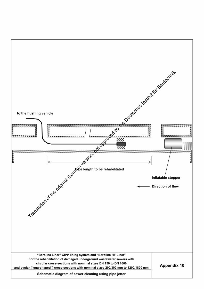
to the flushing vehicle
Inflatable stopper
Direction of flow
Pipe length to be rehabilitated
“Berolina Liner” CIPP lining system and “Berolina HF Liner”
Appendix 10
For the rehabilitation of damaged underground wastewater sewers withcircular cross-sections with nominal sizes DN 150 to DN 1600
and ovular (“egg-shaped”) cross-sections with nominal sizes 200/300 mm to 1200/1800 mm
Schematic diagram of sewer cleaning using pipe jetter
Transla
tion o
f the o
rigina
l Germ
an ve
rsion
, not
appro
ved b
y the
Deu
tsche
s Ins
titut fü
r Bau
techn
ik

Inflatable stopperInflatable stopper
Direction of flow
Pump
Pipe length to be rehabilitated
“Berolina Liner” CIPP lining system and “Berolina HF Liner”
Appendix 11
For the rehabilitation of damaged underground wastewater sewers withcircular cross-sections with nominal sizes DN 150 to DN 1600
and ovular (“egg-shaped”) cross-sections with nominal sizes 200/300 mm to 1200/1800 mm
Schematic diagram of a pipe length with a bypass
Transla
tion o
f the o
rigina
l Germ
an ve
rsion
, not
appro
ved b
y the
Deu
tsche
s Ins
titut fü
r Bau
techn
ik

to the video camera / recording
Inflatable stopper
Direction of flow
Pipe length to be rehabilitated
“Berolina Liner” CIPP lining system and “Berolina HF Liner”
Appendix 12
For the rehabilitation of damaged underground wastewater sewers withcircular cross-sections with nominal sizes DN 150 to DN 1600
and ovular (“egg-shaped”) cross-sections with nominal sizes 200/300 mm to 1200/1800 mm
Schematic diagram of CCTV inspection and single pipe length
Transla
tion o
f the o
rigina
l Germ
an ve
rsion
, not
appro
ved b
y the
Deu
tsche
s Ins
titut fü
r Bau
techn
ik

to the cable winchSteel cable
Slack
Inflatable stopper Inflatable stopper
Thoroughly install pulleys
Pipe length to be rehabilitated
“Berolina Liner” CIPP lining system and “Berolina HF Liner”
Appendix 13
For the rehabilitation of damaged underground wastewater sewers withcircular cross-sections with nominal sizes DN 150 to DN 1600
and ovular (“egg-shaped”) cross-sections with nominal sizes 200/300 mm to 1200/1800 mm
Schematic diagram of pulling in the smooth foil
Transla
tion o
f the o
rigina
l Germ
an ve
rsion
, not
appro
ved b
y the
Deu
tsche
s Ins
titut fü
r Bau
techn
ik

when pulling the liner into thesewer, protect it against lateraldamage
to the cable winchSteel cable
Packer
Inflatable stopper Inflatable stopper
Smooth foil Thoroughly install pulleys
Pipe length to be rehabilitated
“Berolina Liner” CIPP lining system and “Berolina HF Liner”
Appendix 14
For the rehabilitation of damaged underground wastewater sewers withcircular cross-sections with nominal sizes DN 150 to DN 1600
and ovular (“egg-shaped”) cross-sections with nominal sizes 200/300 mm to 1200/1800 mm
Schematic diagram of pulling in the liner
Transla
tion o
f the o
rigina
l Germ
an ve
rsion
, not
appro
ved b
y the
Deu
tsche
s Ins
titut fü
r Bau
techn
ik

Sealing tape, radially all-roundat both manhole ends
Pulling forward the light train by the cable > speed > temperature > operation of UV lamps
Internal pressure monitoring
Inflatable stopper Inflatable stopperLight train Berolina Liner
Packer with ratchet straps Packer with ratchet straps
Pipe length to be rehabilitated
“Berolina Liner” CIPP lining system and “Berolina HF Liner”
Appendix 15
For the rehabilitation of damaged underground wastewater sewers withcircular cross-sections with nominal sizes DN 150 to DN 1600
and ovular (“egg-shaped”) cross-sections with nominal sizes 200/300 mm to 1200/1800 mm
Schematic diagram of the liner curing by means of the light train
Transla
tion o
f the o
rigina
l Germ
an ve
rsion
, not
appro
ved b
y the
Deu
tsche
s Ins
titut fü
r Bau
techn
ik

the air lockscan be verticalor horizontal-
Liner
Air lock Light train Webbing straps Liner
A pipe or hose, which is connected to the liner, can be used as an air lock.In this way, the light train can be pulled into the liner that has been inflated with compressed air.
“Berolina Liner” CIPP lining system and “Berolina HF Liner”
Appendix 16
For the rehabilitation of damaged underground wastewater sewers withcircular cross-sections with nominal sizes DN 150 to DN 1600
and ovular (“egg-shaped”) cross-sections with nominal sizes 200/300 mm to 1200/1800 mm
Schematic diagram of air locks for pulling in lamps
Transla
tion o
f the o
rigina
l Germ
an ve
rsion
, not
appro
ved b
y the
Deu
tsche
s Ins
titut fü
r Bau
techn
ik

Nominalthickness
All figures in cm × min.-1
The feed rates given in this tableapply equally to theBerolina Linerand the Berolina HF Liner
7 8
mmDN
3,5 4,0 4,5 11 12 15
mm mm mm
5 6
mm mm mm mm
200 20 18
18
17
13 14
mm mm mm mm mm mm
9 10
14 13
225 19 16
150 21 20 19
16
13 11 10 9
15 14 13 12 11
12 10 9 8 7
250 18 15 14
350 14 12 11 6
8
300 16 14 13
7 6 4,5 3,5
10 9 8 7
400 8 7,5 7 2
380 12 11 9 8
2,5 2,5
6 5 4 3
2 2 1
450 7 7,5 6 5 4,5 3
2 2
2
500 6 5,5 5 4 3,5 2,5
1,5 1 1
550 5 4,5 4 3,5 3 2
5 4,5 3
1
600 4 3,5 3 2,5 2
700 7,5 7 6,5 6 5,5
3 2,5
3,5 3
2
0,5
2,5
750 7 6,5 6 5,5 5 4,5 4 3,5
6 5,5 5 4,5 4 3,5 1
900 4 3,5 3 2,5 2 1,5
800 6,5
1,5
1 1 1
2 1,52,5
1100 3 2,5 2 1,5
1000 3,5 3 2,5 2
1
1 1
1 1
1200 2,5 2 1,5
1
0,3 0,3
1 0,5
0,5
0,3
0,5 0,5
1,5 1 1 1
1500 0,3 0,3 0,3
1400 0,5 0,5 0,5
1300 1,5 1 1 1 1
0,2 0,2 0,2
1600 0,2 0,2 0,2 0,2 0,1 0,1
“Berolina Liner” CIPP lining system and “Berolina HF Liner”
Appendix 17
For the rehabilitation of damaged underground wastewater sewers with
circular cross-sections with nominal sizes DN 150 to DN 1600
and ovular (“egg-shaped”) cross-sections with nominal sizes 200/300 mm to 1200/1800 mm
Feed speeds specimen curing with laboratory trolley
Transla
tion o
f the o
rigina
l Germ
an ve
rsion
, not
appro
ved b
y the
Deu
tsche
s Ins
titut fü
r Bau
techn
ik

The feed rates given in this table applyequally to the Berolina Liner and the Berolina HF Liner
min. max.
Light chains or light cores Liner thicknesses Feed speed
DN 6 to 12 lamps mm cm × min.-1
225 Light chain 400 W 3.5 - 7.0 56 101200 Light chain 400 W 3.5 - 7.0 58150 Light chain 400 W 3.5 - 5.0 76 112
106
138275 Light chain up to 650 W 3.5 - 8.0 50 133250 Light chain up to 650 W 3.5 - 8.0 58
129350 Light chain up to 650 W 3.5 - 9.0 36 121300 Light chain up to 650 W 3.5 - 9.0 41
118400 Light chain up to 650 W 3.5 - 10.0 28 114375 Light chain up to 650 W 3.5 - 9.0 35
101500 Light chain or cores up to 1200 W 4.0 - 11.0 19 94450 Light chain up to 650 W 4.0 - 11.0 22
85700 Light chain or cores up to 1200 W 5.0 - 14.0 11 79600 Light chain or cores up to 1200 W 4.5 - 13.0 11
71900 Light chain or cores up to 1200 W 7.0 - 15.0 9 55800 Light chain or cores up to 1200 W 5.0 - 14.0 10
521100 Light chain or cores up to 1200 W 7.0 - 15.0 8 481000 Light chain or cores up to 1200 W 7.0 - 15.0 8
441300 Light chain or cores up to 1200 W 8.0 - 15.0 8 321200 Light chain or cores up to 1200 W 7.0 - 15.0 8
201500 Light chain or cores up to 1200 W 10.0 - 15.0 8 181400 Light chain or cores up to 1200 W 10.0 - 15.0 8
131600 Light chain or cores up to 1200 W 10.0 - 15.0 8
vular cross-sectio Light chains or light cores Liner thicknesses Feed speed
35
min. max.200 / 300 Light chain up to 650 W 3.5 - 7.0
101250 / 375 Light chain up to 650 W 3.5 - 8.0
6 to 12 lamps mm cm × min.-1
41 129
85350 / 525 Light chain up to 650 W 5.0 - 10.0 13
118300 / 450 Light chain up to 650 W 4.0 - 8.0 22
55500 / 750 Light chain up to 650 W 7.0 - 12.0 10
90400 / 600 Light chain up to 650 W 6.0 - 11.0 11
44700 / 1050 Light chain or cores up to 1200 W 9.0 - 13.0 8
73600 / 900 Light chain or cores up to 1200 W 8.0 - 13.0 9
24840 / 1260 Light chain or cores up to 1200 W 10.0 - 15.0 8
48800 / 1200 Light chain or cores up to 1200 W 9.0 - 13.0 8
1000 / 1500 Light chain or cores up to 1200 W 10.0 - 15.0
9
8
32900 / 1350 Light chain or cores up to 1200 W 10.0 - 15.0 8
1200 / 1800 Light chain or cores up to 1200 W 10.0 - 15.0 8
181100 / 1650 Light chain or cores up to 1200 W 10.0 - 15.0 8 12
“Berolina Liner” CIPP lining system and “Berolina HF Liner”
Appendix 18
For the rehabilitation of damaged underground wastewater sewers withcircular cross-sections with nominal sizes DN 150 to DN 1600
and ovular (“egg-shaped”) cross-sections with nominal sizes 200/300 mm to 1200/1800 mm
Feed speeds - liner curing
Transla
tion o
f the o
rigina
l Germ
an ve
rsion
, not
appro
ved b
y the
Deu
tsche
s Ins
titut fü
r Bau
techn
ik

Pressure gage formeasuring test pressure
compressor, and pressure drop
Pressure reducing valve;Test pressure Inflatable sealing plug Inflatable sealing plug
Inflatable stopper Inflatable stopperCured liner, inner foil removed
Pipe length to be rehabilitated
“Berolina Liner” CIPP lining system and “Berolina HF Liner”
Appendix 19
For the rehabilitation of damaged underground wastewater sewers withcircular cross-sections with nominal sizes DN 150 to DN 1600
and ovular (“egg-shaped”) cross-sections with nominal sizes 200/300 mm to 1200/1800 mm
Schematic diagram of leak test to EN 1610
Transla
tion o
f the o
rigina
l Germ
an ve
rsion
, not
appro
ved b
y the
Deu
tsche
s Ins
titut fü
r Bau
techn
ik

Manhole wall
Host pipe
Berolina Liner
Sealing tape
Manhole connection
“Berolina Liner” CIPP lining system and “Berolina HF Liner”
Appendix 20
For the rehabilitation of damaged underground wastewater sewers withcircular cross-sections with nominal sizes DN 150 to DN 1600
and ovular (“egg-shaped”) cross-sections with nominal sizes 200/300 mm to 1200/1800 mm
Schematic diagram of a manhole connection
Transla
tion o
f the o
rigina
l Germ
an ve
rsion
, not
appro
ved b
y the
Deu
tsche
s Ins
titut fü
r Bau
techn
ik

Connection
Berolina -Liner
Main
Connection
Rubber hood
Lateral connection liner(top hat)
Berolina -Liner
Compressed airPower Main
Connection
Berolina -Liner
Main
Finished lateral connection liner (top hat)
1 Cut open lateral pipe connection2 Position lateral connection liner on rubber hood and move into position using installation vehicle3 Apply compressed air to rubber hood and apply liner laminate to the jointing/connection point4 Curing through UVA radiation5 Pull out the rubber hood, move out the robot unit
“Berolina Liner” CIPP lining system and “Berolina HF Liner”
Appendix 21
For the rehabilitation of damaged underground wastewater sewers withcircular cross-sections with nominal sizes DN 150 to DN 1600
d ovular (“egg-shaped”) cross-sections with nominal sizes 200/300 mm to 1200/1800 m
Connection of lateral inlet pipes by means of top-hat technique
Transla
tion o
f the o
rigina
l Germ
an ve
rsion
, not
appro
ved b
y the
Deu
tsche
s Ins
titut fü
r Bau
techn
ik

UVA lamp
UVA measuring probe
to themeasuring equipment
Measuring equipment, e.g.:AMR FLA613-UV;UVA meter 0037;UVM - CP
Measurement spacing 200 mm
After approx. 400 operating hours the UV-A emission of the lamps is checked for the first time.The measured radiation intensity, measured at a distance of 200 mm, should still be at least 24 W/m², or2.4 mW/cm². Further checks on the lamp should be carried out at intervals of approx. 150 operating hours.
Caution !UV radiation is harmful!
Always protect your skin and eyes!
“Berolina Liner” CIPP lining system and “Berolina HF Liner”
Appendix 22
For the rehabilitation of damaged underground wastewater sewers withcircular cross-sections with nominal sizes DN 150 to DN 1600
and ovular (“egg-shaped”) cross-sections with nominal sizes 200/300 mm to 1200/1800 mm
Schematic diagram showing the checking of the UVA lamps
Transla
tion o
f the o
rigina
l Germ
an ve
rsion
, not
appro
ved b
y the
Deu
tsche
s Ins
titut fü
r Bau
techn
ik

Host pipeafter it has been pulled in, the liner is inflated with compressed air;the seaming compound or a sealing or swelling tape Glued in sealing tape oris then applied in the host pipe; the Berolina is then sealing compoundmoved into the sealing compound;
Berolina Liner
“Berolina Liner” CIPP lining system and “Berolina HF Liner”
Appendix 23
For the rehabilitation of damaged underground wastewater sewers withcircular cross-sections with nominal sizes DN 150 to DN 1600
and ovular (“egg-shaped”) cross-sections with nominal sizes 200/300 mm to 1200/1800 mm
Schematic diagram showing attachment of a sealing tape
Transla
tion o
f the o
rigina
l Germ
an ve
rsion
, not
appro
ved b
y the
Deu
tsche
s Ins
titut fü
r Bau
techn
ik

“Berolina Liner” CIPP lining system and “Berolina HF Liner”
Appendix 24
For the rehabilitation of damaged underground wastewater sewers withcircular cross-sections with nominal sizes DN 150 to DN 1600
and ovular (“egg-shaped”) cross-sections with nominal sizes 200/300 mm to 1200/1800 mm
Construction site logStart page of the records of the curing PC
Wall thickness:
Transla
tion o
f the o
rigina
l Germ
an ve
rsion
, not
appro
ved b
y the
Deu
tsche
s Ins
titut fü
r Bau
techn
ik

“Berolina Liner” CIPP lining system and “Berolina HF Liner”
Appendix 25
For the rehabilitation of damaged underground wastewater sewers withcircular cross-sections with nominal sizes DN 150 to DN 1600
and ovular (“egg-shaped”) cross-sections with nominal sizes 200/300 mm to 1200/1800 mm
Wastewater sewer leak test record
Transla
tion o
f the o
rigina
l Germ
an ve
rsion
, not
appro
ved b
y the
Deu
tsche
s Ins
titut fü
r Bau
techn
ik

“Berolina Liner” CIPP lining system and “Berolina HF Liner”
Appendix 26
For the rehabilitation of damaged underground wastewater sewers withcircular cross-sections with nominal sizes DN 150 to DN 1600
and ovular (“egg-shaped”) cross-sections with nominal sizes 200/300 mm to 1200/1800 mm
Accompanying Sample Document
Transla
tion o
f the o
rigina
l Germ
an ve
rsion
, not
appro
ved b
y the
Deu
tsche
s Ins
titut fü
r Bau
techn
ik