National Railroad Passenger Corporation (Amtrak) PTC ...
88
National Railroad Passenger Corporation (Amtrak) PTC Implementation Plan Revised July 16, 2010 Revision2.0 Submitted in fulfillment of 49 CFR Part 236, Subpart I, § 236.1011
Transcript of National Railroad Passenger Corporation (Amtrak) PTC ...

National Railroad Passenger Corporation
(Amtrak)
PTC Implementation Plan
Revised July 16, 2010
Revision2.0
Submitted in fulfillment of 49 CFR Part 236, Subpart I, § 236.1011
warrenhavens
Text Box
Exhibit 5
warrenhavens
Text Box
[Petitioners note: Below is from p. 45 below. "Amtrak intends to change the ACSES data radio system from the current 900 MHz system to a new 220 MHz data radio for better performance. The risk of this change is minimal but if this solution either does not work or threatens to delay the project beyond the mandated deadline, we can fall back to the 900 MHz radio that we already know will work." We also highlight other sections on 220 MHz for PTC prior to p. 45 for context. In sum: Railroads already have 900 MHz (and VHF: and much of that is unused. As AMTRAK (the largest US passenger railroad, far larger that SCRAA-- and using much of the same track: they do not need 200 MHz. Longer term, they will have more capacity on 900 MHz in urban areas due to better frequency reuse. Most railroads in the world use 900 MHz including for PTC functions: review GSM-R. ]
warrenhavens
Text Box
[Petitioners notes, continued. Also, AMTRAK indicates what the industry knows, and Exhibit 3 hereto shows: railroads know they can make their 900 MHz work, including since they have radios for that band suitable for their needs. But they are still only in testing phase on 220 MHz range radios. ]
warrenhavens
Highlight
warrenhavens
Highlight
warrenhavens
Highlight
i
Revision History AmtrakPTCIP.doc
Date
Revision
Description
Author
4/12/10 0.1 Release for internal comments
E. K. Holt 4/16/10 1.0 Release to FRA E. K. Holt
7/16/10 2.0
Revised per FRA comments of 6/18/10PTCIP, Appendix A and Appendix B
revised
E. K. Holt

PTC Implementation Plan
1
Table of Contents 1.0 Introduction................................................................................................................... 5
1.1 Amtrak Background.................................................................................................. 5 1.2 Overview of Amtrak Operations......................................................................... 6
1.2.1 Northeast Corridor ...................................................................................... 7 1.2.2 Northeast Corridor Feeder Lines ................................................................ 8 1.2.2.1 Keystone Corridor (Harrisburg Line) ......................................................... 8 1.2.2.2 Empire Connection ..................................................................................... 8 1.2.2.3 Springfield Line .......................................................................................... 9
1.2.3 The Michigan Line.......................................................................................... 9 1.2.4 Chicago Terminal........................................................................................ 9 1.2.5 New Orleans Union Passenger Terminal.................................................. 10 1.3 Organizational Relationships ........................................................................ 10 1.4 Request for Amendment of a PTCIP § 236.1009(a)(2)(ii) ........................... 11
1.5 Goals and Objectives .............................................................................................. 11 1.5.1 Functional Description of ACSES/ATC System on the NEC ......................... 12 1.5.2 Functional Description of ITCS System on Amtrak’s Michigan Line ............ 13 1.5.3 Functional Description of V-ETMS System.................................................... 14
1.6 Success Criteria....................................................................................................... 15 1.7 Applicability ........................................................................................................... 16 1.8 Document Overview ............................................................................................... 16 1.9 Acronyms and Definitions ...................................................................................... 17
2.0 Applicable Documents................................................................................................ 20 3.0 Technology [§ 236.1011(a)(1)]................................................................................... 21
3.1 ACSES and ATC on the Northeast Corridor .......................................................... 21 3.1.1 ACSES Overview ............................................................................................ 21 3.1.2 ACSES Functions and Architecture................................................................. 22 3.1.3 ACSES Onboard Equipment............................................................................ 24 3.1.3.1 ACSES Onboard Computer .......................................................................... 24 3.1.3.2 ADU.............................................................................................................. 24 3.1.3.3 Transponder Reader and Antenna................................................................. 24 3.1.3.4 MCP .............................................................................................................. 24 3.1.4 Main ACSES Wayside Equipment .................................................................. 25 3.1.4.1 Transponders................................................................................................. 25 3.1.4.2 Encoders or Wayside Interface Units (WIU)................................................ 26 3.1.4.3 Safety TSR Server......................................................................................... 27 3.1.4.4 Network Servers............................................................................................ 28 3.1.4.5 BCPs ............................................................................................................. 28 3.1.4.6 Wayside Communications Controllers ......................................................... 28 3.1.5 ACSES Train Types......................................................................................... 29 3.1.6 ACSES Data Communication System Concepts ............................................. 29 3.1.7 Infrastructure Data ........................................................................................... 30 3.1.8 ACSES Safety.................................................................................................. 31
3.2 ITCS on Amtrak’s Michigan Line .................................................................... 32

PTC Implementation Plan
2
3.2.1 General Description .................................................................................. 32 3.2.2 ITCS Components..................................................................................... 34 3.2.2.1 On Board Computer (OBC) ...................................................................... 34 3.2.2.2 GPS Receiver Interface Module (GPSRIM)............................................. 34 3.2.2.3 Compact Locomotive Display (CLD)....................................................... 34 3.2.2.4 Train to Wayside Communications Network (TWC)............................... 35 3.2.2.5 Wayside Interface Unit (WIU).................................................................. 35 3.2.2.6 Wayside Interface Unit – Server (WIU-Server) ....................................... 35 3.2.2.7 Terminal Server ........................................................................................ 36 3.2.2.8 Wayside Local Area Network (WLAN) ................................................... 36 3.2.2.9 Office to Wayside Link............................................................................. 36
3.3 Amtrak’s Implementation of V-ETMS................................................................... 36 3.3.1 Application of V-ETMS on Amtrak ................................................................ 40
4.0 Compliance [§ 236.1011(a)(2)] ............................................................................ 42 4.1 ACSES/ATC System on the Northeast Corridor .................................................... 42 4.2 ITCS System on Amtrak’s Michigan Line ............................................................. 42 4.3 Amtrak’s Implementation of V-ETMS................................................................... 42
4.3.1 Utilization of Existing Type Approval and/or PTCDP.................................... 43 4.3.2 Certifying the Validity of Type Approval ....................................................... 43 4.3.3 Handling of Unique Aspects of the PTCDP and Type Approval .................... 43 4.3.4 Deliverables ..................................................................................................... 44
4.4 Project Risk Assessment ......................................................................................... 44 4.4.1 Risks to PTC Implementation.......................................................................... 45
5.0 Interoperability [§ 236.1011(a)(3)]....................................................................... 47 5.1 Northeast Corridor and Feeder Lines...................................................................... 47
5.1.1 Agreement Provisions Relevant to Interoperability [§236.1011(a)(3)(i)] ....... 47 5.1.2 Technology Applicable to Interoperability [§236.1011(a)(3)(ii)] ............ 49 5.1.3 Obstacles to Interoperability [§236.1011(a)(3)(iii)] ........................................ 49
5.2 Amtrak’s Michigan Line......................................................................................... 50 5.2.1 Agreement Provisions Relevant to Interoperability [§236.1011(a)(3)(i)] ....... 50 5.2.2 Technology Applicable to Interoperability [§236.1011(a)(3)(ii)] ................... 50 5.2.3 Obstacles to Interoperability [§236.1011(a)(3)(iii)] ........................................ 50
5.3 V-ETMS Territory ............................................................................................ 50 5.3.1 Agreement Provisions Relevant to Interoperability [§236.1011(a)(3)(i)] ....... 50 5.3.2Technology Applicable to Interoperability [§236.1011(a)(3)(ii)] .................... 51 5.3.3 Obstacles to Interoperability [§236.1011(a)(3)(iii)] ........................................ 51
6 Installation Risk Analysis [§236.1011(a)(4)] ........................................................... 52 6.1 General Overview ................................................................................................... 52
7 Deployment Sequence and Schedule [§236.1011(a)(4)(5)]...................................... 54 7.1 General.................................................................................................................... 54 7.2 Northeast Corridor (NEC)................................................................................. 54
7.2.1 Material Procurement....................................................................................... 54 7.2.2 Design .............................................................................................................. 54 7.2.3 Transponder Installation .................................................................................. 55 7.2.4 Installation of Radio Houses and Antenna Poles............................................. 55 7.2.5 Installation of Encoders (WIUs) and Data Radios........................................... 56

PTC Implementation Plan
3
7.2.6 Testing and Commissioning ............................................................................ 56 7.2.7 Installation of V-ETMS on the NEC ............................................................... 57
7.3 Michigan Line......................................................................................................... 58 7.4 Chicago and New Orleans ...................................................................................... 58
8 Rolling Stock [§236.1011(a)(6) ................................................................................ 60 8.1 General.................................................................................................................... 60
8.2 Rolling Stock to be Equipped [§236.1011(a)(6)(i)]................................................ 60 8.3 Schedule [§236.1011(a)(6)(ii)] ......................................................................... 61 8.4 Tenant Railroads [§236.1011(a)(iii)(A) and (B)] ............................................. 62
8.4.1 Tenants Operating on the NEC........................................................................ 62 8.4.2 Tenants Operating on the Michigan Line ........................................................ 63 8.4.3 Tenants Operating in Chicago Union Terminal............................................... 64 8.4.4 Tenants Operating in New Orleans Union Passenger Terminal ...................... 64
9 Wayside Devices [§236.1011(a)(7)]......................................................................... 65 9.1 General.................................................................................................................... 65 9.2 Northeast Corridor – ACSES Installation............................................................... 65
9.2.1 Northeast Corridor – VETMS Overlay in ACSES Territory........................... 65 9.3 Michigan Line – ITCS Installation ......................................................................... 65 9.4 Chicago Terminal – V-ETMS................................................................................. 66 9.5 New Orleans Union Passenger Terminal – V-ETMS....................................... 66 9.6 CP Virginia to “A” Interlocking – Washing Union Terminal – V-EMTS ....... 67
10 Designating Track as Main Line or Non-Main Line [§236.1011(a)(8)]............... 68 10.1 General.................................................................................................................. 68 10.2 Main Line Track ................................................................................................... 68 10.3 Non-Main Line Track ....................................................................................... 69
11 Exceptions to Risk-Based Prioritization [§236.1011(a)(9)] ................................. 71 12 Alternative Arrangements for Rail-to-Rail At-Grade Crossings [§236.1011(a)(10)]............................................................................................................ 72
12.1 At-Grade Crossing in Michigan City, IN.............................................................. 72 12.2 At-Grade Crossing at CP 21st Street in Chicago Union Terminal ........................ 72
13 Main Line Track Exclusion Addendum [§236.1019] ........................................... 73 13.1 General.................................................................................................................. 73 13.2 Washington Union Terminal (WUT).................................................................... 74 13.3 Penn Station New York (PSNY)........................................................................... 78 13.4 Boston South Station............................................................................................. 79 13.5 Springfield Passenger Terminal............................................................................ 80 13.6 Harrisburg, PA Passenger Terminal ..................................................................... 82 13.7 Chicago Union Terminal....................................................................................... 84 13.8 New Orleans Union Passenger Terminal (NOUPT)............................................. 85
14.0 Appendices................................................................................................................ 86 14.1 Appendix A – Agreements and Letters between Amtrak and its Tenant Railroads....................................................................................................................................... 86 14.2 Appendix B – Agreements and Letters between Amtrak and its Host Railroads. 86 14.3 Appendix C – Track Charts and Timetable Information for NEC Line 1 and 7 - New York to Philadelphia............................................................................................. 86

PTC Implementation Plan
4
14.4 Appendix D – Track Charts and Timetable Information for NEC Line 2 – Philadelphia to Washington .......................................................................................... 86 14.5 Appendix E – Track Charts and Timetable Information for NEC Line 4 – Philadelphia to Harrisburg ............................................................................................ 86 14.6 Appendix F – Track Charts and Timetable Information for NEC Line 5 – Mill River to Springfield....................................................................................................... 86 14.7 Appendix G – Track Charts and Timetable Information for NEC Line 6 – JO to Shell .............................................................................................................................. 86 14.8 Appendix H – Track Charts and Timetable Information for NEC Line 8 – Empire Connection .................................................................................................................... 86 14.9 Appendix I – Track Charts and Timetable Information for CP Virginia to Washington Union Terminal......................................................................................... 86 14.10 Appendix J – Track Charts and Timetable Information for Michigan Line ....... 86 14.11 Appendix K – Track Charts and Timetable Information for Chicago Union Station ........................................................................................................................... 86 14.12 Appendix L – Track Charts and Timetable Information for New Orleans Union Passenger Terminal....................................................................................................... 86 14.13 Appendix M – Track Charts in Support of MTEA Requests (Section 13)......... 86 14.14 Appendix N – Risk Analysis............................................................................... 86

PTC Implementation Plan
5
1.0 Introduction
1.1 Amtrak Background Passenger train service was the dominant mode for long distance travel in the United States until the 1950s when jet airplane travel and the Interstate Highway System set the stage for a rapid modal shift that led passengers away from rail and into competing travel modes. This led to further erosion of passenger service profits for the major railroads and the level of service deteriorated nationwide. As it became increasingly apparent that the passenger train was headed for extinction, its supporters, among them labor and the National Association of Railroad Passengers, undertook a campaign to reverse the trend, lobbying members of Congress and appearing at ICC hearings to argue against service cuts. With the collapse of the Penn Central Railroad into bankruptcy Congress passed the Rail Passenger Service Act in 1970. This law created Amtrak and assigned it the responsibility for the operation of the national intercity passenger rail system. The law directed the DOT to determine which of the existing routes would be included in that system, and stipulated that the company would be run as a for-profit corporation. The law also provided for the inauguration of routes outside the prescribed system with financial support from state governments, the so-called “403(b) trains.” The DOT’s designated network retained about half of the passenger rail services that existed at the start of 1971. Most of these routes remain today. Because the national system was smaller than the system it replaced, several states approached Amtrak with requests for service, and the first 403(b) trains were quickly instituted; some were expansions to service, others were completely new services inaugurated with state support. The 1970 bankruptcy of Penn Central was the biggest in the history of the U.S. up to that time, and in succeeding years the company deferred maintenance and allowed the tracks, right-of-way and signal systems to deteriorate. The company sold two Northeast Corridor (NEC) segments to the states in the early 1970s. Just as Penn Central’s collapse had spurred the creation of Amtrak, Penn Central’s financial difficulties provided it an opportunity. In 1976 the remainder of the NEC along with feeder lines to Harrisburg, PA and Springfield, MA were conveyed to Amtrak. Following the formation of Conrail at the same time a portion of its Michigan line was also conveyed to Amtrak. Following Amtrak’s takeover of the NEC, Congress appropriated funding for the Northeast Corridor Improvement Program (NECIP) which brought massive improvements to the infrastructure and raised the speed of passenger train operation to 125 mph between New York and Washington. In 1992 the Northeast High Speed Rail Improvement Program (NHRIP) was launched to improve the New Haven to Boston portion of the NEC. This project included electrification of that portion of the railroad along with massive improvements in track and signal systems including the introduction of North America’s first Positive Train Control (PTC) system and the introduction of Amtrak’s Acela high speed train sets which operate at speeds up to 150 mph.

PTC Implementation Plan
6
1.2 Overview of Amtrak Operations Amtrak operates a nationwide rail network, serving more than 500 destinations in 46 states and 3 Canadian provinces on 21,000 miles of routes. It is the nation’s only high speed intercity passenger rail provider, operating nearly 60% of its trains at speeds in excess of 90 mph. Seventy percent of the miles traveled by Amtrak trains are on tracks owned by other railroads. Known as host railroads, they range from the Class I freight carriers to state and local government agencies and small businesses. Amtrak pays these host railroads for use of their track and other resources required for Amtrak service. The six largest host railroads for Amtrak trains are:
o BNSF Railway, 6.75 million train miles o Union Pacific Railroad, 6.16 million train miles o CSX Transportation, 5.92 million train miles o Norfolk Southern Railway, 2.35 million train miles o Canadian National Railway, 1.43 million train miles o Metro North Railroad, 1.35 million train miles
During FY 2009, (Oct. 2008 – Sept. 2009), Amtrak carried more than 27.1 million passengers, the second largest annual total in Amtrak’s history. More than 74,000 passengers ride approximately 300 Amtrak trains per day. More than 925,000 passengers each day depend on commuter rail services that use Amtrak-owned infrastructure. This includes Amtrak’s Northeast Corridor which is the busiest railroad in North America, with more than 2,600 trains operating over some portion of the Washington – Boston route each day. More than a quarter of a million riders use the NEC on every weekday, generating more than 4.4 million daily passenger miles. Amtrak trains carried 9,946,027 passengers on portions of the NEC between Boston and Washington in FY 2009. Amtrak trains carried over one million passengers on each of three other corridors during the same time interval. The Pacific Surfliner Service (San Diego-Los Angeles-San Luis Obispo) had 2,592,996 passengers. The Capitol Corridor Service (San Jose-Oakland-Sacramento-Auburn) had 1,599,625 passengers and the Keystone Corridor Service (Harrisburg-Philadelphia-New York) had 1,215,785 passengers. Five other corridors had ridership in excess of one half million passengers:
o San Joaquin Service (Oakland-Sacramento-Bakersfield): 929,172 o Empire Service (New York-Albany-Niagara Falls): 925,746 o Amtrak Cascades Service (Eugene-Portland-Seattle-Vancouver, B.C.): 740,154 o Hiawatha Service (Chicago-Milwaukee): 738,231 o Lincoln Service (Chicago-St. Louis): 506,235
markgriffith

PTC Implementation Plan
7
Amtrak’s busiest station is Penn Station in New York City. The station is used by Amtrak, New Jersey Transit and The Long Island Rail Road. Weekday train movements in and out of Penn Station total 1292 with 934 of these being revenue trains. Chicago Union Station is Amtrak’s second busiest station serving Amtrak and Metra trains. There are 58 scheduled daily Amtrak trains operating into and out of Chicago and 285 scheduled daily Metra trains.
1.2.1 Northeast Corridor Amtrak owns and operates the NEC from Washington, DC to New Rochelle, New York with the exception of Harold interlocking in Queens which is owned by The Long Island Rail Road. Amtrak trains operate over Metro-North Railroad from New Rochelle to New Haven, CT. Amtrak ownership resumes from New Haven to the Rhode Island/Massachusetts State line. Amtrak maintains a long term lease on the portion of the NEC from the Massachusetts State line into Boston’s South Station. The entire route from Washington to Boston is electrified. Amtrak’s Acela trains operate at top speeds of 135 mph between Washington and New York and 150 mph between New Haven and Boston. Amtrak regional trains operate at top speeds of 125 mph between Washington and Boston. Commuter train operating speeds are typically 80 to 100 mph and the top speed for freight train operation is 50 mph. The entire NEC is cab signaled with a requirement for all carriers to have both cab signal and speed control equipment on-board. All carriers operating between New Haven and Boston are also required to be ACSES equipped making it the only place in North America where all trains operate with full PTC capability. Two segments of the line between New York and Washington are also ACSES equipped to allow Acela Express trains to operate up to 135 mph. The NEC handles both commuter and freight traffic in addition to Amtrak service. Following are the commuter railroads using portions of the NEC:
o Virginia Railway Express operates 30 commuter trains to and form Washington Union Terminal
o MARC operates 48 daily commuter trains between Washington and Baltimore and 11 daily trains between Baltimore and Perryville, MD
o Septa operates 19 daily trains between Newark, DE and Wilmington, DE and 55 daily trains between Wilmington and Philadelphia
o Septa operates another 59 daily trains between Philadelphia and Trenton, NJ o New Jersey Transit operates 26 daily Atlantic City trains between Philadelphia’s
30th Street Station and Shore interlocking, Northeast of Philadelphia o New Jersey Transit operates 404 daily trains over various segments of the NEC
between Trenton and New York o The Long Island Rail Road operates 562 trains through the East River Tunnels in
and out of Penn Station New York
markgriffith
PTC Implementation Plan
8
o CDOT-Shore Line East operates 36 trains between New Haven and New London, CT.
o MBTA operates 112 daily commuter trains over the segment between Providence, RI and Boston, MA.
Freight operation on the NEC is heaviest between Perryville, MD and Baltimore but there is freight activity over most of the line. The following freight railroads operate over the NEC:
o Norfolk Southern has trackage rights between Washington, DC and Newark, NJ o CSX has trackage rights between Washington, DC and Newark, NJ and over
portions of the segment in the State of Massachusetts o Canadian Pacific Railroad has trackage rights between Landover, MD and
Perryville, MD o Conrail Shared Assets has trackage rights between Philadelphia and Newark, NJ o P&W has trackage rights between New Haven and the Rhode
Island/Massachusetts State Line. Amtrak plans to complete its implementation of ACSES on the NEC to meet the requirements of 49 CFR Part 236, Subpart I. ACSES is a vital overlay system which combined with ATC (cab signaling and speed control) meets the requirements of a PTC system.
1.2.2 Northeast Corridor Feeder Lines The Northeast Corridor feeder Lines are all signaled with cab signal systems and all trains operate with cab signals and speed control. All of these feeder lines will be equipped with ACSES.
1.2.2.1 Keystone Corridor (Harrisburg Line) The Keystone Corridor is a 104 mile route between Philadelphia and Harrisburg, PA. The line is electrified with top passenger speeds of 110 mph and freight speed of 50 mph. Amtrak operates 28 daily intercity passenger trains and SEPTA operates 84 daily commuter trains between Philadelphia and Paoli with 42 of these operating on to Thorndale, PA. SEPTA also operates 20 trains to and from their Cynwyd line for a short distance in the Philadelphia area. Norfolk Southern operates approximately 10 daily local freight trains on the line.
1.2.2.2 Empire Connection The Empire Connection is a 10 mile long double track connection from Penn Station New York to Metro North’s Hudson Line. The line was acquired in 1990 to allow Amtrak’s Empire Service to operate into Penn Station rather than Metro North’s Grand Central Terminal. It runs from Penn Station through a single track tunnel and up the West side of Manhattan to the Harlem River crossing the river at Spuyten Duyvil Bridge and joining Metro North at CP12 on the Hudson Line.
markgriffith

PTC Implementation Plan
9
The connection is not electrified and is used by 24 daily Amtrak trains powered by dual mode locomotives (diesel and third rail electric power within Penn Station). There is no freight on the line.
1.2.2.3 Springfield Line This line runs between Mill River interlocking in New Haven, CT and Springfield MA. It is a 60 mile long single track line with passing sidings. It is not electrified. Amtrak operates 12 daily passenger trains on the line and there is some local freight. Most of the freight is handled by Connecticut Southern Railroad and Springfield Terminal Railroad. CSX has trackage rights over a short distance on the south end of the line.
1.2.3 The Michigan Line The Michigan Line is a 97 mile long single track line with passing sidings. It runs between Porter, IN and Kalamazoo, MI. About 60 miles of the line is equipped with ITCS, a vital overlay communications based PTC system. Amtrak currently has a contract with General Electric Transportation Systems (GETS) to complete the ITCS coverage over the entire 97 miles. Amtrak currently operates 8 daily passenger trains at a top speed of 95 mph under a waiver from FRA. Amtrak is seeking certification of ITCS and has asked FRA to allow passenger speeds of 110 mph. It is expected that once trip times are improved, passenger patronage will increase on this line. There is some freight on the Michigan Line with Norfolk Southern (NS) operating an average of 3 local freights per day. NS has a limited number of locomotives that are ITCS equipped and all freight trains operate under ITCS control.
1.2.4 Chicago Terminal Both Amtrak and Metra operate passenger service to and from Chicago Union Station. Amtrak operates 58 daily trains and Metra operates 285 daily commuter trains. The speed in the passenger terminal is 15 mph and Amtrak is requesting an MTEA for this portion of the terminal. On the Southern approach to the passenger terminal between Polk Street and 21st Street Interlocking, passenger speed is 30 mph and freight speed is 10 mph. There are approximately 12 freight trains operating on this portion of the terminal between 21st Street and 16th Street (BNSF Jct.). The freight carriers are Norfolk Southern, BNSF and Union Pacific. The terminal is signaled and is under CTC control. Amtrak intends to install a Vital Electronic Train Management System (V-ETMS) between Polk Street and 21st Street. V-ETMS is a vital overlay PTC system and will be interoperable with the system being installed by Metra and the freight railroads using the terminal.

PTC Implementation Plan
10
1.2.5 New Orleans Union Passenger Terminal Amtrak trains operate in and out of the New Orleans Union Passenger Terminal through connections to CN at Southport Jct. and NS at East City Jct. The tracks leading from these connections toward the passenger station are signaled and under CTC control. The speed for passenger trains is 30 mph to CP Clara Street and then 10 mph from there into the station area. Amtrak is requesting an MTEA for the portion of the terminal between CP Clara Street and the Passenger Station and for the Wye tracks. There is very little freight operation in the terminal. There is an occasional delivery to the Times Picayune. Amtak intends to install V-ETMS on the tracks from CP Clara Street to Southport Jct. and East City Jct. This system will be interoperable with both CN and NS which plan to install a similar system.
1.3 Organizational Relationships Amtrak has designated the Deputy Chief Engineer Communications and Signals as the person responsible for PTC implementation. A dedicated organization has been formed to manage Amtrak’s PTC projects with a Senior Director PTC reporting to the Deputy Chief Engineer. This group will be responsible for expanding the ACSES system over the entire NEC including its feeder lines. The group will also manage the completion of ITCS installation on the Michigan Line and will be responsible to install V-ETMS in Chicago and New Orleans. The group will also work with the freight carriers operating on the NEC to install a V-ETMS overlay that will allow freight trains to operate on portions of the NEC without having to be equipped with an ACSES on-board system. The PTC group will also be responsible for managing a project to equip all of Amtrak’s locomotives operating outside the NEC with PTC on-board equipment that will interoperate with all its host railroads. The group will also be responsible for coordination of testing with the host railroads. The PTC group will continue to support and maintain the PTC systems installed on Amtrak property and rolling stock after the PTC implementation is completed. An organization chart for the PTC group is shown below. Consultants will be used to supplement Amtrak personnel as required for the project. Mechanical and Transportation support personnel will used when needed.
markgriffith

PTC Implementation Plan
11
PTC Project Organization Chart
1.4 Request for Amendment of a PTCIP § 236.1009(a)(2)(ii) This PTCIP will be placed under configuration control and any changes to the plan will be made in accordance with Amtrak’s PTC Configuration Control Plan based on Amtrak’s Software Management Control Plan for Processor-Based Signal & Train Control Systems, which has been approved by FRA. Any discontinuances will be filed in accordance with 49 CFR Part 235 and § 236.1021 after approval of Amtrak’s Chief Operating Officer and any affected tenant railroads.
1.5 Goals and Objectives Amtrak’s PTC systems will be fully compliant with 49 CFR part 236 inclusive of all subparts including FRA approved exclusions permitted under Subpart I for terminals and limited operation territory. Amtrak will be completing the installation of ACSES on the Northeast Corridor and its feeder lines in compliance with the requirements of § 236.1015. Our goal is to receive expedited certification and to complete this installation by December 31, 2012. We will be working with the tenant railroads that also intend to install ACSES on their railroads with the objective of achieving seamless interoperability. For interoperability with freight carriers operating on the NEC, Amtrak intends to install a V-ETMS overlay that will allow freight trains and some commuter trains to operate on the NEC without ACSES equipment. These trains will be required to be equipped with on-board cab signal equipment and an on-board V-ETMS system. Amtrak will complete the installation of ITCS on the Michigan Line in 2011 in full compliance of the requirements of § 236.1015. Our goal is to receive expedited certification of that system and to increase the speed of passenger trains to 110 mph.

PTC Implementation Plan
12
This has been a goal of the State of Michigan and Amtrak since the beginning of the ITCS project. Most Amtrak trains outside the Northeast Corridor operate over other host railroads with the exception of the Michigan Line, Chicago Union Terminal and New Orleans Union Passenger Terminal. To access these terminals, Amtrak must operate over those host railroads most of which will be installing an Interoperable Train Control (ITC) system often referred to as ETMS or V-ETMS. Amtrak intends to install V-ETMS on all its mainline tracks outside the NEC and Michigan Line (with the exception of MTEA areas) and to equip its diesel locomotive fleet with V-ETMS on-board PTC equipment. The goal is to achieve interoperability with all our host railroads.
1.5.1 Functional Description of ACSES/ATC System on the NEC Amtrak will utilize ACSES and ATC to satisfy PTC requirements on the NEC (except for those areas where an MTEA is requested and granted). The table below shows how the two systems will satisfy the functional requirements of PTC. PTC Functional Requirements
CSS/ATC
ACSES
Comments
Train-to-train collision protection
X
X
ACSES provided Positive Stop at Home Signals
Overspeed protection X X MAS X Permanent civil speed restrictions
X
Temporary speed restrictions X
Crossover speed restrictions X
X
ACSES provides with ATC failure
Work zone intrusion protection
X
Vital blocking will be utilized for out of service track
Protection of mainline switches
X
Highway crossing failure enforcement
X
Will enforce restricted speed to a failed crossing.
ACSES was installed on the NEC beginning in 2000 in compliance with an FRA Final Order of Particular Applicability [FRA Docket No. 87-2, Notice No. 7]. ACSES is a vital overlay transponder based system which provides:
! Positive stop enforcement at interlocking home signals ! Enforcement of permanent civil speed restrictions ! Enforcement of temporary speed restrictions via a data radio network and a TSR
safety server The ATC system enforces all speeds associated with the signal system for the prevention of train to train collisions and enforces restricted speed approaching any misaligned mainline switch.

PTC Implementation Plan
13
Vital field blocking is used on the NEC to protect tracks taken out of service by work crews. The blocks prevent signals from being displayed to route trains into the out of service tracks. ACSES provides stop signal enforcement to prevent a train from passing a stop signal protecting an out of service track. ACSES can also be used to enforce speed restrictions approaching work zones, for example, it can be used to enforce a speed restriction on a track adjacent to an out of service track where work crews are performing their duties. ACSES will be used to enforce mandatory directives issued associated with a highway-rail grade crossing warning system malfunction as required by §§ 234.105, 234.106 or 236.107.
1.5.2 Functional Description of ITCS System on Amtrak’s Michigan Line Amtrak will utilize its Incremental Train Control System (ITCS) to satisfy PTC requirements on the Michigan Line. ITCS is a vital overlay communications based PTC system. The table below shows how ITCS and the existing wayside signal system will satisfy the functional requirements of PTC. PTC Functional Requirements
CTS/ABS
ITCS
Comments
Train-to-train collision protection
X
X
ITCS enforces speeds associated with signal aspects and enforces a positive stop at home signals
Overspeed protection X MAS X Permanent civil speed restrictions
X
Temporary speed restrictions X Crossover speed restrictions X Work zone intrusion protection
X
Protection of mainline switches
X
Highway crossing failure enforcement
X
Amtrak installed ITCS on the Michigan Line in the 1990’s and currently operates under FRA waiver at 95 mph using this system. The system is a vital communication based overlay system much like the system being proposed by the Class I railroads. It uses GPS tracking for train location and speed determination. Wayside interface units (WIU’s) at each location monitor signal status or highway crossing status. A server processor usually located at a control point gathers information from the WIU’s and then regulates train speeds via a data radio system. All speeds associated with signal
markgriffith

PTC Implementation Plan
14
indications are enforced. All civil speed restrictions both permanent and temporary are enforced. All work zone restrictions are enforced by the system. The system has the ability to pre-start highway crossings by determining the location and speed of the approaching train, calculating the arrival time at the crossing and then communicating with the WIU at the crossing to activate the crossing warning system at the desired time interval before the train arrives. If the warning devices do not activate in time, the system will slow the train to the speed the physical track circuit approaches are set for (79 mph). The system will enforce all mandatory directives associated with a highway-rail grade crossing warning system malfunction as required by §§ 234.105, 234.106 or 236.107.
1.5.3 Functional Description of V-ETMS System Amtrak will install the V-ETMS system on its property in the Chicago Union Terminal and New Orleans Union Passenger Terminal and will overlay it on the NEC in the areas where freight or commuter trains will be equipped with V-ETMS but not ACSES (except for those areas where an MTEA is requested and granted). Amtrak will also equip its fleet of diesel locomotives which will operate in V-ETMS territory on host railroads. V-ETMS is a vital overlay PTC system. The table below shows how V-ETMS and the wayside signal system (including the CSS/ATC system) will satisfy the functional requirements of PTC. PTC Functional Requirements
CTC/ABS Outside NEC
CSS/ATC On NEC
V-ETMS
Comments Train-to-train collision protection
X
X
X
V-ETMS provides Positive stop at home signals
Overspeed protection X X MAS X Permanent civil speed restrictions
X
Temporary speed restrictions
X
Crossover speed restrictions
X
X
Work zone intrusion protection
X
Vital blocking will be utilized for out of service track on NEC
Protection of mainline switches
X
X
Highway crossing failure enforcement
X
PTC Implementation Plan
15
V-ETMS is a communication based vital overlay system that uses GPS for positioning. A Back Office Server (BOS) interfaces with the dispatching system to enable the delivery of temporary speed restrictions and other train directives to V-ETMS equipped trains. The BOS also holds a database that describes the railroad in GPS coordinates including grades, curves, speed tables, locations of signals, crossings etc. Communication between the BOS and the train is accomplished with a 220 MHz data radio. Before being dispatched, a train receives its database from the BOS along with any other movement authorities or directives. Before it enters territory equipped with V-ETMS it is queried to verify that it has the correct database version for the territory. As the train proceeds, it determines its position by an on-board GPS receiver. It enforces maximum authorized speed and permanent speed restrictions based on its database received from the BOS. It also enforces temporary speed restrictions and work zone restrictions delivered to it by the BOS.
Wayside Interface Units at signal locations provide the train with signal and switch status by way of a data radio. As the train approaches a signal it obtains the signal status from the WIU and then enforces the speed associated with the signal. At interlockings, it also obtains the position switches from the WIU in order to enforce speeds associated with each switch and also to determine which track it is being routed to. A positive stop will be enforced at interlocking home signals. On the Northeast Corridor V-ETMS trains will be equipped with on-board cab signal systems. A WIU will only be required at each interlocking since signal speed enforcement can be determined by the cab signal received through the rails. The WIU at the interlocking will provide the functionality as above. Amtrak will install a BOS in the dispatching centers on the NEC to handle V-ETMS trains. A 220 MHz radio system will be installed to facilitate communication between the V-ETMS trains and the BOS. A WIU at each interlocking will provide the same information (signal and switch status) to a VETMS train (in V-ETMS message format) that it provides to an ACSES train (in ACSES message format). The system will enforce all mandatory directives associated with a highway-rail grade crossing warning system malfunction as required by §§ 234.105, 234.106 or 236.107.
1.6 Success Criteria Success of PTC implementation on Amtrak will be measured by the following:
! FRA approval of the PTC Implementation Plan ! FRA certification of ACSES and ITCS ! Completion of the implementation of ITCS on the Michigan Line by the end of
2011 ! Increase in operating speed on the Michigan Line to 110 mph ! Completion of the implementation of ACSES on the remaining portions of the
NEC by December 31, 2012 (three years ahead of the mandate) ! Equipping the locomotive fleet operating in the Los Angeles basin with V-ETMS
and receiving FRA approval for operation by December 31, 2012
markgriffith
markgriffith
220 MHz data radio
markgriffith
markgriffith

PTC Implementation Plan
16
! Completion of PTC implementation in Chicago and New Orleans before 2015 ! Completion of V-ETMS implementation on the NEC before 2015 ! Achieving interoperability of ACSES with tenant railroads on the NEC ! Achieving interoperability of V-ETMS with both host and tenant railroads ! Implementing PTC within the allotted budget
1.7 Applicability PTC will be fully implemented on all of Amtrak mainline tracks (except where an MTEA is requested and approved by FRA).
1.8 Document Overview Following is a description of the sections of this document and the information which will be conveyed in each section:
! Section 1 describes the general objectives, applicability, and scope of the document.
! Section 2 lists applicable documents that are referenced in this PTCIP.
! Section 3 describes the technology that will be deployed as required by §
236.1011(a)(1).
! Section 4 describes how Amtrak intends to comply with § 236.1009(c) as required by § 236.1011(a)(2).
! Section 5 defines how Amtrak will provide for interoperability between Amtrak
and all tenant railroads as required by § 236.1011(a)(3).
! Section 6 describes how the PTC system will be implemented to address areas of greater risk to the public and railroad employees before areas of lesser risk, by evaluating multiple risk factors, as required by § 236.1011(a)(4).
! Section 7 defines the sequence, schedule, and decision basis for the line segments
to be equipped, including the risk factors by line segment, as required by § 236.1011(a)(5).
! Section 8 contains information related to the rolling stock that will be equipped
with the PTC technology, as required by § 236.1011(a)(6).
! Section 9 identifies the number of wayside devices required for each line segment and the schedule to complete the installations by December 31, 2015, as required by § 236.1011(a)(7).
markgriffith
markgriffith
markgriffith
markgriffith
markgriffith

PTC Implementation Plan
17
! Section 10 identifies which track segments Amtrak designates as main line and non-main line track, as required by § 236.1011(a)(8).
! Section 11 identifies and describes Amtrak’s basis for determining that the risk-
based prioritization in Section 6 above is not practical as required by § 236.1011(a)(9).
! Section 12 identifies and describes any alternative arrangements for each rail-to-
rail at-grade crossing not adhering to the table under § 236.1005(a)(1)(i) as required by § 236.1011(a)(10).
! Section 13 contains the Main Line Track Exclusion Addendum (MTEA) as
defined by § 236.1019.
! Section 14 contains Appendices either referenced in this document or that contain supporting information that may aid to understanding of this PTCIP.
1.9 Acronyms and Definitions The following is a list of some abbreviations and acronyms used in this PTCIP: ACSES Advanced Civil Speed Enforcement System ATC Automatic Train Control CFR Code of Federal Regulation CUS Chicago Union Station FRA Federal Railroad Administration ITC Interoperable Train Control ITCS Incremental Train Control System MTEA Main Line Track Exclusion Addendum NEC Northeast Corridor NOUPT New Orleans Union Passenger Terminal PIH Poison by Inhalation Hazard PTC Positive Train Control PTCDP Positive Train Control Development Plan PTCIP Positive Train Control Implementation Plan PTCSP Positive Train Control Safety Plan RFA Request for Amendment TIH Toxic Inhalation Hazard U.S.C. United States Code V-ETMS Vital Electronic Train Management System

PTC Implementation Plan
18
The following is a list of definitions of terms used in this document: ACSES A vital overlay transponder based system that combined with
Automatic Train Control provides PTC functionality Class I railroad A railroad which in the last year for which revenues were
reported exceeded the threshold established under regulations of the Surface Transportation Board (49 CFR part 1201.1-1(2008)).
Host railroad A railroad that has effective operating control over a segment of track.
Interoperability The ability of a controlling locomotive to communicate with and respond to the PTC railroad’s positive train control system, including uninterrupted movements over property boundaries.
ITC System An interoperable train control system being proposed by the major Class I freight carriers.
ITCS A vital overlay communication based PTC system used on Amtrak’s Michigan Line
Main line Except as excepted pursuant to § 236.1019 or where all trains are limited to restricted speed, a segment or route of railroad tracks, including controlled sidings:
(1) of a Class I railroad, as documented in current timetables filed by the Class I railroad with the FRA under § 217.7, over which 5,000,000 or more gross tons of railroad traffic is transported annually, as reported on the traffic density map required to be filed with the Surface Transportation Board pursuant to § XXX.XX; or
(2) used for regularly scheduled intercity or commuter passenger service, as defined in 49 U.S.C. § 24102, or both.
Main line track exclusion addendum
The document defined by § 236.1019.
PTC Positive Train Control as further described in §236.1005. PTCDP PTC Development Plan as further described in §236.1013. PTCIP PTC Implementation Plan as required under 49 U.S.C.
§20157 and further described in §236.1011. PTC railroad Each Class I railroad and each entity providing regularly
scheduled intercity or commuter rail passenger transportation required to implement and operate a PTC system.
PTCSP PTC Safety Plan as further described in §236.1015. PTC System Certification
Certification as required under 49 U.S.C. § 20157 and further described in §§ 236.1009 and 236.1015.
PTC Implementation Plan
19
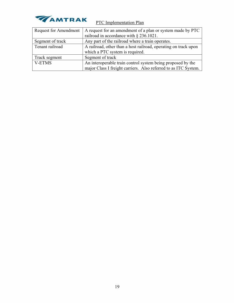
Request for Amendment A request for an amendment of a plan or system made by PTC railroad in accordance with § 236.1021.
Segment of track Any part of the railroad where a train operates. Tenant railroad A railroad, other than a host railroad, operating on track upon
which a PTC system is required. Track segment Segment of track V-ETMS An interoperable train control system being proposed by the
major Class I freight carriers. Also referred to as ITC System.

PTC Implementation Plan
20
2.0 Applicable Documents Following is a list of documents and information sources referenced in this PTC Implementation Plan:
A. Title 49 CFR Part 236, Subpart I – Positive Train Control Systems B. NORAC Operating Rules – latest edition C. General Code of Operating Rules – latest edition D. Order of Particular Applicability [FRA Docket No. 87-2, Notice No. 7] E. Amtrak Northeast Corridor Employee Timetable No. 3 – Most recent General
Order F. Amtrak Michigan Line Timetable No.2 G. Amtrak Chicago Terminal Timetable No. 3 H. Amtrak New Orleans Union Passenger Terminal Timetable No. 3 I. EP-5900 Software Management Control Plan for Processor-Based Signal & Train
Control Systems – latest revision J. SMP 38406 – Software Management Control Plan for Microprocessor Based
Train Control System, Amtrak Mechanical Department – latest revision
PTC Implementation Plan
21
3.0 Technology [§ 236.1011(a)(1)]
3.1 ACSES and ATC on the Northeast Corridor In compliance with an Order of Particular Applicability [FRA Docket No. 87-2, Notice No. 7], Amtrak installed a transponder based system designed to enforce civil speed restrictions, both permanent and temporary, and to enforce a positive stop at interlocking home signals. This system, know as ACSES, was installed and placed in service beginning in 2000 with the startup of Acela service on the Northeast Corridor. The combination of ACSES and the existing ATC system provided the basic requirements of a PTC system. The ATC system enforces all speeds associated with the signal system preventing train-to-train collisions (236.1005(a)(1)(i), and the ACSES system prevents trains from passing stop signals at interlocking home signals. ACSES enforces all permanent civil speed restrictions and temporary restrictions (slow orders) thereby preventing over speed derailments (236.1005)(a)(1)(ii). Amtrak has filed a Request for Expedited Certification (REC) and type approval for the ACSES system.
3.1.1 ACSES Overview ACSES on the Northeast Corridor (NEC) supplements the ATC system by providing additional functions and thus creating an enhanced overall train control system meeting the requirements of PTC. The primary functions of ACSES as applied to the NEC include enforcement of civil/track speeds for fixed locations such as curves, bridges, etc. as well as temporary speed restrictions. These are speed enforcement functions that are beyond the scope of the ATC CAB SIGNAL subsystem. ACSES also enforces Positive Train Stops at interlocking home signals. The ACSES system enforces permanent and temporary speed restrictions and a positive stop at home signal locations. The onboard system uses data obtained from Transponders and via a data radio network to enforce permanent and temporary speed limits. It acts on data received intermittently from Transponder and radio and it is a profile-based system where the onboard system calculates a speed profile for both warning and enforcement. If the warning profile is exceeded the engineer is given an audible alert to reduce the train speed. If the brake profile is exceeded the onboard system initiates a request for application of the train brakes that will be released when the train speed is back under the maximum speed envelope. The ACSES system util izes passive (fixed) Transponders at wayside locations, a Ground Network communications system (Safety TSR Server, Wayside Communications Controllers (WCC), Network Servers & Encoders), Base Communications Packages (BCP) along the Right Of Way (ROW), Mobile
markgriffith
markgriffith
PTC Implementation Plan
22
Communications Packages (MCP) onboard, ACSES onboard subsystem and onboard Transponder reader. The data radio system (WCC, BCP and MCP) is used to route interlocking data (route data, civil speed limits, etc.) and temporary speed limit data (start of speed restriction, length of speed restriction, speed limit, etc.) to the onboard ACSES system. The ACSES wayside Transponders are installed in ACSES territories at home signals, distant signals and at other signal, block point, or cut section locations to communicate with the onboard ACSES subsystem. The Transponders provide data to the onboard system, allowing it to determine its location and direction along the track. The Transponders also provide civil (track) speed restriction data for the territory ahead, thereby ensuring that speeds are kept safe for the various types of restrictions not caused by train occupancy (bridges, curves, etc.). ACSES works on a distance to target principle and the Transponder data includes targeting distances (distance from the Transponder to the data validity point), therefore Transponders do not need to be installed at the point at which the system uses the data (i.e. the Transponders are not installed at the speed change limit but in advance of it). The ACSES system consists of two main areas of operation, Interlocking areas and Automatic Block (between interlocking) areas. Within these two areas, the ACSES system provides civil speed and temporary speed and positive stop enforcement (at interlocking areas only). In addition, if the ATC cab signal system is inoperative or cut-out ACSES enforces a maximum cap speed of 79 MPH. The ACSES system works in conjunction with the ATC/cab signal systems used on the Northeast Corridor (NEC). The ATC CAB SIGNAL system continues to ensure “Safe Train Separation” and “Signal Speed Enforcement” while the ACSES system essentially acts as an addition to the ATC CAB SIGNAL system to provide other functions. The two systems are functionally independent. Only the operating status (cut-in and operating or cut-out) and data used for the PTS enforcement (e.g. the ACSES request for an ATC CAB SIGNAL enforcement of a PTS is shared between the two systems).
3.1.2 ACSES Functions and Architecture ACSES is a vital overlay system that performs the following main functions:
1. Enforcement of permanent speed restrictions (PSR) (civil/track speeds) for five different train types.
2. Enforcement of temporary speed restrictions (TSR) through data radio network of by use of temporary transponders.
3. Enforcement of a Positive Train Stop (PTS) at interlocking home signals. 4. Override of the PTS (PTSO) by radio if the interlocking signal status allows
the train to proceed.
markgriffith

PTC Implementation Plan
23
5. Enforcement of a civil speed received by radio based on switch alignment at interlockings. This speed corresponds to the diverging or crossover civil speed (Interlocking PSR).
6. Route Dependent speed enforcement based on exit track selection (route dependent PSR).
7. Utilizing the communications network, upload of the ACSES specific Maintenance Messages to Amtrak NEC Network Servers (ACSES Maintenance Message).
The figure below shows a basic block diagram of the ACSES System.
CETCTSR
Interface
TSR Safety Server (2 out of 3)And
Network Servers
Redundant Communications Network(WCC, MUX, DSU,…)
BCPEncoder
Or WIU
Vital Signal Circuits
DispatchingOffice
ServerEquipment
Room
WaysideInterlocking
Location
Transponders
Figure 3.1.2 ACSES System Diagram

PTC Implementation Plan
24
3.1.3 ACSES Onboard Equipment Following is a description of the main elements of the ACSES onboard equipment. A block diagram of the onboard system is shown in Figure 3.1.3. An interface between the ACSES Onboard Computer and the ATC system allows ACSES to determine if the ATC system is cut-in or cut-out. With the ATC system cut out, ACSES caps the upper speed limit to 79 mph and continues to enforce all civil speeds below 79 mph.
3.1.3.1 ACSES Onboard Computer The ACSES Onboard Computer acts upon the data received from the Transponders, Encoders and Safety TSR Server to execute the ACSES functions. The onboard ACSES subsystem uses data obtained from Transponders and via a data radio network to enforce permanent and temporary speed limits. It acts on data received intermittently from Transponder and radio and it is a profile-based system where the onboard ACSES subsystem calculates a speed profile for both warning and enforcement. If the warning curve is exceeded, the engineer is given an audible alert to reduce the train speed. If the brake curve is exceeded, the onboard ACSES subsystem initiates a request for application of the train brakes that can be released when the train speed is back under the maximum speed envelope.
3.1.3.2 ADU The ACSES Display Unit is the main means by which the ACSES system provides information to the train operator.
3.1.3.3 Transponder Reader and Antenna The Onboard Transponder Transmission equipment and passive (fixed) wayside Transponders provide the Civil Speed information and location of Home Signals for Positive Train Stop (in addition to current track, location, direction, radio channel, etc...).
3.1.3.4 MCP The Onboard (Mobile Communication Package) Radio system is used to transmit TSR, Interlocking status, and Maintenance data to/from the train. MCPs are compatible to the ATCS Specification 200.
markgriffith

PTC Implementation Plan
25
ACSESOn-BoardComputer
ADU
ATC System
MCP
Train TypeSelectorSwitch
TransponderReader/Antenna
Speed Sensor
BrakeSystem
Interface
AudibleAlarm
Figure 3.1.3 Block Diagram of ACSES On-Board System
3.1.4 Main ACSES Wayside Equipment
3.1.4.1 Transponders Civil speeds, PTS and other data are transmitted to the onboard ACSES subsystem through digital fixed transponders installed between the rails in the ACSES territories. Fixed transponders always transmit the same message, which is contained in a transponder plug (BCB - an EPROM chip inside a protective cover) programmed with the necessary local data. The Transponders are passive devices mounted between the rails at cut sections, home signals and intermediate signals as necessary. The transponders inform the Onboard ACSES subsystem of:
! An upcoming Positive Train Stop (PTS) to enforce
! When and how to contact the encoder to get the signal status and the route
! An upcoming Speed Restriction and the civil speed to enforce
! When and how to request the TSR list from the TSR server
! Its position on the railroad allowing it to enforce the TSRs received over
the radio

PTC Implementation Plan
26
! Other miscellaneous functions (begin ACSES territory, end ACSES
territory, etc.) The transponder is read when the transponder scanner antenna is directly over the wayside transponder. The Onboard ACSES is responsible for turning the onboard Transponder Transmission Subsystem ON or OFF though the TTS interface and messages. The Onboard ACSES controls this interface. Once powered, the transponder antenna will remotely energize any transponders it passes over. When energized, the transponders continually transmit its 255-bit message received at the antenna. This message is then passed to the Main Processor for interpretation. The data content is 180 bits with the rest devoted to error detection, including a 72-bit CRC used to guarantee message integrity. The 72-bit CRC is used to validate that the message received is not corrupted. The data portion of the transponder message is organized in packages, which are unique messages containing specific information for specific purpose. Each transponder set is encoded with its location. This location includes the railroad territory, chaining, the milepost and the track number. Chaining information is available from ODD numbered transponders while milepost information is available from EVEN numbered transponders. Chaining is required for enforcement of TSRs received via the communication system. Milepost is used for maintenance purpose only. Chaining values and not Milepost values are used for the purpose of enforcing TSRs since the Milepost system on the NEC is non-linear. Transponders are installed in sets ranging from 2 to 4 transponders. The transponder sets are also sometimes referred to as “Information points” containing up to 720 bits of data (180 bits x 4). The amount of data to transmit to the Onboard ACSES subsystem at a location dictates the number of transponders required for the set. A transponder set contains data for both directions of travel. Each transponder is encoded with its location. This location includes the railroad territory, chaining, the milepost and the track number. A temporary transponder may be encountered within the linking distance of two permanent transponders. Temporary transponders are used to invoke temporary speed restrictions. These temporary transponders are unlinked and do not affect the normal linking of permanent transponders. They may also be installed in the Non-ACSES territories to perform miscellaneous functions.
3.1.4.2 Encoders or Wayside Interface Units (WIU) The Encoders or WIUs interface with the signal logic at interlockings to provide status of the interlocking to the onboard ACSES subsystem (signal status (go/stop), exit track and route, civil speed limit based on switch alignment, etc). Each Encoder contains an application program that is used to define the data

PTC Implementation Plan
27
messages to be sent to the trains based on the Encoder input status. Each Encoder is interfaced to the communications network via a serial link to a BCP. Each interlocking, in ACSES territory, is equipped with an Encoder connected to the wayside data radio network. The Encoder monitors the status of the signals and switches in the interlocking. The Transponder data that informs the onboard ACSES subsystem that it is approaching an interlocking home signal also provides the onboard ACSES subsystem with the necessary information (radio channel, Encoder id, signal id, etc.) to address, via the data radio network, the appropriate Encoder. The Encoder responds to this request message with the appropriate data for the home signal being approached. The encoder will send a data message, upon request, to the Onboard ACSES subsystem informing it that the home signal is at STOP or not. The Onboard ACSES subsystem uses this information to release the PTS if the signal is not at Stop. The encoder message also contains other data that includes:
! The track the train will exit the interlocking on.
! The civil speed limit for the selected route.
! C signal status in “cab signal without wayside signal” territory.
! Distance to the next interlocking (LoMA) if there is not sufficient distance from the exit of the first interlocking to the PTS target of the next interlocking.
! The distance from the point where the train diverges from the entrance
track to the point where the train converges on the exit track.
! A list of the tracks the train will cross during its move through the interlocking.
This data on the status of the interlocking route is required by other functions of ACSES such as TSR, Interlocking PSR and Route Dependent PSR. The Encoder data will also contain information about an adjacent interlocking home signal if the distance between the home signals is less than safe braking distance (this is called the LoMA or limit of movement authority distance). This data is used to allow the onboard ACSES subsystem to anticipate the next home signal and generate the correct profile to insure that, if necessary, a stop is enforced.
3.1.4.3 Safety TSR Server The wayside ACSES system also features a TSR Server(STS). The TSR Server is responsible to safely manage the TSR data. The TSR information compiled by the NEC dispatchers is converted to digital data and transmitted to the TSR Server. The TSR data includes the location of the TSR (railroad & line, track, start
PTC Implementation Plan
28
milepost), the length of the restriction, and the speed limit of the restriction for passenger and freight trains. Only two restriction speeds are provided in a TSR. All passenger trains (train types A, B, C, and D) use the passenger train speed restriction limit and all freight trains (type E) use the freight train speed restriction limit. The STS manages the addition and removal of TSR data. The Transponder data that causes the onboard ACSES subsystem to request Encoder data also causes the onboard ACSES subsystem to request TSR data. This request is routed by the wayside radio system to the TSR Server. The TSR Server responds with all the TSRs for all the tracks, in the train’s direction of travel only, for the area covered by the local radio base station plus the next two radio base stations. The Onboard ACSES subsystem uses this data along with its location, and direction of travel to enforce these restrictions in exactly the same manner as it enforces a PSR. In all cases the onboard ACSES subsystem enforces the lowest speed limit required for each point along the track. The Safety TSR Server (STS) is located at a central location and manages Temporary Speed Restriction data for all ACSES territories. The STS is responsible for maintaining the list of TSRs and providing them to the trains upon request. Amtrak plans to install additional TSR servers so that one server set is allocated to each of the three NEC dispatching centers.
3.1.4.4 Network Servers The Network Servers (NS) are located next to the STS. The Network Servers are responsible for the communication interface between the ATCS specification 200 communications system, the TCP/IP communications link to CETC, and the serial interface to the STS. It acts as a gateway between the STS and the external system interfaces. The Network Servers also receive the ACSES-specific Maintenance Messages intended for Amtrak maintenance personnel. The Network Servers also log all transactions and provide a means for the archiving of this data.
3.1.4.5 BCPs Wayside Base Communication Package Radio system used to transmit TSR, Interlocking, and Maintenance data to/from the train. They are installed in interlocking areas. One BCP can interface with more than one encoder. BCPs are compatible to the ATCS Specification 200.
3.1.4.6 Wayside Communications Controllers The Wayside Communications Controllers (WCC) are redundant communications equipment installed at a central location that control message routing and delivery between equipment. Communications links between the WCCs and the BCPs are fully redundant to increase the availability of the ACSES radio functions. WCCs are compatible to the ATCS Specification 200.

PTC Implementation Plan
29
3.1.5 ACSES Train Types There are five different types of train configurations on the NEC that are considered as part of the ACSES implementation. They are defined as follows in the NEC timetable:
! Type A - High Speed Train set with tilting.
! Type B - High Speed Train set without tilt operating or trains meeting AEM-7 w/Amfleet braking curve.
! Type C – Other passenger trains meeting Amtrak CE-205 braking curve.
! Type D – Mail and Express trains (no longer being operated).
! Type E – Freight trains.
These train types correspond to different sets of operating speeds of the Amtrak timetable. They also have different braking profiles. Moreover, certain vehicles and locomotives are of multi-purpose usage and can operate as different train types depending on the nature of the train's mission. ACSES provides overspeed protection specific to each NEC train type. The onboard ACSES subsystem is set to one of the five train types when originally configured, or before a run via the Train Type Selector Switch (TTSS) installed in the multi-purpose vehicles, and uses the data from the transponders and radio that corresponds to its train type. It also uses a different braking profile according the train type set for the vehicle.
3.1.6 ACSES Data Communication System Concepts The radio system allows exchange of data between the Onboard ACSES and the wayside equipment for dynamic updates of data. The radio data for the NEC application include:
! Status of interlocking signals and route
! Temporary Speed Restriction data
! Maintenance data ACSES on the NEC was implemented using ATCS 200 900 MHz, which proved to be adequate for the NEC needs. However, the ACSES application is not dependant on the communication system technology, as the data radio and comms system is only a functional message conduit for ACSES application. The integrity of the data transmission is not dependent on ATCS communications

PTC Implementation Plan
30
since the ACSES safety- critical application layer was designed independently from the non-vital communication application layers. For example, the application messages are self-protecting and are of the same basic format as the transponder messages, which is a proven format. Additional "checks" are performed onboard to ensure protection from duplicate messages, against data storage and against communication message routing errors in the non-vital communication system. Amtrak intends to use a 220 MHz data radio for future ACSES expansion but this will not change the message format in any way. For radio communications, the Onboard is the master of the system from a train control application standpoint as it initiates all requests for data. It will initiate the requests based on the information provided by the transponders. The wayside TSR Server and Encoders only respond to Onboard requests for data. The NEC data radio transmission system is non-deterministic and, by design, ACSES is capable of accepting responses to radio requests that may be few communications cycles old. Since ACSES received data from transponders and is paired to the ATC system, the requirements for radio communications are not as critical as other communications-based systems, which require radio data to be updated frequently (often continuously) onboard. The concept for the NEC is that ACSES needs to tolerate missed radio messages. The keys are that several opportunities to obtain the data before it is required are provided and, once data is received onboard, it will remain valid for a certain time until it is declared too old to maintain safety, at which point the radio data received is deleted with ACSES reverting to the appropriate safe state. Encoders are installed at every interlocking but ATCS BCP radios are installed at every interlocking “area”, which may include one or several interlockings located close together. The BCPs are connected to the centrally controlled ATCS Wayside Communications Controllers (WCC) that interfaces to the TSR server.
3.1.7 Infrastructure Data The infrastructure data (civil speeds, PTS target, milepost, chaining, track number, etc.) is loaded directly in the transponder program. Data is also loaded in the Encoder program located at the interlockings. This encoder data includes crossover or diverging speed at interlockings, exit track data, discrete input configuration, etc. The Safety TSR Server (STS) also hosts a database. This database contains the infrastructure information required by the TSR server (track layout, Milepost/Chaining conversion, grade, etc.). The database does not contain civil speed and other permanent speed restriction. The transponder and encoder data is contained in a database (one database per railroad line segment) that is stored on a PC. It is accessed and modified using a specific application named the ACSES Programming Tool (APT) developed by Alstom. The APT is also used to program transponders and encoders. The STS data is also
markgriffith
warrenhavens
Text Box
[The frequency is not the critical element in PTC. It is the data messaging, which can be on any frequency]
PTC Implementation Plan
31
contained in a database (an excel table) named the Fixed Database and the Fixed Database Tool is the tool used to convert the Excel file to the Motorola S3 format for programming the data on the memory cards of the STS.
3.1.8 ACSES Safety ACSES is comprised of:
! Onboard System (vital)
! Transponders
! Encoders (vital)
! Safety TSR Server (vital)
! Network Servers
! Control Center application for TSR entry
! Centralized maintenance system
! Communications system (ATCS compliant radios and network) The vital ACSES equipment includes the Onboard system, the Encoder and the Safety Server.
To perform its functions ACSES also uses safety critical data. Transponder, Encoder and Safety TSR Server application data is safety-critical. In addition, the data message exchanged between the vital equipment, via the comms system, is safety critical. Note that the transponders are not vital components. The vitality of the data transfer is ensured by self-protecting data (with use of large "check words") combined with other consistency checks performed by the vital components on the data received. The same principle is used for the radio transmission. The data design and installation in the field follows a strict process to ensure the data is correct, accurate and ensures safe for operation. The interface between the Safety Server and the non-vital Control Center application for the TSR addition and deletion obeys a rigorous select-check-execute process, but the correctness of the data is still under the responsibly of the dispatcher as ACSES cannot evaluate the correctness of the information entered by the Dispatcher fully on its own.

PTC Implementation Plan
32
3.2 ITCS on Amtrak’s Michigan Line
3.2.1 General Description The ITCS is a communication-based signaling system designed as a vital overlay to an existing signal system. It provides enforcement of signal indications, civil speed limits, and temporary slow orders. In addition, it provides advanced start of public crossings and Restricted Speed enforcement over hand-operated switches. ITCS monitors the existing signal system as a basis for determining permissible actions, and uses a radio frequency (RF) data link with a vital communication protocol to send wayside status information to the trains. Enforcement of indications and the speed limit are performed vitally by an onboard computer (OBC). The OBC stores the track information in database files, which includes civil speed limits of the ITCS territory, grade along the tracks, a list of devices and their locations that may need to be communicated to the train, as well as other information. The train's location on the track is determined by the location system utilizing the Global Positioning System (GPS) and axle tachometers. Train’s location is compared to the points in the database file to determine the required actions. The Wayside components monitor signal aspects, switch positions, crossing warning systems, and other equipment as required. This information is relayed to the train OBC over the RF network as a list of device statuses. The OBC interprets the statuses, and enforces all signal indications, speed limits, and other required braking. At crossings, an additional feature allows an OBC on a train traveling at high speed to radio ahead to a crossing for an advance start of the warning system. The OBC must receive an acknowledgment from the crossing, verifying the proper operation of the crossing warning system, before the train can proceed at high speed through the approach circuit. The OBC calculates the most restrictive speed limit based on the inputs from the databases, the wayside devices, the train’s location system, and the train’s speed. The OBC then determines when a reduction in speed is required for an upcoming device or speed limit. If a reduction is needed, the OBC calculates a braking profile for the train, and displays the necessary information for the driver, who must slow the train to an appropriate speed. If the train reaches a point where the brakes must be applied to meet the target speed, the OBC applies a penalty brake. The OBC also monitors the train’s current speed and compares it to the maximum allowed speed. If the train accelerates above the allowed speed limit, the OBC warns the operator. A penalty brake results when a critical speed is exceeded. An office terminal allows the dispatcher to enter Temporary Slow Orders (TSO) into the system. These restrictions are sent to the Wayside Interface Unit (WIU)-Servers, which in turn transmit the information to the OBC as the equipped trains pass through ITCS Territory.

PTC Implementation Plan
33
Michigan/Amtrak ITCSSystem Block Diagram
CLD
OBC
OFFICESYSTEM
WIU Server
IntermediateSignal WIU
Control PointWIU
Hand OperatedSwitch WIU
Public CrossingWIU
OBC - On Board ComputerWIU - Wayside Interface Unit
CLD- Compact Locomotive Display
GPSSatellites
TD220Radio
TD220Radio
GPSRIMs
GPS RIM - Global Positioning System Receiver Interface Module
OnboardTrain
Controls
WLAN
ExistingRelayLogic
Signal Indications,Track Circuit Input
SignalIndications,TrackCircuit Inputs, OS
Track Circuits,Normal / ReverseSwitch Positions
Normal / ReverseSwitch Positions
GPSReferenceStation -Novatel
GPSSatellites
GPS RIMReference
Station-Motorola
OWL
OWL - Office / Wayside LinkSSR-Spread Spectrum Radio
TWCNetwork
On-BoardEquipment
SpeedSensors
SSR
SSR
SS
RSS
R
SSR
Modem
To Other WIUServers
To Other WIUs
Modem
CrossingWarningDevice
Figure 3.2.1-1 Block Diagram of ITCS Components
markgriffith
markgriffith

PTC Implementation Plan
34
Figure 3.2.1-2 ITCS Overview
3.2.2 ITCS Components
3.2.2.1 On Board Computer (OBC) The OBC consists of two logical functions, the Automatic Train Protection (ATP) function, and the Location Processing function. The ATP function performs communication tasks, determines the train's speed and provides vital braking enforcement. The Location Processing function determines the location of the train.
3.2.2.2 GPS Receiver Interface Module (GPSRIM) Two GPSRIM collect data from the GPS satellites, and, using differential correction data originated by the GPS Reference Stations, provide longitude, latitude, and speed data to the Location Processing function of the OBC.
3.2.2.3 Compact Locomotive Display (CLD) The CLD displays information from the OBC to the train driver, provides audible alarms for various warnings, and provides inputs for driver control of the on-board system. An LED-based display provides information to the train driver. This Compact Locomotive Display (CLD) communicates with the OBC via the CAN protocol and an RS-485 port. The CLD also contains several user input switches, and an alarm for audible indication of important events to the locomotive crew. At a minimum, the CLD displays the following information when appropriate:
Dispatch Center
Temporary Slow Orders and Wayside Status Messages to
Train
ITCS Server Location WIU Location
GPS Satellites
Temporary Slow Orders

PTC Implementation Plan
35
! Current speed ! Current speed limit
! Current target speed
! Current Time to Penalty
! Distance to current target
! Current target type
! Train Location, to the nearest 1/10th mile
! The Type of Train
3.2.2.4 Train to Wayside Communications Network (TWC) The TWC Network provides a bi-directional data communications link between the on-board equipment and the wayside equipment. Each OBC and WIU-Server in the ITCS system has an ITCS address. The TD220 radio interprets an ITCS address in order to direct a received message to the intended device. The TD220 radio is considered part of the TWC network. An interface between the TD220 and the NovAtel (Wayside only) provides a one pulse per second output and time measurement to synchronize the TD220 radio for Time-Division-Multiplexing (TDM) operation. The on-board TD220 radio does not require GPS data for timing. The TWC must provide a reliable link for the OBC and WIU-Server beyond the boundary of the WIU-Server’s WLAN. The exact distance from the WIU-Server depends on the speed limits in the area and the boundary of the WIU-Server’s region.
3.2.2.5 Wayside Interface Unit (WIU) The WIU interfaces to new or existing equipment along the track. It may provide vital inputs, outputs, or both, and has the capability of running application logic equations. The WIU communicates with the WIU-Server over the WLAN.
3.2.2.6 Wayside Interface Unit – Server (WIU-Server) In addition to performing the basic WIU functions, a WIU-Server provides an interface to the TWC network, and is the master device on a WLAN. The WIU-Server also contains an interface to the Office Terminals through the Office to Wayside Link. At each server are two GPS reference stations. The GPS antenna position for each reference station is surveyed for accuracy to within one foot. The reference stations provide the differential corrections to the GPSRIM pairs located on the trains while the trains are within the server’s region. Each reference station provides correction data for one half of each train’s GPSRIM pair. One of the reference stations also provides UTC time to the WIU-Server for time tagging log information and a highly accurate time base
markgriffith
markgriffith
markgriffith

PTC Implementation Plan
36
to the TD220 radio for synchronizing its time-division-multiplexed (TDM) transmissions over the TWC.
3.2.2.7 Terminal Server The Terminal Server is a special type of server that exists at certain locations, typically near a terminal, to aid the OBC in performing its Departure Test and to transmit the entire set of ITCS Databases to the OBC.
3.2.2.8 Wayside Local Area Network (WLAN) The WIUs and WIU-Server communicate over a Spread Spectrum Radio (SSR) link and exchange messages containing the status of the wayside equipment as monitored by the WIU and the information necessary for ITCS control of the crossing warning systems.
3.2.2.9 Office to Wayside Link The Office to Wayside Link provides a bi-directional data communications link between the Office Terminal and the WIU-Servers.
3.3 Amtrak’s Implementation of V-ETMS 49 CFR §236.1011(a)(1) requires that the PTCIP describe the functional requirements that the proposed PTC system must meet. As required by 49 CFR 236, Subpart I, §236.1013, the PTCDP describes how V-ETMS® satisfies the mandated requirements for PTC systems as outlined in §236.1005. Amtrak will be using the PTC Development Plan (“PTCDP”) prepared by Wabtec Railway Electronics (“WRE”), CSX Transportation (“CSXT”), Norfolk Southern Railway, and Union Pacific Railroad (“UPRR”) which was submitted to the FRA on March 24, 2010 (FRA Docket 2010-0028) for review and approval. The PTCDP was jointly submitted for FRA Type Approval as set forth under 49 CFR Part 236, Subpart I §236.1009(b) and included documentation as required by §236.1013. The Vital Electronic Train Management System (V-ETMS®) Development Plan describes development of the WRE Vital Electronic Train Management System (V-ETMS), an interoperable PTC system developed in compliance with requirements and standards defined through the Interoperable Train Control (“ITC”) industry effort (Amtrak participated in ITC committee meetings). V-ETMS is a locomotive-centric, vital train control system designed to be overlaid on existing methods of operation and provide a high level of railroad safety through enforcement of a train’s authorized operating limits, including protection against train-to train collisions, derailments due to overspeed, unauthorized incursion into work zones, and operation through main track switches in improper position. The V-ETMS system is designed to support different railroads and their individual methods of operations and is intended to be implemented across a broad spectrum of railroads without modification. This design approach supports interoperability across railroads as V-ETMS equipped locomotives apply consistent warning and enforcement rules regardless of track ownership.
markgriffith
markgriffith

PTC Implementation Plan
37
An overview of the V-ETMS system, its primary functions, the architecture of the PTC system(s) being deployed, and a high level description of the functionality of the PTC system, subsystems, and interfaces are all found in the PTCDP. Specifically, these areas are addressed in the following sections: !
Section 3, V-ETMS Description, which provides a complete description of the V-ETMS system including a list of all product components and their physical relationships in the subsystem or system, as required by 49 CFR 236 Subpart I §236.1013(a)(1). 3.1 LOCOMOTIVE SEGMENT 3.2 OFFICE SEGMENT 3.3 WAYSIDE SEGMENT 3.4 COMMUNICATIONS SEGMENT 3.5 DATA FLOW 3.6 V-ETMS PRIMARY FUNCTIONS
Section 4, PTC Architecture, which describes how V-ETMS architecture satisfies safety requirements as required by 49 CFR 236 Subpart I §236.1013(a)(4). 4 PTC Architecture 4.1 LOCOMOTIVE SEGMENT 4.1.1 V-ETMS Train Management Computer 4.1.2 Computer Display Unit 4.1.3 GPS Receiver 4.1.4 Locomotive Event Recorder 4.1.5 Train Control Application 4.1.6 Business Applications 4.2 OFFICE SEGMENT 4.2.1 V-ETMS Office Segment 4.2.2 Office Server Platform 4.2.3 Office Segment External Interfaces 4.3 WAYSIDE SEGMENT 4.3.1 WIU Technology 4.4 COMMUNICATIONS SEGMENT 4.4.1 The Messaging System 4.4.2 Wireless Networks
The Concept of Operations as required by §236.1013(a)(3) is covered in Section 7 of the PTCDP. This portion of the PTCDP addresses each of the PTC functional requirements as called out in the Subpart. While the entire Concept of Operations provides a thorough understanding of the system’s ability to meet the requirements, for the purpose of this document, each requirement will be addressed with a reference within the Vital Electronic Train Management System (V-ETMS®) Development Plan, Section 7, Concept of Operations as follows:
§ 236.1005 Requirements for Positive Train Control systems.

PTC Implementation Plan
38
(a) PTC system requirements. Each PTC system required to be installed under this subpart shall: (1) Reliably and functionally prevent: (i) Train-to-train collisions—including collisions between trains operating over rail-to-rail at-grade crossings …
! Section 5.4.1 Movement Authority Provided by Mandatory Directive ! Section 5.4.2 Wayside Signals ! Section 5.4.3 Cab Signals ! Section 5.4.4 Reverse Movement ! Section 5.4.5 Switching Mode ! Section 5.4.6 Entry to V-ETMS Territory ! Section 5.4.7 Exit from V-ETMS Territory ! Section 5.4.8 Yard Limits ! Section 5.11 Warning and Enforcement ! Section 5.11.2 Predictive Warning and Enforcement ! Section 5.11.3 Restrictive Speed Enforcement
! Rail-to-rail crossings-at-grade that have one or more PTC routes
intersecting with one or more routes without a PTC system must have an interlocking signal arrangement in place developed in accordance with subparts A through G of part 236 and a PTC enforced stop on all PTC routes. FRA has also determined that the level of risk varies based upon the speeds at which the trains operate through such crossings, as well as the presence, or lack, of PTC equipped lines leading into the crossing. Accordingly, if the maximum speed on at least one of the intersecting tracks is more than 40 miles per hour, then the routes without a PTC system must also have either some type of positive stop enforcement or a split-point derail on each approach to the crossing and incorporated into the signal system, and a permanent maximum speed limit of 20 miles per hour.
(ii) Overspeed derailments, including derailments related to railroad civil engineering speed restrictions, slow orders, and excessive speeds over switches and through turnouts; ! Section 5.4.8 Yard Limits ! Section 5.5 Speed Limits and Restrictions ! Section 5.5.1 Permanent Speed Restrictions ! Section 5.5.2 Temporary Speed Restrictions ! Section 5.5.3 Track Authority Speed Restrictions ! Section 5.5.4 Consist or Lading Speed Restriction ! Section 5.11 Warning and Enforcement ! Section 5.11.1 Reactive (Overspeed) Warning and Enforcement ! Section 5.11.2 Predictive Warning and Enforcement ! Section 5.11.3 Restricted Speed Enforcement

PTC Implementation Plan
39
(iii) Incursions into established work zone limits without first receiving appropriate authority and verification from the dispatcher or roadway worker in charge, as applicable and in accordance with 49 CFR part 214
! Section 5.6 Work Zones ! Section 5.11 Warning and Enforcement ! Section 5.11.2 Predictive Warning and Enforcement
(iv) The movement of a train through a main line switch in the improper position as further described in § 235.1005(e).
! Section 5.10 Route Integrity Protection ! Section 5.10.1 Monitored Hand-Operated Switches ! Section 5.10.2 Switches in Signaled Territory ! Section 5.11 Warning and Enforcement ! Section 5.11.2 Predictive Warning and Enforcement
(2) Include safety-critical integration of all authorities and indications of a wayside or cab signal system, or other similar appliance, method, device, or system of equivalent safety, in a manner by which the PTC system shall provide associated warning and enforcement to the extent, and except as, described and justified in the FRA approved PTCDP or PTCSP, as applicable;
! Section 5.4.2 Wayside Signals ! Section 5.4.3 Cab Signals"! Section 5.10.2 Switches in Signaled Territory ! Section 5.10.3 Other Monitored Devices ! Section 5.11 Warning and Enforcement ! Section 5.11.1 Reactive (Overspeed) Warning and Enforcement ! Section 5.11.2 Predictive Warning and Enforcement ! Section 5.11.3 Restrictive Speed Enforcement
(3) As applicable, perform the additional functions specified in this subpart;
(4) Provide an appropriate warning or enforcement when: (i) A derail or switch protecting access to the main line required by § 236.1007, or otherwise provided for in the applicable PTCSP, is not in its derailing or protecting position, respectively; {Applies to high speed passenger lines}
! Section 5.4.2 Wayside Signals ! Section 5.10.3 Other Monitored Devices ! Section 5.11 Warning and Enforcement ! Section 5.11.2 Predictive Warning and Enforcement
(ii) A mandatory directive is issued associated with a highway-rail grade crossing warning system malfunction as required by §§ 234.105, 234.106, or 234.107;
! Section 5.7 Malfunctioning Highway Grade Crossing Warning Systems
! Section 5.11 Warning and Enforcement
PTC Implementation Plan
40
! Section 5.11.2 Predictive Warning and Enforcement
(iii) An after-arrival mandatory directive has been issued and the train or trains to be waited on has not yet passed the location of the receiving train;
! Section 5.4.1.1 Track Warrant Control
(iv) Any movable bridge within the route ahead is not in a position to allow permissive indication for a train movement pursuant to § 236.312; and
! Section 5.4.2 Wayside Signals ! Section 5.10.3 Other Monitored Devices ! Section 5.11 Warning and Enforcement ! Section 5.11.2 Predictive Warning and Enforcement
(v) A hazard detector integrated into the PTC system that is required by paragraph (c) of this section, or otherwise provided for in the applicable PTCSP, detects an unsafe condition or transmits an alarm; and
! Section 5.4.2 Wayside Signals ! Section 5.10.3 Other Monitored Devices ! Section 5.11 Warning and Enforcement ! Section 5.11.2 Predictive Warning and Enforcement
(5) Limit the speed of passenger and freight trains to 59 miles per hour and 49 miles per hour, respectively, in areas without broken rail detection or equivalent safeguards.
! Section 5.5.1 Permanent Speed Restrictions ! Section 5.11 Warning and Enforcement ! Section 5.11.1 Reactive (Overspeed) Warning and Enforcement
3.3.1 Application of V-ETMS on Amtrak V-ETMS will be installed on portions of Chicago Union Terminal, portions of New Orleans Union Passenger Terminal and on portions of the Northeast Corridor. In Chicago and New Orleans V-ETMS will operate without cab signals and will be fully compatible with all the carriers using the same system. On the Northeast Corridor ACSES and ATC will be the primary PTC system with V-ETMS as an additional vital overlay for interoperability with the freight carriers and with some MARC and VRE commuter trains. A back office server will hold the track database and will handle temporary speed restriction data. WIUs installed at each interlocking will function as an encoder for ACSES trains and a V-ETMS WIU for V-ETMS equipped trains. Each system will have its own unique message format and the WIU will be able to format a proper message for either an ACSES train or a V-ETMS train. All carriers operating on the NEC will be required to have on-board cab signal equipment which will provide signal aspect status for train separation therefore a WIU will not be required for every location. WIUs will be installed only at interlockings in the same

PTC Implementation Plan
41
manner as ACSES. A V-ETMS 220 MHz data radio system will be installed to deliver information to and from the V-ETMS equipped trains. Amtrak plans to equip the following territory on the NEC for V-ETMS operation:
! Between CP Virginia and A interlocking in Washington, DC for VRE trains and Amtrak trains operating over CSX south of Washington.
! Washington Union Terminal to Lane interlocking in Newark, NJ for CSX, NS and
Conrail freight operation and also for some MARC commuter trains and some Amtrak diesel operated traffic.
! Between Harrisburg, PA and Philadelphia for NS freight operation and for
Amtrak diesel operated trains coming onto the NEC.
! Between New Haven, CT and Springfield, MA for Connecticut Southern Railroad freight operation.
markgriffith
PTC Implementation Plan
42
4.0 Compliance [§ 236.1011(a)(2)] This section describes how Amtrak intends to comply with § 236.1009(c) and § 236.1009(d). It is divided into three parts corresponding to the three PTC systems which Amtrak will install and operate.
4.1 ACSES/ATC System on the Northeast Corridor The ACSES system was installed by an Order of Particular Applicability [FRA Docket No. 87-2, Notice No. 7]. It is a vital overlay system that provides the additional PTC functionality not provided by the signal and ATC system. Amtrak is submitting a Request for Expedited Certification (REC) and type acceptance for the ACSES system as described in § 236.1031(a)(3). The REC document provides a detailed description of the ACSES system which is the equivalent of a PTCDP as required by § 236.1013 along with reference to materials previously submitted to FRA which constitute the equivalent of a PTCSP as required by § 236.1015. Once FRA grants a type approval for the system its validity will automatically be ensured since the system is already implemented on the NEC.
4.2 ITCS System on Amtrak’s Michigan Line Amtrak installed the ITCS system on portions of its Michigan Line under a train control demonstration grant in cooperation with FRA, the State of Michigan and General Electric Transportation Systems (originally Harmon Industries). ITCS is a vital overlay system. FRA has been very involved with the development and testing of this system. Currently Amtrak is operating passenger trains at 95 mph under an FRA waiver.
Amtrak is submitting a Request for Expedited Certification (REC) and type approval for the ITCS system as described in § 236.1031(a)(2). This system has been in operation for over 5 years and has received an assessment of Verification and Validation from an independent third party (Battelle Laboratories). The system is being expanded to include the entire territory between Porter, IN (MP 240.7) and Kalamazoo, MI (MP 143.2) owned by Amtrak. The REC document provides a detailed description of the ITCS system which is the equivalent of a PTCDP as required by § 236.1013 along with reference to materials previously submitted to FRA which constitute the equivalent of a PTCSP as required by § 236.1015. Once FRA grants a type approval for the system its validity will automatically be ensured since the system is already implemented on Amtrak’s Michigan Line.
4.3 Amtrak’s Implementation of V-ETMS Outside the Northeast Corridor most of Amtrak’s trains operate over other railroads, mostly the Class I carriers. In order to be interoperable with these carriers Amtrak will install the Vital Electronic Train Management System (V-ETMS) on most of its diesel locomotive fleet operating outside the NEC. Amtrak property outside the NEC and the
PTC Implementation Plan
43
Michigan Line where PTC is required will be equipped with V-ETMS wayside and office equipment as well. This territory includes, portions of the Chicago Union Station terminal area, portions of the New Orleans Union Passenger Terminal, and a short track segment between CSX’s CP Virginia and “A” interlocking in Washington Union Terminal in Washington, DC. On these areas of Amtrak property V-ETMS will be the only type of PTC system. In order to accommodate carriers that operate on the NEC but primarily operate in V-ETMS territory, Amtrak will provide a V-ETMS overbuild in ACSES territory that will allow operation of those trains without them having to be dual equipped with V-ETMS and ACSES as described in Section 3 of this document.
4.3.1 Utilization of Existing Type Approval and/or PTCDP The Class I North American freight carriers are working together to develop an interoperable train control system. They have jointly filed a PTCDP for the Vital Electronic Train Management System (V-ETMS) (FRA Docket 2010-0028) and are requesting a type approval for this system. Amtrak has participated on the ITC Committees formed by the Class I carriers and intends to utilize their PTCDP and Type Approval for the V-ETMS system.
4.3.2 Certifying the Validity of Type Approval § 236.1013(c) states that “Each Type Approval shall be valid for a period of 5 years, subject to automatic and indefinite extension provided that at least one PTC System Certification using the subject PTC system has been issued within that period and not revoked.” Amtrak intends to complete its implementation of V-ETMS before that 5 year period expires. We will be working closely with the Class I carriers as well as commuter railroads such as Metra in Chicago and will be kept apprised of any changes or modifications to their plans. Amtrak will maintain its Type Approval status.
4.3.3 Handling of Unique Aspects of the PTCDP and Type Approval Amtrak does not foresee any significant variances in technology from the V-ETMS systems applied to the freight railroads. Amtrak has worked closely with Norfolk Southern Railroad (NS) to address interoperability issues for NS freight trains operating on the NEC. All carriers operating on the NEC are currently required to be equipped with cab signal systems including NS freight trains. CSX, NS and the UP all have cab signal territory on their railroads and intend to use cab signal equipment in combination with V-ETMS equipment in their PTC implementations. Outside the NEC it is not anticipated that there will be any significant variances or unique aspects of V-ETMS implementation. Amtrak locomotives operating in V-ETMS territory will be equipped with the same on-board equipment as the freight carriers. It is recognized that there will be differences in software configurations of the on-board equipment since braking algorithms and braking

PTC Implementation Plan
44
procedures will be different for passenger equipment. These software configurations will be documented and fully tested. For any necessary deviations or variances from the approved freight PTCDP, Amtrak will prepare a document that will amend or replace language in that PTCDP.
4.3.4 Deliverables Amtrak will supply the following deliverables to FRA to support a petition for PTC System Certification:
! A PTC Implementation Plan (PTCIP) ! Reference numbers for a PTC Development Plan (PTCDP) and Type Approval
submitted by the Class I carriers ! Amendments to the PTCDP (if applicable) ! A PTC Safety Plan (PTCSP) ! A detailed description of braking algorithms and any other software configuration
variables unique to Amtrak’s on-board systems.
4.4 Project Risk Assessment The implementation of PTC on Amtrak will have a number of risks that are dependent on factors that are known and unknown. Risks will be assessed using the following ratings: Likelihood Ratings
Rating Description Almost Certain (5) There is little doubt that the event will occur Likely (4) There is a strong possibility that the event will occur Possible (3) There is a possibility that the event will occur Unlikely (2) There is a slight possibility that the event will occur Rare (1) It is highly unlikely that the event will occur Impact Ratings
Rating Examples Catastrophic (5) Fatal to project preventing completion or introducing long term
delay Has a large financial impact to project budget
Major (4) Significant delay to project schedule Significant financial impact to project budget
Moderate (3) Has some impact on project schedule Has some impact on project budget
Minor (2) Has small impact on project schedule Has small impact on project budget
Insignificant (1) Minimal impact on project schedule Minimal impact on project budget

PTC Implementation Plan
45
The risk rating will be obtained by multiplying the Impact Rating by the Likelihood Rating. A rating of Critical (20 or more) or High (10 or more) will require very careful management and monitoring and will require an up front contingency plan. A rating of Medium (6 - 9) will require management strategies to be developed and implemented by the Project Manager. A rating of Low (1-5) is an acceptable risk level and will be managed by normal control procedures.
4.4.1 Risks to PTC Implementation For the ACSES and ITCS systems there is little risk for Amtrak’s success. Both of these systems are currently in service and Amtrak has many years experience in their operation. Amtrak currently has GE Transportation Systems under contract to complete the installation of ITCS on the Michigan Line. This work is scheduled to be completed by February 2011. If the project is not completed on time, there is plenty of time to recover and complete the work before the mandated deadline of December 31, 2015. Likelihood of not completing the work on schedule: Possible (3) Impact: Moderate (3) Risk Rating: Medium (9); Mitigation: Carefully monitor schedule and resolve conflicts quickly. Amtrak currently has Alstom under contract to design the ACSES system for the remaining portions of the NEC. The Amtrak locomotive fleet operating on the NEC already has ACSES equipment installed and operating on a daily basis. All carriers operating on the NEC between New Haven and Boston also are equipped with ACSES and are operating with it on a daily basis. Amtrak intends to complete its wayside installation on the NEC by December 31, 2012. If the project encounters problems, there should be plenty of time to recover and complete the work before the mandated deadline of December 31, 2015. Likelihood of not completing the work on schedule: Possible (3) Impact: Moderate (3) Risk Rating: Medium (9); Mitigation: Carefully monitor schedule and resolve conflicts quickly. Amtrak intends to change the ACSES data radio system from the current 900 MHz system to a new 220 MHz data radio for better performance. The risk of this change is minimal but if this solution either does not work or threatens to delay the project beyond the mandated deadline, we can fall back to the 900 MHz radio that we already know will work. Likelihood of solution not working or adding significant delay: Unlikely (2) Impact: Major (4) Risk Rating: Medium (8); Mitigation: Carefully monitor progress and resolve conflicts quickly. There will be interoperability risks for the commuter railroads operating on the NEC that intend to install ACSES on their own railroads. This risk is primarily theirs but Amtrak will try to mitigate these risks by working closely with them as they develop and
markgriffith
markgriffith
markgriffith
markgriffith
markgriffith

PTC Implementation Plan
46
implement their systems. Amtrak has already provided detailed information to them and is working with them to set standards to ensure seamless interface between our systems and properties. Amtrak will work with them to test their equipment on the NEC to prove interoperability. Likelihood of not achieving interoperability: Unlikely (2) Impact: Catastrophic (5) Risk Rating: High (10); Mitigation: Tight coordination with commuters throughout the development of their systems. Aggressive testing will be required for compatibility and interoperability. The biggest risk that Amtrak faces is the implementation of the V-ETMS system. V-ETMS is not widely implemented and there is very little, if any, operating experience with it. It will not be the primary PTC system for most of Amtrak’s property. In fact, very little of Amtrak’s property will have V-ETMS as its primary PTC system. Since there is little wayside equipment for Amtrak to install the risk of not completing this work on time is extremely small, especially on Amtrak property outside the NEC. Likelihood of V-ETMS not being completed on time: Rare (1) Impact: Major (4) Risk Rating: Low (4); Mitigation: Schedule WIU installation and BOS installation early and coordinate closely with tenant railroads. On the NEC, Amtrak plans to utilize the same wayside interface unit (WIU) that is used for ACSES as the WIU for V-ETMS. The WIU will be able to respond to an ACSES train with an ACSES message format and a V-ETMS train with a message format used by that system. There is a risk that this will not work reliably. If this proves to be a problem, Amtrak can install two WIU’s at each interlocking, one for ACSES and one for V-ETMS. Likelihood that WIU will have a negative impact on schedule: Possible (3) Impact: Moderate (3) Risk Rating: Medium (9); Mitigation: Install test WIU early. Carefully monitor progress and resolve problems early. The risk outside the NEC is that interoperability issues will delay the final implementation of the system. This will largely be beyond Amtrak’s control as Amtrak is not the driving force behind the V-ETMS system. Amtrak can mitigate its risks in this area by working closely with the Class I carriers and equipping test trains that can be used to flush out the interoperability issues early in the process. Other than technical risks, the other major risk to Amtrak is that funding will not be available to complete its implementation of PTC on time or that it will not be able to fund PTC on its host carriers where PTC will be required only because of the presence of Amtrak passenger trains. These risks are beyond the scope of this document and will have to be addressed through other channels.

PTC Implementation Plan
47
5.0 Interoperability [§ 236.1011(a)(3)] This section describes how the PTC systems on Amtrak will provide interoperability with its tenant railroads. It is divided into three parts corresponding to the three PTC systems which Amtrak will install and operate. Appendix A contains interoperability agreements signed by both Amtrak and its tenant carriers.
5.1 Northeast Corridor and Feeder Lines
5.1.1 Agreement Provisions Relevant to Interoperability [§236.1011(a)(3)(i)] Amtrak is the host railroad to the following tenants on the Northeast Corridor:
! Virginia Railway Express (VRE) operating into Washington Union Terminal (WUT) from CSX territory. (Letter of Understanding (LOU) Appendix A, p. 59)
! Maryland Area Regional Commuter (MARC) operating into WUT from CSX territory and between WUT and Perryville, MD. (LOU Appendix A, p. 32)
! Southeastern Pennsylvania Transportation Authority (SEPTA) operating between Newcastle, DE and Trenton, NJ on the NEC spine and between Philadelphia and Thorndale, PA on the Harrisburg Line. (LOU Appendix A, p. 48)
! New Jersey Transit Rail Operations (NJT) operating between Philadelphia and New York City. (LOU Appendix A, p. 38)
! The Long Island Rail Road (LIRR) operating between Harold Interlocking in Queens, New York into Penn Station New York. (LOU Appendix A, p. 28-29)
! Connecticut DOT Shoreline East Service operating between New Haven, CT and New London, CT. (Already equipped with ACSES)
! Norfolk Southern Railway (NS) with trackage rights between New York and Washington on the NEC spine and between Philadelphia and Harrisburg on Amtrak’s Harrisburg Line. (LOU Appendix A, p. 41)
! CSX Transportation with trackage rights between New York and Washington and a short distance on Amtrak’s Springfield Line in Connecticut and between Attleboro, MA and Transfer Interlocking (Amtrak leases and operates this territory) in the Boston area. (LOU Appendix A, p. 22)
! Providence & Worcester Railroad Company (P&W) with trackage rights between New Haven, CT and Providence, RI. (Already equipped with ACSES)
! Connecticut Southern Railroad operating on Amtrak’s Springfield Line between New Haven, CT and Springfield, MA. (LOU Appendix A, p. 18)
! Pan Am Railways with trackage rights on Amtrak’s Springfield Line. (LOU Appendix A, p. 44)
! Canadian Pacific Railroad with trackage rights between Perryville and Landover, MD. (LOU Appendix A, p. 9)
! Conrail Shared Assets with trackage rights between Philadelphia, PA and Newark, NJ. (LOU Appendix A, p. 12)
PTC Implementation Plan
48
Amtrak has formed an ACSES Users Group on the NEC and has held regular meetings since the Rail Safety Improvement Act of 2008 was passed. The group consists of technical representatives of Amtrak and all the commuter railroads operating over the NEC that have property of their own on which they have indicated that they intend to install an ACSES compatible system. The purpose of the group is to share information and establish standards to ensure that our systems are interoperable. From time to time CSX and NS have participated in the meetings to share information on their plans for implementing the V-ETMS system. The members of this group include MBTA, Metro North Commuter Railroad, The Long Island Rail Road, New Jersey Transit and SEPTA. Amtrak has also been holding frequent meetings with Norfolk Southern Railroad representatives to discuss the interoperability of NS freight trains on the NEC. Amtrak has agreed to work with NS and CSX on a solution whereby freight trains equipped with V-ETMS can operate in ACSES territory without the necessity of dual equipping their locomotives. We believe we have a solution and have agreed to work together to test and implement it. This solution will also be used to accommodate VRE commuter trains operating into Washington Union Terminal, Conrail Shared Assets and Canadian Pacific Railway. Amtrak has had conversations with MARC about their concerns over interoperability. All of their locomotives and cab cars are equipped with ATC and they have indicated that they intend to equip their electric locomotives with ACSES as well. Their diesel locomotives and cab cars operate over CSX territory as well as on the NEC and CSX will install a V-ETMS system on their railroad. MARC is concerned that there is not enough room on their cab cars to install ATC, ACSES and V-ETMS. We will be working with MARC to use the solution being worked out with CSX and NS to allow their V-ETMS equipped trains to work on the NEC. Amtrak has been in contact with Connecticut Southern Railway and Pan Am Railways both of which have indicated that they will equip a small number of locomotives to operate on the Springfield Line. ACSES has already been installed on the NEC between New Haven, CT and Boston, MA. Agreements are already in place with MBTA, Connecticut DOT Commuter, the P&W Railroad and CSX. All of these carriers are presently operating with ATC and ACSES and are not admitted to that portion of the NEC unless these systems are operable. Amtrak has sent formal letters to all of its tenants on the NEC indicating its intentions to complete its installation of ACSES throughout the NEC and its feeder lines. Amtrak has extended its offer to work with each carrier to address interoperability issues and has included a Letter of Understanding for each tenant to sign, indicating its agreement to work with Amtrak to implement PTC technical solutions which meet the requirements of interoperability. Copies of these signed agreements are attached in Appendix A.
markgriffith
markgriffith

PTC Implementation Plan
49
5.1.2 Technology Applicable to Interoperability [§236.1011(a)(3)(ii)] All carriers that operate on the NEC today are required by FRA order to have operating ATC equipment. That technology will continue to be a requirement for interoperability. Most commuter tenants will, in addition, be equipped with ACSES systems with an interoperable 220 MHz data radio. Our wayside equipment consisting of transponders, WIU’s, BCP radios etc. will all have to be compatible using the same message formats and protocols. Our TSR safety servers will have to be compatible and TSR’s will have to be delivered in the same manner. We will have to design and implement interfaces where trains can seamlessly go from one property to another without delay and without missing vital information. Some freight and commuter tenants will, in addition to having on-board cab signal equipment, have an on-board V-ETMS system. Amtrak will have to build and maintain a back office server ( BOS) that will contain a database in GPS coordinates that will be downloaded to the tenant locomotive before it arrives on the NEC. The BOS will also handle TSR data in much the same way that the ACSES TSR Safety Server does. Amtrak will install a WIU at each interlocking that will be capable of providing the required information to the V-ETMS equipped train. This WIU may be the same WIU used for ACSES or it may turn out to be a separate device. An interoperable 220 MHz radio system will be required to deliver data from the BOS and from the WIU to the tenant locomotive. NORAC rules are in effect on the NEC and all train crews operating on the NEC are required to be NORAC qualified. In addition to NORAC rules, all crews are required to be qualified on the Amtrak Northeast Corridor Employee Timetable and Special Instructions. Amtrak has developed operating rules and special instructions in the use of ACSES on the NEC. We have shared these rules with the other carriers that are in the process of developing specifications for their PTC systems. We must work closely with our tenants to develop operating rules that will ensure interoperability.
5.1.3 Obstacles to Interoperability [§236.1011(a)(3)(iii)] Amtrak has had almost 10 years experience with the ACSES system and will be in a good position to help the commuter railroads that intend to implement ACSES on their own railroads. There will be challenges and we will have to pay particular attention to our interfaces but there are no known obstacles. For the tenants that plan to operate with V-ETMS, Amtrak will work closely with them to make the operation to and form the NEC as seamless as possible. Since V-ETMS is a new system, there will be many challenges but since this system will be so widely used there are no know obstacles.
markgriffith
markgriffith
PTC Implementation Plan
50
5.2 Amtrak’s Michigan Line
5.2.1 Agreement Provisions Relevant to Interoperability [§236.1011(a)(3)(i)] ITCS has been in full service on the Michigan Line since 2000. Amtrak and NS have an existing agreement whereby a number of NS locomotives have been equipped with ITCS on-board equipment for operation on the line. Amtrak will expand its installation of ITCS to cover all main line track that it owns. This will not alter the agreement presently in effect. The Chicago South Shore and South Bend Railroad operates over a very short distance on the Michigan Line in the Michigan City area (MP 228.0 to MP 228.79. They operate three days per week (Monday, Wednesday and Friday. The President of Chicago South Shore & South Bend Railroad has agreed by letter (Appendix A, p. 52) to operate during a night-time window between 11:45 pm and 5:30 am central time when no Amtrak passenger trains operate thereby providing temporal separation between CSS&SBRR freight trains and Amtrak passenger trains. Amtrak and the Chicago South Shore and South Bend Railroad are hereby requesting FRA to grant an exception as provided by §236.1006 (b) (4) (ii) with the additional condition that temporal separation will be provided as described above.
5.2.2 Technology Applicable to Interoperability [§236.1011(a)(3)(ii)] The ITCS technology is already in place and both Amtrak and NS are operating in the territory with on-board ITCS equipment today. A WIU at each wayside location monitors the status of signals, switches and highway crossings. A server located at a control point (usually an end of siding location) polls the WIU’s in its zone to check status conditions. The server communicates with each train operating in its zone using a 220 MHz data radio relaying signal, switch and crossing status. It also relays temporary speed restriction information from the TSR server in the dispatching center. A GPS receiver on the locomotive provides positioning data and the on-board computer contains a GPS map of the territory. The on-board system enforces all speed restrictions and all speeds associated with the wayside signal aspects. Operating rules have been developed around the ITCS system and are used by both Amtrak and NS.
5.2.3 Obstacles to Interoperability [§236.1011(a)(3)(iii)] There are no known obstacles since both NS and Amtrak are already operating in ITCS territory. A suitable solution will have to be worked out with the Chicago South Shore and South Bend Railroad for their limited operation on the line.
5.3 V-ETMS Territory
5.3.1 Agreement Provisions Relevant to Interoperability [§236.1011(a)(3)(i)] Amtrak is the host railroad to the following tenants at Chicago Union Terminal:
markgriffith

PTC Implementation Plan
51
! Metra which operates commuter service into and out of Chicago Union Station. ! BNSF Railway, Norfolk Southern Railway, Union Pacific Railroad and Chicago
Rail Link all of which operate freight interchange service through a portion of Chicago Union Terminal.
Amtrak has informed them that a V-ETMS system will be installed in Chicago and Amtrak has executed an Interoperability Letter of Understanding with each of these tenants. A copy of these agreements can be found in Appendix A. (LOU BNSF Appendix A, p. 3; NS, p. 41; UP p. 56 and Chicago Rail Link p. 15) Amtrak is the host railroad to Canadian National Railway in the New Orleans Union Passenger Terminal where CN makes occasional freight deliveries. Amtrak has informed CN that a V-ETMS system will be installed in New Orleans and has executed an Interoperability Letter of Understanding with CN. A copy of this agreement can be found in Appendix A on page 6. The Class I railroads have formed committees to prepare specifications for the V-ETMS system components. Amtrak has participated in these committee meetings and will use the PTCDP developed by the Class I carriers to implement its V-ETMS applications.
5.3.2Technology Applicable to Interoperability [§236.1011(a)(3)(ii)] Amtrak will equip its diesel locomotive fleet that operates outside the Northeast Corridor with the V-ETMS onboard PTC system. Amtrak will install a V-ETMS Back Office Server and equip the wayside with V-ETMS equipment in Chicago Union Terminal, New Orleans Union Passenger Terminal and on portions of the NEC where the Class I carriers will operate using the V-ETMS system. Amtrak will use the PTCDP that the Class I carriers have filed with FRA to ensure interoperability.
5.3.3 Obstacles to Interoperability [§236.1011(a)(3)(iii)] There are no known obstacles to interoperability at this time. V-ETMS is a new system and has yet to be implemented over a widespread area of the country. There will be many challenges in implementing the system but there will be many railroads involved to meet these challenges.

PTC Implementation Plan
52
6 Installation Risk Analysis [§236.1011(a)(4)]
6.1 General Overview The purpose of this risk analysis is to determine the order of implementation of PTC on each Amtrak line segment by comparing their relative risks. Amtrak is unique to the railroad industry. It is the only nationwide intercity passenger railroad and it operates the only high speed rail corridor in North America with passenger train speeds up to 150 mph. The Northeast Corridor has a mix of high speed intercity passenger trains, lower speed commuter passenger trains and freight trains. This analysis considers a number of factors that are relevant in identifying the risk associated with a mainline track segment. Amtrak has placed a higher risk rating on speed than may be found in the analysis done by other railroads. As speed increases there are more civil speed restrictions associated with curves as evidenced by Amtrak’s employee timetable. The impact of a collision at higher speeds tends to be more severe thereby increasing the risk factor. The factors considered in this analysis are:
! Annual Million Gross Tons (MGT) Level of freight
! Presence and volume of Passenger traffic
! Presence and volume of TIH/PIH material (loads and residue)
! Presence and volume of other hazardous materials
! Method of operation
! Presence or absence of underlying block signal, cab signal, train stop or train control systems
! Maximum authorized speeds of train operations
! Number of tracks
! Track grades and curvatures
! Frequency and location of track turnouts (i.e., spurs and sidings)
! Past accident/incident statistics
! Presence or absence, and types, of wayside hazard detectors
! Number and types of at-grade crossings (both highway-rail and rail-to-rail)

PTC Implementation Plan
53
! Number of passenger stations on the line segment
Appendix N contains the actual risk analysis. Due to the fact that the risk analysis contains Sensitive Security Information (SSI) that is controlled under 49 CFR parts 15 and 1520, it is not included in the body of this document.

PTC Implementation Plan
54
7 Deployment Sequence and Schedule [§236.1011(a)(4)(5)]
7.1 General This section describes PTC implementation sequence on the Amtrak system. For the NEC and Michigan Line this implementation is an expansion of existing systems. For Chicago and New Orleans Amtrak will be implementing the V-ETMS System being developed by the Class I freight railroads.
Appendix C through L provides timetable information and track and signal layout drawings for each line segment. This information is provided to aid in understanding the implementation sequence.
7.2 Northeast Corridor (NEC) ACSES is already in service on the NEC between Mill River and Cove Interlockings (Line 3) on the line between New Haven, CT and Boston, MA. There are two segments in service between New York and Washington, DC. These segments are; a) track 2 & 3 between County Interlocking (MP 32.8) and Ham Interlocking (MP 55.7) on the New York Division (Line 1) and; b) tracks 2 & 3 between Ragan Interlocking (MP 29.7) and Prince Interlocking (MP 57.3) on the Mid-Atlantic Division (Line 2). Our plan is to complete these two line segments (Line 1 & 2) first followed by Line 6 (JO to Shell), Line 4 (Philadelphia to Harrisburg), Line 5 (Mill River to Springfield) and Line 8 (Empire Connection).
7.2.1 Material Procurement The table below shows the major material items for the ACSES system with their status.
Table 7.2.1 – Material Procurement and Delivery
Item Status Delivery Begins Transponders On order April 2010 Radio houses On order April 2010 Antenna Poles On order May 2010 On-board ACSES Systems On order May 2010 Wayside Maint. Tools On order Sept. 2010 Encoders (WIU) Out for bid Dec. 2010 Data Radios Out for bid Dec. 2010 TSR Server Replacement On order Dec. 2010
7.2.2 Design Amtrak contracted Alstom to design the ACSES transponder and encoder layouts and to prepare the databases that will be used to program the transponders and encoders. This contract was awarded in November 2010. The table below provides a schedule for this design.
markgriffith

PTC Implementation Plan
55
Table 7.2.2 – ACSES Design
Line Segment Start Design Design Complete Line 2 Zoo to Ave. Nov. 2009 May 2010 Line 1&7 NYP to Zoo Mar. 2010 July 2010 Line 6 JO to Shell July 2010 Sept. 2010 Line 4 Phil. To Harrisburg Sept. 2010 Dec. 2010 Line 5 Mill River to Springfield Dec. 2010 Feb. 2011 Line 8 Empire Connection Dec. 2010 Feb. 2011 Following the completion of design for each line segment, installation of transponders will begin followed by installation of encoders and data radios. Once all transponders, encoders and radios are installed, testing will begin for each line segment. Testing will be done with test trains and each line segment will be placed in service upon final testing.
7.2.3 Transponder Installation Transponder installation will begin upon completion of the design for each line segment. Installation will be done by C&S construction forces on each division so that installation work can be done concurrently in some cases. The transponders will come with mounting hardware that can be installed ahead of the actual installation of the programmed transponder which will enable the installation to begin once the transponder locations are identified. The transponders themselves can be installed as they are programmed. Construction transponders will be installed at the entrance and exit points of the construction zones so that trains will not react to the newly installed transponders until all testing has been completed for that zone. The table below shows the sequence of installation with the expected completion dates.
Table 7.2.3 ACSES Transponder Installation Line Segment
*Quant. To Install
Installation Start
Installation Complete
Line 2 Zoo to Ave. 1550 May 2010 Oct. 2010 Line 1&7 NYP to Zoo 1398 July 2010 Dec. 2010 Line 6 JO to Shell 155 Dec. 2010 Feb. 2011 Line 4 Phil. To Harrisburg 910 Jan. 2011 July 2011 Line 5 Mill River to Springfield 300 Mar. 2011 July 2011 Line 8 Empire Connection 140 Mar. 2011 May 2011 *Quantities to install are taken from estimates.
7.2.4 Installation of Radio Houses and Antenna Poles Radio house installation can begin before arrival of the radios. The location of each radio house has already been determined and installation of these houses and antenna poles will begin about the same time as the installation of transponders on each line segment. The
markgriffith
markgriffith
markgriffith
markgriffith

PTC Implementation Plan
56
radios will be installed once their delivery begins. The table below shows the sequence of installation of radio houses and antenna poles.
Table 7.2.4 Installation of ACSES Radio Houses and Antenna Poles Line Segment
Quant. To Install
Installation Start
Installation Complete
Line 2 Zoo to Ave. 26 May 2010 Oct. 2010 Line 1&7 NYP to Zoo 36 July 2010 Dec. 2010 Line 6 JO to Shell 7 Dec. 2010 Feb. 2011 Line 4 Phil. To Harrisburg 20 Jan. 2011 July 2011 Line 5 Mill River to Springfield 12 Mar. 2011 July 2011 Line 8 Empire Connection 3 Mar. 2011 May 2011
7.2.5 Installation of Encoders (WIUs) and Data Radios Delivery of encoders or WIUs will begin in December, 2010. Radio delivery is expected to begin about the same time. Encoders will be wired into each interlocking picking up signal status and switch position information. Radios will installed into the radio houses and connected to the encoders and the TSR delivery network. The table below shows the sequence of installation for this work.
Table 7.2.5 Installation of ACSES Encoders and Data Radios Line Segment Qty.
Encoders Qty. Radios
Start Complete
Line 2 Zoo to Ave. 96 36 Jan. 2011 July 2011 Line 1&7 NYP to Zoo 111 26 Jan. 2011 Sept. 2011 Line 6 JO to Shell 27 7 Sept. 2011 Dec. 2011 Line 4 Phil. To Harrisburg 52 20 Oct. 2011 Mar. 2012 Line 5 Mill River to Springfield 22 12 Mar. 2012 June 2012 Line 8 Empire Connection 4 3 Apr. 2012 June 2012
7.2.6 Testing and Commissioning Following all of the installation for each line segment, test trains will used to verify the design. Upon completion of testing and making any corrections that are necessary, the line segment will be commissioned or placed in service. Amtrak may elect to place portions of the line segments in service before testing has been completed for the entire line segment. For example, the Baltimore to Washington portion of Line 2 may be placed in service when testing is complete for that portion. The remaining portion of Line 2 from Philadelphia to Baltimore would follow upon completion of testing. The following table provides the testing and commissioning sequence and schedule.
markgriffith
markgriffith

PTC Implementation Plan
57
Table 7.2.6 ACSES Testing and Commissioning Line Segment Begin Testing Place in Service Line 2 Zoo to Ave. July 2011 Nov. 2011 Line 1&7 NYP to Zoo Sept. 2011 Jan. 2012 Line 6 JO to Shell Jan. 2012 Mar. 2012 Line 4 Phil. To Harrisburg Mar. 2012 July 2012 Line 5 Mill River to Springfield July 2012 Oct. 2012 Line 8 Empire Connection Oct. 2012 Dec. 2012
7.2.7 Installation of V-ETMS on the NEC Amtrak will install infrastructure to accommodate V-ETMS trains for those carriers that need to operate with this system. This infrastructure will be limited to the portions of the NEC where those trains will operate. There will be an office component of this system consisting of a Back Office Server (BOS) which will contain a database with signal locations, curves, etc. defined in GPS coordinates. The BOS will interface to the CETC dispatching system to deliver train movement authority to the V-ETMS trains and to deliver TSR data in much the same way that the ACSES TSR Safety Server delivers TSR information. The Encoders or WIUs that will be installed for ACSES will also serve as WIUs for V-ETMS. A V-ETMS data radio will be installed at base stations where voice radios are currently installed. The WIUs will be networked so that a base radio unit may handle multiple WIUs. Since all trains operating with the V-ETMS onboard system will also be equipped with cab signal equipment, WIUs will not be required at every signal location. A WIU at each interlocking will provide V-ETMS trains the same information that is provided to ACSES equipped trains except in the V-ETMS message format. Since the specifications for V-ETMS are in the final stages of development and ACSES is already a mature system, the installation of V-ETMS on the NEC will follow the ACSES installation. The lines that will be equipped for V-ETMS operation are:
! Line 2 between Zoo Interlocking (MP 0) and Landover Interlocking (MP 128.8) and between CP Virginia and “A” Interlocking in Washington, DC
! Line 1 between Lane Interlocking (MP 12.3) and Zoo Interlocking (MP 88)
! Line 4 between Zoo Interlocking (MP 0) and Roy Interlocking (MP 94.3)
! Line 5 between Mill River Interlocking (MP 1.5) and CSX CP 98 (MP 62) in
Springfield, MA The following tasks will be performed:

PTC Implementation Plan
58
! Order Back Order Server Oct. 2012
! Order Wayside Data Radios Oct. 2012 Task Start Finish Survey and Mapping Line 2 (Inc. A to CP Virginia) Oct. 2012 Mar. 2013 Install radios Line 2 (Including A to CP Virginia) Mar. 2013 Sept. 2013 Test and Place in service Line 2 (Inc. A to CP Virginia) Sept. 2013 Dec. 2013 Survey and Mapping Line 1 Mar. 2013 Sept. 2013 Install radios Line 1 Sept. 2013 Mar. 2014 Test and Place in service Line 1 Mar. 2014 Sept. 2014 Survey and Mapping Line 4 Sept. 2013 Mar. 2014 Install radios Line 4 Mar. 2014 Sept. 2014 Test and Place in service Line 4 Sept. 2014 Dec. 2014 Survey and Mapping Line 5 Mar. 2014 June 2014 Install radios Line 5 June 2014 Sept. 2014 Test and Place in service Line 5 Sept. 2014 Dec. 2014
7.3 Michigan Line The Michigan Line is already equipped with ITCS between MP 150.38 and MP 216.07. Amtrak currently has a contract with General Electric Transportation Systems (GETS) to complete the installation of ITCS on the rest of the line between Kalamazoo (MP 143.20) and MP 150.38 on the west end and between MP 216.07 and Porter (MP 240.57) on the east end of the line. The contract includes design and installation of all new signal locations within the contract area including highway crossings. This work is scheduled to be completed by Feb. 2011. A detailed schedule can be found in Appendix J along with timetable information and track charts.
7.4 Chicago and New Orleans Chicago and New Orleans will be equipped with V-ETMS. These installations cover small areas and the work will be done concurrently. A Back Office Server will be ordered for the Chicago Dispatching Center in October 2012. WIUs and radios will be installed beginning in June 2012. Testing and cut-over will be completed by Dec. 2013. This is based on funding being available to do this work within this schedule.
Even though these installations are small testing will take a considerable amount of time due to all the railroads that we will have to interface with. This schedule could change depending on the installation schedules of the interfacing railroads.
markgriffith
markgriffith
markgriffith
markgriffith

PTC Implementation Plan
59
The following tasks will be performed:
Task Start Finish Survey and Mapping Chicago Union Terminal Oct. 2012 Dec. 2012 Survey and Mapping NOUPT Oct. 2012 Dec. 2012 Order Back Office Server for Chicago Dispatching Oct. 2012 Order Wayside Materials for Chicago and NOUPT Oct. 2012 Install WIU’s in Chicago Union Terminal June 2012 Dec. 2012 Install WIU’s NOUPT Oct. 2012 Dec. 2012 Test and Place in Service Chicago Union Terminal Jan. 2013 June 2013 Test and Place in Service NOUPT June 2013 Dec. 2013
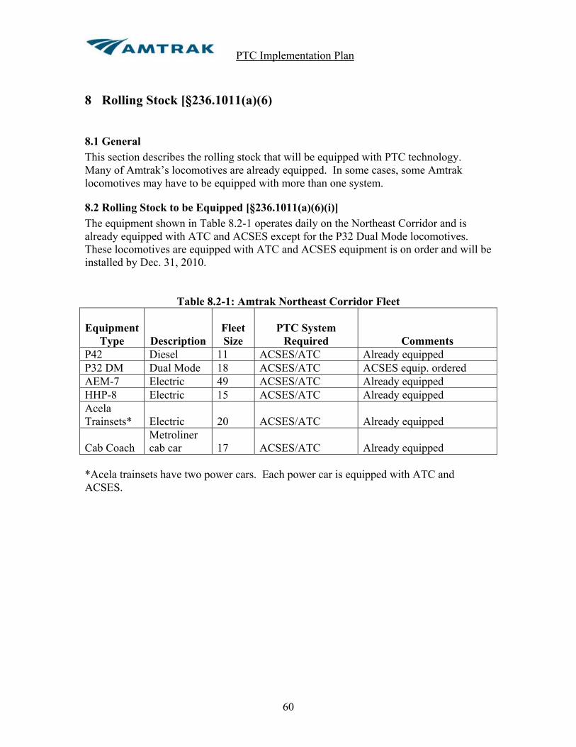
PTC Implementation Plan
60
8 Rolling Stock [§236.1011(a)(6)
8.1 General This section describes the rolling stock that will be equipped with PTC technology. Many of Amtrak’s locomotives are already equipped. In some cases, some Amtrak locomotives may have to be equipped with more than one system.
8.2 Rolling Stock to be Equipped [§236.1011(a)(6)(i)] The equipment shown in Table 8.2-1 operates daily on the Northeast Corridor and is already equipped with ATC and ACSES except for the P32 Dual Mode locomotives. These locomotives are equipped with ATC and ACSES equipment is on order and will be installed by Dec. 31, 2010.
Table 8.2-1: Amtrak Northeast Corridor Fleet
Equipment
Type
Description
Fleet Size
PTC System
Required
Comments P42 Diesel 11 ACSES/ATC Already equipped P32 DM Dual Mode 18 ACSES/ATC ACSES equip. ordered AEM-7 Electric 49 ACSES/ATC Already equipped HHP-8 Electric 15 ACSES/ATC Already equipped Acela Trainsets*
Electric
20
ACSES/ATC
Already equipped
Cab Coach
Metroliner cab car
17
ACSES/ATC
Already equipped
*Acela trainsets have two power cars. Each power car is equipped with ATC and ACSES.

PTC Implementation Plan
61
The equipment shown in Table 8.2-2 is operated outside the Northeast Corridor except for 11 of the P42 locomotives which operate on the NEC and are currently equipped with ATC/ACSES. All of the remaining equipment will receive V-ETMS on-board equipment including the P32 Dual Mode locomotives which will also be ACSES equipped.
Table 8.2-2: Amtrak Fleet Roster to be Equipped with PTC
LVPS ATC Equipment Vehicle
Class Builder Number of Units
Power source
Event Recorder
Brake System
P42 GE 205 Diesel 74 VDC GRS Micro Cab/PHW WABTEC CCB I
P40 GE 29 Diesel 74 VDC GRS Micro Cab/PHW WABTEC 26 L
P32ED GE 15 Diesel 74 VDC None WABTEC 26 L P32ED GE 3 Diesel 74 VDC PHW WABTEC 26 L P32DM GE 18 Diesel 74 VDC PHW WABTEC CCB I Cab Bags Amtrak 21 NPCU 74 VDC None WABTEC 26 L Cab Bags Amtrak 1 NPCU 74 VDC PHW IITS WABTEC 26 L Surf CABS Alstom 9 NPCU 74 VDC PHW IITS WABTEC 26 L Gen Set MPI 2 Diesel 74 VDC None WABTEC 26 L
Table 8.2-3: Numbers by Class Vehicle Class Numbers
P42 1-142, 144-148, 150-207 P40 800-806, 809,811, 813-818, 821-828, 830-832, 835, 837,839 P32ED 500, 503-518 P32DM 700-717 Cab Bags 90200 90208, 90213-90215, 90218-90222, 90224, 90225,90229, 90230, 90250-
90253, 90278,90340 90368, 90413 Surf Cabs 6900-6908 Gen Sets TBD
8.3 Schedule [§236.1011(a)(6)(ii)] All the electric fleet, operating on the NEC, is already equipped with ATC and ACSES. 49 sets of VETMS equipment is on order from Wabtec. The first five sets should be delivered by April 30, 2010. These five sets will be installed on P42 locomotives to be used for test trains on the BNSF between Oklahoma City and Fort Worth. The remaining sets will be installed on equipment used in the Los Angeles basin. Amtrak’s goal is to have all the locomotive fleet used in the Los Angeles basin equipped by December 31, 2012.

PTC Implementation Plan
62
Following is a schedule for equipping the fleet of 292 vehicles:
Year No. of Sets of V-ETMS to be Installed 2010 49 sets 2011 50 sets 2012 50 sets 2013 50 sets 2014 50 sets 2015 43 sets
It should be noted that the dual mode locomotives operated between New York and Albany will have to be equipped with both ACSES to operate on Amtrak and Metro North and V-ETMS to operate on CSX. Also, the fleet of locomotives that operate with ITCS on the Michigan Line will also have to be equipped with V-ETMS to operate in NS territory.
8.4 Tenant Railroads [§236.1011(a)(iii)(A) and (B)]
8.4.1 Tenants Operating on the NEC The following tenant railroads are already equipped with ACSES to operate between New Haven, CT and Boston, MA:
! MBTA ! CSX ! P&W ! Connecticut DOT Commuter trains
The following tenant commuter railroads operating on the Northeast Corridor will equip with ACSES and are filing their own PTC Implementation Plans:
! The Long Island Rail Road ! New Jersey Transit ! Septa
Each of the above railroads will provide a schedule of installation with their PTCIP’s. MARC will equip their electric locomotives with ACSES and their diesel fleet and cab cars with V-ETMS to operate on the NEC between Perryville, MD and Washington, DC. MARC is filing its own PTC Implementation Plan and will provide a schedule of installation in it’s PTCIP.
markgriffith
markgriffith

PTC Implementation Plan
63
Virginia Railway Express (VRE) operates from Virginia to Washington Union Terminal through the First Street Tunnel between CSX’s CP Virginia and Amtrak’s “A” interlocking in WUT. VRE will be required to equip with V-ETMS to operate on CSX and will also operate with V-ETMS on Amtrak. VRE is filing their own PTC Implementation Plan and will provide a schedule of installation in their PTCIP. Norfolk Southern operates on portions of the NEC between New York and Washington with the heaviest amount of traffic between Perryville, MD and Baltimore. NS also operates local freight on the Harrisburg Line between Philadelphia and Harrisburg, PA. NS will operate with V-ETMS in this territory and will provide a schedule of installation with their PTC Implementation Plan. CSX operates on portions of the NEC between New York and Washington and for a short distance on the line between Mill River and Springfield in New England. CSX will operate with V-ETMS in this territory and will provide a schedule of installation with their PTC Implementation Plan. Canadian Pacific Railway has operating rights between Perryville and Landover, MD but seldom operates any freight trains in this territory. CP will operate with V-ETMS if and when they operate on the NEC and will provide a schedule of installation with their PTC Installation Plan. Conrail Shared Assets operates local freight service between Newark, NJ and Philadelphia, PA on the NEC. Conrail will operate with V-ETMS and will provide a schedule of installation in their PTC Installation Plan. Connecticut Southern Railroad operates local freight trains on the Springfield Line between New Haven, CT and Springfield, MA. They plan to equip a few of their locomotives with V-ETMS or ACSES to operate on this segment of the NEC. They have responded to our request for an equipment schedule by letter (Appendix A, p. 19) stating that they will comply with the regulations but are unable to provide specifics as to the number of locomotives that will be equipped or a schedule for installation. Pan Am Railways operates local freight trains on the Springfield Line between New Haven, CT and Springfield, MA. They plan to equip 3 GP-40 locomotives (#’s 360 – 362) with ACSES by July 2012 (see Pan Am letter, Appendix A, p. 45).
8.4.2 Tenants Operating on the Michigan Line Norfolk Southern operates a small fleet of ITCS equipped locomotives on the Michigan Line. Amtrak and NS plan to work with General Electric Transportation Systems to make ITCS equipped locomotives interoperable with V-ETMS territory. The Chicago South Shore and South Bend Railroad operates on a short section of the Michigan Line in the Michigan City, IN area between MP 228.0 and MP 228.79. As explained in Section 5.2.1, Amtrak and Chicago South Shore and South Bend Railroad

PTC Implementation Plan
64
are requesting an exception per §236.1006 (b) (4) (ii) with the additional condition that temporal separation will be maintained between Amtrak passenger trains and CSS&SBRR freight trains. Providing FRA grants this exception, Chicago South Shore and South Bend Railroad freight engines will not be equipped with ITCS on-board systems and will operate within the described territory (MP 228.0 to MP228.79) unequipped with temporal separation.
8.4.3 Tenants Operating in Chicago Union Terminal Metra operates commuter service into Chicago Union Terminal and will equip all of their fleet with V-ETMS on-board equipment. Metra is filing its own PTCIP and will provide a schedule of installation with its plan. Norfolk Southern Railway, Union Pacific Railroad and BNSF Railroad all operate freight trains between CP 21st Street and 16th Street (BNSF Jct.). NS and UP will operate with V-ETMS on-board equipment and BNSF will operate with ETMS. Each of these railroads are filing their own PTC Implementation Plans and will provide a schedule of installation with their plan. Chicago Rail Link operates some freight service between CP 21st Street and 16th Street (BNSF Jct.). Amtrak has requested information about the number of locomotives that will be equipped and a schedule to do so but CRL has not provided this information (see latest e-mail correspondence, Appendix A, p. 15A).
8.4.4 Tenants Operating in New Orleans Union Passenger Terminal Canadian National Railroad operates an occasional local freight train in NOUPT to deliver paper to the Times Picayune. CN will operate with V-ETMS on-board equipment. CN is filing its own PTCIP and will provide a schedule of installation with its plan.

PTC Implementation Plan
65
9 Wayside Devices [§236.1011(a)(7)]
9.1 General This section identifies the wayside devices or subsystems which must be installed for the PTC system. It is broken down by line segment as the systems will be installed. It addresses major components. The unit counts may change as design is finalized by line segment. At this stage of the project these are estimated quantities only. Wayside Interface Units (WIU) or Encoders will be installed at interlockings. It is estimated that one WIU or encoder will be required for every 4 controlled signals. The schedule for installation was addressed in Section 7 and will not be repeated here.
9.2 Northeast Corridor – ACSES Installation Following is a breakdown of the equipment to be installed on the NEC for ACSES by ACSES line segment. Line 3 (Mill River to Cove) already has ACSES installed and in service.
Line Segment Transponders
Encoders or WIU
BCP Radio & Antenna
Line 1 & 7 New York to Zoo 1398 111 26 Line 2 Zoo to Avenue 1550 96 36 Line 4 Philadelphia to Harrisburg 910 51 20 Line 5 Mill River to Springfield 300 22 12 Line 6 JO to Shell 155 27 7 Line 8 Empire Connection 140 4 3
Total 4453 311 104
9.2.1 Northeast Corridor – VETMS Overlay in ACSES Territory The WIU’s at the interlockings will serve as ACSES Encoders and V-ETMS WIU’s so no additional wayside equipment will be required other than V-ETMS base radios which will be installed approximately every 10 miles. A Back Office Server will be installed at the new CETC dispatching center in Wilmington, DE to handle the V-ETMS database, movement authorities and TSR data. V-ETMS base radios and antennas will be installed as follows: Line 1 Hudson to Zoo: 7 locations Line 2 Zoo to Avenue: 12 locations Line 4 Philadelphia to Harrisburg: 10 locations Line 5 Mill River to Springfield: 6 locations
9.3 Michigan Line – ITCS Installation Most of the Michigan Line already has ITCS installed. Amtrak currently has a contract with General Electric Transportation Systems (GETS) to complete the installation of

PTC Implementation Plan
66
ITCS on the line. The following devices will be installed along with new wired houses for most of the signal and crossing locations.
Location Qty. / Type Servers WIU Radio/AntennaControl Points 6 8 Signals & Crossings 61 A fiber optic cable is being installed on the Michigan Line. All the WIUs will be connected to the server locations by the fiber cable. No 220 MHz radios will be required at the WIU locations.
9.4 Chicago Terminal – V-ETMS Chicago Terminal will have V-ETMS installed between Polk Street and 21st Street (CN Crossing) where passenger speed is 30 mph and freight speed is 10 mph. An MTEA is being submitted for the passenger terminal where passenger speed is 15 mph.
Location WIU Radio/Antenna CP Taylor 1 1 CP Roosevelt 2 1 CP 16th Street 1 1 CP Lumber Street 1 1 21st Street (CN Crossing) 1 1 A Back Office Server (BOS) will be installed in the dispatching center at Chicago Union Station and a data radio and leaky coax cable will be installed in the platform area of the station for train initialization and downloading of database information.
9.5 New Orleans Union Passenger Terminal – V-ETMS New Orleans Union Passenger Terminal will have V-ETMS installed on segments previously described where passenger speed is 30 mph. An MTEA is being submitted for the area between the station building to CP Clara and the South Wye where passenger speed is only 10 to 15 mph.
Location WIU Radio/Antenna CP Clara 1 1 CP North Wye Jct. 1 1 CP Carrollton Jct. 1 1 Southport Jct. 1 1 East City Jct. 1 1 A data radio and antenna will be installed in the platform area of the station for train initialization and downloading of database information. The terminal is dispatched from the Chicago dispatching center where the BOS will be located.
markgriffith

PTC Implementation Plan
67
9.6 CP Virginia to “A” Interlocking – Washing Union Terminal – V-EMTS This line segment connects Washington Union Terminal to the CSX mainline leading south. This segment is used by Amtrak and VRE passenger trains.
Location WIU Radio/Antenna CP Virginia 1 1 Signals 18LA and 20LA 1 1 Signals 1339/1349 1 1 “A” Interlocking 1 1 A data radio and antenna will be installed in the lower level platform area of Washington Union Station for train initialization and downloading of database information. The BOS will be located at the CETC dispatching center in Wilmington, DE.
markgriffith

PTC Implementation Plan
68
10 Designating Track as Main Line or Non-Main Line [§236.1011(a)(8)]
10.1 General Amtrak defines main track as a track designated by Timetable upon which train movements are authorized by ABS or interlocking rules. On Amtrak, all main tracks are signaled. Non-signaled tracks are not designated as main tracks and are generally operated at restricted speed. Yards, industrial tracks, Maintenance of Way storage tracks, non-signaled sidings and non-signaled running tracks are not main line track. These tracks are not used by revenue passenger trains. In some cases, yard tracks and yard leads are signaled but are not considered main tracks. For example, Wye Bridge Switching Center in Ivy City Yard in Washington, DC is a non-vital switching center equipped with power operated switches protected by low signals displaying only Restricting. Sunnyside Yard in Queens, New York consists of Loop interlocking on the loop tracks leading from the main tracks in F interlocking to the yard, R switching center and Q interlocking. No revenue passenger trains operate in Sunnyside Yard and all trains operate at restricted speed. All of these tracks are non-main line tracks.
10.2 Main Line Track Appendix C through L contains timetable information and track charts that can be used to determine main line tracks. Appendix C contains track charts and timetable information for the Main Line – New York to Philadelphia (NYP) (Line segments 1&7). The chart in section 240-N1 on Page 165 of the timetable lists all the main line tracks between A Interlocking in New York and Zoo Interlocking in Philadelphia. All non-main line tracks are shaded yellow on the track charts in Appendix C. Appendix D contains track charts and timetable information for Main Line –Philadelphia to Washington (PW) (Line segment 2). The chart in section 240-P1 on Pages 187 and 188 of the timetable lists all the main line tracks between Girard Interlocking and CP Avenue in Washington, DC. All non-main line tracks are shaded yellow on the track charts in Appendix D. Appendix E contains track charts and timetable information for Main Line – Philadelphia to Harrisburg (PH) (Line segment 4). The chart in section 240-G1 on Pages 232 and 233 of the timetable lists all the main line tracks between Zoo Interlocking in Philadelphia and State Interlocking in Harrisburg. The chart in section 240-C1 on Page 245 of the timetable lists the main line tracks on the 36th Street Connection linking Penn Interlocking and 30th Street Station in Philadelphia to the Harrisburg Line. All non-main line tracks are shaded yellow on the track charts in Appendix E.

PTC Implementation Plan
69
Appendix F contains track charts and timetable information for Main Line – Mill River to Springfield (MRS) (Line segment 5). The chart in section 240-M1 on page 133 of the timetable lists the main line tracks. All non-main line tracks are shaded yellow on the track charts in Appendix F. Appendix G contains track charts and timetable information for New York Penn Station to New Rochelle (JO to Shell) (Line segment 6). The chart in section 240-H1 on page 143 of the timetable lists the main line tracks between Harold and CP216 on the Hellgate Line and the chart in section 240-T1 on page 151 of the timetable lists the main line tracks between New York Penn Station and Harold. All non-main line tracks are shaded yellow on the track charts in Appendix G. Appendix H contains track charts and timetable information for the Empire Connection (Line segment 8). The chart in section 240-E1 on page 147 of the timetable lists the main line tracks between A Interlocking and CP12 on Metro North Railroad. All non-main line tracks are shaded yellow on the track charts in Appendix H. Appendix I contains track charts and timetable information for Washington Union Terminal including the track segment between CP Virginia and A Interlocking. All non-main line tracks are shaded yellow on the track charts in Appendix I. Appendix J contains track charts and timetable information for the Michigan Line. All non-main line tracks are shaded yellow on the track charts in Appendix J. Appendix K contains track charts and timetable information for Chicago Union Station. The main tracks are shown as solid black lines on pages 2 and 3 of the timetable. Appendix L contains track charts and timetable information for New Orleans Union Passenger Terminal. All non-main line tracks are shaded yellow on the track chart in Appendix L.
10.5 Non-Main Line Track Yards, industrial tracks, running tracks, storage tracks, repair tracks, etc. are not considered main line tracks. Generally trains operate at restricted speed not exceeding an upper speed limit listed in the timetable for these tracks. In most cases these tracks are not signaled but in some cases they are. These tracks are not generally used by revenue passenger trains. Following is a list of Major Yards on the Northeast Corridor all of which are Non-Main Line tracks:
! Southampton Yard in Boston, MA ! Sunnyside Yard in New York including Loop, R and Q Interlockings ! Penn Coach Yard in Philadelphia ! Ivy City Yard in Washington, DC including Wye Bridge switching station ! Wilmington Shops, Wilmington, DE

PTC Implementation Plan
70
Following is a list of yards and terminals outside the NEC that are not considered main line track:
! 14th Street Yard in Chicago (Chicago Union Terminal) ! Coach Yard in New Orleans Union Passenger Terminal ! Coach yard in Toledo, Ohio (leased by Amtrak) ! Hialeah Yard in Miami, FL ! Sanford Autotrain Facility in Sanford, FL ! Lorton Autotrain Facility in Lorton, VA ! Oakland Yard in Oakland, CA ! 8th Street Yard in Los Angeles, CA ! King Street Yard, Seattle Washington ! Rensselaer Maintenance Facility and Yare in Rensselaer, NY ! Beech Grove Mechanical Facility in Beech Grove, IN ! St. Louis Coach Yard in St. Louis, MO ! Brighton Park Maintenance Facility in Chicago, IL
Many of the above are leased by Amtrak. This list includes the larger facilities. There are numerous other small yards or storage tracks around the country that are not main line track. Main line track would be defined in the timetable by the host railroad that Amtrak operates over that is associated with the facility, yard or storage track. The track charts in Appendix C through M are included as reference for property covered in this PTCIP. Non-main line tracks are identified on these charts by yellow highlighting. Operation on these tracks is at restricted speed and in some cases it is defined as “restricted speed not exceeding XX” where XX is some speed less than 20 mph.

PTC Implementation Plan
71
11 Exceptions to Risk-Based Prioritization [§236.1011(a)(9)] The design of the ACSES expansion on the NEC is already under contract and much of the material is already on order. The ACSES work will be completed for all lines on the NEC before V-ETMS is installed in Chicago even though Chicago Union Terminal ranked higher in priority than Lines 5, 6 and 8 on the NEC. The design of Line 6 (JO to Shell) is scheduled to be completed before Line 4 (Harrisburg Line) which has higher priority. The work force in New York will be able to continue working on Line 6 after the completion of Lines 1&7 (New York to Philadelphia). There is only 4 months difference in the completion dates for Lines 4 and 6. The Michigan Line is third from last in priority but will be completed first, even before completion of any of the NEC ACSES lines. ITCS is already in service on this line and Amtrak has a contract with General Electric Transportation Systems (GETS) to complete the installation of ITCS. The contract is funded with ARRA funds and must be completed by February 2011. ACSES and ITCS are mature PTC systems and therefore can be completed much faster than V-ETMS which is new and unproven. Amtrak will have to work closely with Metra and the Class I railroads in Chicago to implement V-ETMS. Close coordination will also be required with NS and CSX as V-ETMS is developed and implemented on the NEC. For this reason the implementation of V-ETMS will lag behind the completion of ACSES and ITCS.

PTC Implementation Plan
72
12 Alternative Arrangements for Rail-to-Rail At-Grade Crossings [§236.1011(a)(10)]
There are two rail-to-rail at-grade crossings on Amtrak property. Each of them is addressed below.
12.1 At-Grade Crossing in Michigan City, IN Amtrak’s single main track crosses Northern Indiana Commuter Transportation District (NICTD) tracks at CP 10th Street in Michigan City, IN. There are no connecting tracks between the two railroads. The speed on the Amtrak main track is 50 mph. NICTD plans to install V-ETMS on their railroad and will install a WIU on their track to enforce a positive stop at their home signals. Amtrak is installing ITCS and will install an ITCS WIU to enforce a positive stop at the Amtrak home signals.
12.2 At-Grade Crossing at CP 21st Street in Chicago Union Terminal Amtrak’s two main tracks leading into Chicago Union Terminal cross two main tracks belonging to Canadian National Railroad. The speed on the Amtrak main tracks is 15 mph and the speed on the CN tracks is restricted speed not exceeding 10 mph. Amtrak will install V-ETMS between CP 21st Street and Polk Street in the terminal and will enforce a positive stop at the crossing diamonds at CP 21st Street. The CN tracks will not be PTC equipped.

PTC Implementation Plan
73
13 Main Line Track Exclusion Addendum [§236.1019]
13.1 General This section discusses Main Line Track Exclusion Addendums (MTEAs) that are being requested for various areas of Amtrak property. MTEAs on other railroads will be filed in their PTC Implementation Plans. The MTEA requests being filed as part of this plan are in accordance with § 236.1019(b) – Passenger terminal exception. In all cases the MTEA areas are in Passenger terminal or station areas where speeds are 20 mph or less. Each MTEA request is detailed separately in the following sections. Each MTEA submission provides a summary track description and layout as well as a narrative description of the normal train operations. MTEA’s are being requested for each of the following areas: 1. Washington Union Terminal (between the south limits of “A” Interlocking to the north limits of “C” Interlocking including all of “K” interlocking) where speeds are 15 and 20 mph. 2. Penn Station New York (between west limits of “A” Interlocking and east limits of “JO” and “C” Interlocking) where speeds are 15 mph. 3. Boston South Station (between east limits of Cove Interlocking and Tower 1 Interlocking where speeds are 15 mph, between Tower 1 Interlocking and Boston South Station where speeds are 10 mph and between Broad Interlocking and Tower 1 where speeds are 15 mph). 4. Springfield Terminal (between Sweeney Interlocking and Springfield Station where the speed is 10 mph). 5. Harrisburg, PA passenger terminal area (between signals 100L &102L in State Interlocking and the west limits of Harris Interlocking, Amtrak/NS boundary, where speed is 15 mph). 6. Chicago Union Station (between Polk Street and Canal Street where speed is 15 mph). This includes the North and South Passenger terminal areas and the connecting tracks between them. 7. New Orleans Union Passenger Terminal; ((a) between CP Clara Street and NOUPT Station Tracks where speed is 10 mph; (b) between CP Clara Street and South Wye Jct. where speed is 15 mph; (c) between CP South Wye Jct. and Earhart Jct. where speed is 15 mph; (d) between North Wye Jct. and South Wye Jct. where speed is 10 mph).
PTC Implementation Plan
74
13.2 Washington Union Terminal (WUT) An MTEA is requested for Washington Union Terminal between the South limits of “A” Interlocking starting at signals 18L and 20L (Fig. 13.2-3) and the North limits of “C” Interlocking (Fig. 13.2-1) including all of “K” interlocking (Fig. 13.2-2) and all platform tracks within Washington Union Station with the exception of numbers 40, 41 and 42 tracks between CP Avenue and Bridge J (shaded in pink in Fig. 13.2-1). The CSX tracks north of signals 445 and 513 (shaded in blue in Fig. 13.2-1) are not included in this MTEA. The basis for this MTEA request is § 236.1019(b) Passenger terminal exception. The trackage in the terminal area for which the MTEA is being requested is used exclusively by passenger and commuter operations. The maximum track speed within WUT on the tracks included in this request is 15 mph (20 mph northbound between J and H signal bridges and on all tracks except 40 and 42 within the terminal). All trains operating into and out of WUT on Amtrak operated tracks will be equipped with an onboard cab signal system which will enforce restricted speed capped at 20 mph within the terminal. Trains operating from CSX tracks will be equipped with a V-ETMS PTC system and speeds will be capped at 20 mph by that system to the extent which is possible. Interlocking rules are in effect, prohibiting reverse movements (except with signal indications controlled by a dispatcher) for the entire area for which the MTEA is being requested. Freight movements will not be performed within the MTEA area. The speed on tracks 40 and 42 between CP Avenue and Signal Bridge “J” is 45 mph. These tracks are equipped with cab signals and will be PTC equipped. The speed on track 41 is only 15 mph but a positive stop will be enforced at signal 419 for northbound moves. The crossovers between 39 and 40 tracks will provide flanking protection for the 45 mph moves on track number 40. The terminal is a slow speed area with closely spaced signals. It would be extremely difficult, if not impossible, to place transponders the proper distance to enforce a positive stop at stop signals. Likewise, it would be extremely difficult, if not impossible, to enforce a stop signal at the proper point with a system such as V-ETMS that uses GPS for location determination due to the close spacing of signals. There are many switching moves within the terminal for adding and dropping cars and changing engines further complicating the installation of PTC. WUT is used by Amtrak intercity passenger trains and MARC and VRE commuter trains. There are 24 Amtrak trains and 30 VRE trains operating into and out of the terminal through the First Street Tunnel each day. There are 88 Amtrak trains operating between WUT and Philadelphia and 48 MARC trains operating between WUT and Baltimore with another 38 MARC trains operating between WUT and CSX lines. In addition, there are numerous moves to and from Ivy City Yard each day.
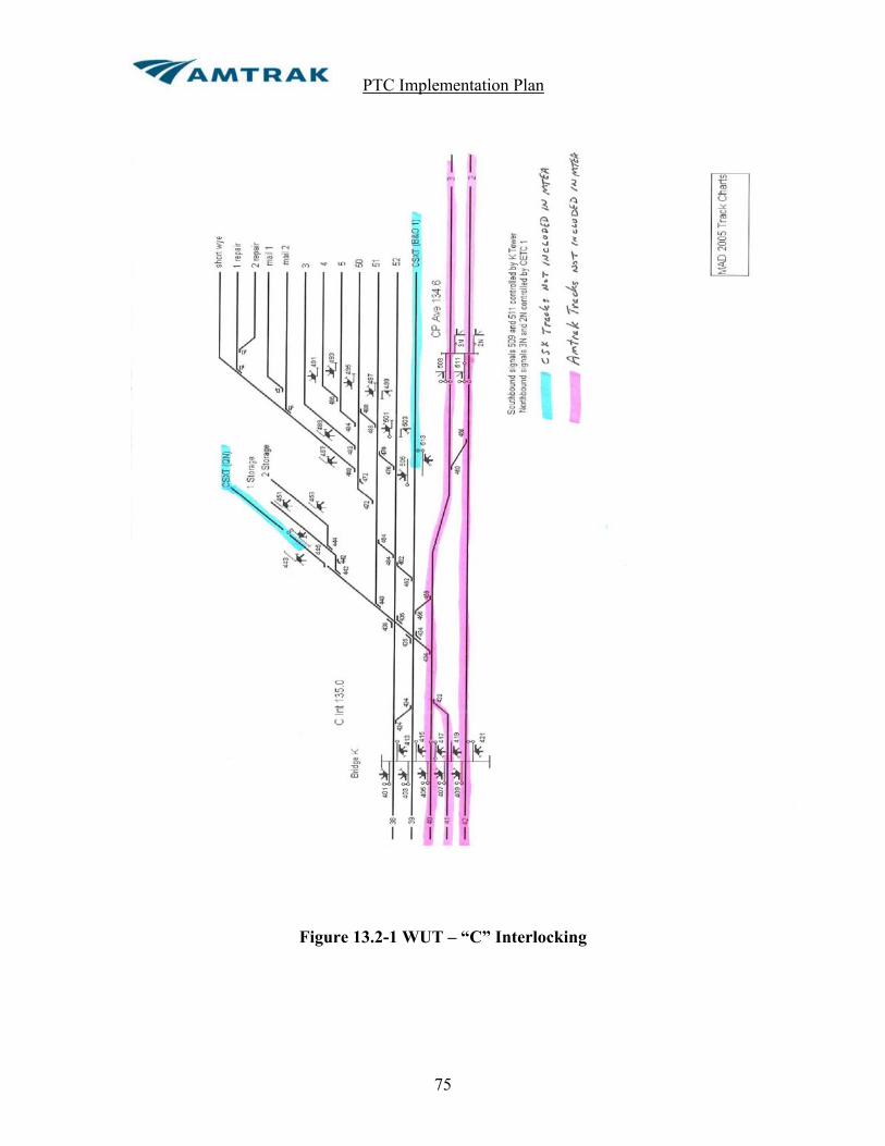
PTC Implementation Plan
75
Figure 13.2-1 WUT – “C” Interlocking

PTC Implementation Plan
76
Figure 13.2-2 WUT – “K” Interlocking

PTC Implementation Plan
77
Figure 13.2-3 WUT – “A” Interlocking

PTC Implementation Plan
78
13.3 Penn Station New York (PSNY) An MTEA is requested in Penn Station New York between the 10th Avenue signal bridge (westbound signal bridge just east of the 10th Avenue Portal) and signal 162E on the Empire Connection and the east limits of “JO” (512W signal on Line 1 and 508W signal on Line 2) and “C” (634W signal on Line 3 and 636W signal on Line 4) interlockings. The tracks in E-Yard and the tracks leading to The Long Island Railroad’s West side storage yard (1,2,3 and 4 Lead tracks) are not considered main line tracks and will also not be PTC equipped. Refer to the track and signal layout drawing Figure 13.3-1 in Appendix M. The basis for this MTEA request is § 236.1019(b) Passenger terminal exception. The trackage in the terminal area for which the MTEA is being requested is used exclusively by passenger and commuter operations. The maximum track speed within PSNY is 15 mph except for 3X and 4X tracks which will be limited to 20 mph. All trains operating into and out of PSNY are equipped with an onboard cab signal system. The onboard cab signal systems will enforce restricted speed (not exceeding 20 mph) within the limits of Penn Station. Interlocking rules are in effect, prohibiting reverse movements (except with signal indications controlled by a dispatcher) for the entire area for which the MTEA is being requested. Freight movements will not be performed within the MTEA area. Penn Station New York is the busiest station on the Amtrak network. There are 114 daily Amtrak trains and 340 New Jersey Transit trains operating to and from the station through the two North River (Hudson River) tunnels and 24 Amtrak trains operating to and from the station through the Empire tunnel. There are 42 daily revenue Amtrak trains and 455 Long Island Rail Road revenue trains operating to and from the station through the four East River tunnels. Additionally there are 197 non-revenue Amtrak and NJT trains operating through the East River tunnels to and from Sunnyside yard and 108 non-revenue LIRR trains operating to and from the Long Island Rail Road. Due to the close spacing of signals and switches in this complex terminal it would be extremely difficult if not impossible to install PTC to enforce a positive stop at stop signals. All trains operate at slow speed (15 mph) and there are many switching moves that are made throughout the day.

PTC Implementation Plan
79
13.4 Boston South Station An MTEA is requested in the Boston South Station terminal area between the “end of track” in South Station (including all of Tower 1 interlocking) to the east limits of Cove interlocking on the NEC main tracks and to Broad interlocking on the Dorchester Branch. Refer to the track and signal layout drawing in Figures 13.4-1 and 13.4-2 in Appendix M. This property is owned by MBTA but is leased to and operated and dispatched by Amtrak. The basis for this MTEA request is § 236.1019(b) Passenger terminal exception. The trackage in the terminal area for which the MTEA is being requested is used exclusively by passenger and commuter operations. The maximum track speed within this area is 15 mph (10 mph within South Station platform areas). All trains operating into and out of South Station are equipped with an onboard cab signal system. The onboard cab signal systems will enforce restricted speed (not exceeding 20 mph) within the limits the MTEA area. Interlocking rules are in effect, prohibiting reverse movements (except with signal indications controlled by a dispatcher) for the entire area for which the MTEA is being requested. Freight movements will not be performed within the MTEA area. There are 38 daily Amtrak trains operating to and from South Station. MBTA operates 112 trains into the station from the Northeast Corridor through Cove interlocking and 102 trains per day from their commuter lines through Broad interlocking. There are also yard moves to and from Southampton Yard. All trains are operated at slow speed (15 mph max.).
PTC Implementation Plan
80
13.5 Springfield Passenger Terminal An MTEA is being requested in Springfield, MA for the area between the South limits of Sweeney interlocking to and including the station tracks (tracks 4, 6 and 8) in Springfield Station. Refer to track and signal layout chart in Figure 13.5-1 on the following page. The basis for this MTEA request is § 236.1019(b) Passenger terminal exception. The trackage in the terminal area for which the MTEA is being requested is used exclusively by passenger and commuter operations. The maximum track speed within this area is 10 mph. All trains operating into and out of Springfield Station are equipped with an onboard cab signal system. The onboard cab signal system will enforce restricted speed (not exceeding 20 mph) within the limits the MTEA area. Interlocking rules will be in effect, prohibiting reverse movements (except with signal indications controlled by a dispatcher) for the entire area for which the MTEA is being requested. Freight movements will not be performed between Sweeney and Springfield station on No.2 track. Amtrak operates 12 daily trains between New Haven, CT and Springfield, MA. These trains terminate at Springfield Station and then make the reverse run to New Haven. There are no other carriers operating into Springfield Station on these tracks.

PTC Implementation Plan
81
Figure 13.5-1 Springfield Passenger Terminal

PTC Implementation Plan
82
13.6 Harrisburg, PA Passenger Terminal An MTEA is being requested for the Harrisburg, PA passenger terminal area between signals 100L & 102L and the west limits of Harris interlocking (boundary between Amtrak and NS). Refer to the track and signal layout drawing in Figure 13.6-1 on the following page. The basis for this MTEA request is § 236.1019(b) Passenger terminal exception. The trackage in the terminal area for which the MTEA is being requested is used exclusively by passenger trains. The maximum track speed within this area is 15 mph. All trains operating into and out the terminal are equipped with an onboard cab signal system. The onboard cab signal system will enforce restricted speed (not exceeding 20 mph) within the limits the MTEA area. Interlocking rules will be in effect, prohibiting reverse movements (except with signal indications controlled by a dispatcher) for the entire area for which the MTEA is being requested. Freight movements will not be performed within the MTEA area. Amtrak operates 28 trains per day to and from the Harrisburg terminal not including switching moves for turning trains, changing engines etc. All moves are made at slow speed (15 mph) and there is seldom more than 2 trains moving at one time.

PTC Implementation Plan
83
Figure 13.6-1

PTC Implementation Plan
84
13.7 Chicago Union Terminal An MTEA is being requested for the portion of the Chicago Union Terminal between the Polk Street Overhead Bridge South of Chicago Union Station to Canal Street (junction with Metra) at the Northern end of the Terminal. Refer to the track and signal layout drawings in Figures 13.7 – 1 to 13.7 –4 in Appendix K. The basis for this MTEA request is § 236.1019(b) Passenger terminal exception. The trackage in the terminal area for which the MTEA is being requested is used exclusively by passenger trains. The maximum track speed within this area is 15 mph. All trains operating into and out the terminal will be equipped with an onboard V-ETMS system. The V-ETMS system will enforce the 15 mph speed restriction to the maximum extent possible within the limits the MTEA area. Interlocking rules will be in effect, prohibiting reverse movements (except with signal indications controlled by a dispatcher) for the entire area for which the MTEA is being requested. Freight movements will not be performed within the MTEA area. There are 58 daily Amtrak trains operating to and from Chicago Union Station not including yard moves. There are 151 Metra commuter trains operating between CP Canal and the North side of the station and 134 Metra trains operating to and from the South side of the station.

PTC Implementation Plan
85
13.8 New Orleans Union Passenger Terminal (NOUPT) An MTEA is being requested for the following portions of NOUPT:
! Between CP Clara Street and the Passenger Station including all platform tracks.
! Between CP Clara Street and Earhart Jtc.
! Between CP South Wye Jct. and CP North Wye Jct. Refer to the track and signal layout drawing in Figure 13.8-1 in Appendix M. The basis for this MTEA request is § 236.1019(b) Passenger terminal exception. The trackage in the terminal area for which the MTEA is being requested is used exclusively by passenger trains. The maximum track speed within this area is 15 mph (10 mph between North Wye Jct. and South Wye Jct.). All trains operating into and out the terminal will be equipped with an onboard V-ETMS system. The V-ETMS system will enforce the 15 mph speed restriction to the maximum extent possible within the limits the MTEA area. Interlocking rules will be in effect, prohibiting reverse movements (except with signal indications controlled by a dispatcher) for the entire area for which the MTEA is being requested. Freight movements will not be permitted within the MTEA area where revenue passenger trains are operated. There are four daily, and two tri-weekly, trains operating to and from NOUPT. The Crescent operates daily (one train each direction) between New York and New Orleans through the East City Jct. connection between NOUPT and the Norfolk Southern Railway. The City of New Orleans operates daily (one train each direction) between Chicago and New Orleans through the Southport Jct. connection with the Canadian National Railroad (formerly Illinois Central). The Sunset Limited operates between Los Angeles and New Orleans with arrivals in New Orleans on Tuesdays, Fridays and Sundays and departures on Mondays, Wednesdays and Fridays. The Sunset Limited operates through the Southport Jct. connection with CN. If trains operate on schedule, there is never more than one revenue train moving at a time. There is an occasional freight delivery to the Times Picayune by a CN local freight. These deliveries are scheduled when no revenue passenger trains are operating in the terminal.

PTC Implementation Plan
86
14.0 Appendices The following appendices are included as attachments to this document:
14.1 Appendix A – Agreements and Letters between Amtrak and its Tenant Railroads
14.2 Appendix B – Agreements and Letters between Amtrak and its Host Railroads
14.3 Appendix C – Track Charts and Timetable Information for NEC Line 1 and 7 - New York to Philadelphia
14.4 Appendix D – Track Charts and Timetable Information for NEC Line 2 – Philadelphia to Washington
14.5 Appendix E – Track Charts and Timetable Information for NEC Line 4 – Philadelphia to Harrisburg
14.6 Appendix F – Track Charts and Timetable Information for NEC Line 5 – Mill River to Springfield
14.7 Appendix G – Track Charts and Timetable Information for NEC Line 6 – JO to Shell
14.8 Appendix H – Track Charts and Timetable Information for NEC Line 8 – Empire Connection
14.9 Appendix I – Track Charts and Timetable Information for CP Virginia to Washington Union Terminal
14.10 Appendix J – Track Charts and Timetable Information for Michigan Line
14.11 Appendix K – Track Charts and Timetable Information for Chicago Union Station
14.12 Appendix L – Track Charts and Timetable Information for New Orleans Union Passenger Terminal
14.13 Appendix M – Track Charts in Support of MTEA Requests (Section 13)
14.14 Appendix N – Risk Analysis