National Magnetics Group | TCI · PDF file•raw material production >capabilities...
32
National Magnetics Group | TCI Ceramics ferrites | magnets | garnets | dielectrics
Transcript of National Magnetics Group | TCI · PDF file•raw material production >capabilities...

National Magnetics Group | TCI Ceramicsferrites | magnets | garnets | dielectrics

0011001010001001000100001001000100101100011001000101010010100001001010010010100010010100010
>table of contents
>01 . . . .company profile
>02 . . . .capabilities
>04 . . . .ferrites
>19 . . . .powdered iron and microwave absorbers
>20 . . . .magnets
>22 . . . .microwave ferrites and garnets
>24 . . . .dielectrics
>25 . . . .dielectric resonators
>26 . . . .advanced materials
>27 . . . .engineering notes>29 . . . .ordering
Material Characteristics . . . . . . . . . . . . . . . . . . . . .05Toroids (0.052 to 9.5 inches diameter) . . . . . . . . . .06Squaroids . . . . . . . . . . . . . . . . . . . . . . . . . . . . . . . .07Balun and Multi-hole Cores . . . . . . . . . . . . . . . . . .08Slugs and Threaded Cores . . . . . . . . . . . . . . . . . .09Rods, Slotted Rods, Tubes and Strips . . . . . . . . . .10Beads (EMI) and Sleeves (thin wall) . . . . . . . . . . .12
Beads (EMI): Split and Other . . . . . . . . . . . . . . . . .14Coil Forms . . . . . . . . . . . . . . . . . . . . . . . . . . . . . . .15Plates and Tiles . . . . . . . . . . . . . . . . . . . . . . . . . . .16Blocks and Rounds . . . . . . . . . . . . . . . . . . . . . . . .17Substrates . . . . . . . . . . . . . . . . . . . . . . . . . . . . . . .18Custom Shapes . . . . . . . . . . . . . . . . . . . . . . . . . . .18
Material Characteristics . . . . . . . . . . . . . . . . . . . . .17 Shapes . . . . . . . . . . . . . . . . . . . . . . . . . . . . . . . . . .17
Material Characteristics . . . . . . . . . . . . . . . . . . . . .18 Shapes . . . . . . . . . . . . . . . . . . . . . . . . . . . . . . . . . .18
Material Characteristics: Class Ferrite Spinels . . . 20 Shapes . . . . . . . . . . . . . . . . . . . . . . . . . . . . . . . . . . 21
Material Characteristics . . . . . . . . . . . . . . . . . . . . . 22 Shapes . . . . . . . . . . . . . . . . . . . . . . . . . . . . . . . . . . 22
Material Characteristics . . . . . . . . . . . . . . . . . . . . . 23 Shapes . . . . . . . . . . . . . . . . . . . . . . . . . . . . . . . . . . 23
Powders . . . . . . . . . . . . . . . . . . . . . . . . . . . . . . . . . 28Ignots . . . . . . . . . . . . . . . . . . . . . . . . . . . . . . . . . . . 28
Applications . . . . . . . . . . . . . . . . . . . . . . . . . . . . . . 28Specialty Ceramics. . . . . . . . . . . . . . . . . . . . . . . . . 28
Raw Material Production . . . . . . . . . . . . . . . . . . . . 02Tooling . . . . . . . . . . . . . . . . . . . . . . . . . . . . . . . . . . 02Forming . . . . . . . . . . . . . . . . . . . . . . . . . . . . . . . . . 02Sintering . . . . . . . . . . . . . . . . . . . . . . . . . . . . . . . . . 02
Secondary Operations . . . . . . . . . . . . . . . . . . . . . . 03Inspection . . . . . . . . . . . . . . . . . . . . . . . . . . . . . . . . 03R&D . . . . . . . . . . . . . . . . . . . . . . . . . . . . . . . . . . . . 03
Manufacturing Facilities1210 Win Drive | Bethlehem, Pennsylvania 18017 | USA18450 Showalter Road | Hagerstown, Maryland 21742 | USA
Corporate Headquarters1210 Win Drive | Bethlehem, Pennsylvania 18017-7061 | USA
T 610.867.7600 | F 610.867.0200

00110010100010010001000010010001001011000110001000101010010100001001010010010100010010100010
>company profile
Industry: Manufacturer of technical ceramics (magnetic andadvanced materials) and powdered iron cores
Products/Applications: Ferrites/Powdered Iron: short andmedium wave antennas, filters, differential/common mode andoutput chokes, high frequency noise suppression/shielding(EMI/RFI), inductors, small signal transformers (ie. broadband,matching, pulse and isolation), magnetic power circuits, highfrequency welding, rotary transformers, accelerator cores, pulseshapers, thin film substrates and recording heads.
Magnets: sensing (ie. reed switch activators), holding (ie. 'chip'collectors), torque coupling, electron beam deflection, microwavebiasing, and d.c. motor fields.
Microwave Absorbers: waveguide insert loads and terminatingelements, attenuators, RF shields
Custom Powders: radar absorption, multi-layer chip inductors
Industries Served: Telecommunications, CATV, Automotive,Aerospace, Computer, Medical, Consumer Electronics, Scientific(ie. National Labs) and General Industry
Strategy: Superior customer service through serving nicheindustry applications with comprehensive manufacturingcapabilities and technical know-how, supporting small scale tolarge volume production.
Strengths: Dedication to serving customer requirements, quickdelivery of high volume production, broad range of materials,shapes and sizes, and fabricating techniques, in-house tooling.
Quality: Our quality system adheres to the guidelines of ISO/TS16949:2002 and is geared to provide continuous improvementtowards defect prevention, variation reduction and customersatisfaction. We expect to be ISO9001:2000 (with TS16949compliance) certified in the first quarter of 2006.
Subsidiary: TCI Ceramics, Inc.
Facility: Bethlehem, PA (~ 45,000 Square Feet) (~ 1:30 hoursfrom New York City, NY and Philadelphia,PA)
Employees: ~ 65
Ownership: Private (family)
Founded: 1940 (current ownership: 1977)
Industry: Manufacturer of technical ceramics (magnetic andadvanced materials)
Products/Applications: Garnets and Ferrites(MW): circulatorand isolator elements, phase shifters, thin film substrates
Dielectrics: typically used in conjunction with ferritecomponents in circulator and isolator elements and phaseshifters. Also, used for thin and thick film circuit applications andhigh Q capacitor applications.
Dielectric Resonators: used in oscillator and filter/combinerapplications where miniaturization, temperature stability and lowloss are required. Resonator supports are also supplied.
Hexagonal Ferrites: millimeter wave isolators
Advanced Materials: custom powders for abrasion resistantand thermal barrier coatings (TBC) for gas-turbine (aircraft andpower generation) engines utilizing electron-beam physicalvapor deposition (EB-PVD), solid oxide fuel cells utilizing thermalspraying, low temperature co-fired materials (LTCC)
Industries Served: Telecommunications (wireless handsets andbase stations), Satellite TV, Global Positioning Systems,Defense/Aerospace, Automotive and Custom R&D
Strategy: Superior customer service through serving ourcustomer base with quality products on-time and at a competitiveprice, backed by significant industry experience and researchand development capabilities.
Strengths: High volume production capability, quick delivery,technical support, research and development capability.
Quality: Our quality system adheres to the guidelines of ISO-9000 and is geared to provide continuous improvement towardsdefect prevention, variation reduction and customer satisfaction.We expect to be ISO9001:2000 (with TS16949 compliance)certified in the first quarter of 2006.
Facilities (HQ & Mfg.): Bethlehem, PA (~ 5,000 Square Feet) (~2:15 hours from Hagerstown, MD) (Mfg.): Hagerstown, MD (~ 46,000 Square Feet) (~ 1:15 hoursfrom Washington, DC and Baltimore, MD)
Employees: ~ 25
Ownership: National Magnetics Group, Inc.
Founded: 1972 (current ownership 2001)
>national magnetics group
>tci ceramics
company profile
www.magneticsgroup.com

•raw material production
>capabilities
•toolingComplete in-house capability using high speed tool steel and sintered carbide
Blending/Mixing/Screening/ClassifyingParticle Size Reduction: ball mill/attritor mill/jet mill/jaw crusherCalcining: rotary/batch/tunnel kilnDrying: oven/spray/granulation
00110010100010010001000010010001001011000110002000101010010100001001010010010100010010100010
•formingMechanical Pressing: (up to 250 tons); qty.: 51
– utilized for high volume productionExtrusion: (up to 1 in. diameter and 12 in. length); qty.: 3
– utilized for shapes requiring lengths greater than 2 in.Cold Isostatic Pressing (CIP): (up to 6 in. diameter
and 20 in. length); qty.: 7– utilized when, due to the size or complexity of the
shape or due to time and/or volume– considerations, conventional mechanical pressing
is not feasibleMolding:
– utilized for non-ceramic materials
•sinteringGas & Electric Atmosphere Controlled Tunnel Kilns: up to
1400C/2552F; qty.: 8Electric Atmosphere Controlled Batch Kilns: up to 1700C/3092F);
qty.:52

www.magneticsgroup.com
>capabilities
capabilities•secondary operationsGrinding (sintered:hard and green:soft): flat-th/od/id/form/drilling/millingSlicing: from 0.005 thick and 6 in. diameterLapping: finish 0.2 – 0.4 µmPolishing: finish 0.1 –0.2 µm (std.)Optically Polished: finish 0.075 – 0.1 µm (less than 50 angstroms)Hot Isostatic Pressing (HIP): up to 1500 C and up to 30,000 psi
– utilized for ferrite in magnetic heads in contact with tape, which require a dense – material, virtually without pores and resistant to abrasion. also, due to near – theoretical densities achieved, magnetic properties of most materials are – significantly improved
Magnetizing: axial, radial and multi-pole up to 10,000 oerstedsAutomatic & Manual Electrical Sorting/Grading: up to 10,000 parts/hourAnnealing: magnetic and thermalTumbling: edge rounding (prevents sharp edges
from cutting wire insulation)Marking: color coding/identificationCoating: silicone/parylene/epoxyMetallization: silverWinding, LeadsTape & Reel
•inspection• Complete magnetics testing lab (including x-ray spectroscopy) • Complete dimensional (including Zygo interferometry)
•r&d• Material development and characterization • Affiliation with Lehigh University’s Material Research Center• Affiliation with University of Pennsylvania, Department of Materials
Science and Engineering• Affiliation with National Institute of Standards (NIST), Ceramics Division
00110010100010010001000010010001001011000110003000101010010100001001010010010100010010100010

00110010100010010001000010010001001011000110004000101010010100001001010010010100010010100010
>ferrites
ferrites: material characteristics
www.magneticsgroup.com
00110010100010010001000010010001001011000110005000101010010100001001010010010100010010100010
>ferritesmaterial characteristics
Type: NiZn
M5 7.5 1750 <3500[100MHz] 320 107 0.1-400 filter, transformer toroid, rod, balunM4 12 1800 <850[10MHz] 500 109 0.1-400 filter, transformer toroid, rod, balunM3 20 2500 <500[100MHz] 500 107 0.1-400 antenna, filter, toroid,
transformer rod, balunM2 40 2300 <150[50MHz] 450 107 0.1-50 antenna, filter, toroid,
transformer rod, balunM 125 2400 <40[2.5MHz] 350 107 0.1-25 antenna, filter, toroid, rod,
transformer plate,strip>200 emi suppression bead, rod
N 250 3000 <100[2.5MHz] 250 108 0.1-4 filter, transformer bead, toroid, rodG3 300 3750 <100[2.5 MHz] 250 108 0.1-10 filter, transformer toroid, rod, balunG2 370 3200 <65[0.1MHz] 200 106 0.1-5 filter, transformer toroid, rod, balunG4 400 4600 <35[0.1MHz] 230 108 0.1-10 antenna, block,
particle accelerator custom, rodG 500 2500 <100[1MHz] 200 103 0.1-1 antenna, plate
filter, transformerH1 700 3200 <15[0.05MHz] 190 107 0.05-1 antenna, rod
< 80[1MHz] filter, transformerCN20 800 3800 <100[1MHz] 170 106 0.5-30 particle accelerator block, customH 850 2950 <250[1MHz] 135 105 20-250 emi suppression bead, rodH2 850 3200 <250[1MHz] 155 107 0.05-10 antenna, toroid
filter, transformerN16 1600 3000 <250[1MHz] 110 107 1-100 emi suppression toroid, balunCMD5005 1600 3200 <250[1MHz] 130 108 1-100 particle accelerator block, customCMD908 2200 3300 130 108 recording head block, customN23 2300 1200 <350[1MHz] 95 108 30-1,500 emi suppression plate
Type: MnZn
R 450 1600 <100[2.5MHz] 90 108 10-500 filter, transformer rodP 600 2800 <25[0.2MHz] 150 102 0.05-3 antenna, rod,
filter, transformer tube, stripM08 850 4600 <6[0.1MHz] 240 260 0.5-1.5 power conversion toroidM20 2000 4900 <15[0.1MHz] 190 102 .05-0.2 antenna, slug,
filter, transformer rod, toroid0.05-30 emi suppression bead
M24 2300 4700 <13[0.1MHz] 190 102 0.1-0.5 power conversion block, customM25 2500 4700 <5[0.1MHz] 210 103 0.1-0.5 welding (impeder), rod,
antenna tube, stripM29 2900 4700 <5[0.1MHz] 185 103 0.5-2 power conversion block, customMND5200 3200 5100 180 400 recording head block, customMND5100 5000 5000 180 20 recording head block, customM50 5000 4500 <15[0.1MHz] 170 50 0.1 filter, transformer toroid, balunMN60 6500 4500 <12[0.1MHz] 165 200 0.1-0.3 filter, transformer block, customM100 10000 4200 <10[0.03MHz] 135 20 0.1 filter, transformer block, custom
Type: Non-Magnetic
NMD1 1 na na -70 108 recording head block, custom
Property Initial Saturation Loss Factor Curie Volume Advised Application CommonPermeability Flux Density [@frequency] Temp. Resistivity Frequency Areas Shape
Unit gauss 10-6 ˚C Ω-cm MHzSymbol µi Bsat tanδδ/µi Tc ρρ f
Notes:1. valves are typical and based on measurements of a standard toroid at 25˚C.2. detailed information (i.e. material data sheets, physical and thermal properties, reference material and definition of terms) available at www.magneticsgroup.com
00110010100010010001000010010001001011000110006000101010010100001001010010010100010010100010
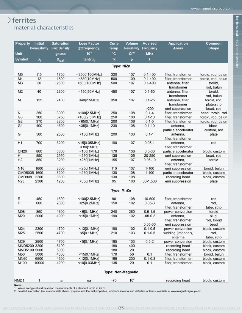
>ferritestoroids (0.052” to 9.5” dia.)applications: antennas, power supplies, pulse and wide band transformers, emi suppression
T-1038 0.052 1.32 0.032 0.81 0.040 1.02 0.004 127.4 0.32 0.003 0.0008T-1341 0.062 1.57 0.027 0.69 0.027 0.69 0.005 110.2 0.32 0.003 0.0009T-1048 0.080 2.03 0.035 0.89 0.055 1.40 0.018 54.4 0.41 0.008 0.0031T-1131 0.080 2.03 0.050 1.27 0.050 1.27 0.012 105.3 0.50 0.005 0.0024T-1143 0.100 2.54 0.050 1.27 0.050 1.27 0.023 71.4 0.55 0.008 0.0043T-1410 0.105 2.67 0.070 1.78 0.050 1.27 0.019 122.0 0.68 0.006 0.0038T-1020 0.120 3.05 0.070 1.78 0.060 1.52 0.04 76.5 0.72 0.009 0.0068T-1028 0.135 3.43 0.040 1.02 0.050 1.27 0.05 40.7 0.55 0.014 0.0075T-980 0.138 3.51 0.051 1.30 0.050 1.27 0.05 49.7 0.64 0.013 0.0083T-1032-2 0.138 3.51 0.070 1.78 0.050 1.27 0.04 72.9 0.77 0.011 0.0081T-1010 0.155 3.94 0.088 2.24 0.050 1.27 0.05 87.4 0.92 0.011 0.0097T-1056 0.175 4.45 0.077 1.96 0.050 1.27 0.08 60.3 0.90 0.015 0.013T-985-1 0.200 5.08 0.100 2.54 0.050 1.27 0.09 71.4 1.11 0.015 0.017T-434 0.230 5.84 0.120 3.05 0.120 3.05 0.29 31.7 1.30 0.041 0.054T-1057 0.237 6.02 0.070 1.78 0.120 3.05 0.38 16.9 0.97 0.057 0.055T-1146 0.241 6.12 0.112 2.84 0.120 3.05 0.34 26.9 1.28 0.048 0.061T-1023 0.250 6.35 0.131 3.33 0.187 4.75 0.5 20.5 1.42 0.069 0.098T-1012 0.300 7.62 0.120 3.05 0.187 4.75 0.9 14.4 1.46 0.101 0.148T-131-1 0.310 7.87 0.180 4.57 0.187 4.75 0.7 24.3 1.86 0.077 0.142T-994 0.375 9.53 0.187 4.75 0.125 3.18 0.8 28.4 2.07 0.073 0.15T-999 0.495 12.57 0.168 4.27 0.250 6.35 3.4 9.2 2.19 0.239 0.53T-975 0.495 12.57 0.224 5.69 0.250 6.35 3.0 12.5 2.59 0.207 0.54T-560 0.495 12.57 0.277 7.04 0.250 6.35 2.6 17.0 2.91 0.171 0.50T-318 0.500 12.70 0.295 7.49 0.250 6.35 2.5 18.8 3.03 0.162 0.49T-998 0.500 12.70 0.312 7.92 0.250 6.35 2.4 21.0 3.12 0.149 0.46T-962 0.595 15.11 0.258 6.55 0.250 6.35 4.5 11.8 3.04 0.256 0.78T-1063 0.625 15.88 0.291 7.39 0.250 6.35 4.8 12.9 3.32 0.257 0.85T-1096 0.632 16.05 0.325 8.26 0.250 6.35 4.6 14.9 3.55 0.239 0.85T-964 0.700 17.78 0.390 9.91 0.250 6.35 5.3 16.9 4.11 0.243 1.00T-1441 0.755 19.18 0.419 10.64 0.250 6.35 6.1 16.8 4.42 0.263 1.16T-663 0.870 22.10 0.540 13.72 0.250 6.35 7.3 20.7 5.4 0.261 1.41T-1015-1 1.000 25.40 0.500 12.70 0.250 6.35 12.0 14.3 5.5 0.39 2.14T-961 1.170 29.72 0.760 19.30 0.250 6.35 12.0 22.9 7.5 0.326 2.43T-665 1.250 31.75 0.750 19.05 0.375 9.53 23.0 12.9 7.6 0.59 4.5T-1100 1.395 35.43 0.641 16.28 0.375 9.53 36.0 8.5 7.4 0.87 6.4T-1442 1.490 37.85 1.087 27.61 0.375 9.53 24.0 20.9 10.1 0.48 4.9T-1086 1.550 39.37 0.965 24.51 0.375 9.53 34.0 13.9 9.7 0.69 6.7T-1090 1.785 45.34 0.770 19.56 0.375 9.53 61.0 7.8 9.1 1.16 10.5T-682 1.855 47.12 0.450 11.43 0.375 9.53 76.0 4.7 6.7 1.44 9.7T-989 2.400 60.96 1.400 35.56 0.500 12.70 118.0 9.2 14.5 1.57 22.8T-987 3.100 78.74 1.865 47.37 0.500 12.70 191.0 9.7 19.0 1.95 37.0T-1337 3.320 84.33 1.725 43.82 0.500 12.70 251.0 7.6 18.8 2.48 46.6T-1043 3.400 86.36 1.760 44.70 0.500 12.70 264.0 7.5 19.2 2.55 48.9T-995 3.500 88.90 2.000 50.80 0.500 12.70 257.0 8.8 20.8 2.36 49.1T-1443 4.300 109.22 2.785 70.74 0.500 12.70 335.0 11.4 27.4 2.41 65.9T-1113 4.320 109.73 1.875 47.63 0.500 12.70 472.0 5.9 22.1 3.72 82.1T-1044 4.420 112.27 2.490 63.25 0.500 12.70 416.0 8.6 26.1 3.03 79.1T-1054 5.475 139.07 3.975 100.97 0.500 12.70 442.0 15.5 37.1 2.40 88.9T-1009 5.725 145.42 2.440 61.98 1.000 25.40 1672.0 2.9 28.9 9.98 288.7T-1112 6.260 159.00 1.995 50.67 1.000 25.40 2195.0 2.2 26.7 12.35 330.0T-1006 6.260 159.00 3.875 98.43 1.000 25.40 1507.0 5.2 38.9 7.55 293.8T-1182 6.260 159.00 4.545 115.44 1.000 25.40 1155.0 7.7 42.4 5.49 232.5T-1078 9.500 241.30 7.000 177.80 1.000 25.40 2572.0 8.1 64.8 8.00 518.7
Effective Effective EffectiveCore Path Cross Core
Outside Diameter Inside Diameter Thickness Mass Constant Length Sectional Area Volumep/n in mm in mm in mm grams (∑⁄/A) cm-1 (/e) cm (Ae) cm2 (Ve) cm3

ferrites: toroids/squaroidswww.magneticsgroup.com
00110010100010010001000010010001001011000110007000101010010100001001010010010100010010100010
>ferritessquaroidsapplications: antennas, power supplies, pulse and wide band transformers, emi suppression
S-1149 0.079 2.01 0.036 0.91 0.060 1.52 0.025 52.5 0.4 0.01 0.003S-1301 0.236 5.99 0.118 3.00 0.445 11.30 1.6 8.0 1.3 0.16 0.2S-1445 0.250 6.35 0.083 2.11 0.125 3.18 0.6 17.9 1.1 0.06 0.1S-1390 0.354 8.99 0.156 3.96 0.125 3.18 1.1 24.2 1.8 0.08 0.1S-1391 0.354 8.99 0.187 4.75 0.125 3.18 1.0 31.0 2.0 0.07 0.1S-1186 0.394 10.01 0.197 5.00 0.531 13.49 5.3 6.7 2.2 0.32 0.7S-1446 0.505 12.83 0.134 3.40 0.125 3.18 2.4 14.9 1.9 0.13 0.2S-1160 1.000 25.40 0.400 10.16 0.500 12.70 35.0 5.4 4.9 0.90 4.4S-1360 1.265 32.13 0.465 11.81 0.500 12.70 57.0 4.9 5.9 1.19 7.0S-1161 1.400 35.56 0.600 15.24 0.600 15.24 80 4.9 7.1 1.46 10.4
Effective Effective EffectiveCore Path Cross Core
Outside Diameter Inside Diameter Thickness Mass Constant Length Sectional Area Volumep/n in mm in mm in mm grams (∑⁄/A) cm-1 (/e) cm (Ae) cm2 (Ve) cm3
Notes:1. material designation will be a prefix for NiZn materials (ie.M-1010) or a suffix for MnZn materials (ie. T-1010-M50)2. magnetic (inductance) tolerance +/-20% (for ui 7.5 - 5,000) and +/-30% (for ui> 5,000) note: automated grading/sorting of toroids (od < 0.375) for tighter inductance tolerances available3. mechanical tolerances approximately +/-1.5% (nominal values may vary per material)4. thickness adjustable to suit application requirements (given existing tool limitations)5. call if required sizes not found (not all tool sizes are listed), also see Beads6. parts available coated with parylene (0.0005 in. nominal) or epoxy (>0.001 in.)
(ie. T-1010P-M50 or M-995E)7. parts available slotted

00110010100010010001000010010001001011000110008000101010010100001001010010010100010010100010
>ferritesbalun and multi-hole coresapplications: emi suppressors, chokes, wideband, pulse and power transformers, inductors
BC-1121 1 0.057 1.45 0.105 2.67 0.050 1.27 0.020 0.51BC-1098-1 1 0.080 2.03 0.135 3.43 0.058 1.47 0.036 0.91BC-1098 1 0.080 2.03 0.135 3.43 0.095 2.41 0.036 0.91BC-1602 1 0.120 3.05 0.245 6.22 0.125 3.18 0.055 1.40BC-814 1 0.160 4.06 0.275 6.99 0.125 3.18 0.073 1.85BC-497 1 0.285 7.24 0.525 13.34 0.260 6.60 0.150 3.81
BC-788 2 0.250 6.35 0.250 6.35 0.050 1.27BC-1404-4 2 0.284 7.21 0.250 6.35 0.052 1.32BC-1133 2 0.450 11.43 0.500 12.70 0.100 2.54
BC-1195 3 0.067 1.70 0.213 5.41 0.080 2.03 0.062 x 0.036 1.6 x 0.9BC-1183 3 0.290 7.37 1.465 37.21 0.750 19.05 0.460 x 0.090 11.7 x 2.3BC-1151 4 0.108 2.74 0.220 5.59 0.040 1.02 0.050 1.27BC-970 5 0.236 5.99 0.394 10.01 0.032 0.81
Thickness (a) Width (b) Length Inner Diameter (d)p/n figure in mm in mm in mm in mm
Notes:1. material designation will be a prefix for NiZn materials (ie.M-1098) or a suffix for MnZn materials (ie. BC-1098-M50)2a.magnetic (inductance) tolerance +/-25% (for ui 7.5 - 5,000) and +/-30% (for ui> 5,000)2b.magnetic (impedance) tolerance +/-20%3. mechanical tolerances approximately +/-1.5% (nominal values may vary per material)4. length adjustable to suit application requirements (given existing tool limitations)5. call if required sizes not found (not all tool sizes are listed)6. parts available coated with parylene (0.0005 in. nominal) (ie. BC-1098P-M50)
a
bd
d
a
a
bd
a
d
a
b
d
Figure 1
Figure 4
Figure 2
Figure 5
Figure 3

ferrites: baluns and multi-hole cores/slugs and threaded cores
www.magneticsgroup.com
>ferritesslugs and threaded coresapplications: rfid (transponders), power, emi suppression, antennas/filters, chokes, ignition coils, pulse transformers
SC-1334 0.016 0.41 0.030 0.76 0.0005SC-1312 0.018 0.46 0.030 0.76 0.001SC-1518 0.022 0.56 0.250 6.35 0.008SC-1326 0.024 0.61 0.030 0.76 0.001SC-1093 0.032 0.81 0.187 4.75 0.01SC-1127 0.040 1.02 0.187 4.75 0.02SC-1153 0.055 1.40 0.187 4.75 0.04SC-555 0.065 1.65 0.375 9.53 0.1SC-1139 0.090 2.29 0.187 4.75 0.1SC-1349 0.095 2.41 0.700 17.78 0.4SC-1083 0.116 2.95 0.312 7.92 0.3SC-1103 0.125 3.18 0.312 7.92 0.3SC-1107 0.150 3.81 1.250 31.75 1.8SC-246 0.156 3.96 0.500 12.70 0.8SC-1047 0.187 4.75 0.875 22.23 1.9SC-1075 0.195 4.95 1.250 31.75 3.0SC-919 0.250 6.35 2.000 50.80 7.8SC-1074 0.300 7.62 1.000 25.40 5.6SC-1061 0.312 7.92 2.000 50.80 12.0SC-1071 0.330 8.38 2.000 50.80 14.0SC-971 0.375 9.53 2.000 50.80 18.0SC-111 0.485 12.32 2.000 50.80 29.0SC-999 0.500 12.70 2.000 50.80 31.0SC-1434 0.670 17.02 0.625 15.88 17.0SC-1516 0.845 21.46 1.000 25.40 45.0SC-1435 0.900 22.86 2.000 50.80 101.0SC-1045 0.975 24.77 2.000 50.80 119.0SC-1436-1 1.062 26.97 0.750 19.05 53.0SC-1471 1.280 32.51 1.500 38.10 153.0SC-1437 1.350 34.29 0.750 19.05 85.0SC-1155 1.425 36.20 0.750 19.05 95.0SC-1438 1.670 42.42 0.250 6.35 43.0SC-1439 2.070 52.58 1.000 25.40 267.0SC-1440 3.100 78.74 0.500 12.70 300.0
Outside Diameter Length Massp/n in mm in mm grams
Notes:1. material designation will be a prefix for NiZn materials (ie.M-919) or a suffix for MnZn materials (ie. SC-919-M20)2. magnetic tolerance for inductance +/-10% and for Q -20%3. mechanical tolerances approximately +/-1.5% (nominal values may vary per material)4. outer diameter may be ground to tighter tolerances (ie.+/- 0.001 in.)5. length adjustable to suit application requirements (given existing tool limitations)6. for lengths > 2.000 in., see Rods / Tubes & Impeders / Strips7. refer to Effective Permeability of Ferrite Rods for relationship between material permeability and slug (effective) permeability8. call if required sizes not found (not all tool sizes are listed)9. parts available coated with parylene (0.0005 in. nominal) (ie. SC-11334P-M20)10. call for threaded core sizes11. parts available threaded (28 or 32 pitch)
00110010100010010001000010010001001011000110009000101010010100001001010010010100010010100010

00110010100010010001000010010001001011000110010000101010010100001001010010010100010010100010
>ferritesrods, slotted rods, tubes and stripsapplications: rfid (transponders), pagers, rf antennas for portable receivers and/or transmitters, impeders for hf welding, ignitioncoils, pulse transformers
TX-218 0.218 5.5 0.063 1.6 7.500 191.0 20TX-236 0.236 6.0 0.118 3.0 7.874 200.0 21TX-276 0.276 7.0 0.118 3.0 7.874 200.0 31TX-315 0.315 8.0 0.157 4.0 7.874 200.0 37TX-375 0.375 9.5 0.125 3.2 7.500 191.0 58TX-394 0.394 10.0 0.197 5.0 7.874 200.0 57TX-472 0.472 12.0 0.197 5.0 7.874 200.0 90TX-500 0.485 12.3 0.125 3.2 7.500 191.0 103TX-551 0.551 14.0 0.276 7.0 7.874 200.0 112TX-625 0.625 15.9 0.150 3.8 7.500 191.0 172TX-625 0.630 16.0 0.315 8.0 7.874A 200.0 146TX-750 0.750 19.1 0.150 3.8 7.500 191.0 252TX-750 0.748 19.0 0.354 9.0 7.874A 200.0 213TX-827 0.827 21.0 0.394 10.0 7.874 200.0 260TX-875 0.875 22.2 0.150 3.8 7.500A 191.0 347TX-875 0.875 22.2 0.431 10.9 7.874 200.0 285TX-1000 1.000 25.4 0.150 3.8 7.500 191.0 457
Outside Diameter Inside Diameter Length Massp/n in mm in mm in mm grams
RX-125 0.125 3.18 1.500 38.0 1RX-250 0.250 6.35 7.500 191.0 29RX-312 0.312 7.92 7.500 191.0 46RX-375 0.375 9.53 7.500 191.0 66RX-500 0.485 12.32 7.500 191.0 110RX-625 0.625 15.88 7.500 191.0 183RX-875 0.875 22.3 7.500 191.0 358RX-1000 1.000 25.40 7.500 191.0 468
Outside Diameter Length Number of Massp/n in mm in mm Slots grams
RX-236 0.236 5.99 7.874S 200.0 6 14RX-315 0.315 8.00 7.874S 200.0 6 35RX-394 0.394 10.01 7.874S 200.0 6 63RX-472 0.472 11.99 7.874S 200.0 8 91RX-551 0.551 14.00 7.874S 200.0 8 131RX-630 0.630 16.00 7.874S 200.0 8 177RX-748 0.748 19.00 7.874S 200.0 8 257
Outside Diameter Length Number of Massp/n in mm in mm Slots grams
•rods
•slotted rods (impeders)
•tubes
Notes:1. suffix S designates slotted (approx. 0.040 x 0.090 in. deep)
Notes:1. suffix A designates different inner diameter from standard and tubes may be supplied slotted

ferrites: rods, slotted rods, tubes and stripswww.magneticsgroup.com
>ferritesrods, slotted rods, tubes and stripsapplications: rfid (transponders), pagers, rf antennas for portable receivers and/or transmitters, impeders for hf welding, ignitioncoils, pulse transformers
SX-095 0.095 2.4 0.095 2.4 3.000 76.2 2SX-155 0.155 3.9 0.074 1.9 3.000 76.2 3SX-240 0.240 6.1 0.180 4.6 3.000 76.2 10SX-350 0.350 8.9 0.200 5.1 4.000 101.6 22SX-390 0.390 9.9 0.091 2.3 4.000 101.6 11SX-370 0.370 9.4 0.100 2.5 4.000 101.6 12SX-480 0.480 12.2 0.120 3.0 4.000 101.6 18SX-500 0.500 12.7 0.125 3.2 4.000 101.6 20SX-625 0.625 15.9 0.140 3.6 7.500 190.5 52SX-625 0.625 15.9 0.250 6.4 7.500A 190.5 93SX-675 0.675 17.1 0.120 3.0 7.500 190.5 48SX-725 0.725 18.4 0.120 3.0 7.500 190.5 52SX-750 0.750 19.1 0.245 6.2 7.500 190.5 109SX-780 0.780 19.8 0.165 4.2 7.500 190.5 77SX-875 0.875 22.2 0.180 4.6 7.500 190.5 94SX-1000 1.000 25.4 0.375 9.5 7.500 190.5 223SX-1250 1.250 31.8 0.250 6.4 7.500 190.5 186
Outside Diameter Inside Diameter Length Massp/n in mm in mm in mm grams
•strips
Notes:1. most edges have full radius; suffix A designates different thickness from standard2. material designation will be a prefix for NiZn materials (ie.RMX-500-7500) or a suffix for MnZn materials (ie. SX-500-4000-M20)3. magnetic tolerance for inductance +/-10% and for Q -20% (grading available for tighter tolerances)4. mechanical tolerances approximately +/-5% (cross sectional), +/-2% (length) (nominal values may vary per material) and straightness (or camber) is 0.011 in. per inch of length(0.050 max.)5. parts are custom cut to length, insert length desired in p/n (ie. RMX-500-2500) to suit application requirements6. outer diameter may be ground to tighter tolerances (ie.+/- 0.002 in.), add suffix F (ie. RPX-375-3000F)7. refer to Effective Permeability of Ferrite Rods for relationship between material permeability and rod (effective) permeability8. call if required sizes not found (not all tool sizes are listed)9. silicone treatment (moisture proofing) available upon request,
add suffix S (ie. RMX-1000-8000S)
00110010100010010001000010010001001011000110011000101010010100001001010010010100010010100010

00110010100010010001000010010001001011000110012000101010010100001001010010010100010010100010
>ferritesbeads (EMI) and sleeves (thin wall)applications: emi suppression
SB-1447 0.064 1.63 0.022 0.56 0.125 3.18 0.03 11 49 75SB-819 0.179 4.55 0.022 0.56 0.130 3.30 0.3 23 100 154SB-905 0.081 2.06 0.023 0.58 0.125 3.18 0.05 13 58 89SB-1026 0.075 1.91 0.028 0.71 0.125 3.18 0.04 10 45 69SB-1018 0.138 3.51 0.031 0.79 0.118 3.00 0.1 15 65 99SB-1048 0.075 1.91 0.034 0.86 0.055 1.40 0.02 4 16 25SB-1082 0.138 3.51 0.037 0.94 0.150 3.81 0.2 17 73 111SB-1527 0.076 1.93 0.043 1.09 0.320 8.13 0.1 15 67 103SB-1027 0.102 2.59 0.043 1.09 0.100 2.54 0.1 7 32 49SB-1117 0.150 3.81 0.043 1.09 0.250 6.35 0.3 26 115 176SB-1496 0.076 1.93 0.043 1.09 0.320 8.13 0.1 15 67 103SB-1031 0.112 2.84 0.047 1.19 0.085 2.16 0.1 6 27 42SB-980 0.138 3.51 0.047 1.19 0.118 3.00 0.1 11 47 72SB-1118 0.162 4.11 0.062 1.57 0.250 6.35 0.3 20 88 135SB-968 0.200 5.08 0.062 1.57 0.437 11.10 1.0 43 188 289SB-1032 0.140 3.56 0.070 1.78 0.234 5.94 0.2 14 60 91SB-872 0.158 4.01 0.082 2.08 0.500 12.70 0.6 27 121 185SB-1528 0.161 4.09 0.089 2.26 0.257 6.53 0.3 13 56 86SB-985 0.195 4.95 0.090 2.29 0.250 6.35 0.5 16 71 109SB-965 0.296 7.52 0.094 2.39 0.297 7.54 1.5 29 125 192SB-1142 0.187 4.75 0.102 2.59 0.250 6.35 0.4 13 56 85SB-1309 0.187 4.75 0.105 2.67 0.250 6.35 0.4 12 53 81SB-1077 0.240 6.10 0.105 2.67 0.900 22.86 2.6 62 274 420SB-909 0.144 3.66 0.108 2.74 0.250 6.35 0.1 6 26 41SB-434 0.230 5.84 0.120 3.05 0.060 1.52 0.1 3 14 22SB-1448 0.253 6.43 0.121 3.07 1.100 27.94 3.4 68 299 458SB-1450 0.450 11.43 0.122 3.10 1.100 27.94 13.0 120 529 810SB-1012 0.295 7.49 0.125 3.18 0.187 4.75 0.8 13 59 91SB-1023 0.250 6.35 0.131 3.33 0.500 12.70 1.4 27 119 182SB-1319 0.286 7.26 0.138 3.51 1.000 25.40 3.9 61 268 411SB-1449 0.180 4.57 0.142 3.61 1.100 27.94 0.8 22 96 147SB-131 0.318 8.08 0.167 4.24 1.000 25.40 4.6 54 237 363SB-994 0.375 9.53 0.187 4.75 0.250 6.35 1.6 15 64 98SB-960 0.370 9.40 0.195 4.95 0.190 4.83 1.2 10 45 69SB-1311 0.375 9.53 0.218 5.54 0.280 7.11 1.6 13 56 86SB-1451 0.522 13.26 0.222 5.64 1.100 27.94 15.0 79 346 530SB-1305 0.400 10.16 0.228 5.79 0.300 7.62 2.0 14 62 95SB-967 0.370 9.40 0.242 6.15 0.300 7.62 1.5 11 47 72SB-962 0.560 14.22 0.245 6.22 1.125 28.58 18.0 78 342 525SB-560 0.466 11.84 0.263 6.68 0.500 12.70 4.6 24 105 161SB-1063 0.595 15.11 0.276 7.01 1.100 27.94 19.0 71 311 477SB-998 0.485 12.32 0.312 7.92 0.250 6.35 2.1 9 41 62SB-1453 0.812 20.62 0.342 8.69 1.125 28.58 38.0 81 358 549SB-964 0.670 17.02 0.370 9.40 1.125 28.58 22.0 56 246 377SB-1452 0.705 17.91 0.397 10.08 1.125 28.58 24.0 54 238 364SB-1001 0.705 17.91 0.415 10.54 1.125 28.58 23.0 50 219 336SB-1300 0.731 18.57 0.428 10.87 1.650 41.91 36.0 74 325 498SB-1015 1.010 25.65 0.510 12.95 1.125 28.58 53.0 64 283 434SB-663 0.870 22.10 0.540 13.72 0.250 6.35 7.3 10 44 67SB-1454 1.062 26.97 0.692 17.58 1.000 25.40 40.0 36 158 242SB-665 1.250 31.75 0.750 19.05 0.375 9.53 23.0 16 71 108SB-1455 1.882 47.80 1.221 31.01 1.125 28.58 144.0 41 179 275SB-989 2.276 57.81 1.335 33.91 0.500 12.70 106.0 22 98 150SB-1456 2.125 53.98 1.385 35.18 1.500 38.10 243.0 54 236 362
Impedance (ohms)Outside Diameter Inside Diameter Thickness Mass M20 H M
p/n in mm in mm in mm grams 10MHz 100MHz 250MHz

ferrites: beads (EMI) and sleeves (thin w
all)www.magneticsgroup.com
00110010100010010001000010010001001011000110013000101010010100001001010010010100010010100010
Notes:1. material designation will be a prefix for NiZn materials (ie.H-665) or a suffix for MnZn materials (ie. SB-962-M20)2. impedance values are calculated and are for reference only (actual values vary per application)3. magnetic (impedance: ohms/single turn) tolerance +/-20%4. mechanical tolerances approximately +/-1.5% (nominal values may vary per material)5. length adjustable to suit application requirements (given existing tool limitations)6. call if required sizes not found (not all tool sizes are listed), also see Toroids7. parts available coated with parylene (0.0005 in. nominal) (ie. H-1026P)

00110010100010010001000010010001001011000110014000101010010100001001010010010100010010100010
>ferritessplit and other beads (EMI)applications: emi suppression
SB-1064S 1 0.550 13.97 0.214 5.44 1.105 28.07 0.275 6.99 87 384 588SB-1172 1 0.642 16.31 0.321 8.15 0.625 15.88 0.321 8.15 36 159 244SB-1175 1 0.984 24.99 0.590 14.99 0.462 11.73 0.492 12.50 20 87 133SB-1167 2 0.325 8.26 0.125 3.18 0.600 15.24 0.158 4.01 48 211 323SB-1011S 2 0.620 15.75 0.260 6.60 1.050 26.67 0.295 7.49 76 336 515SB-1016S 2 1.020 25.91 0.314 7.98 1.125 28.58 0.510 12.95 111 488 748SB-1094S 3 0.750 19.05 0.400 10.16 0.300 7.62 0.220 5.59 0.045 1.14 18 79 122SB-1039S 3 1.500 38.10 1.050 26.67 1.000 25.40 0.270 6.86 0.065 1.65 36 159 244SB-1017S 3 2.375 60.33 1.720 43.69 1.050 26.67 0.250 6.35 0.030 0.76 29 127 194SB-1002 4 0.785 19.94 0.515 13.08 1.100 27.94 0.415 10.54 0.145 3.68 45 197 302SB-1085 4 1.080 27.43 0.835 21.21 0.270 6.86 0.300 7.62 0.050 1.27 8 36 55SB-1156 4 1.755 44.58 1.355 34.42 1.125 28.58 0.490 12.45 0.060 1.52 36 159 244
Outer Inner Inner Dimension Impedance (ohms)Dimension (a) Dimension (b) Length Height (d) Height (e) M20 H M
p/n figure in mm in mm in mm in mm in mm 10MHz 100MHz 250MHz
Notes:1. material designation will be a prefix for NiZn materials (ie.H-1064S) or a suffix for MnZn materials (ie. SB-1064S-M20)2. impedance values are calculated and are for reference only (actual values vary per application)3. magnetic (impedance: ohms/single turn) tolerance +/-20%4. mechanical tolerances approximately +/-1.5% (nominal values may vary per material)5. length adjustable to suit application requirements (given existing tool limitations)6. call if required sizes not found (not all tool sizes are listed), also see Balun/Multi-hole Cores
a
d
b
Figure 1a
d
b
Figure 2
ad e
b
Figure 3a
d e
b
Figure 4

www.magneticsgroup.com
>ferritescoil formsapplications: inductors (axial-leaded) capable of handling current from a few milli-amperes to several amperes, determined by thediameter of the wound wire
CF-1210 0.052 1.32 0.150 3.81 0.031 0.79 thru hole 0.03CF-1200 0.058 1.47 0.187 4.75 0.030 0.75 0.070 1.78 0.04CF-1213 0.061 1.55 0.200 5.08 0.030 0.75 0.070 1.78 0.05CF-1204 0.064 1.63 0.200 5.08 0.030 0.75 0.070 1.78 0.05CF-1211 0.070 1.78 0.250 6.35 0.031 0.79 0.083 2.11 0.08CF-1208 0.076 1.93 0.322 8.18 0.038 0.97 0.092 2.34 0.12CF-1209 0.090 2.29 0.275 6.99 0.038 0.97 0.092 2.34 0.14CF-1203 0.103 2.62 0.275 6.99 0.038 0.97 0.092 2.34 0.2CF-1202 0.110 2.79 0.315 8.00 0.038 0.97 0.092 2.34 0.2CF-1201 0.133 3.38 0.348 8.84 0.040 1.02 0.092 2.34 0.4CF-1214 0.140 3.56 0.625 15.88 0.061 1.55 0.092 2.34 0.8CF-1212 0.155 3.94 0.800 20.32 0.062 1.57 0.092 2.34 1.2CF-1207 0.162 4.11 0.500 12.70 0.062 1.57 0.145 3.68 0.8CF-1206-2 0.198 5.03 0.750 19.05 0.062 1.57 0.145 3.68 1.8CF-1215 0.208 5.28 0.750 19.05 0.060 1.52 0.145 3.68 2.0CF-1205 0.250 6.35 0.750 19.05 0.063 1.60 0.145 3.68 2.9
Blind Hole (x2)Outside Diameter Length Diameter Depth Mass
p/n in mm in mm in mm in mm grams
ferrites: split and other beads (EMI)/coil form
s
Notes:1. material designation will be a prefix for NiZn materials (ie.M-1205) or a suffix for MnZn materials (ie. CF-1205-M20)2. magnetic tolerance for inductance +/-10% and for Q -20%3. mechanical tolerances approximately +/-1.5% (nominal values may vary per material)4. outer diameter may be ground to tighter tolerances (ie.+/- 0.001 in.)5. ends may be supplied with V-notches to aid in wire termination6. length adjustable to suit application requirements (given existing tool limitations)7. call if required sizes not found (not all tool sizes are listed)8. parts may be supplied with leads
00110010100010010001000010010001001011000110015000101010010100001001010010010100010010100010

00110010100010010001000010010001001011000110016000101010010100001001010010010100010010100010
>ferritesplates and tilesapplications: emi suppression, rf & adf antennas for portable receivers and/or transmitters
B-1444 0.220 5.59 0.220 5.59 0.220 5.59 1B-1368 0.500 12.70 0.500 12.70 0.250 6.35 5B-1369 0.875 22.23 0.875 22.23 0.250 6.35 15B-1370 1.055 26.80 1.055 26.80 0.250 6.35 22B-1109-1 1.384 35.15 0.541 13.74 0.125 3.18 7B-1331 1.975 50.17 1.975 50.17 0.250 6.35 77B-1371 2.100 53.34 2.100 53.34 0.250 6.35 88B-1070 2.165 54.99 1.375 34.93 0.187 4.75 44B-1430 2.475 62.87 2.475 62.87 0.250 6.35 122B-1049-1 3.500 88.90 3.500 88.90 0.250 6.35 243B-1329 3.572 90.73 2.565 65.15 0.118 3.00 86B-1377 3.870 98.30 3.870 98.30 0.118 3.00 140B-1411 3.937 100.00 3.937 100.00 0.248 6.30 305B-996 4.500 114.30 4.500 114.30 0.250 6.35 402B-1051 5.500 139.70 5.500 139.70 0.500 12.70 1,201B-1053-1 5.500 139.70 2.750 69.85 0.500 12.70 600B-801302 8.000 203.20 1.375 34.93 0.250 6.35 218B-801402 8.000 203.20 1.425 36.20 0.250 6.35 226B-909002 9.000 228.60 9.000 228.60 0.200 5.08 1,286B-1052-2 13.000 330.20 2.125 53.98 0.250 6.35 548
Length Width Thickness Massp/n in mm in mm in mm grams
Notes:1a. material designation will be a prefix for NiZn materials (ie.M-1444) or a suffix for MnZn materials (ie. B-1444-M20)1b. for blocks/rounds/substrates material designation is suffix (ie. B-801212-CMD5005)2a. for plates mechanical tolerances approximately +/-1.5% (nominal values may vary per material)2b. for blocks and rounds mech. tolerance +/-0.020 in., tighter tolerances available upon request3. thickness/length adjustable to suit application requirements (given existing tool limitations)4. blocks and rounds are isostatically pressed and can be supplied 'as fired'5. substrates are available as thin as 0.010 in. with requested surface finish (standard/lapped/polished)6. call if required sizes not found (not all tool sizes are listed)

00110010100010010001000010010001001011000110017000101010010100001001010010010100010010100010
>ferritesblocks and roundsapplications:
B-601004 6.000 152.40 0.950 24.13 0.400 10.16 181B-601010 6.000 152.40 1.000 25.40 1.000 25.40 476B-801106 8.000 203.20 1.100 27.94 0.550 13.97 384B-801212 8.000 203.20 1.250 31.75 1.250 31.75 992B-801515 8.000 203.20 1.500 38.10 1.500 38.10 1,429B-601717 6.000 152.40 1.700 43.18 1.700 43.18 1,376B-801807 8.000 203.20 1.800 45.72 0.750 19.05 857B-602110 6.000 152.40 2.100 53.34 0.950 24.13 950B-202002 2.000 50.80 2.000 50.80 0.250 6.35 79B-212180 8.000 203.20 2.100 53.34 2.100 53.34 2,800B-404002 4.000 101.60 4.000 101.60 0.250 6.35 318B-104610 10.000 254.00 4.600 116.84 1.000 25.40 3,651B-104810 10.000 254.00 4.800 121.92 1.000 25.40 3,810B-505002 5.000 127.00 5.000 127.00 0.250 6.35 496
Length Width Thickness Massp/n in mm in mm in mm grams
•blocks
•rounds
ferrites: plates and tiles/blocks and roundswww.magneticsgroup.com
R-1080 1.000 25.40 8.000 203.20 499R-1280 1.250 31.75 8.000 203.20 779R-1380 1.312 33.32 8.000 203.20 859
Outside Diameter Length Massp/n in mm in mm grams

XXXXXXXXXXXXXXXXXXXXXXXXXXXXXXXXXXXXXXXXXXXXXXXX
Length Width Thickness Massp/n in mm in mm in mm grams
Notes:1a. material designation will be a prefix for NiZn materials (ie.M-1444) or a suffix for MnZn materials (ie. B-1444-M20)1b. for blocks/rounds/substrates material designation is suffix (ie. B-801212-CMD5005)2a. for plates mechanical tolerances approximately +/-1.5% (nominal values may vary per material)2b. for blocks and rounds mech. tolerance +/-0.020 in., tighter tolerances available upon request3. thickness/length adjustable to suit application requirements (given existing tool limitations)4. blocks and rounds are isostatically pressed and can be supplied 'as fired'5. substrates are available as thin as 0.010 in. with requested surface finish
(standard/lapped/polished)6. call if required sizes not found (not all tool sizes are listed)
00110010100010010001000010010001001011000110018000101010010100001001010010010100010010100010
•rounds
R-30.15 3.000 76.20 0.157 3.99 88R-35.15 3.500 88.90 0.157 3.99 120R-45.15 4.500 114.30 0.157 3.99 198R-50.15 5.000 127.00 0.157 3.99 245
Outside Diameter Thickness Massp/n in mm in mm grams
•square/rectangle
>ferritessubstratesapplications: XXX
>custom shapesFor your custom part or application requirement, call our engineering department with desired dimensions or to check availabilityfrom our stock tooled shapes.
need new part numbers

www.magneticsgroup.com
00110010100010010001000010010001001011000110019000101010010100001001010010010100010010100010
>powdered iron and microwave absorbersmaterial characteristicsapplications: loads, terminations, attenuators
>shapes• Toroids• Slugs and Threaded
Cores
• Baluns• Plates• Custom
3120 8.5 35 1 - 3 5.0 10 - 200 carbonyl iron, higher Q at hi freq. (vs. CTM3118), high cost3118 9.0 30 2 - 4 5.0 1 - 60 carbonyl iron, higher Q at hi freq. (vs. CTM3976), high cost3976 10.0 95 3 - 5 5.0 0.1 - 40 carbonyl iron, high Q, most widely used, moderate cost3900 20.0 280 7 - 9 6.5 0.05 - 10 reduced carbonyl iron, high Q, < 1 MHz, high permeability, high cost3908 35.0 255 5 - 7 6.5 0.05 - 2 reduced carbonyl iron, medium Q, high permeability, high cost3866 60.0 950 11 - 13 6.1 0.06- 50 annealed sponge iron, high permeability, low Q, low cost
Property Initial Temp. Stability Particle Density AdvisedPermeability (-55 to +125˚C) Size Frequency
Unit ui ppm/C µm g/cc MHz FeaturesSymbol D f
ferrites: substrates/custom shapes | pow
dered iron and microw
ave absorbers

00110010100010010001000010010001001011000110020000101010010100001001010010010100010010100010
>magnetsmaterial characteristicsapplications: XXX
•ceramic: ferriteprocessing: ceramic, dry(isotropic)/wet(anisotropic) uniaxial pressing and high temperature air sinteringfeatures: high operating temperature, corrosion resistant, low electrical and thermal conductivity, low cost
C1* 2300 1860 3250 1.05 4.8 450 250 10C1S* 2360 1930 3300 1.2 4.8 450 250 10C5 3800 2400 2500 3.4 4.8 450 250 10C7 3400 3230 4000 2.75 4.8 450 250 10C8A 3850 2950 3050 3.5 4.8 450 250 10C8B 4200 2913 2960 4.12 4.8 450 250 10C9 3800 3516 4010 3.32 4.8 450 250 10C10 4000 3617 3510 3.82 4.8 450 250 10C11 4300 2512 2560 4.32 4.8 450 250 10* = isotropic (dry pressed)
•bonded: ferriteprocessing: injection molding, extrusion or rollingfeatures: complex shapes, precise mechanical tolerances
R05 1500 1150 2000 0.5 3.7 450 120 10R07 1750 1300 1950 0.7 3.7 450 120 10R09 2050 1500 2400 0.9 3.7 450 120 10R11 2250 1825 2400 1.1 3.7 450 120 10R13 2350 2000 2800 1.3 3.8 450 120 10R14 2450 2100 2850 1.4 3.8 450 120 10
•rare earth: neodymium iron boron (sintered)processing: powder metallurgy, dry(anisotropic) isostatic or uniaxial pressing with vacuum sinteringfeatures: high magnetic flux density, high magnetic and thermal stability, low operating temperature, reactive(coating required)
N33 11500 10500 12000 32.0 7.4 310 80 30N35 11900 10900 12000 34.5 7.4 310 80 30N38 12300 11300 12000 37.5 7.4 310 80 30N40 12650 11600 12000 39.5 7.4 310 80 30N42 13000 11600 12000 41.5 7.4 310 80 30N45 13500 11000 12000 44.5 7.4 310 80 30
•rare earth: neodymium iron boron (bonded)processing: injection molding or die pressing (isotropic) and thermal curefeatures: high strength; complex shapes (injection molding); reactive(coating required)
N3.5 4000 3400 8300 3.5 4.2 360 100 35N5.0 5100 3950 7500 5.0 5.0 360 100 35N7.0 6000 4400 7500 7.0 5.7 360 100 35N8.0 6300 5300 15000 8.0 5.9 305 120 45N9.5 6800 5700 10500 9.5 6.1 470 120 35
AdvisedProperty Residual Flux Coercive Intrinsic Max. Energy Density Curie Max. Operating Magnetizing
Density Force Coercive Force Product Temperature Temperature FieldUnit gauss oersted oersted MGOe g/m3 ˚C ˚C kOeSymbol Br HCM HCJ BHmax D Tc

magnets: m
aterial characteristicswww.magneticsgroup.com
>magnetsmaterial characteristics
•rare earth: samarium cobaltprocessing: powder metallurgy, dry(anisotropic) isostatic or uniaxial pressing with vacuum sinteringfeatures: high strength; reactive(coating required), high temperature stability
S18 8750 8000 17000 17.0 7.4 750 250 35S20 9400 8600 17000 20.0 7.4 750 250 35S24 9800 9450 17000 23.0 7.4 750 250 35S24G* 9850 8700 21500 23.0 7.4 800 300 40S26G* 10350 9700 21500 25.0 7.4 800 300 40S28G* 10650 9750 20500 27.0 7.4 800 300 40S30G* 10900 10150 13500 29.0 7.4 800 300 30* = 2:17 grade vs. 1:5 grade
•metal: alnicoprocessing: powder metallurgy process utilizing controlled hydrogen atmosphere high temperature sinteringfeatures: fine crystalline metallic structure; highest temp. stability; corrosion resistant; high mechanical strength
A11* 6800 380 1.13 6.9 810 450 1.5A12* 6000 500 1.2 6.9 810 450 2.0A15* 7200 500 1.55 7.0 810 450 2.0A16* 7000 600 1.6 7.0 810 450 2.5A46R** 12000 600 4.65 7.3 860 525 2.5A50R** 12500 600 5 7.3 860 525 2.5A55R** 12500 650 5.5 7.3 860 525 2.5A65R** 13000 700 6.5 7.3 860 525 2.5A75R** 13500 740 7.5 7.3 860 525 2.7A35R** 10000 720 3.5 7.3 860 525 2.7A45C*** 7000 1750 4.5 7.3 860 525 6.3A22C*** 5860 1250 2.2 7.3 860 550 4.6A40C*** 8000 1250 4 7.3 860 550 4.6A50C*** 8000 1380 5 7.3 860 550 4.8A75C*** 9000 1380 7.5 7.3 860 550 4.8A90C*** 10500 1400 9 7.3 860 550 5.2* = isotropic; ** = anisotropic: high remanance; *** = anisotropic: high coercivity
AdvisedProperty Residual Flux Coercive Intrinsic Max. Energy Density Curie Max. Operating Magnetizing
Density Force Coercive Force Product Temperature Temperature FieldUnit gauss oersted oersted MGOe g/m3 ˚C ˚C kOeSymbol Br HCM HCJ BHmax D Tc
>shapes• Rings• Discs / Slugs• Squares• Rectangles• Custom Shapes
00110010100010010001000010010001001011000110021000101010010100001001010010010100010010100010

00110010100010010001000010010001001011000110022000101010010100001001010010010100010010100010
>microwave ferrites and garnetsmaterial characteristicsapplications: XXX
•nickel
NF-2500 2500 500 13.0 < 15.0 530NF-2900 2900 130 13.0 < 15.0 510NF-4000 4000 350 13.0 < 15.0 480NF-5000 5000 165 13.0 < 15.0 350
•magnesium
MF-1500 1500 180 12.0 < 2.5 180MF-3000 3000 190 12.9 < 5.0 240
•lithium
LF-0900 900 100 18.0 < 10 150LF-1200 1200 350 16.5 < 10 390LF-2200 2200 450 16.5 < 10 520LF-3000 3000 450 16.4 < 10 390LF-3700 3700 400 16.0 < 10 560
•yttrium (narrow line width)YG-1780 1780 30 15.0 < 2.0 280YG-1800-SNL 1800 15 15.4 < 1.5 280YGZ-1780 1780 20 15.1 < 2.0 225
•yttrium cobalt doped
YGC-1780 1780 30 15.0 < 1.0 280
•calcium, vanadium doped (narrow and super narrow line width)
NG-1000 1000 10 14.0 < 2.0 199NG-1000-SNL 1000 6 15.0 < 1.5 215NG-1200 1200 10 14.4 < 2.0 208NG-1200-SNL 1200 6 15.0 < 1.5 215NG-1400 1400 10 14.5 < 2.0 215NG-1560-SNL 1560 6 15.0 < 1.5 215NG-1600 1600 10 14.6 < 2.0 220NGZ-1600 1600 10 14.6 < 2.0 220NG-1850 1850 12 14.8 < 2.0 214NG-1950 1950 12 15.2 < 2.0 205
•aluminum doped
AL-0400 400 45 14.1 < 2.0 135AL-0800 800 30 14.6 < 2.0 210AL-1000 1000 30 14.7 < 2.0 210AL-1200 1200
Property Saturation Maximum Dielectric Dielectric CurieMagnetization line width Constant Loss Tangent Temperature
(+/- 5%) (@ 9.4GHz) (@ 9.4GHz)Unit gauss oersted 10-4 ˚CSymbol 4nMs ∆H @ -3dB ε’ tanδδ = ε”/e’ Tc
microw
ave: ferrites and garnetswww.magneticsgroup.com
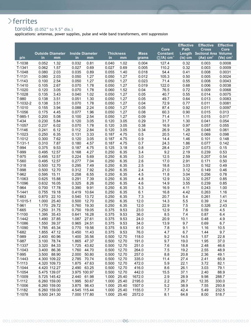
>microwave ferrites and garnetsmaterial characteristics
•gadolinium doped
GD-800 800 75 15.3 < 2.0 280GD-1000 1000 55 15.3 < 2.0 280GD-1200 1200 75 15.2 < 2.0 280GD-1600 1600 50 15.1 < 2.0 280
•gadolinium ans aluminum doped
GA-400 400 78 14.2 < 2.0 150GA-650 650 72 14.6 < 2.0 200GA-800 800 70 14.7 < 2.0 240GA-1000 1000 55 14.7 < 2.0 250GA-1200 1200 55 15.1 < 2.0 260GA-1400 1400 55 15.1 < 2.0 265
•holmium doped
HG-0475 475 130 14.5 < 2.0 225HG-1200 1200 120 15.2 < 2.0 280HG-1600 1600 84 15.1 < 2.0 280
Property Saturation Maximum Dielectric Dielectric CurieMagnetization line width Constant Loss Tangent Temperature
(+/- 5%) (@ 9.4GHz) (@ 9.4GHz)Unit gauss oersted 10-4 ˚CSymbol 4nMs ∆H @ -3dB ε’ tanδδ = ε”/e’ Tc
00110010100010010001000010010001001011000110023000101010010100001001010010010100010010100010
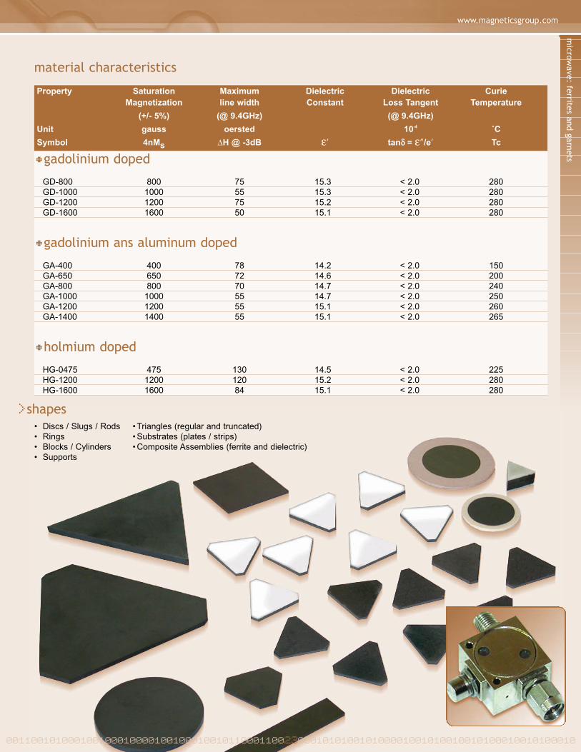
>shapes• Discs / Slugs / Rods • Triangles (regular and truncated)• Rings • Substrates (plates / strips)• Blocks / Cylinders • Composite Assemblies (ferrite and dielectric)• Supports

00110010100010010001000010010001001011000110024000101010010100001001010010010100010010100010
>dielectricsmaterial characteristicsapplications: XXX
K-4 4.3 < 2.0 + 55 2.4 7K-6 6.3 < 2.0 + 107 10.0 9K-9 9.0 < 2.0 + 115 6.0 45K-9.5 9.5 < 1.5 + 100 7.5 25K-12 12.0 < 2.0 + 100 7.5 25K-15 15.0 < 2.0 + 100 7.5 25K-16 16.0 < 2.0 + 120 7.5 10K-18 18.0 < 10.0 + 80 8.0 10K-20 20.0 < 10.0 + 10 8.5 10K-25 25.0 < 10.0 - 125 9.0 10K-30 30.0 < 10.0 - 370 9.2 10K-50 50.0 < 10.0 - 700 9.7 10K-80 80.0 < 10.0 - 980 10.0 10K-100 100.0 < 10.0 - 1100 10.3 10K-140 140.0 < 15.0 - 1200 10.7 10K-160 160.0 < 15.0 - 1250 10.8 10K-250 250.0 < 50.0 - 2600 10.0 10
Property Dielectric Constant Dielectric Coefficient of Coefficient of Thermal(@ 9.4GHz) Loss Dielectric Thermal Conductivity
(+/- 5%) Tangent Constant ExpansionUnit 10-4 ˚C-1 x 10⁻⁶ ˚C-1 x 10⁻⁶ cal/cm2/cm/sec/˚C x 10-3
Symbol ε’ ε”/e’ Tc
>shapes• Rods • Supports• Rings • Substrates (plates/strips)• Blocks / Cylinders • Composite Assemblies (ferrite & dielectric)

www.magneticsgroup.com
00110010100010010001000010010001001011000110025000101010010100001001010010010100010010100010
>dielectric resonatorsmaterial characteristics
>shapes• Discs/Cylinders• Rings• Custom
DR30 – P4 31.0 ± 1 +4 ≥ 10,000 @ 10GHz .076'' to 1.500'' 1.5 – 20.0GHzDR30 – P2 30.5 ± 1 +2 ≥ 10,000 @ 10GHz .076'' to 1.500'' 1.5 – 20.0GHzDR30 – 0 30.0 ± 1 0 ≥ 10,000 @ 10GHz .076'' to 1.500'' 1.5 – 20.0GHzDR30 – N2 29.5 ± 1 -2 ≥ 10,000 @ 10GHz .076'' to 1.500'' 1.5 – 20.0GHzDR36 – P9 36.5 ± 1 +9 ≥ 10,000 @ 10GHz .160'' to 3.500'' 0.8 – 13.5GHzDR36 – P6 36.0 ± 1 +6 35,000 @ 850 MH .160'' to 3.500'' 0.8 – 13.5GHzDR36 – P3 35.7 ± 1 +3 35,000 @ 850 MH .160'' to 3.500'' 0.8 – 13.5GHzDR36 – 0 35.5 ± 1 0 35,000 @ 850 MH .160'' to 3.500'' 0.8 – 13.5GHzDR36 – N3 35.0 ± 1 -3 35,000 @ 850 MH .160'' to 3.500'' 0.8 – 13.5GHzDR45 – P9 46.0± 2 +9 ≥ 10,000 @ 10GHz .160'' to 3.500'' 0.4 – 13.5GHzDR45 – P6 45.5 ± 2 +6 35,000 @ 850 MHz .160'' to 3.500'' 0.4 – 13.5GHzDR45 – P3 45.0 ± 2 +3 35,000 @ 850 MHz .160'' to 3.500'' 0.4 – 13.5GHzDR45 – 0 45.0 ± 2 0 35,000 @ 850 MHz .160'' to 3.500'' 0.4 – 13.5GHzDR45 – N3 45.0 ± 2 -3 35,000 @ 850 MHz .160'' to 3.500'' 0.4 – 13.5GHzDR80 – P9 81.0 ± 2 +9 ≥ 3,000 @ 3GHz .405'' to 1.125'' 0.4 – 4.0GHzDR80 – P6 81.0 ± 2 +6 ≥ 3,000 @ 3GHz .405'' to 1.125'' 0.4 – 4.0GHzDR80 – P3 81.0 ± 2 +3 ≥ 3,000 @ 3GHz .405'' to 1.125'' 0.4 – 4.0GHzDR80 – 0 81.0 ± 2 0 ≥ 3,000 @ 3GHz .405'' to 1.125'' 0.4 – 4.0GHzDR80 – N3 81.0 ± 2 -3 ≥ 3,000 @ 3GHz .405'' to 1.125'' 0.4 – 4.0GHz
Material Dielectric τƒ Unloaded Q Diameter Range AdvisedCode Constant Available Frequency
dielectrics/dielectric resonator: material characteristics
Notes:1. all tƒ specifications are measured between 25° to 60°C using a standard cavity2. all materials are available in ±1 ppm/°C and ±2 ppm/°C tolerance, except DR8O which is available only in ±2 ppm/°C tolerance

00110010100010010001000010010001001011000110026000101010010100001001010010010100010010100010
>advanced materialsapplications: aircraft turbine blades, environmental coatings, industrial turbine blades, automotive components
•powdersFeatures
• Fully Reacted• Flowable• Sintered Sprayed Powder• Controlled Composition• High Purity
Benefits
• Improved Process Yields• Consistent Mechanical and Chemical
Performance• Improved Deposition Efficiency
•ignotsFeatures
• Controlled Density (part to partvariation ± 0.2 g/cc)
• Fully Reacted• Uniform Grain and Pore Size
Distribution• Controlled Composition
Benefits
• Uniform Melting• Improved Process Repeatability• Minimum Degassing And Spitting
•specialty ceramics• Semi-conducting Oxides• Hydroxylapatite• Others
advanced materials | engineering notes
>engineering notes
00110010100010010001000010010001001011000110027000101010010100001001010010010100010010100010

00110010100010010001000010010001001011000110028000101010010100001001010010010100010010100010
>engineering notes

engineering notes | orderingwww.magneticsgroup.com
00110010100010010001000010010001001011000110029000101010010100001001010010010100010010100010
>ordering
>national magnetics group / tci ceramicsManufacturers of technical ceramics (magnetic and advanced materials) and powdered iron cores.
>corporate headquarters1210 Win Drive, Bethlehem, Pennsylvania 18017-7061 USAT: 610-867-7600 | F: 610-867-0200
>manufacturing facilities1210 Win Drive, Bethlehem, Pennsylvania 18017 USA18450 Showalter Road, Hagerstown, Maryland 21742 USA
>urlwww.magneticsgroup.com
>emailFerrites and Magnets: [email protected] and Advanced Materials: [email protected]

Manufacturing Facilities1210 Win Drive | Bethlehem, Pennsylvania 18017 | USA18450 Showalter Road | Hagerstown, Maryland 21742 | USA
Corporate Headquarters1210 Win Drive | Bethlehem, Pennsylvania 18017-7061 | USA
T 610.867.7600 | F 610.867.0200