National Grid UK Electricity Transmission plcclear sheath), ends crimped with ESI/T1 compression...
169
National Grid UK Electricity Transmission plc NGUK/PM/ETSR/NSI/26/GN Issue 3 National Safety Instruction and Guidance © National Grid plc 2016 – All Rights Reserved Uncontrolled when printed National Grid UK Electricity Transmission plc Uncontrolled when printed NATIONAL SAFETY INSTRUCTION and Guidance NSI 26 RAILWAY CONNECTION CIRCUITS Copyright National Grid plc 2016 ©, all rights reserved. No part of this publication may be reproduced, stored in a retrieval system, or transmitted in any form or by any means electronic, mechanical, photocopying, recording or otherwise, without the written permission of National Grid obtained from the issuing location. The contents of National Grid documents are based on the needs of National Grid and the conditions under which it operates. It shall not therefore be assumed that the contents stated therein necessarily meet the particular circumstances and requirements of other organisations. The principles set out in this document are for information only and therefore National Grid is not liable to any third party for any loss or damage resulting from reliance on the contents. It is the responsibility of such external organisations to check that the document is the latest version and is appropriate for their purposes.
Transcript of National Grid UK Electricity Transmission plcclear sheath), ends crimped with ESI/T1 compression...
National Grid UK Electricity Transmission plc NGUK/PM/ETSR/NSI/26/GN Issue 3 National Safety Instruction and Guidance
© National Grid plc 2016 – All Rights Reserved
Uncontrolled when printed
National Grid UK Electricity Transmission plc
Uncontrolled when printed
NATIONAL SAFETY INSTRUCTION
and
Guidance
NSI 26 RAILWAY CONNECTION CIRCUITS
Copyright National Grid plc 2016 ©, all rights reserved. No part of this publication may be reproduced, stored in a retrieval system, or transmitted in any form or by any means electronic, mechanical, photocopying, recording or otherwise, without the written permission of National Grid obtained from the issuing location.
The contents of National Grid documents are based on the needs of National Grid and the conditions under which it operates. It shall not therefore be assumed that the contents stated therein necessarily meet the particular circumstances and requirements of other organisations. The principles set out in this document are for information only and therefore National Grid is not liable to any third party for any loss or damage resulting from reliance on the contents. It is the responsibility of such external organisations to check that the document is the latest version and is appropriate for their purposes.
National Grid UK Electricity Transmission plc NGUK/PM/ETSR/NSI/26/GN Issue 3 National Safety Instruction and Guidance
© National Grid plc 2016 – All Rights Reserved Page i of ii
Uncontrolled when printed
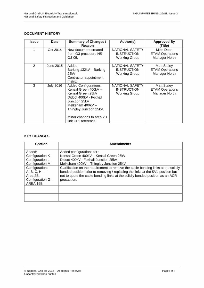
DOCUMENT HISTORY
Issue Date Summary of Changes / Reason
Author(s) Approved By (Title)
1 Oct 2014 New document created from G3 procedure NS-G3-05.
NATIONAL SAFETY INSTRUCTION Working Group
Mike Dean ETAM Operations
Manager North
2 June 2015 Added: Barking 132kV – Barking 25kV Contractor appointment matrix
NATIONAL SAFETY INSTRUCTION Working Group
Matt Staley ETAM Operations
Manager North
3 July 2016 Added Configurations: Kensal Green 400kV – Kensal Green 25kV Didcot 400kV - Foxhall Junction 25kV Melksham 400kV – Thingley Junction 25kV. Minor changes to area 2B link CL1 reference
NATIONAL SAFETY INSTRUCTION Working Group
Matt Staley ETAM Operations
Manager North
KEY CHANGES
Section Amendments
Added: Configuration K Configuration L Configuration M
Added configurations for : Kensal Green 400kV – Kensal Green 25kV Didcot 400kV - Foxhall Junction 25kV Melksham 400kV – Thingley Junction 25kV
Configurations A, B, C, H – Area 2B. Configuration G - AREA 16B
Clarification on the requirement to remove the cable bonding links at the solidly bonded position prior to removing / replacing the links at the SVL position but not to quote the cable bonding links at the solidly bonded position as an ACR precaution.

National Grid UK Electricity Transmission plc NGUK/PM/ETSR/NSI/26/GN Issue 3 National Safety Instruction and Guidance
© National Grid plc 2016 – All Rights Reserved Page ii of ii
Uncontrolled when printed
RAILWAY CONNECTION CIRCUITS
CONTENTS Page
1 Purpose and Scope
1
2 Definitions 2
3 Dangers 4
4 Control of Alternative Current Return (ACR) current
5
5 Switching and establishing ACR safety precautions
11
6 Management of Links
14
7 Inadvertent ACR current parallel paths 17
8 Working on Cables 18
9 Testing 18
Appendix A Example of a completed Safety Document. Appendix B Switching Instructions for Railway Connection Circuits Appendix C Configurations Index Appendix D Authorisation Matrix for Contractors Personnel
19
20
24
166
National Grid UK Electricity Transmission plc NGUK/PM/ETSR/NSI/26/GN Issue 3 National Safety Instruction and Guidance
© National Grid plc 2016 – All Rights Reserved Page 1 of 166
Uncontrolled when printed
1 Purpose and Scope
To apply the principles established by the Safety Rules and provide guidance on National Safety
Instruction 26 when applying the principles to achieve safety from Alternative Conductor Return ACR Current(s) for Personnel, working on Railway Connection Circuit(s). National Safety Instruction 26 gives direction on:
The avoidance of ACR Current(s) and earth fault current(s) which could potentially harm Personnel when locally switching or single circuit working on Equipment associated with multiple railway connection circuits
Establishing safety from ACR Current(s) when working on cables associated with Railway Connection Circuit(s).
The procedure for removal and replacement of the neutral link and the limitation of alternative ACR Current(s) whilst operating the neutral link
Management of the cross boundary interface with the Railway Connection Circuit(s) operator shall be achieved in accordance with the Grid Code OC8; a site specific G38 procedure and UK/BP/SE/301 Managing Safety Interfaces.
If all Railway Connection Circuit(s) at a site supplying a common railway supply point are out of service and a safe system of work established to ensure that this situation will continue throughout the period of the works, then there is no Danger of ACR Current(s). When undertaking safety switching and Safety Document procedures to establish ACR precautions on Railway Connection Circuit(s), this shall be undertaken by a Senior Authorised Person and Control Person (Safety) appointed to this National Safety Instruction.
The normal operating voltage of a Railway Connection Circuit(s) Neutral Conductor is nominally zero volts, hence under the National Grid UK Electricity Transmission safety rules this conductor is not classified as HV although it does form part of National Grid’s HV System. Technical report TR(E) 483 ‘Railway 25kV Neutral Conductor: Isolation and Earthing during Maintenance’ identifies that in order to comply with the National Grid UK Electricity Transmission Safety Rules, The Electricity at Work Regulations 1989 and to protect Personnel; Point(s) of Isolation shall be established on the neutral conductor. At some sites the design of Equipment includes the Auxiliary Pole (A Pole), Catenary Pole (C Pole) and Neutral Conductor on the same structure. For this type of Equipment when establishing Point(s) of Isolation / Primary Earth on the Auxiliary Pole (A Pole) and Catenary Pole (C Pole), Point(s) of Isolation / Primary Earth are also created on the Neutral Conductor.
The layout of this guidance note reflects that of legislative codes of practice, where the rule (or mandatory obligation) is identified by a green panel on the left-hand side. The guidance follows after the rule and is identified by a blue panel. Within National Grid the guidance notes hold equivalent status of an Approved Code of Practice (ACOP) in law. If not followed, you will be required to demonstrate that your safe system of work is of an equal or higher standard.
National Grid UK Electricity Transmission plc NGUK/PM/ETSR/NSI/26/GN Issue 3 National Safety Instruction and Guidance
© National Grid plc 2016 – All Rights Reserved Page 2 of 166
Uncontrolled when printed
2 Definitions
Terms printed in bold type are as defined in the Safety Rules.
Title Definition
Alternative Conductor Return (ACR) current
Return current carried by a National Grid conductor or cable sheath, which is not the Neutral Conductor of the supplying transformer
Auto Transformer (AT) Mode A connection arrangement where both the A pole and the C pole busbars are energised and capable of providing a supply to the rail operator
Booster Transformer (BT) Mode A connection arrangement where only the C Pole busbar is energised and providing a supply to the rail operator. The A pole, if present, will be disconnected from the transformer and connected to earth by a permanent earth connection, usually within the 25 kV substation
Configuration A connection arrangement that can apply to more than one substation.
Earth Bond(s)
A type registered bridging connection used for the purpose of providing earth continuity on earth connections. They are clear in colour and are fully fault rated when applied in appropriate numbers. Type A - An Earth Bond consisting of; two CE 20 earth end clamps supplied with one 150 mm
2 Aluflex lead
(clear sheath), ends crimped with ESI/T1 compression terminations.
Earth Continuity Conductor (ECC) An earth bond that extends from the substation earth mat to bond cable link boxes along the cable route
Earthing Restriction Zone A zone where the earthing of any conductors or Equipment has been restricted for the prevention of ACR Current(s)
Intermediate Neutral Earth (INE) A permanent earth applied to the Neutral Conductor at an intermediate point between the transformer and the railway neutral earthing points
Making Equipment Available Removing the safety precautions taken to create a Point of Immobilisation
Neutral Conductor The designated return conductor for the Catenary and Auxiliary Poles i.e. C-N & A-N connections
Pole One of, Auxiliary Pole (A Pole) or, Catenary Pole (C Pole)
Auxiliary Pole (A Pole) A 25 kV to neutral supply i.e. A-N connection, with a 180 degree phase angle separation from the Catenary Pole of the same transformer. This pole does not exist on a BT Mode
Catenary Pole (C Pole) A 25 kV to neutral supply (C-N connection)
Point of Immobilisation The point at which Equipment has been Locked open to establish safety precautions to prevent ACR Current(s). A Point of Immobilisation notice shall be attached.
Railway Connection Circuit A National Grid circuit identified in Appendix C providing a connection to a rail operators system
Radial Earth An earth bond that extends from a substation earth mat to manage the characteristic of the rise of earth potential contours.

National Grid UK Electricity Transmission plc NGUK/PM/ETSR/NSI/26/GN Issue 3 National Safety Instruction and Guidance
© National Grid plc 2016 – All Rights Reserved Page 3 of 166
Uncontrolled when printed
Temporary Earth Bond(s)
A type registered bridging connection used as an initial connection to eliminate Danger on any Inadequate System. Leads are coloured blue and Consists of two 50mm
2
Aluflex leads (blue sheathed), ends crimped and affixed with a CE20/2 earth end clamp and a CE57 earth end clamp.
Temporary Earth Bond Pole A type registered device for the application of Temporary Earth Bond(s).

National Grid UK Electricity Transmission plc NGUK/PM/ETSR/NSI/26/GN Issue 3 National Safety Instruction and Guidance
© National Grid plc 2016 – All Rights Reserved Page 4 of 166
Uncontrolled when printed
3 Dangers
The main Dangers to Personnel from operating HV Equipment at Railway Connection Circuit(s) are electric shock, burns and effects on eyes arising from the inadvertent connection of separate earthing systems due to:
The application / removal of an Earthing Device to Equipment capable of carrying ACR current, earth fault current and induced current.
The connection or disconnection of Equipment capable of carrying ACR current or earth fault current.
The opening or closing of a neutral link, Intermediate Neutral Earth, cable sheath or earth capable of ACR current.
The inadvertent connection or disconnection of earthing systems.
National Grid UK Electricity Transmission plc NGUK/PM/ETSR/NSI/26/GN Issue 3 National Safety Instruction and Guidance
© National Grid plc 2016 – All Rights Reserved Page 5 of 166
Uncontrolled when printed
NSI 26 4.1 to 4.5
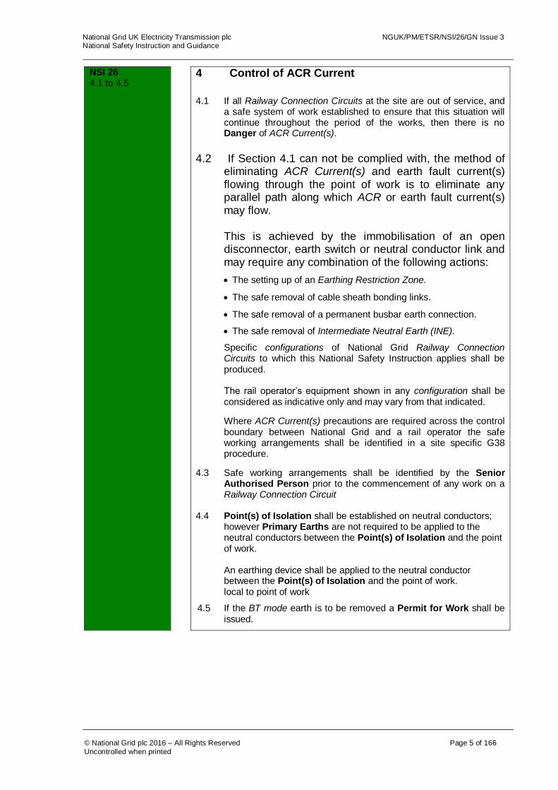
4 Control of ACR Current
4.1 If all Railway Connection Circuits at the site are out of service, and
a safe system of work established to ensure that this situation will continue throughout the period of the works, then there is no Danger of ACR Current(s).
4.2 If Section 4.1 can not be complied with, the method of
eliminating ACR Current(s) and earth fault current(s) flowing through the point of work is to eliminate any parallel path along which ACR or earth fault current(s) may flow.
This is achieved by the immobilisation of an open disconnector, earth switch or neutral conductor link and may require any combination of the following actions:
The setting up of an Earthing Restriction Zone.
The safe removal of cable sheath bonding links.
The safe removal of a permanent busbar earth connection.
The safe removal of Intermediate Neutral Earth (INE).
Specific configurations of National Grid Railway Connection Circuits to which this National Safety Instruction applies shall be produced. The rail operator’s equipment shown in any configuration shall be considered as indicative only and may vary from that indicated.
Where ACR Current(s) precautions are required across the control boundary between National Grid and a rail operator the safe working arrangements shall be identified in a site specific G38 procedure.
4.3 Safe working arrangements shall be identified by the Senior Authorised Person prior to the commencement of any work on a Railway Connection Circuit
4.4 Point(s) of Isolation shall be established on neutral conductors;
however Primary Earths are not required to be applied to the neutral conductors between the Point(s) of Isolation and the point of work.
An earthing device shall be applied to the neutral conductor
between the Point(s) of Isolation and the point of work. local to point of work
4.5 If the BT mode earth is to be removed a Permit for Work shall be issued.

National Grid UK Electricity Transmission plc NGUK/PM/ETSR/NSI/26/GN Issue 3 National Safety Instruction and Guidance
© National Grid plc 2016 – All Rights Reserved Page 6 of 166
Uncontrolled when printed
Guidance NSI 26 4.1 to 4.2
4 Control of ACR Current 4.1 To avoid any possibility of ACR current(s) at the point of work and
to ensure a safe system of work is maintained, Point(s) of Isolation on each adjacent Railway Connection Circuit shall be established. If the Point(s) of Isolation are located on the LV side of the connection transformer then, to avoid danger from fault return current through the point of work, the Point(s) of Isolation shall be located on the same earth mat as the connection transformer. Figure 4.1A illustrates the required position of the Point(s) of Isolation.
The Point(s) of Isolation on each adjacent Railway Connection Circuit shall be recorded in Section 2 of the Safety Document.
Note: 8T3 is on the same earth mat as SGT8
Figure 4.1A – Point(s) of Isolation on each adjacent Railway Connection Circuit
4.2 For new National Grid Railway Connection Circuits it is preferable
that one of the existing layout configurations is chosen at the design stage. If the new Railway Connection Circuit does not match one of the existing arrangements the commissioning panel chairman shall be responsible for producing a set of Specific configurations, work areas and precautions to be taken.
For a new Railway Connection Circuit that matches an existing
configuration the name of the Location shall be added to the table in Appendix C.
The new configuration shall be submitted to Safety Rules
Assurance Team for re-issue of the NSI a minimum of 6 months before commissioning.
Work
occurring on this circuit with
adjacent circuit also out of
service
Points of Isolation required here
or….
or Point of Isolation required
here.

National Grid UK Electricity Transmission plc NGUK/PM/ETSR/NSI/26/GN Issue 3 National Safety Instruction and Guidance
© National Grid plc 2016 – All Rights Reserved Page 7 of 166
Uncontrolled when printed
Guidance NSI 26 4.3
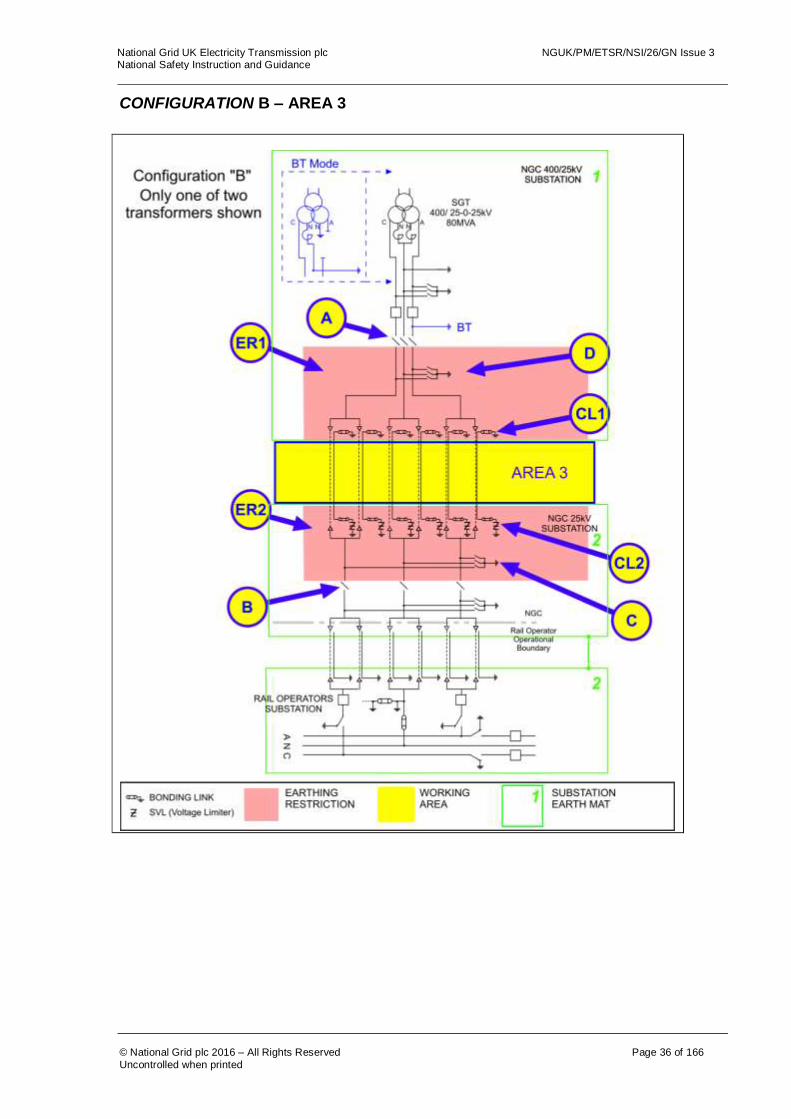
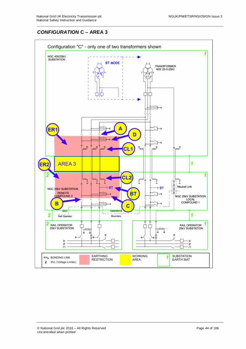
4.3 Appendix C identifies the safe working areas for each configuration and includes the pole and neutral line diagram for one Railway Connection Circuit only. An example is given below in Figure 4.3A
The Equipment arrangement for permanent BT Mode operation is shown in blue. This includes an additional fixed earth on the A pole, also annotated in blue.
The areas to be controlled by the safe working arrangements are numbered and shown boxed in yellow with a blue border. Earth mats are shown in green and numbered; any interconnection between each earth mat is shown. Precaution required to be taken to avoid ACR current are identified as Blue circles with a yellow background and are detailed in the attached schedule. The Earthing Restriction Zone is identified in pink shading.
Figure 4.3A – Example of safe working arrangement diagrams

National Grid UK Electricity Transmission plc NGUK/PM/ETSR/NSI/26/GN Issue 3 National Safety Instruction and Guidance
© National Grid plc 2016 – All Rights Reserved Page 8 of 166
Uncontrolled when printed
Guidance NSI 26 4.3 cont
For work on a cable the Senior Authorised Person shall make a decision as to which work area applies.
If there is any possibility of contact with a cable sheath bonded to a separately earthed site then the work area chosen shall be the one that includes the cable sheath connections. Figure 4.3B identifies the boundary of the work areas and the decision as to which work area to be used.
Figure 4.3B example of decision of work area when working in proximity to
cable sheath bonding Where works on a cable system are near to the boundary of a substation earth mat, or an extension to this such as an ECC, then a decision on work area shall be based on:
a) Where there is a possibility of bridging between the point of work and the substation earth mat the arrangement for working on the cable sealing ends shall be used, in the example above this would be AREA 2B. This includes where the substation earth mat is extended via the radial earth or ECC.
b) Where it is not practicable to run a remote earth connection to the point of work from the nearest earth mat and it is not possible for anything to bridge the gap, the works shall be deemed to be in area associated with the cable (AREA 3).
Note: for Area 2B and 3 refer to the substation specific configuration diagrams in APPENDIX C
Work shall only occur in one AREA at a time to avoid any conflict between ACR current precautions. However in the above scenario working in AREA 2B by default also includes work in AREA 2A.
If work is in AREA 2A but in close proximity to the cable sheath bonding, AREA 2B shall be used.

National Grid UK Electricity Transmission plc NGUK/PM/ETSR/NSI/26/GN Issue 3 National Safety Instruction and Guidance
© National Grid plc 2016 – All Rights Reserved Page 9 of 166
Uncontrolled when printed
Guidance NSI 26 4.4
4.4 The normal operating voltage of a Railway Connection Circuit(s) Neutral Conductor is nominally zero volts, hence under the National Grid UK Electricity Transmission Safety Rules this conductor is not classified as HV although it does form part of National Grid’s HV System.
Technical report TR(E) 483 ‘Railway 25kV Neutral Conductor: Isolation and Earthing during Maintenance’ identifies, that in order to comply with the National Grid UK Electricity Transmission Safety Rules, The Electricity at Work Regulations 1989 and to protect Personnel; Point(s) of Isolation shall be established on the neutral conductor. In addition the report identifies there is no addition protection afforded by the application of Primary Earths to the neutral conductor. In some cases the application of Primary Earths, will introduce a hazard into the work area arising from the risk of rise of earth potential following a fault on the railway system. However the report identifies the neutral conductor shall be earthed locally by the application of an Earthing Device. A Drain Earth is suitable for this application. A Point(s) of Isolation established on the neutral may also be a Point of Immobilisation under this procedure. If the Point(s) of Isolation on the neutral also establishes Point(s) of Isolation on the phase conductors the Point(s) of Isolation may not satisfy the requirement for the phase conductors as Primary Earths can not be applied between the Point(s) of Isolation and the point of work. In this case the Point(s) of Isolation shall be identified as for the neutral conductor only by identifying the Point(s) of Isolation on the document as for the neutral only. In Figure 4.4 below, Point(s) of Isolation for the phase conductors can be established on the disconnectors in the rail operator substation (disconnector D) and primary earthing can be achieved by the application of the 25kV site earth switch (earth switch E). As there is no requirement on the neutral conductor to apply Primary Earths between the Point(s) of Isolation and the point of work, disconnector B can be used as a Point(s) of Isolation in preference to removing the neutral link in the rail operator substation. However, disconnector B could not be used as Point(s) of Isolation for the phase conductors as Primary Earths would be required to be applied in the earthing restriction zone ER2. The Point of Isolation for the neutral, disconnector B, shall be identified on the safety document as [disconnector number] (Neutral Only) e.g. in section 2 of the safety document:
“1L3 (Neutral Only)” In this arrangement disconnector B is also a point of immobilisation.

National Grid UK Electricity Transmission plc NGUK/PM/ETSR/NSI/26/GN Issue 3 National Safety Instruction and Guidance
© National Grid plc 2016 – All Rights Reserved Page 10 of 166
Uncontrolled when printed
Guidance NSI 26 4.4 cont.
Figure 4.4 An example of Point(s) of Isolation on the neutral conductor only.
D D
E
National Grid UK Electricity Transmission plc NGUK/PM/ETSR/NSI/26/GN Issue 3 National Safety Instruction and Guidance
© National Grid plc 2016 – All Rights Reserved Page 11 of 166
Uncontrolled when printed
NSI 26 5.1 to 5.6
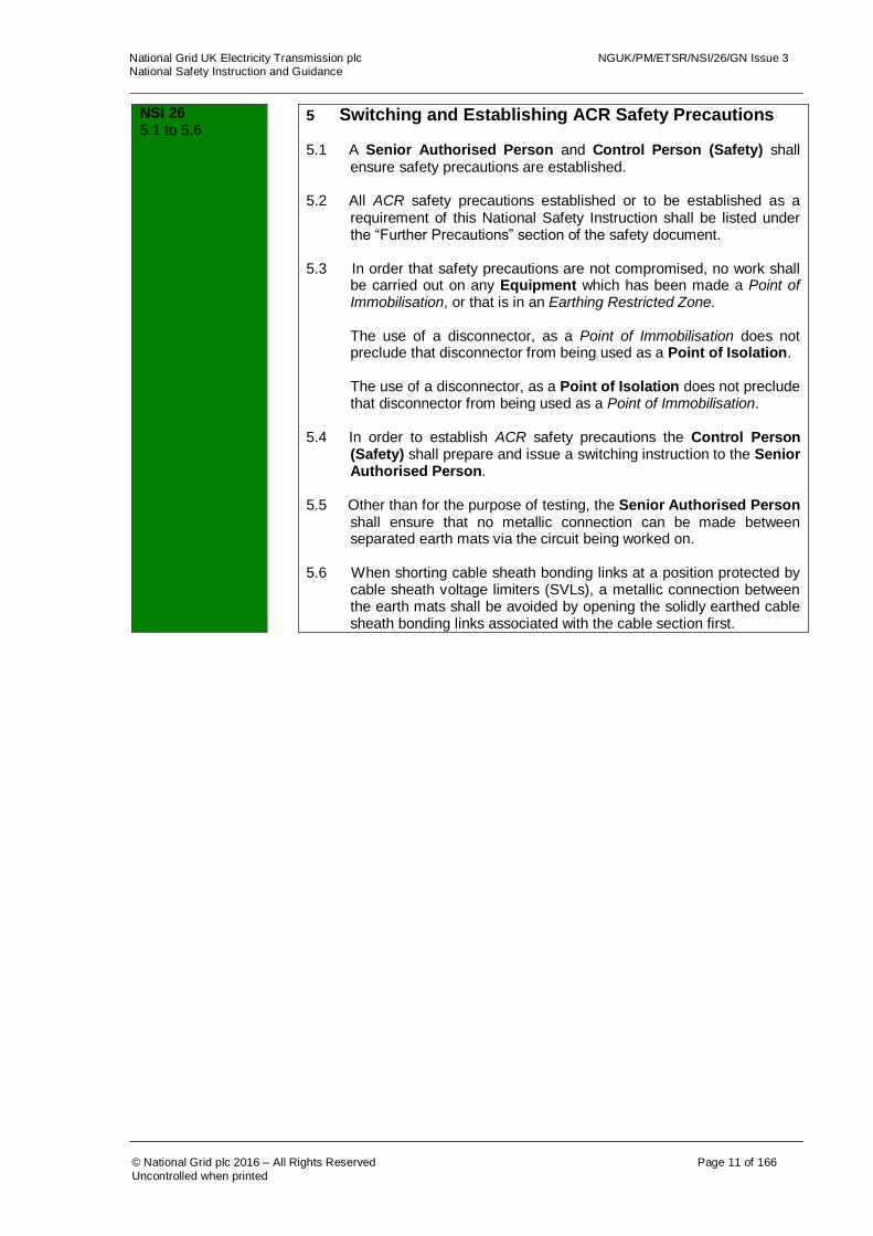
5 Switching and Establishing ACR Safety Precautions
5.1 A Senior Authorised Person and Control Person (Safety) shall
ensure safety precautions are established. 5.2 All ACR safety precautions established or to be established as a
requirement of this National Safety Instruction shall be listed under the “Further Precautions” section of the safety document.
5.3 In order that safety precautions are not compromised, no work shall
be carried out on any Equipment which has been made a Point of Immobilisation, or that is in an Earthing Restricted Zone.
The use of a disconnector, as a Point of Immobilisation does not preclude that disconnector from being used as a Point of Isolation. The use of a disconnector, as a Point of Isolation does not preclude that disconnector from being used as a Point of Immobilisation.
5.4 In order to establish ACR safety precautions the Control Person
(Safety) shall prepare and issue a switching instruction to the Senior Authorised Person.
5.5 Other than for the purpose of testing, the Senior Authorised Person
shall ensure that no metallic connection can be made between separated earth mats via the circuit being worked on.
5.6 When shorting cable sheath bonding links at a position protected by
cable sheath voltage limiters (SVLs), a metallic connection between the earth mats shall be avoided by opening the solidly earthed cable sheath bonding links associated with the cable section first.

National Grid UK Electricity Transmission plc NGUK/PM/ETSR/NSI/26/GN Issue 3 National Safety Instruction and Guidance
© National Grid plc 2016 – All Rights Reserved Page 12 of 166
Uncontrolled when printed
Guidance NSI 26 5.1 to 5.2
5 Switching and establishing ACR safety precautions 5.1 To enable the Control Person (Safety) function to be adequately
managed a Job Information Form (JIF) or a draft Permit for Work shall be forwarded to the .box.noc.planning email address at least 72 hours before safety precautions / safety documents are required.
This notification will detail all safety precautions, a description of the work to be undertaken and the work area, as defined within this National Safety Instruction, applicable to the requested safety document. For an emergency situation the 72 hour notice can be reduced with the agreement of the Senior Authorised Person and the Transmission Network Control Centre (TNCC).
5.2 The “Further Precautions” section of the Safety Document shall
detail:
1. The configuration letter and area number to which the ACR current precautions have been established.
2. The nomenclature of the Equipment which the ACR current
precautions have been applied. Appendix A gives an example of a completed Safety Document. In order to comply with the above requirements and the safety rules, the following process has been identified for the removal of any cable sheath bonding links that can be removed without the need for all the Railway Connection Circuits to be out of service:
• The ACR precautions required to be established at a cable sheath bonding link box will be referenced in the further precautions section of the Safety Document as links to be removed prior to the work commences.
The Further precautions section of the Safety Document shall be completed with the following statement: “Ensure cable Sheath Bonding Links XYZ are removed before work commences.” Where, XYZ is the reference to the cable sheath link in the appropriate configuration.
• The Senior Authorised Person will initially receive the
Safety Document and without delay shall establish the ACR safety precautions on the cable sheath bonding links using the NSI 5 or NSI 24 type registered equipment as appropriate.
National Grid UK Electricity Transmission plc NGUK/PM/ETSR/NSI/26/GN Issue 3 National Safety Instruction and Guidance
© National Grid plc 2016 – All Rights Reserved Page 13 of 166
Uncontrolled when printed
Guidance NSI 26 5.2 cont. to 5.6
• Once all the ACR precautions are established, the Safety Document can then be transferred to the Competent Person undertaking the work. The Senior Authorised Person shall complete a status of transfer form stating in section 2 that the “Cable Sheath Bonding Links XYZ have been removed”. Any additional safety keys shall be retained with the safety document and identified on the status of transfer form.
• Before the cancellation of the last Safety Document
issued quoting cable Sheath Bonding Links established as ACR precautions, the Senior Authorised Person shall ensure the cable Sheath Bonding Links are replaced to the operational state.
WARNING, some arrangements where the cable sheath solidly
bonds two remote earth mats requires all the Railway Connection Circuits to be out of service at that Location before the removal of the cable sheath links. Follow any warnings identified in the appropriate configuration and precautions to be taken table.
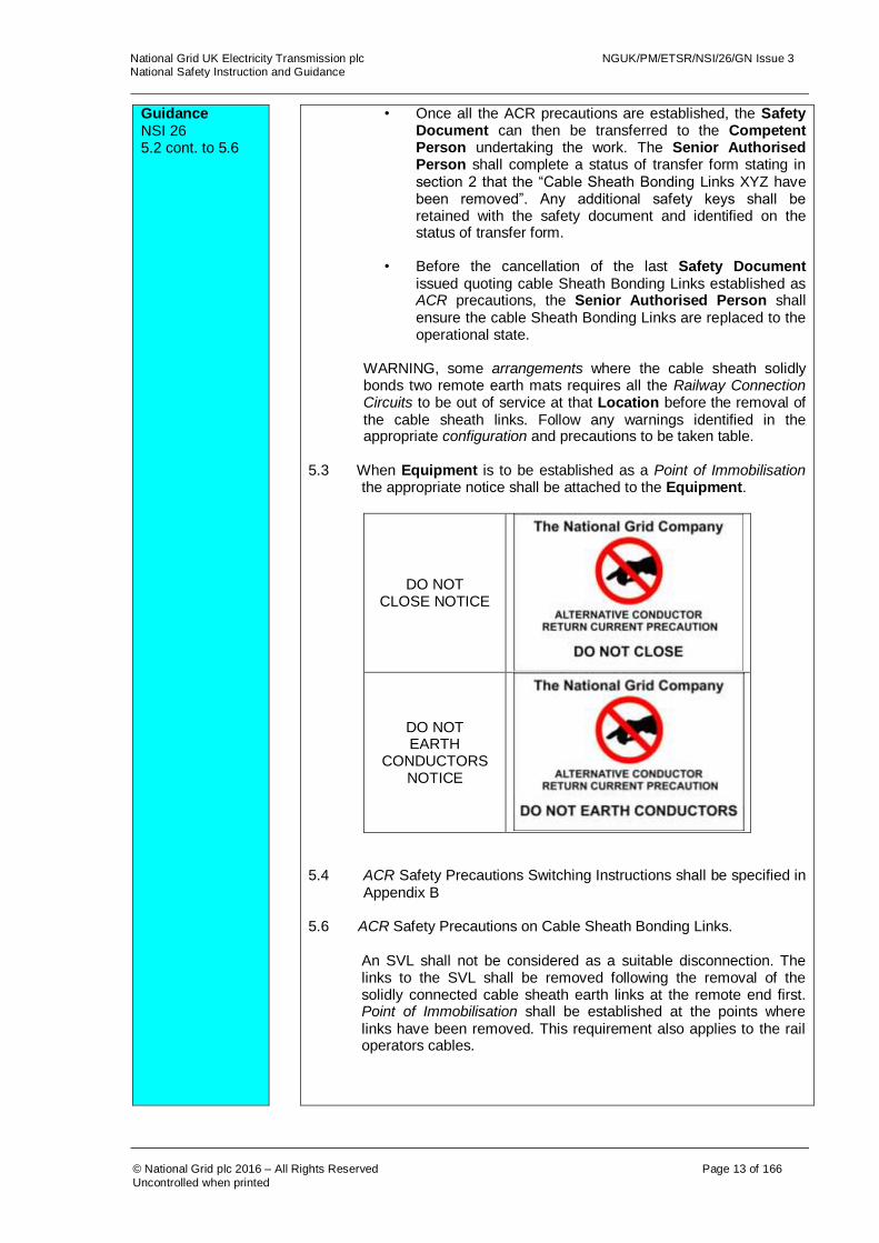
5.3 When Equipment is to be established as a Point of Immobilisation
the appropriate notice shall be attached to the Equipment.
DO NOT CLOSE NOTICE
DO NOT EARTH
CONDUCTORS NOTICE
5.4 ACR Safety Precautions Switching Instructions shall be specified in
Appendix B
5.6 ACR Safety Precautions on Cable Sheath Bonding Links.
An SVL shall not be considered as a suitable disconnection. The links to the SVL shall be removed following the removal of the solidly connected cable sheath earth links at the remote end first. Point of Immobilisation shall be established at the points where links have been removed. This requirement also applies to the rail operators cables.

National Grid UK Electricity Transmission plc NGUK/PM/ETSR/NSI/26/GN Issue 3 National Safety Instruction and Guidance
© National Grid plc 2016 – All Rights Reserved Page 14 of 166
Uncontrolled when printed
NSI 26 6.1 to 6.4
6. Management of Links 6.1 In order to prevent Danger from ACR current and Impressed Voltage
conditions:
Before a neutral link is removed a Temporary Earth Bond shall be applied either side of the neutral link.
Before an INE link is removed a Temporary Earth Bond shall be applied to the Neutral Conductor side.
Before a cable sheath bonding link(s) is removed, a Temporary Earth Bond shall be applied to the cable sheath bonding link(s) by the Senior Authorised Person
Removal of cable sheath bonding link(s) outside the substation shall be carried out in accordance with NSI 5 “Cable Systems”.
Where the 25-0-25kV transformer winding is Earthed on the railway operator’s earth mat and this is separate to the National Grid earth mat, the railway operator shall remove the earth from the Neutral Conductor before the National Grid neutral link is removed.
6.2 When carrying out work that is not removing links in the substation
cable sheath bonding link box, the Temporary Earth Bond shall be replaced with the correct number of Type A Earth Bond(s) attached across the link to earth by the Senior Authorised Person.
6.3 When restoring the neutral link, INE or cable sheath bonding link(s)
the reverse of this procedure shall be employed. 6.4 When shorting across cable sheath bonding links at a position
protected by cable sheath voltage limiters (SVLs), the cable bonding links at the solidly bonded position shall be removed prior to removing the links, or SVLs, at the SVL link box position.
National Grid UK Electricity Transmission plc NGUK/PM/ETSR/NSI/26/GN Issue 3 National Safety Instruction and Guidance
© National Grid plc 2016 – All Rights Reserved Page 15 of 166
Uncontrolled when printed
Guidance NSI 26 6.1
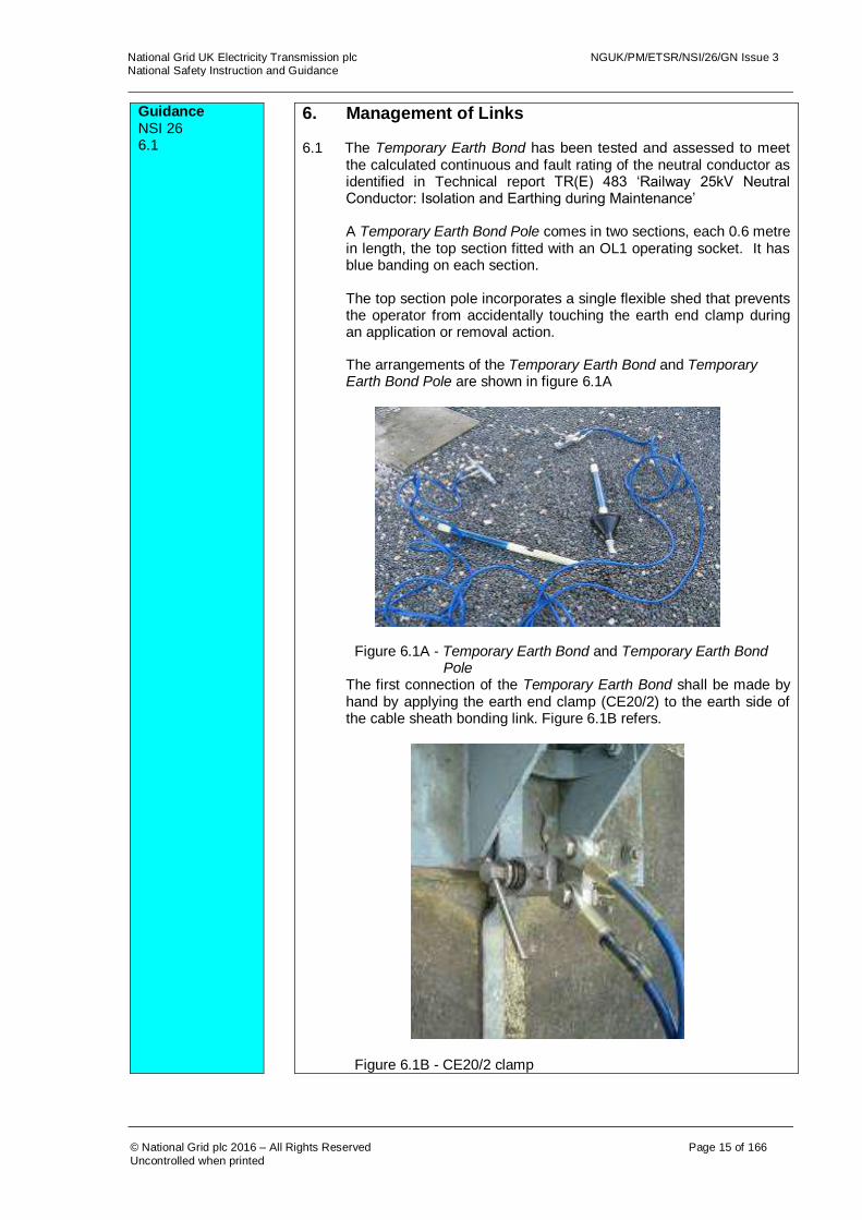
6. Management of Links 6.1 The Temporary Earth Bond has been tested and assessed to meet
the calculated continuous and fault rating of the neutral conductor as identified in Technical report TR(E) 483 ‘Railway 25kV Neutral Conductor: Isolation and Earthing during Maintenance’
A Temporary Earth Bond Pole comes in two sections, each 0.6 metre in length, the top section fitted with an OL1 operating socket. It has blue banding on each section. The top section pole incorporates a single flexible shed that prevents the operator from accidentally touching the earth end clamp during an application or removal action. The arrangements of the Temporary Earth Bond and Temporary Earth Bond Pole are shown in figure 6.1A
Figure 6.1A - Temporary Earth Bond and Temporary Earth Bond Pole The first connection of the Temporary Earth Bond shall be made by hand by applying the earth end clamp (CE20/2) to the earth side of the cable sheath bonding link. Figure 6.1B refers.
Figure 6.1B - CE20/2 clamp

National Grid UK Electricity Transmission plc NGUK/PM/ETSR/NSI/26/GN Issue 3 National Safety Instruction and Guidance
© National Grid plc 2016 – All Rights Reserved Page 16 of 166
Uncontrolled when printed
Guidance NSI 26 6.1 cont to 6.2
The second connection to make the bridge complete will be done by applying the CE57 clamp of the Temporary Earth Bond using the supplied Temporary Earth Bond Pole onto the sheath side of the cable sheath bonding link. Figure 6.1C refers.
Figure 6.1C - Temporary Earth Bond
Prior to the removal or replacement of the National Grid neutral link, and provided the National Grid neutral link is positioned within the same earthing mat as the rail operator, there is no requirement isolate the railway operator’s neutral links prior to issuing the switching instruction to remove the National Grid neutral link. Where the National Grid earth mat and the rail operator’s earth mat are not connected, the railway operator’s neutral earth connection and neutral link must be removed and maintained prior to the removal the National Grid neutral link.
6.2 When carrying out work that is not removing links in the substation cable sheath bonding link box a Temporary Earth Bond shall be applied, followed by the appropriate numbers of Type A Earth Bond(s) as soon as is reasonably practical by the Senior Authorised Person. The number of Type A Earth Bond(s) to be applied shall achieve the fault rating / circulating current capacity as defined within NSI 2 - “Earthing High Voltage Equipment”.
After the appropriate number of Type A Earth Bond(s) are applied the Temporary Earth Bond can be removed.

National Grid UK Electricity Transmission plc NGUK/PM/ETSR/NSI/26/GN Issue 3 National Safety Instruction and Guidance
© National Grid plc 2016 – All Rights Reserved Page 17 of 166
Uncontrolled when printed
NSI 26 7.1
7. Inadvertent ACR Current Parallel Paths
7.1 When a National Grid transformer winding is locally earthed and an
inadvertent connection between separate earth systems is made, an ACR and earth fault current parallel path will be established and ACR current(s) will flow.
If a parallel path has been established the Senior Authorised Person shall check that the in-service Railway Connection Circuit Neutral Conductor has not been compromised. If the in service Railway Connection Circuit Neutral Conductor has been compromised then the associated in service circuit Railway Connection Circuit shall be removed from service before removing the parallel path. Under these circumstances load current shall not be broken by the opening of a disconnector. This applies whether or not the disconnector has been fitted with bus transfer duty contacts. If the in service Railway Connection Circuit Neutral Conductor has not been compromised the Senior Authorised Person shall liaise with the appropriate Control Person to either:
Break the parallel path using a disconnector with a suitable bus transfer duty rating.
Or open a standard disconnector once all associated railway connection circuits have been switched out of service.
Guidance NSI 26 7.1
7. Inadvertent ACR Current Parallel Paths
7.1 When a National Grid transformer winding at a Location is remotely
Earthed via the rail operator’s earth mat, and this is separated from the National Grid earth mat, then the circuit configuration is such that ACR Current will not flow. However the segregation of earth mats is required to manage rise of earth potential issues and any inadvertent connection shall be removed as soon as possible.
An example of an inadvertent connection could be by the application
of Earthing Device(s) so they connect two separate earth mats together.
The integrity of the in service Railway Connection Circuit Neutral Conductor can be checked by establishing that a measurable current is flowing in the in-service neutral by the use of a clip on ammeter around the neutral conductor or indirectly via the CT or relay of the in-service neutral.

National Grid UK Electricity Transmission plc NGUK/PM/ETSR/NSI/26/GN Issue 3 National Safety Instruction and Guidance
© National Grid plc 2016 – All Rights Reserved Page 18 of 166
Uncontrolled when printed
NSI 26 8.1
8. Working on Cables 8.1 When working on cables consideration shall be given both to the
effects of impressed voltages and of ACR Current(s). This National Safety Instruction does not remove the requirements from NSI 5 for working on cables.
Guidance NSI 26 8.1
8. Working on Cables 8.1 When it is necessary to apply earths to cable sheaths or cable
conductors then, where reasonably practicable, this shall only be performed at one location at any one time (e.g. at a joint bay).
If it is not reasonably practicable to meet this requirement then
concurrent working on the same cable at a multiple of earthed locations may only be performed after a work specific risk assessment has been produced.
NSI 26 9.1
9. Testing 9.1 Where HV Testing is required under National Safety Instruction 9 and
a Sanction for Work has been issued to a Senior Authorised Person, then ACR precautions can be specified as precautions that may be varied.
Safety Distance shall not be infringed, on any Equipment specified in Section 1 of the Sanction for Work whilst ACR precautions are varied.

National Grid UK Electricity Transmission plc NGUK/PM/ETSR/NSI/26/GN Issue 3 National Safety Instruction and Guidance
© National Grid plc 2016 – All Rights Reserved Page 19 of 166
Uncontrolled when printed
Appendix A - Example of a completed Safety Document.
National Grid UK Electricity Transmission plc NGUK/PM/ETSR/NSI/26/GN Issue 3 National Safety Instruction and Guidance
© National Grid plc 2016 – All Rights Reserved Page 20 of 166
Uncontrolled when printed
Appendix B - Switching Instructions for Railway Connection Circuits
When Equipment is to be immobilised in accordance with this National Safety Instruction the Control Person (Safety) at the TNCC will issue one of the following instructions to a Senior Authorised Person
To ensure all ACR Safety Precautions Switching Instructions are clear and unambiguous standard terminology shall be adopted. Some transposition of the words is permitted to achieve clear phraseology. (- - - -) Indicates the inclusion of the appropriate terms. * Delete as appropriate A) Creating a Point of Immobilisation
Instruction A Open (or check open) / remove, lock and apply “Do Not Close” /
“Do Not Earth Conductors” Notice to *(- - - -). Entry on Safety Document (- - - -) (Further Precautions)
Disconnector
The Senior Authorised Person shall: After opening (or checking open) the disconnector, remove motor supply links and place them within the compartment. Remove the Lockout key and place it in the compartment with the motor supply links. Attach a “Do Not Close Notice” and secure the compartment door closed with a safety lock. Identify the Safety Key(s) and place them in a Key Safe. A key safe key shall be removed from the Key Safe and placed in the operational key cabinet on the appropriate equipment. Neutral link The Senior Authorised Person shall: After removing (or checking removed) the neutral link, remove the Lockout key. Attach a “Do Not Close Notice” and secure the compartment door closed with a safety lock. Identify the Safety Key(s) and place them in a Key Safe. Earth Switch The Senior Authorised Person shall: Open (or check open) the Earth Switch Attach a “Do Not Earth Conductors” Notice and secure the Earth Switch and the notice with a safety lock.

National Grid UK Electricity Transmission plc NGUK/PM/ETSR/NSI/26/GN Issue 3 National Safety Instruction and Guidance
© National Grid plc 2016 – All Rights Reserved Page 21 of 166
Uncontrolled when printed
Identify the Safety Key(s) and place them in a Key Safe. A key safe key shall be removed from the Key Safe and placed in the operational key cabinet on the appropriate equipment. INE The Senior Authorised Person shall: After removing (or checking removed) the INE link, remove the Lockout key. Attach a “Do Not Earth Conductors” and secure the compartment door closed with a safety lock. Identify the Safety Key(s) and place them in a Key Safe.
B) Creating a Point of Immobilisation from an existing Point of Isolation
Instruction B Apply “Do Not Close” notice to (- - - -). Entry on Safety Document (- - - -) (Further Precautions) The Senior Authorised Person shall: Attach a “Do Not Close” notice through the safety lock on the relevant disconnector or neutral link compartment door. Identify on the key safe contents label that the equipment is now created as a point of immobilisation and a Point of Isolation. C) Creating a Point of Isolation from an existing Point of Immobilisation
Instruction C Apply caution notice to (- - - -). Entry on Safety Document (- - - -) The Senior Authorised Person shall: Attach a caution notice through the safety lock on the relevant disconnector or neutral link compartment door. Identify on the key safe contents label that the equipment is now created as a Point of Isolation and a point of immobilisation.

National Grid UK Electricity Transmission plc NGUK/PM/ETSR/NSI/26/GN Issue 3 National Safety Instruction and Guidance
© National Grid plc 2016 – All Rights Reserved Page 22 of 166
Uncontrolled when printed
D) Making Equipment Available
Instruction D Remove “Do Not Close” / “Do Not Earth Conductors” notice and make available (- - - -).
The Senior Authorised Person shall:
Disconnector / Neutral link Remove the Safety Key(s) from the Key Safe and Remove the safety lock and “Do Not Close” notice from the compartment door. For disconnectors, reinstate the Lockout Key and the motor supply links. For Neutral links, reinstate the Lockout Key. Earth Switch Remove the Safety Key(s) from the Key Safe and Remove the safety lock and the “Do Not Earth Conductors” notice from the Earthing Switch. INE Remove the Safety Key(s) from the Key Safe and Remove the safety lock and “Do Not Earth Conductors” notice from the compartment door.
For Neutral links, reinstate the Lockout Key.
E) Making Equipment Available that will remain a Point of Isolation.
Instruction E Remove “Do Not Close” notice from (- - - -).
The Senior Authorised Person shall: Remove the “Do Not Close” notice from the disconnector or Neutral link compartment door which is to remain a Point of Isolation. Remove the comment on the key safe contents label that the equipment a point of immobilisation and a Point of Isolation.
F) Rendering Operative Equipment that will remain a Point of Immobilisation
Instruction F Remove “Caution Notice”
from (- - - -).
The Senior Authorised Person shall: Remove the Caution Notice from the disconnector or Neutral link compartment door that is to remain a Point of Immobilisation. Remove the comment on the key safe contents label that the equipment a point of immobilisation and a Point of Isolation.
National Grid UK Electricity Transmission plc NGUK/PM/ETSR/NSI/26/GN Issue 3 National Safety Instruction and Guidance
© National Grid plc 2016 – All Rights Reserved Page 23 of 166
Uncontrolled when printed
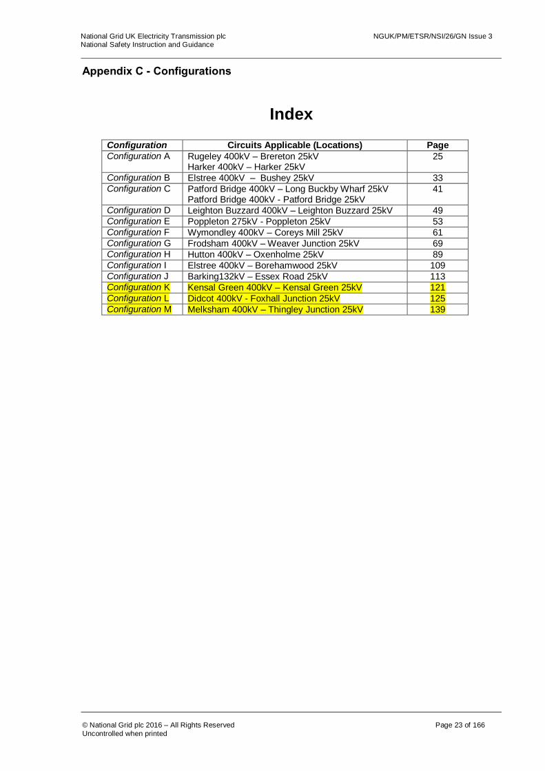
Appendix C - Configurations
Index
Configuration Circuits Applicable (Locations) Page
Configuration A
Rugeley 400kV – Brereton 25kV Harker 400kV – Harker 25kV
25
Configuration B Elstree 400kV – Bushey 25kV 33 Configuration C Patford Bridge 400kV – Long Buckby Wharf 25kV
Patford Bridge 400kV - Patford Bridge 25kV 41
Configuration D Leighton Buzzard 400kV – Leighton Buzzard 25kV 49 Configuration E Poppleton 275kV - Poppleton 25kV 53 Configuration F Wymondley 400kV – Coreys Mill 25kV 61 Configuration G Frodsham 400kV – Weaver Junction 25kV 69 Configuration H Hutton 400kV – Oxenholme 25kV 89 Configuration I Elstree 400kV – Borehamwood 25kV 109 Configuration J Barking132kV – Essex Road 25kV 113 Configuration K Kensal Green 400kV – Kensal Green 25kV 121 Configuration L Didcot 400kV - Foxhall Junction 25kV 125 Configuration M Melksham 400kV – Thingley Junction 25kV 139

National Grid UK Electricity Transmission plc NGUK/PM/ETSR/NSI/26/GN Issue 3 National Safety Instruction and Guidance
© National Grid plc 2016 – All Rights Reserved Page 24 of 166
Uncontrolled when printed
CONFIGURATION A CONFIGURATION A – AREA 1

National Grid UK Electricity Transmission plc NGUK/PM/ETSR/NSI/26/GN Issue 3 National Safety Instruction and Guidance
© National Grid plc 2016 – All Rights Reserved Page 25 of 166
Uncontrolled when printed
The following table is not a switching sequence. A Senior Authorised Person shall include the following tabulated precautions required on Equipment as part of a switching, isolating and earthing sequence to eliminate ACR Current from the designated working AREA. AREA 1 Equipment Precautions Required Reason
Disconnector A Check, open, lock and apply the “Do Not Close Notice”
To prevent any ACR Current from finding a return path through the work area.
National Grid UK Electricity Transmission plc NGUK/PM/ETSR/NSI/26/GN Issue 3 National Safety Instruction and Guidance
© National Grid plc 2016 – All Rights Reserved Page 26 of 166
Uncontrolled when printed
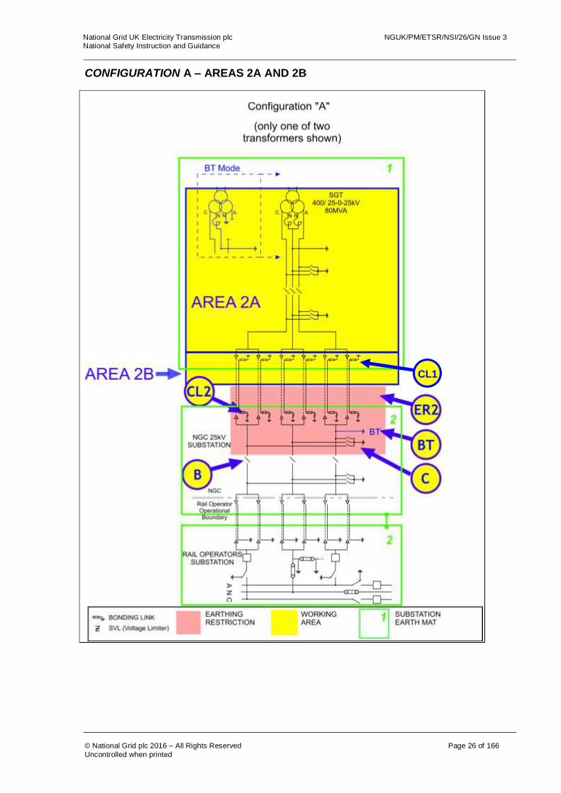
CONFIGURATION A – AREAS 2A AND 2B
CL1

National Grid UK Electricity Transmission plc NGUK/PM/ETSR/NSI/26/GN Issue 3 National Safety Instruction and Guidance
© National Grid plc 2016 – All Rights Reserved Page 27 of 166
Uncontrolled when printed
The following table is not a switching sequence. A Senior Authorised Person shall include the following tabulated precautions required on Equipment as part of a switching, isolating and earthing sequence to eliminate ACR Current from the designated working AREA. AREA 2A Equipment Precautions Required Reason
BT conductor earth, BT. (If Applicable)
Remove conductor earth, apply the “ Do Not Earth Conductors Notice” A Permit will be required for this action.
Action is required to prevent ACR Current flowing along A Pole conductors when an earth is placed on the A Pole conductor in AREA 2A or 2B. Additional precautions may be necessary to avoid the Dangers of induced voltages. This earth must be in place if the circuit is to be energised in permanent BT Mode.
Disconnector B Check, open, lock and apply the “Do Not Close Notice”
Disconnect conductors from 25kV substation and rail operators System to stop ACR Current between earth mats via the poles and Neutral Conductors.
Earth Switch C Open Earth Switch C and apply the “Do Not Earth Conductors Notice”
This precaution is necessary, as an earth on any of the Poles or Neutral Conductor will create a parallel path through which ACR Current will flow.
Earth restriction region ER2
Do not apply earths on Equipment inside regions ER2.
This precaution is necessary, as an earth on any of the Poles, Neutral Conductor or Cable Sheath will create a parallel path through which ACR Current will flow.
AREA 2B If works are required on, or that could infringe a Safety Distance to, the cables, cable sealing ends or cable sheath connections then the following additional requirement to those for AREA 2A applies.
Cable sheath earth links CL2.
Remove cable sheath earth and bonding links Apply the “Do Not Earth Conductors Notice”.
These links are to be removed in case the SVLs are not operating correctly. Removal of the links from all cables will prevent ACR Current flowing between the earth mats along the cable sheaths. NOTE: The cable bonding links “CL1” at the solidly bonded position shall be removed prior to removing / replacing the links “CL2” at an SVL position. “CL1” shall not be quoted as an ACR precaution.
For guidance on the use of AREA 2B or AREA 3 refer to Section 4.3 of this document. For multiple work locations on cables or their accessories refer to section 8.1 of this document.

National Grid UK Electricity Transmission plc NGUK/PM/ETSR/NSI/26/GN Issue 3 National Safety Instruction and Guidance
© National Grid plc 2016 – All Rights Reserved Page 28 of 166
Uncontrolled when printed
CONFIGURATION A – AREA 3

National Grid UK Electricity Transmission plc NGUK/PM/ETSR/NSI/26/GN Issue 3 National Safety Instruction and Guidance
© National Grid plc 2016 – All Rights Reserved Page 29 of 166
Uncontrolled when printed
The following table is not a switching sequence. A Senior Authorised Person shall include the following tabulated precautions required on Equipment as part of a switching, isolating and earthing sequence to eliminate ACR Current from the designated working AREA. AREA 3 Equipment Precautions Required Reason
BT conductor earth, BT. (If Applicable)
Remove conductor earth. Apply the “Do Not Earth Conductors Notice”. A Permit will be required for this action.
This precaution is to prevent ACR Current flowing along A Pole conductors if an earth is placed on the A Pole conductor to the 400kV station mat. Additional precautions may be necessary to avoid the Dangers of induced voltages
Disconnectors A and B
Check, open, lock and apply the “Do Not Close Notice”
Avoid ACR Current in conductors between the 25kV and 400kV substations from the rail operator’s System.
Earth Switches C and D
Open Earth Switches and apply the “ Do Not Earth Conductors Notice”
This precaution is necessary to prevent ACR Current flowing along the cable and through the mass of earth when an earth is placed on a cable conductor or sheath in AREA 3.
Earthing restriction zones ER1 and ER2.
Do not apply earths on Equipment inside regions ER1 or ER2.
This precaution is necessary to prevent ACR Current flowing along the cable and through the mass of earth when an earth is placed on a cable conductor or sheath in AREA 3. The placing of an earth in the restricted regions ER3 or ER4 would create an alternative path for ACR Current(s).
Cable sheath earth links, CL1 and CL2.
Remove cable sheath earth and bonding links Apply the “Do Not Earth Conductors Notice”.
These links are to be removed in case the SVLs are not operating correctly. Removal of the links from all cables will prevent ACR Current flowing between the earth mats along the cable sheaths. The cable bonding links “CL1” at the solidly bonded position shall be removed prior to removing the links “CL2” at an SVL position. This will avoid ACR Current(s) flowing during the application of Earthing Devices.
For guidance on the use of AREA 2B, AREA 4B or AREA 3 refer to Section 4.3 of this document.
For multiple work locations on cables or their accessories refer to section 8.1 of this document.

National Grid UK Electricity Transmission plc NGUK/PM/ETSR/NSI/26/GN Issue 3 National Safety Instruction and Guidance
© National Grid plc 2016 – All Rights Reserved Page 30 of 166
Uncontrolled when printed
CONFIGURATION A – AREA 4A & AREA 4B

National Grid UK Electricity Transmission plc NGUK/PM/ETSR/NSI/26/GN Issue 3 National Safety Instruction and Guidance
© National Grid plc 2016 – All Rights Reserved Page 31 of 166
Uncontrolled when printed
The following table is not a switching sequence. A Senior Authorised Person shall include the following tabulated precautions required on Equipment as part of a switching, isolating and earthing sequence to eliminate ACR Current from the designated working AREA.
AREA 4A
Equipment Precautions Required Reason
Disconnector A Check, open, lock and apply the “Do Not Close Notice”
Disconnect conductors from 25kV substation and rail operators system and stop ACR Current between earth mats, via the pole and Neutral Conductors, find a return path through the transformer earth.
Earth Switch D Open Earth Switch D and apply the “Do Not Earth Conductors Notice”.
This precaution is necessary to prevent ACR Current) flowing along conductors if an earth is placed on a conductor, which would create a parallel path for ACR Current(s).
Earthing restriction zone ER1.
Do not apply earths on Equipment inside region ER1.
This precaution is necessary to prevent ACR Current flowing along conductors if an earth is placed on a conductor, which would create a parallel path for ACR Current(s).
AREA 4B If works are required on, or that may infringe Safety Distance to, the Cables, Cable Sealing Ends or Cable Sheath connections then the following additional requirement to those for AREA 4A applies.
Cable sheath earth links, CL1.
Remove cable sheath bonding links. Apply the “Do Not Earth Conductors Notice”.
These links are to be removed in case the SVLs are not operating correctly. Removal of the links from all cables will prevent ACR Current flowing between the earth mats along the cable sheaths. Additional precautions may be necessary to avoid the Dangers of impressed voltages (NSI 5). The links must be reinstalled before the circuit is energised.
For guidance on the use of AREA 3 or AREA 4B refer to the guidance notes section 4.3. For multiple work locations on cables or their accessories refer to section 8.1 of this document.
National Grid UK Electricity Transmission plc NGUK/PM/ETSR/NSI/26/GN Issue 3 National Safety Instruction and Guidance
© National Grid plc 2016 – All Rights Reserved Page 32 of 166
Uncontrolled when printed
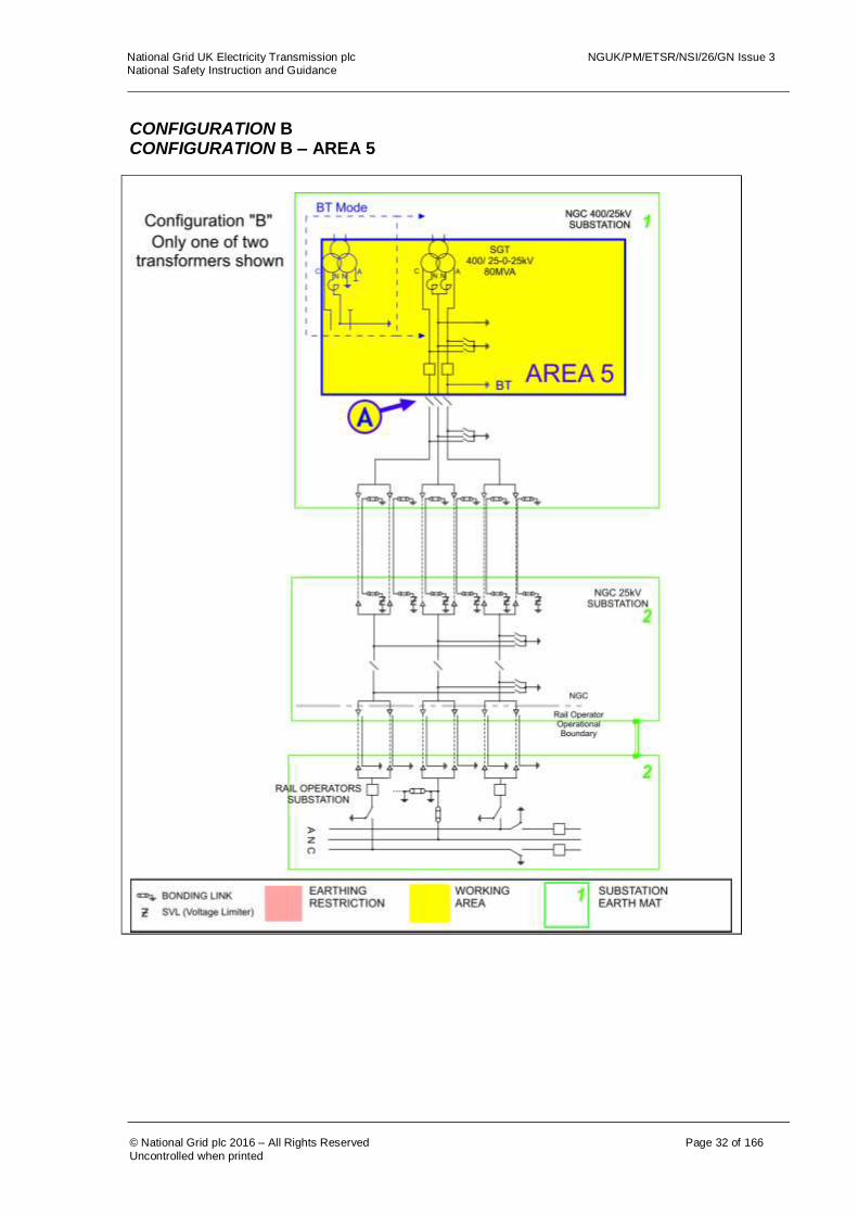
CONFIGURATION B CONFIGURATION B – AREA 5
National Grid UK Electricity Transmission plc NGUK/PM/ETSR/NSI/26/GN Issue 3 National Safety Instruction and Guidance
© National Grid plc 2016 – All Rights Reserved Page 33 of 166
Uncontrolled when printed
The following table is not a switching sequence. A Senior Authorised Person shall include the following tabulated precautions required on Equipment as part of a switching, isolating and earthing sequence to eliminate ACR Current from the designated working AREA. AREA 5 Equipment Precautions Required Reason
Disconnector A Check, open, lock and apply the “Do Not Close Notice”
To prevent any ACR Current from finding a return path through the work area.
National Grid UK Electricity Transmission plc NGUK/PM/ETSR/NSI/26/GN Issue 3 National Safety Instruction and Guidance
© National Grid plc 2016 – All Rights Reserved Page 34 of 166
Uncontrolled when printed
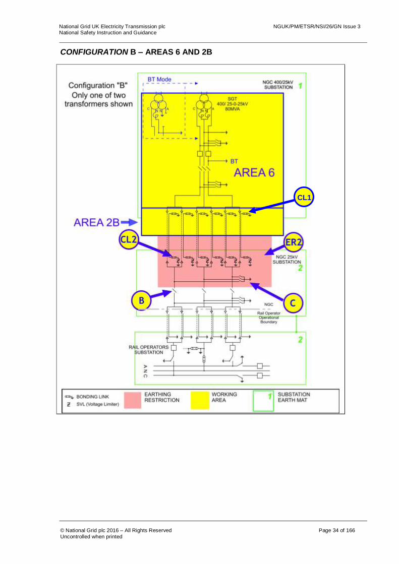
CONFIGURATION B – AREAS 6 AND 2B
CL1
National Grid UK Electricity Transmission plc NGUK/PM/ETSR/NSI/26/GN Issue 3 National Safety Instruction and Guidance
© National Grid plc 2016 – All Rights Reserved Page 35 of 166
Uncontrolled when printed
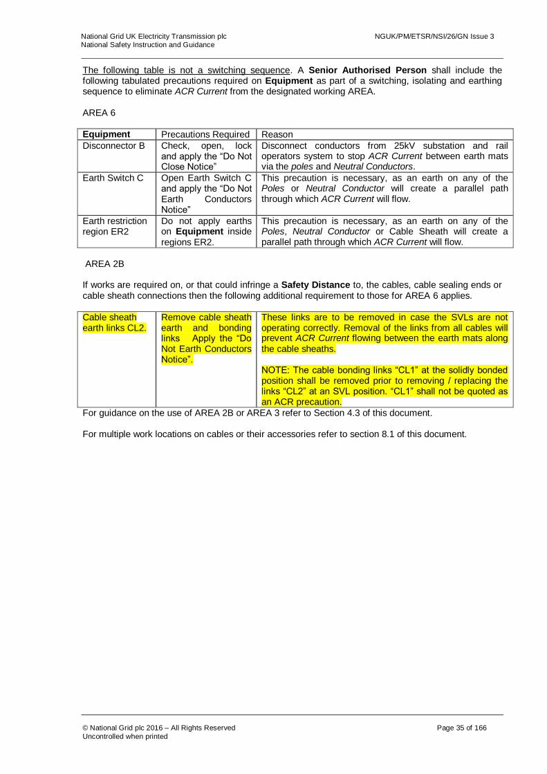
The following table is not a switching sequence. A Senior Authorised Person shall include the following tabulated precautions required on Equipment as part of a switching, isolating and earthing sequence to eliminate ACR Current from the designated working AREA. AREA 6 Equipment Precautions Required Reason
Disconnector B Check, open, lock and apply the “Do Not Close Notice”
Disconnect conductors from 25kV substation and rail operators system to stop ACR Current between earth mats via the poles and Neutral Conductors.
Earth Switch C Open Earth Switch C and apply the “Do Not Earth Conductors Notice”
This precaution is necessary, as an earth on any of the Poles or Neutral Conductor will create a parallel path through which ACR Current will flow.
Earth restriction region ER2
Do not apply earths on Equipment inside regions ER2.
This precaution is necessary, as an earth on any of the Poles, Neutral Conductor or Cable Sheath will create a parallel path through which ACR Current will flow.
AREA 2B If works are required on, or that could infringe a Safety Distance to, the cables, cable sealing ends or cable sheath connections then the following additional requirement to those for AREA 6 applies.
Cable sheath earth links CL2.
Remove cable sheath earth and bonding links Apply the “Do Not Earth Conductors Notice”.
These links are to be removed in case the SVLs are not operating correctly. Removal of the links from all cables will prevent ACR Current flowing between the earth mats along the cable sheaths. NOTE: The cable bonding links “CL1” at the solidly bonded position shall be removed prior to removing / replacing the links “CL2” at an SVL position. “CL1” shall not be quoted as an ACR precaution.
For guidance on the use of AREA 2B or AREA 3 refer to Section 4.3 of this document. For multiple work locations on cables or their accessories refer to section 8.1 of this document.
National Grid UK Electricity Transmission plc NGUK/PM/ETSR/NSI/26/GN Issue 3 National Safety Instruction and Guidance
© National Grid plc 2016 – All Rights Reserved Page 36 of 166
Uncontrolled when printed
CONFIGURATION B – AREA 3
National Grid UK Electricity Transmission plc NGUK/PM/ETSR/NSI/26/GN Issue 3 National Safety Instruction and Guidance
© National Grid plc 2016 – All Rights Reserved Page 37 of 166
Uncontrolled when printed
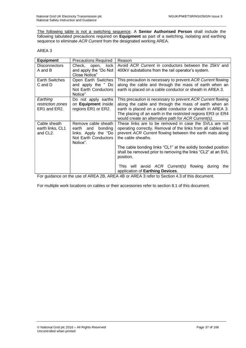
The following table is not a switching sequence. A Senior Authorised Person shall include the following tabulated precautions required on Equipment as part of a switching, isolating and earthing sequence to eliminate ACR Current from the designated working AREA. AREA 3 Equipment Precautions Required Reason
Disconnectors A and B
Check, open, lock and apply the “Do Not Close Notice”
Avoid ACR Current in conductors between the 25kV and 400kV substations from the rail operator’s system.
Earth Switches C and D
Open Earth Switches and apply the “ Do Not Earth Conductors Notice”
This precaution is necessary to prevent ACR Current flowing along the cable and through the mass of earth when an earth is placed on a cable conductor or sheath in AREA 3.
Earthing restriction zones ER1 and ER2.
Do not apply earths on Equipment inside regions ER1 or ER2.
This precaution is necessary to prevent ACR Current flowing along the cable and through the mass of earth when an earth is placed on a cable conductor or sheath in AREA 3. The placing of an earth in the restricted regions ER3 or ER4 would create an alternative path for ACR Current(s).
Cable sheath earth links, CL1 and CL2.
Remove cable sheath earth and bonding links. Apply the “Do Not Earth Conductors Notice”.
These links are to be removed in case the SVLs are not operating correctly. Removal of the links from all cables will prevent ACR Current flowing between the earth mats along the cable sheaths. The cable bonding links “CL1” at the solidly bonded position shall be removed prior to removing the links “CL2” at an SVL position. This will avoid ACR Current(s) flowing during the application of Earthing Devices.
For guidance on the use of AREA 2B, AREA 4B or AREA 3 refer to Section 4.3 of this document. For multiple work locations on cables or their accessories refer to section 8.1 of this document.

National Grid UK Electricity Transmission plc NGUK/PM/ETSR/NSI/26/GN Issue 3 National Safety Instruction and Guidance
© National Grid plc 2016 – All Rights Reserved Page 38 of 166
Uncontrolled when printed
CONFIGURATION B – AREA 4

National Grid UK Electricity Transmission plc NGUK/PM/ETSR/NSI/26/GN Issue 3 National Safety Instruction and Guidance
© National Grid plc 2016 – All Rights Reserved Page 39 of 166
Uncontrolled when printed
The following table is not a switching sequence. A Senior Authorised Person shall include the following tabulated precautions required on Equipment as part of a switching, isolating and earthing sequence to eliminate ACR Current from the designated working AREA.
AREA 4A
Equipment Precautions Required Reason
Disconnector A Check, open, lock and apply the “Do Not Close Notice”
Disconnect conductors from 25kV substation and rail operators system and stop ACR Current between earth mats, via the poles and Neutral Conductors, find a return path through the transformer earth.
Earth Switch D Open Earth Switch D and apply the “Do Not Earth Conductors Notice”.
This precaution is necessary to prevent ACR Current flowing along conductors if an earth is placed on a conductor, which would create a parallel path for ACR Current(s).
Earthing restriction zone ER1.
Do not apply earths on Equipment inside region ER1.
This precaution is necessary to prevent ACR Current flowing along conductors if an earth is placed on a conductor, which would create a parallel path for ACR Current(s).
AREA 4B If works are required on, or that may infringe Safety Distance to, the Cables, Cable Sealing Ends or Cable Sheath connections then the following additional requirement to those for AREA 4A applies.
Cable sheath earth links, CL1.
Remove cable sheath bonding links. Apply the “Do Not Earth Conductors Notice”.
These links are to be removed in case the SVLs are not operating correctly. Removal of the links from all cables will prevent ACR Current flowing between the earth mats along the cable sheaths. Additional precautions may be necessary to avoid the Dangers of impressed voltages (NSI 5). The links must be reinstalled before the circuit is energised.
For guidance on the use of AREA 3 or AREA 4B refer to section 4.3 of this document. For multiple work locations on cables or their accessories refer to section 8.1 of this document.

National Grid UK Electricity Transmission plc NGUK/PM/ETSR/NSI/26/GN Issue 3 National Safety Instruction and Guidance
© National Grid plc 2016 – All Rights Reserved Page 40 of 166
Uncontrolled when printed
CONFIGURATION C CONFIGURATION C – AREA 7

National Grid UK Electricity Transmission plc NGUK/PM/ETSR/NSI/26/GN Issue 3 National Safety Instruction and Guidance
© National Grid plc 2016 – All Rights Reserved Page 41 of 166
Uncontrolled when printed
The following table is not a switching sequence. A Senior Authorised Person shall include the following tabulated precautions required on Equipment as part of a switching, isolating and earthing sequence to eliminate ACR Current from the designated working AREA. AREA 7 Equipment Precautions Required Reason
Disconnector A Check, open, lock and apply the “Do Not Close Notice”.
Avoid ACR Current(s) on conductors from compound 3 and rail operator’s system finding a route through the work area.

National Grid UK Electricity Transmission plc NGUK/PM/ETSR/NSI/26/GN Issue 3 National Safety Instruction and Guidance
© National Grid plc 2016 – All Rights Reserved Page 42 of 166
Uncontrolled when printed
CONFIGURATION C – AREA 8 AND 2B
CL1

National Grid UK Electricity Transmission plc NGUK/PM/ETSR/NSI/26/GN Issue 3 National Safety Instruction and Guidance
© National Grid plc 2016 – All Rights Reserved Page 43 of 166
Uncontrolled when printed
The following table is not a switching sequence. A Senior Authorised Person shall include the following tabulated precautions required on Equipment as part of a switching, isolating and earthing sequence to eliminate ACR Current from the designated working AREA. AREA 8 Equipment Precautions Required Reason
BT conductor earth, BT. (If Applicable)
Remove conductor earth, apply the “ Do Not Earth Conductors Notice” A Permit will be required for this action.
Action is required to prevent ACR Current flowing along A Pole conductors when an earth is placed on the A Pole conductor in AREA 8 or 2B. Additional precautions may be necessary to avoid the Dangers of induced voltages. This earth must be in place if the circuit is to be energised in permanent BT Mode.
Disconnector B Check, open, lock and apply the “Do Not Close Notice”
Disconnect conductors from 25kV substation and rail operators system to stop ACR Current between earth mats via the pole and Neutral Conductors.
Earth Switch C Open Earth Switch C and apply the “Do Not Earth Conductors Notice”
This precaution is necessary, as an earth on any of the Poles or Neutral Conductor will create a parallel path through which ACR Current will flow.
Earth restriction region ER2
Do not apply earths on Equipment inside regions ER2.
This precaution is necessary, as an earth on any of the Poles, Neutral Conductor or Cable Sheath will create a parallel path through which ACR Current will flow.
AREA 2B If works are required on, or that could infringe a Safety Distance to, the cables, cable sealing ends or cable sheath connections then the following additional requirement to those for AREA 8 applies.
Cable sheath earth links CL2.
Remove cable sheath earth and bonding links Apply the “Do Not Earth Conductors Notice”.
These links are to be removed in case the SVLs are not operating correctly. Removal of the links from all cables will prevent ACR Current flowing between the earth mats along the cable sheaths. NOTE: The cable bonding links “CL1” at the solidly bonded position shall be removed prior to removing / replacing the links “CL2” at an SVL position. “CL1” shall not be quoted as an ACR precaution.
For guidance on the use of AREA 2B or AREA 3 refer to section 4.3 of this document. For multiple work locations on cables or their accessories refer to section 8.1 of this document.
National Grid UK Electricity Transmission plc NGUK/PM/ETSR/NSI/26/GN Issue 3 National Safety Instruction and Guidance
© National Grid plc 2016 – All Rights Reserved Page 44 of 166
Uncontrolled when printed
CONFIGURATION C – AREA 3
National Grid UK Electricity Transmission plc NGUK/PM/ETSR/NSI/26/GN Issue 3 National Safety Instruction and Guidance
© National Grid plc 2016 – All Rights Reserved Page 45 of 166
Uncontrolled when printed
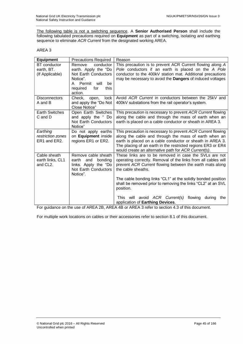
The following table is not a switching sequence. A Senior Authorised Person shall include the following tabulated precautions required on Equipment as part of a switching, isolating and earthing sequence to eliminate ACR Current from the designated working AREA. AREA 3 Equipment Precautions Required Reason
BT conductor earth, BT. (If Applicable)
Remove conductor earth. Apply the “Do Not Earth Conductors Notice”. A Permit will be required for this action.
This precaution is to prevent ACR Current flowing along A Pole conductors if an earth is placed on the A Pole conductor to the 400kV station mat. Additional precautions may be necessary to avoid the Dangers of induced voltages
Disconnectors A and B
Check, open, lock and apply the “Do Not Close Notice”
Avoid ACR Current in conductors between the 25kV and 400kV substations from the rail operator’s system.
Earth Switches C and D
Open Earth Switches and apply the “ Do Not Earth Conductors Notice”
This precaution is necessary to prevent ACR Current flowing along the cable and through the mass of earth when an earth is placed on a cable conductor or sheath in AREA 3.
Earthing restriction zones ER1 and ER2.
Do not apply earths on Equipment inside regions ER1 or ER2.
This precaution is necessary to prevent ACR Current flowing along the cable and through the mass of earth when an earth is placed on a cable conductor or sheath in AREA 3. The placing of an earth in the restricted regions ER3 or ER4 would create an alternative path for ACR Current(s).
Cable sheath earth links, CL1 and CL2.
Remove cable sheath earth and bonding links. Apply the “Do Not Earth Conductors Notice”.
These links are to be removed in case the SVLs are not operating correctly. Removal of the links from all cables will prevent ACR Current flowing between the earth mats along the cable sheaths. The cable bonding links “CL1” at the solidly bonded position shall be removed prior to removing the links “CL2” at an SVL position. This will avoid ACR Current(s) flowing during the application of Earthing Devices.
For guidance on the use of AREA 2B, AREA 4B or AREA 3 refer to section 4.3 of this document. For multiple work locations on cables or their accessories refer to section 8.1 of this document.

National Grid UK Electricity Transmission plc NGUK/PM/ETSR/NSI/26/GN Issue 3 National Safety Instruction and Guidance
© National Grid plc 2016 – All Rights Reserved Page 46 of 166
Uncontrolled when printed
CONFIGURATION C – AREA 4A AND 4B

National Grid UK Electricity Transmission plc NGUK/PM/ETSR/NSI/26/GN Issue 3 National Safety Instruction and Guidance
© National Grid plc 2016 – All Rights Reserved Page 47 of 166
Uncontrolled when printed
The following table is not a switching sequence. A Senior Authorised Person shall include the following tabulated precautions required on Equipment as part of a switching, isolating and earthing sequence to eliminate ACR Current from the designated working AREA. AREA 4A Equipment Precautions Required Reason
Disconnector A Check, open, lock and apply the “Do Not Close Notice”
Disconnect conductors from 25kV substation and rail operators system and stop ACR Current between earth mats, via the pole and Neutral Conductors, find a return path through the transformer earth.
Earth Switch D Open Earth Switch D and apply the “Do Not Earth Conductors Notice”.
This precaution is necessary to prevent ACR Current flowing along conductors if an earth is placed on a conductor, which would create a parallel path for ACR Current(s).
Earthing restriction zone ER1.
Do not apply earths on Equipment inside region ER1.
This precaution is necessary to prevent ACR Current flowing along conductors if an earth is placed on a conductor, which would create a parallel path for ACR Current(s).
AREA 4B If works are required on, or that may infringe Safety Distance to, the Cables, Cable Sealing Ends or Cable Sheath connections then the following additional requirement to those for AREA 4A applies.
Cable sheath earth links, CL1.
Remove cable sheath bonding links. Apply the “Do Not Earth Conductors Notice”.
These links are to be removed in case the SVL’s are not operating correctly. Removal of the links from all cables will prevent ACR Current flowing between the earth mats along the cable sheaths. Additional precautions may be necessary to avoid the Dangers of impressed voltages (NSI 5). The links must be reinstalled before the circuit is energised.
For guidance on the use of AREA 3 or AREA 4B refer to section 4.3 of this document. For multiple work locations on cables or their accessories refer to section 8.1 of this document.

National Grid UK Electricity Transmission plc NGUK/PM/ETSR/NSI/26/GN Issue 3 National Safety Instruction and Guidance
© National Grid plc 2016 – All Rights Reserved Page 48 of 166
Uncontrolled when printed
CONFIGURATION D CONFIGURATION D – AREA 9
National Grid UK Electricity Transmission plc NGUK/PM/ETSR/NSI/26/GN Issue 3 National Safety Instruction and Guidance
© National Grid plc 2016 – All Rights Reserved Page 49 of 166
Uncontrolled when printed
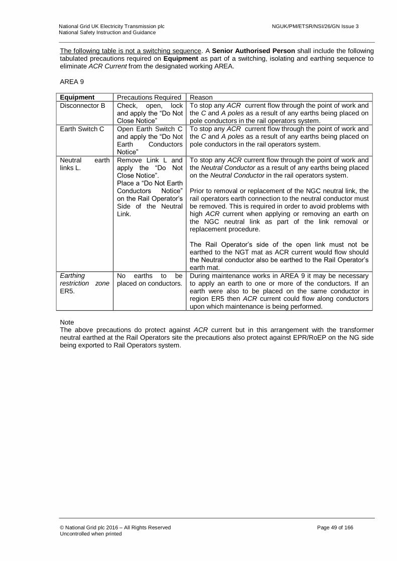
The following table is not a switching sequence. A Senior Authorised Person shall include the following tabulated precautions required on Equipment as part of a switching, isolating and earthing sequence to eliminate ACR Current from the designated working AREA. AREA 9 Equipment Precautions Required Reason
Disconnector B Check, open, lock and apply the “Do Not Close Notice”
To stop any ACR current flow through the point of work and the C and A poles as a result of any earths being placed on pole conductors in the rail operators system.
Earth Switch C Open Earth Switch C and apply the “Do Not Earth Conductors Notice”
To stop any ACR current flow through the point of work and the C and A poles as a result of any earths being placed on pole conductors in the rail operators system.
Neutral earth links L.
Remove Link L and apply the “Do Not Close Notice”. Place a “Do Not Earth Conductors Notice” on the Rail Operator’s Side of the Neutral Link.
To stop any ACR current flow through the point of work and the Neutral Conductor as a result of any earths being placed on the Neutral Conductor in the rail operators system. Prior to removal or replacement of the NGC neutral link, the rail operators earth connection to the neutral conductor must be removed. This is required in order to avoid problems with high ACR current when applying or removing an earth on the NGC neutral link as part of the link removal or replacement procedure. The Rail Operator’s side of the open link must not be earthed to the NGT mat as ACR current would flow should the Neutral conductor also be earthed to the Rail Operator’s earth mat.
Earthing restriction zone ER5.
No earths to be placed on conductors.
During maintenance works in AREA 9 it may be necessary to apply an earth to one or more of the conductors. If an earth were also to be placed on the same conductor in region ER5 then ACR current could flow along conductors upon which maintenance is being performed.
Note The above precautions do protect against ACR current but in this arrangement with the transformer neutral earthed at the Rail Operators site the precautions also protect against EPR/RoEP on the NG side being exported to Rail Operators system.

National Grid UK Electricity Transmission plc NGUK/PM/ETSR/NSI/26/GN Issue 3 National Safety Instruction and Guidance
© National Grid plc 2016 – All Rights Reserved Page 50 of 166
Uncontrolled when printed
CONFIGURATION D – AREA 10
National Grid UK Electricity Transmission plc NGUK/PM/ETSR/NSI/26/GN Issue 3 National Safety Instruction and Guidance
© National Grid plc 2016 – All Rights Reserved Page 51 of 166
Uncontrolled when printed
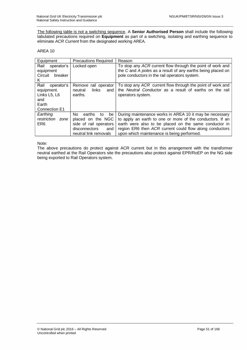
The following table is not a switching sequence. A Senior Authorised Person shall include the following tabulated precautions required on Equipment as part of a switching, isolating and earthing sequence to eliminate ACR Current from the designated working AREA. AREA 10
Equipment Precautions Required Reason
Rail operator’s equipment Circuit breaker K
Locked open To stop any ACR current flow through the point of work and the C and A poles as a result of any earths being placed on pole conductors in the rail operators system.
Rail operator’s equipment. Links L5, L6 and Earth Connection E1
Remove rail operator neutral links and earths.
To stop any ACR current flow through the point of work and the Neutral Conductor as a result of earths on the rail operators system.
Earthing restriction zone ER6
No earths to be placed on the NGC side of rail operators disconnectors and neutral link removals
During maintenance works in AREA 10 it may be necessary to apply an earth to one or more of the conductors. If an earth were also to be placed on the same conductor in region ER6 then ACR current could flow along conductors upon which maintenance is being performed.
Note: The above precautions do protect against ACR current but in this arrangement with the transformer neutral earthed at the Rail Operators site the precautions also protect against EPR/RoEP on the NG side being exported to Rail Operators system.
National Grid UK Electricity Transmission plc NGUK/PM/ETSR/NSI/26/GN Issue 3 National Safety Instruction and Guidance
© National Grid plc 2016 – All Rights Reserved Page 52 of 166
Uncontrolled when printed
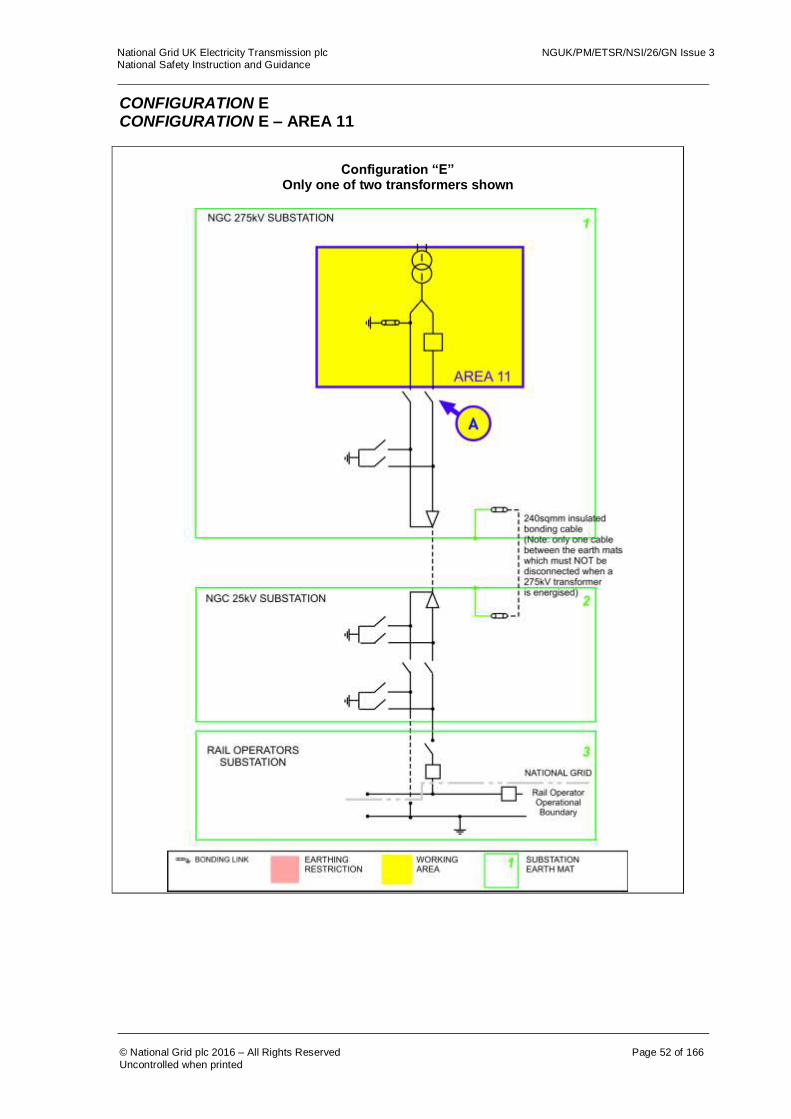
CONFIGURATION E CONFIGURATION E – AREA 11
Configuration “E”
Only one of two transformers shown
National Grid UK Electricity Transmission plc NGUK/PM/ETSR/NSI/26/GN Issue 3 National Safety Instruction and Guidance
© National Grid plc 2016 – All Rights Reserved Page 53 of 166
Uncontrolled when printed
The following table is not a switching sequence. A Senior Authorised Person shall include the following tabulated precautions required on Equipment as part of a switching, isolating and earthing sequence to eliminate ACR Current from the designated working AREA. AREA 11 Equipment Precautions Required Reason
Disconnector A Check, open, lock and apply the “Do Not Close Notice”
To stop any ACR current flow through the point of work and the C and N poles as a result of any earths being placed on pole conductors of system.

National Grid UK Electricity Transmission plc NGUK/PM/ETSR/NSI/26/GN Issue 3 National Safety Instruction and Guidance
© National Grid plc 2016 – All Rights Reserved Page 54 of 166
Uncontrolled when printed
CONFIGURATION E – AREA 12A AND AREA 12B
Configuration “E”
Only one of two transformers shown

National Grid UK Electricity Transmission plc NGUK/PM/ETSR/NSI/26/GN Issue 3 National Safety Instruction and Guidance
© National Grid plc 2016 – All Rights Reserved Page 55 of 166
Uncontrolled when printed
The following table is not a switching sequence. An Senior Authorised Person shall include the following tabulated precautions required on Equipment as part of a switching, isolating and earthing sequence to eliminate ACR Current from the designated working AREA. AREA 12A and AREA 12B
Equipment Precautions Required Reason
Disconnector B Check, open, lock and apply the “Do Not Close Notice”
To stop any ACR current flow through the point of work and the C and N poles as a result of any earths being placed on pole conductors of system.
Earth Switch C Open Earth Switch C and apply the “Do Not Earth Conductors Notice”
To stop any ACR current flowing through the work area.
Earth Switch D Open Earth Switch D and apply the “Do Not Earth Conductors Notice”
To stop any ACR current flowing through the work area or through insulated bonding cable. The closing of this earth switch will create an ACR current path.
Earthing restriction zone ER2
No earths to be placed on any equipment within the earthing restriction zone.
During maintenance works in AREA 12A or AREA 12B it may be necessary to apply an earth to one or more of the conductors. If an earth were also to be placed on the same conductor in region ER2 then ACR current could flow along conductors upon which maintenance is being performed.
AREA 12B ONLY If works are required on, or that may infringe Safety Distance to, the Cables, Cable Sealing Ends or Cable Sheath connections then, in addition to the requirements for AREA 12A, the 25kV power cable sheath and cable joint coverings of the in-service cable shall be confirmed to be intact by testing.
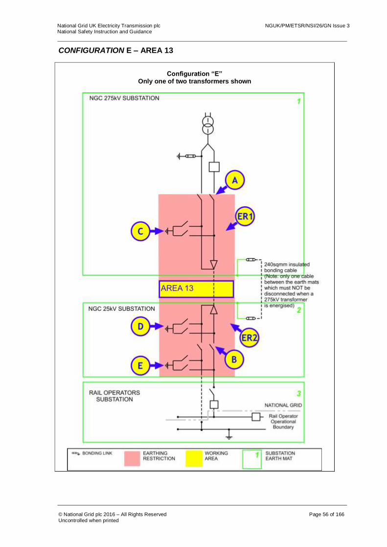
National Grid UK Electricity Transmission plc NGUK/PM/ETSR/NSI/26/GN Issue 3 National Safety Instruction and Guidance
© National Grid plc 2016 – All Rights Reserved Page 56 of 166
Uncontrolled when printed
CONFIGURATION E – AREA 13
Configuration “E”
Only one of two transformers shown

National Grid UK Electricity Transmission plc NGUK/PM/ETSR/NSI/26/GN Issue 3 National Safety Instruction and Guidance
© National Grid plc 2016 – All Rights Reserved Page 57 of 166
Uncontrolled when printed
The following table is not a switching sequence. A Senior Authorised Person shall include the following tabulated precautions required on Equipment as part of a switching, isolating and earthing sequence to eliminate ACR Current from the designated working AREA. AREA 13
Equipment Precautions Required Reason
Disconnector A Check, open, lock and apply the “Do Not Close Notice”
To stop any ACR current flow through the point of work and the C and N poles as a result of any earths being placed on pole conductors of system.
Disconnector B Check, open, lock and apply the “Do Not Close Notice”
To stop any ACR current flow through the point of work and the C and N poles as a result of any earths being placed on pole conductors of system.
Earth Switch C Open Earth Switch C and apply the “Do Not Earth Conductors Notice”
To stop any ACR current flowing through the work area or increased ACR current through insulated bonding cable.
Earth Switch D Open Earth Switch D and apply the “Do Not Earth Conductors Notice”
To stop any ACR current flowing through the work area or through insulated bonding cable. The closing of this earth switch will create an ACR current path.
Earth Switch E Open Earth Switch E and apply the “Do Not Earth Conductors Notice”
To stop any ACR current flowing through the work area or increased ACR current through insulated bonding cable.
Earthing restriction zone ER1
No earths to be placed on any equipment within the earthing restriction zone.
During maintenance works it may be necessary to apply an earth to one or more of the cable conductors. If an earth were also to be placed on the same conductor in region ER1 then ACR current could flow along conductors upon which maintenance is being performed.
Earthing restriction zone ER2
No earths to be placed on any equipment within the earthing restriction zone.
During maintenance works it may be necessary to apply an earth to one or more of the cable conductors. If an earth were also to be placed on the same conductor in region ER2 then ACR current could flow along conductors upon which maintenance is being performed.
For multiple work locations on cables or their accessories refer to section 8.1 of this document.

National Grid UK Electricity Transmission plc NGUK/PM/ETSR/NSI/26/GN Issue 3 National Safety Instruction and Guidance
© National Grid plc 2016 – All Rights Reserved Page 58 of 166
Uncontrolled when printed
CONFIGURATION E – AREA 14
Configuration “E”
Only one of two transformers shown

National Grid UK Electricity Transmission plc NGUK/PM/ETSR/NSI/26/GN Issue 3 National Safety Instruction and Guidance
© National Grid plc 2016 – All Rights Reserved Page 59 of 166
Uncontrolled when printed
The following table is not a switching sequence. A Senior Authorised Person shall include the following tabulated precautions required on Equipment as part of a switching, isolating and earthing sequence to eliminate ACR Current from the designated working AREA. AREA 14
Equipment Precautions Required Reason
Disconnector A Check, open, lock and apply the “Do Not Close Notice”
To stop any ACR current flow through the point of work and the C and N poles as a result of any earths being placed on pole conductors of system.
Disconnector B Check, open, lock and apply the “Do Not Close Notice”
To stop any ACR current flow through the point of work and the C and N poles as a result of any earths being placed on pole conductors of system.
Earth Switch C Open Earth Switch C and apply the “Do Not Earth Conductors Notice”
To stop any ACR current flowing through the work area or increased ACR current through insulated bonding cable.
Earth Switch D Open Earth Switch D and apply the “Do Not Earth Conductors Notice”
To stop any ACR current flowing through the work area or increased ACR current through insulated bonding cable. The closing of this earth switch will create an ACR path.
Earthing restriction zone ER1
No earths to be placed on any equipment within the earthing restriction zone.
During maintenance works it may be necessary to apply an earth to one or more of the conductors. If an earth were also to be placed on the same conductor in region ER1 then ACR current could flow along conductors upon which maintenance is being performed.
Earthing restriction zone ER2
No earths to be placed on any equipment within the earthing restriction zone.
During maintenance works it may be necessary to apply an earth to one or more of the cable conductors. If an earth were also to be placed on the same conductor in region ER2 then ACR current could flow along conductors upon which maintenance is being performed.
Before commencing work in AREA 14 the 25kV power cable sheath and cable joint coverings shall be confirmed to be intact by testing.

National Grid UK Electricity Transmission plc NGUK/PM/ETSR/NSI/26/GN Issue 3 National Safety Instruction and Guidance
© National Grid plc 2016 – All Rights Reserved Page 60 of 166
Uncontrolled when printed
CONFIGURATION F CONFIGURATION F – AREA 5
National Grid UK Electricity Transmission plc NGUK/PM/ETSR/NSI/26/GN Issue 3 National Safety Instruction and Guidance
© National Grid plc 2016 – All Rights Reserved Page 61 of 166
Uncontrolled when printed
The following table is not a switching sequence. A Senior Authorised Person shall include the following tabulated precautions required on Equipment as part of a switching, isolating and earthing sequence to eliminate ACR Current from the designated working AREA. AREA 5 Equipment Precautions
Required Reason
Disconnector A Check open, lock and apply the “Do Not Close Notice”
To prevent any ACR Current from finding a return path through the work area.
WARNING! THE 25KV CABLE SHEATH LINKS SHALL NEVER TO BE REMOVED OR REPLACED WITHOUT A DOUBLE CIRCUIT OUTAGE. The reason for this is that they solidly bond the Coreys Mill earth mat to the Wymondley earth mat providing an earth return path as the Return Conductor is not earthed at Coreys Mill. As a result there is always the possibility of significant ACR Currents flowing through these links.

National Grid UK Electricity Transmission plc NGUK/PM/ETSR/NSI/26/GN Issue 3 National Safety Instruction and Guidance
© National Grid plc 2016 – All Rights Reserved Page 62 of 166
Uncontrolled when printed
CONFIGURATION F – AREAS 12A AND 12B
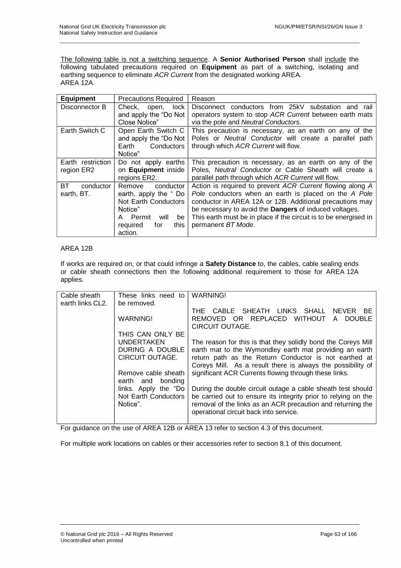
National Grid UK Electricity Transmission plc NGUK/PM/ETSR/NSI/26/GN Issue 3 National Safety Instruction and Guidance
© National Grid plc 2016 – All Rights Reserved Page 63 of 166
Uncontrolled when printed
The following table is not a switching sequence. A Senior Authorised Person shall include the following tabulated precautions required on Equipment as part of a switching, isolating and earthing sequence to eliminate ACR Current from the designated working AREA. AREA 12A Equipment Precautions Required Reason
Disconnector B Check, open, lock and apply the “Do Not Close Notice”
Disconnect conductors from 25kV substation and rail operators system to stop ACR Current between earth mats via the pole and Neutral Conductors.
Earth Switch C Open Earth Switch C and apply the “Do Not Earth Conductors Notice”
This precaution is necessary, as an earth on any of the Poles or Neutral Conductor will create a parallel path through which ACR Current will flow.
Earth restriction region ER2
Do not apply earths on Equipment inside regions ER2.
This precaution is necessary, as an earth on any of the Poles, Neutral Conductor or Cable Sheath will create a parallel path through which ACR Current will flow.
BT conductor earth, BT.
Remove conductor earth, apply the “ Do Not Earth Conductors Notice” A Permit will be required for this action.
Action is required to prevent ACR Current flowing along A Pole conductors when an earth is placed on the A Pole conductor in AREA 12A or 12B. Additional precautions may be necessary to avoid the Dangers of induced voltages. This earth must be in place if the circuit is to be energised in permanent BT Mode.
AREA 12B If works are required on, or that could infringe a Safety Distance to, the cables, cable sealing ends or cable sheath connections then the following additional requirement to those for AREA 12A applies.
Cable sheath earth links CL2.
These links need to be removed. WARNING! THIS CAN ONLY BE UNDERTAKEN DURING A DOUBLE CIRCUIT OUTAGE. Remove cable sheath earth and bonding links. Apply the “Do Not Earth Conductors Notice”.
WARNING! THE CABLE SHEATH LINKS SHALL NEVER BE REMOVED OR REPLACED WITHOUT A DOUBLE CIRCUIT OUTAGE. The reason for this is that they solidly bond the Coreys Mill earth mat to the Wymondley earth mat providing an earth return path as the Return Conductor is not earthed at Coreys Mill. As a result there is always the possibility of significant ACR Currents flowing through these links. During the double circuit outage a cable sheath test should be carried out to ensure its integrity prior to relying on the removal of the links as an ACR precaution and returning the operational circuit back into service.
For guidance on the use of AREA 12B or AREA 13 refer to section 4.3 of this document. For multiple work locations on cables or their accessories refer to section 8.1 of this document.
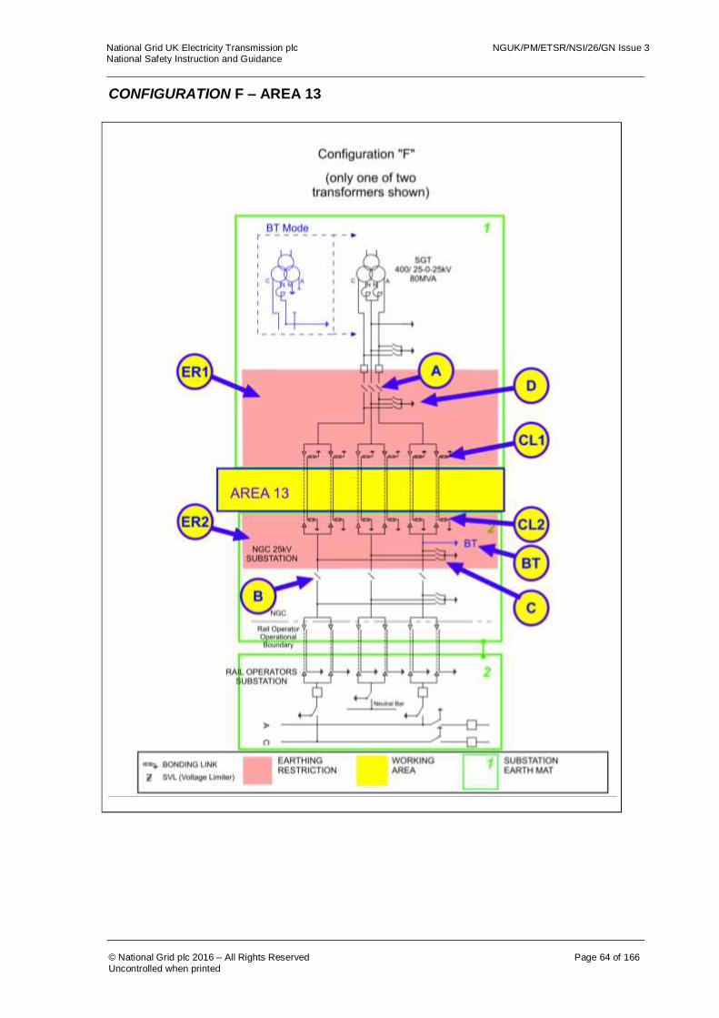
National Grid UK Electricity Transmission plc NGUK/PM/ETSR/NSI/26/GN Issue 3 National Safety Instruction and Guidance
© National Grid plc 2016 – All Rights Reserved Page 64 of 166
Uncontrolled when printed
CONFIGURATION F – AREA 13
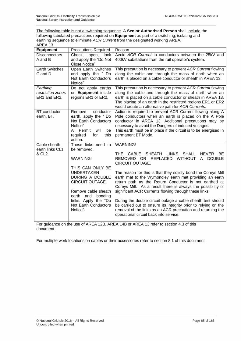
National Grid UK Electricity Transmission plc NGUK/PM/ETSR/NSI/26/GN Issue 3 National Safety Instruction and Guidance
© National Grid plc 2016 – All Rights Reserved Page 65 of 166
Uncontrolled when printed
The following table is not a switching sequence. A Senior Authorised Person shall include the following tabulated precautions required on Equipment as part of a switching, isolating and earthing sequence to eliminate ACR Current from the designated working AREA. AREA 13 Equipment Precautions Required Reason
Disconnectors A and B
Check, open, lock and apply the “Do Not Close Notice”
Avoid ACR Current in conductors between the 25kV and 400kV substations from the rail operator’s system.
Earth Switches C and D
Open Earth Switches and apply the “ Do Not Earth Conductors Notice”
This precaution is necessary to prevent ACR Current flowing along the cable and through the mass of earth when an earth is placed on a cable conductor or sheath in AREA 13.
Earthing restriction zones ER1 and ER2.
Do not apply earths on Equipment inside regions ER1 or ER2.
This precaution is necessary to prevent ACR Current flowing along the cable and through the mass of earth when an earth is placed on a cable conductor or sheath in AREA 13. The placing of an earth in the restricted regions ER1 or ER2 would create an alternative path for ACR Currents.
BT conductor earth, BT.
Remove conductor earth, apply the “ Do Not Earth Conductors Notice” A Permit will be required for this action.
Action is required to prevent ACR Current flowing along A Pole conductors when an earth is placed on the A Pole conductor in AREA 13. Additional precautions may be necessary to avoid the Dangers of induced voltages. This earth must be in place if the circuit is to be energised in permanent BT Mode.
Cable sheath earth links CL1 & CL2.
These links need to be removed. WARNING! THIS CAN ONLY BE UNDERTAKEN DURING A DOUBLE CIRCUIT OUTAGE. Remove cable sheath earth and bonding links. Apply the “Do Not Earth Conductors Notice”.
WARNING! THE CABLE SHEATH LINKS SHALL NEVER BE REMOVED OR REPLACED WITHOUT A DOUBLE CIRCUIT OUTAGE. The reason for this is that they solidly bond the Coreys Mill earth mat to the Wymondley earth mat providing an earth return path as the Return Conductor is not earthed at Coreys Mill. As a result there is always the possibility of significant ACR Currents flowing through these links. During the double circuit outage a cable sheath test should be carried out to ensure its integrity prior to relying on the removal of the links as an ACR precaution and returning the operational circuit back into service.
For guidance on the use of AREA 12B, AREA 14B or AREA 13 refer to section 4.3 of this document.
For multiple work locations on cables or their accessories refer to section 8.1 of this document.

National Grid UK Electricity Transmission plc NGUK/PM/ETSR/NSI/26/GN Issue 3 National Safety Instruction and Guidance
© National Grid plc 2016 – All Rights Reserved Page 66 of 166
Uncontrolled when printed
CONFIGURATION F – AREA 14A AND 14B

National Grid UK Electricity Transmission plc NGUK/PM/ETSR/NSI/26/GN Issue 3 National Safety Instruction and Guidance
© National Grid plc 2016 – All Rights Reserved Page 67 of 166
Uncontrolled when printed
The following table is not a switching sequence. A Senior Authorised Person shall include the following tabulated precautions required on Equipment as part of a switching, isolating and earthing sequence to eliminate ACR Current from the designated working AREA.
AREA 14A
Equipment Precautions Required Reason
Disconnector A Check, open, lock and apply the “Do Not Close Notice”
Disconnect conductors from 25kV substation and rail operators system and stop ACR Current between earth mats, via the pole and Neutral Conductors, find a return path through the transformer earth.
Earth Switch D Open Earth Switch D and apply the “Do Not Earth Conductors Notice”.
This precaution is necessary to prevent return currents flowing along conductors if an earth is placed on a conductor, which would create a parallel path for ACR Currents.
Disconnector F Locked Open This disconnector and associated Circuit Breaker needs to be locked open.
Neutral Isolation Device G
Locked Open This neutral isolation device needs to be locked open.
Earthing restriction zone ER1.
Do not apply earths on Equipment inside region ER1.
This precaution is necessary to prevent return currents flowing along conductors if an earth is placed on a conductor, which would create a parallel path for ACR Currents.
AREA 14B If works are required on, or that may infringe Safety Distance to, the Cables, Cable Sealing Ends or Cable Sheath connections then the following additional requirement to those for AREA 14A applies.
Cable sheath earth links CL1.
These links need to be removed, however. WARNING! THIS CAN ONLY BE UNDERTAKEN DURING A DOUBLE CIRCUIT OUTAGE. Remove cable sheath earth and bonding links. Apply the “Do Not Earth Conductors Notice”.
WARNING! THE CABLE SHEATH LINKS SHALL NEVER BE REMOVED OR REPLACED WITHOUT A DOUBLE CIRCUIT OUTAGE. The reason for this is that they solidly bond the Coreys Mill earth mat to the Wymondley earth mat providing an earth return path as the Return Conductor is not earthed at Coreys Mill. As a result there is always the possibility of significant ACR Currents flowing through these links. During the double circuit outage a cable sheath test should be carried out to ensure its integrity prior to relying on the removal of the links as an ACR precaution and returning the operational circuit back into service.
For guidance on the use of AREA 13 or AREA 14B refer to section 4.3 of this document. For multiple work locations on cables or their accessories refer to section 8.1 of this document.

National Grid UK Electricity Transmission plc NGUK/PM/ETSR/NSI/26/GN Issue 3 National Safety Instruction and Guidance
© National Grid plc 2016 – All Rights Reserved Page 68 of 166
Uncontrolled when printed
CONFIGURATION G CONFIGURATION G – AREA 1
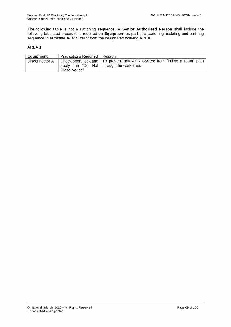
National Grid UK Electricity Transmission plc NGUK/PM/ETSR/NSI/26/GN Issue 3 National Safety Instruction and Guidance
© National Grid plc 2016 – All Rights Reserved Page 69 of 166
Uncontrolled when printed
The following table is not a switching sequence. A Senior Authorised Person shall include the following tabulated precautions required on Equipment as part of a switching, isolating and earthing sequence to eliminate ACR Current from the designated working AREA. AREA 1 Equipment Precautions Required Reason
Disconnector A Check open, lock and apply the “Do Not Close Notice”
To prevent any ACR Current from finding a return path through the work area.
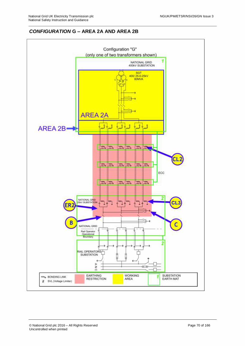
National Grid UK Electricity Transmission plc NGUK/PM/ETSR/NSI/26/GN Issue 3 National Safety Instruction and Guidance
© National Grid plc 2016 – All Rights Reserved Page 70 of 166
Uncontrolled when printed
CONFIGURATION G – AREA 2A AND AREA 2B

National Grid UK Electricity Transmission plc NGUK/PM/ETSR/NSI/26/GN Issue 3 National Safety Instruction and Guidance
© National Grid plc 2016 – All Rights Reserved Page 71 of 166
Uncontrolled when printed
The following table is not a switching sequence. A Senior Authorised Person shall include the following tabulated precautions required on Equipment as part of a switching, isolating and earthing sequence to eliminate ACR Current from the designated working AREA. AREA 2A Equipment Precautions Required Reason
Disconnector B Check open, lock and apply the “Do Not Close Notice”
Disconnect conductors from 25kV substation and rail operators System to stop ACR Current between earth mats via the pole and Neutral Conductors.
Earth Switch C Open Earth Switch C and apply the “Do Not Earth Conductors Notice”
This precaution is necessary, as an earth on any of the Poles or Neutral Conductor will create a parallel path through which ACR Current will flow.
Earth restriction region ER2
Do not apply earths on Equipment inside regions ER2.
This precaution is necessary, as an earth on any of the Poles, Neutral Conductor or Cable Sheath will create a parallel path through which ACR Current will flow.
AREA 2B If works are required on, or that could infringe a Safety Distance to, the cables, cable sealing ends or cable sheath connections then the following additional requirement to those for AREA 2A applies.
Cable sheath bonding links, CL3.
Remove the cable sheath bonding link. Apply the “Do Not Earth Conductors Notice”.
These cable sheath bonding links are removed in case the SVLs on the same cable section are not operating correctly. Removal of the cable sheath bonding links from all cables will prevent ACR Current flowing along the cable sheaths from the 25kV substation earth mat.
Cable sheath bonding links CL2.
Remove the cable sheath earth link in accordance with the principles of NSI 5. Apply the “Do Not Earth Conductors Notice”.
These cable sheath bonding links are removed in case the SVLs are not operating correctly. Removal of the cable sheath bonding links from all cables will prevent ACR Current flowing between the earth mats along the cable sheaths.
For guidance on the use of AREA 2B or AREA 3A refer to section 4.3 of this document.
For multiple work locations on cables or their accessories refer to section 8.1 of this document.

National Grid UK Electricity Transmission plc NGUK/PM/ETSR/NSI/26/GN Issue 3 National Safety Instruction and Guidance
© National Grid plc 2016 – All Rights Reserved Page 72 of 166
Uncontrolled when printed
CONFIGURATION G – AREA 3A
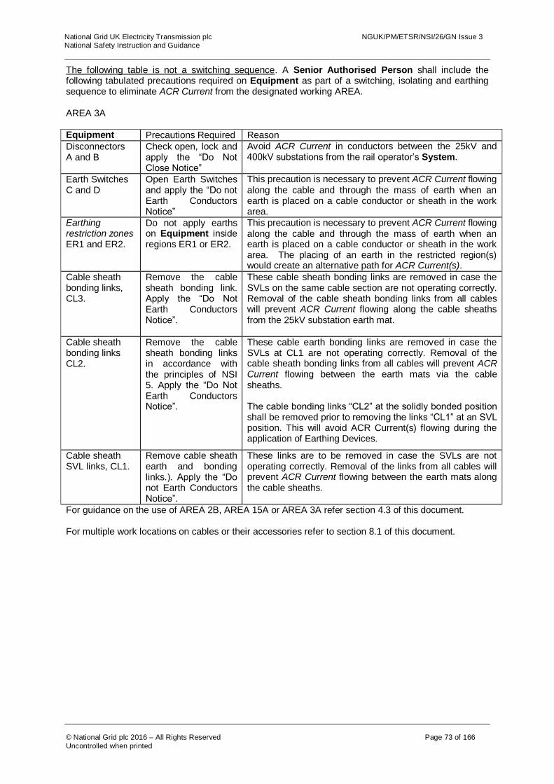
National Grid UK Electricity Transmission plc NGUK/PM/ETSR/NSI/26/GN Issue 3 National Safety Instruction and Guidance
© National Grid plc 2016 – All Rights Reserved Page 73 of 166
Uncontrolled when printed
The following table is not a switching sequence. A Senior Authorised Person shall include the following tabulated precautions required on Equipment as part of a switching, isolating and earthing sequence to eliminate ACR Current from the designated working AREA. AREA 3A Equipment Precautions Required Reason
Disconnectors A and B
Check open, lock and apply the “Do Not Close Notice”
Avoid ACR Current in conductors between the 25kV and 400kV substations from the rail operator’s System.
Earth Switches C and D
Open Earth Switches and apply the “Do not Earth Conductors Notice”
This precaution is necessary to prevent ACR Current flowing along the cable and through the mass of earth when an earth is placed on a cable conductor or sheath in the work area.
Earthing restriction zones ER1 and ER2.
Do not apply earths on Equipment inside regions ER1 or ER2.
This precaution is necessary to prevent ACR Current flowing along the cable and through the mass of earth when an earth is placed on a cable conductor or sheath in the work area. The placing of an earth in the restricted region(s) would create an alternative path for ACR Current(s).
Cable sheath bonding links, CL3.
Remove the cable sheath bonding link. Apply the “Do Not Earth Conductors Notice”.
These cable sheath bonding links are removed in case the SVLs on the same cable section are not operating correctly. Removal of the cable sheath bonding links from all cables will prevent ACR Current flowing along the cable sheaths from the 25kV substation earth mat.
Cable sheath bonding links CL2.
Remove the cable sheath bonding links in accordance with the principles of NSI 5. Apply the “Do Not Earth Conductors Notice”.
These cable earth bonding links are removed in case the SVLs at CL1 are not operating correctly. Removal of the cable sheath bonding links from all cables will prevent ACR Current flowing between the earth mats via the cable sheaths. The cable bonding links “CL2” at the solidly bonded position shall be removed prior to removing the links “CL1” at an SVL position. This will avoid ACR Current(s) flowing during the application of Earthing Devices.
Cable sheath SVL links, CL1.
Remove cable sheath earth and bonding links.). Apply the “Do not Earth Conductors Notice”.
These links are to be removed in case the SVLs are not operating correctly. Removal of the links from all cables will prevent ACR Current flowing between the earth mats along the cable sheaths.
For guidance on the use of AREA 2B, AREA 15A or AREA 3A refer section 4.3 of this document. For multiple work locations on cables or their accessories refer to section 8.1 of this document.

National Grid UK Electricity Transmission plc NGUK/PM/ETSR/NSI/26/GN Issue 3 National Safety Instruction and Guidance
© National Grid plc 2016 – All Rights Reserved Page 74 of 166
Uncontrolled when printed
CONFIGURATION G – AREA 3B

National Grid UK Electricity Transmission plc NGUK/PM/ETSR/NSI/26/GN Issue 3 National Safety Instruction and Guidance
© National Grid plc 2016 – All Rights Reserved Page 75 of 166
Uncontrolled when printed
The following table is not a switching sequence. A Senior Authorised Person shall include the following tabulated precautions required on Equipment as part of a switching, isolating and earthing sequence to eliminate ACR Current from the designated working AREA. AREA 3B Equipment Precautions Required Reason
Disconnectors A and B
Check open, lock and apply the “Do Not Close Notice”
Avoid ACR Current in conductors between the 25kV and 400kV substations from the rail operator’s System.
Earth Switches C and D
Open Earth Switches and apply the “Do not Earth Conductors Notice”
This precaution is necessary to prevent ACR Current flowing along the cable and through the mass of earth when an earth is placed on a cable conductor or sheath in the work area.
Earthing restriction zones ER1 and ER2.
Do not apply earths on Equipment inside regions ER1 or ER2.
This precaution is necessary to prevent ACR Current flowing along the cable and through the mass of earth when an earth is placed on a cable conductor or sheath in the work area. The placing of an earth in the restricted region(s) would create an alternative path for ACR Current(s).
Cable sheath bonding links, CL3.
Remove the cable sheath bonding link. Apply the “Do Not Earth Conductors Notice”.
These cable sheath bonding links are removed in case the SVLs on the same cable section are not operating correctly. Removal of the cable sheath bonding links from all cables will prevent ACR Current flowing along the cable sheaths from the 25kV substation earth mat.
Cable sheath bonding links, CL2.
Remove the sheath links in accordance with the principles of NSI 5. Apply the “Do Not Earth Conductors Notice”.
These links are removed in case the SVLs at CL1 are not operating correctly. Removal of the SVLs from all cables will prevent ACR Current flowing between the earth mats along the cable sheaths. The cable bonding links “CL2” at the solidly bonded position shall be removed prior to removing the links “CL1” at an SVL position. This will avoid ACR Current(s) flowing during the application of Earthing Devices.
Cable SVLs CL1.
Remove the sheath voltage limiter in accordance with the principles of NSI 5. Apply the “Do Not Earth Conductors Notice”.
These SVLs are removed in case the SVLs are not operating correctly. Removal of the SVLs from all cables will prevent ACR Current flowing between the earth mats along the cable sheaths.
For guidance on the use of AREA 15A, AREA 15B or AREA refer to section 4.3 of this document.
For multiple work locations on cables or their accessories refer to section 8.1 of this document.
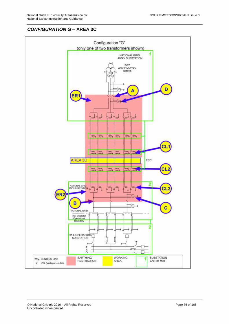
National Grid UK Electricity Transmission plc NGUK/PM/ETSR/NSI/26/GN Issue 3 National Safety Instruction and Guidance
© National Grid plc 2016 – All Rights Reserved Page 76 of 166
Uncontrolled when printed
CONFIGURATION G – AREA 3C
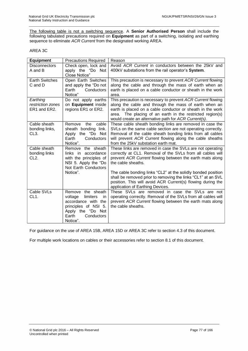
National Grid UK Electricity Transmission plc NGUK/PM/ETSR/NSI/26/GN Issue 3 National Safety Instruction and Guidance
© National Grid plc 2016 – All Rights Reserved Page 77 of 166
Uncontrolled when printed
The following table is not a switching sequence. A Senior Authorised Person shall include the following tabulated precautions required on Equipment as part of a switching, isolating and earthing sequence to eliminate ACR Current from the designated working AREA. AREA 3C Equipment Precautions Required Reason
Disconnectors A and B
Check open, lock and apply the “Do Not Close Notice”
Avoid ACR Current in conductors between the 25kV and 400kV substations from the rail operator’s System.
Earth Switches C and D
Open Earth Switches and apply the “Do not Earth Conductors Notice”
This precaution is necessary to prevent ACR Current flowing along the cable and through the mass of earth when an earth is placed on a cable conductor or sheath in the work area.
Earthing restriction zones ER1 and ER2.
Do not apply earths on Equipment inside regions ER1 or ER2.
This precaution is necessary to prevent ACR Current flowing along the cable and through the mass of earth when an earth is placed on a cable conductor or sheath in the work area. The placing of an earth in the restricted region(s) would create an alternative path for ACR Current(s).
Cable sheath bonding links, CL3.
Remove the cable sheath bonding link. Apply the “Do Not Earth Conductors Notice”.
These cable sheath bonding links are removed in case the SVLs on the same cable section are not operating correctly. Removal of the cable sheath bonding links from all cables will prevent ACR Current flowing along the cable sheaths from the 25kV substation earth mat.
Cable sheath bonding links CL2.
Remove the sheath links in accordance with the principles of NSI 5. Apply the “Do Not Earth Conductors Notice”.
These links are removed in case the SVLs are not operating correctly at CL1. Removal of the SVLs from all cables will prevent ACR Current flowing between the earth mats along the cable sheaths. The cable bonding links “CL2” at the solidly bonded position shall be removed prior to removing the links “CL1” at an SVL position. This will avoid ACR Current(s) flowing during the application of Earthing Devices.
Cable SVLs CL1.
Remove the sheath voltage limiters in accordance with the principles of NSI 5. Apply the “Do Not Earth Conductors Notice”.
These SVLs are removed in case the SVLs are not operating correctly. Removal of the SVLs from all cables will prevent ACR Current flowing between the earth mats along the cable sheaths.
For guidance on the use of AREA 15B, AREA 15D or AREA 3C refer to section 4.3 of this document. For multiple work locations on cables or their accessories refer to section 8.1 of this document.

National Grid UK Electricity Transmission plc NGUK/PM/ETSR/NSI/26/GN Issue 3 National Safety Instruction and Guidance
© National Grid plc 2016 – All Rights Reserved Page 78 of 166
Uncontrolled when printed
CONFIGURATION G – AREA 3D
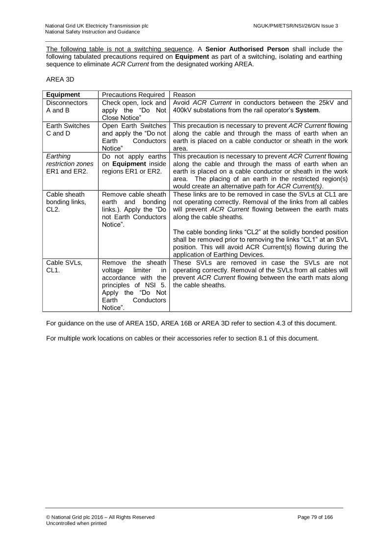
National Grid UK Electricity Transmission plc NGUK/PM/ETSR/NSI/26/GN Issue 3 National Safety Instruction and Guidance
© National Grid plc 2016 – All Rights Reserved Page 79 of 166
Uncontrolled when printed
The following table is not a switching sequence. A Senior Authorised Person shall include the following tabulated precautions required on Equipment as part of a switching, isolating and earthing sequence to eliminate ACR Current from the designated working AREA. AREA 3D Equipment Precautions Required Reason
Disconnectors A and B
Check open, lock and apply the “Do Not Close Notice”
Avoid ACR Current in conductors between the 25kV and 400kV substations from the rail operator’s System.
Earth Switches C and D
Open Earth Switches and apply the “Do not Earth Conductors Notice”
This precaution is necessary to prevent ACR Current flowing along the cable and through the mass of earth when an earth is placed on a cable conductor or sheath in the work area.
Earthing restriction zones ER1 and ER2.
Do not apply earths on Equipment inside regions ER1 or ER2.
This precaution is necessary to prevent ACR Current flowing along the cable and through the mass of earth when an earth is placed on a cable conductor or sheath in the work area. The placing of an earth in the restricted region(s) would create an alternative path for ACR Current(s).
Cable sheath bonding links, CL2.
Remove cable sheath earth and bonding links.). Apply the “Do not Earth Conductors Notice”.
These links are to be removed in case the SVLs at CL1 are not operating correctly. Removal of the links from all cables will prevent ACR Current flowing between the earth mats along the cable sheaths. The cable bonding links “CL2” at the solidly bonded position shall be removed prior to removing the links “CL1” at an SVL position. This will avoid ACR Current(s) flowing during the application of Earthing Devices.
Cable SVLs, CL1.
Remove the sheath voltage limiter in accordance with the principles of NSI 5. Apply the “Do Not Earth Conductors Notice”.
These SVLs are removed in case the SVLs are not operating correctly. Removal of the SVLs from all cables will prevent ACR Current flowing between the earth mats along the cable sheaths.
For guidance on the use of AREA 15D, AREA 16B or AREA 3D refer to section 4.3 of this document. For multiple work locations on cables or their accessories refer to section 8.1 of this document.
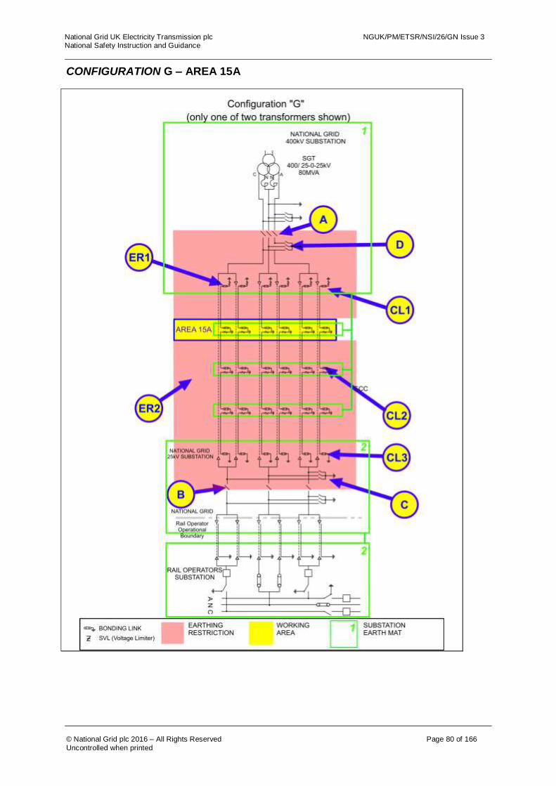
National Grid UK Electricity Transmission plc NGUK/PM/ETSR/NSI/26/GN Issue 3 National Safety Instruction and Guidance
© National Grid plc 2016 – All Rights Reserved Page 80 of 166
Uncontrolled when printed
CONFIGURATION G – AREA 15A

National Grid UK Electricity Transmission plc NGUK/PM/ETSR/NSI/26/GN Issue 3 National Safety Instruction and Guidance
© National Grid plc 2016 – All Rights Reserved Page 81 of 166
Uncontrolled when printed
The following table is not a switching sequence. A Senior Authorised Person shall include the following tabulated precautions required on Equipment as part of a switching, isolating and earthing sequence to eliminate ACR Current from the designated working AREA. AREA 15A Equipment Precautions Required Reason
Disconnectors A and B
Check open, lock and apply the “Do Not Close Notice”
Avoid ACR Current in conductors between the 25kV and 400kV substations from the rail operator’s System.
Earth Switches C and D
Open Earth Switches and apply the “Do not Earth Conductors Notice”
This precaution is necessary to prevent ACR Current flowing along the cable and through the mass of earth when an earth is placed on a cable conductor or sheath in the work area.
Earthing restriction zones ER1 and ER2.
Do not apply earths on Equipment inside regions ER1 or ER2.
This precaution is necessary to prevent ACR Current flowing along the cable and through the mass of earth when an earth is placed on a cable conductor or sheath in the work area. The placing of an earth in the restricted region(s) would create an alternative path for ACR Current(s).
Cable sheath bonding links, CL3.
Remove cable sheath earth and bonding. Apply the “Do not Earth Conductors Notice”.
These cable sheath bonding links are removed in case the SVLs are not operating correctly. Removal of the cable sheath bonding links from all cables will prevent ACR Current flowing along the cable sheaths from the 25kV substation earth mat.
Cable sheath bonding links CL2.
Remove the cable sheath bonding links in accordance with the principles of NSI 5. Apply the “Do Not Earth Conductors Notice”.
These cable sheath bonding links are removed in case the SVLs at CL1 are not operating correctly. Removal of the cable sheath bonding links from all cables will prevent ACR Current flowing between the earth mats along the cable sheaths. The cable bonding links “CL2” at the solidly bonded position shall be removed prior to removing the links “CL1” at an SVL position. This will avoid ACR Current(s) flowing during the application of Earthing Devices.
Cable sheath SVL links CL1.
Remove cable sheath earth and bonding links. Apply the “Do not Earth Conductors Notice”.
These links are to be removed in case the SVLs are not operating correctly. Removal of the links from all cables will prevent ACR Current flowing between the earth mats along the cable sheaths.
For guidance on the use of AREA 15A, AREA 3A or AREA 3B refer to section 4.3 of this document. For multiple work locations on cables or their accessories refer to section 8.1 of this document.
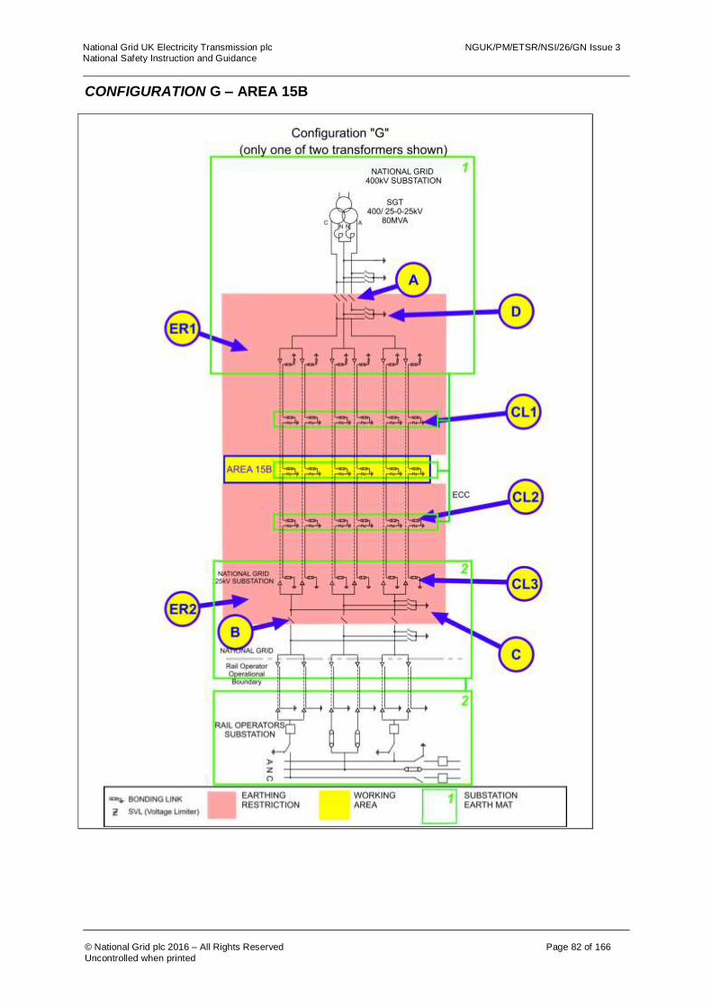
National Grid UK Electricity Transmission plc NGUK/PM/ETSR/NSI/26/GN Issue 3 National Safety Instruction and Guidance
© National Grid plc 2016 – All Rights Reserved Page 82 of 166
Uncontrolled when printed
CONFIGURATION G – AREA 15B

National Grid UK Electricity Transmission plc NGUK/PM/ETSR/NSI/26/GN Issue 3 National Safety Instruction and Guidance
© National Grid plc 2016 – All Rights Reserved Page 83 of 166
Uncontrolled when printed
The following table is not a switching sequence. A Senior Authorised Person shall include the following tabulated precautions required on Equipment as part of a switching, isolating and earthing sequence to eliminate ACR Current from the designated working AREA. AREA 15B Equipment Precautions Required Reason
Disconnectors A and B
Check open, lock and apply the “Do Not Close Notice”
Avoid ACR Current in conductors between the 25kV and 400kV substations from the rail operator’s System.
Earth Switches C and D
Open Earth Switches and apply the “Do not Earth Conductors Notice”
This precaution is necessary to prevent ACR Current flowing along the cable and through the mass of earth when an earth is placed on a cable conductor or sheath in the work area.
Earthing restriction zones ER1 and ER2.
Do not apply earths on Equipment inside regions ER1 or ER2.
This precaution is necessary to prevent ACR Current flowing along the cable and through the mass of earth when an earth is placed on a cable conductor or sheath in the work area. The placing of an earth in the restricted region(s) would create an alternative path for ACR Current(s).
Cable sheath bonding links, CL3.
Remove the cable sheath bonding link. Apply the “Do Not Earth Conductors Notice”.
These cable sheath bonding links are removed in case the SVLs on the same cable section are not operating correctly. Removal of the cable sheath bonding links from all cables will prevent ACR Current flowing along the cable sheaths from the 25kV substation earth mat.
Cable sheath bonding links, CL2.
Remove the sheath links in accordance with the principles of NSI 5. Apply the “Do Not Earth Conductors Notice”.
These links are removed in case the SVLs at CL1 are not operating correctly. Removal of the SVLs from all cables will prevent ACR Current flowing between the earth mats along the cable sheaths. The cable bonding links “CL2” at the solidly bonded position shall be removed prior to removing the links “CL1” at an SVL position. This will avoid ACR Current(s) flowing during the application of Earthing Devices.
Cable SVLs CL1.
Remove the sheath voltage limiter in accordance with the principles of NSI 5. Apply the “Do Not Earth Conductors Notice”.
These SVLs are removed in case the SVLs are not operating correctly. Removal of the SVLs from all cables will prevent ACR Current flowing between the earth mats along the cable sheaths.
For guidance on the use of AREA 15B, AREA 3B or AREA 3C refer to section 4.3 of this document. For multiple work locations on cables or their accessories refer to section 8.1 of this document.

National Grid UK Electricity Transmission plc NGUK/PM/ETSR/NSI/26/GN Issue 3 National Safety Instruction and Guidance
© National Grid plc 2016 – All Rights Reserved Page 84 of 166
Uncontrolled when printed
CONFIGURATION G – AREA 15C

National Grid UK Electricity Transmission plc NGUK/PM/ETSR/NSI/26/GN Issue 3 National Safety Instruction and Guidance
© National Grid plc 2016 – All Rights Reserved Page 85 of 166
Uncontrolled when printed
The following table is not a switching sequence. A Senior Authorised Person shall include the following tabulated precautions required on Equipment as part of a switching, isolating and earthing sequence to eliminate ACR Current from the designated working AREA. AREA 15C Equipment Precautions Required Reason
Disconnectors A and B
Check open, lock and apply the “Do Not Close Notice”
Avoid ACR Current in conductors between the 25kV and 400kV substations from the rail operator’s System.
Earth Switches C and D
Open Earth Switches and apply the “Do not Earth Conductors Notice”
This precaution is necessary to prevent ACR Current flowing along the cable and through the mass of earth when an earth is placed on a cable conductor or sheath in the work area.
Earthing restriction zones ER1 and ER2.
Do not apply earths on Equipment inside regions ER1 or ER2.
This precaution is necessary to prevent ACR Current flowing along the cable and through the mass of earth when an earth is placed on a cable conductor or sheath in the work area. The placing of an earth in the restricted region(s) would create an alternative path for ACR Current(s).
Cable sheath bonding links, CL2.
Remove cable sheath earth and bonding links. Apply the “Do not Earth Conductors Notice”.
These links are to be removed in case the SVLs are not operating correctly. Removal of the links from all cables will prevent ACR Current flowing between the earth mats along the cable sheaths. The cable bonding links “CL2” at the solidly bonded position shall be removed prior to removing the links “CL1” at an SVL position. This will avoid ACR Current(s) flowing during the application of Earthing Devices.
Cable SVLs at, CL1.
Remove the sheath voltage limiter in accordance with the principles of NSI 5. Apply the “Do Not Earth Conductors Notice”.
These SVLs are removed in case the SVLs are not operating correctly. Removal of the SVLs from all cables will prevent ACR Current flowing between the earth mats along the cable sheaths.
For guidance on the use of AREA 15C, AREA 3C or AREA 3D refer to section 4.3 of this document. For multiple work locations on cables or their accessories refer to section 8.1 of this document.

National Grid UK Electricity Transmission plc NGUK/PM/ETSR/NSI/26/GN Issue 3 National Safety Instruction and Guidance
© National Grid plc 2016 – All Rights Reserved Page 86 of 166
Uncontrolled when printed
CONFIGURATION G – AREA 16A AND AREA 16B
CL3

National Grid UK Electricity Transmission plc NGUK/PM/ETSR/NSI/26/GN Issue 3 National Safety Instruction and Guidance
© National Grid plc 2016 – All Rights Reserved Page 87 of 166
Uncontrolled when printed
The following table is not a switching sequence. A Senior Authorised Person shall include the following tabulated precautions required on Equipment as part of a switching, isolating and earthing sequence to eliminate ACR Current from the designated working AREA. AREA 16A Equipment Precautions Required Reason
Disconnector A Check open, lock and apply the “Do Not Close Notice”
Disconnect conductors from 25kV substation and rail operators system and stop ACR Current between earth mats, via the pole and Neutral Conductors, find a return path through the transformer earth.
Earth Switch D Open Earth Switch D and apply the “Do Not Earth Conductors Notice”.
This precaution is necessary to prevent ACR Current flowing along conductors if an earth is placed on a conductor, which would create a parallel path for ACR Current(s).
Earthing restriction zone ER1.
Do not apply earths on Equipment inside region ER1.
This precaution is necessary to prevent ACR Current flowing along conductors if an earth is placed on a conductor, which would create a parallel path for ACR Current(s).
AREA 16B If works are required on, or that may infringe Safety Distance to, the Cables, Cable Sealing Ends or Cable Sheath connections then the following additional requirement to those for AREA 16A applies.
Cable sheath voltage limiters (SVLs) CL1.
Remove the sheath voltage limiter in accordance with the principles of NSI 5. Apply the “Do Not Earth Conductors Notice”.
These SVLs are to be removed in case the SVLs are not operating correctly. Removal of the SVLs from all cables will prevent ACR Current flowing between the earth mats along the cable sheaths. NOTE: The cable bonding links “CL3” at the solidly bonded position shall be removed prior to removing / replacing the links “CL1” at an SVL position. “CL3” shall not be quoted as an ACR precaution.
For guidance on the use of AREA 16B or AREA 3D refer to section 4.3 of this document. For multiple work locations on cables or their accessories refer to section 8.1 of this document.
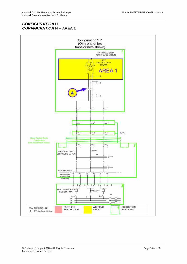
National Grid UK Electricity Transmission plc NGUK/PM/ETSR/NSI/26/GN Issue 3 National Safety Instruction and Guidance
© National Grid plc 2016 – All Rights Reserved Page 88 of 166
Uncontrolled when printed
CONFIGURATION H CONFIGURATION H – AREA 1

National Grid UK Electricity Transmission plc NGUK/PM/ETSR/NSI/26/GN Issue 3 National Safety Instruction and Guidance
© National Grid plc 2016 – All Rights Reserved Page 89 of 166
Uncontrolled when printed
The following table is not a switching sequence. A Senior Authorised Person shall include the following tabulated precautions required on Equipment as part of a switching, isolating and earthing sequence to eliminate ACR Current from the designated working AREA. . AREA 1 Equipment Precautions Required Reason
Disconnector A Check open, lock and apply the “Do Not Close Notice”
To prevent any ACR Current from finding a return path through the work area.
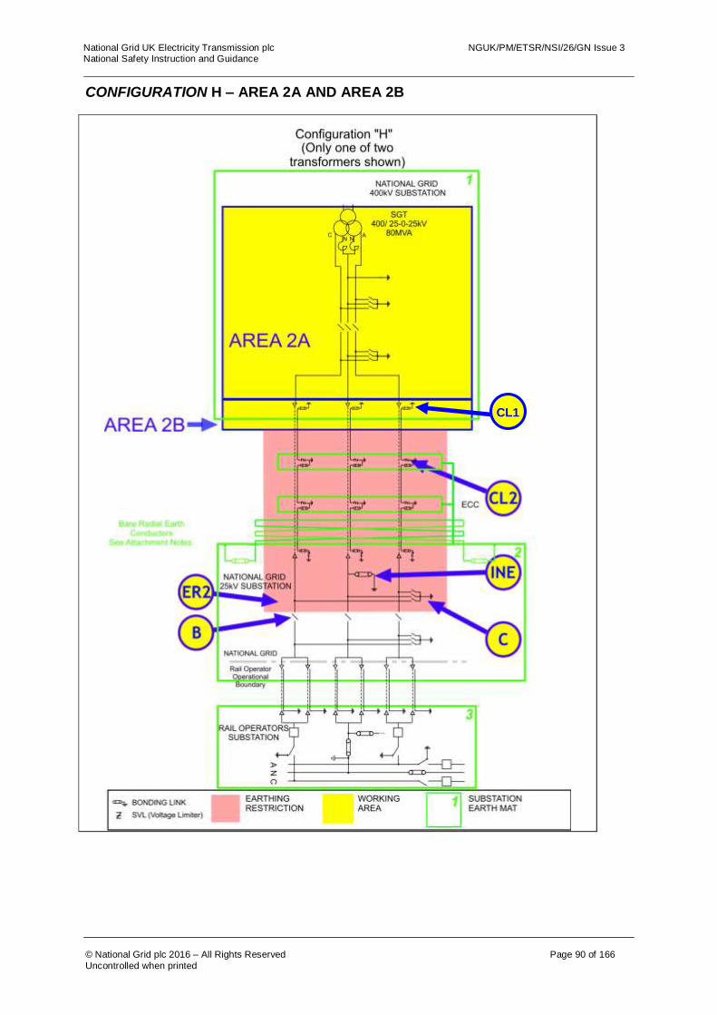
National Grid UK Electricity Transmission plc NGUK/PM/ETSR/NSI/26/GN Issue 3 National Safety Instruction and Guidance
© National Grid plc 2016 – All Rights Reserved Page 90 of 166
Uncontrolled when printed
CONFIGURATION H – AREA 2A AND AREA 2B
CL1

National Grid UK Electricity Transmission plc NGUK/PM/ETSR/NSI/26/GN Issue 3 National Safety Instruction and Guidance
© National Grid plc 2016 – All Rights Reserved Page 91 of 166
Uncontrolled when printed
The following table is not a switching sequence. A Senior Authorised Person shall include the following tabulated precautions required on Equipment as part of a switching, isolating and earthing sequence to eliminate ACR Current from the designated working AREA. AREA 2A Equipment Precautions Required Reason
Disconnector B Check open, lock and apply the “Do Not Close Notice”
Disconnect conductors from 25kV substation and rail operators System to stop ACR Current between earth mats via the pole and Neutral Conductors.
Intermediate Neutral Earth Link, INE
Remove earth link in accordance to the principles of Section 6 and apply the “Do Not Earth Conductors Notice”.
This precaution is necessary to prevent ACR Current flowing along the Neutral Conductor when an earth is placed on the Neutral Conductor in the work area. (Earth Switch C should be closed during this operation)
Earth Switch C Open Earth Switch C and apply the “Do Not Earth Conductors Notice”
This precaution is necessary, as an earth on any of the Poles or Neutral Conductor will create a parallel path through which ACR Current will flow.
Earth restriction region ER2
Do not apply earths on Equipment inside regions ER2.
This precaution is necessary, as an earth on any of the Poles, Neutral Conductor or Cable Sheath will create a parallel path through which ACR Current will flow.
AREA 2B If works are required on, or that could infringe a Safety Distance to, the cables, cable sealing ends or cable sheath connections then the following additional requirement to those for AREA 2A applies.
Cable sheath bonding links (SVL’s) CL2.
Remove the sheath voltage limiter in accordance with the principles of NSI 5. Apply the “Do Not Earth Conductors Notice”.
Removal of the sheath voltage limiters will prevent ACR Current flowing between the earth mats along the cable sheaths. NOTE: The cable bonding links “CL1” at the solidly bonded position shall be removed prior to removing / replacing the links “CL2” at an SVL position. “CL1” shall not be quoted as an ACR precaution.
For guidance on the use of AREA 2B refer to section 4.3 of this document. For multiple work locations on cables or their accessories refer to section 8.1 of this document.

National Grid UK Electricity Transmission plc NGUK/PM/ETSR/NSI/26/GN Issue 3 National Safety Instruction and Guidance
© National Grid plc 2016 – All Rights Reserved Page 92 of 166
Uncontrolled when printed
CONFIGURATION H – AREA 3E

National Grid UK Electricity Transmission plc NGUK/PM/ETSR/NSI/26/GN Issue 3 National Safety Instruction and Guidance
© National Grid plc 2016 – All Rights Reserved Page 93 of 166
Uncontrolled when printed
The following table is not a switching sequence. A Senior Authorised Person shall include the following tabulated precautions required on Equipment as part of a switching, isolating and earthing sequence to eliminate ACR Current from the designated working AREA. AREA 3E Equipment Precautions Required Reason
Disconnectors A and B
Check open, lock and apply the “Do Not Close Notice”
Avoid ACR Current in conductors between the 25kV and 400kV substations from the rail operator’s System.
Intermediate Neutral Earth Link, INE
Remove earth link in accordance to the principles of Section 6 and apply the “Do Not Earth Conductors Notice”.
This precaution is necessary to prevent ACR Current flowing along the Neutral Conductor when an earth is placed on the Neutral Conductor in the work area. (Earth Switch C should be closed during this operation)
Earth Switches C and D
Open Earth Switches and apply the “Do not Earth Conductors Notice”
This precaution is necessary to prevent ACR Current flowing along the cable and through the mass of earth when an earth is placed on a cable conductor or sheath in the work area.
Earthing restriction zones ER1 and ER2.
Do not apply earths on Equipment inside regions ER1 or ER2.
This precaution is necessary to prevent ACR Current flowing along the cable and through the mass of earth when an earth is placed on a cable conductor or sheath in the work area. The placing of an earth in the restricted region(s) would create an alternative path for ACR Current(s).
Cable sheath bonding links CL1.
Remove cable sheath earth and bonding links Apply the “Do not Earth Conductors Notice”.
These cable earth bonding links are removed in case the SVLs at CL2 are not operating correctly. Removal of the cable sheath bonding links from all cables will prevent ACR Current flowing between the earth mats via the cable sheaths. The cable bonding links “CL1” at the solidly bonded position shall be removed prior to removing the links “CL2” at an SVL position. This will avoid ACR Current(s) flowing during the application of Earthing Devices.
Cable sheath SVLs, CL2.
Remove the cable sheath voltage limiters in accordance with the principles of NSI 5. Apply the “Do Not Earth Conductors Notice”.
Removal of the SVLs from all cables will prevent ACR Current flowing between the earth mats along the cable sheaths.
For guidance on the use of AREA 3E refer to section 4.3 of this document. For multiple work locations on cables or their accessories refer to section 8.1 of this document. For work on the cable circuit ECC see the notes for arrangement H at the end of this section.

National Grid UK Electricity Transmission plc NGUK/PM/ETSR/NSI/26/GN Issue 3 National Safety Instruction and Guidance
© National Grid plc 2016 – All Rights Reserved Page 94 of 166
Uncontrolled when printed
CONFIGURATION H – AREA 3F

National Grid UK Electricity Transmission plc NGUK/PM/ETSR/NSI/26/GN Issue 3 National Safety Instruction and Guidance
© National Grid plc 2016 – All Rights Reserved Page 95 of 166
Uncontrolled when printed
The following table is not a switching sequence. A Senior Authorised Person shall include the following tabulated precautions required on Equipment as part of a switching, isolating and earthing sequence to eliminate ACR Current from the designated working AREA. AREA 3F
Equipment Precautions Required Reason
Disconnectors A and B
Check open, lock and apply the “Do Not Close Notice”
Avoid ACR Current in conductors between the 25kV and 400kV substations from the rail operator’s System.
Intermediate Neutral Earth Link, INE
Remove earth link in accordance to the principles of Section 6 and apply the “Do Not Earth Conductors Notice”.
This precaution is necessary to prevent ACR Current flowing along the Neutral Conductor when an earth is placed on the Neutral Conductor in the work area. (Earth Switch C should be closed during this operation)
Earth Switches C and D
Open Earth Switches and apply the “Do not Earth Conductors Notice”
This precaution is necessary to prevent ACR Current flowing along the cable and through the mass of earth when an earth is placed on a cable conductor or sheath in the work area.
Earthing restriction zones ER1 and ER2.
Do not apply earths on Equipment inside regions ER1 or ER2.
This precaution is necessary to prevent ACR Current flowing along the cable and through the mass of earth when an earth is placed on a cable conductor or sheath in the work area. The placing of an earth in the restricted region(s) would create an alternative path for ACR Current(s).
Cable sheath bonding links, CL1.
Remove the cable sheath bonding link. Apply the “Do Not Earth Conductors Notice”.
These cable sheath bonding links are removed in case the SVLs on the same cable section are not operating correctly. Removal of the cable sheath bonding links from all cables will prevent ACR Current flowing along the cable sheaths to the 400kV substation earth mat. The cable bonding links “CL1” at the solidly bonded position shall be removed prior to removing the links “CL2” at an SVL position. This will avoid ACR Current(s) flowing during the application of Earthing Devices.
Cable sheath bonding links, CL2.
Remove the sheath links in accordance with the principles of NSI 5. Apply the “Do Not Earth Conductors Notice”.
These links are removed to prevent ACR Current flowing between the earth mats along the cable sheaths.
Cable SVL’s, CL3.
Remove the sheath voltage limiter in accordance with the principles of NSI 5. Apply the “Do Not Earth Conductors Notice”.
These SVLs are removed in case the SVLs are not operating correctly. Removal of the SVLs from all cables will prevent ACR Current flowing between the earth mats along the cable sheaths.
For guidance on the use of AREA 3F refer to section 4.3 of this document. For multiple work locations on cables or their accessories refer to section 8.1 of this document. For work on the cable circuit Earth ECC see the notes for arrangement H at the end of this section.

National Grid UK Electricity Transmission plc NGUK/PM/ETSR/NSI/26/GN Issue 3 National Safety Instruction and Guidance
© National Grid plc 2016 – All Rights Reserved Page 96 of 166
Uncontrolled when printed
CONFIGURATION H – AREA 3G
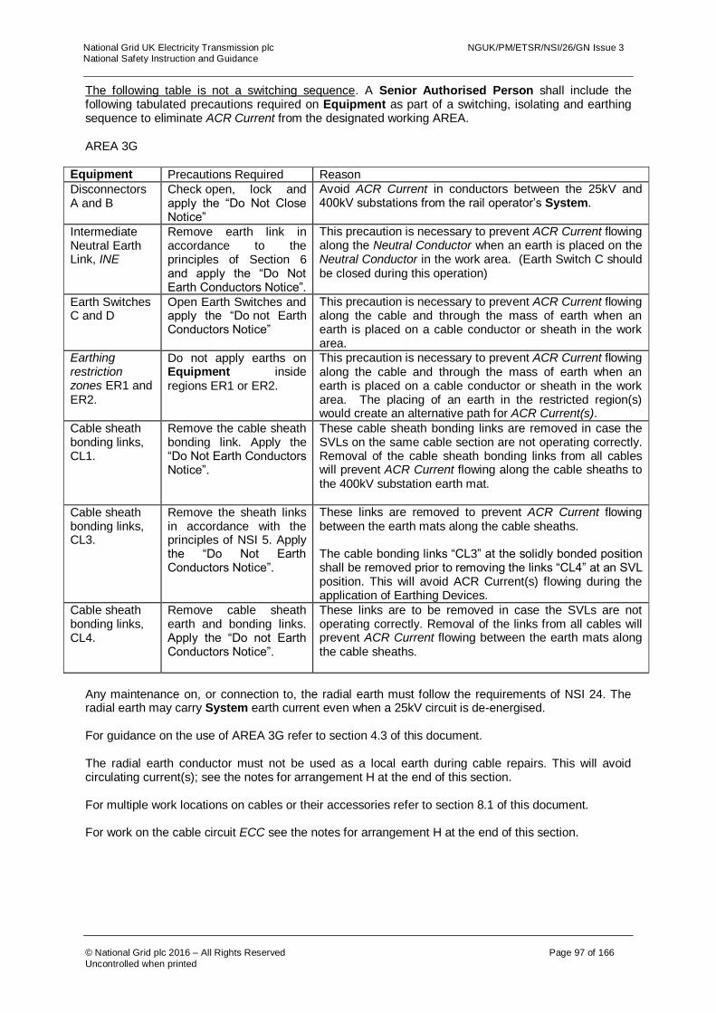
National Grid UK Electricity Transmission plc NGUK/PM/ETSR/NSI/26/GN Issue 3 National Safety Instruction and Guidance
© National Grid plc 2016 – All Rights Reserved Page 97 of 166
Uncontrolled when printed
The following table is not a switching sequence. A Senior Authorised Person shall include the following tabulated precautions required on Equipment as part of a switching, isolating and earthing sequence to eliminate ACR Current from the designated working AREA. AREA 3G
Equipment Precautions Required Reason
Disconnectors A and B
Check open, lock and apply the “Do Not Close Notice”
Avoid ACR Current in conductors between the 25kV and 400kV substations from the rail operator’s System.
Intermediate Neutral Earth Link, INE
Remove earth link in accordance to the principles of Section 6 and apply the “Do Not Earth Conductors Notice”.
This precaution is necessary to prevent ACR Current flowing along the Neutral Conductor when an earth is placed on the Neutral Conductor in the work area. (Earth Switch C should be closed during this operation)
Earth Switches C and D
Open Earth Switches and apply the “Do not Earth Conductors Notice”
This precaution is necessary to prevent ACR Current flowing along the cable and through the mass of earth when an earth is placed on a cable conductor or sheath in the work area.
Earthing restriction zones ER1 and ER2.
Do not apply earths on Equipment inside regions ER1 or ER2.
This precaution is necessary to prevent ACR Current flowing along the cable and through the mass of earth when an earth is placed on a cable conductor or sheath in the work area. The placing of an earth in the restricted region(s) would create an alternative path for ACR Current(s).
Cable sheath bonding links, CL1.
Remove the cable sheath bonding link. Apply the “Do Not Earth Conductors Notice”.
These cable sheath bonding links are removed in case the SVLs on the same cable section are not operating correctly. Removal of the cable sheath bonding links from all cables will prevent ACR Current flowing along the cable sheaths to the 400kV substation earth mat.
Cable sheath bonding links, CL3.
Remove the sheath links in accordance with the principles of NSI 5. Apply the “Do Not Earth Conductors Notice”.
These links are removed to prevent ACR Current flowing between the earth mats along the cable sheaths. The cable bonding links “CL3” at the solidly bonded position shall be removed prior to removing the links “CL4” at an SVL position. This will avoid ACR Current(s) flowing during the application of Earthing Devices.
Cable sheath bonding links, CL4.
Remove cable sheath earth and bonding links. Apply the “Do not Earth Conductors Notice”.
These links are to be removed in case the SVLs are not operating correctly. Removal of the links from all cables will prevent ACR Current flowing between the earth mats along the cable sheaths.
Any maintenance on, or connection to, the radial earth must follow the requirements of NSI 24. The radial earth may carry System earth current even when a 25kV circuit is de-energised. For guidance on the use of AREA 3G refer to section 4.3 of this document. The radial earth conductor must not be used as a local earth during cable repairs. This will avoid circulating current(s); see the notes for arrangement H at the end of this section. For multiple work locations on cables or their accessories refer to section 8.1 of this document. For work on the cable circuit ECC see the notes for arrangement H at the end of this section.

National Grid UK Electricity Transmission plc NGUK/PM/ETSR/NSI/26/GN Issue 3 National Safety Instruction and Guidance
© National Grid plc 2016 – All Rights Reserved Page 98 of 166
Uncontrolled when printed
CONFIGURATION H – AREA 15D

National Grid UK Electricity Transmission plc NGUK/PM/ETSR/NSI/26/GN Issue 3 National Safety Instruction and Guidance
© National Grid plc 2016 – All Rights Reserved Page 99 of 166
Uncontrolled when printed
The following table is not a switching sequence. A Senior Authorised Person shall include the following tabulated precautions required on Equipment as part of a switching, isolating and earthing sequence to eliminate ACR Current from the designated working AREA. AREA 15D Equipment Precautions Required Reason
Disconnectors A and B
Check open, lock and apply the “Do Not Close Notice”
Avoid ACR Current in conductors between the 25kV and 400kV substations from the rail operator’s System.
Intermediate Neutral Earth Link, INE
Remove earth link in accordance to the principles of Section 6 and apply the “Do Not Earth Conductors Notice”.
This precaution is necessary to prevent ACR Current flowing along the Neutral Conductor when an earth is placed on the Neutral Conductor in the work area. (Earth Switch C should be closed during this operation)
Earth Switches C and D
Open Earth Switches and apply the “Do not Earth Conductors Notice”
This precaution is necessary to prevent ACR Current flowing along the cable and through the mass of earth when an earth is placed on a cable conductor or sheath in the work area.
Earthing restriction zones ER1 and ER2.
Do not apply earths on Equipment inside regions ER1 or ER2.
This precaution is necessary to prevent ACR Current flowing along the cable and through the mass of earth when an earth is placed on a cable conductor or sheath in the work area. The placing of an earth in the restricted region(s) would create an alternative path for ACR Current(s).
Cable sheath bonding links CL1.
Remove cable sheath earth and bonding. Apply the “Do not Earth Conductors Notice”.
Removal of the links from all cables will prevent ACR Current flowing between the earth mats along the cable sheaths. The cable bonding links “CL1” at the solidly bonded position shall be removed prior to removing the links “CL2” at an SVL position. This will avoid ACR Current(s) flowing during the application of Earthing Devices.
Cable sheath SVL links CL3.
Remove the sheath voltage limiter in accordance with the principles of NSI 5. Apply the “Do Not Earth Conductors Notice”.
These sheath voltage limiters are to be removed in case they are not operating correctly. Removal of the SVLs from all cables will prevent ACR Current flowing between the earth mats along the cable sheaths.
For guidance on the use of AREA 15D refer to section 4.3 of this document. For multiple work locations on cables or their accessories refer to section 8.1 of this document. For work on the cable circuit ECC see the notes for arrangement H at the end of this section.

National Grid UK Electricity Transmission plc NGUK/PM/ETSR/NSI/26/GN Issue 3 National Safety Instruction and Guidance
© National Grid plc 2016 – All Rights Reserved Page 100 of 166
Uncontrolled when printed
CONFIGURATION H – AREA 15E
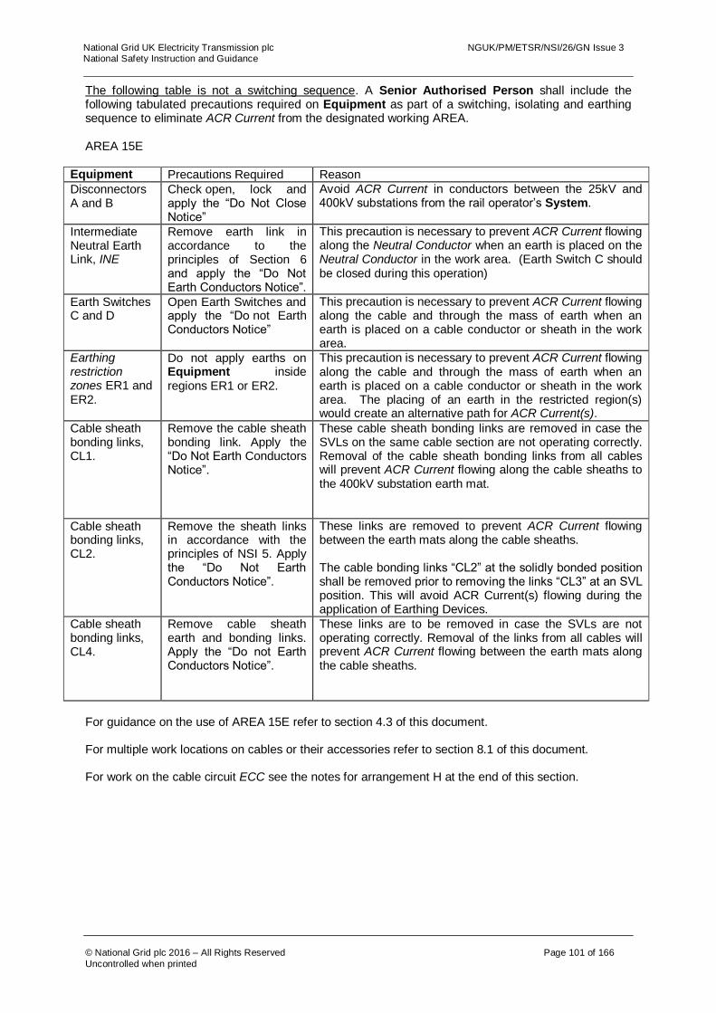
National Grid UK Electricity Transmission plc NGUK/PM/ETSR/NSI/26/GN Issue 3 National Safety Instruction and Guidance
© National Grid plc 2016 – All Rights Reserved Page 101 of 166
Uncontrolled when printed
The following table is not a switching sequence. A Senior Authorised Person shall include the following tabulated precautions required on Equipment as part of a switching, isolating and earthing sequence to eliminate ACR Current from the designated working AREA. AREA 15E
Equipment Precautions Required Reason
Disconnectors A and B
Check open, lock and apply the “Do Not Close Notice”
Avoid ACR Current in conductors between the 25kV and 400kV substations from the rail operator’s System.
Intermediate Neutral Earth Link, INE
Remove earth link in accordance to the principles of Section 6 and apply the “Do Not Earth Conductors Notice”.
This precaution is necessary to prevent ACR Current flowing along the Neutral Conductor when an earth is placed on the Neutral Conductor in the work area. (Earth Switch C should be closed during this operation)
Earth Switches C and D
Open Earth Switches and apply the “Do not Earth Conductors Notice”
This precaution is necessary to prevent ACR Current flowing along the cable and through the mass of earth when an earth is placed on a cable conductor or sheath in the work area.
Earthing restriction zones ER1 and ER2.
Do not apply earths on Equipment inside regions ER1 or ER2.
This precaution is necessary to prevent ACR Current flowing along the cable and through the mass of earth when an earth is placed on a cable conductor or sheath in the work area. The placing of an earth in the restricted region(s) would create an alternative path for ACR Current(s).
Cable sheath bonding links, CL1.
Remove the cable sheath bonding link. Apply the “Do Not Earth Conductors Notice”.
These cable sheath bonding links are removed in case the SVLs on the same cable section are not operating correctly. Removal of the cable sheath bonding links from all cables will prevent ACR Current flowing along the cable sheaths to the 400kV substation earth mat.
Cable sheath bonding links, CL2.
Remove the sheath links in accordance with the principles of NSI 5. Apply the “Do Not Earth Conductors Notice”.
These links are removed to prevent ACR Current flowing between the earth mats along the cable sheaths. The cable bonding links “CL2” at the solidly bonded position shall be removed prior to removing the links “CL3” at an SVL position. This will avoid ACR Current(s) flowing during the application of Earthing Devices.
Cable sheath bonding links, CL4.
Remove cable sheath earth and bonding links. Apply the “Do not Earth Conductors Notice”.
These links are to be removed in case the SVLs are not operating correctly. Removal of the links from all cables will prevent ACR Current flowing between the earth mats along the cable sheaths.
For guidance on the use of AREA 15E refer to section 4.3 of this document. For multiple work locations on cables or their accessories refer to section 8.1 of this document. For work on the cable circuit ECC see the notes for arrangement H at the end of this section.
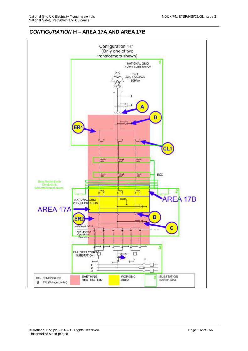
National Grid UK Electricity Transmission plc NGUK/PM/ETSR/NSI/26/GN Issue 3 National Safety Instruction and Guidance
© National Grid plc 2016 – All Rights Reserved Page 102 of 166
Uncontrolled when printed
CONFIGURATION H – AREA 17A AND AREA 17B
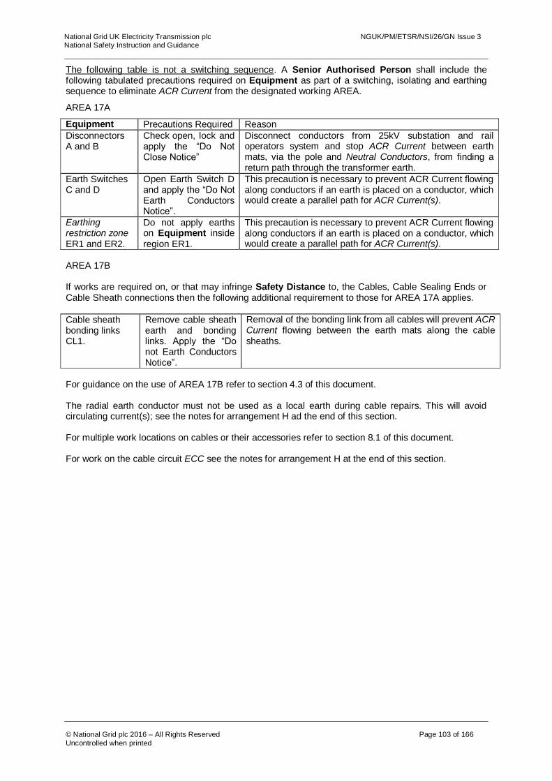
National Grid UK Electricity Transmission plc NGUK/PM/ETSR/NSI/26/GN Issue 3 National Safety Instruction and Guidance
© National Grid plc 2016 – All Rights Reserved Page 103 of 166
Uncontrolled when printed
The following table is not a switching sequence. A Senior Authorised Person shall include the following tabulated precautions required on Equipment as part of a switching, isolating and earthing sequence to eliminate ACR Current from the designated working AREA.
AREA 17A
Equipment Precautions Required Reason
Disconnectors A and B
Check open, lock and apply the “Do Not Close Notice”
Disconnect conductors from 25kV substation and rail operators system and stop ACR Current between earth mats, via the pole and Neutral Conductors, from finding a return path through the transformer earth.
Earth Switches C and D
Open Earth Switch D and apply the “Do Not Earth Conductors Notice”.
This precaution is necessary to prevent ACR Current flowing along conductors if an earth is placed on a conductor, which would create a parallel path for ACR Current(s).
Earthing restriction zone ER1 and ER2.
Do not apply earths on Equipment inside region ER1.
This precaution is necessary to prevent ACR Current flowing along conductors if an earth is placed on a conductor, which would create a parallel path for ACR Current(s).
AREA 17B If works are required on, or that may infringe Safety Distance to, the Cables, Cable Sealing Ends or Cable Sheath connections then the following additional requirement to those for AREA 17A applies.
Cable sheath bonding links CL1.
Remove cable sheath earth and bonding links. Apply the “Do not Earth Conductors Notice”.
Removal of the bonding link from all cables will prevent ACR Current flowing between the earth mats along the cable sheaths.
For guidance on the use of AREA 17B refer to section 4.3 of this document. The radial earth conductor must not be used as a local earth during cable repairs. This will avoid circulating current(s); see the notes for arrangement H ad the end of this section. For multiple work locations on cables or their accessories refer to section 8.1 of this document. For work on the cable circuit ECC see the notes for arrangement H at the end of this section.

National Grid UK Electricity Transmission plc NGUK/PM/ETSR/NSI/26/GN Issue 3 National Safety Instruction and Guidance
© National Grid plc 2016 – All Rights Reserved Page 104 of 166
Uncontrolled when printed
CONFIGURATION H – AREA 18

National Grid UK Electricity Transmission plc NGUK/PM/ETSR/NSI/26/GN Issue 3 National Safety Instruction and Guidance
© National Grid plc 2016 – All Rights Reserved Page 105 of 166
Uncontrolled when printed
The following table is not a switching sequence. A Senior Authorised Person shall include the following tabulated precautions required on Equipment as part of a switching, isolating and earthing sequence to eliminate ACR Current from the designated working AREA.
AREA 18
Equipment Precautions Required Reason
Disconnector A Check open, lock and apply the “Do Not Close Notice”
Disconnect conductors from 25kV substation and rail operators system and stop ACR Current between earth mats, via the pole and Neutral Conductors, from finding a return path through the transformer earth.
Earth Switch D Open Earth Switch D and apply the “Do Not Earth Conductors Notice”.
This precaution is necessary to prevent ACR Current flowing along conductors if an earth is placed on a conductor, which would create a parallel path for ACR Current(s).
Earthing restriction zone ER4 and ER5.
Do not apply earths on Equipment inside region ER1.
This precaution is necessary to prevent ACR Current flowing along conductors if an earth is placed on a conductor, which would create a parallel path for ACR Current(s).
Rail Operators Equipment Circuit Breaker F
Locked Open To stop any ACR current flow through the point of work and the C and A poles as a result of any earths being placed on the pole conductors in the rail operators system.
Rail Operators Equipment Links L1, L2 and Earth Position E1
Remove rail operator neutral links and ensure there is no earth applied to return conductor at position E1.
To stop any ACR current flow through the point of work and the Neutral Conductor as a result of earths on the rail operators system.
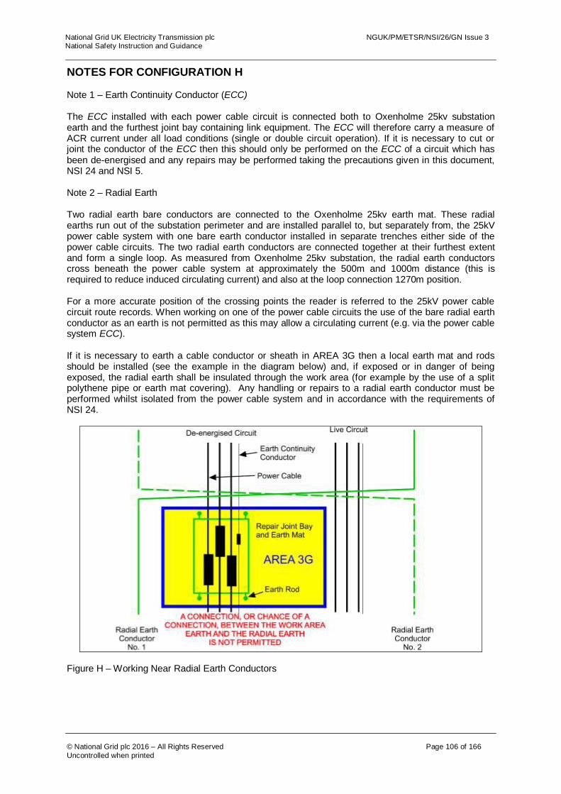
National Grid UK Electricity Transmission plc NGUK/PM/ETSR/NSI/26/GN Issue 3 National Safety Instruction and Guidance
© National Grid plc 2016 – All Rights Reserved Page 106 of 166
Uncontrolled when printed
NOTES FOR CONFIGURATION H Note 1 – Earth Continuity Conductor (ECC) The ECC installed with each power cable circuit is connected both to Oxenholme 25kv substation earth and the furthest joint bay containing link equipment. The ECC will therefore carry a measure of ACR current under all load conditions (single or double circuit operation). If it is necessary to cut or joint the conductor of the ECC then this should only be performed on the ECC of a circuit which has been de-energised and any repairs may be performed taking the precautions given in this document, NSI 24 and NSI 5. Note 2 – Radial Earth Two radial earth bare conductors are connected to the Oxenholme 25kv earth mat. These radial earths run out of the substation perimeter and are installed parallel to, but separately from, the 25kV power cable system with one bare earth conductor installed in separate trenches either side of the power cable circuits. The two radial earth conductors are connected together at their furthest extent and form a single loop. As measured from Oxenholme 25kv substation, the radial earth conductors cross beneath the power cable system at approximately the 500m and 1000m distance (this is required to reduce induced circulating current) and also at the loop connection 1270m position. For a more accurate position of the crossing points the reader is referred to the 25kV power cable circuit route records. When working on one of the power cable circuits the use of the bare radial earth conductor as an earth is not permitted as this may allow a circulating current (e.g. via the power cable system ECC). If it is necessary to earth a cable conductor or sheath in AREA 3G then a local earth mat and rods should be installed (see the example in the diagram below) and, if exposed or in danger of being exposed, the radial earth shall be insulated through the work area (for example by the use of a split polythene pipe or earth mat covering). Any handling or repairs to a radial earth conductor must be performed whilst isolated from the power cable system and in accordance with the requirements of NSI 24.
Figure H – Working Near Radial Earth Conductors

National Grid UK Electricity Transmission plc NGUK/PM/ETSR/NSI/26/GN Issue 3 National Safety Instruction and Guidance
© National Grid plc 2016 – All Rights Reserved Page 107 of 166
Uncontrolled when printed
This page has been left Blank

National Grid UK Electricity Transmission plc NGUK/PM/ETSR/NSI/26/GN Issue 3 National Safety Instruction and Guidance
© National Grid plc 2016 – All Rights Reserved Page 108 of 166
Uncontrolled when printed
CONFIGURATION I CONFIGURATION I – AREA 1

National Grid UK Electricity Transmission plc NGUK/PM/ETSR/NSI/26/GN Issue 3 National Safety Instruction and Guidance
© National Grid plc 2016 – All Rights Reserved Page 109 of 166
Uncontrolled when printed
The following table is not a switching sequence. A Senior Authorised Person shall include the following tabulated precautions required on Equipment as part of a switching, isolating and earthing sequence to eliminate ACR Current from the designated working AREA. AREA 1 Equipment Precautions Required Reason
Disconnector A Check open, lock and apply the “Do Not Close Notice”
To prevent any ACR Current from finding a return path through the work area.

National Grid UK Electricity Transmission plc NGUK/PM/ETSR/NSI/26/GN Issue 3 National Safety Instruction and Guidance
© National Grid plc 2016 – All Rights Reserved Page 110 of 166
Uncontrolled when printed
CONFIGURATION I – AREA 2
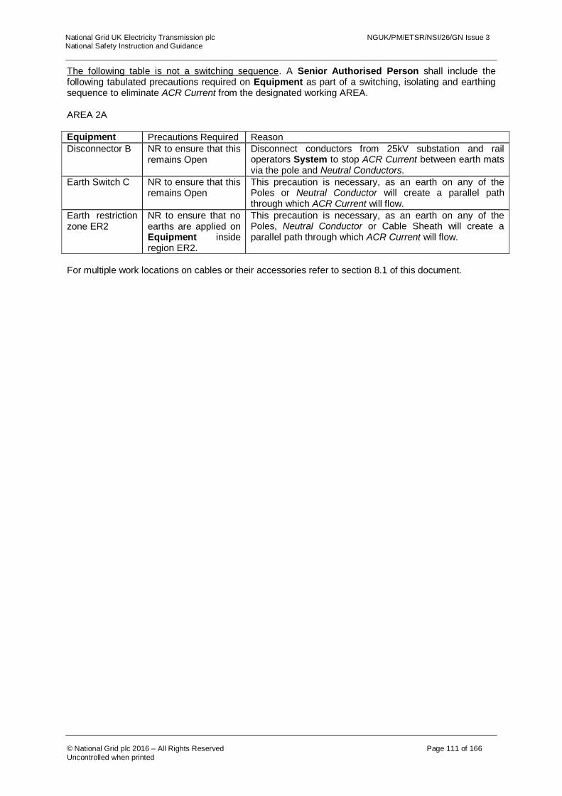
National Grid UK Electricity Transmission plc NGUK/PM/ETSR/NSI/26/GN Issue 3 National Safety Instruction and Guidance
© National Grid plc 2016 – All Rights Reserved Page 111 of 166
Uncontrolled when printed
The following table is not a switching sequence. A Senior Authorised Person shall include the following tabulated precautions required on Equipment as part of a switching, isolating and earthing sequence to eliminate ACR Current from the designated working AREA. AREA 2A Equipment Precautions Required Reason
Disconnector B NR to ensure that this remains Open
Disconnect conductors from 25kV substation and rail operators System to stop ACR Current between earth mats via the pole and Neutral Conductors.
Earth Switch C NR to ensure that this remains Open
This precaution is necessary, as an earth on any of the Poles or Neutral Conductor will create a parallel path through which ACR Current will flow.
Earth restriction zone ER2
NR to ensure that no earths are applied on Equipment inside region ER2.
This precaution is necessary, as an earth on any of the Poles, Neutral Conductor or Cable Sheath will create a parallel path through which ACR Current will flow.
For multiple work locations on cables or their accessories refer to section 8.1 of this document.

National Grid UK Electricity Transmission plc NGUK/PM/ETSR/NSI/26/GN Issue 3 National Safety Instruction and Guidance
© National Grid plc 2016 – All Rights Reserved Page 112 of 166
Uncontrolled when printed
CONFIGURATION J CONFIGURATION J – AREA 18

National Grid UK Electricity Transmission plc NGUK/PM/ETSR/NSI/26/GN Issue 3 National Safety Instruction and Guidance
© National Grid plc 2016 – All Rights Reserved Page 113 of 166
Uncontrolled when printed
The following table is not a switching sequence. A Senior Authorised Person shall include the following tabulated precautions on Equipment as part of a switching, isolating and earthing sequence to eliminate ACR Current from the designated working AREA. AREA 18
Equipment Precautions Required Reason
Disconnector A Check open, lock and apply the “Do Not Close Notice”
To prevent ACR Current from finding a return path through the work area.
Note: Both Pole and Neutral conductors are contained within a single oil filled cable. The cable includes a central 25kV Pole Conductor, concentric Neutral Conductor and a concentric outer metallic (lead) sheath. The lead sheath is solidly bonded to the substation earth mats at each end via a bolted connections (without cable sheath links) onto the substation earth mat. Note: Where conductors, metallic sheaths or armour wires of light current cables connect separate earth mats, then these connections shall only be broken or remade when all railway supply transformers on these earth mats are de-energised. This precaution is not required if it can be shown that there are no Dangers arising from the disconnection or reconnection of light current cabling earth mat interconnections.

National Grid UK Electricity Transmission plc NGUK/PM/ETSR/NSI/26/GN Issue 3 National Safety Instruction and Guidance
© National Grid plc 2016 – All Rights Reserved Page 114 of 166
Uncontrolled when printed
CONFIGURATION J – AREA 19 AND AREA 19B
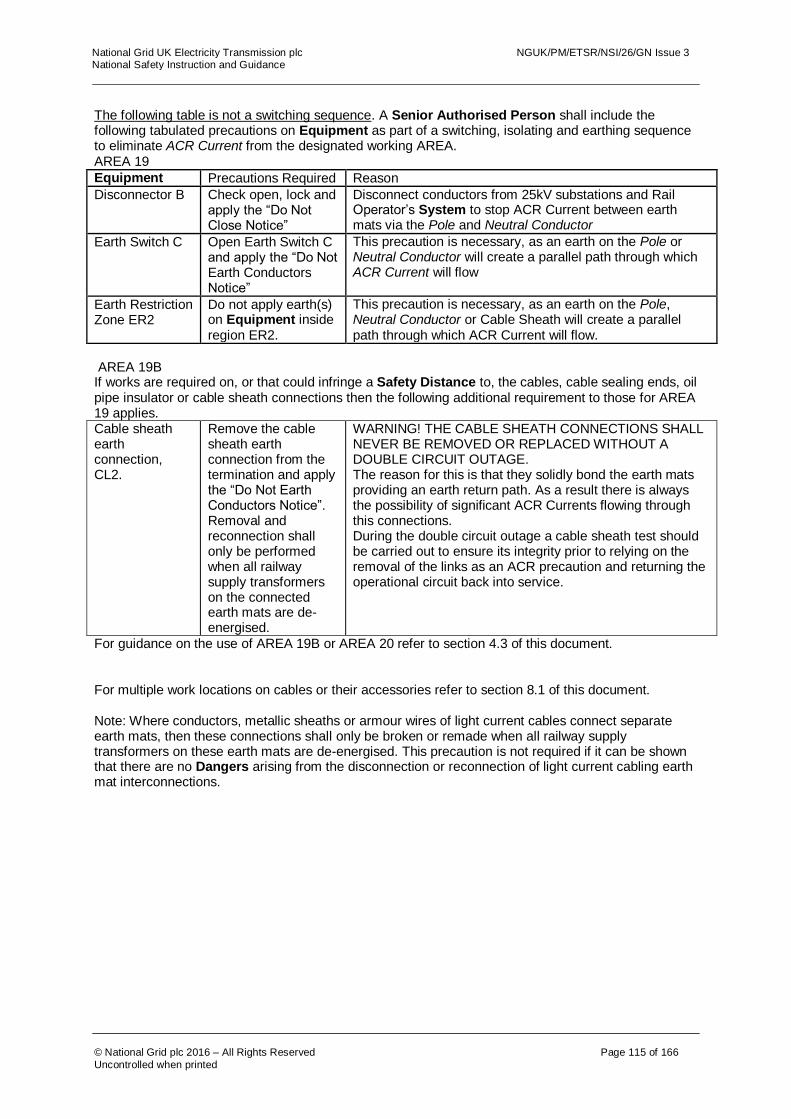
National Grid UK Electricity Transmission plc NGUK/PM/ETSR/NSI/26/GN Issue 3 National Safety Instruction and Guidance
© National Grid plc 2016 – All Rights Reserved Page 115 of 166
Uncontrolled when printed
The following table is not a switching sequence. A Senior Authorised Person shall include the following tabulated precautions on Equipment as part of a switching, isolating and earthing sequence to eliminate ACR Current from the designated working AREA. AREA 19
Equipment Precautions Required Reason
Disconnector B Check open, lock and apply the “Do Not Close Notice”
Disconnect conductors from 25kV substations and Rail Operator’s System to stop ACR Current between earth mats via the Pole and Neutral Conductor
Earth Switch C Open Earth Switch C and apply the “Do Not Earth Conductors Notice”
This precaution is necessary, as an earth on the Pole or Neutral Conductor will create a parallel path through which ACR Current will flow
Earth Restriction Zone ER2
Do not apply earth(s) on Equipment inside region ER2.
This precaution is necessary, as an earth on the Pole, Neutral Conductor or Cable Sheath will create a parallel path through which ACR Current will flow.
AREA 19B If works are required on, or that could infringe a Safety Distance to, the cables, cable sealing ends, oil pipe insulator or cable sheath connections then the following additional requirement to those for AREA 19 applies. Cable sheath earth connection, CL2.
Remove the cable sheath earth connection from the termination and apply the “Do Not Earth Conductors Notice”. Removal and reconnection shall only be performed when all railway supply transformers on the connected earth mats are de-energised.
WARNING! THE CABLE SHEATH CONNECTIONS SHALL NEVER BE REMOVED OR REPLACED WITHOUT A DOUBLE CIRCUIT OUTAGE. The reason for this is that they solidly bond the earth mats providing an earth return path. As a result there is always the possibility of significant ACR Currents flowing through this connections. During the double circuit outage a cable sheath test should be carried out to ensure its integrity prior to relying on the removal of the links as an ACR precaution and returning the operational circuit back into service.
For guidance on the use of AREA 19B or AREA 20 refer to section 4.3 of this document.
For multiple work locations on cables or their accessories refer to section 8.1 of this document.
Note: Where conductors, metallic sheaths or armour wires of light current cables connect separate earth mats, then these connections shall only be broken or remade when all railway supply transformers on these earth mats are de-energised. This precaution is not required if it can be shown that there are no Dangers arising from the disconnection or reconnection of light current cabling earth mat interconnections.
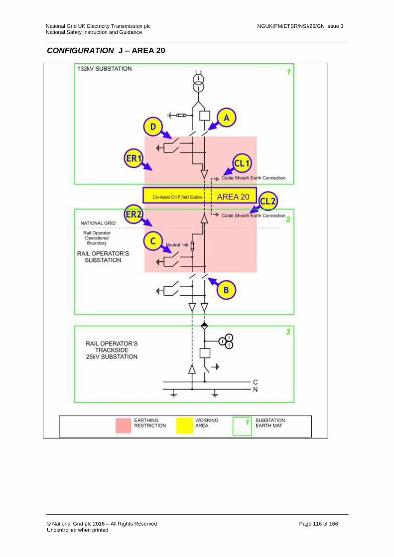
National Grid UK Electricity Transmission plc NGUK/PM/ETSR/NSI/26/GN Issue 3 National Safety Instruction and Guidance
© National Grid plc 2016 – All Rights Reserved Page 116 of 166
Uncontrolled when printed
CONFIGURATION J – AREA 20

National Grid UK Electricity Transmission plc NGUK/PM/ETSR/NSI/26/GN Issue 3 National Safety Instruction and Guidance
© National Grid plc 2016 – All Rights Reserved Page 117 of 166
Uncontrolled when printed
The following table is not a switching sequence. A Senior Authorised Person shall include the following tabulated precautions on Equipment as part of a switching, isolating and earthing sequence to eliminate ACR Current from the designated working AREA. AREA 20
Equipment Precautions Required Reason
Disconnectors A and B
Check open, lock and apply the “Do Not Earth Conductors Notice”
Avoid ACR Current in conductors between the 25kV and 132kV substations from the Rail Operators System.
Earth Switches C and D
Open Earth Switches and apply the “Do Not Earth Conductors Notice”.
This precaution is necessary to prevent ACR Current flowing along the cable and through the mass of earth when an earth is placed on a cable conductor or sheath in AREA 20
Earthing restriction zones ER1 and ER2.
Do not apply earths on Equipment inside regions ER1 or ER2.
This precaution is necessary to prevent ACR Current flowing along the cable and through the mass of earth when an earth is placed on a cable conductor or sheath in AREA 20. The placing of an earth in the restricted regions ER1 or ER2 would create an alternative path for ACR Current(s).
Cable sheath earth connections, CL1 and CL2.
Remove the cable sheath earth connections from the terminations and apply the “Do Not Earth Conductors Notice”. Removal and reconnections shall only be performed when all railway supply transformers on the connected earth mats are de-energised.
WARNING! THE CABLE SHEATH CONNECTIONS SHALL NEVER BE REMOVED OR REPLACED WITHOUT A DOUBLE CIRCUIT OUTAGE. The reason for this is that they solidly bond the earth mats providing an earth return path. As a result there is always the possibility of significant ACR Currents flowing through this connections. During the double circuit outage a cable sheath test should be carried out to ensure its integrity prior to relying on the removal of the links as an ACR precaution and returning the operational circuit back into service.
For guidance on the use of AREA 19B, AREA 21B or AREA 3 refer to Section 4.3 of this document. For multiple work locations on cables or their accessories refer to section 8.1 of this document.
Note: Where conductors, metallic sheaths or armour wires of light current cables connect separate earth mats, then these connections shall only be broken or remade when all railway supply transformers on these earth mats are de-energised. This precaution is not required if it can be shown that there are no Dangers arising from the disconnection or reconnection of light current cabling earth mat interconnections.
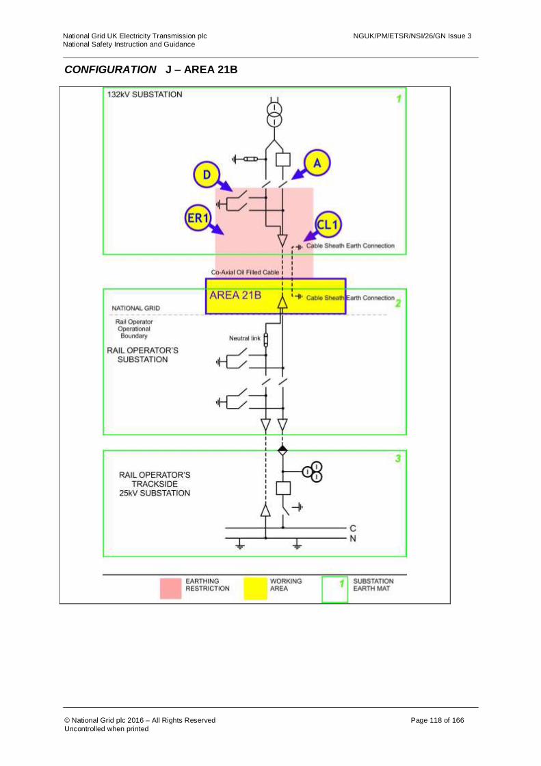
National Grid UK Electricity Transmission plc NGUK/PM/ETSR/NSI/26/GN Issue 3 National Safety Instruction and Guidance
© National Grid plc 2016 – All Rights Reserved Page 118 of 166
Uncontrolled when printed
CONFIGURATION J – AREA 21B

National Grid UK Electricity Transmission plc NGUK/PM/ETSR/NSI/26/GN Issue 3 National Safety Instruction and Guidance
© National Grid plc 2016 – All Rights Reserved Page 119 of 166
Uncontrolled when printed
The following table is not a switching sequence. A Senior Authorised Person shall include the following tabulated precautions on Equipment as part of a switching, isolating and earthing sequence to eliminate ACR Current from the designated working AREA. AREA 21B Equipment Precautions Required Reason
Disconnector A Check open, lock and apply and the “Do Not Close Notice”.
Disconnect conductors from 25kV substation and Rail Operators system and stop ACR Current between earth mats, via the pole and Neutral Conductors, find a return path through the transformer earth.
Earth Switch D Open Earth Switch D and apply the “Do Not Earth Conductors Notice”.
This precaution is necessary to prevent ACR Current flowing along conductors if an earth is placed on a conductor, which would create a parallel path for ACR Current(s).
Earthing Restriction Zone ER1
Do not apply earths on Equipment inside region ER1.
This precaution is necessary to prevent ACR Current flowing along conductors if an earth is placed on a conductor, which would create a parallel path for ACR Current(s).
Cable sheath earth connection, CL1.
Remove the cable sheath earth connection from the termination and apply the “Do Not Earth Conductors Notice”. Removal and reconnection shall only be performed when all railway supply transformers on the connected earth mats are de-energised.
The cable termination earth connection is to be removed as it is connected to the cable’s outer lead sheath and will carry ACR Current during the operation of any railway connection supply transformer. Additional precautions may be necessary to avoid the Dangers of impressed voltages (NSI 5). The links must be reinstalled before the circuit is energised.
For guidance on the use of AREA 21B or AREA 20 refer to section 4.3 of this document. For multiple work locations on cables or their accessories refer to section 8.1 of this document.
Note: Where conductors, metallic sheaths or armour wires of light current cables connect separate earth mats, then these connections shall only be broken or remade when all railway supply transformers on these earth mats are de-energised. This precaution is not required if it can be shown that there are no Dangers arising from the disconnection or reconnection of light current cabling earth mat interconnections.

National Grid UK Electricity Transmission plc NGUK/PM/ETSR/NSI/26/GN Issue 3 National Safety Instruction and Guidance
© National Grid plc 2016 – All Rights Reserved Page 120 of 166
Uncontrolled when printed
CONFIGURATION K CONFIGURATION K – AREA 1
Configuration K

National Grid UK Electricity Transmission plc NGUK/PM/ETSR/NSI/26/GN Issue 3 National Safety Instruction and Guidance
© National Grid plc 2016 – All Rights Reserved Page 121 of 166
Uncontrolled when printed
The following table is not a switching sequence. A Senior Authorised Person shall include the following tabulated precautions on Equipment as part of a switching, isolating and earthing sequence to eliminate ACR Current from the designated working AREA. AREA 1
Equipment Precautions Required Reason
Disconnector A Check open, lock and apply the “Do Not Close Notice”
Disconnect conductors connected to the Rail Operator’s System to stop ACR Current flowing through the point of work via the Pole and Neutral Conductors.
NOTE: The earth mat links connecting the National Grid’s earth mat to the Rail Operator’s earth mat must not be removed during the operation of any supplying transformer.
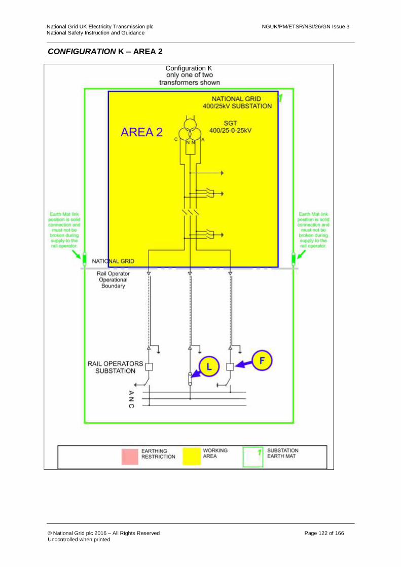
National Grid UK Electricity Transmission plc NGUK/PM/ETSR/NSI/26/GN Issue 3 National Safety Instruction and Guidance
© National Grid plc 2016 – All Rights Reserved Page 122 of 166
Uncontrolled when printed
CONFIGURATION K – AREA 2
Configuration K
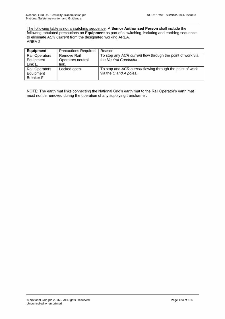
National Grid UK Electricity Transmission plc NGUK/PM/ETSR/NSI/26/GN Issue 3 National Safety Instruction and Guidance
© National Grid plc 2016 – All Rights Reserved Page 123 of 166
Uncontrolled when printed
The following table is not a switching sequence. A Senior Authorised Person shall include the following tabulated precautions on Equipment as part of a switching, isolating and earthing sequence to eliminate ACR Current from the designated working AREA. AREA 2
Equipment Precautions Required Reason
Rail Operators Equipment Link L.
Remove Rail Operators neutral link.
To stop any ACR current flow through the point of work via the Neutral Conductor.
Rail Operators Equipment Breaker F
Locked open To stop and ACR current flowing through the point of work via the C and A poles.
NOTE: The earth mat links connecting the National Grid’s earth mat to the Rail Operator’s earth mat must not be removed during the operation of any supplying transformer.

National Grid UK Electricity Transmission plc NGUK/PM/ETSR/NSI/26/GN Issue 3 National Safety Instruction and Guidance
© National Grid plc 2016 – All Rights Reserved Page 124 of 166
Uncontrolled when printed
CONFIGURATION L CONFIGURATION L – AREA 1
Configuration L

National Grid UK Electricity Transmission plc NGUK/PM/ETSR/NSI/26/GN Issue 3 National Safety Instruction and Guidance
© National Grid plc 2016 – All Rights Reserved Page 125 of 166
Uncontrolled when printed
The following table is not a switching sequence. A Senior Authorised Person shall include the following tabulated precautions on Equipment as part of a switching, isolating and earthing sequence to eliminate ACR Current from the designated working AREA. AREA 1
Equipment Precautions Required Reason
Disconnector A Check open, lock and apply the “Do Not Close Notice”
To prevent ACR Current from finding a return path through the work area.

National Grid UK Electricity Transmission plc NGUK/PM/ETSR/NSI/26/GN Issue 3 National Safety Instruction and Guidance
© National Grid plc 2016 – All Rights Reserved Page 126 of 166
Uncontrolled when printed
CONFIGURATION L – AREA 2A AND 2B
Configuration L
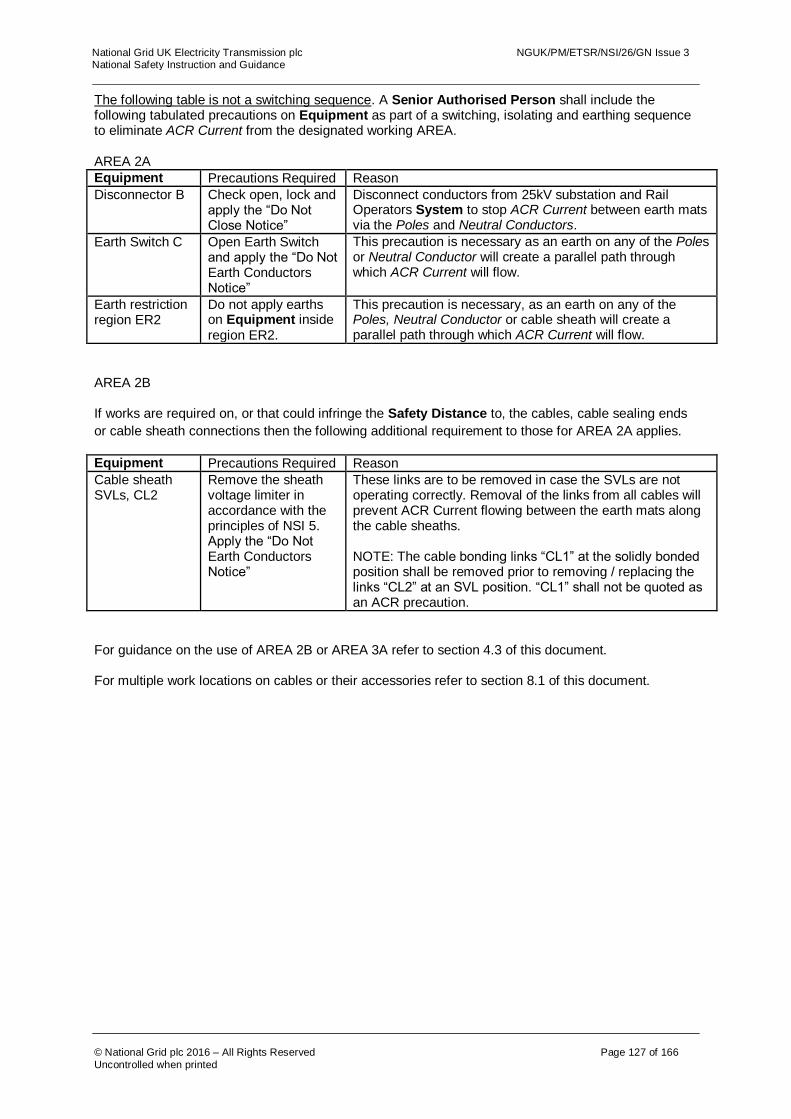
National Grid UK Electricity Transmission plc NGUK/PM/ETSR/NSI/26/GN Issue 3 National Safety Instruction and Guidance
© National Grid plc 2016 – All Rights Reserved Page 127 of 166
Uncontrolled when printed
The following table is not a switching sequence. A Senior Authorised Person shall include the following tabulated precautions on Equipment as part of a switching, isolating and earthing sequence to eliminate ACR Current from the designated working AREA. AREA 2A
Equipment Precautions Required Reason
Disconnector B Check open, lock and apply the “Do Not Close Notice”
Disconnect conductors from 25kV substation and Rail Operators System to stop ACR Current between earth mats via the Poles and Neutral Conductors.
Earth Switch C Open Earth Switch and apply the “Do Not Earth Conductors Notice”
This precaution is necessary as an earth on any of the Poles or Neutral Conductor will create a parallel path through which ACR Current will flow.
Earth restriction region ER2
Do not apply earths on Equipment inside region ER2.
This precaution is necessary, as an earth on any of the Poles, Neutral Conductor or cable sheath will create a parallel path through which ACR Current will flow.
AREA 2B
If works are required on, or that could infringe the Safety Distance to, the cables, cable sealing ends
or cable sheath connections then the following additional requirement to those for AREA 2A applies.
Equipment Precautions Required Reason
Cable sheath SVLs, CL2
Remove the sheath voltage limiter in accordance with the principles of NSI 5. Apply the “Do Not Earth Conductors Notice”
These links are to be removed in case the SVLs are not operating correctly. Removal of the links from all cables will prevent ACR Current flowing between the earth mats along the cable sheaths. NOTE: The cable bonding links “CL1” at the solidly bonded position shall be removed prior to removing / replacing the links “CL2” at an SVL position. “CL1” shall not be quoted as an ACR precaution.
For guidance on the use of AREA 2B or AREA 3A refer to section 4.3 of this document.
For multiple work locations on cables or their accessories refer to section 8.1 of this document.

National Grid UK Electricity Transmission plc NGUK/PM/ETSR/NSI/26/GN Issue 3 National Safety Instruction and Guidance
© National Grid plc 2016 – All Rights Reserved Page 128 of 166
Uncontrolled when printed
CONFIGURATION L– AREA 3A
Configuration L
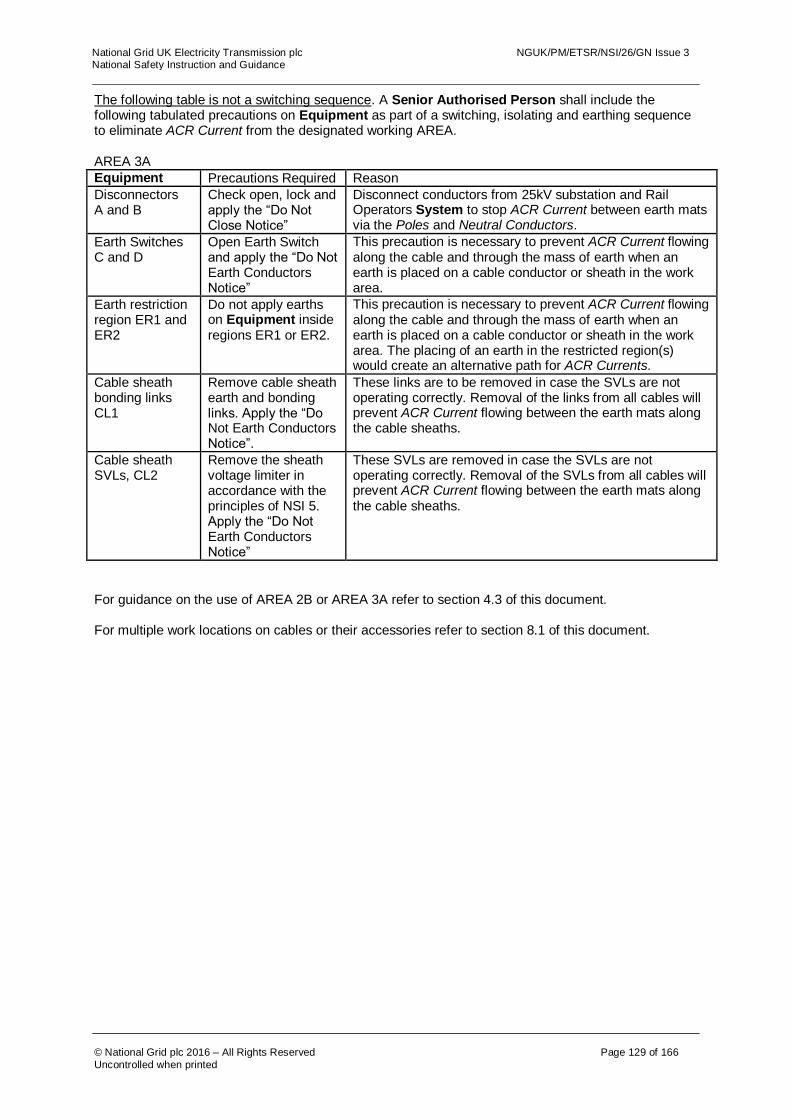
National Grid UK Electricity Transmission plc NGUK/PM/ETSR/NSI/26/GN Issue 3 National Safety Instruction and Guidance
© National Grid plc 2016 – All Rights Reserved Page 129 of 166
Uncontrolled when printed
The following table is not a switching sequence. A Senior Authorised Person shall include the following tabulated precautions on Equipment as part of a switching, isolating and earthing sequence to eliminate ACR Current from the designated working AREA. AREA 3A
Equipment Precautions Required Reason
Disconnectors A and B
Check open, lock and apply the “Do Not Close Notice”
Disconnect conductors from 25kV substation and Rail Operators System to stop ACR Current between earth mats via the Poles and Neutral Conductors.
Earth Switches C and D
Open Earth Switch and apply the “Do Not Earth Conductors Notice”
This precaution is necessary to prevent ACR Current flowing along the cable and through the mass of earth when an earth is placed on a cable conductor or sheath in the work area.
Earth restriction region ER1 and ER2
Do not apply earths on Equipment inside regions ER1 or ER2.
This precaution is necessary to prevent ACR Current flowing along the cable and through the mass of earth when an earth is placed on a cable conductor or sheath in the work area. The placing of an earth in the restricted region(s) would create an alternative path for ACR Currents.
Cable sheath bonding links CL1
Remove cable sheath earth and bonding links. Apply the “Do Not Earth Conductors Notice”.
These links are to be removed in case the SVLs are not operating correctly. Removal of the links from all cables will prevent ACR Current flowing between the earth mats along the cable sheaths.
Cable sheath SVLs, CL2
Remove the sheath voltage limiter in accordance with the principles of NSI 5. Apply the “Do Not Earth Conductors Notice”
These SVLs are removed in case the SVLs are not operating correctly. Removal of the SVLs from all cables will prevent ACR Current flowing between the earth mats along the cable sheaths.
For guidance on the use of AREA 2B or AREA 3A refer to section 4.3 of this document.
For multiple work locations on cables or their accessories refer to section 8.1 of this document.
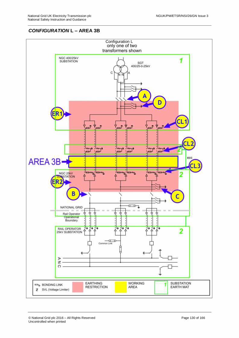
National Grid UK Electricity Transmission plc NGUK/PM/ETSR/NSI/26/GN Issue 3 National Safety Instruction and Guidance
© National Grid plc 2016 – All Rights Reserved Page 130 of 166
Uncontrolled when printed
CONFIGURATION L – AREA 3B
Configuration L
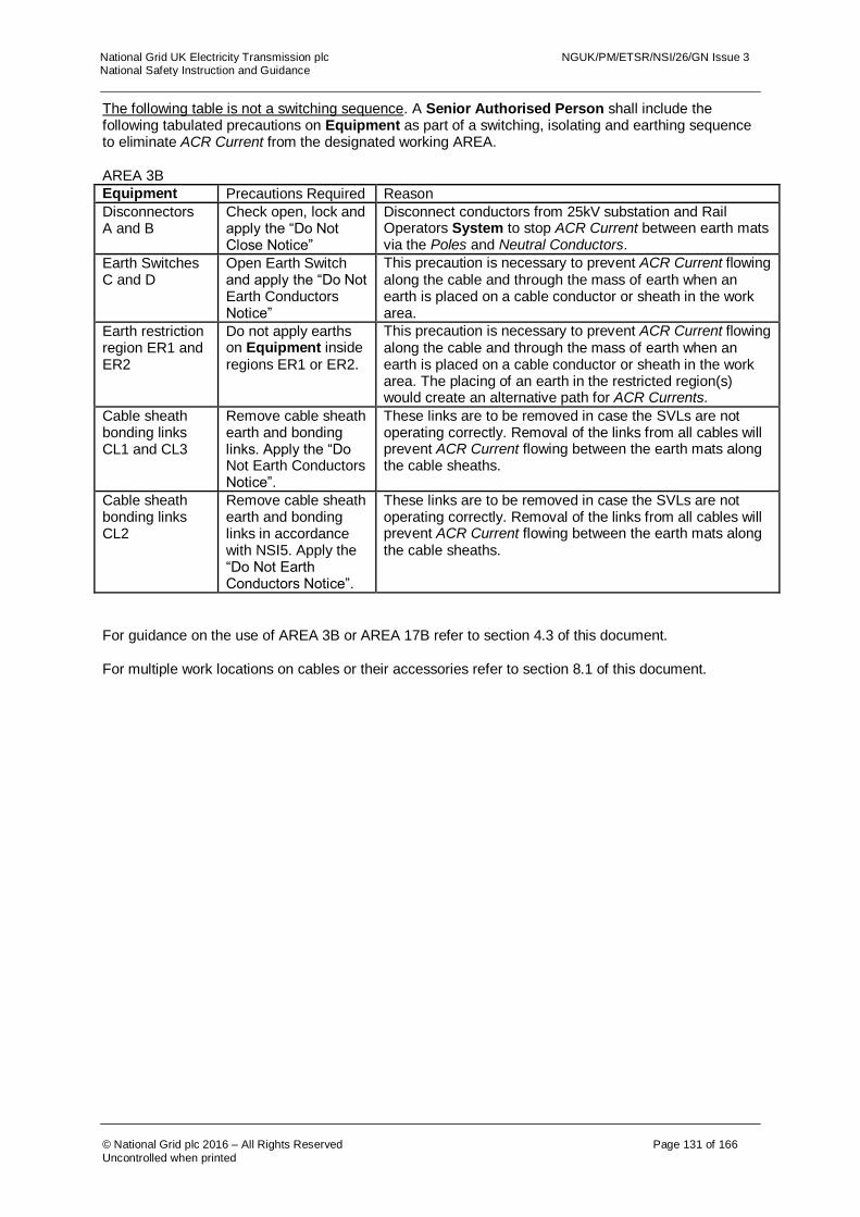
National Grid UK Electricity Transmission plc NGUK/PM/ETSR/NSI/26/GN Issue 3 National Safety Instruction and Guidance
© National Grid plc 2016 – All Rights Reserved Page 131 of 166
Uncontrolled when printed
The following table is not a switching sequence. A Senior Authorised Person shall include the following tabulated precautions on Equipment as part of a switching, isolating and earthing sequence to eliminate ACR Current from the designated working AREA. AREA 3B
Equipment Precautions Required Reason
Disconnectors A and B
Check open, lock and apply the “Do Not Close Notice”
Disconnect conductors from 25kV substation and Rail Operators System to stop ACR Current between earth mats via the Poles and Neutral Conductors.
Earth Switches C and D
Open Earth Switch and apply the “Do Not Earth Conductors Notice”
This precaution is necessary to prevent ACR Current flowing along the cable and through the mass of earth when an earth is placed on a cable conductor or sheath in the work area.
Earth restriction region ER1 and ER2
Do not apply earths on Equipment inside regions ER1 or ER2.
This precaution is necessary to prevent ACR Current flowing along the cable and through the mass of earth when an earth is placed on a cable conductor or sheath in the work area. The placing of an earth in the restricted region(s) would create an alternative path for ACR Currents.
Cable sheath bonding links CL1 and CL3
Remove cable sheath earth and bonding links. Apply the “Do Not Earth Conductors Notice”.
These links are to be removed in case the SVLs are not operating correctly. Removal of the links from all cables will prevent ACR Current flowing between the earth mats along the cable sheaths.
Cable sheath bonding links CL2
Remove cable sheath earth and bonding links in accordance with NSI5. Apply the “Do Not Earth Conductors Notice”.
These links are to be removed in case the SVLs are not operating correctly. Removal of the links from all cables will prevent ACR Current flowing between the earth mats along the cable sheaths.
For guidance on the use of AREA 3B or AREA 17B refer to section 4.3 of this document.
For multiple work locations on cables or their accessories refer to section 8.1 of this document.
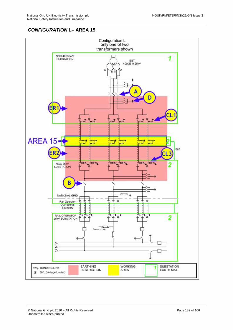
National Grid UK Electricity Transmission plc NGUK/PM/ETSR/NSI/26/GN Issue 3 National Safety Instruction and Guidance
© National Grid plc 2016 – All Rights Reserved Page 132 of 166
Uncontrolled when printed
CONFIGURATION L– AREA 15
Configuration L

National Grid UK Electricity Transmission plc NGUK/PM/ETSR/NSI/26/GN Issue 3 National Safety Instruction and Guidance
© National Grid plc 2016 – All Rights Reserved Page 133 of 166
Uncontrolled when printed
The following table is not a switching sequence. A Senior Authorised Person shall include the following tabulated precautions on Equipment as part of a switching, isolating and earthing sequence to eliminate ACR Current from the designated working AREA. AREA 15
Equipment Precautions Required Reason
Disconnectors A and B
Check open, lock and apply the “Do Not Close Notice”
Disconnect conductors from 25kV substation and Rail Operators System to stop ACR Current between earth mats via the Poles and Neutral Conductors.
Earth Switch D Open Earth Switch and apply the “Do Not Earth Conductors Notice”
This precaution is necessary to prevent ACR Current flowing along the cable and through the mass of earth when an earth is placed on a cable conductor or sheath in the work area..
Earth restriction region ER1 and ER2
Do not apply earths on Equipment inside regions ER1 or ER2.
This precaution is necessary to prevent ACR Current flowing along the cable and through the mass of earth when an earth is placed on a cable conductor or sheath in the work area. The placing of an earth in the restricted region(s) would create an alternative path for ACR Currents.
Cable sheath bonding links CL1 and CL3
Remove cable sheath earth and bonding links. Apply the “Do Not Earth Conductors Notice”.
These links are to be removed in case the SVLs are not operating correctly. Removal of the links from all cables will prevent ACR Current flowing between the earth mats along the cable sheaths.
For guidance on the use of AREA 15 refer to section 4.3 of this document.
For multiple work locations on cables or their accessories refer to section 8.1 of this document.

National Grid UK Electricity Transmission plc NGUK/PM/ETSR/NSI/26/GN Issue 3 National Safety Instruction and Guidance
© National Grid plc 2016 – All Rights Reserved Page 134 of 166
Uncontrolled when printed
CONFIGURATION L– AREA 17A AND 17B
Configuration L

National Grid UK Electricity Transmission plc NGUK/PM/ETSR/NSI/26/GN Issue 3 National Safety Instruction and Guidance
© National Grid plc 2016 – All Rights Reserved Page 135 of 166
Uncontrolled when printed
The following table is not a switching sequence. A Senior Authorised Person shall include the following tabulated precautions on Equipment as part of a switching, isolating and earthing sequence to eliminate ACR Current from the designated working AREA. AREA 17A
Equipment Precautions Required Reason
Disconnectors A and B
Check open, lock and apply the “Do Not Close Notice”
Disconnect conductors from 25kV substation and Rail Operators System to stop ACR Current between earth mats via the Poles and Neutral Conductors.
Earth Switch D Open Earth Switch and apply the “Do Not Earth Conductors Notice”
This precaution is necessary to prevent ACR Current flowing along the cable and through the mass of earth when an earth is placed on a cable conductor or sheath in the work area..
Earth restriction region ER1
Do not apply earths on Equipment inside regions ER1.
This precaution is necessary to prevent ACR Current flowing along the cable and through the mass of earth when an earth is placed on a cable conductor or sheath in the work area. The placing of an earth in the restricted region would create an alternative path for ACR Current(s).
AREA 17B
If works are required that may infringe Safety Distance to, the Cables, Cable sealing ends or Cable
Sheath connections then the following additional requirements to those for AREA 17A apply.
Equipment Precautions Required Reason
Cable sheath bonding links CL1
Remove cable sheath earth and bonding links. Apply the “Do Not Earth Conductors Notice”.
These links are to be removed in case the SVLs are not operating correctly. Removal of the links from all cables will prevent ACR Current flowing between the earth mats along the cable sheaths.
Cable sheath bonding links CL2
Remove cable sheath earth and bonding links in accordance with the requirements of NSI5. Apply the “Do Not Earth Conductors Notice”.
These links are to be removed in case the SVLs are not operating correctly. Removal of the links from all cables will prevent ACR Current flowing between the earth mats along the cable sheaths.
For guidance on the use of AREA 17B or AREA 3B refer to section 4.3 of this document.
For multiple work locations on cables or their accessories refer to section 8.1 of this document.

National Grid UK Electricity Transmission plc NGUK/PM/ETSR/NSI/26/GN Issue 3 National Safety Instruction and Guidance
© National Grid plc 2016 – All Rights Reserved Page 136 of 166
Uncontrolled when printed
CONFIGURATION L– AREA 18
Configuration L
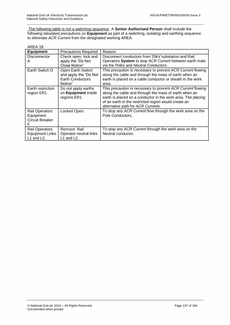
National Grid UK Electricity Transmission plc NGUK/PM/ETSR/NSI/26/GN Issue 3 National Safety Instruction and Guidance
© National Grid plc 2016 – All Rights Reserved Page 137 of 166
Uncontrolled when printed
The following table is not a switching sequence. A Senior Authorised Person shall include the following tabulated precautions on Equipment as part of a switching, isolating and earthing sequence to eliminate ACR Current from the designated working AREA. AREA 18
Equipment Precautions Required Reason
Disconnector A
Check open, lock and apply the “Do Not Close Notice”
Disconnect conductors from 25kV substation and Rail Operators System to stop ACR Current between earth mats via the Poles and Neutral Conductors.
Earth Switch D Open Earth Switch and apply the “Do Not Earth Conductors Notice”
This precaution is necessary to prevent ACR Current flowing along the cable and through the mass of earth when an earth is placed on a cable conductor or sheath in the work area.
Earth restriction region ER1
Do not apply earths on Equipment inside regions ER1
This precaution is necessary to prevent ACR Current flowing along the cable and through the mass of earth when an earth is placed on a conductor in the work area. The placing of an earth in the restricted region would create an alternative path for ACR Currents.
Rail Operators Equipment Circuit Breaker F
Locked Open. To stop any ACR Current flow through the work area on the Pole Conductors,
Rail Operators Equipment Links L1 and L2.
Remove Rail Operator neutral links L1 and L2.
To stop any ACR Current through the work area on the Neutral conductor.

National Grid UK Electricity Transmission plc NGUK/PM/ETSR/NSI/26/GN Issue 3 National Safety Instruction and Guidance
© National Grid plc 2016 – All Rights Reserved Page 138 of 166
Uncontrolled when printed
CONFIGURATION M CONFIGURATION M – AREA 1
Configuration M

National Grid UK Electricity Transmission plc NGUK/PM/ETSR/NSI/26/GN Issue 3 National Safety Instruction and Guidance
© National Grid plc 2016 – All Rights Reserved Page 139 of 166
Uncontrolled when printed
The following table is not a switching sequence. A Senior Authorised Person shall include the following tabulated precautions on Equipment as part of a switching, isolating and earthing sequence to eliminate ACR Current from the designated working AREA. AREA 1
Equipment Precautions Required Reason
Disconnector A Check open, lock and apply the “Do Not Close Notice”
To prevent ACR Current from finding a return path through the work area.

National Grid UK Electricity Transmission plc NGUK/PM/ETSR/NSI/26/GN Issue 3 National Safety Instruction and Guidance
© National Grid plc 2016 – All Rights Reserved Page 140 of 166
Uncontrolled when printed
CONFIGURATION M – AREA 2A AND 2B
Configuration M

National Grid UK Electricity Transmission plc NGUK/PM/ETSR/NSI/26/GN Issue 3 National Safety Instruction and Guidance
© National Grid plc 2016 – All Rights Reserved Page 141 of 166
Uncontrolled when printed
The following table is not a switching sequence. A Senior Authorised Person shall include the following tabulated precautions on Equipment as part of a switching, isolating and earthing sequence to eliminate ACR Current from the designated working AREA. AREA 2A
Equipment Precautions Required Reason
Disconnector B Check open, lock and apply the “Do Not Close Notice”
Disconnect conductors from 25kV substation and Rail Operators System to stop ACR Current between earth mats via the Poles and Neutral Conductors.
Earth Switch C Open Earth Switch c and apply the “Do Not Earth Conductors Notice”
This precaution is necessary as an earth on any of the Poles or Neutral Conductor will create a parallel path through which ACR Current will flow.
Earth restriction region ER2
Do not apply earths on Equipment inside region ER2.
This precaution is necessary, as an earth on any of the Poles, Neutral Conductor or cable sheath will create a parallel path through which ACR Current will flow.
AREA 2B
If works are required on, or that could infringe the Safety Distance to, the cables, cable sealing ends
or cable sheath connections then the following additional requirement to those for AREA 2A applies.
Equipment Precautions Required Reason
Cable sheath SVLs, CL2
Remove the sheath voltage limiter from the cable section passing into the work area in accordance with the principles of NSI 5. Apply the “Do Not Earth Conductors Notice”
These SVLs are removed in case the SVLs are not operating correctly. Removal of the SVLs from all cables will prevent ACR Current flowing between the earth mats along the cable sheaths. NOTE: The cable bonding links “CL1” at the solidly bonded position shall be removed prior to removing / replacing the SVL at “CL2” position. “CL1” shall not be quoted as an ACR precaution.
Cable sheath bonding links CL3
Remove cable sheath earth and bonding links. Apply the “Do Not Earth Conductors Notice”.
These links are to be removed in case the SVLs are not operating correctly. Removal of the links from all cables will prevent ACR Current flowing between the earth mats along the cable sheaths.
For guidance on the use of AREA 2B or AREA 3A refer to section 4.3 of this document.
For multiple work locations on cables or their accessories refer to section 8.1 of this document.
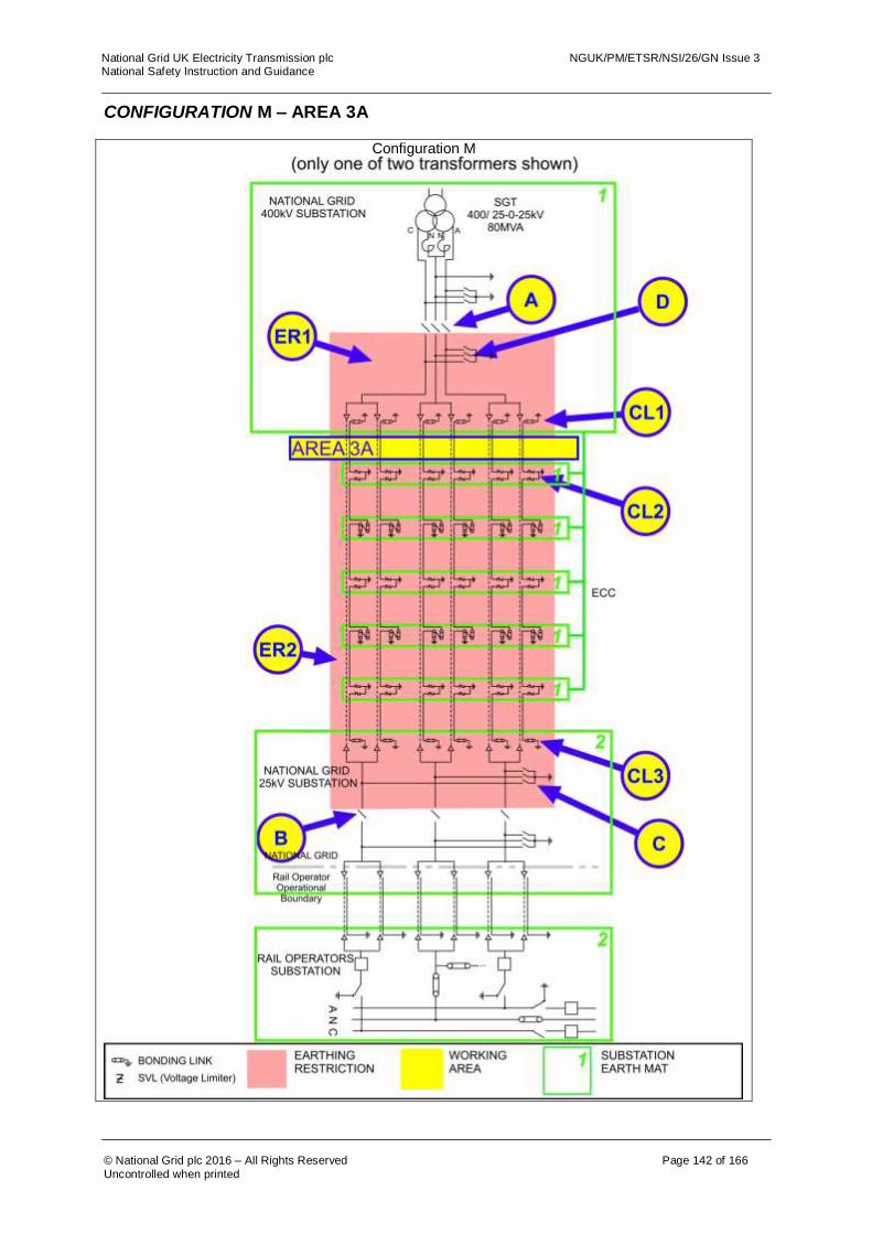
National Grid UK Electricity Transmission plc NGUK/PM/ETSR/NSI/26/GN Issue 3 National Safety Instruction and Guidance
© National Grid plc 2016 – All Rights Reserved Page 142 of 166
Uncontrolled when printed
CONFIGURATION M – AREA 3A
Configuration M

National Grid UK Electricity Transmission plc NGUK/PM/ETSR/NSI/26/GN Issue 3 National Safety Instruction and Guidance
© National Grid plc 2016 – All Rights Reserved Page 143 of 166
Uncontrolled when printed
The following table is not a switching sequence. A Senior Authorised Person shall include the following tabulated precautions on Equipment as part of a switching, isolating and earthing sequence to eliminate ACR Current from the designated working AREA. AREA 3A
Equipment Precautions Required Reason
Disconnectors A and B
Check open, lock and apply the “Do Not Close Notice”
Disconnect conductors from 25kV substation and Rail Operators System to stop ACR Current between earth mats via the Poles and Neutral Conductors.
Earth Switches C and D
Open Earth Switch and apply the “Do Not Earth Conductors Notice”
This precaution is necessary to prevent ACR Current flowing along the cable and through the mass of earth when an earth is placed on a cable conductor or sheath in the work area.
Earth restriction region ER1 and ER2
Do not apply earths on Equipment inside regions ER1 or ER2.
This precaution is necessary to prevent ACR Current flowing along the cable and through the mass of earth when an earth is placed on a cable conductor or sheath in the work area. The placing of an earth in the restricted region(s) would create an alternative path for ACR Currents.
Cable sheath bonding links CL1
Remove cable sheath earth and bonding links. Apply the “Do Not Earth Conductors Notice”.
These links are to be removed in case the SVLs are not operating correctly. Removal of the links from all cables will prevent ACR Current flowing between the earth mats along the cable sheaths.
Cable sheath SVLs, CL2
Remove the sheath voltage limiter from the cable section passing into the work area in accordance with the principles of NSI 5. Apply the “Do Not Earth Conductors Notice”
These SVLs are removed in case the SVLs are not operating correctly. Removal of the SVLs from all cables will prevent ACR Current flowing between the earth mats along the cable sheaths.
Cable sheath bonding links CL3
Remove cable sheath earth and bonding links. Apply the “Do Not Earth Conductors Notice”.
These links are to be removed in case the SVLs are not operating correctly. Removal of the links from all cables will prevent ACR Current flowing between the earth mats along the cable sheaths.
For guidance on the use of AREA 2B or AREA 3A refer to section 4.3 of this document.
For multiple work locations on cables or their accessories refer to section 8.1 of this document.

National Grid UK Electricity Transmission plc NGUK/PM/ETSR/NSI/26/GN Issue 3 National Safety Instruction and Guidance
© National Grid plc 2016 – All Rights Reserved Page 144 of 166
Uncontrolled when printed
CONFIGURATION M – AREA 3B
Configuration M
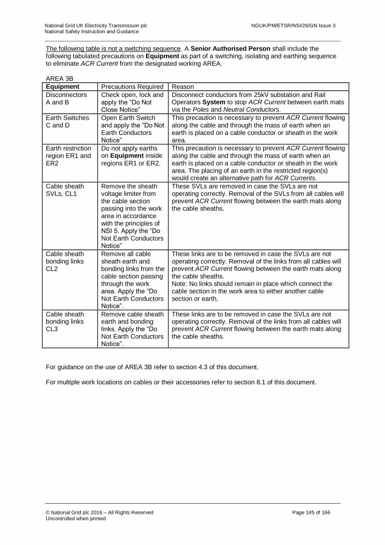
National Grid UK Electricity Transmission plc NGUK/PM/ETSR/NSI/26/GN Issue 3 National Safety Instruction and Guidance
© National Grid plc 2016 – All Rights Reserved Page 145 of 166
Uncontrolled when printed
The following table is not a switching sequence. A Senior Authorised Person shall include the following tabulated precautions on Equipment as part of a switching, isolating and earthing sequence to eliminate ACR Current from the designated working AREA. AREA 3B
Equipment Precautions Required Reason
Disconnectors A and B
Check open, lock and apply the “Do Not Close Notice”
Disconnect conductors from 25kV substation and Rail Operators System to stop ACR Current between earth mats via the Poles and Neutral Conductors.
Earth Switches C and D
Open Earth Switch and apply the “Do Not Earth Conductors Notice”
This precaution is necessary to prevent ACR Current flowing along the cable and through the mass of earth when an earth is placed on a cable conductor or sheath in the work area.
Earth restriction region ER1 and ER2
Do not apply earths on Equipment inside regions ER1 or ER2.
This precaution is necessary to prevent ACR Current flowing along the cable and through the mass of earth when an earth is placed on a cable conductor or sheath in the work area. The placing of an earth in the restricted region(s) would create an alternative path for ACR Currents.
Cable sheath SVLs, CL1
Remove the sheath voltage limiter from the cable section passing into the work area in accordance with the principles of NSI 5. Apply the “Do Not Earth Conductors Notice”
These SVLs are removed in case the SVLs are not operating correctly. Removal of the SVLs from all cables will prevent ACR Current flowing between the earth mats along the cable sheaths.
Cable sheath bonding links CL2
Remove all cable sheath earth and bonding links from the cable section passing through the work area. Apply the “Do Not Earth Conductors Notice”.
These links are to be removed in case the SVLs are not operating correctly. Removal of the links from all cables will prevent ACR Current flowing between the earth mats along the cable sheaths. Note: No links should remain in place which connect the cable section in the work area to either another cable section or earth,
Cable sheath bonding links CL3
Remove cable sheath earth and bonding links. Apply the “Do Not Earth Conductors Notice”.
These links are to be removed in case the SVLs are not operating correctly. Removal of the links from all cables will prevent ACR Current flowing between the earth mats along the cable sheaths.
For guidance on the use of AREA 3B refer to section 4.3 of this document.
For multiple work locations on cables or their accessories refer to section 8.1 of this document.

National Grid UK Electricity Transmission plc NGUK/PM/ETSR/NSI/26/GN Issue 3 National Safety Instruction and Guidance
© National Grid plc 2016 – All Rights Reserved Page 146 of 166
Uncontrolled when printed
CONFIGURATION M – AREA 3C Configuration M
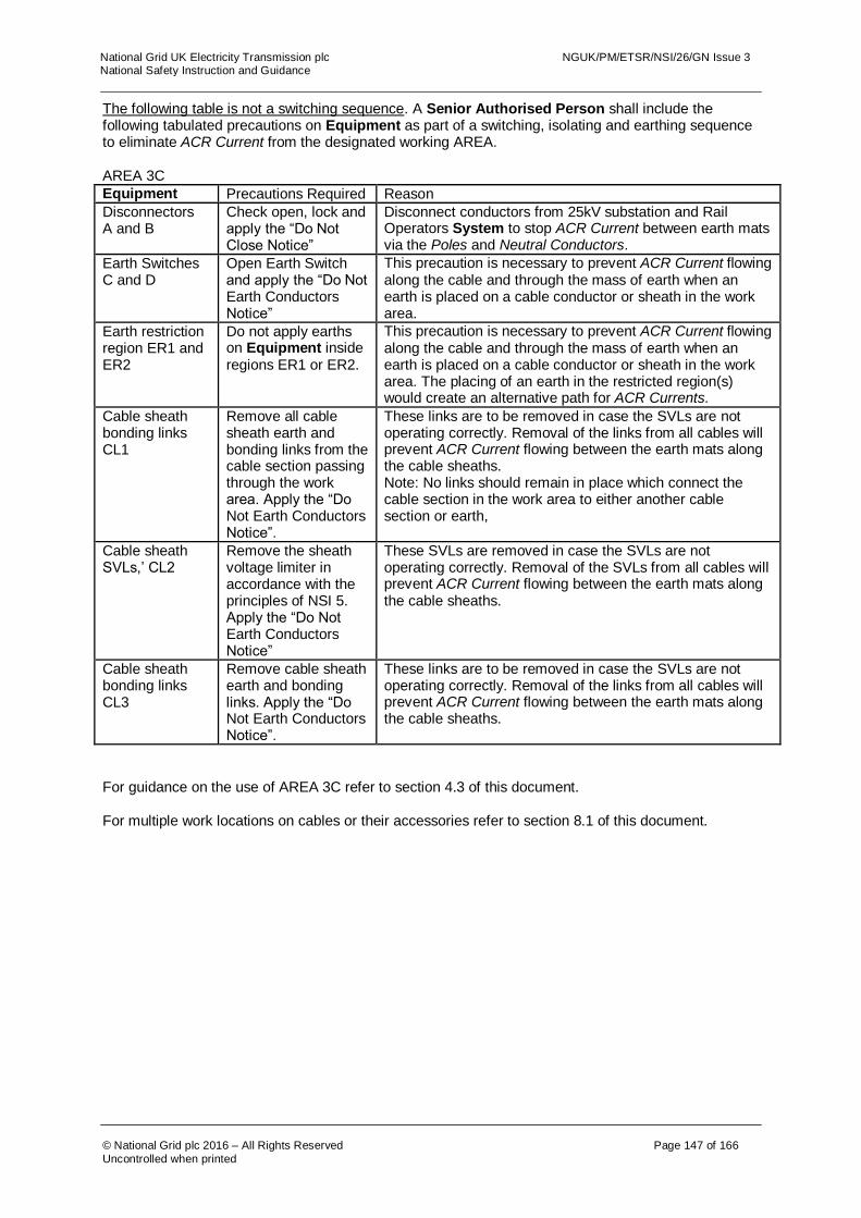
National Grid UK Electricity Transmission plc NGUK/PM/ETSR/NSI/26/GN Issue 3 National Safety Instruction and Guidance
© National Grid plc 2016 – All Rights Reserved Page 147 of 166
Uncontrolled when printed
The following table is not a switching sequence. A Senior Authorised Person shall include the following tabulated precautions on Equipment as part of a switching, isolating and earthing sequence to eliminate ACR Current from the designated working AREA. AREA 3C
Equipment Precautions Required Reason
Disconnectors A and B
Check open, lock and apply the “Do Not Close Notice”
Disconnect conductors from 25kV substation and Rail Operators System to stop ACR Current between earth mats via the Poles and Neutral Conductors.
Earth Switches C and D
Open Earth Switch and apply the “Do Not Earth Conductors Notice”
This precaution is necessary to prevent ACR Current flowing along the cable and through the mass of earth when an earth is placed on a cable conductor or sheath in the work area.
Earth restriction region ER1 and ER2
Do not apply earths on Equipment inside regions ER1 or ER2.
This precaution is necessary to prevent ACR Current flowing along the cable and through the mass of earth when an earth is placed on a cable conductor or sheath in the work area. The placing of an earth in the restricted region(s) would create an alternative path for ACR Currents.
Cable sheath bonding links CL1
Remove all cable sheath earth and bonding links from the cable section passing through the work area. Apply the “Do Not Earth Conductors Notice”.
These links are to be removed in case the SVLs are not operating correctly. Removal of the links from all cables will prevent ACR Current flowing between the earth mats along the cable sheaths. Note: No links should remain in place which connect the cable section in the work area to either another cable section or earth,
Cable sheath SVLs,’ CL2
Remove the sheath voltage limiter in accordance with the principles of NSI 5. Apply the “Do Not Earth Conductors Notice”
These SVLs are removed in case the SVLs are not operating correctly. Removal of the SVLs from all cables will prevent ACR Current flowing between the earth mats along the cable sheaths.
Cable sheath bonding links CL3
Remove cable sheath earth and bonding links. Apply the “Do Not Earth Conductors Notice”.
These links are to be removed in case the SVLs are not operating correctly. Removal of the links from all cables will prevent ACR Current flowing between the earth mats along the cable sheaths.
For guidance on the use of AREA 3C refer to section 4.3 of this document.
For multiple work locations on cables or their accessories refer to section 8.1 of this document.

National Grid UK Electricity Transmission plc NGUK/PM/ETSR/NSI/26/GN Issue 3 National Safety Instruction and Guidance
© National Grid plc 2016 – All Rights Reserved Page 148 of 166
Uncontrolled when printed
CONFIGURATION M – AREA 3D
Configuration M
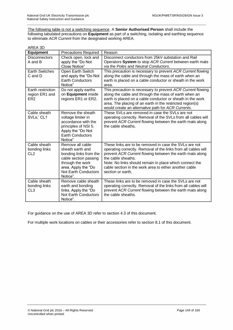
National Grid UK Electricity Transmission plc NGUK/PM/ETSR/NSI/26/GN Issue 3 National Safety Instruction and Guidance
© National Grid plc 2016 – All Rights Reserved Page 149 of 166
Uncontrolled when printed
The following table is not a switching sequence. A Senior Authorised Person shall include the following tabulated precautions on Equipment as part of a switching, isolating and earthing sequence to eliminate ACR Current from the designated working AREA. AREA 3D
Equipment Precautions Required Reason
Disconnectors A and B
Check open, lock and apply the “Do Not Close Notice”
Disconnect conductors from 25kV substation and Rail Operators System to stop ACR Current between earth mats via the Poles and Neutral Conductors.
Earth Switches C and D
Open Earth Switch and apply the “Do Not Earth Conductors Notice”
This precaution is necessary to prevent ACR Current flowing along the cable and through the mass of earth when an earth is placed on a cable conductor or sheath in the work area.
Earth restriction region ER1 and ER2
Do not apply earths on Equipment inside regions ER1 or ER2.
This precaution is necessary to prevent ACR Current flowing along the cable and through the mass of earth when an earth is placed on a cable conductor or sheath in the work area. The placing of an earth in the restricted region(s) would create an alternative path for ACR Currents.
Cable sheath SVLs,’ CL1
Remove the sheath voltage limiter in accordance with the principles of NSI 5. Apply the “Do Not Earth Conductors Notice”
These SVLs are removed in case the SVLs are not operating correctly. Removal of the SVLs from all cables will prevent ACR Current flowing between the earth mats along the cable sheaths.
Cable sheath bonding links CL2
Remove all cable sheath earth and bonding links from the cable section passing through the work area. Apply the “Do Not Earth Conductors Notice”.
These links are to be removed in case the SVLs are not operating correctly. Removal of the links from all cables will prevent ACR Current flowing between the earth mats along the cable sheaths. Note: No links should remain in place which connect the cable section in the work area to either another cable section or earth,
Cable sheath bonding links CL3
Remove cable sheath earth and bonding links. Apply the “Do Not Earth Conductors Notice”.
These links are to be removed in case the SVLs are not operating correctly. Removal of the links from all cables will prevent ACR Current flowing between the earth mats along the cable sheaths.
For guidance on the use of AREA 3D refer to section 4.3 of this document.
For multiple work locations on cables or their accessories refer to section 8.1 of this document.
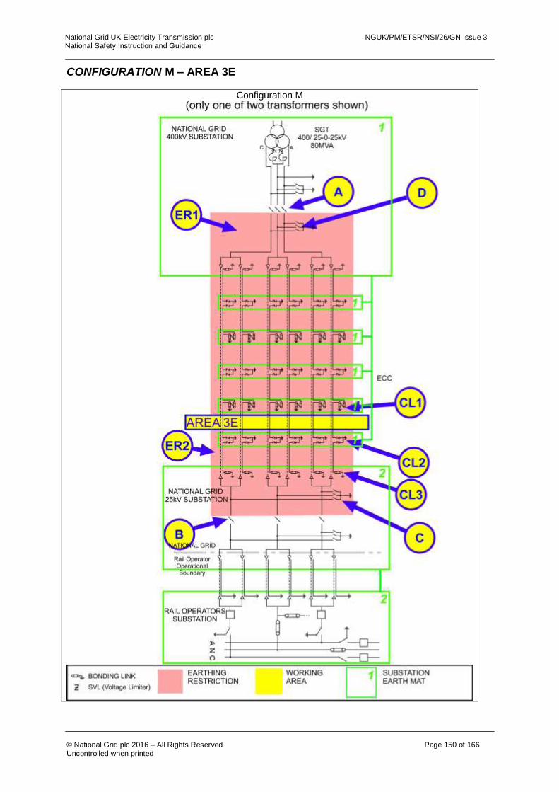
National Grid UK Electricity Transmission plc NGUK/PM/ETSR/NSI/26/GN Issue 3 National Safety Instruction and Guidance
© National Grid plc 2016 – All Rights Reserved Page 150 of 166
Uncontrolled when printed
CONFIGURATION M – AREA 3E
Configuration M

National Grid UK Electricity Transmission plc NGUK/PM/ETSR/NSI/26/GN Issue 3 National Safety Instruction and Guidance
© National Grid plc 2016 – All Rights Reserved Page 151 of 166
Uncontrolled when printed
The following table is not a switching sequence. A Senior Authorised Person shall include the following tabulated precautions on Equipment as part of a switching, isolating and earthing sequence to eliminate ACR Current from the designated working AREA. AREA 3E
Equipment Precautions Required Reason
Disconnectors A and B
Check open, lock and apply the “Do Not Close Notice”
Disconnect conductors from 25kV substation and Rail Operators System to stop ACR Current between earth mats via the Poles and Neutral Conductors.
Earth Switches C and D
Open Earth Switch and apply the “Do Not Earth Conductors Notice”
This precaution is necessary to prevent ACR Current flowing along the cable and through the mass of earth when an earth is placed on a cable conductor or sheath in the work area.
Earth restriction region ER1 and ER2
Do not apply earths on Equipment inside regions ER1 or ER2.
This precaution is necessary to prevent ACR Current flowing along the cable and through the mass of earth when an earth is placed on a cable conductor or sheath in the work area. The placing of an earth in the restricted region(s) would create an alternative path for ACR Currents.
Cable sheath bonding links CL1
Remove all cable sheath earth and bonding links from the cable section passing through the work area. Apply the “Do Not Earth Conductors Notice”.
These links are to be removed in case the SVLs are not operating correctly. Removal of the links from all cables will prevent ACR Current flowing between the earth mats along the cable sheaths. Note: No links should remain in place which connect the cable section in the work area to either another cable section or earth,
Cable sheath SVLs, CL2
Remove the sheath voltage limiter in accordance with the principles of NSI 5. Apply the “Do Not Earth Conductors Notice”
These SVLs are removed in case the SVLs are not operating correctly. Removal of the SVLs from all cables will prevent ACR Current flowing between the earth mats along the cable sheaths.
Cable sheath bonding links CL3
Remove cable sheath earth and bonding links. Apply the “Do Not Earth Conductors Notice”.
These links are to be removed in case the SVLs are not operating correctly. Removal of the links from all cables will prevent ACR Current flowing between the earth mats along the cable sheaths.
For guidance on the use of AREA 3E refer to section 4.3 of this document.
For multiple work locations on cables or their accessories refer to section 8.1 of this document.
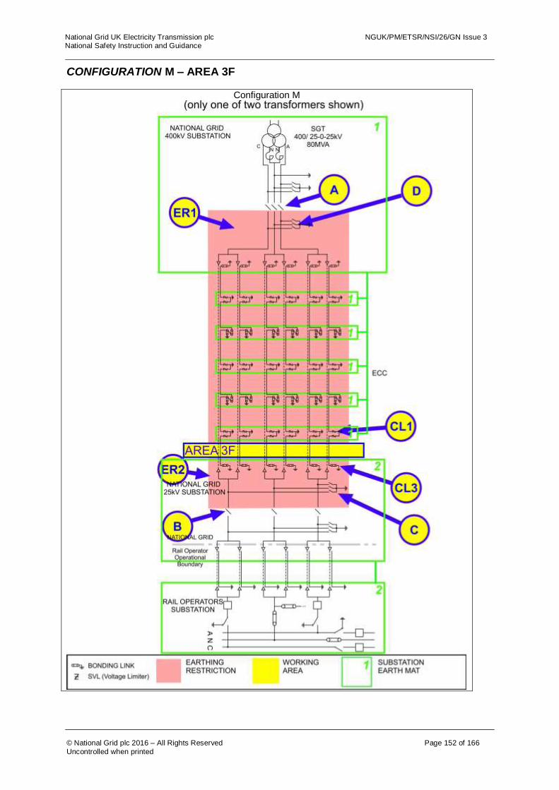
National Grid UK Electricity Transmission plc NGUK/PM/ETSR/NSI/26/GN Issue 3 National Safety Instruction and Guidance
© National Grid plc 2016 – All Rights Reserved Page 152 of 166
Uncontrolled when printed
CONFIGURATION M – AREA 3F
Configuration M

National Grid UK Electricity Transmission plc NGUK/PM/ETSR/NSI/26/GN Issue 3 National Safety Instruction and Guidance
© National Grid plc 2016 – All Rights Reserved Page 153 of 166
Uncontrolled when printed
The following table is not a switching sequence. A Senior Authorised Person shall include the following tabulated precautions on Equipment as part of a switching, isolating and earthing sequence to eliminate ACR Current from the designated working AREA. AREA 3F
Equipment Precautions Required Reason
Disconnectors A and B
Check open, lock and apply the “Do Not Close Notice”
Disconnect conductors from 25kV substation and Rail Operators System to stop ACR Current between earth mats via the Poles and Neutral Conductors.
Earth Switches C and D
Open Earth Switch and apply the “Do Not Earth Conductors Notice”
This precaution is necessary to prevent ACR Current flowing along the cable and through the mass of earth when an earth is placed on a cable conductor or sheath in the work area.
Earth restriction region ER1 and ER2
Do not apply earths on Equipment inside regions ER1 or ER2.
This precaution is necessary to prevent ACR Current flowing along the cable and through the mass of earth when an earth is placed on a cable conductor or sheath in the work area. The placing of an earth in the restricted region(s) would create an alternative path for ACR Currents.
Cable sheath SVLs, CL1
Remove the sheath voltage limiter in accordance with the principles of NSI 5. Apply the “Do Not Earth Conductors Notice”
These SVLs are removed in case the SVLs are not operating correctly. Removal of the SVLs from all cables will prevent ACR Current flowing between the earth mats along the cable sheaths.
Cable sheath bonding links CL3
Remove cable sheath earth and bonding links. Apply the “Do Not Earth Conductors Notice”.
These links are to be removed in case the SVLs are not operating correctly. Removal of the links from all cables will prevent ACR Current flowing between the earth mats along the cable sheaths.
For guidance on the use of AREA 3F or AREA 16B refer to section 4.3 of this document.
For multiple work locations on cables or their accessories refer to section 8.1 of this document.
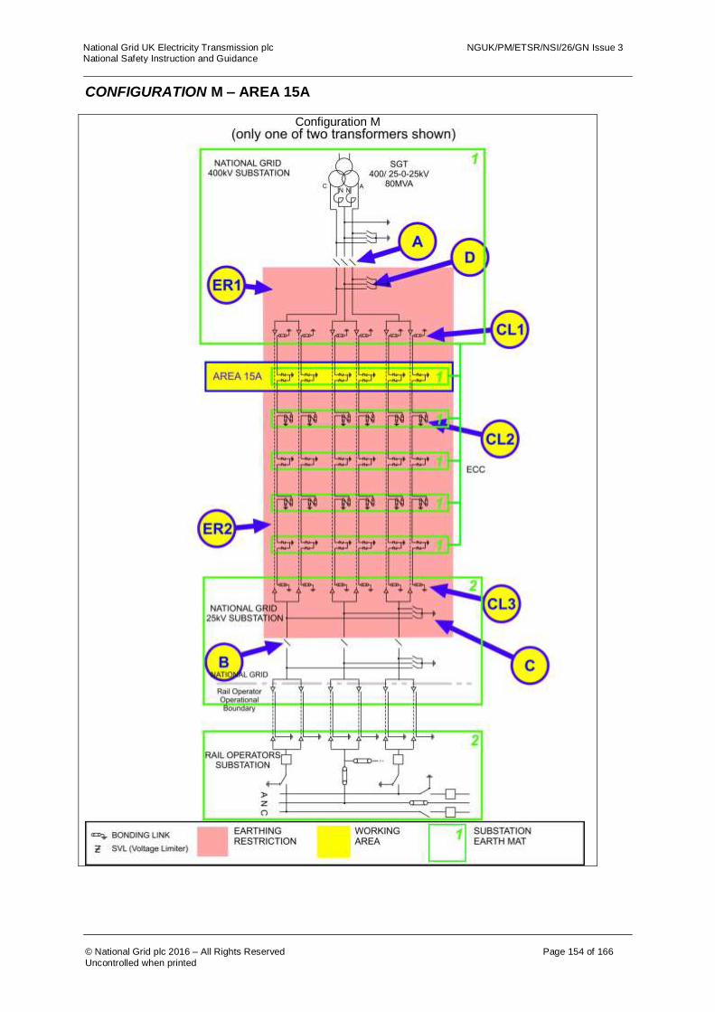
National Grid UK Electricity Transmission plc NGUK/PM/ETSR/NSI/26/GN Issue 3 National Safety Instruction and Guidance
© National Grid plc 2016 – All Rights Reserved Page 154 of 166
Uncontrolled when printed
CONFIGURATION M – AREA 15A
Configuration M

National Grid UK Electricity Transmission plc NGUK/PM/ETSR/NSI/26/GN Issue 3 National Safety Instruction and Guidance
© National Grid plc 2016 – All Rights Reserved Page 155 of 166
Uncontrolled when printed
The following table is not a switching sequence. A Senior Authorised Person shall include the following tabulated precautions on Equipment as part of a switching, isolating and earthing sequence to eliminate ACR Current from the designated working AREA. AREA 15A
Equipment Precautions Required Reason
Disconnectors A and B
Check open, lock and apply the “Do Not Close Notice”
Disconnect conductors from 25kV substation and Rail Operators System to stop ACR Current between earth mats via the Poles and Neutral Conductors.
Earth Switches C and D
Open Earth Switch and apply the “Do Not Earth Conductors Notice”
This precaution is necessary to prevent ACR Current flowing along the cable and through the mass of earth when an earth is placed on a cable conductor or sheath in the work area.
Earth restriction regionER1 and ER2
Do not apply earths on Equipment inside regions ER1 or ER2.
This precaution is necessary to prevent ACR Current flowing along the cable and through the mass of earth when an earth is placed on a cable conductor or sheath in the work area. The placing of an earth in the restricted region(s) would create an alternative path for ACR Currents.
Cable sheath bonding links CL1
Remove cable sheath earth and bonding links. Apply the “Do Not Earth Conductors Notice”.
These links are to be removed in case the SVLs are not operating correctly. Removal of the links from all cables will prevent ACR Current flowing between the earth mats along the cable sheaths.
Cable sheath bonding links CL2
Remove all cable sheath earth and bonding links from the cable section passing through the work area. Apply the “Do Not Earth Conductors Notice”.
These links are to be removed in case the SVLs are not operating correctly. Removal of the links from all cables will prevent ACR Current flowing between the earth mats along the cable sheaths. Note: No links should remain in place which connect the cable section in the work area to either another cable section or earth,
Cable sheath bonding links CL3
Remove cable sheath earth and bonding links. Apply the “Do Not Earth Conductors Notice”.
These links are to be removed in case the SVLs are not operating correctly. Removal of the links from all cables will prevent ACR Current flowing between the earth mats along the cable sheaths.
For guidance on the use of AREA 15A refer to section 4.3 of this document,
For multiple work locations on cables or their accessories refer to section 8.1 of this document.

National Grid UK Electricity Transmission plc NGUK/PM/ETSR/NSI/26/GN Issue 3 National Safety Instruction and Guidance
© National Grid plc 2016 – All Rights Reserved Page 156 of 166
Uncontrolled when printed
CONFIGURATION M – AREA 15B
Configuration M
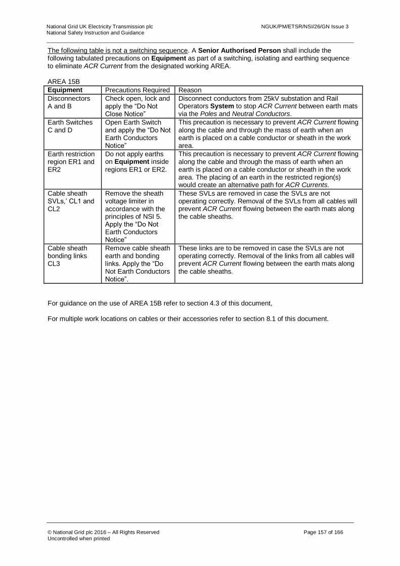
National Grid UK Electricity Transmission plc NGUK/PM/ETSR/NSI/26/GN Issue 3 National Safety Instruction and Guidance
© National Grid plc 2016 – All Rights Reserved Page 157 of 166
Uncontrolled when printed
The following table is not a switching sequence. A Senior Authorised Person shall include the following tabulated precautions on Equipment as part of a switching, isolating and earthing sequence to eliminate ACR Current from the designated working AREA. AREA 15B
Equipment Precautions Required Reason
Disconnectors A and B
Check open, lock and apply the “Do Not Close Notice”
Disconnect conductors from 25kV substation and Rail Operators System to stop ACR Current between earth mats via the Poles and Neutral Conductors.
Earth Switches C and D
Open Earth Switch and apply the “Do Not Earth Conductors Notice”
This precaution is necessary to prevent ACR Current flowing along the cable and through the mass of earth when an earth is placed on a cable conductor or sheath in the work area.
Earth restriction region ER1 and ER2
Do not apply earths on Equipment inside regions ER1 or ER2.
This precaution is necessary to prevent ACR Current flowing along the cable and through the mass of earth when an earth is placed on a cable conductor or sheath in the work area. The placing of an earth in the restricted region(s) would create an alternative path for ACR Currents.
Cable sheath SVLs,’ CL1 and CL2
Remove the sheath voltage limiter in accordance with the principles of NSI 5. Apply the “Do Not Earth Conductors Notice”
These SVLs are removed in case the SVLs are not operating correctly. Removal of the SVLs from all cables will prevent ACR Current flowing between the earth mats along the cable sheaths.
Cable sheath bonding links CL3
Remove cable sheath earth and bonding links. Apply the “Do Not Earth Conductors Notice”.
These links are to be removed in case the SVLs are not operating correctly. Removal of the links from all cables will prevent ACR Current flowing between the earth mats along the cable sheaths.
For guidance on the use of AREA 15B refer to section 4.3 of this document,
For multiple work locations on cables or their accessories refer to section 8.1 of this document.

National Grid UK Electricity Transmission plc NGUK/PM/ETSR/NSI/26/GN Issue 3 National Safety Instruction and Guidance
© National Grid plc 2016 – All Rights Reserved Page 158 of 166
Uncontrolled when printed
CONFIGURATION M – AREA 15C
Configuration M
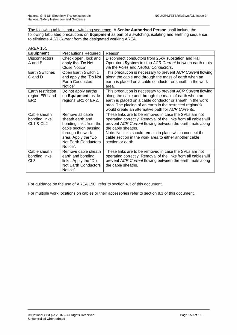
National Grid UK Electricity Transmission plc NGUK/PM/ETSR/NSI/26/GN Issue 3 National Safety Instruction and Guidance
© National Grid plc 2016 – All Rights Reserved Page 159 of 166
Uncontrolled when printed
The following table is not a switching sequence. A Senior Authorised Person shall include the following tabulated precautions on Equipment as part of a switching, isolating and earthing sequence to eliminate ACR Current from the designated working AREA. AREA 15C
Equipment Precautions Required Reason
Disconnectors A and B
Check open, lock and apply the “Do Not Close Notice”
Disconnect conductors from 25kV substation and Rail Operators System to stop ACR Current between earth mats via the Poles and Neutral Conductors.
Earth Switches C and D
Open Earth Switch c and apply the “Do Not Earth Conductors Notice”
This precaution is necessary to prevent ACR Current flowing along the cable and through the mass of earth when an earth is placed on a cable conductor or sheath in the work area.
Earth restriction region ER1 and ER2
Do not apply earths on Equipment inside regions ER1 or ER2.
This precaution is necessary to prevent ACR Current flowing along the cable and through the mass of earth when an earth is placed on a cable conductor or sheath in the work area. The placing of an earth in the restricted region(s) would create an alternative path for ACR Currents.
Cable sheath bonding links CL1 & CL2
Remove all cable sheath earth and bonding links from the cable section passing through the work area. Apply the “Do Not Earth Conductors Notice”.
These links are to be removed in case the SVLs are not operating correctly. Removal of the links from all cables will prevent ACR Current flowing between the earth mats along the cable sheaths. Note: No links should remain in place which connect the cable section in the work area to either another cable section or earth,
Cable sheath bonding links CL3
Remove cable sheath earth and bonding links. Apply the “Do Not Earth Conductors Notice”.
These links are to be removed in case the SVLs are not operating correctly. Removal of the links from all cables will prevent ACR Current flowing between the earth mats along the cable sheaths.
For guidance on the use of AREA 15C refer to section 4.3 of this document,
For multiple work locations on cables or their accessories refer to section 8.1 of this document.
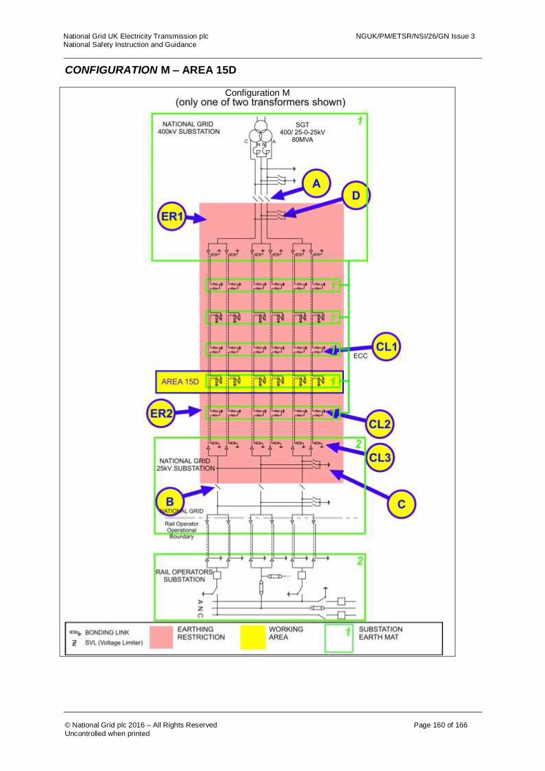
National Grid UK Electricity Transmission plc NGUK/PM/ETSR/NSI/26/GN Issue 3 National Safety Instruction and Guidance
© National Grid plc 2016 – All Rights Reserved Page 160 of 166
Uncontrolled when printed
CONFIGURATION M – AREA 15D
Configuration M

National Grid UK Electricity Transmission plc NGUK/PM/ETSR/NSI/26/GN Issue 3 National Safety Instruction and Guidance
© National Grid plc 2016 – All Rights Reserved Page 161 of 166
Uncontrolled when printed
The following table is not a switching sequence. A Senior Authorised Person shall include the following tabulated precautions on Equipment as part of a switching, isolating and earthing sequence to eliminate ACR Current from the designated working AREA. AREA 15D
Equipment Precautions Required Reason
Disconnectors A and B
Check open, lock and apply the “Do Not Close Notice”
Disconnect conductors from 25kV substation and Rail Operators System to stop ACR Current between earth mats via the Poles and Neutral Conductors.
Earth Switches C and D
Open Earth Switch and apply the “Do Not Earth Conductors Notice”
This precaution is necessary to prevent ACR Current flowing along the cable and through the mass of earth when an earth is placed on a cable conductor or sheath in the work area.
Earth restriction region ER1 and ER2
Do not apply earths on Equipment inside regions ER1 or ER2.
This precaution is necessary to prevent ACR Current flowing along the cable and through the mass of earth when an earth is placed on a cable conductor or sheath in the work area. The placing of an earth in the restricted region(s) would create an alternative path for ACR Currents.
Cable sheath SVLs, CL1 and CL2
Remove the sheath voltage limiter in accordance with the principles of NSI 5. Apply the “Do Not Earth Conductors Notice”
These SVLs are removed in case the SVLs are not operating correctly. Removal of the SVLs from all cables will prevent ACR Current flowing between the earth mats along the cable sheaths.
Cable sheath bonding links CL3
Remove cable sheath earth and bonding links. Apply the “Do Not Earth Conductors Notice”.
These links are to be removed in case the SVLs are not operating correctly. Removal of the links from all cables will prevent ACR Current flowing between the earth mats along the cable sheaths.
For guidance on the use of AREA 15D refer to section 4.3 of this document,
For multiple work locations on cables or their accessories refer to section 8.1 of this document.
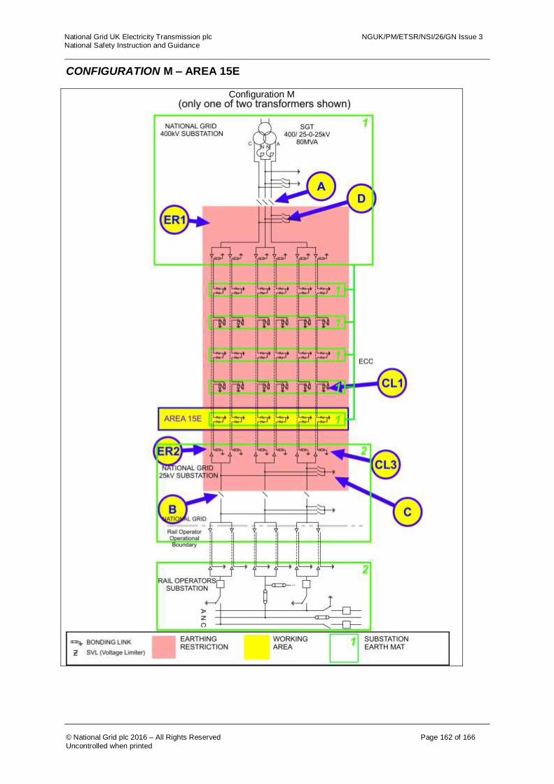
National Grid UK Electricity Transmission plc NGUK/PM/ETSR/NSI/26/GN Issue 3 National Safety Instruction and Guidance
© National Grid plc 2016 – All Rights Reserved Page 162 of 166
Uncontrolled when printed
CONFIGURATION M – AREA 15E
Configuration M

National Grid UK Electricity Transmission plc NGUK/PM/ETSR/NSI/26/GN Issue 3 National Safety Instruction and Guidance
© National Grid plc 2016 – All Rights Reserved Page 163 of 166
Uncontrolled when printed
The following table is not a switching sequence. A Senior Authorised Person shall include the following tabulated precautions on Equipment as part of a switching, isolating and earthing sequence to eliminate ACR Current from the designated working AREA. AREA 15E
Equipment Precautions Required Reason
Disconnectors A and B
Check open, lock and apply the “Do Not Close Notice”
Disconnect conductors from 25kV substation and Rail Operators System to stop ACR Current between earth mats via the Poles and Neutral Conductors.
Earth Switches C and D
Open Earth Switch and apply the “Do Not Earth Conductors Notice”
This precaution is necessary to prevent ACR Current flowing along the cable and through the mass of earth when an earth is placed on a cable conductor or sheath in the work area.
Earth restriction region ER1 and ER2
Do not apply earths on Equipment inside regions ER1 or ER2.
This precaution is necessary to prevent ACR Current flowing along the cable and through the mass of earth when an earth is placed on a cable conductor or sheath in the work area. The placing of an earth in the restricted region(s) would create an alternative path for ACR Currents.
Cable sheath bonding links CL1
Remove all cable sheath earth and bonding links from the cable section passing through the work area. Apply the “Do Not Earth Conductors Notice”.
These links are to be removed in case the SVLs are not operating correctly. Removal of the links from all cables will prevent ACR Current flowing between the earth mats along the cable sheaths. Note: No links should remain in place which connect the cable section in the work area to either another cable section or earth,
Cable sheath bonding links CL3
Remove cable sheath earth and bonding links. Apply the “Do Not Earth Conductors Notice”.
These links are to be removed in case the SVLs are not operating correctly. Removal of the links from all cables will prevent ACR Current flowing between the earth mats along the cable sheaths.
For guidance on the use of AREA 15E refer to section 4.3 of this document,
For multiple work locations on cables or their accessories refer to section 8.1 of this document.
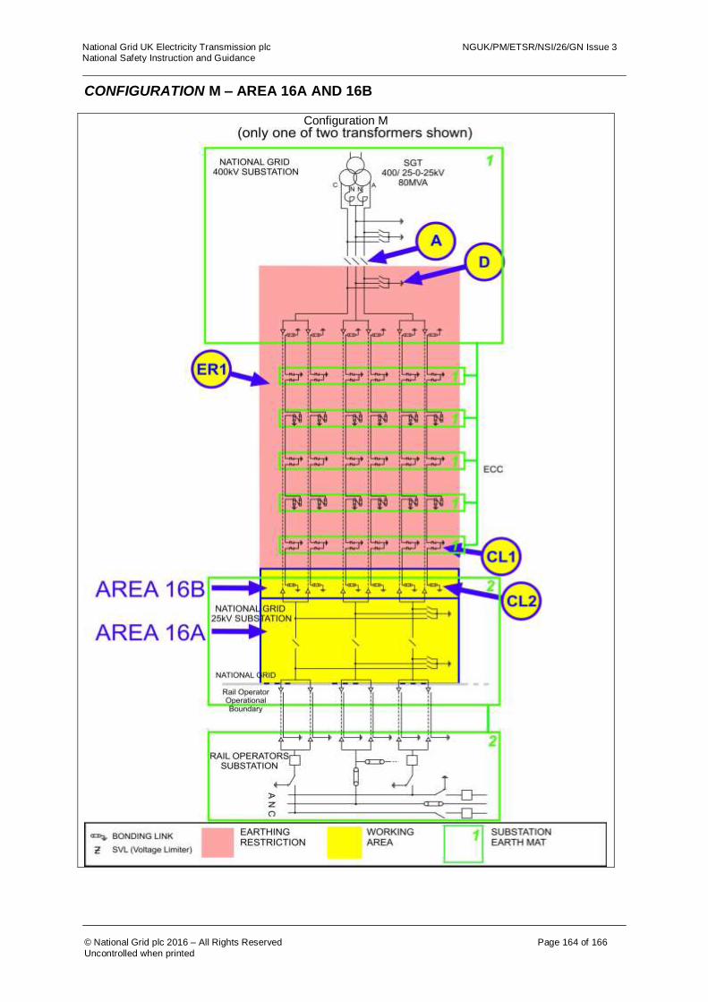
National Grid UK Electricity Transmission plc NGUK/PM/ETSR/NSI/26/GN Issue 3 National Safety Instruction and Guidance
© National Grid plc 2016 – All Rights Reserved Page 164 of 166
Uncontrolled when printed
CONFIGURATION M – AREA 16A AND 16B
Configuration M
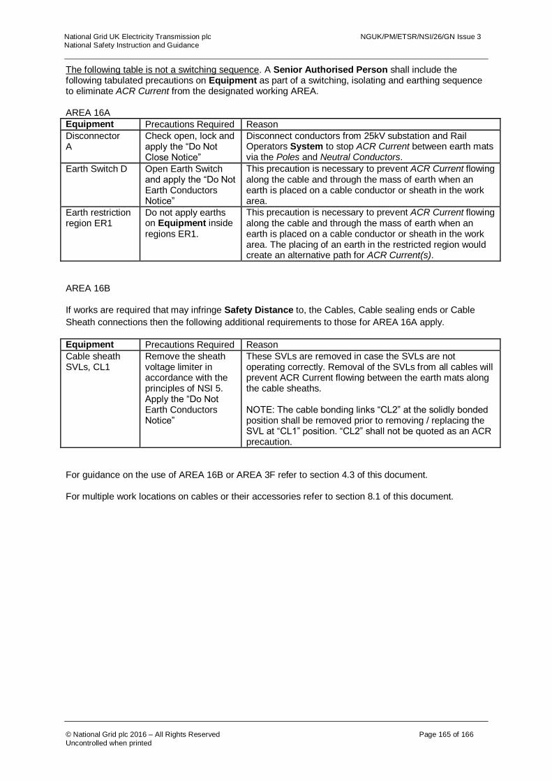
National Grid UK Electricity Transmission plc NGUK/PM/ETSR/NSI/26/GN Issue 3 National Safety Instruction and Guidance
© National Grid plc 2016 – All Rights Reserved Page 165 of 166
Uncontrolled when printed
The following table is not a switching sequence. A Senior Authorised Person shall include the following tabulated precautions on Equipment as part of a switching, isolating and earthing sequence to eliminate ACR Current from the designated working AREA. AREA 16A
Equipment Precautions Required Reason
Disconnector A
Check open, lock and apply the “Do Not Close Notice”
Disconnect conductors from 25kV substation and Rail Operators System to stop ACR Current between earth mats via the Poles and Neutral Conductors.
Earth Switch D Open Earth Switch and apply the “Do Not Earth Conductors Notice”
This precaution is necessary to prevent ACR Current flowing along the cable and through the mass of earth when an earth is placed on a cable conductor or sheath in the work area.
Earth restriction region ER1
Do not apply earths on Equipment inside regions ER1.
This precaution is necessary to prevent ACR Current flowing along the cable and through the mass of earth when an earth is placed on a cable conductor or sheath in the work area. The placing of an earth in the restricted region would create an alternative path for ACR Current(s).
AREA 16B
If works are required that may infringe Safety Distance to, the Cables, Cable sealing ends or Cable
Sheath connections then the following additional requirements to those for AREA 16A apply.
Equipment Precautions Required Reason
Cable sheath SVLs, CL1
Remove the sheath voltage limiter in accordance with the principles of NSI 5. Apply the “Do Not Earth Conductors Notice”
These SVLs are removed in case the SVLs are not operating correctly. Removal of the SVLs from all cables will prevent ACR Current flowing between the earth mats along the cable sheaths. NOTE: The cable bonding links “CL2” at the solidly bonded position shall be removed prior to removing / replacing the SVL at “CL1” position. “CL2” shall not be quoted as an ACR precaution.
For guidance on the use of AREA 16B or AREA 3F refer to section 4.3 of this document.
For multiple work locations on cables or their accessories refer to section 8.1 of this document.
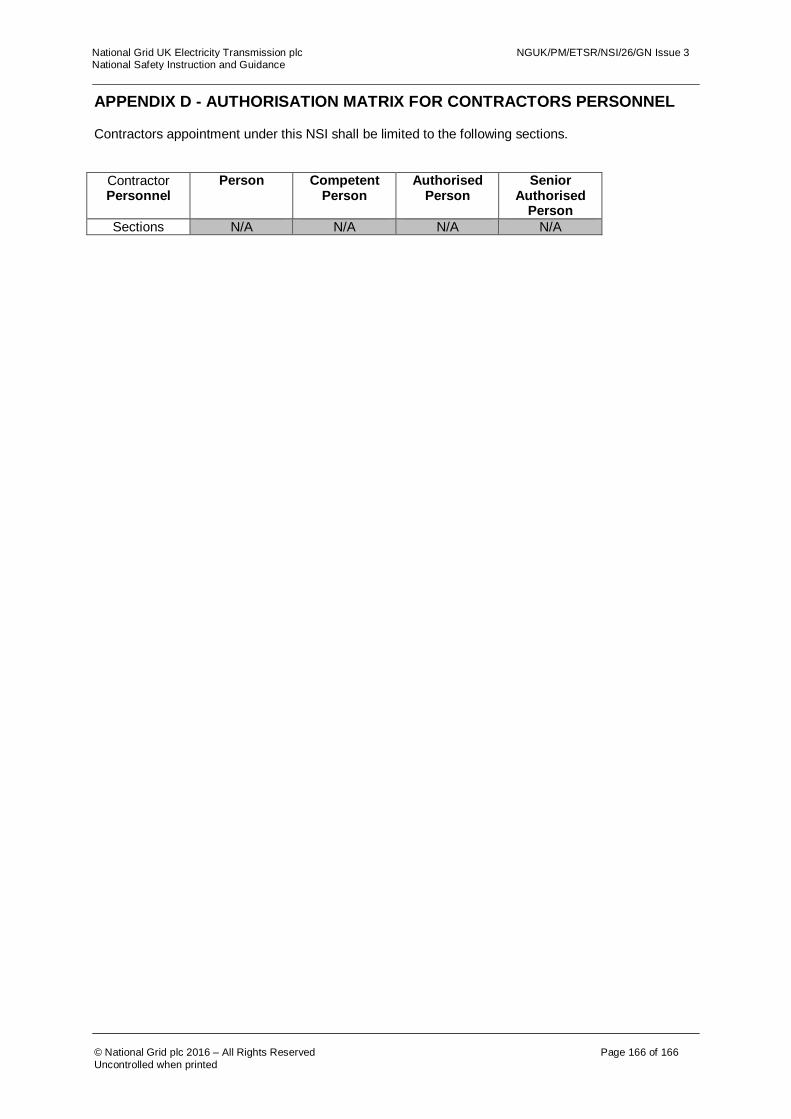
National Grid UK Electricity Transmission plc NGUK/PM/ETSR/NSI/26/GN Issue 3 National Safety Instruction and Guidance
© National Grid plc 2016 – All Rights Reserved Page 166 of 166
Uncontrolled when printed
APPENDIX D - AUTHORISATION MATRIX FOR CONTRACTORS PERSONNEL Contractors appointment under this NSI shall be limited to the following sections.
Contractor Personnel
Person Competent Person
Authorised Person
Senior Authorised
Person
Sections N/A N/A N/A N/A