NATIONAL GEODETIC SURVEY - Knowledge Base -...
41
NATIONAL GEODETIC SURVEY PROCESS ACTION TEAM 20 NATIONAL CONTINUOUSLY OPERATING REFERENCE STATION (NATIONAL CORS) SITE MONUMENTATION FINAL REPORT December 20, 2000 Team Members Roy Anderson Miranda Chin Michael Cline Dennis Hoar Orland Murray William Stone Facilitator Joyce Turpin ESC Liaison Dennis Milbert
Transcript of NATIONAL GEODETIC SURVEY - Knowledge Base -...
NATIONAL GEODETIC SURVEY
PROCESS ACTION TEAM 20
NATIONAL CONTINUOUSLY OPERATING REFERENCE STATION (NATIONAL CORS)
SITE MONUMENTATION
FINAL REPORT
December 20, 2000
Team Members
Roy AndersonMiranda ChinMichael ClineDennis Hoar
Orland MurrayWilliam Stone
Facilitator
Joyce Turpin
ESC Liaison
Dennis Milbert
-ii-
Table of Contents
Executive Summary . . . . . . . . . . . . . . . . . . . . . . . . . . . . . . . . . . . . . . . . . . . . . . . . . . . . . . . . . 1
Introduction . . . . . . . . . . . . . . . . . . . . . . . . . . . . . . . . . . . . . . . . . . . . . . . . . . . . . . . . . . . . . . . 2
Team's Purpose and Approach . . . . . . . . . . . . . . . . . . . . . . . . . . . . . . . . . . . . . . . . . . . . . . . . . 3
Existing Monumentation Designs . . . . . . . . . . . . . . . . . . . . . . . . . . . . . . . . . . . . . . . . . . . . . . 5Monument Structure . . . . . . . . . . . . . . . . . . . . . . . . . . . . . . . . . . . . . . . . . . . . . . . . . . 5
Pier . . . . . . . . . . . . . . . . . . . . . . . . . . . . . . . . . . . . . . . . . . . . . . . . . . . . . . . . . . 5Mast . . . . . . . . . . . . . . . . . . . . . . . . . . . . . . . . . . . . . . . . . . . . . . . . . . . . . . . . . 6Metal Rod/Pipe . . . . . . . . . . . . . . . . . . . . . . . . . . . . . . . . . . . . . . . . . . . . . . . . 7Building . . . . . . . . . . . . . . . . . . . . . . . . . . . . . . . . . . . . . . . . . . . . . . . . . . . . . . 7
Antenna Mount . . . . . . . . . . . . . . . . . . . . . . . . . . . . . . . . . . . . . . . . . . . . . . . . . . . . . . 8
Monumentation Design Issues . . . . . . . . . . . . . . . . . . . . . . . . . . . . . . . . . . . . . . . . . . . . . . . . 28GPS Signal Issues . . . . . . . . . . . . . . . . . . . . . . . . . . . . . . . . . . . . . . . . . . . . . . . . . . . 28Site Issues . . . . . . . . . . . . . . . . . . . . . . . . . . . . . . . . . . . . . . . . . . . . . . . . . . . . . . . . . . 29Construction Material Issues . . . . . . . . . . . . . . . . . . . . . . . . . . . . . . . . . . . . . . . . . . . 29Antenna Mounting Issues . . . . . . . . . . . . . . . . . . . . . . . . . . . . . . . . . . . . . . . . . . . . . . 30Miscellaneous Issues . . . . . . . . . . . . . . . . . . . . . . . . . . . . . . . . . . . . . . . . . . . . . . . . . 31
Recommendations . . . . . . . . . . . . . . . . . . . . . . . . . . . . . . . . . . . . . . . . . . . . . . . . . . . . . . . . . 32Monument Structure . . . . . . . . . . . . . . . . . . . . . . . . . . . . . . . . . . . . . . . . . . . . . . . . . 32Design Variations . . . . . . . . . . . . . . . . . . . . . . . . . . . . . . . . . . . . . . . . . . . . . . . . . . . . 34Antenna Mount . . . . . . . . . . . . . . . . . . . . . . . . . . . . . . . . . . . . . . . . . . . . . . . . . . . . . 34Reference Marks . . . . . . . . . . . . . . . . . . . . . . . . . . . . . . . . . . . . . . . . . . . . . . . . . . . . 35
Prototype Monument Installation . . . . . . . . . . . . . . . . . . . . . . . . . . . . . . . . . . . . . . . . . . . . . . 38
Conclusion . . . . . . . . . . . . . . . . . . . . . . . . . . . . . . . . . . . . . . . . . . . . . . . . . . . . . . . . . . . . . . . 39
Appendix A. Report on the Installation of the National CORS Prototype Monument
Appendix B. Guidelines for Setting a National CORS Monument
Book 1. Administrative Documents
Book 2. Reference Materials
-1-
Executive Summary
Process Action Team 20 (PAT 20) was established by the National Geodetic Survey (NGS)Executive Steering Committee (ESC) to develop design recommendations for a sitemonumentation system for future National Continuously Operating Reference Station(National CORS) operations. The Team's charter was issued on March 24, 1999 (with arevised charter issued on June 23, 1999). It defines PAT 20's ultimate goals as thedevelopment of recommendations for a monument design for future National CORSoperations and the deployment of a monument.
Modernization of the National Spatial Reference System (NSRS) is partially dependent onsuccessful implementation of (CORS) technology. CORS site monumentation is animportant aspect of the technology. A properly designed CORS monument provides a benignGPS signal environment and a high degree of positional stability.
The process of developing CORS monumentation design recommendations involved theinvestigation of various issues including: existing monumentation types, properties ofpotential monumentation materials, GPS signal reception factors, and CORS siteenvironment. PAT 20 examined a wide range of existing monumentation scenarios that arein use throughout the world.
PAT 20 recommends the following monument design for most future National CORSinstallations: a step-tiered cylindrical concrete pier that is a minimum depth of 10 ft. (3.0 m)by a minimum diameter of 1.5 ft. (0.46 m) below ground level, 5 ft. (1.5 m) tall by 1 ft. (0.3 m) diameter above ground, with an antenna mount consisting of a traditional tribrachadapter attached to a non-metallic base that is integrated into the concrete pier. The Teambelieves that this design is suitable for a wide range of site conditions and that it has anexcellent chance for long term endurance. This type of monument provides the high level ofhorizontal and vertical stability required for CORS applications. The monument's shape andmaterials have a negligible impact on the quality of the GPS signals. The materials are readilyavailable and affordable. The preparation of materials and the installation procedures arerelatively straightforward and require only a limited amount of specialized equipment andtechnique. The antenna can be locked in a true north orientation and will be force-centered toa repeatable position whenever it is removed and replaced.
On November 23-24, 1999, PAT 20 installed a prototype monument at the NGS facility inCorbin, Virginia. This prototype is based on the design recommendations developed by theTeam. The total cost for the services and materials involved in this installation was $688.30,excluding about 24 staff-hours of time from NGS employees.
PAT 20 was instructed also to address the issue of National CORS reference marks. Theteam recommends that NGS continue its current policy and procedures regarding NationalCORS reference marks.
-2-
Introduction
Continuously Operating Reference Stations (CORS) play a fundamental and essential role inthe establishment, definition, and utility of the National Spatial Reference System (NSRS). The future of the nation's positioning-related activities is dependent on properimplementation of CORS technology. The National Geodetic Survey (NGS) must thereforeperform the functions required to assure that the National CORS system is robust and viableand that it is capable of supporting the broad spectrum of the geospatial user community. Site monumentation is an extremely important aspect of CORS technology. CORSmonumentation must provide both a high degree of positional stability and an environmentthat has a minimal impact on the GPS signals. Implementation of the National CORSnetwork requires the involvement of many cooperating organizations. The monumentationmaterials, therefore, should be readily accessible, the installation procedure should bestraightforward, and the overall cost should be affordable.
Process Action Team 20 (PAT 20) was established to address the important issue of CORSsite monumentation. This report will discuss the process by which PAT 20 investigated thevarious technical issues pertaining to CORS monumentation. It will present a summary ofsome representative existing monumentation systems that were researched. This will befollowed by a discussion of the pertinent issues and constraints that impact the specificationof a design. Finally, a set of CORS site monumentation design recommendations, as well asinformation about the resultant prototype monument installation, will be presented. A varietyof related background and research materials pertaining to the Team's efforts is included withthis report (Book 2).
-3-
Team's Purpose and Approach
The NGS Executive Steering Committee (ESC) established PAT 20 by issuing the Team'scharter on March 24, 1999. Partway into its process, the Team requested clarification ofsome elements of the charter. In response, the ESC issued a revised charter on June 23, 1999. As outlined in the charter, PAT 20's ultimate goals were to recommend a site monumentationsystem for future National CORS operations and to deploy such a system. The charterdefines the term "site monumentation" as referring to "mounting a GPS antenna, establishingnearby ground markers, and determining relative position between the antenna referencepoint and those nearby ground markers." The Team was instructed to make the appropriatecontacts necessary to gather information on existing CORS-like monumentationconfigurations and to evaluate these options with a consideration of stability, permanence,and cost. Evaluation criteria were to include thermal expansion and multipath effects, otherelectrical characteristics, and any other issues deemed appropriate by the Team. The Teamwould then develop monumentation design recommendations and use these as the blueprintfor a prototype deployment. This report provides the pertinent information for thepublication of a NGS Technical Memorandum.
The first Team meeting was held on May 5, 1999. Meetings thereafter were held weekly,with only a few hiatuses caused by Team members' conflicting commitments. The Teamheld a total of 44 meetings. The Team’s final meeting was held on April 06, 2000. The NGSindividuals that comprised PAT 20 are listed on the cover of this report. All meetings wereheld in the Silver Spring Metro Center - Building 3. Three PAT 20 members attended themeetings by way of telephone conference call due to their remote duty stations. Dennis Hoarwas elected Team Leader and Roy Anderson was elected Alternate Team Leader. SidSafford helped facilitate the first meeting. Joyce Turpin then took over the role of Facilitator.Dennis Milbert attended the first meeting to provide an ESC perspective to the Team. EarlyTeam activities included the establishment of Team operating procedures and rules ofconduct. Team members took turns serving as note-taker and recorder. The Team Charter,Operating Procedures, Rules of Conduct, and Minutes from all Team meetings are in Book 1.
The Team's approach included the compilation and discussion of information about existingCORS monumentation. Team members made personal contact with many individualsoutside of NGS to gather pertinent information. The Team asked three NGS employees tospeak about various aspects of CORS technology. Neil Weston shared his knowledge ofsome of the monumentation configurations that comprise the current National CORSnetwork. He focused his discussion on monumentation stability issues, using positional time-series plots from three National CORS sites (Columbia, Lake Houston, and New Jersey IT) asillustration. David Crump discussed several specific National CORS monument designs,with an emphasis on details about their construction procedures. He also brought a sampleUniversity NAVSTAR Consortium (UNAVCO) antenna leveling mount for Team membersto assess. Gerald Mader presented his recommendations about monumentation design. Heemphasized signal-environment issues including multipath, signal resonance, and radiometricproblems caused by the presence of metal. The Team's discussions of the informationgathered from various sources led to the compilation of a list of factors that should beconsidered in the design of a monumentation system. Members were asked to describe their

-4-
individual visions of a National CORS monument design. These ideas led to an iterativeprocess that ultimately resulted in a set of monumentation recommendations. This set ofrecommendations was then used as the basis for the deployment of a prototype monument, asprescribed by the Team's charter.
-5-
Existing Monumentation Designs
This section summarizes information about some examples of the wide range of existingCORS monumentation designs that was compiled during the process of developingrecommendations. This information is based on research performed by Team members,presentations made to the Team, and through discussions with resources outside of NGS. Photographs, diagrams, and other documents about existing monumentation designs thatwere examined are in Book 2. PAT 20 identified two components, the monument structureand the antenna mount, that together comprise a CORS monument. Research andrecommendations pertaining to these two monumentation elements are addressed separately.
Monument Structure
The monument structure provides the foundation of a CORS monument. It comprises thebulk of any configuration and is the element whose design is most dependent on the specificsite conditions. Most existing CORS monumentation designs can be classified into one of thefollowing general categories: pier, mast, metal rod/pipe, or building. Several examples ofeach of these four types of monument structures follow.
Pier
A pier (sometimes referred to as a pedestal or pillar) monument is usually constructedof a continuous mass of concrete, although a single massive piece of metal issometimes used. Pier monuments are found to be in use throughout the world. Thedesigns range greatly in their dimensions and complexity. Examples of existing piermonumentation are:
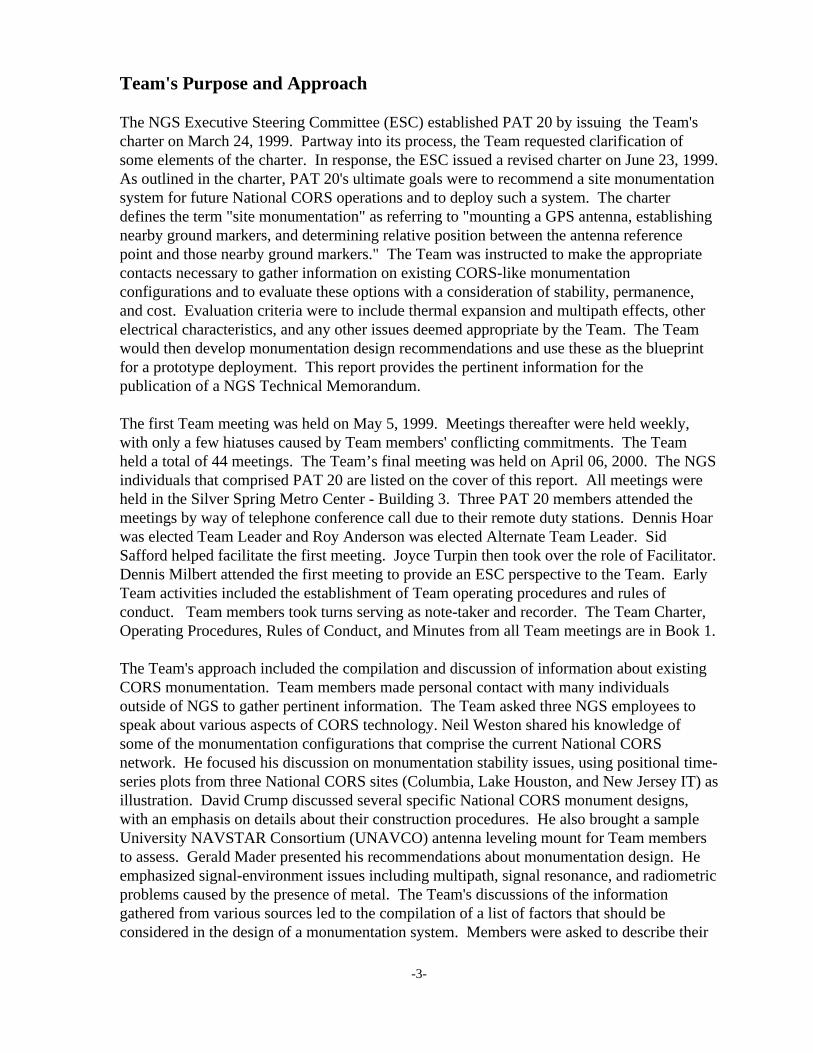
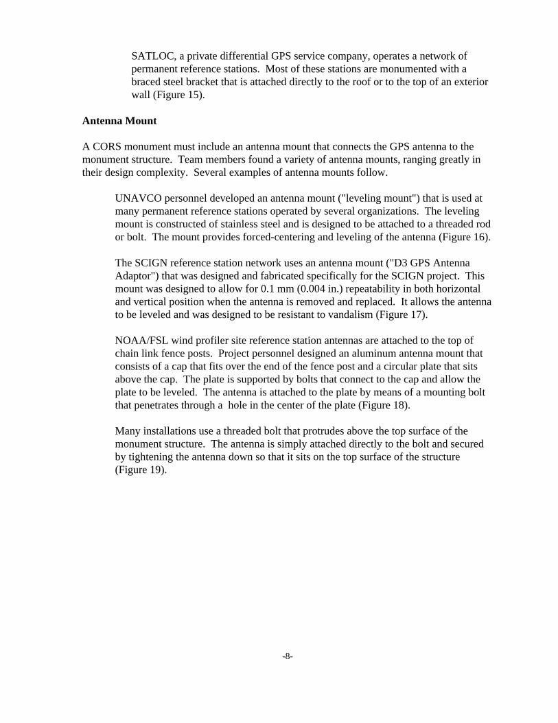
The joint UNAVCO/NGS National CORS in Platteville, Colorado, consists of arebar-reinforced, poured in place concrete pier that is 11 ft. (3.4 m) deep by 3 ft. (0.91 m) in diameter underground and 5.5 ft. (1.7 m) tall by 14 in. (0.36 m)diameter above ground. Foam insulation and PVC pipe encase the above-groundportion of the monument (Figure 1).
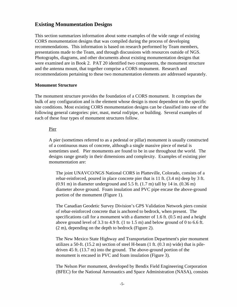
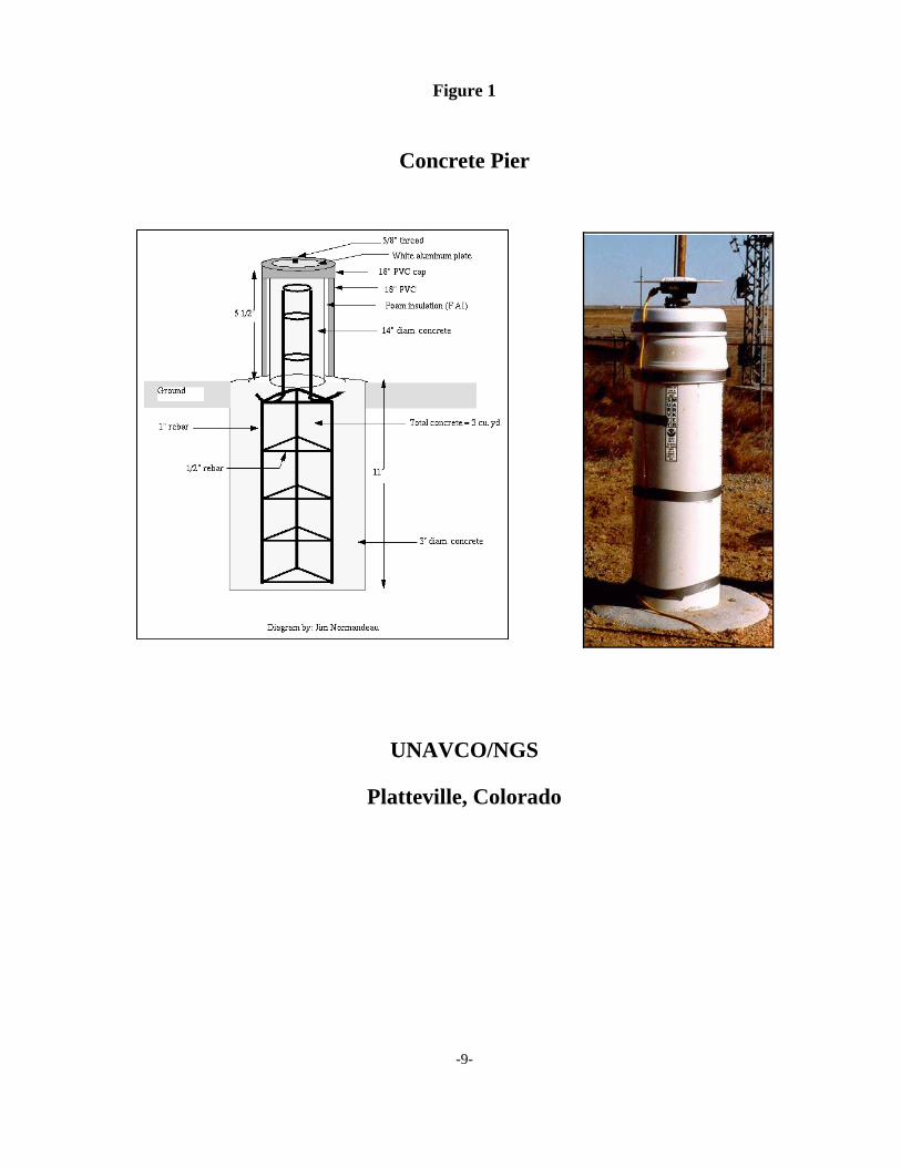
The Canadian Geodetic Survey Division’s GPS Validation Network piers consistof rebar-reinforced concrete that is anchored to bedrock, when present. Thespecifications call for a monument with a diameter of 1.6 ft. (0.5 m) and a heightabove ground level of 3.3 to 4.9 ft. (1 to 1.5 m) and below ground of 0 to 6.6 ft. (2 m), depending on the depth to bedrock (Figure 2).
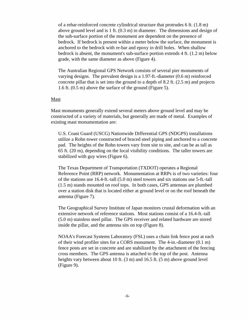
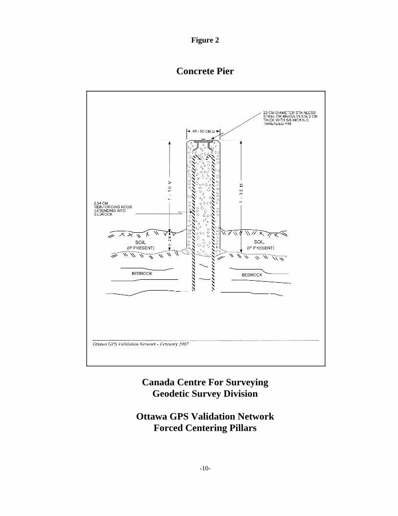
The New Mexico State Highway and Transportation Department's pier monumentutilizes a 50-ft. (15.2 m) section of steel H-beam (1 ft. (0.3 m) wide) that is pile-driven 45 ft. (13.7 m) into the ground. The above-ground portion of themonument is encased in PVC and foam insulation (Figure 3).
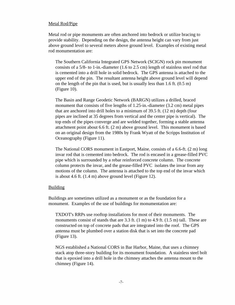
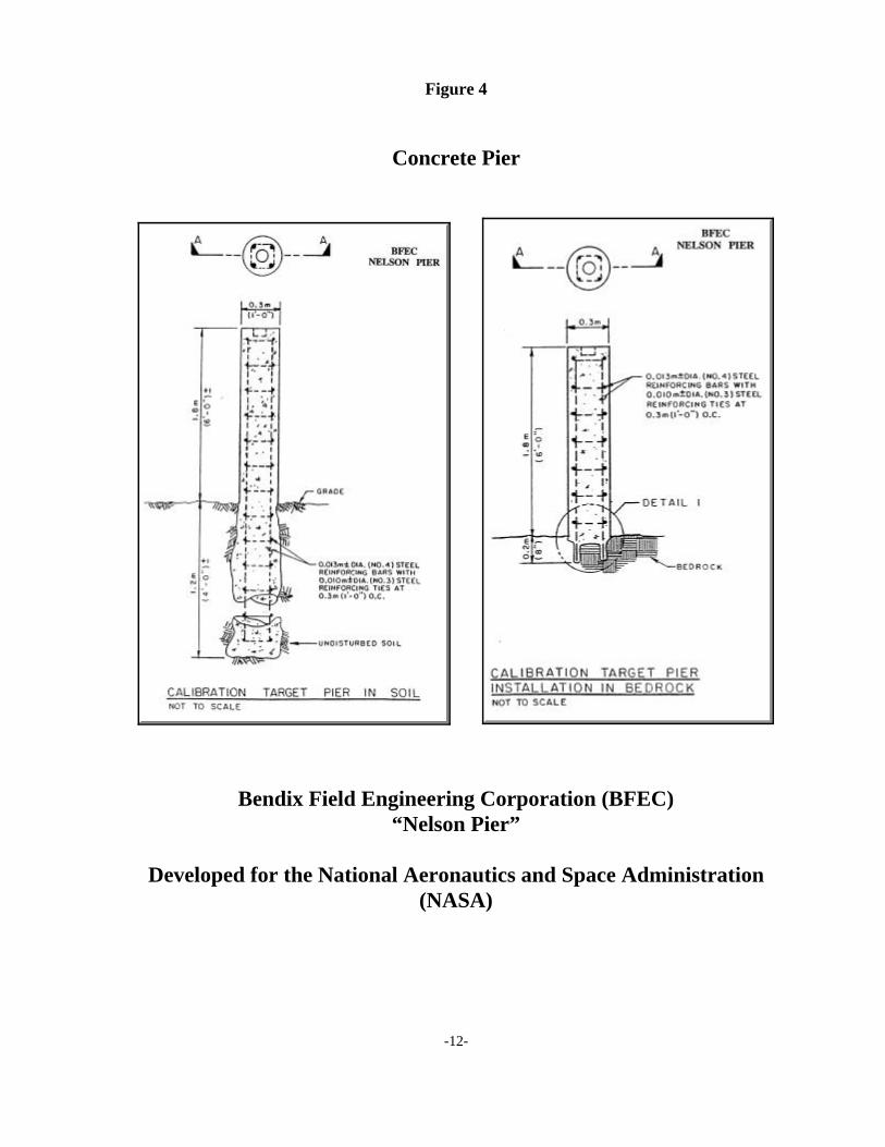
The Nelson Pier monument, developed by Bendix Field Engineering Corporation(BFEC) for the National Aeronautics and Space Administration (NASA), consists
-6-
of a rebar-reinforced concrete cylindrical structure that protrudes 6 ft. (1.8 m)above ground level and is 1 ft. (0.3 m) in diameter. The dimensions and design ofthe sub-surface portion of the monument are dependent on the presence ofbedrock. If bedrock is present within a meter below the surface, the monument isanchored to the bedrock with re-bar and epoxy in drill holes. When shallowbedrock is absent, the monument's sub-surface portion extends 4 ft. (1.2 m) belowgrade, with the same diameter as above (Figure 4).
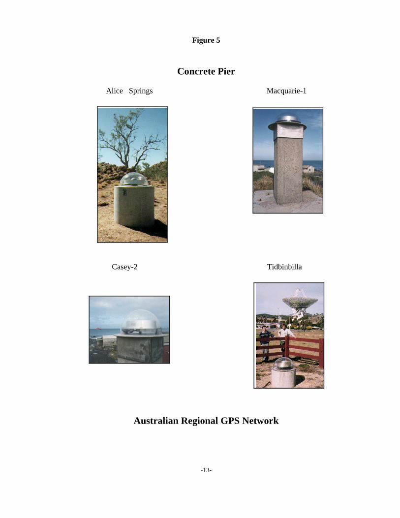
The Australian Regional GPS Network consists of several pier monuments ofvarying designs. The prevalent design is a 1.97-ft.-diameter (0.6 m) reinforcedconcrete pillar that is set into the ground to a depth of 8.2 ft. (2.5 m) and projects1.6 ft. (0.5 m) above the surface of the ground (Figure 5).
Mast
Mast monuments generally extend several meters above ground level and may beconstructed of a variety of materials, but generally are made of metal. Examples ofexisting mast monumentation are:
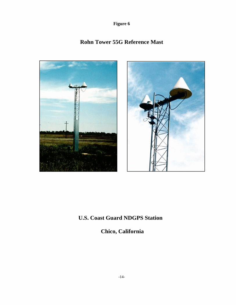
U.S. Coast Guard (USCG) Nationwide Differential GPS (NDGPS) installationsutilize a Rohn tower constructed of braced steel piping and anchored to a concretepad. The heights of the Rohn towers vary from site to site, and can be as tall as 65 ft. (20 m), depending on the local visibility conditions. The taller towers arestabilized with guy wires (Figure 6).
The Texas Department of Transportation (TXDOT) operates a RegionalReference Point (RRP) network. Monumentation at RRPs is of two varieties: fourof the stations use 16.4-ft.-tall (5.0 m) steel towers and six stations use 5-ft.-tall(1.5 m) stands mounted on roof tops. In both cases, GPS antennas are plumbedover a station disk that is located either at ground level or on the roof beneath theantenna (Figure 7).
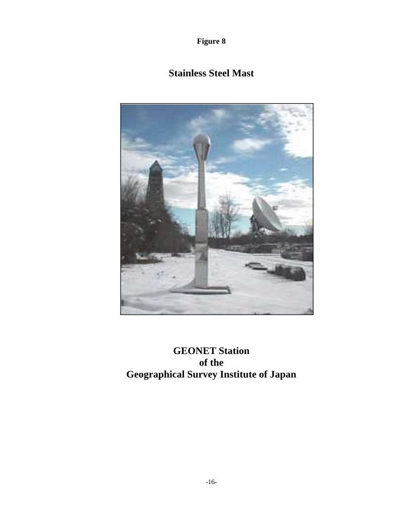
The Geographical Survey Institute of Japan monitors crustal deformation with anextensive network of reference stations. Most stations consist of a 16.4-ft.-tall(5.0 m) stainless steel pillar. The GPS receiver and related hardware are storedinside the pillar, and the antenna sits on top (Figure 8).
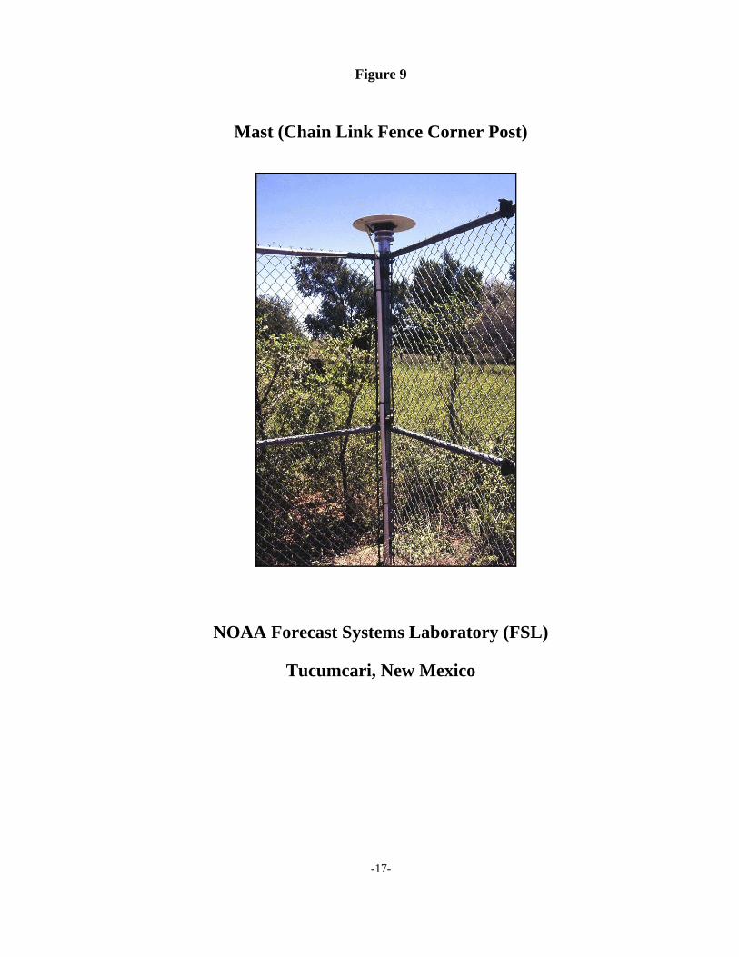
NOAA's Forecast Systems Laboratory (FSL) uses a chain link fence post at eachof their wind profiler sites for a CORS monument. The 4-in.-diameter (0.1 m)fence posts are set in concrete and are stabilized by the attachment of the fencingcross members. The GPS antenna is attached to the top of the post. Antennaheights vary between about 10 ft. (3 m) and 16.5 ft. (5 m) above ground level(Figure 9).
-7-
Metal Rod/Pipe
Metal rod or pipe monuments are often anchored into bedrock or utilize bracing toprovide stability. Depending on the design, the antenna height can vary from justabove ground level to several meters above ground level. Examples of existing metalrod monumentation are:
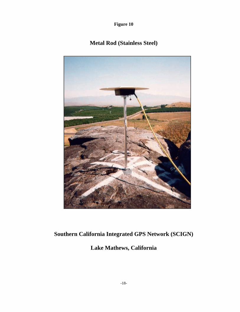
The Southern California Integrated GPS Network (SCIGN) rock pin monumentconsists of a 5/8- to 1-in.-diameter (1.6 to 2.5 cm) length of stainless steel rod thatis cemented into a drill hole in solid bedrock. The GPS antenna is attached to theupper end of the pin. The resultant antenna height above ground level will dependon the length of the pin that is used, but is usually less than 1.6 ft. (0.5 m) (Figure 10).
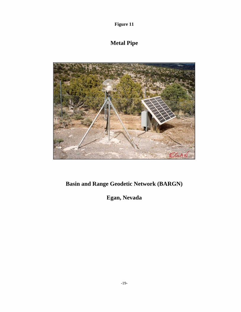
The Basin and Range Geodetic Network (BARGN) utilizes a drilled, bracedmonument that consists of five lengths of 1.25-in.-diameter (3.2 cm) metal pipesthat are anchored into drill holes to a minimum of 39.5 ft. (12 m) depth (fourpipes are inclined at 35 degrees from vertical and the center pipe is vertical). Thetop ends of the pipes converge and are welded together, forming a stable antennaattachment point about 6.6 ft. (2 m) above ground level. This monument is basedon an original design from the 1980s by Frank Wyatt of the Scripps Institution ofOceanography (Figure 11).
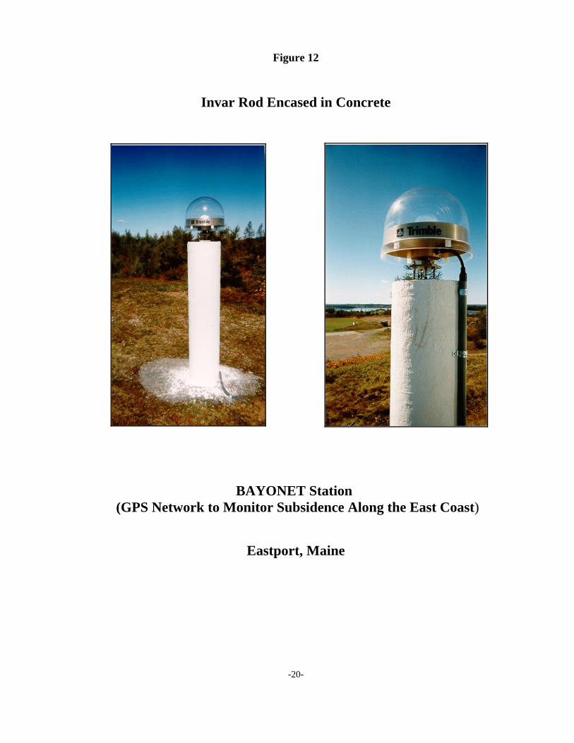
The National CORS monument in Eastport, Maine, consists of a 6.6-ft. (2 m) longinvar rod that is cemented into bedrock. The rod is encased in a grease-filled PVCpipe which is surrounded by a rebar reinforced concrete column. The concretecolumn protects the invar, and the grease-filled PVC isolates the invar from anymotions of the column. The antenna is attached to the top end of the invar whichis about 4.6 ft. (1.4 m) above ground level (Figure 12).
Building
Buildings are sometimes utilized as a monument or as the foundation for amonument. Examples of the use of buildings for monumentation are:
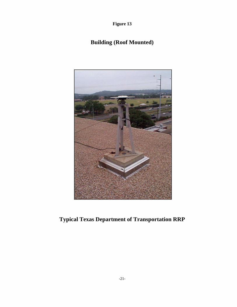
TXDOT's RRPs use rooftop installations for most of their monuments. Themonuments consist of stands that are 3.3 ft. (1 m) to 4.9 ft. (1.5 m) tall. These areconstructed on top of concrete pads that are integrated into the roof. The GPSantenna must be plumbed over a station disk that is set into the concrete pad(Figure 13).
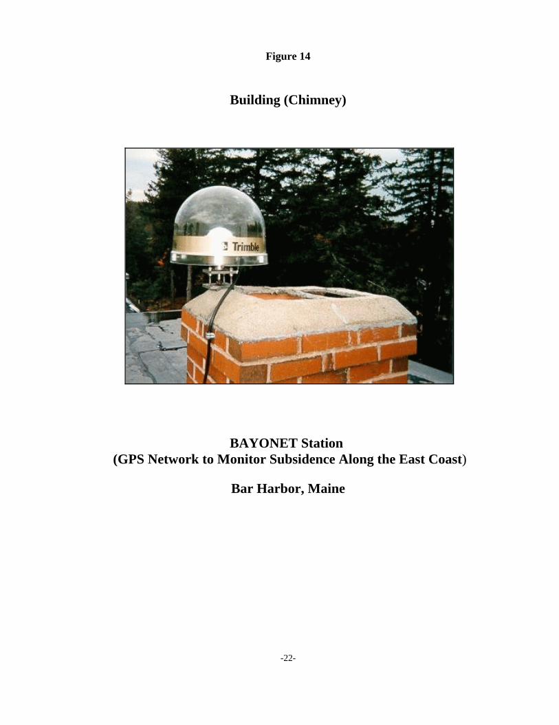
NGS established a National CORS in Bar Harbor, Maine, that uses a chimneystack atop three-story building for its monument foundation. A stainless steel boltthat is epoxied into a drill hole in the chimney attaches the antenna mount to thechimney (Figure 14).
-8-
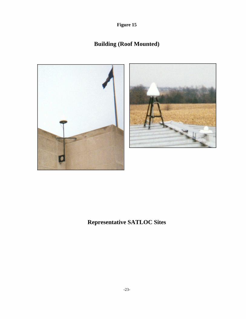
SATLOC, a private differential GPS service company, operates a network ofpermanent reference stations. Most of these stations are monumented with abraced steel bracket that is attached directly to the roof or to the top of an exteriorwall (Figure 15).
Antenna Mount
A CORS monument must include an antenna mount that connects the GPS antenna to themonument structure. Team members found a variety of antenna mounts, ranging greatly intheir design complexity. Several examples of antenna mounts follow.
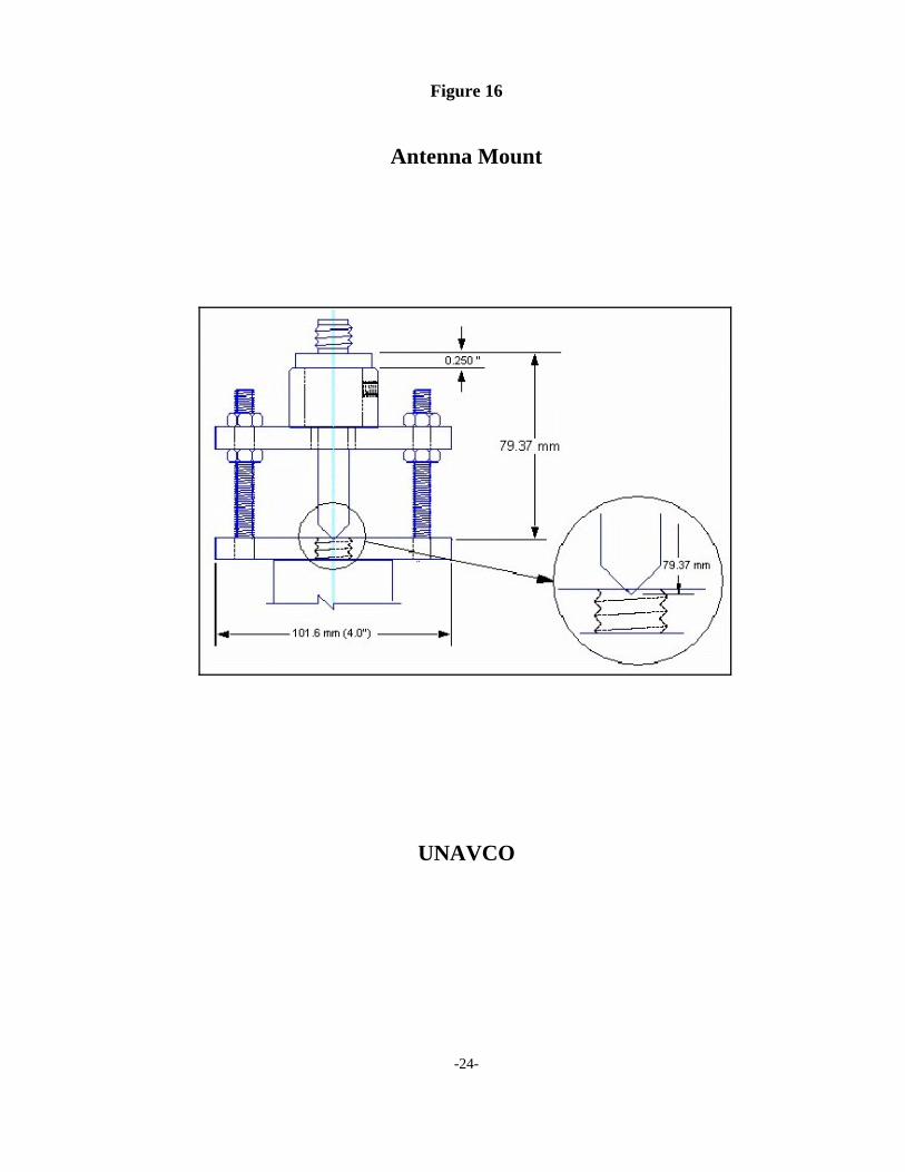
UNAVCO personnel developed an antenna mount ("leveling mount") that is used atmany permanent reference stations operated by several organizations. The levelingmount is constructed of stainless steel and is designed to be attached to a threaded rodor bolt. The mount provides forced-centering and leveling of the antenna (Figure 16).
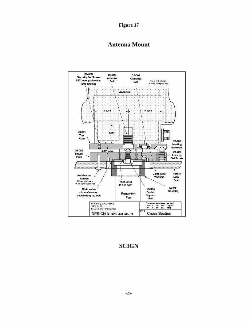
The SCIGN reference station network uses an antenna mount ("D3 GPS AntennaAdaptor") that was designed and fabricated specifically for the SCIGN project. Thismount was designed to allow for 0.1 mm (0.004 in.) repeatability in both horizontaland vertical position when the antenna is removed and replaced. It allows the antennato be leveled and was designed to be resistant to vandalism (Figure 17).
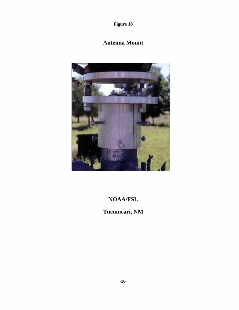
NOAA/FSL wind profiler site reference station antennas are attached to the top ofchain link fence posts. Project personnel designed an aluminum antenna mount thatconsists of a cap that fits over the end of the fence post and a circular plate that sitsabove the cap. The plate is supported by bolts that connect to the cap and allow theplate to be leveled. The antenna is attached to the plate by means of a mounting boltthat penetrates through a hole in the center of the plate (Figure 18).
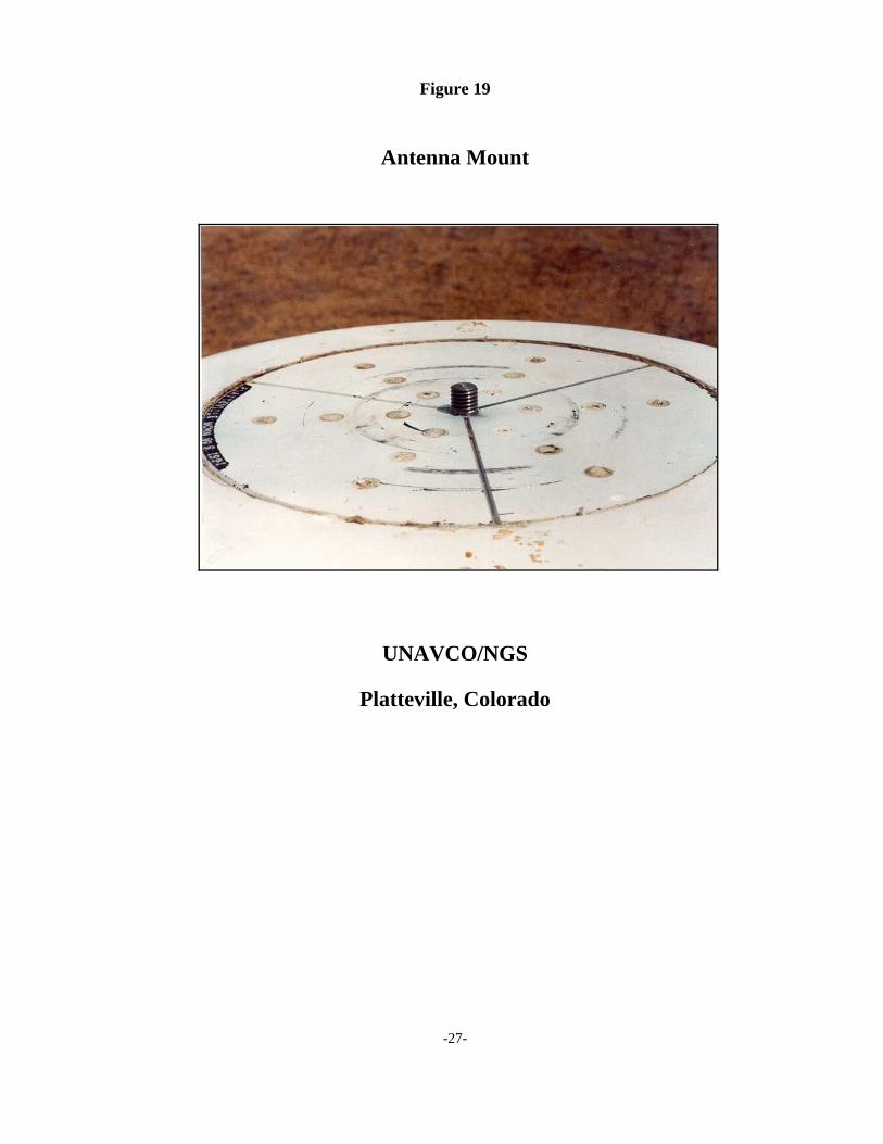
Many installations use a threaded bolt that protrudes above the top surface of themonument structure. The antenna is simply attached directly to the bolt and securedby tightening the antenna down so that it sits on the top surface of the structure(Figure 19).
-9-
Figure 1
Concrete Pier
UNAVCO/NGS
Platteville, Colorado
-10-
Figure 2
Concrete Pier
Canada Centre For SurveyingGeodetic Survey Division
Ottawa GPS Validation NetworkForced Centering Pillars
-11-
Figure 3
H-Beam Pier
New Mexico State Highwayand
Transportation Department
Albuquerque, New Mexico
-12-
Figure 4
Concrete Pier
Bendix Field Engineering Corporation (BFEC)“Nelson Pier”
Developed for the National Aeronautics and Space Administration(NASA)
-13-
Figure 5
Concrete Pier
Alice Springs Macquarie-1
Casey-2 Tidbinbilla
Australian Regional GPS Network
-14-
Figure 6
Rohn Tower 55G Reference Mast
U.S. Coast Guard NDGPS Station
Chico, California

-15-
Figure 7
Steel Mast
Texas Department of Transportation (RRP)
Austin, Texas
-16-
Figure 8
Stainless Steel Mast
GEONET Stationof the
Geographical Survey Institute of Japan
-17-
Figure 9
Mast (Chain Link Fence Corner Post)
NOAA Forecast Systems Laboratory (FSL)
Tucumcari, New Mexico
-18-
Figure 10
Metal Rod (Stainless Steel)
Southern California Integrated GPS Network (SCIGN)
Lake Mathews, California
-19-
Figure 11
Metal Pipe
Basin and Range Geodetic Network (BARGN)
Egan, Nevada
-20-
Figure 12
Invar Rod Encased in Concrete
BAYONET Station (GPS Network to Monitor Subsidence Along the East Coast)
Eastport, Maine
-21-
Figure 13
Building (Roof Mounted)
Typical Texas Department of Transportation RRP
-22-
Figure 14
Building (Chimney)
BAYONET Station (GPS Network to Monitor Subsidence Along the East Coast)
Bar Harbor, Maine
-23-
Figure 15
Building (Roof Mounted)
Representative SATLOC Sites
-24-
Figure 16
Antenna Mount
UNAVCO
-25-
Figure 17
Antenna Mount
SCIGN
-26-
Figure 18
Antenna Mount
NOAA/FSL
Tucumcari, NM
-27-
Figure 19
Antenna Mount
UNAVCO/NGS
Platteville, Colorado
-28-
Monumentation Design Issues
As the Team examined existing monumentation scenarios and worked towards developing aset of design recommendations, several pertinent issues were identified, researched, anddiscussed. These issues are: GPS signal-related effects, physical site conditions, monumentconstruction materials, antenna mounting requirements, and other miscellaneous issues. Thissection summarizes these issues and their impact on the Team’s recommendations.
GPS Signal Issues
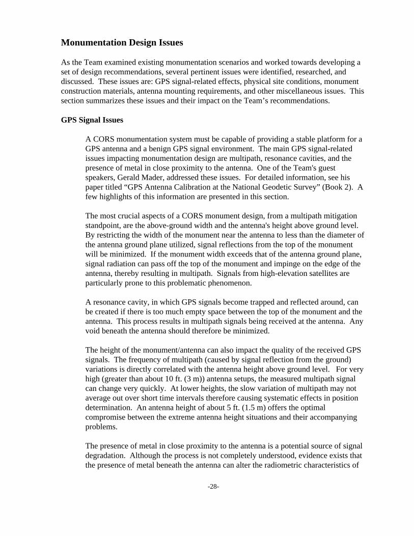
A CORS monumentation system must be capable of providing a stable platform for aGPS antenna and a benign GPS signal environment. The main GPS signal-relatedissues impacting monumentation design are multipath, resonance cavities, and thepresence of metal in close proximity to the antenna. One of the Team's guestspeakers, Gerald Mader, addressed these issues. For detailed information, see hispaper titled “GPS Antenna Calibration at the National Geodetic Survey” (Book 2). Afew highlights of this information are presented in this section.
The most crucial aspects of a CORS monument design, from a multipath mitigationstandpoint, are the above-ground width and the antenna's height above ground level. By restricting the width of the monument near the antenna to less than the diameter ofthe antenna ground plane utilized, signal reflections from the top of the monumentwill be minimized. If the monument width exceeds that of the antenna ground plane,signal radiation can pass off the top of the monument and impinge on the edge of theantenna, thereby resulting in multipath. Signals from high-elevation satellites areparticularly prone to this problematic phenomenon.
A resonance cavity, in which GPS signals become trapped and reflected around, canbe created if there is too much empty space between the top of the monument and theantenna. This process results in multipath signals being received at the antenna. Anyvoid beneath the antenna should therefore be minimized.
The height of the monument/antenna can also impact the quality of the received GPSsignals. The frequency of multipath (caused by signal reflection from the ground)variations is directly correlated with the antenna height above ground level. For veryhigh (greater than about 10 ft. (3 m)) antenna setups, the measured multipath signalcan change very quickly. At lower heights, the slow variation of multipath may notaverage out over short time intervals therefore causing systematic effects in positiondetermination. An antenna height of about 5 ft. (1.5 m) offers the optimalcompromise between the extreme antenna height situations and their accompanyingproblems.
The presence of metal in close proximity to the antenna is a potential source of signaldegradation. Although the process is not completely understood, evidence exists thatthe presence of metal beneath the antenna can alter the radiometric characteristics of

-29-
the antenna. The amount of metal used in a monument should be kept at a minimumto avoid this potential problem.
Site Issues
For any CORS installation, the most appropriate type of monumentation will bepartially dictated by the physical site conditions. These conditions include the soiltype, presence of bedrock, water table level, frost penetration depth, nearbyobstructions, and climate. Since these conditions can vary greatly from site to site, itis impossible to design a CORS monument that is optimal for all sites. Most concernsabout the subsurface character of the site can be adequately addressed by designing amonument that is of sufficient breadth and depth that it provides the required stability. Proper depth of a monument will anchor it to a level that is unaffected by frost actionand that is free of near-surface soil motion and instability. The depth of the watertable can impact the choice of design but is not an overriding factor in most areas. Whenever a monument can be attached to solid bedrock, an extremely stablemonument foundation will result. The use of bedrock probably provides the ultimatein monument stability potential.
The presence of nearby obstructions will dictate the monument height required toprovide adequate sky visibility to incoming satellite signals. In cases where a very tallmonument is required in order to avoid obstructions, some CORS performancecharacteristics, such as multipath-mitigation and positional stability, might becompromised. Tradeoffs such as these are sometimes unavoidable.
The local climate can also be a factor that impacts the monument's design. In heavysnowfall areas, the monument must be tall enough so that the antenna is not buriedbeneath accumulated snow. In areas with large temperature fluctuations, the thermalexpansion of materials might be of such a magnitude that it must be considered whenselecting the proper monument design.
Construction Material Issues
In developing a set of monumentation recommendations, various aspects of theconstruction materials and installation procedure must be considered. Althoughpositional stability and a benign signal environment are of prime importance, a CORSmonument should also be affordable and relatively easy to install. The constructionmaterials should be easy to procure, and any components should be available off-the-shelf whenever possible. The design and materials should produce a monument witha good likelihood of surviving for many years.
CORS monuments are continuously subjected to the elements, and any materials usedshould be able to withstand the exposure (sun exposure, precipitation, temperaturevariations, corrosive soil conditions, etc.). Most materials are not completely immuneto the damaging affects of these processes, but some will survive better than others.
-30-
Depending on the size and shape of a monument, thermal expansion can be animportant design consideration. Thermal expansion of materials can impact both thescale and shape of a structure, thereby changing a monument's height and/or position.The taller a monument is, the more prone it is to these changes. Changes in astructure's shape occur when differential heating, caused by partial sun-shading,results in varying amounts of expansion throughout the structure. Concrete and steelhave comparable coefficients of expansion (approximately 6 parts per million perdegree Fahrenheit). For instance, a structure that is 33 ft. (10 m) tall and is exposed toan inter-seasonal temperature change of 100 degrees F (56 C) will change in length byabout 0.24 in. (6 mm). For a concrete or steel monument that is about 6.6 ft. (2 m)tall, the same temperature change scenario will result in a change of only 0.004 in.(1 mm). See Book 2 for additional information on the thermal expansion propertiesof several materials.
Whenever metal is placed in an environment that includes moisture, salts, andoxygen, electrolysis can occur. A combination of dissimilar metals is particularlyvulnerable to this process. The corrosive effects of electrolysis can compromise theintegrity of a structure, and steps should be taken to prevent this process. By selectingthe proper types of metal for specific site conditions and by avoiding the juxtapositionof dissimilar metals, electrolysis can be rendered a non-issue in most instances.
Many different construction materials could conceivably be used in a CORSmonument. These include various types of metals (e.g., stainless steel, galvanizedsteel, aluminum, invar), concrete, stone, wood, and others. Each candidate materialhas advantages and disadvantages regarding its suitability for use in a CORSmonument. The selection of an optimal design and set of materials must include aconsideration of these issues.
Antenna Mounting Issues
Several considerations impact the design of a CORS monument antenna mount. Itmust provide forced-centering, thereby locating the antenna at a repeatable horizontalposition, even when the antenna is removed and reattached or replaced. It shouldprovide a stable and level surface upon which the base of the antenna sits, therebyensuring a repeatable antenna reference point height. The mount should allow theantenna to be oriented to true north, as required for proper baseline processing andusage of antenna phase models. To preserve the inherent radiometric characteristicsof the antenna, the amount of metal directly contacting the antenna should beminimized.
-31-
Miscellaneous Issues
There are many other issues that play a role in the overall design of a CORS facility. These additional issues include aspects such as data characteristics (format,availability, quality control, reliability, transmission), peripheral utilities/hardware(power, telephone, on-site computer, backup power source), security, and others. TheTeam felt that its mandated focus on details pertaining to developing amonumentation system eliminated most of these additional concerns from the scopeof this group. National CORS site selection information can be found in thedocument "National Geodetic Survey CORS System: Station Selection Criteria”,dated February 1, 1999 (Book 2).
-32-
Recommendations
The Team determined that it is impossible to generate a CORS monument design that isappropriate for all types of site conditions and configurations. The recommendationseventually adopted by the Team, and presented here, were deemed to be appropriate for thewidest range of situations that are likely to be met. There are some CORS installations thatwill require either a modification of the proposed design or, in some instances, a completelydifferent approach.
The two basic elements that comprise a monument are the monument structure (thecomponent that provides the physical support, stability, and connection to the surface of theearth) and the antenna mount (the component that allows the antenna to be physicallyconnected to the monument structure). The Team worked on designing these two elementsseparately, keeping in mind that they would eventually need to be joined together for the finalconfiguration.
Monument Structure
PAT 20 recommends a poured-in-place concrete pier monument for most futureNational CORS installations. Concrete piers are in use by various organizations, andthe Team feels that this is the optimal general-purpose design. The Team's researchindicated that a properly designed concrete pier monument will provide a high levelof positional stability as well as a relatively benign signal environment. In addition,this type of monument is straightforward and relatively inexpensive to install. Theimportant design characteristics of a pier monument were identified as the shape,depth, height, diameter, type of concrete, presence of reinforcement material, andinstallation procedure.
To provide good stability, the majority of the structure's concrete should be located inthe below ground portion of the structure. The Team recommends a step-tieredcylindrical design in which the diameter and the depth of the sub-surface portion aregreater than the diameter and the height of the above-surface portion. The transitionbetween the two profiles takes place at ground level. For the sub-surface portion ofthe monument, the Team decided on a poured-in-place design utilizing an augeredhole. The connection between the monument and the surrounding soil is likely to begreater with this kind of design than it would be if a form were utilized for theinstallation. In order to mitigate signal multipath, the diameter of the above-surfacestructure was chosen so that it is less than the diameter of most GPS antennas thatmight be mounted on the monument. To provide for structural continuity betweenthe sub-surface and above-surface portions, the concrete should be poured in onesession. A cylindrical construction form (such as a Sonotube), held in place by atemporary support, can be used when the concrete is poured for the above groundportion of the monument. The Sonotube can be removed once the concrete hassufficiently hardened.
-33-
The monument dimensions decided upon are: a minimum depth of 10 ft. (3.0 m) by aminimum diameter of 1.5 ft.. (0.46 m) for the sub-surface portion and a height of 5 ft. (1.5 m) by a diameter of 1 ft. (0.3 m) for the above-surface portion. The minimumdepth of 10 ft. (3.0 m) provides for an adequate mass of concrete, attachment to soilthat is not influenced by frost penetration, and isolation from near-surface soilinstabilities. This depth allows the monument to be classified with "B" stability("monuments which generally hold their elevations fairly well") as documented in theNGS publication "Input Formats and Specifications of the National Geodetic SurveyData Base, Volume I. Horizontal Control Data." The above-surface diameter of 1 ft.(0.3 m) is less than that of most GPS antenna ground planes, thereby minimizingsignal reflections from the top of the monument but still providing adequate stabilityand structural strength. The height of 5 ft. (1.5 m) places the antenna in the realm ofwhat is believed to be an optimal distance above ground, from a multipath-mitigationstandpoint. This height is very close to the configuration that is used in the antennaphase-center modeling work that has been performed by NGS. This similarity insignal environment is an important contributor to the success of the models forsubsequent data reduction. The height of 5 ft. (1.5 m) will also facilitate the use ofdifferential leveling to establish an orthometric height for the monument. A ratio of2:1 of the depth-to-height provides good stability, with the monument's center of masslocated well beneath the mid-point of the structure.
Having determined the dimensional characteristics of the monument, the Teamaddressed the type of concrete that would be used and whether the structure shouldinclude any kind of reinforcement within the concrete. Pertinent issues pertaining tosome fundamentals of concrete are presented in Book 2. By examining thisinformation and discussing requirements with concrete professionals, the Teamdecided that Type IIIA portland cement and 3/4- to 1-1/2-in. aggregate would have theappropriate strength, thermal expansion, and curing characteristics for a monumentstructure.
Concrete has high compressive strength but, by itself, has limited tensile and shear strength. To provide additional structural integrity, the Team decided thatreinforcement material should be included within the concrete. The main purpose ofthe reinforcement is to provide the structure with shear strength at ground level wherethe monument diameter steps from 1.5 ft. (0.46 m) to 1 ft. (0.3 m). Due to theconcerns about minimizing the amount of metal in close proximity to the GPSantenna, the Team felt that traditional rebar should be avoided. Marshall IndustriesComposites, Inc., produces a structural reinforcing material called C-Bar (See Book 2for information about C-Bar). It is available in various size rods and is designedspecifically as a non-metallic alternative to traditional rebar for concrete applicationsin which metal should be avoided. A reinforcement rod assembly constructed of C-Bar and embedded in the concrete at the time of construction will provide thereinforcement value of traditional rebar without compromising the GPS signalenvironment. The Team believes that the inclusion of C-Bar into the design is a low-
-34-
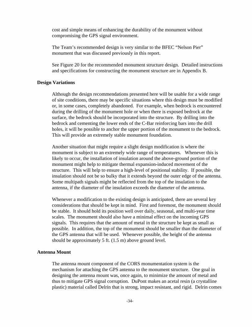
cost and simple means of enhancing the durability of the monument withoutcompromising the GPS signal environment.
The Team’s recommended design is very similar to the BFEC “Nelson Pier”monument that was discussed previously in this report.
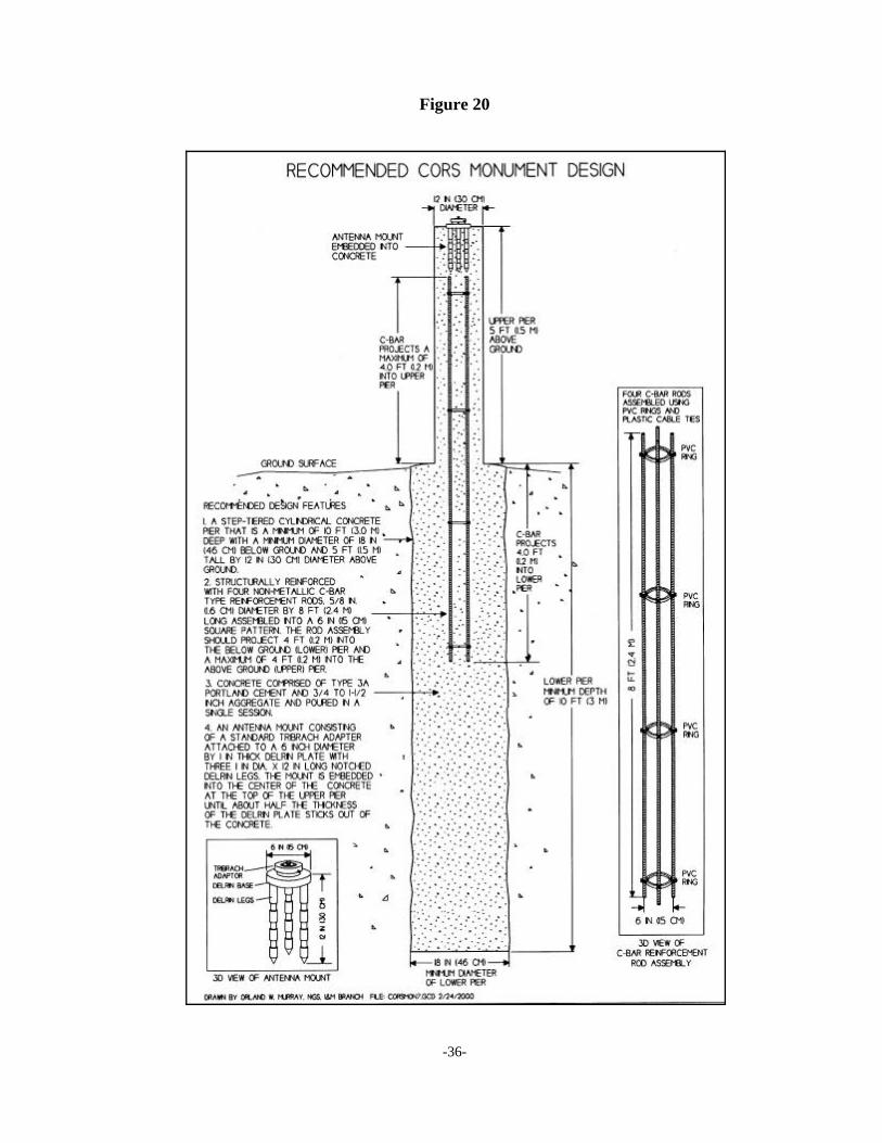
See Figure 20 for the recommended monument structure design. Detailed instructionsand specifications for constructing the monument structure are in Appendix B.
Design Variations
Although the design recommendations presented here will be usable for a wide rangeof site conditions, there may be specific situations where this design must be modifiedor, in some cases, completely abandoned. For example, when bedrock is encounteredduring the drilling of the monument hole or when there is exposed bedrock at thesurface, the bedrock should be incorporated into the structure. By drilling into thebedrock and cementing the lower ends of the C-Bar reinforcing bars into the drillholes, it will be possible to anchor the upper portion of the monument to the bedrock. This will provide an extremely stable monument foundation.
Another situation that might require a slight design modification is where themonument is subject to an extremely wide range of temperatures. Whenever this islikely to occur, the installation of insulation around the above-ground portion of themonument might help to mitigate thermal expansion-induced movement of thestructure. This will help to ensure a high-level of positional stability. If possible, theinsulation should not be so bulky that it extends beyond the outer edge of the antenna. Some multipath signals might be reflected from the top of the insulation to theantenna, if the diameter of the insulation exceeds the diameter of the antenna.
Whenever a modification to the existing design is anticipated, there are several keyconsiderations that should be kept in mind. First and foremost, the monument shouldbe stable. It should hold its position well over daily, seasonal, and multi-year timescales. The monument should also have a minimal effect on the incoming GPSsignals. This requires that the amount of metal in the structure be kept as small aspossible. In addition, the top of the monument should be smaller than the diameter ofthe GPS antenna that will be used. Whenever possible, the height of the antennashould be approximately 5 ft. (1.5 m) above ground level.
Antenna Mount
The antenna mount component of the CORS monumentation system is themechanism for attaching the GPS antenna to the monument structure. One goal indesigning the antenna mount was, once again, to minimize the amount of metal andthus to mitigate GPS signal corruption. DuPont makes an acetal resin (a crystallineplastic) material called Delrin that is strong, impact resistant, and rigid. Delrin comes
-35-
in a variety of shapes and stocks and is machinable. It can be used as an alternative tomany kinds of metal in situations where the presence of metal is problematic. SeeBook 2 for additional information about Delrin.
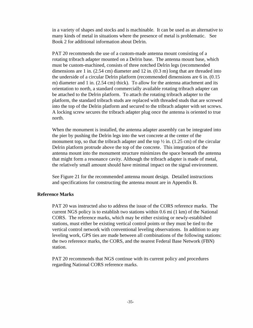
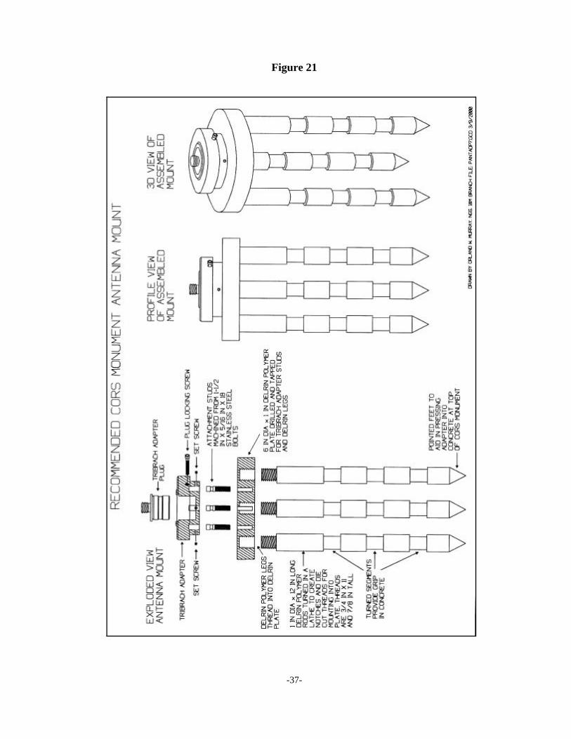
PAT 20 recommends the use of a custom-made antenna mount consisting of arotating tribrach adapter mounted on a Delrin base. The antenna mount base, whichmust be custom-machined, consists of three notched Delrin legs (recommendeddimensions are 1 in. (2.54 cm) diameter and 12 in. (0.3 m) long that are threaded intothe underside of a circular Delrin platform (recommended dimensions are 6 in. (0.15m) diameter and 1 in. (2.54 cm) thick). To allow for the antenna attachment and itsorientation to north, a standard commercially available rotating tribrach adapter canbe attached to the Delrin platform. To attach the rotating tribrach adapter to theplatform, the standard tribrach studs are replaced with threaded studs that are screwedinto the top of the Delrin platform and secured to the tribrach adapter with set screws. A locking screw secures the tribrach adapter plug once the antenna is oriented to truenorth.
When the monument is installed, the antenna adapter assembly can be integrated intothe pier by pushing the Delrin legs into the wet concrete at the center of themonument top, so that the tribrach adapter and the top ½ in. (1.25 cm) of the circularDelrin platform protrude above the top of the concrete. This integration of theantenna mount into the monument structure minimizes the space beneath the antennathat might form a resonance cavity. Although the tribrach adapter is made of metal,the relatively small amount should have minimal impact on the signal environment.
See Figure 21 for the recommended antenna mount design. Detailed instructionsand specifications for constructing the antenna mount are in Appendix B.
Reference Marks
PAT 20 was instructed also to address the issue of the CORS reference marks. Thecurrent NGS policy is to establish two stations within 0.6 mi (1 km) of the NationalCORS. The reference marks, which may be either existing or newly-establishedstations, must either be existing vertical control points or they must be tied to thevertical control network with conventional leveling observations. In addition to anyleveling work, GPS ties are made between all combinations of the following stations:the two reference marks, the CORS, and the nearest Federal Base Network (FBN)station.
PAT 20 recommends that NGS continue with its current policy and proceduresregarding National CORS reference marks.
-36-
Figure 20
-37-
Figure 21
-38-
Prototype Monument Installation
On November 23-24, 1999, several members of PAT 20, with the assistance of NGSpersonnel from the Instrumentation and Methodologies Branch, installed a prototype CORSmonument at the NGS facility in Corbin, Virginia. This prototype is based on the designrecommendations developed by PAT 20 and presented in this report. The only differencebetween the recommended design and the prototype design is in the concrete reinforcementassembly. The recommendations specify an assembly that is 8 ft. (2.4 m) in length andconstructed from C-Bar reinforcement rods. When the prototype components were beingfabricated, 5-ft.-long (1.5 m) rods made of Delrin (the same material used for the antennamount base) were used to make the reinforcement assembly. Although the Delrin assemblywill provide the desired reinforcement to the concrete structure, C-Bar is more specificallydesigned for this kind of application. A 21-in. (0.53 m) diameter auger was used to drill thehole for the prototype monument. The dimensions of the resultant hole were 22 in. (0.56 m)diameter by 11 ft. 4 in. (3.45 m) deep. Both of these dimensions exceed the nominal valuesspecified in the recommendations. The total cost of materials and services for the prototypemonument installation was $688.80. The labor involved in installing the monumentamounted to about 24 staff-hours on the part of NGS employees.
Detailed information on the prototype construction procedures, itemized cost, and an as builtdrawing are included in the “Report on the Installation of the National CORS PrototypeMonument” (Appendix A).
-39-
Conclusion
PAT 20 has examined many examples of existing CORS monuments, identified, andexamined the important issues that impact the design of a monument, developedrecommendations for a monumentation system design, and installed a prototype monumentbased on the recommendations.
PAT 20 recommends the following National CORS monument design: a step-tieredcylindrical concrete pier that is a minimum depth of 10 ft. (3.0 m) by a minimum diameter of1.5 ft. (0.46 m) below ground level and a height of 5 ft. (1.5 m) by a diameter of 1 ft. (0.3 m)above ground, with an antenna mount consisting of a rotating tribrach adapter attached to anon-metallic base that is integrated into the concrete pier.
The Team believes that this design will be suitable for a wide range of site conditions andshould provide the high level of horizontal and vertical stability required for National CORSapplications. This kind of monument has an excellent chance for long term survivability. Themonument materials (concrete, C-Bar reinforcement rods, Delrin stock, and tribrach adapter)are readily available and affordable. The preparation of materials and installation procedureare relatively straightforward and require only a limited amount of specialized equipment andtechnique. The diameter and height of the monument, along with the minimal amount ofmetal involved, provide a benign GPS signal environment. The antenna can be locked in atrue north orientation and will be force-centered to a repeatable position whenever it isremoved and replaced.
PAT 20 recommends that NGS continue with its current policy and procedures regarding theestablishment of National CORS reference marks.