National Fire Protection Association on Proposals – June 2013 NFPA 70 _____ 11-1 Log #1170j...
58
National Fire Protection Association 1 Batterymarch Park, Quincy, MA 02169-7471 Phone: 617-770-3000 • Fax: 617-770-0700 • www.nfpa.org AGENDA NEC Code-Making Panel 11 Report on Proposal Meeting January 9 – 11, 2012 Hilton Head, SC Item No. Subject 12-1 -1 Call to Order 12-1-2 Introduction of Members and Guests 12-1-3 Review of Meeting Procedures and Revision Schedule 12-1-4 Comments/Questions from Committee Members and/or Guests 12-1-5 Task Group Reports (if any) 12-1-6 Processing of Proposals 12-1-7 Fire Protection Research Foundation Requests 12-1-8 Old Business 12-1-9 New Business 12-1-10 Adjournment
Transcript of National Fire Protection Association on Proposals – June 2013 NFPA 70 _____ 11-1 Log #1170j...

National Fire Protection Association 1 Bat terymarch Park, Quincy, MA 02169-7471 Phone: 617-770-3000 • Fax: 617-770-0700 • www.nfpa.org
AGENDA
NEC Code-Making Panel 11
Report on Proposal Meeting
January 9 – 11, 2012
Hilton Head, SC
Item No. Subject 12-1 -1 Call to Order 12-1-2 Introduction of Members and Guests 12-1-3 Review of Meeting Procedures and Revision Schedule 12-1-4 Comments/Questions from Committee Members and/or Guests 12-1-5 Task Group Reports (if any) 12-1-6 Processing of Proposals 12-1-7 Fire Protection Research Foundation Requests 12-1-8 Old Business 12-1-9 New Business 12-1-10 Adjournment

Chair Report 11/25/2011
Log Proposal No. Code Reference Log Proposal No. Code Reference
1170j Entire Document11-1
921j Entire Document11-2
1492 100.Adjustable-Speed Drive11-3
1601 100.Adjustable-Speed Drive11-4
1480 100.Control Circuit (New) and11-5
1603 100.Hermetic Refrigerant11-6
1481 100.Industrial Control Panel11-7
1602 100.Motor Control Circuit11-8
3302 409, 430, 440, 460, and 47011-9
991 409.111-10
2638c 409.1 and 409.110(4),11-11
1212 409.2. Industrial Control Panel11-12
792 409.2011-13
3322 409.70 (New)11-14
362 409.10611-15
2253 409.110(2)11-16
3215 409.110(3)11-17
3236 409.110(8) (New)11-18
183 43011-19
1033 430, Parts I through X11-20
1771 430.211-21
1217 430.2. Adjustable-Speed Drive11-22
762 430.2. Motor Circuit Protector11-23
1763 430.2. Motor Circuit Protector11-24
50 430.2.Valve Actuator Motor11-25
2492 Table 430.511-26
101 430.6(A)(1) Exception No. 411-27
1668 430.8 and 430.98(A)11-28
1157 430.1311-29
3090 430.22(G)11-30
1787 430.2711-31
2538 430.27 (New)11-32
2337 430.31, Part III11-33
1656 430.5211-34
2338 430.52(B)11-35
111 430.52(C)(7)11-36
1764 430.6211-37
2310 430.62(A)11-38
865 430.75(A) Exception No. 1(b)11-39
2257 430.75(B)11-40
51 430.81(C) and Informational11-41
3323 430.92 (New)11-42
361 Table 430.97(D)11-43
2258 430.101(A)11-44
291 430.102 Exception No. 111-45
866 430.102(A) Exception No. 111-46
477 430.102(A) Exception No. 3(b)11-47
292 430.102(A) Exception No. 3 (b)11-48
293 430.102(B) Exception to (1)11-49
478 430.102(B) Exception to (1)11-50
1873 430.102(B)(2), Informational11-51
692 430.102(B)(2) Exception (b)11-52
867 430.11311-53
294 430.113 Exception No. 111-54
3324 430.121 (New)11-55
104 430.12311-56
2322 430.126(A)11-57
184 430.126(A)(2)11-58
3091 430.12811-59
2642 430.128 Exception (New)11-60
1032 430, Part XI11-61
2793 430.22311-62
2826 430.223 and 430.24511-63
295 430.22711-64
3356 430.228 (New)11-65
841 430.23211-66
842 430.23311-67
843 430.23311-68
1963 430.241, Informational Note11-69
1814 430.245(B)11-70
2040 430.245(B)11-71
2369 430.245(B)11-72
2397 430.245(B)11-73
2852 430.245(B)11-74
781 440.2.Adjustable Speed Drive,11-75
1218 440.2.Branch-Circuit Selection11-76
2493 Table 440.3(D)11-77
782 440.411-78
1669 440.5 and 440.6011-79
783 440.5 Exception (New)11-80
784 440.6(C)11-81
785 440.7 Exception No. 2 (New)11-82
1622 440.911-83
3325 440.9 (New)11-84
786 440.1211-85
296 440.14 Exception No. 111-86
479 440.14 Exception No. 111-87
787 440.2211-88
1

Chair Report 11/25/2011
Log Proposal No. Code Reference Log Proposal No. Code Reference
788 440.37 (New)11-89
789 440.4111-90
790 440.5211-91
148 460.2(A) and (B)11-92
1035 460, Part I11-93
1036 460, Part II11-94
868 460.24(B)(2)11-95
1037 470, Part I11-96
115 470.211-97
1038 470, Part II11-98
2

Report on Proposals – June 2013 NFPA 70_______________________________________________________________________________________________11-1 Log #1170j NEC-P11
_______________________________________________________________________________________________Russell LeBlanc, The Peterson School
In articles 90 through 830, if the wording is not already there, then add the words (or otherstructure(s)) after the word BUILDING(S) wherever the intent of the requirement is to also include STRUCTURES aswell as buildings.
There is a flaw in the NEC. The term "building" is used over 1000 times in the NEC, and in most of thecases the words "or other structure" should follow and apply the same requirements to bridges, billboards, towers,tanks, and other structures that are by definition NOT BUILDINGS. One specific example I can use is section 225.10Wiring onBuildings. I believe that this section is also intended to be applied structures, but the wording "or other structures" is notin the heading or the paragraph. There are literally thousands of other instances throughout the code that this sameproblem exists. This can easily be seen by doing an electronic search for the word "building". In some cases the words"or other structure" (or similar wording) are present, but in the vast majority where the requirements should also beapplied to structures other than buildings, the wording is not there.
_______________________________________________________________________________________________11-2 Log #921j NEC-P11
_______________________________________________________________________________________________Joe Tedesco, Boston, MA
The term "adequate" and "adequately" and "inadequately" and "inadequate" should be replacedwith terms that can be properly enforced and understood.
Terms are not defined and are considered vague and unenforceable per Table 3.2.1 in the NEC StyleManaual. They are all "incorrect" 148 times in the NEC.
_______________________________________________________________________________________________11-3 Log #1492 NEC-P11
_______________________________________________________________________________________________James F. Williams, Fairmont, WV
Revise text to read as follows:
An interconnected combination of equipment that provides a means of adjusting thespeed of a mechanical load coupled to a motor. A drive system typically consists of an adjustable speed drive andauxiliary electrical apparatus.
An interconnected combination of equipment that provides a means of adjusting thespeed of a mechanical load coupled to a motor. A drive system typically consists of an adjustable speed drive andauxiliary electrical apparatus.
The defined term is referenced in several articles of the NEC: , , ,.
In general, Article 100 shall contain definitions of terms that appear in two ormore other articles of the .
1Printed on 11/25/2011

Report on Proposals – June 2013 NFPA 70_______________________________________________________________________________________________11-4 Log #1601 NEC-P11
_______________________________________________________________________________________________James F. Williams, Fairmont, WV
Revise text to read as follows:
An interconnected combination of equipment that provides a means of adjusting thespeed of a mechanical load coupled to a motor. A drive system typically consists of an adjustable speed drive andauxiliary electrical apparatus.
Adjustable-Speed Drive System. An interconnected combination of equipment that provides a means of adjusting thespeed of a mechanical load coupled to a motor. A drive system typically consists of an adjustable speed drive andauxiliary electrical apparatus.
The defined term is referenced in several articles of the NEC: , , ,.
In general, Article 100 shall contain definitions of terms that appear in two ormore other articles of the .
_______________________________________________________________________________________________11-5 Log #1480 NEC-P11
_______________________________________________________________________________________________James F. Williams, Fairmont, WV
Revise text to read as follows:
The circuit of a control apparatus or system that carries the electric signals directing the performanceof the controller but does not carry the main power current.
The circuit of a control apparatus or system that carries the electric signals directing the performanceof the controller but does not carry the main power current.
The defined term is referenced in several articles of the NEC: , , (3),(7), , , (3), (2), , , , , , ,
, , , , , , , , ,, , , , , (b), , , , (2),(4), , , , , , , , ,, , , , , , , , , ,
(1), (4), , , , (1), , , , ,, , , (1), (5), &
In general, Article 100 shall contain definitions of terms that appear in two ormore other articles of the .
2Printed on 11/25/2011

Report on Proposals – June 2013 NFPA 70_______________________________________________________________________________________________11-6 Log #1603 NEC-P11
_______________________________________________________________________________________________James F. Williams, Fairmont, WV
Revise text to read as follows:
A combination consisting of a compressor and motor, both of which areenclosed in the same housing, with no external shaft or shaft seals, the motor operating in the refrigerant.
A combination consisting of a compressor and motor, both of which areenclosed in the same housing, with no external shaft or shaft seals, the motor operating in the refrigerant.
The defined term is referenced in several articles of the NEC: , , , ,, , , , &
In general, Article 100 shall contain definitions of terms that appear in two ormore other articles of the .
_______________________________________________________________________________________________11-7 Log #1481 NEC-P11
_______________________________________________________________________________________________James F. Williams, Fairmont, WV
Revise text to read as follows:
An assembly of two or more components consisting of one of the following:(1) Power circuit components only, such as motor controllers, overload relays, fused disconnect switches, and circuit
breakers(2) Control circuit components only, such as pushbuttons, pilot lights, selector switches, timers, switches, control relays(3) A combination of power and control circuit componentsThese components, with associated wiring and terminals, are mounted on or contained within an enclosure or mounted
on a subpanel.The industrial control panel does not include the controlled equipment.
The defined term is referenced in several articles of the NEC: , , , , ,& (4) (1), , , , , (a), , ,
, , , & (3).In general, Article 100 shall contain definitions of terms that appear in two or
more other articles of the .
3Printed on 11/25/2011

Report on Proposals – June 2013 NFPA 70_______________________________________________________________________________________________11-8 Log #1602 NEC-P11
_______________________________________________________________________________________________James F. Williams, Fairmont, WV
Revise text to read as follows:
The circuit of a control apparatus or system that carries the electric signals directing theperformance of the controller but does not carry the main power current.
430.2 Definitions.The circuit of a control apparatus or system that carries the electric signals directing the
performance of the controller but does not carry the main power current.The defined term is referenced in several articles of the NEC:
In general, Article 100 shall contain definitions of terms that appear in two ormore other articles of the .
_______________________________________________________________________________________________11-9 Log #3302 NEC-P11
_______________________________________________________________________________________________Elliot Rappaport, Coconut Creek, FL
Replace the phrase “equipment grounding conductor” with the phrase “equipment bondingconductor” in the Articles and Sections as identified below. Replacement of “grounding” or “ground” when usedseparately is covered in separate proposals.
409.60430.12(E); 430.96; 430.243 Inf. Note; 430.244; 430.245; & 430.245(B)440.61460.10; 460.27 & Exc.470.19 & Exc.
This proposal is one of a series of proposals to replace, throughout the Code, the term “grounding”with “bonding” where appropriate.
As used in the Code, “grounding” is a well defined term and refers to connecting to the earth or ground for any one of anumber of reasons. Similarly, “bonding” is the connection of two bodies together to form a continuous electrical path.The term “equipment grounding conductor” has a definite purpose that is not uniquely expressed in the term. As aresult, there is a misconception that “grounding” will make a system safe. On the contrary, connecting equipment toground without providing the bonding connection back to the source can make the equipment less safe.
The purpose of the “equipment grounding conductor (EGC) is to provide a low impedance path from a fault atequipment “likely to become energized” to the source of the electrical current (transformer, generator, etc,). If it isargued that the purpose is to connect the equipment to ground, then the requirement of 250.4(A)(5) that “the earth shallnot be considered as an effective ground fault path” would no longer be valid because fault current would then beintended to flow to the ground (earth).
From the conductor sizing requirements of 250.122, and specifically 250.122(B), it is apparent that the purpose of theEGC is related to connection (bonding) to the source of power rather than connection to ground. If the principle purposewas the connection to ground, then the sizing requirements would be less important since near equipotential conditionscan be achieved with much smaller conductors.
The fundamentals of these proposals are to clearly state that “systems” are “grounded” and “equipment” is “bonded”.The fact that the bonding conductor may be grounded also is secondary to the primary function of bonding.
This proposal proposes changing the word “grounding” to “bonding”, where appropriate, throughout the Code. It isclear that there are many places where “grounding” is used to identify the connection to earth (grounding electrodeconductor) and “grounding” should remain. Additionally, the expression “EGC” should be changed to “EBC”, “equipmentbonding conductor” for consistency.
4Printed on 11/25/2011

Report on Proposals – June 2013 NFPA 70_______________________________________________________________________________________________11-10 Log #991 NEC-P11
_______________________________________________________________________________________________James T. Dollard, Jr., IBEW Local Union 98
Replace 600V with 1000V.This proposal is the work of the “High Voltage Task Group” appointed by the Technical Correlating
Committee. The task group consisted of the following members: Alan Peterson, Paul Barnhart, Lanny Floyd, AlanManche, Donny Cook, Vince Saporita, Roger McDaniel, Stan Folz, Eddie Guidry, Tom Adams, Jim Rogers and JimDollard.
The Task Group identified the demand for increasing voltage levels used in wind generation and photovoltaic systemsas an area for consideration to enhance existing NEC requirements to address these new common voltage levels. Thetask group recognized that general requirements in Chapters 1 through 4 need to be modified before identifying andgenerating proposals to articles such as 690 specific for PV systems. These systems have moved above 600V and arereaching 1000V due to standard configurations and increases in efficiency and performance. The committee reviewedChapters 1 through 8 and identified areas where the task group agreed that the increase in voltage was of minimal or noimpact to the system installation. Additionally, there were requirements that would have had a serious impact and thetask group chose not to submit a proposal for changing the voltage. See table (supporting material) that summarizes allsections considered by the TG.
Note: Supporting material is available for review at NFPA Headquarters.
_______________________________________________________________________________________________11-11 Log #2638c NEC-P11
_______________________________________________________________________________________________John R. Kovacik, Underwriters Laboratories Inc.
Update the references to UL Standards in the Informational Notes as shown below:409.1 Scope. This article covers industrial control panels intended for general use and operating at 600 volts or less.Informational Note: ANSI/UL 508A-2001 2011, Standard for Industrial Control Panels, is a safety standard for industrial
control panels.409.110 Marking.
(4) Short-circuit current rating of the industrial control panel based on one of the following:a. Short-circuit current rating of a listed and labeled assemblyb. Short-circuit current rating established utilizing an approved methodInformational Note: ANSI/UL 508A-2001 2011 Standard for Industrial Control Panels, Supplement SB, is an example of
an approved method.References to UL Standards in the NEC should reflect the current edition.
5Printed on 11/25/2011

Report on Proposals – June 2013 NFPA 70_______________________________________________________________________________________________11-12 Log #1212 NEC-P11
_______________________________________________________________________________________________Marcelo M. Hirschler, GBH International
Revise text to read as follows: An assembly of two or more components consisting of one of the following:
(1) Power circuit components only, such as motor controllers, overload relays, fused disconnect switches, and circuitbreakers
(2) Control circuit components only, such as pushbuttons, pilot lights, selector switches, timers, switches, control relays(3) A combination of power and control circuit componentsThese components, with associated wiring and terminals, are mounted on or contained within an enclosure or mounted
on a subpanel. The industrial control panel does not include the controlled equipment.Informational Note 1: These components, with associated wiring and terminals, are mounted on or contained within an
enclosure or mounted on a subpanel.Informational Note 2: The industrial control panel does not include the controlled equipment.
The NFPA Manual of Style requires definitions to be in single sentences. The information provided inthe subsequent sentences is not really a part of the definition; it is further information that is best placed in aninformational note.
_______________________________________________________________________________________________11-13 Log #792 NEC-P11
_______________________________________________________________________________________________Tom M Kennedy, Milwaukee Area Technical College / Rep. IBEW 494
Revise text as follows:The size of the industrial control panel supply conductor shall have
an ampacity not less than 125 percent of the full-load current rating of all resistance and inductive heating loads plus125 percent of the full-load current rating of the highest rated motor plus the sum of the full-load current ratings of allother connected motors and apparatus, to include automation control and human machine interface apparatus based ontheir rated nameplate full load amperes, and any duty cycle that may be used for equipment that is in operation at thesame time. Where non-coincident loads are included and the design of the equipment does not allow non-coincidentloads to operate simultaneously the larger of the non-coincident loads shall be used for determining conductor minimumsize and ampacity.
Often time’s industrial control panels are field manufactured on site to meet a building or process controland operation needs. The use of induction heating equipment is not currently required to be included as a load fordetermining the ampacity of the conductors that serve this equipment induction heating equipment. There are increasingamounts of Human Machine Interface and Information Technology equipment used in conjunction with industrial controlpanels and these loads also need to be considered as part of the load a circuit serves when calculating the minimumampacity of conductors that serve industrial control panels.
6Printed on 11/25/2011

Report on Proposals – June 2013 NFPA 70_______________________________________________________________________________________________11-14 Log #3322 NEC-P11
_______________________________________________________________________________________________Steven Goble, Olathe, KS
Insert the following new requirement.
Throughout its history, the NEC® has mandated the practical safeguarding of persons and propertyfrom hazards arising from the use of electricity. However, one of the hazards that is often overlooked is damage toproperty, such as fire, or the destruction of appliances and electronic equipment, due to surges caused by (1) thestarting and stopping of power electronic equipment, (2) direct or indirect lightning strikes, and (3) imposition of a highervoltage on a lower voltage system. While NFPA 70 has long recognized the practical application of surge protectivedevices as evidenced by several NEC®
Articles, including but not limited to, 285, 694 and 708, the vast majority of equipment is not required to be protectedfrom damage by surges. This lack of required protection results in, as the State Farm Insurance Company notes on theirweb site, " ... power surges are responsible for hundreds of millions of dollars of property damage every year ... Overtime, surges can also cause cumulative damage to your property, incrementally decreasing the lifespan of televisions,computers, stereo equipment, and anything else plugged into the wall."
This proposal is intended to expand protection against damaging surges through the use of listed surge protectivedevices. While progress has been made in this area, it is evident that expanded use of listed surge protective deviceswill be a step function improvement to the practical safeguarding of persons and property.Some very recent specific examples of events that call attention to this need include the documented destruction of ahouse due to electrical surge as a result of a transformer fire. This occurred in Kings County California in October of2011.
In the UK in 2010, 71 incidents were caused by electrical power surges according to the fire inspector. In fact, thecause of the surge was related to the theft of a copper component in a substation. Of the 71 incidents, 48 resulted indamage to electrical equipment, including 36 panelboards, a number of televisions, washing machines and otherelectrical appliances.
In Dallas, Texas, a utility electric crew repairing a transformer in front of a residence caused a significant surge. Thetransformer was seen to be arcing with the subsequent destruction of equipment in nearby homes. This included CentralHeat and Air units, refrigerators, washers,dryers .... and the like.
Another recent event in Carthage, MO, occurred in October of 2011. Lightning hit the Jasper County Jail and theresultant surge knocked out the security system as well as fire alarms, locks and other key systems. The same eventalso resulted in a small fire at a Carthage home. Only because of an alert homeowner and quick response by the localfire department was extensive damage and possible loss of life prevented.
Studies by recognized authorities including NEMA, IEEE, and UL, all substantiate the fact that surges can and docause significant damage. Nationwide Insurance recognizes the need for effective surge protection as well and haspublished recommendations that include point-of-use surge protectors and installation of main service panelsuppressors.
Unprotected surges do cause catastrophic damage to industrial, commercial and residential electronic equipment andresidential appliances, sometimes resulting in fire and loss of life. Surge protective devices are readily available toprotect against these common surges, but have simply not been required in most applications. This Code Making Panelhas the opportunity to take a significant step toward better protection of persons and property by accepting thisproposal.
7Printed on 11/25/2011
Report on Proposals – June 2013 NFPA 70_______________________________________________________________________________________________11-15 Log #362 NEC-P11
_______________________________________________________________________________________________Edward G. Kroth, Verona, WI
Revise text to read as follows:Spacings in feeder circuits between uninsulated live parts of adjacent components, between
uninsulated live parts of components and grounded or accessible non-current carrying metal parts, between uninsulatedlive parts of components and the enclosure, and at the field wiring terminals shall be as shown in Table 430.97 408.56.
This is a companion proposal to changing the reference in 430.97(D) to also refer to Table 408.56.The ultimate goal here is to eliminate unnecessary repetition. The only difference between Table 430.97 and Table408.56 is the asterisk in Column 3 of Table 408.56. This note should also apply to industrial control panels sinceelectrons do not know the difference between a motor control center and an industrial control panel. The safety issues inboth are similar.
_______________________________________________________________________________________________11-16 Log #2253 NEC-P11
_______________________________________________________________________________________________Richard A. Janoski, Finleyville, PA
Revise as follows:An industrial control panel shall be marked with the following information that is plainly visible after
installation:(2) Supply voltage of all power supplies, location of all power supply circuit disconnecting means, number of phases,
frequency, and full-load current for each incoming supply circuit.
A new rule in Section 409.110(3) requires that the industrial control panel is to be marked with a labelnotifying of the presence of multiple power source disconnecting means. I am recommending an addition to the wordingin the first part of the sentence of 409,110(2), that "Supply voltage of all power supplies" be listed on the label.
Also, by placing this label on the enclosure, an individual servicing an industrial control panel will be aware of theelectrical hazards present. To eliminate these electrical hazards when servicing the equipment, all of the power sourcesneed to be disconnected. Without a requirement to label to location of all of the power supply disconnects, work must bedone to determine their location. It can be the case that locating numerous power supply disconnects in an unfamiliarfacility can be a difficult task.
To further aid the technician in creating the safest work environment, I am recommending that the location of all powersource disconnects should be labeled on the cabinet. Disconnecting all of the power sources while servicing the panelequipment is the safest work practice. With no voltage present on the interior of the cabinet, both the arc-flash andshock hazards will be eliminated.
8Printed on 11/25/2011

Report on Proposals – June 2013 NFPA 70_______________________________________________________________________________________________11-17 Log #3215 NEC-P11
_______________________________________________________________________________________________Darryl Hill, Wichita Electrical JATC
Revise text to read as follows:. An industrial control panel shall be marked with the following information that is plainly visible after
installation:(3) Industrial control panels supplied by more than one power source such that more than one disconnecting means is
required to disconnect all power within the control panel shall be marked to indicate that more than one disconnectingmeans is required to de-energize the equipment and the closest location of such disconnecting means.
This requirement for marking an industrial control panel for more than one power source is excellent inproviding information to the worker and or maintenance personnel for their safety before working on the equipment. Butthe information that is required is that it is just marked where there is more than one power source not anything aboutthe location or where this or other power sources originate from. To enhance safety for this requirement its locationshould also be required to be listed on this marking so that the worker can put this panel in an electrically safe workcondition.
_______________________________________________________________________________________________11-18 Log #3236 NEC-P11
_______________________________________________________________________________________________Mark C. Ode, Underwriters Laboratories Inc.
Add new text to read as follows:409.110 Marking.(8) Where the disconnecting means is not in line of sight of the industrial control panel and is not located or arranged
where the purpose is evident, the industrial control panel shall be marked to indicate the device or equipment where thepower supply originates.
Similar to the requirements in 110.22(A), 408.4(B), and 450.14, the location of the disconnectingmeans should be provided to ensure the equipment can be easily and safely disconnected and the person servicing thepanel can easily identify the location of the disconnect.
_______________________________________________________________________________________________11-19 Log #183 NEC-P11
_______________________________________________________________________________________________Thomas W. Roller, Broomfield, CO
Revise text to read as follows:2011 NFPA 70 NEC pages 70-338 & 70-339 headlines.70-338: 430.245 250 ARTICLE 440 430 - MOTORS, MOTOR CIRCUITS, AND CONTROLLERS70-339: ARTICLE 440 430 - MOTORS, MOTOR CIRCUITS, AND CONTROLLERS 430.245 251
Article number in headlines is not correct for "MOTORS, MOTOR CIRCUITS, AND CONTROLLERS"and headline index numbers do not correspond to the tables on these pages.
9Printed on 11/25/2011

Report on Proposals – June 2013 NFPA 70_______________________________________________________________________________________________11-20 Log #1033 NEC-P11
_______________________________________________________________________________________________James T. Dollard, Jr., IBEW Local Union 98
Replace 600V with 1000V.This proposal is the work of the “High Voltage Task Group” appointed by the Technical Correlating
Committee. The task group consisted of the following members: Alan Peterson, Paul Barnhart, Lanny Floyd, AlanManche, Donny Cook, Vince Saporita, Roger McDaniel, Stan Folz, Eddie Guidry, Tom Adams, Jim Rogers and JimDollard.
The Task Group identified the demand for increasing voltage levels used in wind generation and photovoltaic systemsas an area for consideration to enhance existing NEC requirements to address these new common voltage levels. Thetask group recognized that general requirements in Chapters 1 through 4 need to be modified before identifying andgenerating proposals to articles such as 690 specific for PV systems. These systems have moved above 600V and arereaching 1000V due to standard configurations and increases in efficiency and performance. The committee reviewedChapters 1 through 8 and identified areas where the task group agreed that the increase in voltage was of minimal or noimpact to the system installation. Additionally, there were requirements that would have had a serious impact and thetask group chose not to submit a proposal for changing the voltage. See table (supporting material) that summarizes allsections considered by the TG.
Note: Supporting material is available for review at NFPA Headquarters.
_______________________________________________________________________________________________11-21 Log #1771 NEC-P11
_______________________________________________________________________________________________Paul E. Guidry, Fluor Enterprises, Inc. / Rep. Associated Builders and Contractors
Revise 430.2 to read:430.2 Valve Actuator Motor (VAM) Assemblies. A manufactured assembly, used to operate a valve, consisting of an
actuator motor, and other components such as controllers, torque switches, limit switches, and overload protection.VAMs 2 amps and less are not considered to be subject to the requirements of this Chapter.Informational note to stay the same.
This is a companion proposal to a proposal by Jeff Goldsmith, GE Technologies, for Article 725, Part I.See substantiation from Jeff Goldsmith’s proposal.
_______________________________________________________________________________________________11-22 Log #1217 NEC-P11
_______________________________________________________________________________________________Marcelo M. Hirschler, GBH International
Revise text to read as follows: An interconnected combination of equipment that provides a means of adjusting the
speed of a mechanical load coupled to a motor. A drive system typically consists of an adjustable speed drive andauxiliary electrical apparatus.
: A drive system typically consists of an adjustable speed drive and auxiliary electrical apparatus.The NFPA Manual of Style requires definitions to be in single sentences. The information provided in
the subsequent sentences is not really a part of the definition; it is further information that is best placed in aninformational note.
10Printed on 11/25/2011

Report on Proposals – June 2013 NFPA 70_______________________________________________________________________________________________11-23 Log #762 NEC-P11
_______________________________________________________________________________________________Mike Weitzel, Central Washington Electrical Education
Add new text to read as follows:A magnetic-only instantaneous trip type circuit breaker containing short circuit protection and
no thermal trip elements, which is designed to be used as part of a listed and tested motor controller assembly.Clarity and a clear definition of a Motor Circuit Protector is needed.
Motor circuit protectors appear to be a type of instantaneous circuit breaker.
These are circuit breakers without overload (thermal) protection capability.They are intended to provide only branch- circuit, short-circuit and ground fault protection for individual motor branch
circuits.They may not be used to provide main, motor feeder, motor overload, general branch-circuit or group motor protection.NEC 430.52 requires that they shall only be used as part of a listed combination motor controller.MCPs are short-circuit tested only in combination with a motor controller and overload device.Because of this, they are not labeled with an interrupting rating by themselves.Per NEC 430.109, they may be used as a motor branch-circuit and controller disconnect or "at the motor" disconnect
only when part of a listed combination motor controller.Note: Supporting material is available for review at NFPA Headquarters.
11Printed on 11/25/2011

Report on Proposals – June 2013 NFPA 70_______________________________________________________________________________________________11-24 Log #1763 NEC-P11
_______________________________________________________________________________________________Mike Weitzel, Central Washington Electrical Education
Add text to read as follows:A magnetic-only instantaneous trip type circuit breaker containing short-circuit protection and
no thermal trip elements, which is designed to be used as part of a listed and tested motor controller assembly.Clarity is needed and a clear definition of what a actually Motor Circuit Protector is.
If a motor circuit protector is not an instantaneous circuit breaker, then how is it defined?The informational Note presently found in 430.52(C) (7) actually describes a Motor Short-Circuit Protector, which is a
fused device, manufactured as I understand, by Ferraz-Shawmut.There has been confusion relating to MCP's and MSCP's.For example, a well-known Code-training resource for the 2011 NEC cycle, showed a photo of an instantaneous
breaker installed in an MCC bucket and described it as a "Motor Short-Circuit Protector", which was incorrect. They arenot alone. Many of us have needed clarification.
These are circuit breakers without overload (thermal) protection capability.They are intended to provide only branch-circuit, short-circuit, and ground-fault protection for individual motor branch
circuits.They may not be used to provide main, motor feeder, motor overload , general branch-circuit or group motor protection
...NEC 430.52 requires that they shall only be used as part of a listed combination motor controller.MCP's are short-circuit tested only in combination with a motor controller and overload device.Because of this, they are not labeled with an interrupting rating by themselves.Per NEC 430.109, they may be used as a motor branch-circuit and controller disconnect, or "at the motor" disconnect
only when part of a listed combination motor controller.A companion proposal will be submitted to Section 430.52 and Table 430.52, to include the acronym "MCP" after
Instantaneous Trip Circuit Breaker, and use the term in the text, as well as Sections 430.62, and 250.122(D).Note: Supporting material is available for review at NFPA Headquarters.
12Printed on 11/25/2011

Report on Proposals – June 2013 NFPA 70_______________________________________________________________________________________________11-25 Log #50 NEC-P11
_______________________________________________________________________________________________
Paul Guidry, Fluor Enterprises, IncAdd Informational Note No. 2 to existing definition of Valve Actuator Motor (VAM) Assemblies in
430.2 to read:Valve Actuator Motor (VAM) Assemblies. A manufactured assembly, used to operate a valve, consisting of an actuator
motor and other components such as controllers, torque switches, limit switches, and overload protection.Informational Note No. 1: VAMs typically have short-time duty and high-torque characteristics.Informational Note No. 2: Small motors associated with electrically operated valves used as control circuit devices are
not included in this definition. The motors may or may not be an integral part of the valve. For more information see UL429, Electrically Operated Valves.
The definition of VAMs as defined in Art. 430 applies to valve actuator motors used on pipelines andprocess piping.
Small Electrically Operated Valves used for water, wastewater, and HVAC applications (for example) can containmotors, but could also be operated in some other fashion. These small valves are not intended to be in the scope ofArt. 430 and are not considered to be VAMs as defined in Art. 430.
_______________________________________________________________________________________________11-26 Log #2492 NEC-P11
_______________________________________________________________________________________________Donald W. Ankele, Underwriters Laboratories Inc.
Revise Table 430.5 as follows:Hazardous (classified) 500–503, 505 and 506
locations.
Add the reference to Article 506 for Zone 20, 21 and 22 locations.
_______________________________________________________________________________________________11-27 Log #101 NEC-P11
_______________________________________________________________________________________________T. J. Woods, Wyoming Electrical JATC
Add text to read as follows:Exception No. 4: When sizing motor branch circuit and feeder conductors with taking voltage drop into consideration,
the motor nameplate full load current shall be used.Informational Note: See 310.15(A)(1) Informational Note No. 1.
It is not clearly indicated in the NEC that the nameplate should be used for calculating motor branchcircuit conductors when voltage drop is a problem.
13Printed on 11/25/2011

Report on Proposals – June 2013 NFPA 70_______________________________________________________________________________________________11-28 Log #1668 NEC-P11
_______________________________________________________________________________________________James F. Williams, Fairmont, WV
Revise text to read as follows:. A controller shall be marked with the manufacturer’s name or identification, the voltage,
the current or horsepower rating, the short-circuit current rating, and such other necessary data to properly indicate theapplications for which it is suitable.
Motor control centers shall be marked according to 110.21, and the such markingshall be plainly visible after installation. Marking shall also include common power bus current rating and motor controlcenter short-circuit rating.
Remove archaic language.NEC style manual: 3.3.4 Word Clarity. Words and terms used in the shall be specific and clear in meaning, and
shall avoid jargon, trade terminology, industry-specific terms, or colloquial language that is difficult to understand.language shall be brief, clear, and emphatic. The following are examples of old-fashioned expressions and word usesthat shall not be permitted: "...and such...".
_______________________________________________________________________________________________11-29 Log #1157 NEC-P11
_______________________________________________________________________________________________Neil A. Czarnecki, Reliance Controls Corporation
Revise text to read as follows:Where field-installed wiring wires pass passes through an opening on an enclosure, conduit box, or barrier, a bushing
shall be used to protect the conductors from the edges of openings having sharp edges.Despite the fact that 90.1(C) clearly states that the Code is not intended as a design specification,
authorities having jurisdiction continue to apply sections of the Code intended only for field-installed wiring tofactory-installed wiring as well. There are many varied methods for protecting factory-installed wiring that may passthrough internal barriers within an enclosure that are perfectly safe and acceptable to Qualified Electrical TestingLaboratories. This change will clearly indicate to the AHJ that the busing requirement applies only to field-installedwiring.
14Printed on 11/25/2011
Report on Proposals – June 2013 NFPA 70_______________________________________________________________________________________________11-30 Log #3090 NEC-P11
_______________________________________________________________________________________________Frederic P. Hartwell, Hartwell Electrical Services, Inc.
Revise as follows:Conductors for small motors shall not be smaller than 14 AWG unless otherwise
permitted in 430.22(G)(1) or 430.22(G)(2).Where installed in a cabinet or enclosure, 18 AWG individual copper conductors, copper
conductors that are part of a jacketed multiconductor cable assembly or copper conductors in a flexible cord shall bepermitted under either of the following sets of conditions:
(1) Motor The circuit supplies a motor circuits with a full-load ampacity current rating greater than 3.5 amperes or andless than or equal to 5 amperes if and all the following conditions are met:
a. The circuit is protected in accordance with 430.52b. The circuit is provided with maximum Class 10 overload protection in accordance with 430.32c. Overcurrent protection is provided in accordance with 240.4(D)(1)(2).(2) Motor The circuit supplies a motor circuits with a full-load ampacity current rating of 3.5 amperes or less if and all
the following conditions are met:a. The circuit is protected in accordance with 430.52b. The circuit is provided with maximum Class 20 overload protection in accordance with 430.32c. Overcurrent protection is provided in accordance with 240.4(D)(1)(2).
Where installed in a cabinet or enclosure, 16 AWG individual copper conductors, copperconductors that are part of a jacketed multiconductor cable assembly or copper conductors in a flexible cord shall bepermitted under either of the following sets of conditions:
(1) Motor The circuit supplies a motor circuits with a full-load ampacity current rating greater than 5.5 amperes and lessthan or equal to 8 amperes or less if and all the following conditions are met:
a. he circuit is protected in accordance with 430.52b. The circuit is provided with Class 10 overload protection in accordance with 430.32c. Overcurrent protection is provided in accordance with 240.4(D)(2)(2).(2) Motor The circuit supplies a motor circuits with a full-load ampacity current rating of 5.5 amperes or less if and all
the following conditions are met:a. Circuit is protected in accordance with 430.52b. Circuit is provided with Class 20 overload protection in accordance with 430.32c. Overcurrent protection is provided in accordance with 240.4(D)(2)(2).
This is an editorial proposal aimed at curing a sequence of major NEC Style Manual violations (at3.2.5.1) regarding the term “ampacity.” This term is only permitted to be used in conjunction with the ability of aconductor to carry current. Motors, devices, circuits, and utilization equipment do not have ampacities and rules cannotbe written that assume they can have such values. The proposal also replaces the conditional word “if” with thecoordinating conjunction “and” because all such requirements must be simultaneously true; there is nothing conditionalabout the succeeding conditions.
15Printed on 11/25/2011
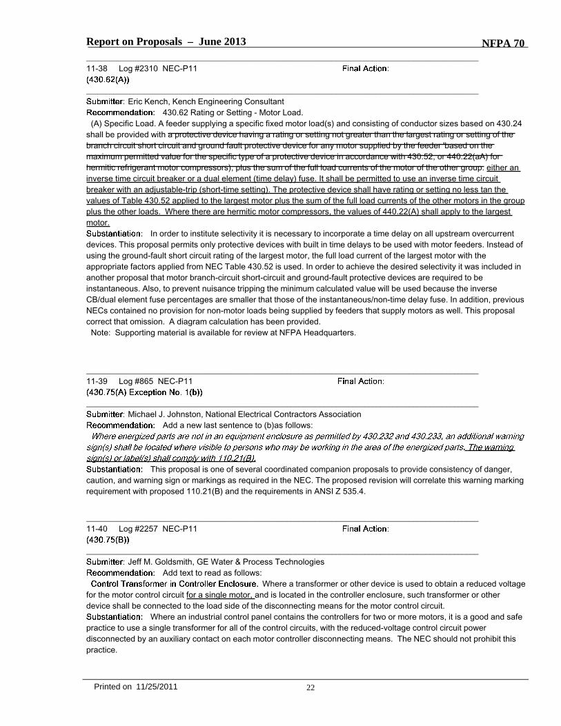
Report on Proposals – June 2013 NFPA 70_______________________________________________________________________________________________11-31 Log #1787 NEC-P11
_______________________________________________________________________________________________Mark Shapiro, Farmington Hills, MI, Michael Anthony, University of Michigan
Insert section and material as shown below as new 430.27. Renumber present Sections 430.27through 430,29.
Where reduced loads result from chiller unitsoperating intermittently or from all chillers not operating at the same time, feeder demand may be calculated from Table430.27
***Insert Table 430.27 Here***
It is noteworthy that the occupancy classes that dominate the subject of electric load calculations ofChapter 2 are residential in nature. Not all, but most. Even Annex D, which contains 13 calculation examples, ispre-occupied with load calculations that apply to residential facility classes. But a large part of the building industry thatuses the NEC is non-residential and needs guidance on what electrical designers need to do when mechanicalengineers submit a load list that involves one or more electric HVAC units supplied from the same service equipment.In most commercial buildings the HVAC equipment makes up the majority of the building's load. This majority trackswell in energy management systems. Without this, 100% demand adds significant capacity that, in most installations,will never be used and increase flash hazard.This proposal is being made to this part of Article 430 rather than to Article 440 because Article 440 is limited to HVACbranch circuits (see 440.1). A companion proposal has also been made for Article 220.
_______________________________________________________________________________________________11-32 Log #2538 NEC-P11
_______________________________________________________________________________________________William Gross, Electric Service of Clinton
Revise text to read as follows:430.27 Capacitors with Motors. Where capacitors are installed in motor circuits they shall comply with 460.8 and 460.9
the following:(1) Be enclosed and mounted externally to the motor.(2) Have a nameplate listing manufacturer ,voltage and kilovar rating when used for power factor correction(3) Comply with sections 460.8 and 460.9
These additions would prevent capacitors from being installed in motor terminal enclosures. Thiswould ensure that the correct type of capacitor equipment will be installed for motor circuits that are being modified forpower factor correction.
16Printed on 11/25/2011

70/L1787/Tb 430.27/A2013/ROP
Table 430.27 Demand Factors for Electric HVAC Units
Number of Units Demand Factor %
1 100 2 80 3 60
4 or more 40

Report on Proposals – June 2013 NFPA 70_______________________________________________________________________________________________11-33 Log #2337 NEC-P11
_______________________________________________________________________________________________Eric Kench, Kench Engineering Consultant
Revise text to read as follows:
Feeders
At the present time there is no rule for the protection of motor feeders at their ampacity. The rules ofPart V of the NEC do not contain any provisions for this type of overcurrent protection except for short-circuit andground-fault protection which is not sufficient. This is due to the oversizing of the SC-GF protection in order toaccomodate the inrush current of motors. This proposal will correct this problem by incorporating a time delay elementinto the feeder overload device.
17Printed on 11/25/2011

Report on Proposals – June 2013 NFPA 70_______________________________________________________________________________________________11-34 Log #1656 NEC-P11
_______________________________________________________________________________________________Mike Weitzel, Central Washington Electrical Education
Add (MCP) Acronym to the description in the Table, and to the following 430.52 text:
***Insert Table 430.52 Here***
The motor branch-circuit short-circuit and ground-fault protective device shall comply with 430.52(8) andeither 430.52(C) or (D), as applicable.
The motor branch-circuit short-circuit and ground-fault protective device shall be capable of carryingthe starting current of the motor.
A protective device that has a rating or setting not exceeding the valuecalculated according to the values given in Table 430.52 shall be used.
Where maximum branch-circuit short-circuit and ground-fault protective device ratings areshown in the manufacturer's overload relay table for use with a motor controller or are otherwise marked on theequipment, they shall not be exceeded even if higher values are allowed as shown above.
An instantaneous trip circuit breaker shall be used only ifadjustable and if part of a listed combination motor controller having coordinated motor overload and short-circuit andground-fault protection in each conductor, and the setting is adjusted to no more than the value specified in Table430.52.
Informational Note: For the purpose of this article, instantaneous trip circuit breakers may include a dampingmeans to accommodate a transient motor inrush current without nuisance tripping of the circuit breaker.
Informational Note: For additional information on the requirements for a motor to be classified "energy efficient," seeNEMA Standards Publication No. MGI-1993, Revision,Motors and Generators, Part 12.59.
18Printed on 11/25/2011
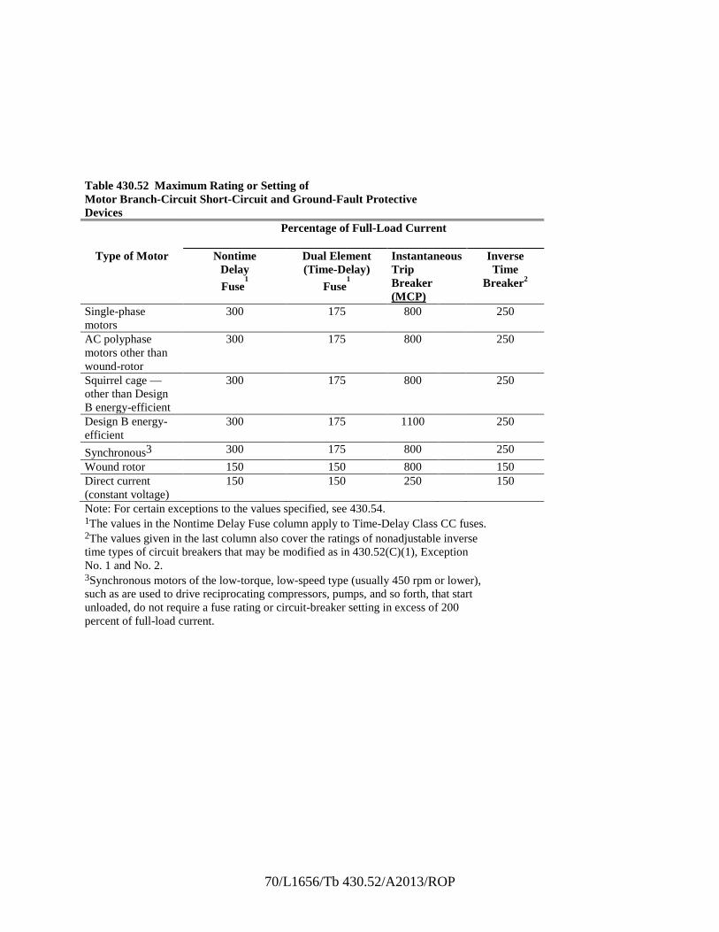
70/L1656/Tb 430.52/A2013/ROP
Table 430.52 Maximum Rating or Setting of Motor Branch-Circuit Short-Circuit and Ground-Fault Protective Devices
Percentage of Full-Load Current
Type of Motor Nontime Delay Fuse
1
Dual Element (Time-Delay)
Fuse1
Instantaneous Trip Breaker (MCP)
Inverse Time
Breaker2
Single-phase motors
300 175 800 250
AC polyphase motors other than wound-rotor
300 175 800 250
Squirrel cage — other than Design B energy-efficient
300 175 800 250
Design B energy-efficient
300 175 1100 250
Synchronous3 300 175 800 250
Wound rotor 150 150 800 150 Direct current (constant voltage)
150 150 250 150
Note: For certain exceptions to the values specified, see 430.54. 1The values in the Nontime Delay Fuse column apply to Time-Delay Class CC fuses. 2The values given in the last column also cover the ratings of nonadjustable inverse time types of circuit breakers that may be modified as in 430.52(C)(1), Exception No. 1 and No. 2. 3Synchronous motors of the low-torque, low-speed type (usually 450 rpm or lower), such as are used to drive reciprocating compressors, pumps, and so forth, that start unloaded, do not require a fuse rating or circuit-breaker setting in excess of 200 percent of full-load current.

Report on Proposals – June 2013 NFPA 70For a multispeed motor, a single short-circuit and ground-fault protective device shall be
permitted for two or more windings of the motor, provided the rating of the protective device does not exceed the aboveapplicable percentage of the nameplate rating of the smallest winding protected.
Suitable fuses shall be permitted in lieu of devices listed in Table 430.52 for powerelectronic devices in a solid-state motor controller system, provided that the marking for replacement fuses is providedadjacent to the fuses.
A listed self protected combination controller shall be permitted in lieu ofthe devices specified in Table 430.52. Adjustable instantaneous-trip settings shall not exceed 1300 percent of full-loadmotor current for other than Design B energy-efficient motors and not more than 1700 percentof full-load motor current for Design B energy-efficient motors.
Informational Note: Proper application of self-protected combination controllers on 3-phase systems. other than solidlygrounded wye, particularly on corner grounded delta systems, considers the self-protected combination controllers'individual pole-interrupting capability.
A motor short-circuit protector shall be permitted in lieu of devices listed in Table430.52 if the motor short-circuit protector is part of a listed combination motor controller having coordinated motoroverload protection and short-circuit and ground-fault protection in each conductor and it will open the circuit at currentsexceeding 1300 percent of motor full-load current for other than Design 8 energy-efficient motors and 1700 percent ofmotor full-load motor current for Design B energy-efficient motors.
Informational Note: A motor short-circuit protector, as used in this section, is a fused device and is not aninstantaneous trip circuit breaker.
Torque motor branch circuits shall be protected at the motor nameplate current rating inaccordance with 240.4(8).
This proposal recommends adding the acronym "MCP" after Instantaneous Trip Circuit Breakereverywhere found in Section 430.52, and at the top of Table 430.52, to coincide with the use of the term in the textof 430.52.
A companion proposal has been submitted to Section 430.2 to add a new definition for Motor Circuit Protector (MCP).Clarity is needed and a clear definition of what a actually Motor Circuit Protector is.If a motor circuit protector is not an instantaneous circuit breaker, then how is it defined?The informational Note presently found in 430.52(C) (7) actually describes a Motor Protector, which is a
fused device, manufactured as I understand, by Ferraz-Shawmut.There has been confusion relating to MCP's and MSCP's.There has been confusion relating to MCP's and MSCP's.For example, a well-known Code-training resource for the 2011 NEC cycle, showed a photo of an instantaneous
breaker installed in an MCC bucket and described it as a "Motor Short-Circuit Protector", which was incorrect. They arenot alone. Many of us have needed clarification.
176,
MCP'sThese are circuit breakers without overload (thermal) protection capability.They are intended to provide only branch-circuit, short-circuit, and ground-fault protection for individual motor branch
circuits.They may not be used to provide main, motor feeder, motor overload, general branch-circuit or group motor protection
...NEC 430.52 requires that they shall only be used as part of a listed combination motor controller.MCP's are short-circuit tested only in combination with a motor controller and overload device.Because of this, they are not labeled with an interrupting rating by themselves.Per NEC 430.109, they may be used as a motor branch-circuit and controller disconnect, or "at the motor " disconnect
19Printed on 11/25/2011

Report on Proposals – June 2013 NFPA 70only when part of a listed combination motor controller.
A companion proposal has been submitted to Section 430.2 to add a new definition for Motor Circuit Protector (MCP),and to Section 430.63, the acronym, MCP.
Note: Supporting material is available for review at NFPA Headquarters.
_______________________________________________________________________________________________11-35 Log #2338 NEC-P11
_______________________________________________________________________________________________Eric Kench, Kench Engineering Consultant
Add text to read as follows:(B) All Motors. The motor branch-circuit short-circuit and ground-fault protective device shall be capable of carrying the
starting current of the motor. The motor branch-circuit short-circuit protective device shall be either an instantaneous tripbreaker or a nontime delay fuse.
In order to achieve selectivity this proposal requires that the motor branch-circuit short-circuit andground-fault protective device should either be an instantaneous circuit breaker or nontime delay fuse. On anotherproposal it was recommended that the motor feeder branch-circuit and ground-fault protective device should have a timedelay feature. Thus selectivity is achieved.
_______________________________________________________________________________________________11-36 Log #111 NEC-P11
_______________________________________________________________________________________________James J. Toth, III, Delta Power Systems Engineering, PC
Revise text to read as follows:(7) As used in this section, a motor short-circuit protector is a fused device and is not
an instantaneous trip circuit breaker. A motor shortcircuit protector shall be permitted in lieu of devices listed in Table430.52 if the motor short-circuit protector is part of a listed combination motor controller having coordinated motoroverload protection and short-circuit and ground-fault protection in each conductor and it will open the circuit at currentsexceeding 1300 percent of motor full-load current for other than Design B energy-efficient motors and 1700 percent ofmotor full-load motor current for Design B energy-efficient motors.
Informational Note. A motor short-circuit protector, as used in this section, is a fused device and is not aninstantaneous trip circuit breaker.
If there are alternate meanings for a motor short-circuit protector, in order to restrict the meaning forthis section, move the “temporary definition” from the informational note (“not enforceable as requirements of this ”)to the code text (similar to 450.6 – “As used in this section, the word …”).
20Printed on 11/25/2011

Report on Proposals – June 2013 NFPA 70_______________________________________________________________________________________________11-37 Log #1764 NEC-P11
_______________________________________________________________________________________________Mike Weitzel, Central Washington Electrical Education
Add text to read as follows:
A feeder supplying a specific fixed motor load(s) and consisting of conductor sizes based on 430.24shall be provided with a protective device having arating or setting not greater than the largest rating or setting of the branch-circuit short-circuit and ground-fault protectivedevice for any motor supplied by the feeder [based onthe maximum permitted value for the specific type of a protective device in accordance with 430.52, or 440.22(A) forhermetic refrigerant motor-compressors], plus the sumof the full-load currents of the other motors of the group.
Where the same rating or setting of the branch-circuit short-circuit and ground-fault protective device is used on two ormore of the branch circuits supplied by the feeder, one of the protective devices shall be considered the largest for theabove calculations.
This proposal recommends adding the acronym "MCP" after Instantaneous Trip Circuit Breaker foundin Section 430.62.
found in Section 430.52, and at the top of Table 430.52, to coincide with the use of the term in thetext of 430.52.
Companion proposals have been submitted to Section 430.2 to add a new definition for Motor Circuit Protector (MCP),and everywhere found in Section 430.52, including at the top of Table 430.52, to coincide with the use of the term in the
text of 430.52, as well as in Section 250.122(0)(2), and Section 430.62.Clarity is needed and a clear definition of what a actually Motor Circuit Protector is.If a motor circuit protector is not an instantaneous circuit breaker, then how is it defined?The informational Note presently found in 430.52(C) (7) actually describes a Motor Short-Circuit Protector, which is a
fused device, manufactured as I understand, by Ferraz-Shawmut.There has been confusion relating to MCP's and MSCP's.For example, a well-known Code-training resource for the 2011 NEC cycle, showed a photo of an instantaneous
breaker installed in an MCC bucket and described it as a "Motor Short-Circuit Protector", which was incorrect. They arenot alone. Many of us have needed clarification.
These are circuit breakers without overload (thermal) protection capability.They are intended to provide only branch-circuit, short-circuit, and ground-fault protection for individual motor branch
circuits.They may not be used to provide main, motor feeder, motor overload, general branch-circuit or group motor protection.NEC 430.52 requires that they shall only be used as part of a listed combination motor controller.MCP's are short-circuit tested only in combination with a motor controller and overload device.Because of this, they are not labeled with an interrupting rating by themselves.Per NEC 430.109, they may be used as a motor branch-circuit and controller disconnect, or "at the motor" disconnect
only when part of a listed combination motor controller.Companion proposals have been submitted to Section 430.2 to add a new definition for Motor Circuit Protector (MCP),
and to the text and Table of Section 430.52, the acronym, MCP.Note: Supporting material is available for review at NFPA Headquarters.
21Printed on 11/25/2011
Report on Proposals – June 2013 NFPA 70_______________________________________________________________________________________________11-38 Log #2310 NEC-P11
_______________________________________________________________________________________________Eric Kench, Kench Engineering Consultant
430.62 Rating or Setting - Motor Load.(A) Specific Load. A feeder supplying a specific fixed motor load(s) and consisting of conductor sizes based on 430.24
shall be provided with a protective device having a rating or setting not greater than the largest rating or setting of thebranch circuit short circuit and ground fault protective device for any motor supplied by the feeder 'based on themaximum permitted value for the specific type of a protective device in accordance with 430.52, or 440.22(aA) forhermitic refrigerant motor compressors), plus the sum of the full load currents of the motor of the other group. either aninverse time circuit breaker or a dual element (time delay) fuse. It shall be permitted to use an inverse time circuitbreaker with an adjustable-trip (short-time setting). The protective device shall have rating or setting no less tan thevalues of Table 430.52 applied to the largest motor plus the sum of the full load currents of the other motors in the groupplus the other loads. Where there are hermitic motor compressors, the values of 440.22(A) shall apply to the largestmotor.
In order to institute selectivity it is necessary to incorporate a time delay on all upstream overcurrentdevices. This proposal permits only protective devices with built in time delays to be used with motor feeders. Instead ofusing the ground-fault short circuit rating of the largest motor, the full load current of the largest motor with theappropriate factors applied from NEC Table 430.52 is used. In order to achieve the desired selectivity it was included inanother proposal that motor branch-circuit short-circuit and ground-fault protective devices are required to beinstantaneous. Also, to prevent nuisance tripping the minimum calculated value will be used because the inverseCB/dual element fuse percentages are smaller that those of the instantaneous/non-time delay fuse. In addition, previousNECs contained no provision for non-motor loads being supplied by feeders that supply motors as well. This proposalcorrect that omission. A diagram calculation has been provided.
Note: Supporting material is available for review at NFPA Headquarters.
_______________________________________________________________________________________________11-39 Log #865 NEC-P11
_______________________________________________________________________________________________Michael J. Johnston, National Electrical Contractors Association
Add a new last sentence to (b)as follows:
This proposal is one of several coordinated companion proposals to provide consistency of danger,caution, and warning sign or markings as required in the NEC. The proposed revision will correlate this warning markingrequirement with proposed 110.21(B) and the requirements in ANSI Z 535.4.
_______________________________________________________________________________________________11-40 Log #2257 NEC-P11
_______________________________________________________________________________________________Jeff M. Goldsmith, GE Water & Process Technologies
Add text to read as follows:Where a transformer or other device is used to obtain a reduced voltage
for the motor control circuit for a single motor, and is located in the controller enclosure, such transformer or otherdevice shall be connected to the load side of the disconnecting means for the motor control circuit.
Where an industrial control panel contains the controllers for two or more motors, it is a good and safepractice to use a single transformer for all of the control circuits, with the reduced-voltage control circuit powerdisconnected by an auxiliary contact on each motor controller disconnecting means. The NEC should not prohibit thispractice.
22Printed on 11/25/2011
Report on Proposals – June 2013 NFPA 70_______________________________________________________________________________________________11-41 Log #51 NEC-P11
_______________________________________________________________________________________________
Jeff M. Goldsmith, General Electric CompanyChange the proposed modification of a definition in 430.2 to the addition of a new subsection (C) in
430.81, to read:A listed VAM controlled by an industrial control panel shall be
permitted to be classified as a control circuit load, wired as an Article 725 remote-control circuit.Informational Note: Listed valve actuators comply with the UL 429 Standard for Electrically Operated Valves.
ln response to the panel statement on my proposal:UL 429 section 25.3 includes "The temperature rise attained by the motor of a motor-operated valve. lf stalling the
motor is not part of the normal operation, ... the motor, when stalled or otherwise operated with a blocked valve system,shall not show any manifestation of a risk of fìre," UL 429 does apply to motor-operated valves, and to motor-operatedvalve actuators that are one of the two principal components.
UL 50BA section 46.1.1 says: "A control circuit load shall comply with . . . b) An electrically-operated valve shall complywith . . . UL 429". The opposite of a UL 508A control circuit is a power circuit, which UL 508A defines as “Conductorsand components of branch and feeder circuits." Therefore, UL 508A says that a motor-operated valve control circuit isnot necessarily a branch circuit or a motor branch circuit.
The Control Circuit definition in Article 409 includes "carries the electric signals directing the performance of thecontroller". A motor-operated valve actuator directs the fluid switching performance of a valve. Adding a word to theRemote-Control Circuit definition "Any electrical circuit that controls any other [fluid] circuit through a relay or anequivalent device" shows that valve actuator circuits are essentially 725.41(B) Class 1 Remote-Control and SignalingCircuits.
UL 508A defines limits for control circuit loads, and section 51 requires load rating markings on a listed panel. So"controlled by an industrial control panel" works in 430.81 that "is intended to require suitable controllers for all motors".
23Printed on 11/25/2011

Report on Proposals – June 2013 NFPA 70_______________________________________________________________________________________________11-42 Log #3323 NEC-P11
_______________________________________________________________________________________________Steven Goble, Olathe, KS
Insert the following new requirement.
Throughout its history, the NEC® has mandated the practical safeguarding of persons and propertyfrom hazards arising from the use of electricity. However, one of the hazards that is often overlooked is damage toproperty, such as fire, or the destruction of appliances and electronic equipment, due to surges caused by (1) thestarting and stopping of power electronic equipment, (2) direct or indirect lightning strikes, and (3) imposition of a highervoltage on a lower voltage system. While NFPA 70 haslong recognized the practical application of surge protective devices as evidenced by several NEC® Articles, includingbut not limited to, 285, 694 and 708, the vast majority of equipment is not required to be protected from damage bysurges. This lack of required protection results in, as the State Farm Insurance Company notes on their web site, " ...power surges are responsible for hundreds of millions of dollars of property damage every year ... Over time, surges canalso cause cumulative damage to your property, incrementally decreasing the lifespan of televisions, computers, stereoequipment, and anything else plugged into the wall."
This proposal is intended to expand protection against damaging surges through the use of listed surge protectivedevices. While progress has been made in this area, it is evident that expanded use of listed surge protective deviceswill be a step function improvement to the practical safeguarding of persons and property.Some very recent specific examples of events that call attention to this need include the documented destruction of ahouse due to electrical surge as a result of a transformer fire. This occurred in Kings County California in October of2011.
In the UK in 2010, 71 incidents were caused by electrical power surges according to the fire inspector. In fact, thecause of the surge was related to the theft of a copper component in a substation. Of the 71 incidents, 48 resulted indamage to electrical equipment, including 36 panelboards, a number of televisions, washing machines and otherelectrical appliances.
In Dallas, Texas, a utility electric crew repairing a transformer in front of a residence caused a significant surge. Thetransformer was seen to be arcing with the subsequent destruction of equipment in nearby homes. This included CentralHeat and Air units, refrigerators, washers, dryers .... and the like.
Another recent event in Carthage, MO, occurred in October of 2011. Lightning hit the Jasper County Jail and theresultant surge knocked out the security system as well as fire alarms, locks and other key systems. The same eventalso resulted in a small fire at a Carthage home. Only because of an alert homeowner and quick response by the localfire department was extensive damage and possible loss of life prevented.
Studies by recognized authorities including NEMA, IEEE, and UL, all substantiate the fact that surges can and docause significant damage. Nationwide Insurance recognizes the need for effective surge protection as well and haspublished recommendations that include point-of-use surge protectors and installation of main service panelsuppressors.
Unprotected surges do cause catastrophic damage to industrial, commercial and residential electronic equipment andresidential appliances, sometimes resulting in fire and loss of life. Surge protective devices are readily available toprotect against these common surges, but have simply not been required in most applications. This Code Making Panelhas the opportunity to take a significant step toward better protection of persons and property by accepting thisproposal.
24Printed on 11/25/2011

Report on Proposals – June 2013 NFPA 70_______________________________________________________________________________________________11-43 Log #361 NEC-P11
_______________________________________________________________________________________________Edward G. Kroth, Verona, WI
Delete Table 430.97 and change 430.97(D) as follows:Spacings between motor control center bus terminals and other bare metal parts shall not be
less than specified in Table 430.97 408.56.This proposal is an effort to eliminate unnecessary duplication of another table. The only difference
between these two tables is the asterisk in the third column of Table 408.56. This note refers us back to the spacingrequirements in 312.11(A)(1), (2) and (3). Electrons do not know whether they are in a cabinet, cut out box or metersocket versus in a motor control center or industrial control panel. So if the note is important for safety in one it shouldbe applicable to all. A similar proposal is being submitted for 409.106.
_______________________________________________________________________________________________11-44 Log #2258 NEC-P11
_______________________________________________________________________________________________Jeff M. Goldsmith, GE Water & Process Technologies
Add text to read as follows:An individual disconnecting means shall be provided for each controller. At its open position, this
disconnecting means and shall disconnect the controller from line power, and shall cause the controller to break theconnection between the motor and the disconnecting means. The disconnecting means shall be located in sight fromthe controller location.
The existing “disconnect the controller” is ambiguous. This proposal defines two specific performancerequirements for safety.
The proposed “disconnect the controller from line power” complements the rules for control circuit disconnection in430.75.
There is an issue between 430.110(A) and the allowing of separate devices in 430.75(A). If a separate control circuitdisconnect allows the motor starter to be on when the controller disconnecting means is open, the motor can start whenthe controller disconnecting means is switched from open to closed. Many disconnect switches can fail when acting asfull-voltage motor starters. The “cause the controller to break the connection” requirement prevents this situation.
25Printed on 11/25/2011

Report on Proposals – June 2013 NFPA 70_______________________________________________________________________________________________11-45 Log #291 NEC-P11
_______________________________________________________________________________________________Stanley J. Folz, Morse Electric Company
Revise text to read as follows:
An individual disconnecting means shall be provided for each controller and shall disconnect thecontroller. The disconnecting means shall be located in sight from the controller location.
Exception No. 1: For motor circuits over 600 volts, nominal, a controller disconnecting means lockable in accordancewith 110.25 capable of being locked in the open position shall be permitted to be out of sight of the controller, providedthe controller is marked with a warning label giving the location of the disconnecting means.
This proposal has been developed by the Usability Task Group assigned by the Technical CorrelatingCommittee. The committee members were Stanley Folz, James Dollard, William Fiske, David Hittinger, Andy Juhasz,Amos Lowrance, Susan Newman-Scearce, Marc Bernsen and Vincent Zinnante. Requirements for a disconnectingmeans to be lockable in the open position exist in numerous locations in the NEC. A new section has been proposed inArticle 110 to consolidate the requirements for a disconnecting means required to be “capable of being locked in theopen position” in a single section for clarity. It is understood that this requirement includes more than disconnecting andlocking electrical power sources.
This proposal is intended to facilitate a lockout/tagout scenario. It is equally important to ensure that the means forplacing the lock remain in place. The concept suggested by this proposal is necessary to provide correlation throughoutthe NEC with respect to the capability of placing a lock on a disconnecting means to secure it in the open position.
_______________________________________________________________________________________________11-46 Log #866 NEC-P11
_______________________________________________________________________________________________Michael J. Johnston, National Electrical Contractors Association
Add a new last sentence to Exc. No. 1 and Exc. No. 3 (a) as follows:
This proposal is one of several coordinated companion proposals to provide consistency of danger,caution, and warning sign or markings as required in the NEC. The proposed revision will correlate this warning markingrequirement with proposed 110.21(B) and the requirements in ANSI Z 535.4.
_______________________________________________________________________________________________11-47 Log #477 NEC-P11
_______________________________________________________________________________________________Edward G. Kroth, Verona, WI
Revise text to read as follows:
The remainder of this exception should remain the same.This is a companion proposal to one submitted to Code-Making Panel 1 and should be accepted only
if said proposal or some equivalent proposal is accepted by Code-Making Panel 1. Said proposal is to put the criteria fora lockable disconnecting means in Article 110 and, thus, be able to eliminate similar repetitions in at least 19 differentsections of the NEC. It would also help to standardize the usage of the term "capable of being locked" which has atleast four variations in the 2011 NEC.
26Printed on 11/25/2011

Report on Proposals – June 2013 NFPA 70_______________________________________________________________________________________________11-48 Log #292 NEC-P11
_______________________________________________________________________________________________Stanley J. Folz, Morse Electric Company
Revise text to read as follows:Exception No. 3: The disconnecting means shall not be required to be in sight from valve actuator motor (VAM)
assemblies containing the controller where such a location introduces additional or increased hazards to persons orproperty and conditions (a) and (b) are met.
(a) The valve actuator motor assembly is marked with a warning label giving the location of the disconnecting means.(b) The provision for locking or adding a lock to the disconnecting means shall be lockable in accordance with 110.25.
shall be installed on or at the switch or circuit breaker used as the disconnecting means and shall remain in place with orwithout the lock installed.
This proposal has been developed by the Usability Task Group assigned by the Technical CorrelatingCommittee. The committee members were Stanley Folz, James Dollard, William Fiske, David Hittinger, Andy Juhasz,Amos Lowrance, Susan Newman-Scearce, Marc Bernsen and Vincent Zinnante. Requirements for a disconnectingmeans to be lockable in the open position exist in numerous locations in the NEC. A new section has been proposed inArticle 110 to consolidate the requirements for a disconnecting means required to be “capable of being locked in theopen position” in a single section for clarity. It is understood that this requirement includes more than disconnecting andlocking electrical power sources.
This proposal is intended to facilitate a lockout/tagout scenario. It is equally important to ensure that the means forplacing the lock remain in place. The concept suggested by this proposal is necessary to provide correlation throughoutthe NEC with respect to the capability of placing a lock on a disconnecting means to secure it in the open position.
_______________________________________________________________________________________________11-49 Log #293 NEC-P11
_______________________________________________________________________________________________Stanley J. Folz, Morse Electric Company
Revise text to read as follows:Exception to (1) and (2): The disconnecting means for the motor shall not be required under either condition (a) or
condition (b), provided the controller disconnecting means required in accordance with 430.102(A) is lockable inaccordance with 110.25. individually capable of being locked in the open position. The provision for locking or adding alock to the controller disconnecting means shall be installed on or at the switch or circuit breaker used as thedisconnecting means and shall remain in place with or without the lock installed.
This proposal has been developed by the Usability Task Group assigned by the Technical CorrelatingCommittee. The committee members were Stanley Folz, James Dollard, William Fiske, David Hittinger, Andy Juhasz,Amos Lowrance, Susan Newman-Scearce, Marc Bernsen and Vincent Zinnante. Requirements for a disconnectingmeans to be lockable in the open position exist in numerous locations in the NEC. A new section has been proposed inArticle 110 to consolidate the requirements for a disconnecting means required to be “capable of being locked in theopen position” in a single section for clarity. It is understood that this requirement includes more than disconnecting andlocking electrical power sources.
This proposal is intended to facilitate a lockout/tagout scenario. It is equally important to ensure that the means forplacing the lock remain in place. The concept suggested by this proposal is necessary to provide correlation throughoutthe NEC with respect to the capability of placing a lock on a disconnecting means to secure it in the open position.
27Printed on 11/25/2011

Report on Proposals – June 2013 NFPA 70_______________________________________________________________________________________________11-50 Log #478 NEC-P11
_______________________________________________________________________________________________Edward G. Kroth, Verona, WI
Delete text as follows:
The restof the exception is to remain the same.
This is a companion proposal to one submitted to Code-Making Panel 1 and should be accepted onlyif said proposal or some equivalent proposal is accepted by Code-Making Panel 1. Said proposal is to put the criteria fora lockable disconnecting means in Article 110 and, thus, be able to eliminate similar repetitions in at least 19 differentsections of the NEC. It would also help to standardize the usage of the term "capable of being locked" which has atleast four variations in the 2011 NEC.
_______________________________________________________________________________________________11-51 Log #1873 NEC-P11
_______________________________________________________________________________________________Michael Dempsey, Municipal Code Inspections
Revise text to read as follows:Some examples of impracticable, increased or additional hazards.
To make the informational note consistent with wording in 430.102(B)(2) Exception (a), the wording aswritten only seems to apply to motors that could increase hazards, or are located in hazardous or industrial locations.
_______________________________________________________________________________________________11-52 Log #692 NEC-P11
_______________________________________________________________________________________________Roger Zieg, Zieg Electric
Delete text as follows:(b) In industrial installations, with written procedures, where conditions of maintenance and supervision ensure that
only qualified persons service the equipment.The purpose of the is the practical safeguarding of persons and property from hazards arising
from the use of electricity. Qualified person is defined in the , but the meaning is certainly open to interpretation.Some states and/or local jurisdictions do not require the licensing of industrial electricians and leave it to the individualindustrial establishment to define the meaning of the qualified person. It is my belief that this exception should bedeleted because it does not provide practical safeguarding for the qualified person. Why should the qualified person beoffered less protection, especially in this day of electrical safe work practices?
_______________________________________________________________________________________________11-53 Log #867 NEC-P11
_______________________________________________________________________________________________Michael J. Johnston, National Electrical Contractors Association
Add a new last sentence as follows:"…Where multiple disconnecting means are provided, a permanent warning sign shall be provided on or adjacent to
each disconnecting means. The warning sign(s) or label(s) shall comply with 110.21(B).This proposal is one of several coordinated companion proposals to provide consistency of danger,
caution, and warning sign or markings as required in the NEC. The proposed revision will correlate this warning markingrequirement with proposed 110.21(B) and the requirements in ANSI Z 535.4.
28Printed on 11/25/2011
Report on Proposals – June 2013 NFPA 70_______________________________________________________________________________________________11-54 Log #294 NEC-P11
_______________________________________________________________________________________________Stanley J. Folz, Morse Electric Company
Revise text to read as follows:Exception No. 1: Where a motor receives electric energy from more than one source, the disconnecting means for the
main power supply to the motor shall not be required to be immediately adjacent to the motor, provided the controllerdisconnecting means is lockable in accordance with 110.25. capable of being locked in the open position.
This proposal has been developed by the Usability Task Group assigned by the Technical CorrelatingCommittee. The committee members were Stanley Folz, James Dollard, William Fiske, David Hittinger, Andy Juhasz,Amos Lowrance, Susan Newman-Scearce, Marc Bernsen and Vincent Zinnante. Requirements for a disconnectingmeans to be lockable in the open position exist in numerous locations in the NEC. A new section has been proposed inArticle 110 to consolidate the requirements for a disconnecting means required to be “capable of being locked in theopen position” in a single section for clarity. It is understood that this requirement includes more than disconnecting andlocking electrical power sources.
This proposal is intended to facilitate a lockout/tagout scenario. It is equally important to ensure that the means forplacing the lock remain in place. The concept suggested by this proposal is necessary to provide correlation throughoutthe NEC with respect to the capability of placing a lock on a disconnecting means to secure it in the open position.
29Printed on 11/25/2011

Report on Proposals – June 2013 NFPA 70_______________________________________________________________________________________________11-55 Log #3324 NEC-P11
_______________________________________________________________________________________________Steven Goble, Olathe, KS
Insert the following new requirement.430.121 Surge Protection. A listed SPD shall be installed in or on all adjustable-speed drive systems.
Throughout its history, the NEC® has mandated the practical safeguarding of persons and propertyfrom hazards arising from the use of electricity. However, one of the hazards that is often overlooked is damage toproperty, such as fire, or the destruction of appliances and electronic equipment, due to surges caused by (1) thestarting and stopping of power electronic equipment, (2) direct or indirect lightning strikes, and (3) imposition of a highervoltage on a lower voltage system. While NFPA 70 has long recognized the practical application of surge protectivedevices as evidenced by several NEC® Articles, including but not limited to, 285, 694 and 708, the vast majority ofequipment is not required to be protected from damage by surges. This lack of required protection results in, as theState Farm Insurance Company notes on their web site, " ... power surges are responsible for hundreds of millions ofdollars of property damage every year ... Over time, surges can also cause cumulative damage to your property,incrementally decreasing the lifespan of televisions, computers, stereo equipment, and anything else plugged into thewall."
This proposal is intended to expand protection against damaging surges through the use of listed surge protectivedevices. While progress has been made in this area, it is evident that expanded use of listed surge protective deviceswill be a step function improvement to the practical safeguarding of persons and property.Some very recent specific examples of events that call attention to this need include the documented destruction of ahouse due to electrical surge as a result of a transformer fire. This occurred in Kings County California in October of2011.In the UK in 2010, 71 incidents were caused by electrical power surges according to the fire inspector. In fact, the causeof the surge was related to the theft of a copper component in a substation. Of the 71 incidents, 48 resulted in damageto electrical equipment, including 36 panelboards, a number of televisions, washing machines and other electricalappliances.
In Dallas, Texas, a utility electric crew repairing a transformer in front of a residence caused a significant surge. Thetransformer was seen to be arcing with the subsequent destruction of equipment in nearby homes. This included CentralHeat and Air units, refrigerators, washers, dryers .... and the like.Another recent event in Carthage, MO, occurred in October of 2011. Lightning hit the Jasper County Jail and theresultant surge knocked out the security system as well as fire alarms, locks and other key systems. The same eventalso resulted in a small fire at a Carthage home. Only because of an alert homeowner and quick response by the localfire department was extensive damage and possible loss of life prevented.
Studies by recognized authorities including NEMA, IEEE, and UL, all substantiate the fact that surges can and docause significant damage. Nationwide Insurance recognizes the need for effective surge protection as well and haspublished recommendations that include point-of-use surge protectors and installation of main service panelsuppressors.
Unprotected surges do cause catastrophic damage to industrial, commercial and residential electronic equipment andresidential appliances, sometimes resulting in fire and loss of life. Surge protective devices are readily available toprotect against these common surges, but have simply not been required in most applications. This Code Making Panelhas the opportunity to take a significant step toward better protection of persons and property by accepting thisproposal.
30Printed on 11/25/2011

Report on Proposals – June 2013 NFPA 70_______________________________________________________________________________________________11-56 Log #104 NEC-P11
_______________________________________________________________________________________________
Code-Making Panel 11,Text Recommendation: Revise text to read as follows:
The branch circuit short-circuit and ground-fault protection for a circuit supplyingpower conversion equipment shall be of the type and size specified by the manufacturer’s instructions provided with thepower conversion equipment. When the instructions do not specify the type and size, a branch-circuit fuse orinverse-time circuit breaker shall be used and shall be sized based upon the input current rating of the power conversionequipment multiplied by the percentage from Table 430.52.
Additional branch circuit short-circuit and ground-fault protection is not required for powerconversion equipment where provided with integral branch circuit rated protection such as: an inverse-time circuitbreaker, branch-circuit fuses or semiconductor fuses, as provided in section 430.52(C)(5), in all ungrounded inputconductors.
Unless specified in the manufacturer’s instructions supplied with the power conversion equipment,”common dc bus” power conversion equipment is not required to have individual branch circuit protective devicesinstalled in the dc input conductors.
Where a branch circuit short-circuit and ground-fault protective device providesprotection for both the adjustable speed drive system and a bypass circuit, the specific branch circuit protective deviceand its ratings or settings must not exceed those marked on the adjustable speed drive controller. Where the bypasscircuit requires a different branch circuit short-circuit and ground-fault protective device, ratings or settings other thanthose marked on the adjustable speed drive controller, then separate branch circuit short-circuit and ground-faultprotection shall be provided for both the adjustable speed drive controller and bypass circuit.
Substantiation: The panel has incorporated the intent of the submitters of both 11-108 and 11-110.Text Recommendation: Revise 430.123 to read as follows:
430.123 Branch Circuit Short-Circuit and Ground Fault Protection.(A) Drive Protection and Markings. The branch circuit short-circuit and ground-fault protection for a circuit supplying an
adjustable-speed drive system shall be of a type and ampere rating or setting not exceeding that specified by themanufacturer’s instructions provided with the adjustable-speed drive system. If the instructions do not specify a type andampere rating or setting, a branch-circuit fuse or inverse-time circuit breaker shall be used and shall be sized inaccordance with 430.52 based upon the input current rating of the adjustable-speed drive system. The rating or settingof the overcurrent protective device shall not exceed that allowed by 430.52.
Exception No. 1: Additional branch circuit short-circuit and ground-fault protection for an adjustable-speed drive systemis not required if the adjustable-speed drive system is provided with integral branch circuit rated protection such as aninverse-time circuit breaker, branch-circuit fuses, or semiconductor fuses [430.52(C)(5)].
Exception No. 2: Unless specified in the manufacturer’s instructions supplied with the adjustable-speed drive system,”common dc bus” adjustable-speed drive system designed as part of a single integrated drive system shall not berequired to have individual branch circuit protective devices installed in the dc input conductors.
(B) Drive and Bypass Protection. If a branch circuit short-circuit and ground-fault protective device provides protectionfor both the adjustable-speed drive system and a bypass circuit, the specific branch circuit protective device and itsratings or settings shall not exceed those specified by the manufacturer’s instructions provided with theadjustable-speed drive system. If the bypass circuit requires different branch circuit short-circuit and ground-faultprotection, separate branch circuit short-circuit and ground-fault protection shall be provided for both theadjustable-speed drive system and the bypass circuit.
Substantiation: The panel has modified the language accepted by Proposal 11-107a to incorporate the changesaccepted in the actions on Comments 11-44, 45, 46 and 47. The panel has included additional revisions for clarity.
This proposal 11-107a and comment 11-43a were returned to Committee at the A2010 AssociationTechnical Meeting and/or subsequent Standards Council Meeting. In accordance with 4.7.1(d) and 4.7.2(c) of theRegulations Governing Committee Projects, it is now being processed as a Proposal for this revision cycle.
31Printed on 11/25/2011

Report on Proposals – June 2013 NFPA 70_______________________________________________________________________________________________11-57 Log #2322 NEC-P11
_______________________________________________________________________________________________Eric Kench, Kench Engineering Consultant
Revise text to read as follows:(A) General. Adjustable speed drives shall protect against motor overtemperature conditions where the motor is not
rated to operate at operates at less than the nameplate rated current over the speed required by the application.This NEC section was revised for the 2008 NEC. Although the substantiation submitted with the
previous proposal clearly indicates a problem with overheating caused by insufficient fan ventilation when the ASDoperates at lower speeds, the wording is still incorrect. The proposal I am submitting will revise the text to reflect theproper wording of this NEC section. An ADS operating at lower speeds will draw less current but can still overheat if thefan is operating at less RPMS.
_______________________________________________________________________________________________11-58 Log #184 NEC-P11
_______________________________________________________________________________________________Garry Street, Glen Haven, CO
Revise text to read as follows:Revise 430.126(A)(2) in this manner:(2) Adjustable speed drive system with load and speed-sensitive overload overtemperature protection and thermal
memory retention upon shutdown or power loss430.126 is for "Motor Overtemperature Protection".
-430.126(A) is to "protect against motor overtemperature".-430.126(A)(3) describes "overtemperature protection".In contrast, 430.126(A)(2) describes, load and speed-sensitive "overload" protection.In Definitions 100, "overload" is described...in excess of normal, full-load rating, or...in excess of rated ampacity.Finally, 430.126(A)(4) FPN explains, overheating of motors can occur...even at "current levels less than a motor's rated
full-load current..." (overtemperature not overload).The removal of "overload" replaced with "overtemperature" in 430.126(A)(2) would make this wording match the code
section titled overtemperature and the overload definition intent.
32Printed on 11/25/2011

Report on Proposals – June 2013 NFPA 70_______________________________________________________________________________________________11-59 Log #3091 NEC-P11
_______________________________________________________________________________________________Frederic P. Hartwell, Hartwell Electrical Services, Inc.
Revise as follows:The disconnecting means shall be permitted to be in the incoming line to the
conversion equipment and shall have a rating not less than 115 percent of the rated input current of the conversion unit.Where the drive functions as the controller for the motor, the location of the disconnect shall comply with 430.102(A).
Exception: The disconnecting means for the drive shall not be required to be within sight under either condition (a) or(b) provided a remote disconnecting means is provided that is individually capable of being locked in the open position.The provision for locking or adding a lock to the disconnecting means shall be installed on or at the switch or circuitbreaker used for this purpose and shall remain in place with or without the lock installed.
(a) Where positioning the disconnecting means for the drive within sight is impracticable or introduces additional orincreased hazards to persons or property
(b) In industrial installations, with written safety procedures, where conditions of maintenance and supervision ensurethat only qualified persons service the drive.
Frequently adjustable speed drives meet the definition of a controller in 430.2; they routinely start andstop the motor by making and breaking the power circuit, as well as changing its frequency for speed regulationpurposes. The question then arises as to whether 430.102(A) applies to such a drive, requiring an in-sight disconnect.Many smaller drives are located in areas where a local disconnect might not be desired and would qualify for omissionunder 430.102(B) Exception. However, that exception only applies to the local motor disconnect and not to a controllerdisconnect. The vagueness of the disconnect rule in this part of the article has been used to justify the omission of localdrive disconnects, with the understanding that a locking disconnect could be arranged at some point upstream, just notin sight of the remote drive. This proposal extends the concepts in 430.102(B) Exception to this application as aworkable compromise that recognizes the increasing uses of variable frequency drives at remote motor locations.
_______________________________________________________________________________________________11-60 Log #2642 NEC-P11
_______________________________________________________________________________________________John R. Kovacik, Underwriters Laboratories Inc.
Add an exception to 430.128 as follows;
The disconnecting means shall be permitted to be in the incoming line to theconversion equipment and shall have a rating not less than 115 percent of the rated input current of the conversion unit.
Exception: Where the output rating of a conversion unit is oversized for the motor(s) to be controlled, the input currentrating of the conversion unit shall be permitted to be de-rated for determining the rating of the disconnecting means. Theallowable de-rating shall be determined by multiplying the input current rating of the power conversion unit by the ratio ofthe full-load current rating of the motor(s) to the conversion unit output rating.
Power conversion equipment is often oversized for the motor(s) to be controlled. Because thedisconnecting means is sized based on the input current rating on the conversion equipment and not the motor full loadcurrent, this can result in the required disconnecting means being unnecessarily large for the motor(s) to be controlled.The proposed exception will provide some needed relief for those applications.
33Printed on 11/25/2011

Report on Proposals – June 2013 NFPA 70_______________________________________________________________________________________________11-61 Log #1032 NEC-P11
_______________________________________________________________________________________________James T. Dollard, Jr., IBEW Local Union 98
Replace 600V with 1000V.This proposal is the work of the “High Voltage Task Group” appointed by the Technical Correlating
Committee. The task group consisted of the following members: Alan Peterson, Paul Barnhart, Lanny Floyd, AlanManche, Donny Cook, Vince Saporita, Roger McDaniel, Stan Folz, Eddie Guidry, Tom Adams, Jim Rogers and JimDollard.
The Task Group identified the demand for increasing voltage levels used in wind generation and photovoltaic systemsas an area for consideration to enhance existing NEC requirements to address these new common voltage levels. Thetask group recognized that general requirements in Chapters 1 through 4 need to be modified before identifying andgenerating proposals to articles such as 690 specific for PV systems. These systems have moved above 600V and arereaching 1000V due to standard configurations and increases in efficiency and performance. The committee reviewedChapters 1 through 8 and identified areas where the task group agreed that the increase in voltage was of minimal or noimpact to the system installation. Additionally, there were requirements that would have had a serious impact and thetask group chose not to submit a proposal for changing the voltage. See table (supporting material) that summarizes allsections considered by the TG.
Note: Supporting material is available for review at NFPA Headquarters.
_______________________________________________________________________________________________11-62 Log #2793 NEC-P11
_______________________________________________________________________________________________James F. Williams, Fairmont, WV
Revise text to read as follows:Flexible metal conduit (FMC) or liquidtight flexible metal conduit not
exceeding 1.8 m (6 ft) in length shall be permitted to be employed for raceway connection to a motor terminal enclosure."Flexible Metal Conduit" is also referred to as “FMC”
Suggest that “(FMC)” be added to all references. This will make finding all references to "Flexible Metal Conduit"easier and more reliable.
_______________________________________________________________________________________________11-63 Log #2826 NEC-P11
_______________________________________________________________________________________________James F. Williams, Fairmont, WV
Revise text to read as follows:Flexible metal conduit or liquidtight flexible metal conduit (LFMC) not
exceeding 1.8 m (6 ft) in length shall be permitted to be employed for raceway connection to a motor terminal enclosure.
The junction box required by 430.245(A) shall be permitted to beseparated from the motor by not more than 1.8 m (6 ft), provided the leads to the motor are stranded conductors withinType AC cable, interlocked metal tape Type MC cable where listed and identified in accordance with 250.118(10)(a), orarmored cord or are stranded leads enclosed in liquidtight flexible metal conduit (LFMC), flexible metal conduit,intermediate metal conduit, rigid metal conduit, or electrical metallic tubing not smaller than metric designator 12 (tradesize 3/8), the armor or raceway being connected both to the motor and to the box.Liquidtight flexible nonmetallic conduit (LFMC) and rigid nonmetallic conduit shall be permitted to enclose the leads tothe motor, provided the leads are stranded and the required equipment grounding conductor is connected to both themotor and to the box.
"Liquidtight Flexible Metal Conduit" is also referred to as “LFMC”Suggest that “(LFNC)” be added to all references. This will make finding all references to " Liquidtight Flexible Metal
Conduit " easier and more reliable.
34Printed on 11/25/2011

Report on Proposals – June 2013 NFPA 70_______________________________________________________________________________________________11-64 Log #295 NEC-P11
_______________________________________________________________________________________________Stanley J. Folz, Morse Electric Company
Revise text to read as follows:The controller disconnecting means shall be lockable in accordance with 110.25
capable of being locked in the open position. The provision for locking or adding a lock to the disconnecting means shallbe installed on or at the switch or circuit breaker used as the disconnecting means and shall remain in place with orwithout the lock installed.
This proposal has been developed by the Usability Task Group assigned by the Technical CorrelatingCommittee. The committee members were Stanley Folz, James Dollard, William Fiske, David Hittinger, Andy Juhasz,Amos Lowrance, Susan Newman-Scearce, Marc Bernsen and Vincent Zinnante. Requirements for a disconnectingmeans to be lockable in the open position exist in numerous locations in the NEC. A new section has been proposed inArticle 110 to consolidate the requirements for a disconnecting means required to be “capable of being locked in theopen position” in a single section for clarity. It is understood that this requirement includes more than disconnecting andlocking electrical power sources.
This proposal is intended to facilitate a lockout/tagout scenario. It is equally important to ensure that the means forplacing the lock remain in place. The concept suggested by this proposal is necessary to provide correlation throughoutthe NEC with respect to the capability of placing a lock on a disconnecting means to secure it in the open position.
_______________________________________________________________________________________________11-65 Log #3356 NEC-P11
_______________________________________________________________________________________________James C. Missildine, Jr., Southern Company Services, Inc.
Add new text to read as follows:The motor terminal housing for motors over 600 Volts, Nominal shall provide
adequate space to maintain proper spacing between phases, allow space for proper termination of shielded andmulticonductor cables where used and room to train cable without violating the minimum bending radius of the cablesand terminations.
More room is required in the motor terminal housing in order to terminate shielded cables now wherenon-shielded cables were previously used. The smallest size Type I terminal housing in NEMA MG 1-2009 is for motorsbetween 250 and 1000 HP and only requires 12.6 inches from the field conduit entrance to the centerline of the motorleads. This space must be adequate for: (1) The motor lead O.D., (2) The motor lead MBR as it turns down, (3) Lug onMotor Lead and Lug on Field Cable bolted together, (4) Shielded cable termination stress control, (5) room to train fieldcables without violating 12 × O.D. MBR , (6) Space to allow breakout boot if 3/c cable is used for the feeder. Note: Atleast one manufacturer of terminations requires 0.6 inches spacing between terminations on different phases, so thecable fan-out must provide room for the 0.6 inch spread.
35Printed on 11/25/2011

Report on Proposals – June 2013 NFPA 70_______________________________________________________________________________________________11-66 Log #841 NEC-P11
_______________________________________________________________________________________________Roger Zieg, Zieg Electric
Revise text to read as follows:Exposed live parts of motors and controllers operating at 50 volts or more between
terminals shall be guarded againstaccidental contact by enclosure or by location as follows:
(1) By installation in a room or enclosure that is accessible only to qualified persons(2) By installation on a suitable balcony, gallery, or platform, elevated and arranged so as to exclude unqualified
persons(3) By elevation 2.5 m (8 ft) or more above the floor
The words "...by enclosure or by location" do not add to the requirement. The wording is redundant inthe requirements set forth in (1), (2), and (3). Location as defined in the Code refers to 3 locations: dry, damp, and wet.Live parts installed in an enclosure are located within the enclosure and therefore the enclosure is a location. This is aproposed change which is accompanied by a proposed change for 430.233, also.
_______________________________________________________________________________________________11-67 Log #842 NEC-P11
_______________________________________________________________________________________________Roger Zieg, Zieg Electric
Revise text to read as follows:Where live parts of motors or controllers operating at over 150 volts to ground are
guarded against accidental contact only by location as specified in 430.232, and where adjustment or other attendancemay be necessary during the operation of the apparatus, suitable insulating mats or platforms shall be provided so thatthe attendant cannot readily touch live parts unless standing on the mats or platforms.
The purpose of the Code is the practical safeguarding of persons and property from the hazardsarising from the use of electricity. Providing mats and/or platforms for the persons either working on the equipment ormaking adjustments to the equipment will add to the safeguarding of these persons. The requirement is there forproviding this protection. The purpose of this proposal is to provide this protection for all energized equipment. Locationas defined in the Code is defined as three places: damp, dry, and wet. Placing energized equipment in an enclosure isalso a location for this equipment. This proposal is a companion proposal to 430.232 which proposes eliminatingreference to location and enclosure.
_______________________________________________________________________________________________11-68 Log #843 NEC-P11
_______________________________________________________________________________________________Roger Zieg, Zieg Electric
Revise text to read as follows:Where live parts of motors or controllers operating at over 150 50 volts to ground...
Anything above 50 volts is considered hazardous according to NFPA 70E, NEC, and OSHA. This isthe one place that the voltage is allowed to be greater than 50 in both the NEC and OSHA. Since OSHA cannot createstandards, they are left with trying to enforce what industry has put before them. Leaving the 150 volts in this sectionsends a mixed message about the safe voltage level and the types of protection that need to be provided for thequalified person. I do not believe the qualified person should be provided less protection.
36Printed on 11/25/2011
Report on Proposals – June 2013 NFPA 70_______________________________________________________________________________________________11-69 Log #1963 NEC-P11
_______________________________________________________________________________________________Jonathan R. Althouse, Michigan State University
Add a new informational note to this section as follows:Informational Note: For minimum equipment grounding conductor size see 250.122(D).
Determining the size of the equipment grounding conductor for a motor branch circuit is notnecessarily well understood because of the rating permitted for the branch-circuit and short-circuit protective device.Since the size is not provided in this Article, there should be a reference to Article 250 where the rule for sizing theequipment grounding wire for a motor branch circuit is found.
_______________________________________________________________________________________________11-70 Log #1814 NEC-P11
_______________________________________________________________________________________________James F. Williams, Fairmont, WV
Revise text to read as follows:The junction box required by 430.245(A) shall be permitted to be
separated from the motor by not more than 1.8 m (6 ft), provided the leads to the motor are stranded conductors withinType AC cable, interlocked metal tape Type MC cable where listed and identified in accordance with 250.118(10)(a), orarmored cord or are stranded leads enclosed in liquidtight flexible metal conduit, flexible metal conduit, intermediatemetal conduit, rigid metal conduit, or electrical metallic tubing (EMT) not smaller than metric designator 12 (trade size3/8), the armor or raceway being connected both to the motor and to the box.
"electrical metallic tubing" is also referred to as “EMT”Suggest that "EMT" be added to all references. This will make finding all references to "electrical metallic tubing" easier
and more reliable.[The following files are related: 100_EMT, 225_EMT, 230_EMT, 250_EMT, 300_EMT, 334_EMT, 374_EMT, 392_EMT,
398_EMT, 424_EMT, 426_EMT, 427_EMT, 430_EMT, 502_EMT, 503_EMT, 506_EMT, 517_EMT, 520_EMT, 550_EMT,551_EMT, 552_EMT, 600_EMT, 610_EMT, 620_EMT, 645_EMT, 680_EMT, 695_EMT, 725_EMT, 760_EMT]
_______________________________________________________________________________________________11-71 Log #2040 NEC-P11
_______________________________________________________________________________________________James F. Williams, Fairmont, WV
Revise text to read as follows:
Liquidtight flexible nonmetallic conduit and rigid nonmetallic conduit (PVC) shall be permitted to enclose the leads tothe motor, provided the leads are stranded and the required equipment grounding conductor is connected to both themotor and to the box.
"Rigid Polyvinyl Chloride Conduit" is also referred to as “PVC” and sometimes as “rigid nonmetallicconduit”
Suggest that "PVC" be added to all references. This will make finding all references to easier and more reliable.
37Printed on 11/25/2011

Report on Proposals – June 2013 NFPA 70_______________________________________________________________________________________________11-72 Log #2369 NEC-P11
_______________________________________________________________________________________________James F. Williams, Fairmont, WV
Add text to read as follows:
The junction box required by 430.245(A) shall be permitted to beseparated from the motor by not more than 1.8 m (6 ft), provided the leads to the motor are stranded conductors withinType AC cable, interlocked metal tape Type MC cable where listed and identified in accordance with 250.118(10)(a), orarmored cord or are stranded leads enclosed in liquidtight flexible metal conduit, flexible metal conduit, intermediatemetal conduit, rigid metal conduit (RMC), or electrical metallic tubing not smaller than metric designator 12 (trade size3/8), the armor or raceway being connected both to the motor and to the box.
"Rigid Metal Conduit" is also referred to as “RMC” “Metallic Conduit”Suggest that "RMC" be added to all references. This will make finding all references to "Rigid Metal Conduit" easier
and more reliable.
_______________________________________________________________________________________________11-73 Log #2397 NEC-P11
_______________________________________________________________________________________________James F. Williams, Fairmont, WV
Add text to read as follows:
The junction box required by 430.245(A) shall be permitted to beseparated from the motor by not more than 1.8 m (6 ft), provided the leads to the motor are stranded conductors withinType AC cable, interlocked metal tape Type MC cable where listed and identified in accordance with 250.118(10)(a), orarmored cord or are stranded leads enclosed in liquidtight flexible metal conduit, flexible metal conduit, intermediatemetal conduit (IMC), rigid metal conduit, or electrical metallic tubing not smaller than metric designator 12 (trade size3/8), the armor or raceway being connected both to the motor and to the box.
"Intermediate Metal Conduit" is also referred to as “IMC” “Metallic Conduit”Suggest that "IMC" be added to all references. This will make finding all references to “Intermediate Metal Conduit"
easier and more reliable.
_______________________________________________________________________________________________11-74 Log #2852 NEC-P11
_______________________________________________________________________________________________James F. Williams, Fairmont, WV
Revise text to read as follows:
Liquidtight flexible nonmetallic conduit (LFNC) and rigid nonmetallic conduit shall be permitted to enclose the leads tothe motor, provided the leads are stranded and the required equipment grounding conductor is connected to both themotor and to the box.
"Liquidtight Flexible Nonmetallic Conduit" is also referred to as “LFNC”Suggest that “(LFNC)” be added to all references. This will make finding all references to "Liquidtight Flexible
Nonmetallic Conduit" easier and more reliable.
38Printed on 11/25/2011

Report on Proposals – June 2013 NFPA 70_______________________________________________________________________________________________11-75 Log #781 NEC-P11
_______________________________________________________________________________________________Barry G. Karnes, Underwriters Laboratories Inc.
Add new text as follows:
A combination of the power converter, motor, and motor-mounted auxiliary devices such asencoders, tachometers, thermal switches and detectors, air blowers, heaters, and vibration sensors.
An interconnected combination of equipment that provides a means of adjusting thespeed of a mechanical load coupled to a motor. A drive system typically consists of an adjustable speed drive andauxiliary electrical apparatus.
The value in amperes to be used instead of the rated-load current in determiningthe ratings of motor branch-circuit conductors, disconnecting means, controllers, and branch-circuit short-circuit andground-fault protective devices wherever the running overload protective device permits a sustained current greater thanthe specified percentage of the rated-load current. The value of branch-circuit selection current will always be equal to orgreater than the marked rated-load current.
A combination consisting of a compressor and motor, both of which areenclosed in the same housing, with no external shaft or shaft seals, the motor operating in the refrigerant.
A device provided in a power supply cord or cord set that sensesleakage current flowing between or from the cord conductors and interrupts the circuit at a predetermined level ofleakage current.
The current resulting when a hermetic refrigerant motor-compressor and adjustablespeed drive or drive system are operated under any conditions, including locked-rotor such that current to themotor-compressor/adjustable speed drive or drive system is at a maximum.
The rated-load current for a hermetic refrigerant motor-compressor is the current resulting whenthe motor-compressor is operated at the rated load, rated voltage, and rated frequency of the equipment it serves.
This proposal is similar to and consistent with requirements for motors intended for use with adjustablespeed drive systems covered in NFPA 70, Article 430, Part X. Revisions are now being proposed to Article 440 to coverair-conditioning and refrigerating equipment having adjustable speed drive systems (also known as variable speeddrives) for use with hermetic refrigerant motor-compressors. These proposed revisions are being driven bytechnological advances in air-conditioning and refrigerating equipment to make the equipment more efficient. Electroniccontrol and protection of motor-compressors is becoming more common while the use of traditional electro-mechanicalcontrol and protection of motor-compressors is becoming less desirable.
Legacy air-conditioning and refrigerating equipment typically have only a single operational current rating, representedby the Rated Load Current (RLA) while the value of Locked-Rotor Current (LRA) represents the maximum current underlocked-rotor conditions. The values of RLA and LRA presently required to be marked on the equipment are importantfor the correct sizing of the disconnecting means, the branch-circuit conductors, the controller, and the branch-circuitshort-circuit and ground-fault protection. However, motor-compressors controlled and protected by adjustable speeddrives are intended to operate under variable load, voltage and frequency conditions. They have the highest currentwhen operating at other than locked-rotor conditions so values of RLA and LRA are no longer applicable to equipmentprovided with adjustable speed drives.
The term “maximum operating current” (MOC) is now being defined and proposed to be marked on air-conditioningand refrigerating equipment having adjustable speed drives or drive systems instead of RLA and LRA. For equipmenthaving adjustable speed drives or drive systems, the “maximum operating current” marking would be used for the sizingof the disconnecting means, the branch-circuit conductors, the controller, and the branch-circuit short-circuit andground-fault protection. The term “maximum operating current” has been taken from NFPA 70, Para. 430.6(C) and isbeing defined as the highest current value of the motor-compressor/adjustable speed drive under any conditions,including locked rotor.
The new definitions for adjustable speed drive and adjustable speed drive system proposed for addition to 440.2 arebased on NFPA 70, Para. 430.2.
39Printed on 11/25/2011

Report on Proposals – June 2013 NFPA 70_______________________________________________________________________________________________11-76 Log #1218 NEC-P11
_______________________________________________________________________________________________Marcelo M. Hirschler, GBH International
Revise text to read as follows: The value in amperes to be used instead of the rated-load current in determining
the ratings of motor branch-circuit conductors, disconnecting means, controllers, and branch-circuit short-circuit andground-fault protective devices wherever the running overload protective device permits a sustained current greater thanthe specified percentage of the rated-load current. The value of branch-circuit selection current will always be equal to orgreater than the marked rated-load current.
: The value of branch-circuit selection current will always be equal to or greater than the markedrated-load current.
The NFPA Manual of Style requires definitions to be in single sentences. The information provided inthe subsequent sentences is not really a part of the definition; it is further information that is best placed in aninformational note.
_______________________________________________________________________________________________11-77 Log #2493 NEC-P11
_______________________________________________________________________________________________Donald W. Ankele, Underwriters Laboratories Inc.
Revise Table 440.3(D) as follows:Hazardous (classified) 500–503, 505 and 506
locations
Add the reference to Article 506 for Zone 20, 21 and 22 locations.
40Printed on 11/25/2011

Report on Proposals – June 2013 NFPA 70_______________________________________________________________________________________________11-78 Log #782 NEC-P11
_______________________________________________________________________________________________Barry G. Karnes, Underwriters Laboratories Inc.
Revise text as follows:
A hermetic refrigerant motor-compressor shall be providedwith a nameplate that shall indicate the manufacturer’s name, trademark, or symbol; identifying designation; phase;voltage; and frequency. The rated-load current in amperes of the motor-compressor shall be marked by the equipmentmanufacturer on either or both the motor-compressor nameplate and the nameplate of the equipment in which themotor-compressor is used. The locked-rotor current of each single-phase motor-compressor having a rated-load currentof more than 9 amperes at 115 volts, or more than 4.5 amperes at 230 volts, and each polyphase motor-compressorshall be marked on the motor-compressor nameplate. Where a thermal protector complying with 440.52(A)(2) and (B)(2)is used, the motor-compressor nameplate or the equipment nameplate shall be marked with the words “thermallyprotected.” Where a protective system complying with 440.52(A)(4) and (B)(4) is used and is furnished with theequipment, the equipment nameplate shall be marked with the words, “thermally protected system.” Where a protectivesystem complying with 440.52(A)(4) and (B)(4) is specified, the equipment nameplate shall be appropriately marked. Ifa motor-compressor used with an adjustable speed drive or drive system is provided with electronic protectioncomplying with 440.52(A)(5), then the motor-compressor nameplate or the equipment nameplate shall be marked withthe words, “electronically protected.”
Multimotor and combination-load equipment shall be provided witha visible nameplate marked with the maker’s name, the rating in volts, frequency and number of phases, minimumsupply circuit conductor ampacity, the maximum rating of the branch-circuit short-circuit and ground-fault protectivedevice, and the short-circuit current rating of the motor controllers or industrial control panel. The ampacity shall becalculated by using Part IV and counting all the motors and other loads that will be operated at the same time. Thebranch-circuit short-circuit and ground-fault protective device rating shall not exceed the value calculated by using PartIII. Multimotor or combination-load equipment for use on two or more circuits shall be marked with the above informationfor each circuit.
A hermetic refrigerant motor-compressor, or equipment containing such acompressor, having a protection system that is approved for use with the motor-compressor that it protects and thatpermits continuous current in excess of the specified percentage of nameplate rated-load current given in 440.52(B)(2)or (B)(4) shall also be marked with a branch-circuit selection current that complies with 440.52(B)(2) or (B)(4). Thismarking shall be provided by the equipment manufacturer and shall be on the nameplate(s) where the rated-loadcurrent(s) appears.
The markingsspecified in 440.4(A) shall apply to motor-compressors used with adjustable speed drives or drive systems except thatthe maximum operating current in amperes shall be marked on the nameplate of the motor-compressor or theadjustable speed drive, or both, instead of the motor-compressor rated-load and locked-rotor currents. The maximumoperating current rating of the motor-compressor shall not exceed the maximum operating current or input full-loadcurrent of the adjustable speed drive or drive system. The nameplate of the air-conditioning or refrigerating equipmentin which the motor-compressor and adjustable speed drive or drive system are used shall be marked with the maximumoperating current. If both the maximum operating current and the input full-load current are marked on the adjustablespeed drive or drive system, then the higher value shall be marked as the maximum operating current on the equipmentnameplate.
This proposal is a companion to the proposal submitted to revise Paragraph 440.2. The rationale forthis proposal is contained in the proposal to revise Paragraph 440.2.
41Printed on 11/25/2011

Report on Proposals – June 2013 NFPA 70
_______________________________________________________________________________________________11-79 Log #1669 NEC-P11
_______________________________________________________________________________________________James F. Williams, Fairmont, WV
Revise text to read as follows:A controller shall be marked with the manufacturer’s name, trademark, or symbol;
identifying designation; voltage; phase; full-load and locked-rotor current (or horsepower) rating; and such other data asmay be needed to properly indicate the motor-compressor for which it is suitable.
The provisions of Part VII shall apply to electrically energized room air conditioners that controltemperature and humidity. For the purpose of Part VII, a room air conditioner (with or without provisions for heating)shall be considered as an ac appliance of the air-cooled window, console, or in-wall type that is installed in theconditioned room and that incorporates a hermetic refrigerant motor-compressor(s). The provisions of Part VII coverequipment rated not over 250 volts, single phase, and the such equipment shall be permitted to becord-and-attachment-plug-connected.
Remove archaic language.NEC style manual: 3.3.4 Word Clarity. Words and terms used in the shall be specific and clear in meaning, and
shall avoid jargon, trade terminology, industry-specific terms, or colloquial language that is difficult to understand.language shall be brief, clear, and emphatic. The following are examples of old-fashioned expressions and word usesthat shall not be permitted: "...and such...".
_______________________________________________________________________________________________11-80 Log #783 NEC-P11
_______________________________________________________________________________________________Barry G. Karnes, Underwriters Laboratories Inc.
Add new text as follows:A controller shall be marked with the manufacturer’s name, trademark, or symbol;
identifying designation; voltage; phase; full-load and locked-rotor current (or horsepower) rating; and such other data asmay be needed to properly indicate the motor-compressor for which it is suitable.
Exception: The full-load and locked-rotor current (or horsepower) is not required to be marked on an adjustable speeddrive or drive system intended for use with a motor-compressor if the maximum operating current is marked on theadjustable speed drive or drive system.
This proposal is a companion to the proposal submitted to revise Paragraph 440.2. The rationale forthis proposal is contained in the proposal to revise Paragraph 440.2.
42Printed on 11/25/2011

Report on Proposals – June 2013 NFPA 70_______________________________________________________________________________________________11-81 Log #784 NEC-P11
_______________________________________________________________________________________________Barry G. Karnes, Underwriters Laboratories Inc.
Add new text as follows:The size of conductors for equipment covered by this article shall be selected from Table
310.15(B)(16) through Table 310.15(B)(19) or calculated in accordance with 310.15 as applicable. The requiredampacity of conductors and rating of equipment shall be determined according to 440.6(A) and 440.6(B).
For a hermetic refrigerant motor-compressor, the rated-load currentmarked on the nameplate of the equipment in which the motor-compressor is employed shall be used in determining therating or ampacity of the disconnecting means, the branch-circuit conductors, the controller, the branch-circuitshort-circuit and ground-fault protection, and the separate motor overload protection. Where no rated-load current isshown on the equipment nameplate, the rated-load current shown on the compressor nameplate shall be used.
Informational Note: For disconnecting means and controllers, see 440.12 and 440.41.For multimotor equipment employing a shaded-pole or permanent split-capacitor-type fan
or blower motor, the full-load current for such motor marked on the nameplate of the equipment in which the fan orblower motor is employed shall be used instead of the horsepower rating to determine the ampacity or rating of thedisconnecting means, the branch-circuit conductors, the controller, the branch-circuit short-circuit and ground-faultprotection, and the separate overload protection. This marking on the equipment nameplate shall not be less than thecurrent marked on the fan or blower motor nameplate.
For a motor-compressor used with an adjustable speeddrive or drive system, the maximum operating current marked on the nameplate of the air-conditioning and refrigeratingequipment determined in accordance with 440.4(D) shall be used instead of the rated-load current for determining therating or ampacity of the disconnecting means, the branch-circuit conductors, the controller, and the branch-circuitshort-circuit and ground-fault protection.
This proposal is a companion to the proposal submitted to revise Paragraph 440.2. The rationale forthis proposal is contained in the proposal to revise Paragraph 440.2.
_______________________________________________________________________________________________11-82 Log #785 NEC-P11
_______________________________________________________________________________________________Barry G. Karnes, Underwriters Laboratories Inc.
Revise text as follows:In determining compliance with this article and with 430.24, 430.53(B) and
430.53(C), and 430.62(A), the highest rated (largest) motor shall be considered to be the motor that has the highestrated-load current. Where two or more motors have the same highest rated-load current, only one of them shall beconsidered as the highest rated (largest) motor. For other than hermetic refrigerant motor-compressors, and fan orblower motors as covered in 440.6(B), the full-load current used to determine the highest rated motor shall be theequivalent value corresponding to the motor horsepower rating selected from Table 430.248, Table 430.249, or Table430.250.
This proposal is a companion to the proposal submitted to revise Paragraph 440.2. The rationale forthis proposal is contained in the proposal to revise Paragraph 440.2.
43Printed on 11/25/2011
Report on Proposals – June 2013 NFPA 70_______________________________________________________________________________________________11-83 Log #1622 NEC-P11
_______________________________________________________________________________________________Terry D. Cole, Hamer Electric, Inc.
Add new text to read as follows:440.9 Grounding and Bonding. Where equipment is installed outdoors with either Liquidtight Flexible Metal Conduit or
Electrical Metallic Tubing, a grounding conductor shall be provided as required per 350.60(B) and 358.60(B).This proposal was developed by a task group consisting of Code Panels 7, 8 and 11 by Jim Wright,
David Kendall, Dave Schumacher, Christel Hunter, James Fahey, Steve Poholski and Terry Cole. The basis of thisproposal is to address a correlation problem between these panels in regards to a safety concern that was presented toPanel 11 in the 2011 code cycle in which a young boy was killed when he stepped on top of an air conditioning unit andtouched a chain link fence. (See supporting documents). Companion proposals are being presented for 350.60 and358.60. The intent is to require a grounding conductor of the wire type for non-threaded metallic conduit that suppliespower to air conditioning and refrigeration equipment that is located outside. During the discussion on Code Panel 11 itwas pointed out by the installers of these systems that there are problems with conduits separating where they havebeen installed across roofs by either abuse or lack of maintenance. Recognizing there is a problem with both groundunits and roof top units it was decided to require all outside systems supplying air handling and refrigeration equipmentto be included.
No supporting documents were received at NFPA.
44Printed on 11/25/2011
Report on Proposals – June 2013 NFPA 70_______________________________________________________________________________________________11-84 Log #3325 NEC-P11
_______________________________________________________________________________________________Steven Goble, Olathe, KS
Insert the following new requirement.440.9 Surge Protection. A listed SPD shall be installed in or on all roof-top air-conditioning and refrigerating equipment.
Throughout its history, the NEC® has mandated the practical safeguarding of persons and propertyfrom hazards arising from the use of electricity. However, one of the hazards that is often overlooked is damage toproperty, such as fire, or the destruction of appliances and electronic equipment, due to surges caused by (1) thestarting and stopping of power electronic equipment, (2) direct or indirect lightning strikes, and (3) imposition of a highervoltage on a lower voltage system. While NFPA 70 has long recognized the practical application of surge protectivedevices as evidenced by several NEC®
Articles, including but not limited to, 285, 694 and 708, the vast majority of equipment is not required to be protectedfrom damage by surges. This lack of required protection results in, as the State Farm Insurance Company notes on theirweb site, " ... power surges are responsible for hundreds of millions of dollars of property damage every year ... Overtime, surges can also cause cumulative damage to your property, incrementally decreasing the lifespan of televisions,computers, stereo equipment, and anything else plugged into the wall."
This proposal is intended to expand protection against damaging surges through the use of listed surge protectivedevices. While progress has been made in this area, it is evident that expanded use of listed surge protective deviceswill be a step function improvement to the practical safeguarding of persons and property.
Some very recent specific examples of events that call attention to this need include the documented destruction of ahouse due to electrical surge as a result of a transformer fire. This occurred in Kings County California in October of2011.
In the UK in 2010, 71 incidents were caused by electrical power surges according to the fire inspector. In fact, thecause of the surge was related to the theft of a copper component in a substation. Of the 71 incidents, 48 resulted indamage to electrical equipment, including 36 panelboards, a number of televisions, washing machines and otherelectrical appliances.
In Dallas, Texas, a utility electric crew repairing a transformer in front of a residence caused a significant surge. Thetransformer was seen to be arcing with the subsequent destruction of equipment in nearby homes. This included CentralHeat and Air units, refrigerators, washers, dryers .... and the like.
Another recent event in Carthage, MO, occurred in October of 2011. Lightning hit the Jasper County Jail and theresultant surge knocked out the security system as well as fire alarms, locks and other key systems. The same eventalso resulted in a small fire at a Carthage home. Only because of an alert homeowner and quick response by the localfire department was extensive damage and possible loss of life prevented.
Studies by recognized authorities including NEMA, IEEE, and UL, all substantiate the fact that surges can and docause significant damage. Nationwide Insurance recognizes the need for effective surge protection as well and haspublished recommendations that include point-of-use surge protectors and installation of main service panelsuppressors.
Unprotected surges do cause catastrophic damage to industrial, commercial and residential electronic equipment andresidential appliances, sometimes resulting in fire and loss of life. Surge protective devices are readily available toprotect against these common surges, but have simply not been required in most applications. This Code Making Panelhas the opportunity to take a significant step toward better protection of persons and property by accepting thisproposal.
45Printed on 11/25/2011

Report on Proposals – June 2013 NFPA 70_______________________________________________________________________________________________11-85 Log #786 NEC-P11
_______________________________________________________________________________________________Barry G. Karnes, Underwriters Laboratories Inc.
Add new text as follows:
A disconnecting means serving a hermetic refrigerantmotor-compressor shall be selected on the basis of the nameplate rated-load current or branch-circuit selection current,whichever is greater, and locked-rotor current, respectively, of the motor-compressor as follows.
The ampere rating shall be at least 115 percent of the nameplate rated-load current orbranch-circuit selection current, whichever is greater.
To determine the equivalent horsepower in complying with the requirements of 430.109,the horsepower rating shall be selected from Table 430.248, Table 430.249, or Table 430.250 corresponding to therated-load current or branch-circuit selection current, whichever is greater, and also the horsepower rating from Table430.251(A) or Table 430.251(B) corresponding to the locked-rotor current. In case the nameplate rated-load current orbranch-circuit selection current and locked-rotor current do not correspond to the currents shown in Table 430.248,Table 430.249, Table 430.250, Table 430.251(A), or Table 430.251(B), the horsepower rating corresponding to the nexthigher value shall be selected. In case different horsepower ratings are obtained when applying these tables, ahorsepower rating at least equal to the larger of the values obtained shall be selected.
Where the combined load of two or more hermetic refrigerant motor-compressors or one ormore hermetic refrigerant motor-compressor with other motors or loads may be simultaneous on a single disconnectingmeans, the rating for the disconnecting means shall be determined in accordance with 440.12(B)(1) and (B)(2).
The horsepower rating of the disconnecting means shall be determined from the sum of allcurrents, including resistance loads, at the rated-load condition and also at the locked-rotor condition. The combinedrated-load current and the combined locked-rotor current so obtained shall be considered as a single motor for thepurpose of this requirement as required by (1)(a) and (1)(b).
(a) The full-load current equivalent to the horsepower rating of each motor, other than a hermetic refrigerantmotor-compressor, and fan or blower motors as covered in 440.6(B) shall be selected from Table 430.248, Table430.249, or Table 430.250. These full-load currents shall be added to the motor-compressor rated-load current(s) orbranch-circuit selection current(s), whichever is greater, and to the rating in amperes of other loads to obtain anequivalent full-load current for the combined load.
(b) The locked-rotor current equivalent to the horsepower rating of each motor, other than a hermetic refrigerantmotor-compressor, shall be selected from Table 430.251(A) or Table 430.251(B), and, for fan and blower motors of theshaded-pole or permanent split-capacitor type marked with the locked-rotor current, the marked value shall be used.The locked-rotor currents shall be added to the motor-compressor locked-rotor current(s) and to the rating in amperes ofother loads to obtain an equivalent locked-rotor current for the combined load. Where two or more motors or other loadssuch as resistance heaters, or both, cannot be started simultaneously, appropriate combinations of locked-rotor andrated-load current or branch-circuit selection current, whichever is greater, shall be an acceptable means of determiningthe equivalent locked-rotor current for the simultaneous combined load.
The ampere rating of the disconnecting means shall be at least 115 percent of thesum of all currents at the rated-load condition determined in accordance with 440.12(B)(1).
For small motor-compressors not having the locked-rotor current marked on thenameplate, or for small motors not covered by Table 430.247, Table 430.248, Table 430.249, or Table 430.250, thelocked-rotor current shall be assumed to be six times the rated-load current.
Every disconnecting means in the refrigerant motor-compressor circuit between the point of
46Printed on 11/25/2011

Report on Proposals – June 2013 NFPA 70attachment to the feeder and the point of connection to the refrigerant motor-compressor shall comply with therequirements of 440.12.
Where the rated-load or locked-rotor current asdetermined above would indicate a disconnecting means rated in excess of 100 hp, the provisions of 430.109(E) shallapply.
The disconnecting means specified in 440.12 serving oneor more motor-compressor(s) with or without other motors or loads and used with an adjustable speed drive or drivesystem shall be selected on the basis of the maximum operating current marked on the nameplate of the equipment asdetermined in accordance with 440.4(D) instead of the rated-load current, branch-circuit selection current andlocked-rotor current.
This proposal is a companion to the proposal submitted to revise Paragraph 440.2. The rationale forthis proposal is contained in the proposal to revise Paragraph 440.2.
_______________________________________________________________________________________________11-86 Log #296 NEC-P11
_______________________________________________________________________________________________Stanley J. Folz, Morse Electric Company
Revise text to read as follows:Exception No. 1: Where the disconnecting means provided in accordance with 430.102(A) is lockable in accordance
with 110.25 capable of being locked in the open position, and the refrigerating or air conditioning equipment is essentialto an industrial process in a facility with written safety procedures, and where the conditions of maintenance andsupervision ensure that only qualified persons service the equipment, a disconnecting means within sight from theequipment shall not be required. The provision for locking or adding a lock to the disconnecting means shall be installedon or at the switch or circuit breaker and shall remain in place with or without the lock installed.
This proposal has been developed by the Usability Task Group assigned by the Technical CorrelatingCommittee. The committee members were Stanley Folz, James Dollard, William Fiske, David Hittinger, Andy Juhasz,Amos Lowrance, Susan Newman-Scearce, Marc Bernsen and Vincent Zinnante. Requirements for a disconnectingmeans to be lockable in the open position exist in numerous locations in the NEC. A new section has been proposed inArticle 110 to consolidate the requirements for a disconnecting means required to be “capable of being locked in theopen position” in a single section for clarity. It is understood that this requirement includes more than disconnecting andlocking electrical power sources.
This proposal is intended to facilitate a lockout/tagout scenario. It is equally important to ensure that the means forplacing the lock remain in place. The concept suggested by this proposal is necessary to provide correlation throughoutthe NEC with respect to the capability of placing a lock on a disconnecting means to secure it in the open position.
_______________________________________________________________________________________________11-87 Log #479 NEC-P11
_______________________________________________________________________________________________Edward G. Kroth, Verona, WI
Delete text as follows:
The rest of the exception is to remain the same.This is a companion proposal to one submitted to Code-Making Panel 1 and should be accepted only
if said proposal or some equivalent proposal is accepted by Code-Making Panel 1. Said proposal is to put the criteria fora lockable disconnecting means in Article 110 and, thus, be able to eliminate similar repetitions in at least 19 differentsections of the NEC. It would also help to standardize the usage of the term "capable of being locked" which has atleast four variations in the 2011 NEC.
47Printed on 11/25/2011

Report on Proposals – June 2013 NFPA 70_______________________________________________________________________________________________11-88 Log #787 NEC-P11
_______________________________________________________________________________________________Barry G. Karnes, Underwriters Laboratories Inc.
Add new text as follows:
The motor-compressor branch-circuit short-circuit andground-fault protective device shall be capable of carrying the starting current of the motor. A protective device having arating or setting not exceeding 175 percent of the motor-compressor rated-load current or branch-circuit selectioncurrent, whichever is greater, shall be permitted, provided that, where the protection specified is not sufficient for thestarting current of the motor, the rating or setting shall be permitted to be increased but shall not exceed 225 percent ofthe motor rated-load current or branch-circuit selection current, whichever is greater.
The equipment branch-circuit short-circuit and ground-fault protective deviceshall be capable of carrying the starting current of the equipment. Where the hermetic refrigerant motor-compressor isthe only load on the circuit, the protection shall comply with 440.22(A). Where the equipment incorporates more thanone hermetic refrigerant motor-compressor or a hermetic refrigerant motor-compressor and other motors or other loads,the equipment short-circuit and ground-fault protection shall comply with 430.53 and 440.22(B)(1) and (B)(2).
Where a hermetic refrigerant motor-compressor is the largest load connected tothe circuit, the rating or setting of the branch-circuit short-circuit and ground-fault protective device shall not exceed thevalue specified in 440.22(A) for the largest motor-compressor plus the sum of the rated-load current or branch-circuitselection current, whichever is greater, of the other motor-compressor(s) and the ratings of the other loads supplied.
Where a hermetic refrigerant motor-compressor is not the largest loadconnected to the circuit, the rating or setting of the branch-circuit short-circuit and ground-fault protective device shallnot exceed a value equal to the sum of the rated-load current or branch-circuit selection current, whichever is greater,rating(s) for the motor-compressor(s) plus the value specified in 430.53(C)(4) where other motor loads are supplied, orthe value specified in 240.4 where only nonmotor loads are supplied in addition to the motor-compressor(s).
Where maximum protective device ratingsshown on a manufacturer’s overload relay table for use with a motor controller are less than the rating or settingselected in accordance with 440.22(A) and (B), the protective device rating shall not exceed the manufacturer’s valuesmarked on the equipment.
The branch-circuit short circuit and ground-fault protectivedevice specified in 440.22 serving a motor-compressor used with an adjustable speed drive or drive system shall beselected on the basis of the maximum operating current marked on the equipment nameplate determined in accordancewith 440.4(D) instead of the rated-load current or branch-circuit selection current.
This proposal is a companion to the proposal submitted to revise Paragraph 440.2. The rationale forthis proposal is contained in the proposal to revise Paragraph 440.2.
48Printed on 11/25/2011

Report on Proposals – June 2013 NFPA 70_______________________________________________________________________________________________11-89 Log #788 NEC-P11
_______________________________________________________________________________________________Barry G. Karnes, Underwriters Laboratories Inc.
Add new text as follows:The branch-circuit conductors specified in Part IV
serving a motor-compressor used with an adjustable speed drive or drive system shall be selected on the basis of themaximum operating current marked on the equipment determined in accordance with 440.4(D) instead of the rated-loadcurrent or branch-circuit selection current.
This proposal is a companion to the proposal submitted to revise Paragraph 440.2. The rationale forthis proposal is contained in the proposal to revise Paragraph 440.2.
_______________________________________________________________________________________________11-90 Log #789 NEC-P11
_______________________________________________________________________________________________Barry G. Karnes, Underwriters Laboratories Inc.
Revise text as follows:
A motor-compressor controller shall have both a continuous-duty full-load currentrating and a locked-rotor current rating not less than the nameplate rated-load current or branch-circuit selection current,whichever is greater, and locked-rotor current, respectively, of the compressor. In case the motor controller is rated inhorsepower but is without one or both of the foregoing current ratings, equivalent currents shall be determined from theratings as follows. Table 430.248, Table 430.249, and Table 430.250 shall be used to determine the equivalent full-loadcurrent rating. Table 430.251(A) and Table 430.251(B) shall be used to determine the equivalent locked-rotor currentratings.
If an adjustable speed drive or drive system is usedas the motor-compressor controller, the maximum operating current or input full-load current rating of the adjustablespeed drive or drive system shall not be less than the equipment nameplate maximum operating current.
A controller serving more than one motor-compressor or amotor-compressor and other loads shall have a continuous-duty full-load current rating and a locked-rotor current ratingnot less than the combined load as determined in accordance with 440.12(B).
An adjustable speed drive or drive system used as thecontroller serving more than one motor-compressor or a motor-compressor and other loads shall have a maximumoperating current or input full-load current rating not less than the combined load as determined in accordance with440.12(F).
This proposal is a companion to the proposal submitted to revise Paragraph 440.2. The rationale forthis proposal is contained in the proposal to revise Paragraph 440.2.
49Printed on 11/25/2011

Report on Proposals – June 2013 NFPA 70_______________________________________________________________________________________________11-91 Log #790 NEC-P11
_______________________________________________________________________________________________Barry G. Karnes, Underwriters Laboratories Inc.
Add new text as follows:
Each motor-compressor shall be protected against overload and failure to startby one of the following means:
(1) A separate overload relay that is responsive to motor-compressor current. This device shall be selected to trip atnot more than 140 percent of the motor-compressor rated-load current.
(2) A thermal protector integral with the motor-compressor, approved for use with the motor-compressor that it protectson the basis that it will prevent dangerous overheating of the motor-compressor due to overload and failure to start. Ifthe current-interrupting device is separate from the motor-compressor and its control circuit is operated by a protectivedevice integral with the motor-compressor, it shall be arranged so that the opening of the control circuit will result ininterruption of current to the motor-compressor.
(3) A fuse or inverse time circuit breaker responsive to motor current, which shall also be permitted to serve as thebranch-circuit short-circuit and ground-fault protective device. This device shall be rated at not more than 125 percent ofthe motor-compressor rated-load current. It shall have sufficient time delay to permit the motor-compressor to start andaccelerate its load. The equipment or the motor-compressor shall be marked with this maximum branch-circuit fuse orinverse time circuit breaker rating.
(4) A protective system, furnished or specified and approved for use with the motor-compressor that it protects on thebasis that it will prevent dangerous overheating of the motor-compressor due to overload and failure to start. If thecurrent-interrupting device is separate from the motor-compressor and its control circuit is operated by a protectivedevice that is not integral with the current-interrupting device, it shall be arranged so that the opening of the controlcircuit will result in interruption of current to the motor-compressor.
(5) An adjustable speed drive or drive system listed for the purpose of providing electronic motor protection and havinga maximum operating current or full-load current input rating not less than the motor-compressor maximum operatingcurrent rating. The adjustable speed drive or drive system shall be selected to trip at not more than 140 percent of therating of the motor-compressor maximum operating current.
Informational Note: One method of complying with 440.52(A)(5) is for an adjustable speed drive to be investigated inaccordance with UL 60730-1,
as well as the specific applicable Part 2 of UL 60730 with any software used as part of the electronicmotor protection investigated as Class B software.
The motor-compressorcontroller(s), the disconnecting means, and the branch-circuit conductors shall be protected against overcurrent due tomotor overload and failure to start by one of the following means, which shall be permitted to be the same device orsystem protecting the motor-compressor in accordance with 440.52(A):
(1) An overload relay selected in accordance with 440.52(A)(1)(2) A thermal protector applied in accordance with 440.52(A)(2), that will not permit a continuous current
in excess of 156 percent of the marked rated-load current or branch-circuit selection current(3) A fuse or inverse time circuit breaker selected in accordance with 440.52(A)(3)(4) A protective system, in accordance with 440.52(A)(4), that will not permit a continuous current in excess of 156
percent of the marked rated-load current or branch-circuit selection current(5) An adjustable speed drive or drive system selected in accordance with 440.52(A)(5)
This proposal is a companion to the proposal submitted to revise Paragraph 440.2. The rationale forthis proposal is contained in the proposal to revise Paragraph 440.2.
50Printed on 11/25/2011
Report on Proposals – June 2013 NFPA 70_______________________________________________________________________________________________11-92 Log #148 NEC-P11
_______________________________________________________________________________________________Christopher J. Eaves, James McEwan Electric
Delete text as follows:
Capacitors containing more than 11 L (3 gal) offlammable liquid shall be enclosed in vaults or outdoor fenced enclosures complying with Article 110, Part III. This limitshall apply to any single unit in an installation of capacitors.
Where capacitors are accessible to unauthorized and unqualified persons, they shall beenclosed, located, or guarded so that persons cannot come into accidental contact or bring conducting materials intoaccidental contact with exposed energized parts, terminals, or buses associated with them. However, no additionalguarding is required for enclosures accessible only to authorized and qualified persons.
I believe that the ".2's" should be reserved for definitions to be consistent with the majority of the NEC.I feel that if the Code were in a standard format it would be easier to understand. I believe that the current 460.2(Enclosing and Guarding), should be moved to 460.14, or another available number to be consistent with the otherarticles.
_______________________________________________________________________________________________11-93 Log #1035 NEC-P11
_______________________________________________________________________________________________James T. Dollard, Jr., IBEW Local Union 98
Replace 600V with 1000V.This proposal is the work of the “High Voltage Task Group” appointed by the Technical Correlating
Committee. The task group consisted of the following members: Alan Peterson, Paul Barnhart, Lanny Floyd, AlanManche, Donny Cook, Vince Saporita, Roger McDaniel, Stan Folz, Eddie Guidry, Tom Adams, Jim Rogers and JimDollard.
The Task Group identified the demand for increasing voltage levels used in wind generation and photovoltaic systemsas an area for consideration to enhance existing NEC requirements to address these new common voltage levels. Thetask group recognized that general requirements in Chapters 1 through 4 need to be modified before identifying andgenerating proposals to articles such as 690 specific for PV systems. These systems have moved above 600V and arereaching 1000V due to standard configurations and increases in efficiency and performance. The committee reviewedChapters 1 through 8 and identified areas where the task group agreed that the increase in voltage was of minimal or noimpact to the system installation. Additionally, there were requirements that would have had a serious impact and thetask group chose not to submit a proposal for changing the voltage. See table (supporting material) that summarizes allsections considered by the TG.
Note: Supporting material is available for review at NFPA Headquarters.
51Printed on 11/25/2011

Report on Proposals – June 2013 NFPA 70_______________________________________________________________________________________________11-94 Log #1036 NEC-P11
_______________________________________________________________________________________________James T. Dollard, Jr., IBEW Local Union 98
Replace 600V with 1000V.This proposal is the work of the “High Voltage Task Group” appointed by the Technical Correlating
Committee. The task group consisted of the following members: Alan Peterson, Paul Barnhart, Lanny Floyd, AlanManche, Donny Cook, Vince Saporita, Roger McDaniel, Stan Folz, Eddie Guidry, Tom Adams, Jim Rogers and JimDollard.
The Task Group identified the demand for increasing voltage levels used in wind generation and photovoltaic systemsas an area for consideration to enhance existing NEC requirements to address these new common voltage levels. Thetask group recognized that general requirements in Chapters 1 through 4 need to be modified before identifying andgenerating proposals to articles such as 690 specific for PV systems. These systems have moved above 600V and arereaching 1000V due to standard configurations and increases in efficiency and performance. The committee reviewedChapters 1 through 8 and identified areas where the task group agreed that the increase in voltage was of minimal or noimpact to the system installation. Additionally, there were requirements that would have had a serious impact and thetask group chose not to submit a proposal for changing the voltage. See table (supporting material) that summarizes allsections considered by the TG.
Note: Supporting material is available for review at NFPA Headquarters.
_______________________________________________________________________________________________11-95 Log #868 NEC-P11
_______________________________________________________________________________________________Michael J. Johnston, National Electrical Contractors Association
Add a new last sentence to list item (2) as follows:The caution sign(s) or label(s) shall comply with 110.21(B).
This proposal is one of several coordinated companion proposals to provide consistency of danger,caution, and warning sign or markings as required in the NEC. The proposed revision will correlate this caution markingrequirement with proposed 110.21(B) and the requirements in ANSI Z 535.4.
_______________________________________________________________________________________________11-96 Log #1037 NEC-P11
_______________________________________________________________________________________________James T. Dollard, Jr., IBEW Local Union 98
Replace 600V with 1000V.This proposal is the work of the “High Voltage Task Group” appointed by the Technical Correlating
Committee. The task group consisted of the following members: Alan Peterson, Paul Barnhart, Lanny Floyd, AlanManche, Donny Cook, Vince Saporita, Roger McDaniel, Stan Folz, Eddie Guidry, Tom Adams, Jim Rogers and JimDollard.
The Task Group identified the demand for increasing voltage levels used in wind generation and photovoltaic systemsas an area for consideration to enhance existing NEC requirements to address these new common voltage levels. Thetask group recognized that general requirements in Chapters 1 through 4 need to be modified before identifying andgenerating proposals to articles such as 690 specific for PV systems. These systems have moved above 600V and arereaching 1000V due to standard configurations and increases in efficiency and performance. The committee reviewedChapters 1 through 8 and identified areas where the task group agreed that the increase in voltage was of minimal or noimpact to the system installation. Additionally, there were requirements that would have had a serious impact and thetask group chose not to submit a proposal for changing the voltage. See table (supporting material) that summarizes allsections considered by the TG.
Note: Supporting material is available for review at NFPA Headquarters.
52Printed on 11/25/2011

Report on Proposals – June 2013 NFPA 70_______________________________________________________________________________________________11-97 Log #115 NEC-P11
_______________________________________________________________________________________________William Sevigny, Vernon, VT
Delete the following text:Location. Resistors and reactors shall not be placed where exposed to physical damage.
The .2 of this article should be reserved for definitions. To follow the format of other articles in thischapter location could be .10 similar to article 445.
_______________________________________________________________________________________________11-98 Log #1038 NEC-P11
_______________________________________________________________________________________________James T. Dollard, Jr., IBEW Local Union 98
Replace 600V with 1000V.This proposal is the work of the “High Voltage Task Group” appointed by the Technical Correlating
Committee. The task group consisted of the following members: Alan Peterson, Paul Barnhart, Lanny Floyd, AlanManche, Donny Cook, Vince Saporita, Roger McDaniel, Stan Folz, Eddie Guidry, Tom Adams, Jim Rogers and JimDollard.
The Task Group identified the demand for increasing voltage levels used in wind generation and photovoltaic systemsas an area for consideration to enhance existing NEC requirements to address these new common voltage levels. Thetask group recognized that general requirements in Chapters 1 through 4 need to be modified before identifying andgenerating proposals to articles such as 690 specific for PV systems. These systems have moved above 600V and arereaching 1000V due to standard configurations and increases in efficiency and performance. The committee reviewedChapters 1 through 8 and identified areas where the task group agreed that the increase in voltage was of minimal or noimpact to the system installation. Additionally, there were requirements that would have had a serious impact and thetask group chose not to submit a proposal for changing the voltage. See table (supporting material) that summarizes allsections considered by the TG.
Note: Supporting material is available for review at NFPA Headquarters.
53Printed on 11/25/2011