National Fenestration Rating Council Incorporated NFRC 100-2014
NFRC 2010 Technical Interpretations Manual [E1A16]
National Fenestration
Rating Council Incorporated
NFRC 2010 Technical Interpretations Manual E1A16
© 2010 NATIONAL FENESTRATION RATING COUNCIL, INC.
Published: July 22, 2013
PREPARED BY:
National Fenestration Rating Council 6305 Ivy Lane, Suite 140
Greenbelt, MD 20770 Voice: (301) 589-1776
Fax: (301) 589-3884 Email: [email protected]
Website: www.nfrc.org
NFRC 2010 Technical Interpretations Manual [E1A16]
FOREWORD
The NFRC Technical Committee issues Technical Interpretations to NFRC 100: Procedure for Determining Fenestration Product U-Factors, NFRC 101: Procedure for Determining Thermo-Physical Properties of Materials for Use in NFRC-Approved Software Programs, NFRC 102: Procedure for Measuring the Steady-State Thermal Transmittance of Fenestration Systems, NFRC 200: Procedure for Determining Solar Heat Gain Coefficients and Visible Transmittance at Normal Incidence, NFRC 201: Procedure for Interim Standard Test Method for Measuring the Solar Heat Gain Coefficient of Fenestration Systems Using Calorimetry Hot Box Methods, NFRC 300: Procedure for Determining Solar Optical Properties for Simple Fenestration Products, NFRC 301: Standard Test Method for Emittance of Specular Surfaces Using Spectrometric Measurements, NFRC 400: Procedure for Determining Fenestration Product Air Leakage, NFRC 500: Procedure for Determining Fenestration Product Condensation Resistance Values and NFRC Simulation Manual. These NFRC Technical Interpretations examine questions put forth by NFRC members and those entities involved in the NFRC rating system and certification and labeling program.
This document is published annually, but maybe published more frequently if the need arises. Please contact NFRC to assure that you are reading from the most recent edition of NFRC Technical Interpretations. These NFRC Technical Interpretations, where applicable, while be incorporated into future editions of their respective program and technical documents.
Questions on the use of this procedure should be addressed to:
National Fenestration Rating Council 6305 Ivy Lane, Suite 140
Greenbelt, MD 20770 Voice: (301) 589-1776 Fax: (301) 589-3884 Email: [email protected]
Website: www.nfrc.org
NFRC 2010 Technical Interpretations Manual [E1A16]
Table of Contents * Technical Interpretations indicated by the asterisk were brought forward from the 2001/2004 TI Manual but were re-analyzed, revised where applicable, and re-numbered. The previous TI number is noted in (parenthesis) for reference only. SHGC/VT 0 & 1 Table Revisions ....................................................................... TI-2010-01 CMA Glazed Wall Cross-Section Type for Jambs (RESCINDED) .................... TI-2010-02 Storefront Door .................................................................................................. TI-2010-03 Vents in Glazed Wall Systems ........................................................................... TI-2010-04 Exterior Bi-fold Doors (aka Folding Walls) ......................................................... TI-2010-05 Custom Skylights (RESCINDED) ...................................................................... TI-2010-06 Entry Door with Storm........................................................................................ TI-2010-07 Door Infill Glazing Grouping ............................................................................... TI-2010-08 Entry Door Panel Sizes ...................................................................................... TI-2010-09 *Trapped Air Modeling in Spacer Systems (2003-26) ....................................... TI-2010-10 *Ratings for Test only Glazing Without Frame (2004-26) .................................. TI-2010-11 *Stacked Frame (2005-11) ................................................................................ TI-2010-12 *Modeling of Non-Circular Diffuser for TDD (2006-03) ...................................... TI-2010-13 *Grouping between glass shades COG options (2006-06) ................................ TI-2010-14 *Largest CTS Size (2006-10) ............................................................................ TI-2010-15 *Simulate a single lite glazed wall (2006-13) ..................................................... TI-2010-16 *Selecting intermediate members for curtain wall (2006-14) ............................. TI-2010-17 *Selecting Door Lite Size for Shading Devices (2006-15).................................. TI-2010-18 *Rating Non-Standard TDD (2008-03) ............................................................... TI-2010-19 *Sill Not in Rough Opening (2008-06) ............................................................... TI-2010-20 *Non-Operating Types (2008-07) ...................................................................... TI-2010-21 *Dynamic Attachment (2008-12) ....................................................................... TI-2010-22 *Thermal Conductivity of Non-Homogeneous Specimens (2009-03) ................ TI-2010-23 *COG SHGC of Integral Screen System (2009-04) ........................................... TI-2010-24 *Single vs Dual Seal Spacer Definition (2009-07) ............................................. TI-2010-25 *Sidelight Scaling (2004-06) .............................................................................. TI-2010-26 CMA Frame Grouping ....................................................................................... TI-2011-01 Skylights in CMAST ........................................................................................... TI-2011-02
NFRC 2010 Technical Interpretations Manual [E1A16]
Table of Contents Fabric Shade Between-the-Glass ...................................................................... TI-2011-03 CMAST Frame Assembly Using Any Frame Component .................................. TI-2011-04 Default Absorptance .......................................................................................... TI-2011-05 NFRC 102 Test Conditions ................................................................................ TI-2011-06 Default Sill for Steel Framed Door ..................................................................... TI-2011-07 Dual Entry Doors ............................................................................................... TI-2011-08 Modeling of Micro-foil Metals ............................................................................. TI-2011-09 Swing Door Component Substitutions ............................................................... TI-2011-10 NFRC 102 e1 Variable....................................................................................... TI-2011-11 Metallic Frame Boundary Conditions ................................................................. TI-2011-12 COG-Divider Grouping ...................................................................................... TI-2012-01 Multiple SDL Bars in One Product ..................................................................... TI-2012-02 Frame Absorptance in CMAST .......................................................................... TI-2012-03 Sliding Glass Door with Mid-Rail ....................................................................... TI-2012-04 Bi-Parting Door .................................................................................................. TI-2012-05 Pivoted Window ................................................................................................. TI-2012-06 CR for Products with COG Component Testing ................................................ TI-2013-01 Bi-fold Window ................................................................................................... TI-2013-02 Modeling of a Vapor Barrier in Spacers ............................................................. TI-2013-03 Composite Products .......................................................................................... TI-2013-04
NFRC TI-2010-01 March 3, 2010 SHGC/VT 0 & 1 Table Revisions
NFRC Technical Interpretation – 2010 Interpretation Requested:
When revising a report to add a new glass option to an existing matrix and the new glass option has a better center-of-glass U-factor, is it required to report using an additional SHGC / VT 0.0 and 1.0 table for the new options?
Date Requested Initial Interpretation Date Final TIPC Approval Date
1/18/2010 2/8/2010 3/3/2010
Pertinent Document:
NFRC 200 - 2010
Referenced Sections: Referenced Pages:
4.5.B Page 10
Interpretation:
No. The initial SHGC / VT 0.00 and 1.00 table shall be used for the entire certification cycle and will be modified upon recertification.
Technical Committee Revisions to Initial Interpretation:
TI-2010-01 03/03/2010
NFRC TI-2010-03 June 9, 2010 Storefront Door
NFRC Technical Interpretation – 2010
Interpretation Requested:
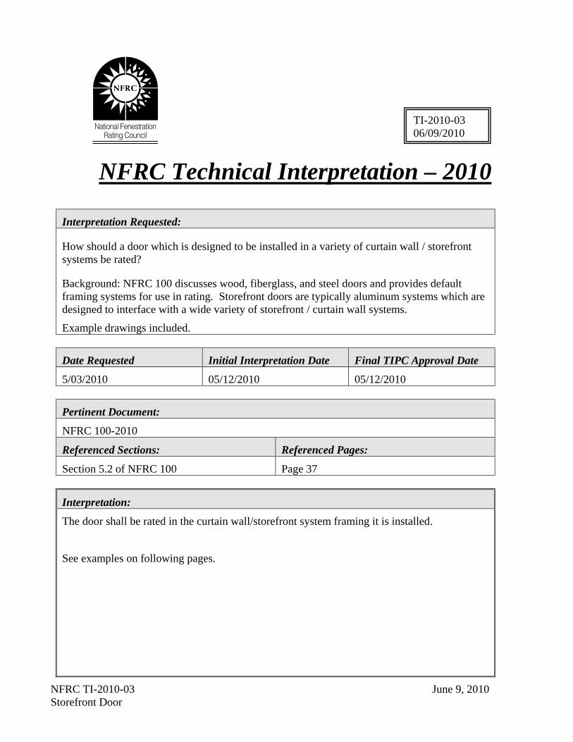
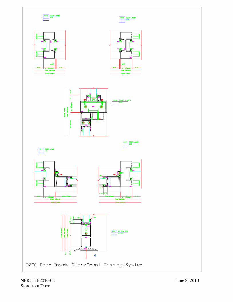
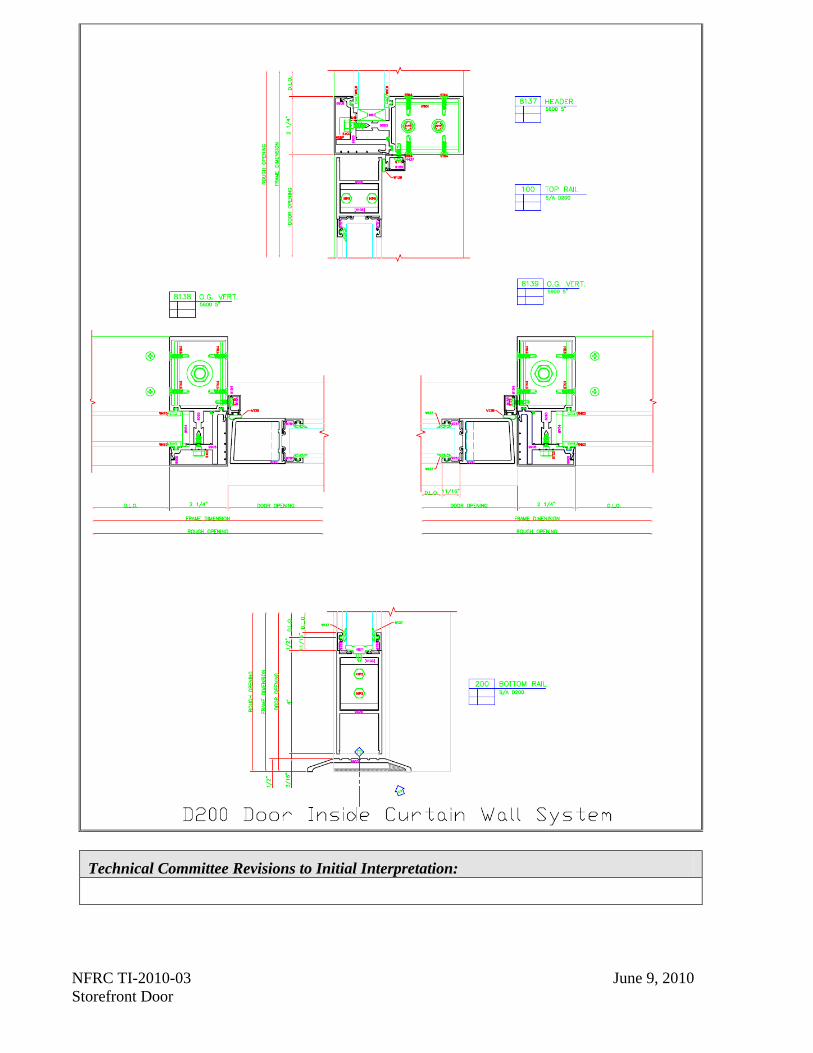
How should a door which is designed to be installed in a variety of curtain wall / storefront systems be rated?
Background: NFRC 100 discusses wood, fiberglass, and steel doors and provides default framing systems for use in rating. Storefront doors are typically aluminum systems which are designed to interface with a wide variety of storefront / curtain wall systems.
Example drawings included.
Date Requested Initial Interpretation Date Final TIPC Approval Date
5/03/2010 05/12/2010 05/12/2010
Pertinent Document:
NFRC 100-2010
Referenced Sections: Referenced Pages:
Section 5.2 of NFRC 100 Page 37
Interpretation:
The door shall be rated in the curtain wall/storefront system framing it is installed.
See examples on following pages.
TI-2010-03 06/09/2010
NFRC TI-2010-03 June 9, 2010 Storefront Door
NFRC TI-2010-03 June 9, 2010 Storefront Door
NFRC TI-2010-03 June 9, 2010 Storefront Door
Technical Committee Revisions to Initial Interpretation:
NFRC TI-2010-04 June 21, 2010 Vents in Glazed Wall Systems
NFRC Technical Interpretation – 2010 Interpretation Requested:
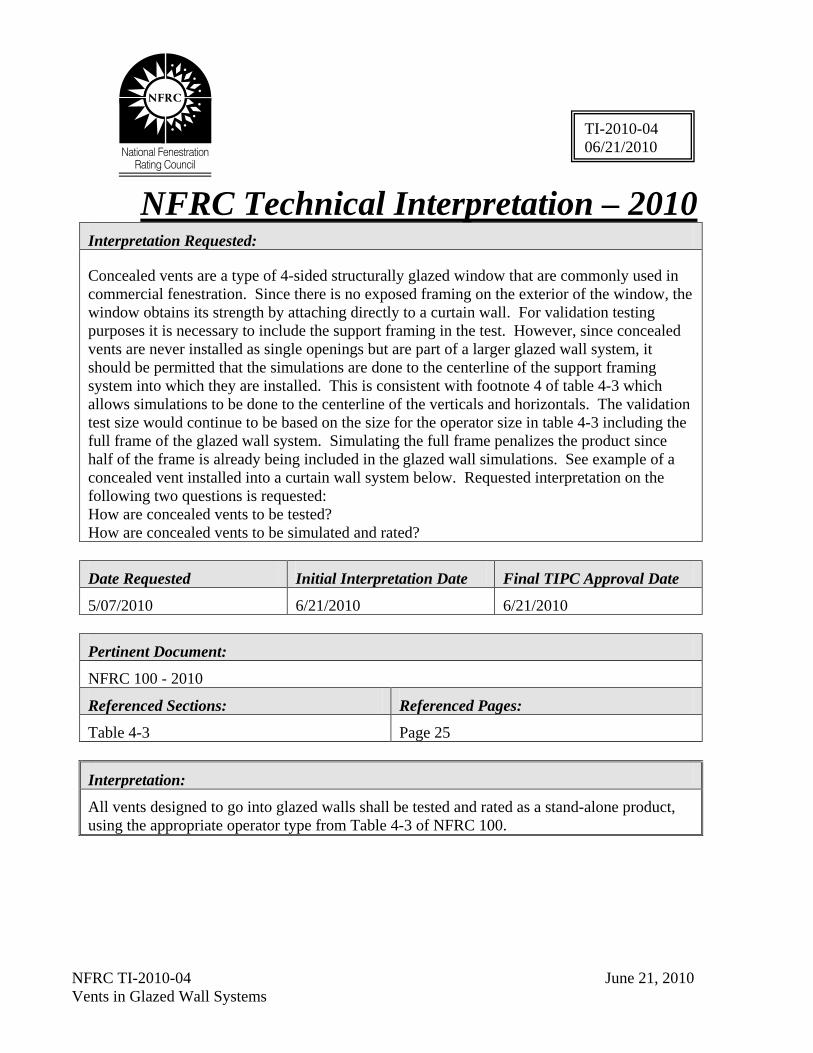
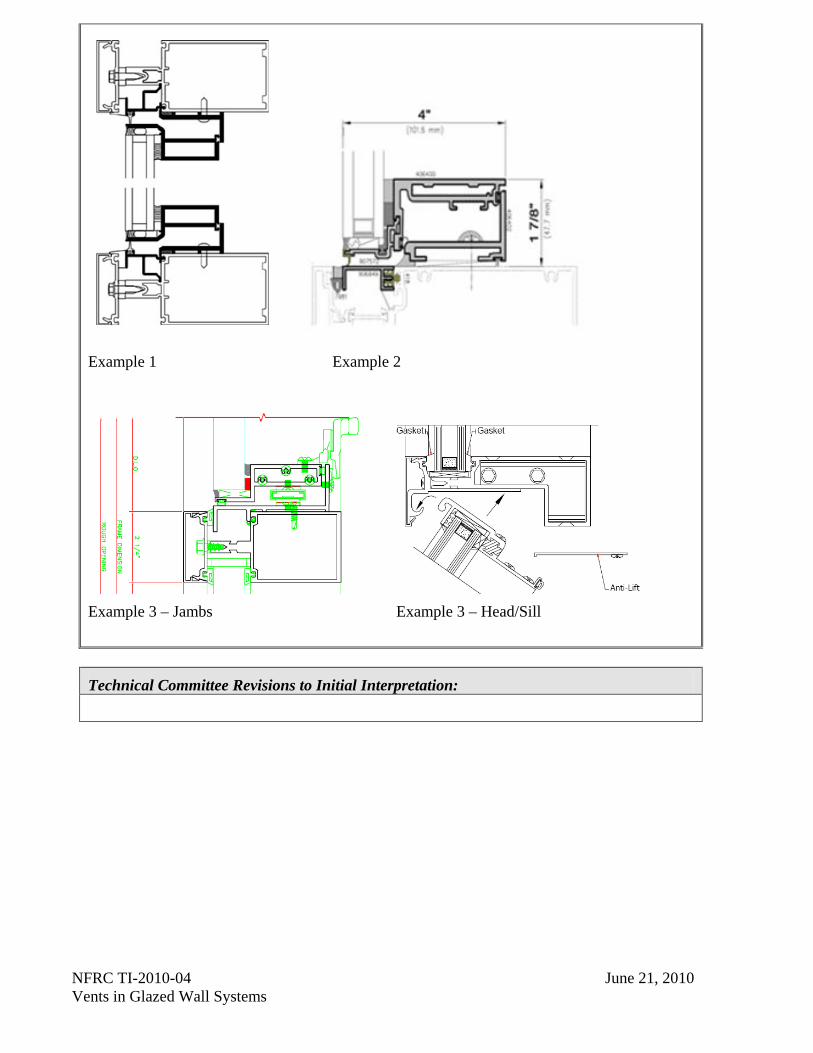
Concealed vents are a type of 4-sided structurally glazed window that are commonly used in commercial fenestration. Since there is no exposed framing on the exterior of the window, the window obtains its strength by attaching directly to a curtain wall. For validation testing purposes it is necessary to include the support framing in the test. However, since concealed vents are never installed as single openings but are part of a larger glazed wall system, it should be permitted that the simulations are done to the centerline of the support framing system into which they are installed. This is consistent with footnote 4 of table 4-3 which allows simulations to be done to the centerline of the verticals and horizontals. The validation test size would continue to be based on the size for the operator size in table 4-3 including the full frame of the glazed wall system. Simulating the full frame penalizes the product since half of the frame is already being included in the glazed wall simulations. See example of a concealed vent installed into a curtain wall system below. Requested interpretation on the following two questions is requested:
How are concealed vents to be tested? How are concealed vents to be simulated and rated?
Date Requested Initial Interpretation Date Final TIPC Approval Date
5/07/2010 6/21/2010 6/21/2010
Pertinent Document:
NFRC 100 - 2010
Referenced Sections: Referenced Pages:
Table 4-3 Page 25
Interpretation:
All vents designed to go into glazed walls shall be tested and rated as a stand-alone product, using the appropriate operator type from Table 4-3 of NFRC 100.
TI-2010-04 06/21/2010
NFRC TI-2010-04 June 21, 2010 Vents in Glazed Wall Systems
Example 1 Example 2
Example 3 – Jambs Example 3 – Head/Sill
Technical Committee Revisions to Initial Interpretation:
NFRC TI-2010-05 July 23, 2010 Exterior Bi-fold Doors (Folding Walls) Revised November 1, 2010
NFRC Technical Interpretation – 2010
Interpretation Requested:
Can a manufacturer obtain U-factor, SHGC and VT ratings for exterior bi-fold doors (a.k.a. folding walls) using NFRC’s current technical procedures (NFRC 100 and 200)? If so, how?
Date Requested Initial Interpretation Date Final TIPC Approval Date
6/23/10 7/15/2010 7/15/2010
Pertinent Document:
NFRC 100-2010, NFRC 200-2010
Referenced Sections: Referenced Pages:
NFRC 100, Section 5.2
NFRC 200, Section 2.1
Page 36
Page 2
Interpretation:
Yes, exterior bi-fold doors (folding walls) shall be rated and tested as a single or double swinging door.
Technical Committee Revisions to Initial Interpretation:
The revision to this TI was a decision by the Board of Directors Steering Committee to change the term bi-fold doors to exterior bi-fold doors (a.k.a. folding walls).
TI-2010-05 07/23/2010 11/01/2010 Revised
NFRC TI-2010-07 October 25, 2010 Entry Door with Storm
NFRC Technical Interpretation – 2010
Interpretation Requested:
How is an Entry Door product (with and/or without glass lites) rated when supplied with a pre-installed storm door from the manufacturer?
Date Requested Initial Interpretation Date Final TIPC Approval Date
9/31/2010 10/25/2010 10/25/2010
Pertinent Document:
NFRC 100-2010
Referenced Sections: Referenced Pages:
NFRC 100, Section 5.2 Page 38
Interpretation:
The product shall be rated with the storm door and associated parts removed from the assembly, or as Test Only for each configuration.
Technical Committee Revisions to Initial Interpretation:
TI-2010-07 10/25/2010
NFRC TI-2010-08 December 8, 2010 Door Infill/Glazing Grouping
NFRC Technical Interpretation – 2010
Interpretation Requested:
If a manufacturer has simulated a full lite door and wishes to add the option of substituting an opaque infill system which contains panels or a combination panels and glazing for the existing glazing. May the manufacturer simulate the infill system utilizing the simplifications described in NFRC 100 Section 5.2.4 to reduce the number of individual products required to represent the product line and include the results of this simulation with the results of the existing full lite simulation?
Date Requested Initial Interpretation Date Final TIPC Approval Date
10/25/2010 12/08/2010 12/08/2010
Pertinent Document:
NFRC 100-2010
Referenced Sections: Referenced Pages:
NFRC 100, Section 5.2 and 5.2.4 Pages 39-41
Interpretation:
Yes. The manufacturer may model and rate single swing doors using WINDOW to calculate the full lite door per the model size, but may also use the Entry Door Spreadsheet methodology to calculate the ¾, ½, and ¼ lite options.
Technical Committee Revisions to Initial Interpretation:
TI-2010-08 12/08/2010
NFRC TI-2010-09 December 8, 2010 Entry Door Panel Sizes
NFRC Technical Interpretation – 2010
Interpretation Requested:
Are embossed panel, or stile and rail panel, doors/sidelights ¼ lite, ½ lite, ¾ lite and full lite sizes defined by Table 5.1 or NFRC 100 Section 5.2.6 Figure 5-1?
Date Requested Initial Interpretation Date Final TIPC Approval Date
10/25/2010 12/08/2010 12/08/2010
Pertinent Document:
NFRC 100-2010
Referenced Sections: Referenced Pages:
NFRC 100 Section 5.2, Table 5.1
NFRC 100 Figure 5-1 Pages 39-43
Interpretation:
It is defined by Table 5-1 when using the simplification option per section 5.2.5.1. If the simplification is not used, then the actual configuration of panel and glazing sizes shall be rated.
Technical Committee Revisions to Initial Interpretation:
TI-2010-09 12/08/2010
NFRC TI-2010-10 December 8, 2003 Trapped Air Modeling in Spacer System Reapproved December 8, 2010
NFRC Technical Interpretation – 2010
Interpretation Requested:
How do we model the trapped air spaces within any spacer system?
Date Requested Initial Interpretation Date Final TIPC Approval Date
10/30/2003 12/08/2003 12/08/2003 Reapproved 12/08/2010
Pertinent Document:
NFRC 100-2010
Referenced Sections: Referenced Pages:
NFRC 100, Section 4.3.1 Page 22
Interpretation:
Create a new solid material called “still air cavity” with a conductivity of 0.024 W/m-K.
Note: The 0.024 W/m-K is the same conductivity used in the 3-D modeling calculation for Bolts, etc.
Technical Committee Revisions to Initial Interpretation:
TI-2010-10 12/08/2010
NFRC TI-2010-11 July 30, 2004 Rating for Test Only Glazing without Frame Reapproved December 8, 2010
NFRC Technical Interpretation – 2010
Interpretation Requested:
How are corrugated plastic panels that are manufactured and installed without frames rated for U-factor and SHGC?
Date Requested Initial Interpretation Date Final TIPC Approval Date
06/21/2004 07/30/2004 07/30/2004 Reapproved 12/08/10
Pertinent Document:
NFRC 100-2010, NFRC 102-2010, NFRC 200-2010 and NFRC 201-2010
Referenced Sections: Referenced Pages:
NFRC 100-2010, Section 4.3.2.2 NFRC 200-2010, Section 2.1.1 & 4.6
Page 25 Pages 3 & 13
Interpretation:
U-factor – Section 4.3.2.2 of NFRC 100-2010 shall be adhered to.
SHGC – A specimen sized per 1000mm x 1000mm shall be tested per NFRC 201 as center-of-glazing. The SHGC of the product shall be the tested center-of-glazing.
Technical Committee Revisions to Initial Interpretation:
TI-2010-11 07/30/2004
NFRC TI-2010-12 August 11, 2005 Stacked Frame Reapproved December 8, 2010
NFRC Technical Interpretation – 2010 Interpretation Requested:
Are additional profiles attached to the perimeter of a window frame to be modeled as part of the same product line? Is it an individual product within a product line?
Date Requested Initial Interpretation Date Final TIPC Approval Date
07/21/2005 07/25/2005 08/11/2005 Reapproved 12/08/2010
Pertinent Document:
NFRC 100-2010
Referenced Sections: Referenced Pages:
Section 4.2.5.B Page 20
Interpretation:
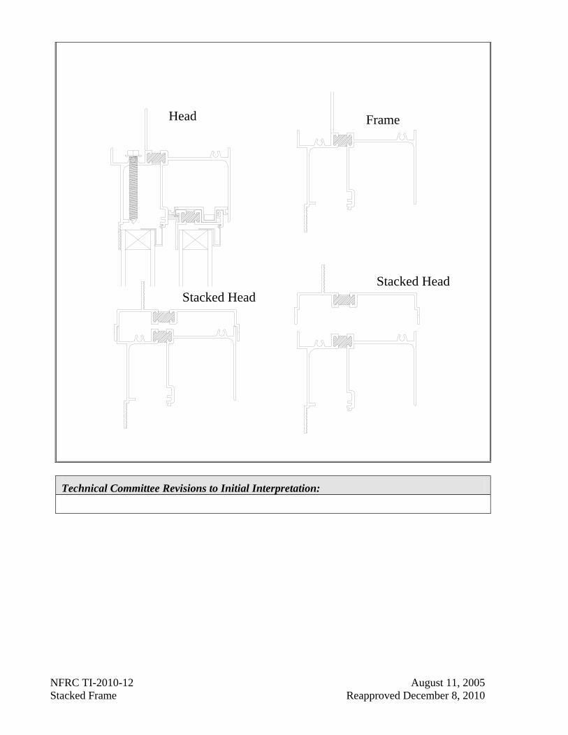
No. The fenestration product with the additional attached profile is to be treated as a separate product line. (See the example below)
TI-2010-12 08/11/2005
NFRC TI-2010-12 August 11, 2005 Stacked Frame Reapproved December 8, 2010
Head Frame
Stacked HeadStacked Head
Technical Committee Revisions to Initial Interpretation:
NFRC TI-2010-13 March 15, 2006 Modeling of Non-Circular Diffuser for TDD Reapproved December 8, 2010
NFRC Technical Interpretation – 2010 Interpretation Requested:
What are the differences (if any) in the simulation procedure for Tubular Daylighting Devices which have a square bottom diffuser section? Is there any variation to account for the diffuser section being larger than the tube diameter?
Date Requested Initial Interpretation Date Final TIPC Approval Date
01/19/2006 03/15/2006 03/15/2006 Reapproved 12/08/2010
Pertinent Document:
NFRC 100-2010 and NFRC 200-2010
Referenced Sections: Referenced Pages:
Table 4-3 Section 5.4
Page 26 Page 55
Interpretation:
For non circular diffuser, for simulation use the circular diffuser with surface area equal to actual non circular diffuser surface area.
Technical Committee Revisions to Initial Interpretation:
TI-2010-13 03/15/2006
NFRC TI-2010-14 March 15, 2006 Grouping Between Glass Shades COG Options Reapproved December 8, 2010
NFRC Technical Interpretation – 2010 Interpretation Requested:
Can one group the test-only COG options including between-glass shades based on the known COG properties without between-glass shades?
Date Requested Initial Interpretation Date Final TIPC Approval Date
03/13/2006 03/15/2006 03/15/2006 Reapproved 12/08/2010
Pertinent Document:
NFRC 100-2010 and NFRC 200-2010
Referenced Sections: Referenced Pages:
Section 4.2.4.1 Section 4.2.3
Page 18 Page 8
Interpretation:
Yes.
U-Factor: For each group, the group leader shall be the tested COG option including the between-glass shade corresponding to the simulated COG option (without the between-glass shade) with the highest COG U-value in accordance with the section 4.2.4.1 in NFRC 100.
SHGC: For each group, the group leader shall be the tested COG option including the between-glass shade corresponding to the simulated COG option (without the between-glass shade) in accordance with the Section 4.2.3 and rules of Table 4-1 in NFRC 200.
Technical Committee Revisions to Initial Interpretation:
TI-2010-14 03/15/2006

NFRC TI-2010-15 July 10, 2006 Largest CTS Size Reapproved December 8, 2010
NFRC Technical Interpretation – 2010 Interpretation Requested:
What is the size for the large Calibration Transfer Standards (CTS) if a lab has to test 2000mm by 2000mm size sample?
Date Requested Initial Interpretation Date Final TIPC Approval Date
05/23/2006 06/19/2006 07/10/2006 Reapproved 12/08/2010
Pertinent Document:
NFRC 102-2010
Referenced Sections: Referenced Pages:
5.1.3 (A) 8
Interpretation:
For the largest CTS the minimum width shall be 72” and the minimum height shall be 80”. A laboratory is allowed to build a larger size CTS at their discretion.
Technical Committee Revisions to Initial Interpretation:
TI-2010-15 07/11/2006
NFRC TI-2010-16 January 4, 2007 Simulation of a Single Lite Glazed Wall Reapproved December 8, 2010
NFRC Technical Interpretation – 2004 Interpretation Requested:
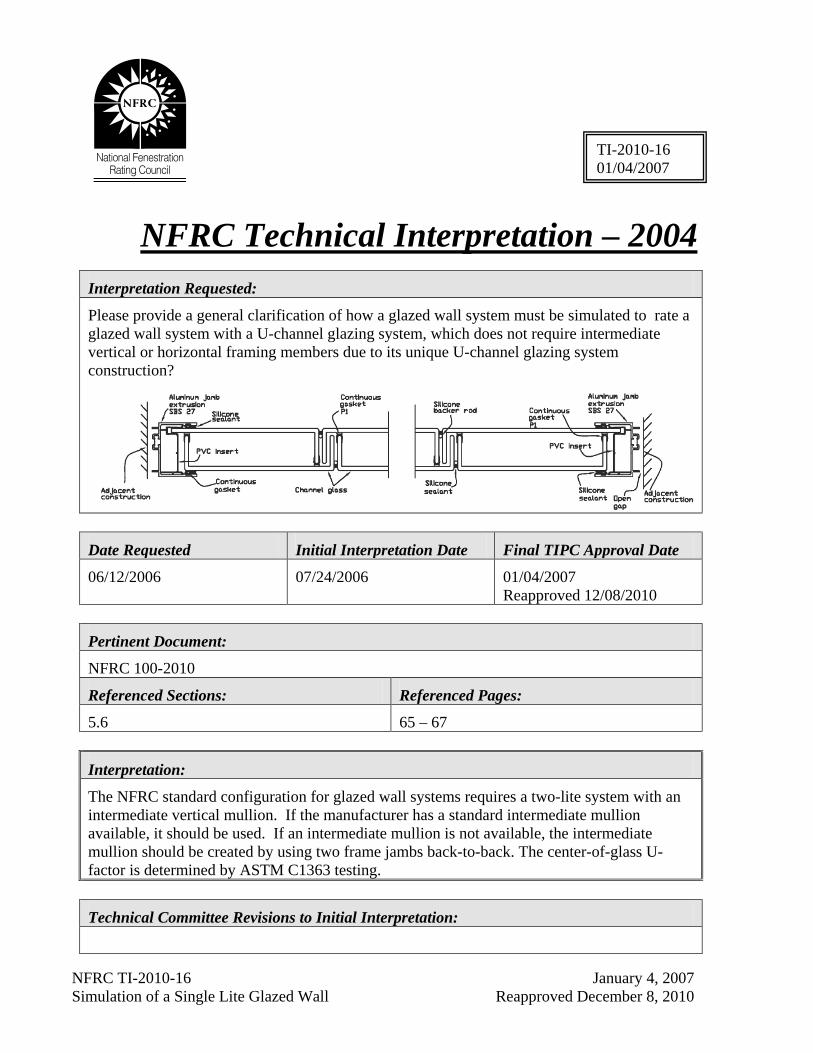
Please provide a general clarification of how a glazed wall system must be simulated to rate a glazed wall system with a U-channel glazing system, which does not require intermediate vertical or horizontal framing members due to its unique U-channel glazing system construction?
Date Requested Initial Interpretation Date Final TIPC Approval Date
06/12/2006 07/24/2006 01/04/2007 Reapproved 12/08/2010
Pertinent Document:
NFRC 100-2010
Referenced Sections: Referenced Pages:
5.6 65 – 67
Interpretation:
The NFRC standard configuration for glazed wall systems requires a two-lite system with an intermediate vertical mullion. If the manufacturer has a standard intermediate mullion available, it should be used. If an intermediate mullion is not available, the intermediate mullion should be created by using two frame jambs back-to-back. The center-of-glass U-factor is determined by ASTM C1363 testing.
Technical Committee Revisions to Initial Interpretation:
TI-2010-16 01/04/2007
NFRC TI-2010-17 January 4, 2007 Selecting Intermediate Members for CW Reapproved December 8, 2010
NFRC Technical Interpretation – 2010 Interpretation Requested:
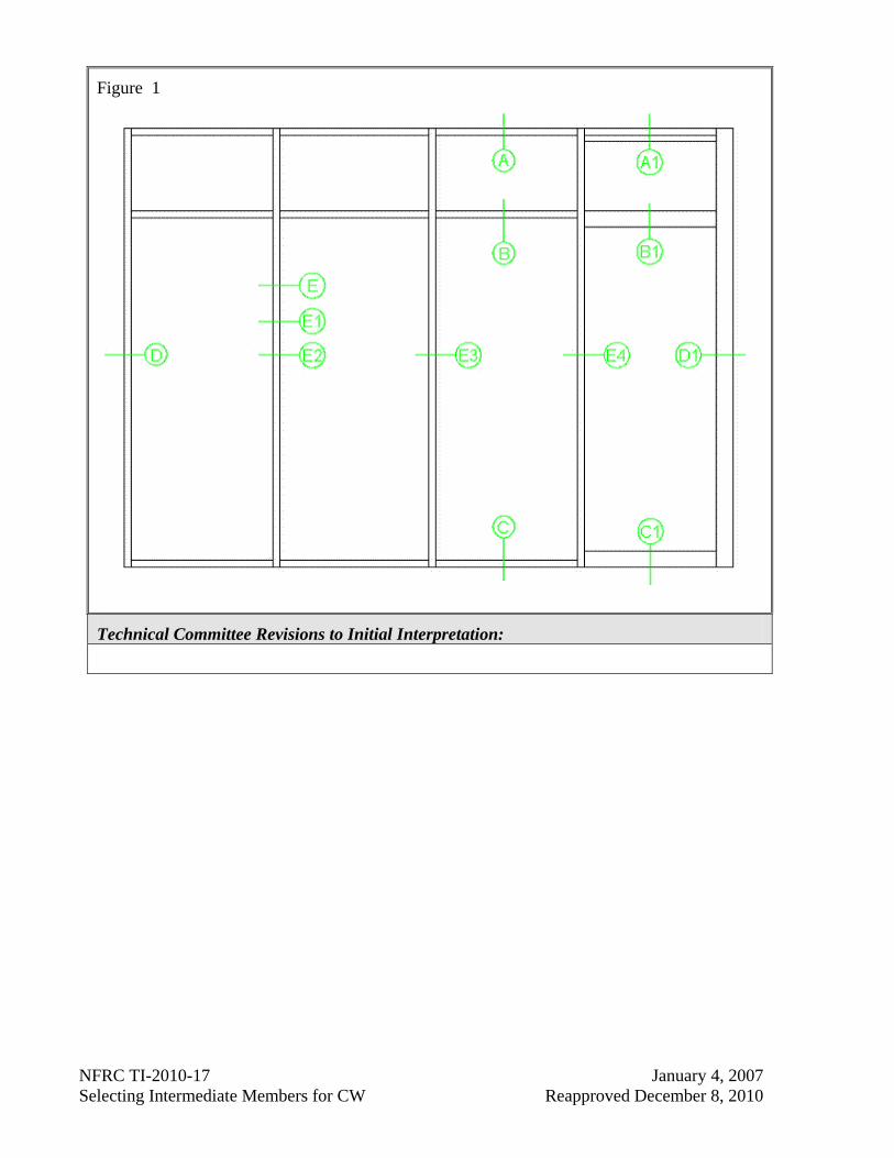
Please provide general clarification on modeling a store front system given in Figure 1 and how to select a typical cross section for modeling the intermediate verticals as jamb in a window wall system.
Date Requested Initial Interpretation Date Final TIPC Approval Date
10/05/2006 10/25/2006 01/04/2007 Reapproved 12/08/2010
Pertinent Document:
NFRC 100-2010
Referenced Sections: Referenced Pages:
Table 4-3, Footnote #5 & Section 5.6 26; 65 – 67
Interpretation:
The store front system shall be simulated as a Glazed Window Walls System. As per footnote #5, Window Walls shall be simulated and tested with intermediate verticals as jamb (using half of jamb for U-factor tag) and standard head and sill members. If the intermediate verticals are not the same, then they can either be simulated as different product lines, or grouped, if applicable. The horizontals in the storefront system, other than the door transom, shall be ignored. The door and transom, if present shall be each simulated separately. For door and transom use standard jamb definition (i.e., full U-factor tag).
TI-2010-17 01/04/2007
NFRC TI-2010-17 January 4, 2007 Selecting Intermediate Members for CW Reapproved December 8, 2010
Figure 1
Technical Committee Revisions to Initial Interpretation:
NFRC TI-2006-18 January 4, 2007 Selecting Door Lite Size for Shading Device Reapproved December 8, 2010
NFRC Technical Interpretation – 2010 Interpretation Requested:
For doors with integral shading devices, how do we rate the multiple sizes - ¼, ½, ¾, and full?
Date Requested Initial Interpretation Date Final TIPC Approval Date
12/01/2006 01/04/2007 01/04/2007 Reapproved 12/08/2010
Pertinent Document:
NFRC 100-2010& NFRC 200-2010
Referenced Sections: Referenced Pages:
NFRC 100, Sections 2.1.H & 4.2.2.D NFRC 200, Section 2.1.1.A
3 & 16 3
Interpretation:
Determine the least deviation from 1 meter by 1 meter (39” by 39”) and the resultant conductance value can be used for all product types specified in Table 1 of NFRC 100.
Technical Committee Revisions to Initial Interpretation:
TI-2010-18 01/04/2007
NFRC TI-2010-19 May 6, 2008 Rating Non-Standard TDD Reapproved December 8, 2010
NFRC Technical Interpretation – 2010 Interpretation Requested:
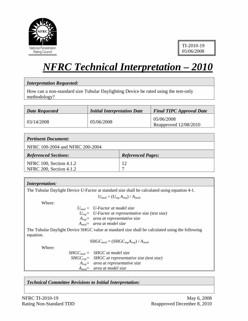
How can a non-standard size Tubular Daylighting Device be rated using the test-only methodology?
Date Requested Initial Interpretation Date Final TIPC Approval Date
03/14/2008 05/06/2008 05/06/2008 Reapproved 12/08/2010
Pertinent Document:
NFRC 100-2004 and NFRC 200-2004
Referenced Sections: Referenced Pages:
NFRC 100, Section 4.1.2 NFRC 200, Section 4.1.2
12 7
Interpretation: The Tubular Daylight Device U-Factor at standard size shall be calculated using equation 4-1.
Umod = (Urep Arep) / Amod
Where: Umod = U-Factor at model size Urep= U-Factor at representative size (test size) Arep= area at representative size Amod= area at model size The Tubular Daylight Device SHGC value at standard size shall be calculated using the following equation.
SHGCmod = (SHGCrepArep) / Amod
Where: SHGCmod = SHGC at model size SHGCrep= SHGC at representative size (test size) Arep= area at representative size Amod= area at model size
Technical Committee Revisions to Initial Interpretation:
TI-2010-19 05/06/2008
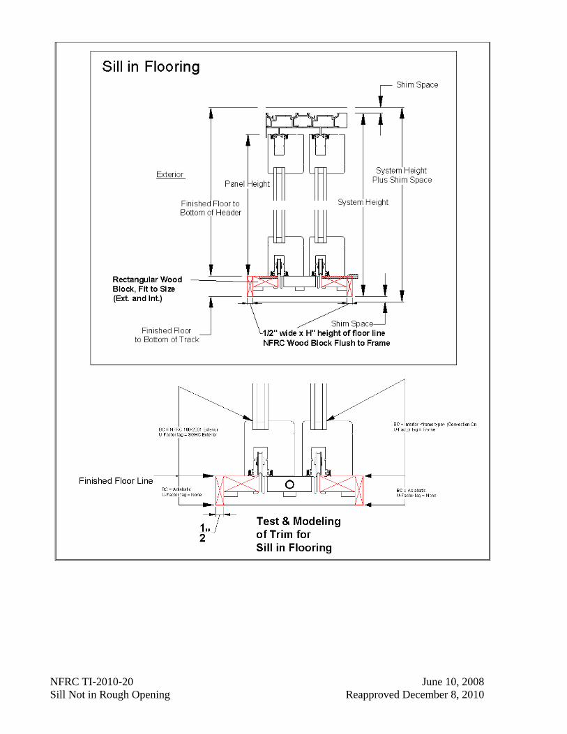
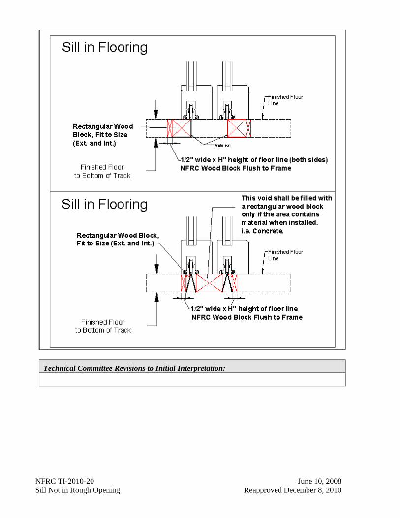
NFRC TI-2010-20 June 10, 2008 Sill Not in Rough Opening Reapproved December 8, 2010
NFRC Technical Interpretation – 2010 Interpretation Requested:
If the sill of a sliding glass door is designed set into the building; installed so that it extends beyond the rough opening, is it considered an appendage and therefore not modeled?
Date Requested Initial Interpretation Date Final TIPC Approval Date
04/02/2008 04/10/2008 06/10/2008 Reapproved 12/08/2010
Pertinent Document:
NFRC 100-2010
Referenced Sections: Referenced Pages:
Section 4.2.5.A, 4.2.5.B Page 20
Interpretation:
No, although the integral framing member (in this case the sill) extends beyond the rough opening and is not exposed after installation, it shall be modeled in the following manner:
A rectangular wood block (pine or equivalent) ½” x H” (height from the bottom of the sill cavity to the finish floor line) shall be placed from at the edge of the frame on both the exterior and interior.
A rectangular wood block shall be sized to fit the exterior and interior area void created between the ½” block and the sill roller track.
If applicable, any remaining center void that is intended to be filled with material (i.e., concrete) when the unit is installed, a rectangular wood block shall be sized to fit the area.
See accompanying drawings:
TI-2010-20 03/24/2003
NFRC TI-2010-20 June 10, 2008 Sill Not in Rough Opening Reapproved December 8, 2010
NFRC TI-2010-20 June 10, 2008 Sill Not in Rough Opening Reapproved December 8, 2010
Technical Committee Revisions to Initial Interpretation:
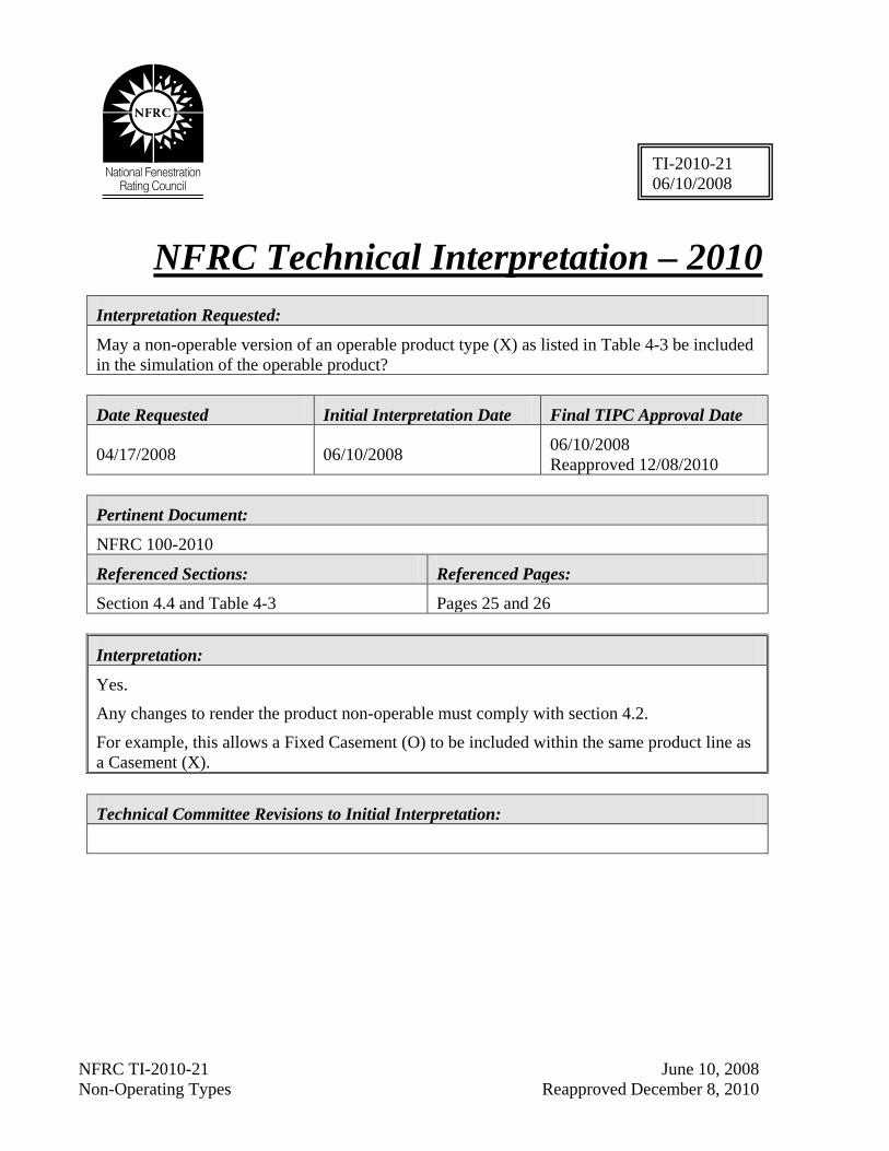
NFRC TI-2010-21 June 10, 2008 Non-Operating Types Reapproved December 8, 2010
NFRC Technical Interpretation – 2010 Interpretation Requested:
May a non-operable version of an operable product type (X) as listed in Table 4-3 be included in the simulation of the operable product?
Date Requested Initial Interpretation Date Final TIPC Approval Date
04/17/2008 06/10/2008 06/10/2008 Reapproved 12/08/2010
Pertinent Document:
NFRC 100-2010
Referenced Sections: Referenced Pages:
Section 4.4 and Table 4-3 Pages 25 and 26
Interpretation:
Yes.
Any changes to render the product non-operable must comply with section 4.2.
For example, this allows a Fixed Casement (O) to be included within the same product line as a Casement (X).
Technical Committee Revisions to Initial Interpretation:
TI-2010-21 06/10/2008
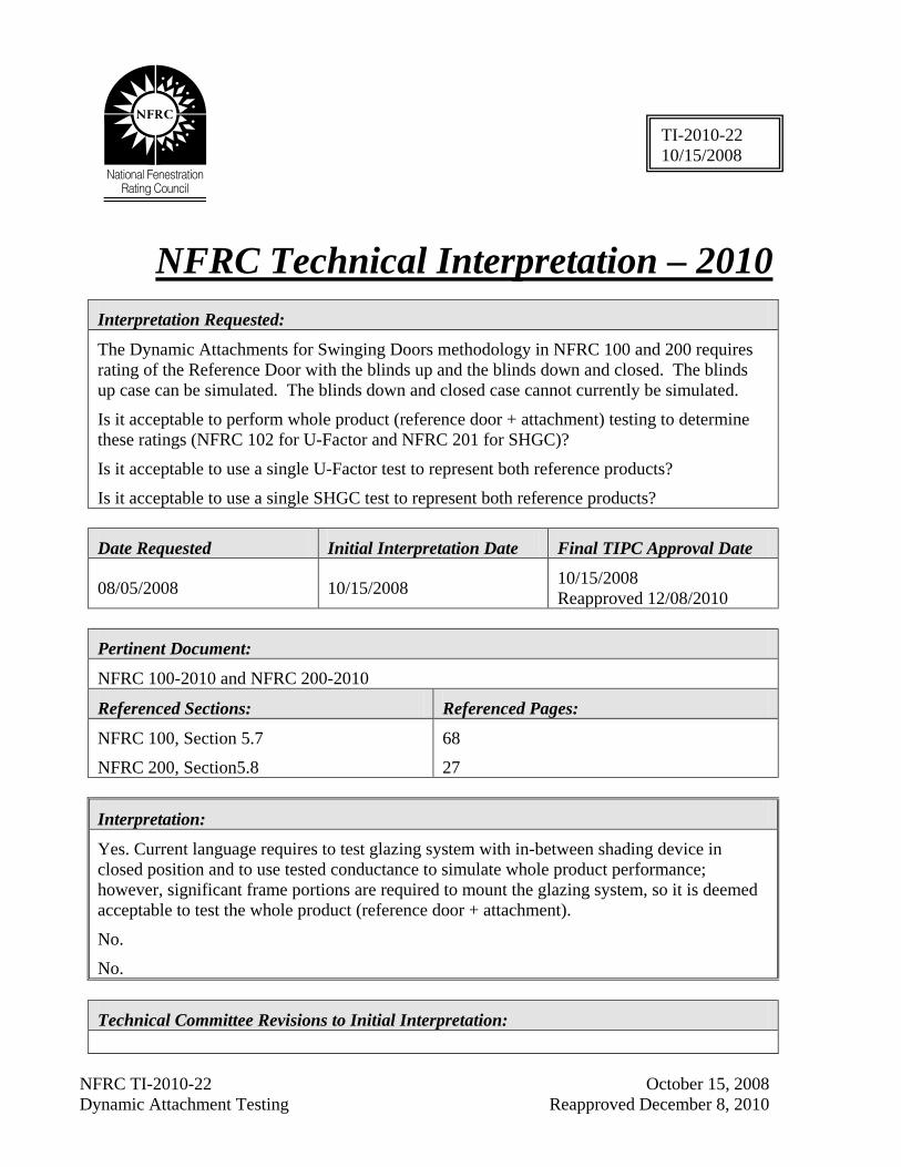
NFRC TI-2010-22 October 15, 2008 Dynamic Attachment Testing Reapproved December 8, 2010
NFRC Technical Interpretation – 2010 Interpretation Requested:
The Dynamic Attachments for Swinging Doors methodology in NFRC 100 and 200 requires rating of the Reference Door with the blinds up and the blinds down and closed. The blinds up case can be simulated. The blinds down and closed case cannot currently be simulated.
Is it acceptable to perform whole product (reference door + attachment) testing to determine these ratings (NFRC 102 for U-Factor and NFRC 201 for SHGC)?
Is it acceptable to use a single U-Factor test to represent both reference products?
Is it acceptable to use a single SHGC test to represent both reference products?
Date Requested Initial Interpretation Date Final TIPC Approval Date
08/05/2008 10/15/2008 10/15/2008 Reapproved 12/08/2010
Pertinent Document:
NFRC 100-2010 and NFRC 200-2010
Referenced Sections: Referenced Pages:
NFRC 100, Section 5.7
NFRC 200, Section5.8
68
27
Interpretation:
Yes. Current language requires to test glazing system with in-between shading device in closed position and to use tested conductance to simulate whole product performance; however, significant frame portions are required to mount the glazing system, so it is deemed acceptable to test the whole product (reference door + attachment).
No.
No.
Technical Committee Revisions to Initial Interpretation:
TI-2010-22 10/15/2008
NFRC TI-2010-23 June 16, 2009 Thermal Conductivity of Non-Homogeneous Specimens Reapproved December 8, 2010
NFRC Technical Interpretation – 2010
Interpretation Requested:
Can ASTM C518 be used to measure the effective thermal conductivity of non-homogeneous specimens, such as composite spacer products or materials that cannot be extruded in sufficient thickness, which cannot otherwise be simulated due to material component construction and limitations of the NFRC software?
Date Requested Initial Interpretation Date Final TIPC Approval Date
04/24/2009 06/16/2009 06/16/2009 Reapproved 12/08/2010
Pertinent Document:
NFRC 100-2010 NFRC 101-2010
Referenced Sections: Referenced Pages: NFRC 100, Section 4.3.1.B NFRC 101, Section 5
22 8
Interpretation:
Yes, ASTM C-518 testing is acceptable for obtaining effective thermal conductivity values for materials and components that cannot be simulated and/or provided as a homogeneous specimen for testing. Limitations to this allowance are: As stated in NFRC 101, three (3) samples shall be tested and the tested values shall be within 10%. The test specimen must be assembled of parallel lengths of the sample material having thickness no less than 12.7 mm (1/2”) and that no gaps exist between the lengths of material that may allow for air within the test specimen assembly. In cases where the chamber needs to be protected or the specimen cannot be properly sealed, the specimen shall be prepared sandwiched between two pieces of ¼” thick glass. Orientation of the test specimen material is such that the heat flux in the test assembly is in the same direction across the test specimen assembly as when the component is installed in an
TI-2010-23 06/16/2009
NFRC TI-2010-23 June 16, 2009 Thermal Conductivity of Non-Homogeneous Specimens Reapproved December 8, 2010
insulating glass unit. The test specimen assembly construction is such that the heat flux is predominantly uniform across the test area and that areas of localized heat flux variation is minimized.
Technical Committee Revisions to Initial Interpretation:
NFRC TI-2010-24 August 18, 2009 COG SHGC of Integral Screen Systems Reapproved December 8, 2010
NFRC Technical Interpretation – 2010 Interpretation Requested:
Can a total product test be used to determine a center-of-glass SHGC (SHGCcog)? When a total product is tested for SHGC with an integral blind or solar screen, can we
calculate the SHGCcog?
Can the calculated SHGCcog be used for other product lines with the same glazing and integral blind or solar screen?
Date Requested Initial Interpretation Date Final TIPC Approval Date
08/10/2009 08/18/2009 08/18/2009 Reapproved 12/08/2010
Pertinent Document:
NFRC 200-2010
Referenced Sections: Referenced Pages: Sections 4.5 & 4.7 Pages 10 & 13
Interpretation: Yes, only in the case that a COG test cannot be performed and the sample size shall include a
1m x 1m glass area, as required per TI-2004-07. The center-of-glass SHGC shall be calculated as follows:
SHGCcog = (SHGCtotal - SHGC0 ) / (SHGC1-SHGC0), where:
SHGCtotal will be from the NFRC 201 test, and the SHGC0 and SHGC1 will be from Window 5.2 for the product with custom size (same size as the NFRC 201 test sample).
Yes, this only applies when the integral blind or solar screen is between the panes of glass as defined in NFRC 100, Section 2.1.H.
Yes. As long as interpretations in #1 and #2 are applied.
Technical Committee Revisions to Initial Interpretation:
TI-2010-24 08/18/2009
NFRC TI-2010-25 December 10, 2009 Single vs Dual Seal Spacer Definition March 3, 2010 Revised Reapproved December 8, 2010
NFRC Technical Interpretation – 2010 Interpretation Requested: Clarification of Dual Seal (D) vs. Single Seal (S) for reporting of spacer codes.
The NFRC now requires that the simulation and thermal test labs upload report summaries to the NFRC website. If the simulation and test lab validations do not match exactly, the uploads are rejected by the IA and a new corrected upload is required from each lab.
Recently, there have been rejections of uploads from IA’s due to non-matching spacer codes between simulation and validation labs, specifically with the use of (S) vs. (D). Thus, it is requested that there be a clear definition made by the NFRC.
(1) When there is only one material type of sealant on both the sides and bottom of the spacer, would the simulation and test lab report a single sealed or dual sealed spacer system?
(2) When there are two different material types of sealant applied to a spacer would the simulation and test lab report this as a dual seal spacer system?
Date Requested Initial Interpretation Date Final TIPC Approval Date
11/17/2009 12/07/2009 12/07/2009 Revised 03/03/2010 Reapproved 12/08/2010
Pertinent Document:
Simulation Manual (November 2010) & Certified Products Director 2.0 Simulation Lab User's Manual
Referenced Sections: Referenced Pages: Simulation Manual, Section 2.7 Simulation Lab User's Manual, Section 3.3
Page 2-14 Page 7
Interpretation: (1) In the simulation manual, section 2.7, it states that there is a primary seal (edge of spacer to glass) that helps to hold the unit together and to prevent moisture intrusion and that a secondary seal (below spacer) is used to provide structural strength. It does not state that the sealant needs to be two different materials in order to be considered a dual sealed spacer.
TI-2010-25 12/10/2009 03/03/2010 Revised

NFRC TI-2010-25 December 10, 2009 Single vs Dual Seal Spacer Definition March 3, 2010 Revised Reapproved December 8, 2010
Thus, if a spacer is sealed both on the sides and below the spacer, it should be reported as a dual sealed spacer.
(2) If a spacer has more than one type of sealant material it will automatically be considered a dual sealed spacer.
Technical Committee Revisions to Initial Interpretation:
The revision to this TI was to add question #2, with corresponding answer.
NFRC TI-2010-26 March 31, 2004 Sidelight Scaling Reapproved March 15, 2011
NFRC Technical Interpretation – 2010
Interpretation Requested:
If a manufacturer does not build an embossed sidelight or raised panel sidelight product in a size near the NFRC Table 4-3 size how does the simulator determine the daylight opening/panel width and height dimensions for the standard NFRC size?
Date Requested Initial Interpretation Date Final TIPC Approval Date
02/23/2004 03/29/2004 03/29/2004 Reapproved 03/15/2011
Pertinent Document:
NFRC 100-2010 and NFRC 200-2010
Referenced Sections: Referenced Pages:
NFRC 100 Table 4-3
NFRC 100 Figures 5-2a, 5-2b, 5-3
Page 26
Pages 4-46
Interpretation:
The stile and rail (PFD) dimensions are held constant and the panel (PFD) dimensions are equally adjusted to account for the difference between the as built and as rated sizes.
Technical Committee Revisions to Initial Interpretation:
TI-2010-26 03/31/2004 03/15/2011 Revised
NFRC TI-2011-01 February 15, 2011 CMA Frame Grouping
NFRC Technical Interpretation – 2011 Interpretation Requested:
Grouping a frame component in CMA states that change in frame length perpendicular to the fenestration plane is allowed. Table 5.9.3 for aluminum products states that the maximum length is the group leader. When an aluminum unit is being lengthened solely by increasing the length of the thermal break, (see diagram below) should the group leader be determined by the component with the highest heat loss?
Date Requested Initial Interpretation Date Final TIPC Approval Date
01/27/2011 02/15/2011 02/15/2011
Pertinent Document:
NFRC 100-2010
Referenced Sections: Referenced Pages:
NFRC 100, Section 5.9.2
NFRC 100, Table 5.9.3
85
86
Interpretation: Frame grouping in NFRC 100 Section 5.9.5.2 for metallic frames shall only apply when the width and material of any thermal break (if present) does not change.
Technical Committee Revisions to Initial Interpretation:
TI-2011-01 02/15/2011
NFRC TI-2011-02 March 15, 2011 Skylights in CMAST
NFRC Technical Interpretation – 2011
Interpretation Requested:
According to the NFRC Simulation Manual when modeling a skylight, the Jamb members are to be assigned a cross section type of “Sill” and the gravity vector set to “Right”. In CMAST, the cross section type must be compatible with the location of the frame member, so a member with a cross-section type of Sill cannot be used as a Jamb when building a frame assembly in CMAST. What is the proper way to model these members in Therm, or import them to CMAST so they can be used correctly?
Date Requested Initial Interpretation Date Final TIPC Approval Date
03/09/2011 03/15/2011 03/15/2011
Pertinent Document:
CMAST Manual and Simulation Manual 6.3
Referenced Sections: Referenced Pages:
CMAST Manual, Section 3.6.2.1
Simulation Manual, Section 8.5.3
Page 61
Page 8-64
Interpretation: For products simulated at a slope, model the Jambs as Jamb and Vertical Intermediates as Vertical Meeting Rail so that the components can be used in CMAST. Set the gravity vector to the right.
Technical Committee Revisions to Initial Interpretation:
TI-2011-02 03/15/2011
NFRC TI-2011-03 April 21, 2011 Fabric Shade Between-the-Glass
NFRC Technical Interpretation – 2011
Interpretation Requested:
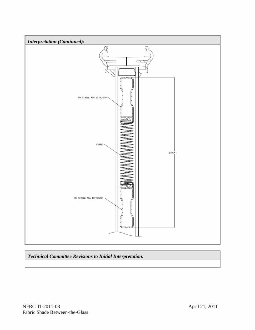
Can a fabric shade between the glass be simulated and rated in the fully retracted position?
Date Requested Initial Interpretation Date Final TIPC Approval Date
04/04/2011 04/21/2011 04/21/2011
Pertinent Document:
THERM 6.3 / WINDOW 6.3 NFRC Simulation Manual
Referenced Sections: Referenced Pages:
Section 8.11 Pages 8-119 through 8-129
Interpretation: Yes. The technique shown in Section 8.11 of the Simulation Manual shall be used, provided the shade system is designed to be stacked in the retracted position, with a solid block of “Cellulosic Fiber, Cotton Fiber” as the shade material in the model (See Model on next page)
TI-2011-03 04/21/2011
NFRC TI-2011-03 April 21, 2011 Fabric Shade Between-the-Glass
Interpretation (Continued):
Technical Committee Revisions to Initial Interpretation:
NFRC TI-2011-04 April 21, 2011 CMAST Frame Assembly Using Any Frame Component
NFRC Technical Interpretation – 2011 Interpretation Requested:
If an ACE needs to generate a certificate for a product using a Frame Assembly (FA), is the ACE limited to using Approved Frame Components from a single Framing Product Line (FPL)?
Date Requested Initial Interpretation Date Final TIPC Approval Date
04/20/2011 04/21/2011 04/21/2011
Pertinent Document:
CMAST Manual
Referenced Sections: Referenced Pages:
Appendix C Pages 144-146
Interpretation: No, the CMAST Manual, Section 3.5.2.1, allows assembly of an FA using any approved frame component.
Technical Committee Revisions to Initial Interpretation:
TI-2011-04 04/21/2011
NFRC TI-2011-05 May 31, 2011 Default Absorptance
NFRC Technical Interpretation – 2011 Interpretation Requested:
NFRC 200 4.7.A.iii requires that the Frame and Divider SHGC to be calculated with default absorptance values. Is it required to simulate all frame and divider products for U-factor using the same default absorptance values?
Date Requested Initial Interpretation Date Final TIPC Approval Date
05/02/2011 05/31/2011 05/31/2011
Pertinent Document:
NFRC 200
Referenced Sections: Referenced Pages:
Section 4.7.a.iii Pages 14
Interpretation: No, since U-factor is not affected by absorptance, only the individual products used to generate the Zero and One values called for in section 4.5 need to be calculated using the default absorptance values.
Technical Committee Revisions to Initial Interpretation:
TI-2011-05 05/31/2011
NFRC TI-2011-06 May 31, 2011 NFRC 102 Test Conditions
NFRC Technical Interpretation – 2011 Interpretation Requested:
Clarify the ambient test temperature conditions required for conducting an NFRC 102 test?
Date Requested Initial Interpretation Date Final TIPC Approval Date
05/09/2011 05/31/2011 05/31/2011
Pertinent Document:
NFRC 102-2010
Referenced Sections: Referenced Pages:
Section 7 Page 6
Interpretation:
The following temperature conditions shall be used:
Interior Temperature: 21.0 C (69.8 F) +/- 0.3C (+/- 0.5 F)
Exterior Temperature: -18.0 C (-0.4 F) +/- 0.3C (+/- 0.5 F)
The conditions above were published in NFRC 102-2004 and were inadvertently not included in NFRC 102-2010.
Technical Committee Revisions to Initial Interpretation:
TI-2011-06 05/31/2011
NFRC TI-2011-07 June 2, 2011 Default Sill for Steel Framed Door
NFRC Technical Interpretation – 2011 Interpretation Requested:
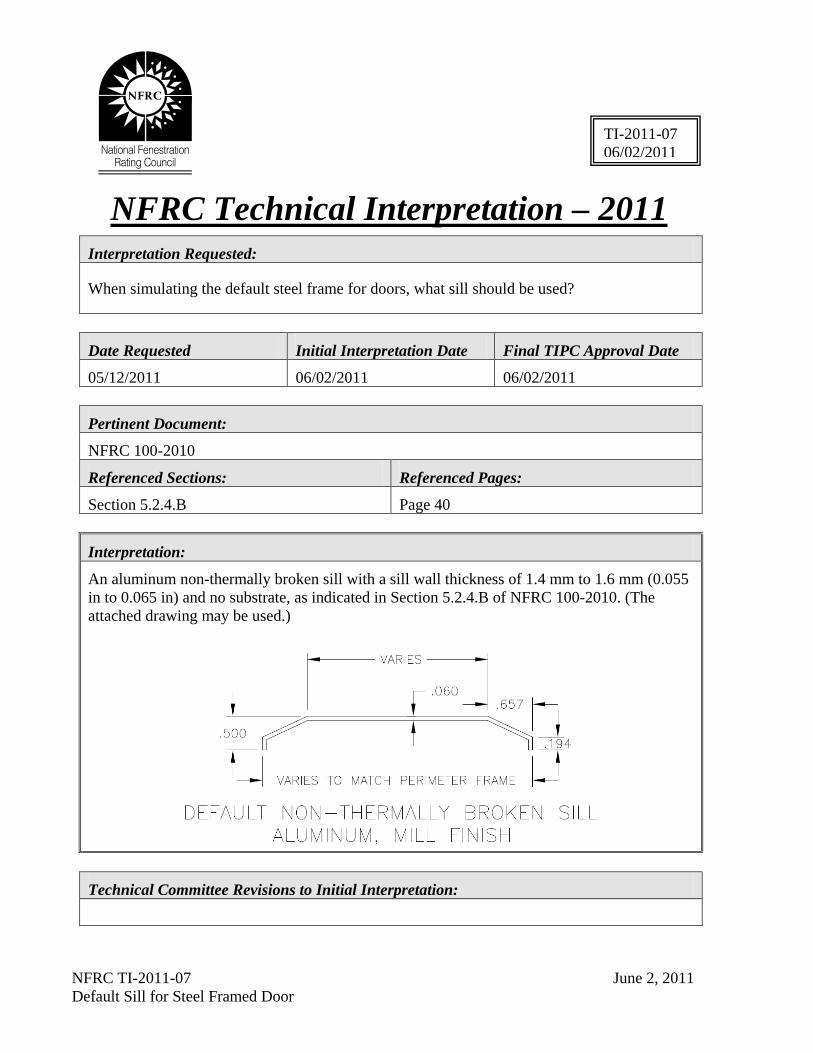
When simulating the default steel frame for doors, what sill should be used?
Date Requested Initial Interpretation Date Final TIPC Approval Date
05/12/2011 06/02/2011 06/02/2011
Pertinent Document:
NFRC 100-2010
Referenced Sections: Referenced Pages:
Section 5.2.4.B Page 40
Interpretation:
An aluminum non-thermally broken sill with a sill wall thickness of 1.4 mm to 1.6 mm (0.055 in to 0.065 in) and no substrate, as indicated in Section 5.2.4.B of NFRC 100-2010. (The attached drawing may be used.)
Technical Committee Revisions to Initial Interpretation:
TI-2011-07 06/02/2011
NFRC TI-2011-08 August 25, 2011 Dual Entry Doors
NFRC Technical Interpretation – 2011
Interpretation Requested:
Can a door with two slabs, one in front of the other, be rated by simulation assuming that the projected dimensions of the lite cutouts are the same for ¼, 1/2, 3/4 and full lites and assuming the product is sold as a system?
Date Requested Initial Interpretation Date Final TIPC Approval Date
03/01/2011 03/15/2011 08/25/2011
Pertinent Document:
NFRC100-2010, NFRC 200-2010, TI-2010-07
Referenced Sections: Referenced Pages:
NFRC 100-2010 (Section 5.2) NFRC 200-2010 (Section 5.2)
37-49 18
Interpretation:
Yes, so long as there is not a significant overlap (equal to or less than 25.4mm (1") between the vision area of one door and the opaque area of the other.
Technical Committee Revisions to Initial Interpretation:
TI-2011-08 08/25/2011
NFRC TI-2011-09 September 29, 2011 Modeling of Micro-foil Metals Revised October 25, 2011
NFRC Technical Interpretation – 2011
Interpretation Requested:
How does a simulator represent a very thin metal foil that is less than 0.005” thick?
Date Requested Initial Interpretation Date Final TIPC Approval Date
07/12/2011 08/25/2011 09/29/2011 Revised 10/25/2011
Pertinent Document:
NFRC Simulation Manual
Referenced Sections: Referenced Pages:
Section 6 6-1
Interpretation:
To simulate a very thin metal foil, increase the thickness by a multiple and divide its conductivity by the same multiple. Draw the foil at x times the thickness and use a conductivity equivalent to 1/x of the conductivity found in NFRC101. The modified thickness shall not exceed 0.005".
Technical Committee Revisions to Initial Interpretation: TIPC approved a revision on October 25, 2011 to allow the multiplier of the metal thickness to be any value rather than limiting it to an integer, as was initially interpreted.
TI-2011-09 09/29/2011
NFRC TI-2011-10 September 29, 2011 Swing Door Component Substitutions
NFRC Technical Interpretation – 2011
Interpretation Requested:
NFRC 100 Section 5 for Swing Doors makes multiple references to using default assemblies (frames, sills, door lite frames, etc). Are these considered component changes as defined in NFRC 100 Section 4.2.1.F even though the physical shapes may be different?
Date Requested Initial Interpretation Date Final TIPC Approval Date
08/18/2011 09/25/2011 09/25/2011
Pertinent Document:
NFRC 100
Referenced Sections: Referenced Pages:
Section 5 and 4.2.1 13, 36-50
Interpretation:
Yes
Technical Committee Revisions to Initial Interpretation:
TI-2011-10 09/29/2011
NFRC TI-2011-11 October 25, 2011 NFRC 102 e1 Variable
NFRC Technical Interpretation – 2011
Interpretation Requested: Clarify what value shall be entered for the variable, e1, for fenestration product testing conducted in accordance with NFRC 102?
Date Requested Initial Interpretation Date Final TIPC Approval Date
10/11/2011 10/25/2011 10/25/2011
Pertinent Document:
NFRC 102
Referenced Sections: Referenced Pages:
Section 7 6
Interpretation:
The surface emissivity of the Calibration Transfer Standard (CTS) shall be used for the variable e1 in all formulas where that variable is referenced.
Technical Committee Revisions to Initial Interpretation:
TI-2011-11 10/25/2011
NFRC TI-2011-12 November 29, 2011 Metallic Frame Boundary Conditions
NFRC Technical Interpretation – 2011
Interpretation Requested:
When simulating a product with a metallic frame, what interior boundary conditions and surface emissivities shall be applied?
Date Requested Initial Interpretation Date Final TIPC Approval Date
11/17/2011 11/29/2011 11/29/2011
Pertinent Document: NFRC 100-2010 NFRC 101-2010
Referenced Sections: Referenced Pages: Table 4-2 of NFRC 100 Appendix A, B, and C of NFRC 101
Page 24 Pages 18-26
Interpretation:
Non-thermally broken metallic frames shall use Aluminum, thermally improved metallic frames shall use Thermally Improved Aluminum; and, and thermally-broken metallic frames shall be use Thermally Broken Aluminum Boundary Conditions.
Metallic surfaces shall be assigned the emissivity per NFRC 101 for exposed, painted, or anodized as appropriate. Surfaces to be considered exposed shall follow the same rules as aluminum frames but with the emissivity appropriate for that material.
Technical Committee Revisions to Initial Interpretation:
TI-2011-12 11/29/2011
NFRC TI-2012-01 March 6, 2012 COG-Divider Grouping
NFRC Technical Interpretation – 2012
Interpretation Requested:
May a simulator group dividers based on COG values alone?
Date Requested Initial Interpretation Date Final TIPC Approval Date
11/28/2011 01/09/2012 03/06/2012
Pertinent Document: NFRC 100-2010
Referenced Sections: Referenced Pages: Section 4.2.4.1
Pages 18-19
Interpretation:
No, dividers may not be grouped by COG alone. Section 4.2.4.1 clearly requires that all COG options be identified and simulated. Any dividers that violate the 3mm rule for any glazing option shall be simulated in the lowest COG option that requires modeling.
Technical Committee Revisions to Initial Interpretation:
TI-2012-01 03/06/2012
NFRC TI-2012-02 April 10, 2012 Multiple SDL Bars in One Product Revised May 7, 2012
NFRC Technical Interpretation – 2012
Interpretation Requested: When a manufacturer combines both an SDL bar less than 25.4mm and one greater than 25.4mm in the same product, how is this product evaluated? Date Requested Initial Interpretation Date Final TIPC Approval Date
03/05/2012 04/10/2012 04/10/2012 05/07/2012
Pertinent Document:
NFRC 100 and 200 Referenced Sections: Referenced Pages:
NFRC 100, Section 4.2.4.1D
NFRC 200, Section 4.5C
Page 18
Page 11 Interpretation: An individual product that includes both SDL < 25.4mm and SDL ≥ 25.4mm shall be evaluated by grouping it with the SDL bar option ≥ 25.4 mm. Note: This TI does not apply to grilles-between-glass or true divided lites (TDL). Technical Committee Revisions to Initial Interpretation: The Board of Directors required clarification to address instances where the SDL bar option may be equal to 25.4mm. The interpretation was revised to read ≥ 25.4mm to account for that omission.
TI-2012-02 03/05/2012 05/07/2012 Revised

NFRC TI-2012-03 April 10, 2012 Frame Absorptance in CMAST
NFRC Technical Interpretation – 2012
Interpretation Requested:
When rating a product using CMAST, what solar absorptance should be used for curtain wall, storefront, and other glazed wall framing systems used in other commercial product types such as unit windows?
Date Requested Initial Interpretation Date Final TIPC Approval Date
03/13/2012 04/10/2012 04/10/2012
Pertinent Document: NFRC 101, NFRC 200
Referenced Sections: Referenced Pages:
NFRC 101 Section 5.3
NFRC 200 Section 4.5.D
NFRC 101 page 12
NFRC 200 page 11
Interpretation:
When a framing system used for curtain wall / window wall / sloped glazing is also used in other product types, the frame absorptance shall be 0.5 in the CMAST program.
Technical Committee Revisions to Initial Interpretation:
TI-2012-03 04/10/2012
NFRC TI-2012-04 December 14, 2012 Sliding Glass Door with Mid-Rail
NFRC Technical Interpretation – 2012
Interpretation Requested:
1. How should a mid-rail be included in a sliding glass door?
2. How should this situation be handled in CMAST?
Date Requested Initial Interpretation Date Final TIPC Approval Date
12/07/2012 12/14/2012 12/14/2012
Pertinent Document: NFRC 100
Referenced Sections: Referenced Pages:
NFRC 100, Section 5.2 36
Interpretation:
1. The mid-rail shall be modeled as a single horizontal true divided lite grid member in a standard NFRC product simulation.
2. Until such time CMAST has the ability to include dividers/grids, a sliding door with a mid-rail cannot be rated by CMAST.
Technical Committee Revisions to Initial Interpretation:
TI-2012-04 12/14/2012

NFRC TI-2012-05 December 14, 2012 Bi-Parting Door
NFRC Technical Interpretation – 2012
Interpretation Requested:
How can a Bi-Parting Sliding Door be modeled for inclusion in CMAST?
Date Requested Initial Interpretation Date Final TIPC Approval Date
12/07/2012 12/14/2012 12/14/2012
Pertinent Document: NFRC 100
Referenced Sections: Referenced Pages:
NFRC 100, Table 4-3
NFRC 100, Section 5.2
27
36
Interpretation:
The product shall be treated as a sliding glass door, provided it is a full-lite door panel.
All components except the operable jamb shall be modeled using standard techniques. The operable jamb shall be modeled using the centerline approach.
When being entered by an ACE as a complete product, the four panel unit will be entered as two separate sliding glass doors, using the centerline jamb component.
See following page for illustration of a bi-parting door.
TI-2012-05 12/14/2012

NFRC TI-2012-05 December 14, 2012 Bi-Parting Door
Technical Committee Revisions to Initial Interpretation:
NFRC TI-2012-06 February 5, 2012 Pivoted Window
NFRC Technical Interpretation – 2012
Interpretation Requested: 1. For a product to qualify as a Pivoted Window, does the pivot axis need to be fixed in
place within the frame?
2. For a product to qualify as a Pivoted Window, does the sash travel need to traverse both the interior and exterior planes of the frame during operation?
3. Can a Projected or Casement window which uses a sliding top, bottom, or side-mounted pivot point be rated as a Pivoted Window?
Date Requested Initial Interpretation Date Final TIPC Approval Date
12/11/12 02/05/2013 02/05/2013
Pertinent Document:
NFRC 100, NFRC 600
Referenced Sections: Referenced Pages:
NFRC 100 Table 4-3, NFRC 600 Section 3 NFRC 100 Page 27, NFRC 600 Page 14
Interpretation:
1. Yes. A Pivoted Window must pivot about a fixed axis within the frame.
2. Yes. A Pivoted Window sash shall traverse both the interior and exterior planes of the frame during operation.
3. No. In this case, the pivot axis is not a fixed axis and the sash traverses only one plane of the frame during operation.
Technical Committee Revisions to Initial Interpretation:
TI-2012-05 12/14/2012
NFRC TI-2013-01 March 12, 2013 CR for Products with COG Component Testing
NFRC Technical Interpretation – 2013
Interpretation Requested:
Can a product with a glazing component that is test only for COG values (such as a translucent panel) be rated for CR using the simulation procedure?
Date Requested Initial Interpretation Date Final TIPC Approval Date
02/27/2013 03/12/2013 03/12/2013
Pertinent Document:
NFRC 500-2010
Referenced Sections: Referenced Pages:
Section 4.2.1 Pages 3-4
Interpretation:
No. For glazing components that must be tested for COG values, the CR test procedure must be used to obtain a CR rating.
Technical Committee Revisions to Initial Interpretation:
TI-2013-01 03/12/2013
NFRC TI-2013-02 May 14, 2013 Bi-fold Window
NFRC Technical Interpretation – 2013
Interpretation Requested:
Can a manufacturer obtain U-factor, SHGC and VT ratings for an exterior bi-fold window using NFRC’s current technical procedures (NFRC 100 and 200)? If so, how?
Date Requested Initial Interpretation Date Final TIPC Approval Date
04/25/2013 05/14/2013 05/14/2013
Pertinent Document:
TI-2010-05, NFRC 100-2010, NFRC 200-2010
Referenced Sections: Referenced Pages:
NFRC 100, Section 5.2
NFRC 200, Section 2.1
Page 36
Page 2
Interpretation:
Yes, an exterior bi-fold window shall be rated and tested as a double casement.
Technical Committee Revisions to Initial Interpretation:
TI-2013-02 05/14/2013
NFRC TI-2013-03 June 19, 2013 Modeling of a Vapor Barrier in Spacers
NFRC Technical Interpretation – 2013
Interpretation Requested:
Can a very thin (less than 0.127mm, or 0.005" thick), non-metal layer (Keff < 10 W/m-K) used as a vapor barrier in a spacer assembly be excluded from the THERM model?
Date Requested Initial Interpretation Date Final TIPC Approval Date
06/04/2013 06/19/2103 06/19/2013
Pertinent Document:
NFRC Simulation Manual
Referenced Sections: Referenced Pages:
Section 6 6-1
Interpretation:
Yes, but any change in the surface emissivity shall be applied.
Technical Committee Revisions to Initial Interpretation:
TI-2013-03 06/19/2013
NFRC TI-2013-04 July 17, 2013 Composite Products
NFRC Technical Interpretation – 2013
Interpretation Requested: When rating a composite product (multiple types within a common frame), which contains only two Product Types, one of which is a fixed lite (Fixed, Sidelite, and/or Transom), may the rating of the non-fixed Product Type within the common frame be used to represent the entire assembly? Example 1: DH/FX/DH in one common frame. This product receives the performance rating of the DH. Example 2: Awning with a fixed lite above separated by an integral mullion, one common frame. This product receives the performance rating of the awning. Example 3: Single side-hinged door leaf with a side-lite separated by an integral mullion in a common frame. This product receives the performance rating of the side-hinged door.
Date Requested Initial Interpretation Date Final TIPC Approval Date
07/10/2013 07/17/2013 07/17/2013
Pertinent Document:
NFRC 100-2010, NFRC100-97 (Table 1 Footnotes)
Referenced Sections: Referenced Pages:
NFRC 100-2010, Section 4.5.2
NFRC 100-97, Table 1
26
15-16
Interpretation: Yes- Section 4.5.2 of NFRC 100 allows this type of assembly to be rated in this manner.
Technical Committee Revisions to Initial Interpretation:
TI-2013-04 07/17/2013


![VERSICO ROOFING SYSTEMS - Market Makers Inc. · ISO 7768 (60°/calibrated 91.8) ISO 7768 (60°/calibrated 91.8) Brightness Image Clarity [ ] ... (National Fenestration Rating Council](https://static.fdocuments.net/doc/165x107/5b81c9fd7f8b9ae87c8d1ab9/versico-roofing-systems-market-makers-inc-iso-7768-60calibrated-918.jpg)
![NATIONAL FENESTRATION RATING COUNCIL INC · 2018. 5. 23. · National Fenestration Rating Council Incorporated NFRC 701.03-2018 [E0A10] NFRC Simulation Reporting Requirements ©2013](https://static.fdocuments.net/doc/165x107/60240f71e783d2599a0367ea/national-fenestration-rating-council-inc-2018-5-23-national-fenestration-rating.jpg)