National Engineering Specification Mechanical, Public...
156
7-17 JEWRY STREET, London, EC3N 2EX Tel: 0207 377 9007 Fax: 0207 377 9111 www.buildingservicesdesign.co.uk Email: [email protected] Prepared for Royal Hospital for Neuro-Disability (RHN) Rev: T1 Date: January 2018 National Engineering Specification Mechanical, Public Health and Electrical Services FOR Royal Hospital for Neuro-Disability West Hill, Putney
Transcript of National Engineering Specification Mechanical, Public...

7-17 JEWRY STREET, London, EC3N 2EX
Tel: 0207 377 9007 Fax: 0207 377 9111 www.buildingservicesdesign.co.uk
Email: [email protected]
Prepared for
Royal Hospital for Neuro-Disability (RHN)
Rev: T1
Date: January 2018
National Engineering Specification
Mechanical, Public Health and Electrical Services
FOR
Royal Hospital for Neuro-Disability
West Hill, Putney
RHND – West Hill, Putney
M&E Tender Specification Page 2 of 156
ISSUE & REVISION RECORD
Issue Document prepared Document checked
Name Signature Date Name Signature Date
T1 A. Krawczyk
T. Flemming
A. Krawczyk
T. Flemming 11/01/2018 C. Jackson C. Jackson 11/01/2018
Edition Date Page No’s
Details Approved by
T1 11/01/2018 All Issued to Design Team for comments C. Jackson
RHND – West Hill, Putney
M&E Tender Specification Page 3 of 156
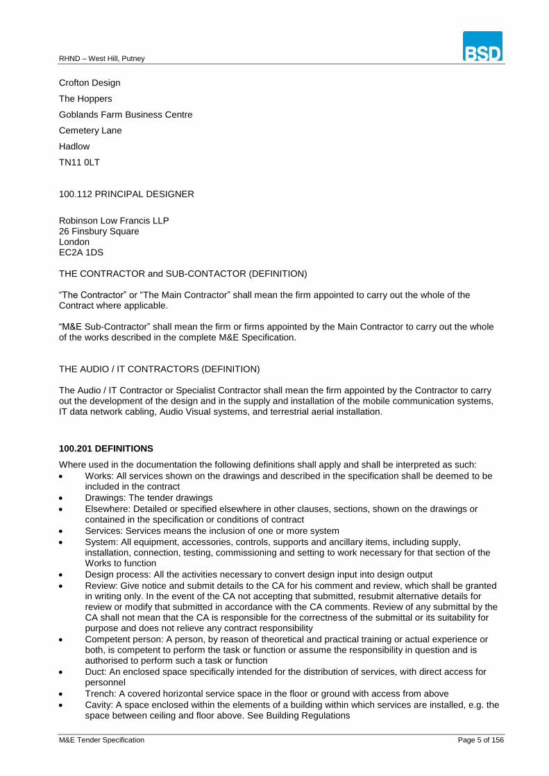
CONTENT
100.000 GENERAL CONTRACT CONDITIONS ........................................................................................... 4
100.101 THE PROJECT ............................................................................................................................... 4
100.401 CONDITIONS OF CONTRACT .................................................................................................... 10
100.511 SUBMITTALS................................................................................................................................ 16
100.531 OBLIGATIONS, DUTIES AND RESPONSIBILITIES .................................................................... 18
100.561 LOCAL AUTHORITY BY-LAWS AND CDM ................................................................................. 24
100.601 THE SITE ...................................................................................................................................... 26
100.701 SCOPE OF BUILDING SERVICES INSTALLATIONS ................................................................. 27
100.722 GENERAL DESIGN CRITERIA .................................................................................................... 28
100.751 BUILDER'S WORK ....................................................................................................................... 30
100.780 TESTING AND COMMISSIONING ............................................................................................... 31
100.801 DRAWINGS .................................................................................................................................. 34
100.850 RECORD DOCUMENTATION ...................................................................................................... 37
100.901 COMPLETION AND HANDOVER ................................................................................................ 40
200.000 FOUL DRAINAGE ABOVE GROUND ........................................................................................... 41
300.000 HOT AND COLD WATER .............................................................................................................. 47
400.000 LOW TEMPERATURE HOT WATER HEATING ........................................................................... 52
500.000 MEDICAL GASES .......................................................................................................................... 63
600.000 VENTILATION................................................................................................................................ 71
700.000 AIR CONDITIONING ..................................................................................................................... 74
800.000 ELECTRICAL INSTALLATIONS .................................................................................................... 81
900.000 ELECTRICAL SERVICES STANDARDS OF MATERIALS & WORKMANSHIP .......................... 94
1000.000 PIPELINES AND ANCILLARIES ............................................................................................... 114
1100.000 DUCTLINES AND ANCILLARIES.............................................................................................. 117
1200.000 THERMAL INSULATION ........................................................................................................... 120
1300.000 TESTING AND COMMISSIONING ............................................................................................ 126
BS APPENDIX ........................................................................................................................................... 127
APPENDIX A - O&M REQUIREMENTS .................................................................................................... 146
APPENDIX B - JEC CEILING VOID WORKS SUMMARY ........................................................................ 149
APPENDIX C – MECHANICAL EQUIPMENT DATA SHEETS ................................................................. 153
APPENDIX D – ELECTRICAL DISTRIBUTION BOARD SCHEDULES ................................................... 154
APPENDIX E – MECHANICAL SERVICES TENDER SUMMARY ........................................................... 155
APPENDIX F – ELECTRICAL SERVICES TENDER SUMMARY ............................................................. 156

RHND – West Hill, Putney
M&E Tender Specification Page 4 of 156
100.000 GENERAL CONTRACT CONDITIONS
100.101 THE PROJECT
This document outlines mechanical, electrical and public health (MEP) services proposed for the refurbishment and extension works to Royal Hospital for Neuro-Disability (RHN) in Putney. Proposed works include refurbishment of a Drapers Ward, ground floor Gym and First Floor (Alexandra’s Wing) Therapy spaces.
The document shall be read in conjunction with the services room data sheets and the Architects and Interior Designers specification and drawings.
The Contractor shall allow for the production of coordinated working drawings and record drawings for all the services.
100.102 THE EMPLOYER:
Royal Hospital for Neuro-Disability (RHN) West Hill, Putney London SW15 3SW
100.104 CONTRACT ADMINISTRATOR:
The term Contract Administrator (CA) is used throughout this specification and his duties will be carried out by the project manager. Robinson Low Francis LLP 26 Finsbury Square London EC2A 1DS 100.106 THE ARCHITECT IBI Group 5th Floor North East Suite Tower Point 44 North Road Brighton BN1 1YR
100.107 QUANTITY SURVEYOR:
Robinson Low Francis LLP 26 Finsbury Square London EC2A 1DS 100.109 BUILDING SERVICES CONSULTING ENGINEER:
Building Services Design
7-17 Jewry Street
London,
EC3N 2EX
100.111 STRUCTURAL ENGINEER:
RHND – West Hill, Putney
M&E Tender Specification Page 5 of 156
Crofton Design
The Hoppers
Goblands Farm Business Centre
Cemetery Lane
Hadlow
TN11 0LT
100.112 PRINCIPAL DESIGNER
Robinson Low Francis LLP 26 Finsbury Square London EC2A 1DS THE CONTRACTOR and SUB-CONTACTOR (DEFINITION) “The Contractor” or “The Main Contractor” shall mean the firm appointed to carry out the whole of the Contract where applicable. “M&E Sub-Contractor” shall mean the firm or firms appointed by the Main Contractor to carry out the whole of the works described in the complete M&E Specification. THE AUDIO / IT CONTRACTORS (DEFINITION) The Audio / IT Contractor or Specialist Contractor shall mean the firm appointed by the Contractor to carry out the development of the design and in the supply and installation of the mobile communication systems, IT data network cabling, Audio Visual systems, and terrestrial aerial installation.
100.201 DEFINITIONS
Where used in the documentation the following definitions shall apply and shall be interpreted as such:
Works: All services shown on the drawings and described in the specification shall be deemed to be included in the contract
Drawings: The tender drawings
Elsewhere: Detailed or specified elsewhere in other clauses, sections, shown on the drawings or contained in the specification or conditions of contract
Services: Services means the inclusion of one or more system
System: All equipment, accessories, controls, supports and ancillary items, including supply, installation, connection, testing, commissioning and setting to work necessary for that section of the Works to function
Design process: All the activities necessary to convert design input into design output
Review: Give notice and submit details to the CA for his comment and review, which shall be granted in writing only. In the event of the CA not accepting that submitted, resubmit alternative details for review or modify that submitted in accordance with the CA comments. Review of any submittal by the CA shall not mean that the CA is responsible for the correctness of the submittal or its suitability for purpose and does not relieve any contract responsibility
Competent person: A person, by reason of theoretical and practical training or actual experience or both, is competent to perform the task or function or assume the responsibility in question and is authorised to perform such a task or function
Duct: An enclosed space specifically intended for the distribution of services, with direct access for personnel
Trench: A covered horizontal service space in the floor or ground with access from above
Cavity: A space enclosed within the elements of a building within which services are installed, e.g. the space between ceiling and floor above. See Building Regulations

RHND – West Hill, Putney
M&E Tender Specification Page 6 of 156
Service Areas: Includes areas within a building with limited finishes such as loading bays, car parks etc
Concealed Services: Includes installations within ducts, trenches or cavities
Exposed Services: Includes installations outdoors or unprotected within service or occupied areas
Terminal Units: Terminal units such as radiators, convectors, fan coil units, induction units, variable or constant volume air boxes and other like equipment
Ancillaries: All specified fittings, accessories, inserts, test points, bracketing, terminal equipment connected to and installed in the engineering services system
CIBSE: The Chartered Institution of Building Services Engineers
BSRIA: The Building Services Research and Information Association
IET: The Institution of Engineering and Technology
IOP: Institute of Plumbing
LPC: Loss Prevention Council
HSE: Health and Safety Executive 100.202 DEFINITIONS OF TECHNICAL TERMS:
The definitions of technical terms associated with the engineering services installations are those included in the latest edition of:
CIBSE - Guides; Commissioning Codes; Technical Memoranda; Building Energy Codes; Lighting Guides; Application Manuals;
IOP - Plumbing Guide
BSRIA - Technical Publications
Loss Prevention Council - EN 12845 - includes current technical bulletins to Mar 04 "Rules for Automatic Sprinkler Installations”
BS 7671 Requirements for Electrical Installations (IEE Wiring Regulations)
British Standards, including Codes of Practice.
Statutory Acts.
100.301 TENDERING PROCEDURES AND REQUIREMENTS
This section outlines the tendering procedures and requirements. 100.302 SCOPE:
These conditions are supplementary to those stated in the invitation to tender and on the Form and Tender and Agreement. 100.303 TENDER DOCUMENTS:
The tender documents consist of the following:
Invitation to tender
Specification for the Works
Set of tender drawings for the Works as detailed in the contract documents
Room data sheets 100.304 PRIVACY OF INFORMATION:
The information contained in the tender documentation shall be treated as private and confidential. 100.305 CHECKING DOCUMENTS:
Check the tender documentation for obvious errors and omissions. Should any such errors or omissions be discovered, inform the office issuing the documents immediately in writing in order that a correction may be issued before the date for submission of the tender. 100.306 TENDER ACKNOWLEDGEMENT:
Acknowledge receipt of the tender documentation and confirm submission of a tender in accordance with the instructions to tender.

RHND – West Hill, Putney
M&E Tender Specification Page 7 of 156
100.307 PERIOD OF VALIDITY:
Tenders must remain open for consideration (unless previously withdrawn) for a period from the date fixed for submission of tenders of not less than 6 months. The date for possession/commencement is to be confirmed. 100.308 TENDER PROCEDURE:
Tendering procedure is in accordance with the principles of industry standards. 100.309 ACCEPTANCE OF INSTRUCTIONS:
The submission of a tender will denote the acceptance of an undertaking to comply with all the clauses contained in the tender documentation unless items of non-compliance are identified as part of the tender submission. 100.310 ACCEPTANCE OF TENDER:
The Employer and his representatives
Offer no guarantee that the lowest, or any tender, will be recommended for acceptance or accepted
Will not be responsible for any cost incurred in the preparation of any tender. 100.311 INSPECTION OF SUPPLEMENTARY DOCUMENTS:
Supplementary documents relating to the contract are available for inspection prior to the submission of the tender. No adjustment shall be made in the tender sum or claim for additional monies or an extension of time allowed due to failure to inspect the above documents and to make due allowance for the information contained therein. 100.312 SITE VISIT:
Before tendering, ascertain the nature of the site, access thereto and all local conditions and restrictions likely to affect the execution of the Contract Works. Inspect any existing installations relevant to the works and study any relevant existing records. No claims will be allowed after submission of a tender for lack of information or other reasons which could have been resolved by such a visit to the site. Arrangements for visiting the site must be made with prior agreement through the office issuing the tender documentation. 100.313 RETURN OF DRAWING AND SPECIFICATIONS:
The complete tender documentation is to be returned to the office of issue when requested should the Tenderer not be successful in their bid. 100.314 ALTERATIONS TO TENDER DOCUMENTS:
No alterations or erasures to the text of any part of the tender documentation shall be permitted. Any tender containing such alterations or erasures may be rejected. 100.315 TENDER ERRORS:
Errors in the priced subcontract specification will be dealt with in accordance with the `Code of Procedure for Single Stage Selective Tendering'. In the event of a Tenderer discovering a genuine error in their tender after it has been deposited, attention in writing may be drawn to the error and an amendment submitted. The amendment may be accepted if deposited on or before the time fixed for receipt of tenders. No adjustment shall be permitted to the sum inserted in the form of tender after the date and time fixed for receipt of tenders. 100.316 UNQUALIFIED TENDERS:
Other than as part of an alternative offer as described elsewhere, no account will be taken of any qualification or special conditions that a Tenderer may impose on their tender. Any tender containing such additional conditions may be rejected.

RHND – West Hill, Putney
M&E Tender Specification Page 8 of 156
100.317 ALTERNATIVES:
Alternative equipment, specialists or methods of carrying out the works in addition to those described in the tender documents may be submitted. Alternative offers shall be indicated on the appropriate document and include:
Details of the alternative equipment, specialist or method proposed
Full technical data for each such alternative, together with details of any consequential amendments to the design and/or other parts of the works
A detailed breakdown of any omissions or additions to the basic tender sum indicated on the appropriate document.
Include for all necessary measures to ensure alternative manufacturer's equipment and the total installation is equivalent to that specified The Tenderer shall include the costs necessary for re-sizing and reselection of associated equipment (including pipework, ductwork and cable sizes) resulting from the proposed alternative together with all resulting design and coordination. Alternative offers will only be considered if accompanied by a compliant tender. 100.318 EXCLUSIONS:
If any part(s) of the Works cannot be tendered as defined in the tender documents, the CA must be informed as soon as possible, defining the relevant part(s) and stating the reasons for the inability to tender. 100.319 INTERPRETATION OF THE TENDER DOCUMENTATION:
Should there be any doubt about the precise meaning of any item for any reason whatsoever, the tenderer must inform the office of issue of the tender documents in writing in order that the correct meaning may be given. Any clarification of the meaning or intent shall be issued in writing only and no other means of communication shall be valid. All Tenderers will be notified of any such explanation. No liability will be admitted, nor claim allowed, in respect of errors in a tender due to mistakes that should have been rectified in the manner described above. 100.320 PROCUREMENT OF MATERIALS:
Allow for the procurement of materials and equipment from suppliers at such a time, and in such a manner as may be necessary to allow for the completion of the Works in accordance with the contract programme. Clearly state in the tender submission any foreseen difficulties with delivery periods for selected equipment or proposed alternatives. No additional costs resulting from non-compliance will be accepted. 100.351 GENERAL:
This section details the particular tender submission requirements. 100.352 RETURN OF TENDER:
The tender documentation is to be returned to the issuing office. The tender documentation is to reach the return address not later than the date advised on the tender letter. 100.353 TENDER SUBMISSION DELIVERABLES:
To be compliant, the tender submission must include the following deliverables as detailed elsewhere:
A tender pricing schedule completed in full
Method statements
Outline programme. 100.354 TENDER STAGE METHOD STATEMENTS:
Method statements must be submitted:
With the Tender.
Provide the following method statements in addition to those stated elsewhere:

RHND – West Hill, Putney
M&E Tender Specification Page 9 of 156
Health and safety statement to include:
Management procedures
Any significant and unavoidable risks that might arise as a result of executing the Works
An outline of the health and safety procedures to be undertaken to safeguard the operatives and of any person who may be affected by the Works
A copy of the company’s health and safety policy document including risk assessment procedures
Accident records for the last five years
Details of any Health and Safety Executive enforcement action
Details of staff responsible for health and safety on this project with details of their qualifications and duties.
Commissioning and testing procedures and management.
Quality control management and procedures.
The method statement must:
Demonstrate compliance with the contract in regard to materials and workmanship
Demonstrate the establishment of standards by means of sample installation and submission of samples prior to installation.
Statement outlining the management team, stating the definition of each person’s role, and the commitment to the project.
Include the curriculum vitae and references for each of the key personnel that will be used on the project
A line management diagram starting at the site supervisors and rising through to management levels.
Details shall be provided for both site and office based teams’ staff.
The Tenderer, at his discretion and at the same time, can submit method statements for other parts of the Works. 100.355 PROGRAMME:
Submit with the tender a programme indicating the sequence and timing of the principal parts of the works including periods for planning, design, procurement, installation and commissioning.
100.371 GENERAL:
This section details particular requirements for the pricing of the tender documentation and cost procedures during the contract. 100.372 BASIS OF CONTRACT:
The contract shall be design and build, based on an all in lump sum based on the performance specification and drawings. 100.373 TENDER PRICING DOCUMENT:
Alterations and qualifications to the specification must not be made without the written consent of the CA. Tenders containing such alterations or qualifications may be rejected. Costs relating to items in the specification that are not priced will be deemed to have been included elsewhere in the tender. The Tenderer shall complete all sections of the tender pricing document in full. Items described in the pricing document are abbreviated for the purpose of the schedule. The Tenderer is to make full allowance for all works associated with the installation of a particular element. Items entered in the pricing document shall be deemed to include all costs involved in carrying out the Works. Where required the Tenderer must identify separately the cost of all items specifically described under preliminaries. Provisional items will be adjusted at the final agreed rates when information is issued in respect of these items. 100.375 SCHEDULE OF RATES:
A schedule of rates must be submitted with the tender.

RHND – West Hill, Putney
M&E Tender Specification Page 10 of 156
The schedule of rates must include rates for all significant items of work. Rates shall include Contractor's cash discount. A quantified schedule of rates accepted by the CA shall only constitute part of the contract in the following respects:
The descriptions of the works and the rates and prices contained therein shall be used for the purpose of adjusting variations
The quantities contained therein shall be used to facilitate the preparation and the checking of interim applications for payment
The provisional and prime cost sums contained therein shall be subject to adjustment in accordance with the rules and procedures contained in the contract conditions.
100.376 ERRORS:
Errors in the priced subcontract specification will be dealt with in accordance with the 'Code of Procedure for Single Stage Selective Tendering'. 100.377 PROVISIONAL SUMS:
Include in the contract price the provisional sums detailed in:
the forms of tender
Any part or the whole of these sums unexpended will be deducted from the final amount due. 100.379 OVERTIME AND ALLOWANCES:
Allow for liaising with the tenants and neighbours to arrange access to carry out works within houses and around them. Include for all necessary overtime and other expenses in the contract price that may be necessary in order to complete the works in compliance with the contract programme. 100.380 SUBMISSION OF FINAL ACCOUNT:
Submit a draft final account to the CA using the contract procedures for checking purposes together with all the necessary supporting documents.
Immediately after the practical completion of the contract Works. Prepare the valuation of variations, omissions and provisional work forming part of the works and where appropriate in accordance with principles defined in this sub-clause. The basis for the determination of such valuation shall be the Quantified Schedule of Rates prepared and submitted at the time of tender and accepted by the CA. All valuations as aforesaid prepared shall be submitted using the contract procedures to the CA for approval. 100.381 INSTRUCTIONS AND VARIATIONS:
All instructions shall be issued in writing and confirmed in a similar manner. Submit the cost of each variation showing the quantities and rates applicable for all materials, etc employed in accordance with the agreed contract schedule of rates. Submit to the CA
Within 10 working days of the receipt of written instructions. No work will be certified for payment until all the necessary information is provided.
100.401 CONDITIONS OF CONTRACT
100.404 INSURANCES:
Under the terms and conditions of the Main Contract the Contractor is required to secure certain policies of insurance, the benefits of which extend to the Sub-Contractor, either partly or in whole. Examine these policies and obtain such supplementary cover as shall be necessary. The successful Tenderer will be required to insure and indemnify the Main Contractor against such obligations in respect of the Sub-Contract as those for which the Main Contractor is liable and must produce insurance policies on demand. 100.421 GENERAL:

RHND – West Hill, Putney
M&E Tender Specification Page 11 of 156
This section details particular conditions and requirements for the project. 100.422 INFORMATION PROVIDED BY OTHERS:
Instructions, drawings, or other information required to be provided by the CA will be provided in due time upon written request provided always that such information is not requested unreasonably distant from nor unreasonably close to the date upon which it is necessary. Provide written request to the CA in good time for any information required. 100.423 PROVIDE EVERYTHING NECESSARY:
Provide everything necessary for the proper execution and completion of the contract works to the true intent and meaning of the contract documents. Details of construction or materials which have not been referred to in the contract documents but the necessity for which may reasonably be implied or inferred from the said documents or which are usually or essential to the completion of the Works, shall be installed with no additional cost. 100.424 SUPPLY OF INFORMATION:
The CA will provide supplementary information from time to time as may be necessary to enable the completion of the Works in accordance with the contract conditions. Allow for such progressive release of further information by the CA during the course of executing the Works. In order to facilitate the orderly and timely production of all further information that shall be considered necessary, submit to the CA for approval a programme indicating the progressive release of such information to enable the completion of the Works in accordance with the contract conditions. 100.425 CO-ORDINATION OF TRADES:
Allow for co-coordinating the contract works with the works of other trades and installations which may be on site during the period of the contract. 100.426 CO-OPERATION WITH OTHERS:
Ensure that the contract works integrates with that of others and that full co-operation is maintained during the execution of the Works with that of others. Co-operate with the Contractor, other subcontractors, suppliers, local authorities and statutory undertakings in the execution of the Works. In the event of any extra costs being caused by failure to programme and arrange the execution of the Works so that it fully integrates with that of others, the installer of the Works may be liable for any additional costs thereby incurred. In particular, the following works carried out by others will require close and careful liaison and co-operation. 100.427 NOTICE OF OPERATIONS:
Work that requires interruption or interference with the operation of any existing services or buildings shall not be commenced without prior written permission of the CA. 100.428 NOISE AND NUISANCE:
Ensure that the contract works are undertaken with as little noise as possible. Ensure no nuisance by noisy working is caused to occupants of premises. Take all necessary precautions to prevent nuisance from smoke, rubbish and other causes. Fit all compressors, percussion tools and vehicles with effective silencers of a type recommended by the manufacturers of the equipment. 100.429 SUPPRESSORS:
Ensure all internal combustion engines used in the execution of the contract works are fitted with efficient suppressors in the ignition system in accordance with the recommendations of British Standards so as to prevent electrical interference to radio or television receiving equipment in the vicinity. All temporary electrical installations, such as motors or the like, shall be prevented from creating such interference and shall be fitted with suppressor equipment in accordance with British Standards and to the satisfaction of the CA. 100.430 PROGRAMME:

RHND – West Hill, Putney
M&E Tender Specification Page 12 of 156
Provide a detailed programme(s) clearly illustrating how the overall programme
Will be achieved within the contract period.
Demonstrate compliance with the Main Contract programme. Allow adequate time for the examination and approval by the CA. Actual activities of production, adjustment, resubmission and review must be identified Provide a separate and detailed commissioning programme for agreement with the CA. Make due allowance for the following.
Commissioning, demonstration and instruction procedures.
Provision of written notice before each (or series of) test, inspection, commissioning or demonstration procedures are to be carried out, not less than
Demonstration to the CA that test instruments and equipment are accurate. 100.431 PROGRESS:
At regular intervals as agreed with the CA provide progress reports during the execution of the contract works in addition to any other similar information required by the contract conditions. The reports shall include:
particulars of materials and equipment on site, or installed
site labour employed
progress of the works
Record progress of the Works weekly on a copy of the programme. Mark up for inspection and record purposes a set of the latest drawings as the works progress. The progress drawings shall be available for inspection by the CA at any time. 100.432 ORDERING SCHEDULE:
Update and modify and submit the ordering schedule on a regular basis as agreed with the CA. Indicate on the schedule any possible problems and when delivery to site has been achieved. 100.433 CONTINUITY OF THE WORKS:
No undertaking is given that the works will necessarily be able to proceed continuously. No claim will be allowed for discontinuity of work due to the necessity to conform to the contract programme. 100.436 ACCESS TO THE SITE:
Access to the site shall be agreed with client prior to work commencement of works on site. 100.437 METHOD AND SEQUENCE OF WORK:
To be decided by the main Contractor and agreed with CA. 100.439 WORKING AREA:
See site address 100.441 USE OR DISPOSAL OF MATERIALS:
Remove from the site any rubbish and debris arising out of the execution of the contract works on a daily basis. Do not discharge any oil, noxious liquids or gases and all water discharged shall be reasonably free from impurities. 100.442 STORAGE:
Weatherproof, safe and secure storage shall be provided for all materials and equipment. All materials and equipment and materials shall be offloaded, stored and transported in accordance with manufacturer's recommendations. All electrical equipment and components shall be kept dry and free from dust. Plug, cap or seal open ends on all ductwork, tubes, conduit, trunking and associated equipment whilst in storage and during transportation to site. Provide racks to prevent distortion of pipes, conduit and similar materials. 100.443 PROTECTION AND PACKAGING:

RHND – West Hill, Putney
M&E Tender Specification Page 13 of 156
All plant, equipment, materials and prefabricated elements of the Works shall be properly packaged and protected against damage during delivery, storage and until fully, finally and properly installed and set to work. Submit to the CA a method statement on protection proposals for both stored and installed plant, equipment and materials. Protection shall also include adverse effects of environmental conditions prevalent in the stored and installed location. Any plant or equipment subject to incorrect storage or inadequate protection will be deemed unacceptable for incorporation into the works and new plant or equipment will be required as a replacement. Damaged plant, equipment and materials or that suffering from deterioration shall be replaced prior to handover. All plant, equipment and materials shall be protected against ingress of water and dust, formation of condensation, extremes and rapid changes of temperature, building works and operations of others. All open ends of pipes, ducts, conduit, and trunking etc shall be capped except when being worked upon. 100.444 CONFIDENTIALITY:
No information related to the contract works shall be given to the press or other media without the written permission of the CA or Employer. 100.445 PHOTOGRAPHS:
Provide progress colour photographs of the contract works. The frequency, location, and photograph size shall be agreed with the CA. All photographs shall be dated and location stated. No unauthorised photographs of the site or the Works or any part thereof shall be taken except with the permission in writing of the CA. Photographs shall not be published or otherwise circulated without the permission of the CA. 100.446 MATERIALS USED:
No acoustic insulation or thermal insulation or sound attenuation materials shall be manufactured with any form of animal hair. All materials supplied shall be a type that will not support bacteria. Deleterious materials shall not be utilised on any part of the Works. Deleterious materials include but not limited to:
Halon/CFC's
asbestos or products containing asbestos
urea formaldehyde or materials which may release formaldehyde
materials comprised in whole or part of man-made and/or naturally occurring mineral fibres which have a diameter of 3 microns or less and a length of 200 microns or less or which contain fibres not sealed or otherwise not stabilised to ensure that fibre migration is prevented
lead where the metal or its corrosion products may be directly ingested, inhaled or absorbed
any other substances generally known to be deleterious at the time of installation All jointing materials shall be of a type approved by the respective authority. Warrant that deleterious materials are not incorporated in the Works. 100.447 ADVERTISING:
No form of advertising will be allowed on any part of the site or the Works without written CA approval. 100.448 PATENT RIGHTS:
Indemnify against all claims, costs or expenses in connection with any patented, copy righted or protected articles supplied and used on or in connection with the Works. Any payments or royalties payable in one sum or by instalments shall be included in the contract price and paid to whom so ever they may become due. In the event of any claim being made in connection with such patented or protected articles, conduct any negotiations or litigation in connection with such claim at own expense. 100.449 BENEFICIAL USE OF INSTALLATIONS:
Systems shall not be used before practical completion without prior approval of the CA. Systems used before practical completion not for the benefit of the Employer must have all defective consumable elements replaced by new including:

RHND – West Hill, Putney
M&E Tender Specification Page 14 of 156
lamps and tubes
filters Replacement of consumable elements shall be not more than days prior to practical completion. If instructed by the CA operates the installations or any part of them prior to practical completion, provided that such operation is practicable and does not prejudice the responsibilities and obligations under the contract. All costs arising from the use of such installations will be reimbursed at rates or where no such rates are applicable at reasonable rates agreed with the CA before commencing operation of the installations. 100.450 DEFECTS LIABILITY:
Liability for making good defects in the Works shall be for a period of months from the date of issue of the certificate of practical completion for the installations. If it is necessary to replace or renew any portion of the contract works as part of liability for defects, the defects liability period in respect of that portion of the contract Works shall be deemed to commence from the date of such replacement or renewal. The CA may require that new tests be carried out to demonstrate that the plant is continuing to work satisfactorily if the replacement or renewal may affect the efficiency of the Works or any portions thereof. In the remedying of defects in the contract Works take all necessary precautions to minimise the risk of damage to the buildings, the decorations, the fittings and the equipment. In the event of such damage occurring bear the cost of replacement or making good, subject to the proviso of being granted the benefit of any settlement in respect of such damage accepted by the insurers under the insurance policies taken out in accordance with the requirements of the contract. Agree with the CA a programme for the carrying out and the completion of any work not finally finished at the time of the contract Works being offered for acceptance and which does not prejudice the issue of a practical completion certificate. This work may be requested to be executed out of normal hours and no additional costs will be accepted for this action. Prior to practical completion submit a method statement for the approval of the CA outlining how the defects which arise during the defects liability period will be rectified to ensure that disruption to the use of the building is kept to a practical minimum. No additional costs will be accepted for undertaking works executed out of normal hours. 100.451 RIGHT OF ACCESS DURING DEFECTS LIABILITY PERIOD:
Right of access will not be unreasonably withheld, at all reasonable working hours and at own risk and expense, to any part of the contract works for the purpose of inspecting the working of the installations or to the records of the working and the performance thereof. Subject to CA approval, that shall not be unreasonably withheld, undertake any tests considered necessary at own risk and expense. During the defects liability period and all necessary remedial works and/or rectification of defective materials and equipment liaise closely with the Employer's staff. All such work shall be carried out in such a manner as to avoid or minimise shut-down time and inconvenience to the Employer. 100.452 RATIONALISATION OF COMPONENTS:
Similar items of apparatus and equipment shall be made and provided by the same manufacturer where practicable and corresponding parts of all apparatus and equipment shall be interchangeable to reduce the need for different attention and spares. 100.453 SUPPLY OF COMPUTER HARDWARE AND SOFTWARE:
Obtain on behalf of the end user all appropriate licences, permissions, copyright waivers, rights of use and the like from the owners of the software rights. Ensure that the end user is properly registered with the software supplier for support and appropriate updating. Ensure that application software is written in compliance with BS 7649. 100.454 FIRE PRECAUTIONS:
Take all reasonable fire precautions in respect of stores, workshops and other installations. Where it is necessary to use any naked flame or welding equipment in executing the contract works and where combustible materials are in use, adequate protection shall be given to other adjacent materials and personnel. Suitable fire extinguishers shall be readily available at the position where such work is proceeding.

RHND – West Hill, Putney
M&E Tender Specification Page 15 of 156
100.455 INTERFERENCE WITH TRAFFIC:
Maximum facilities for access and transit shall be provided in all works that may interfere with the traffic on the roads, paths and footways. Should any part of the Works be executed in such a way as to cause unnecessary obstruction to traffic with neglect to remove or remedy the same forthwith when called upon to do so, then any obstruction shall be removed and the costs recovered. 100.456 DAMAGE TO STRUCTURE:
Exercise due care and attention in carrying out the contract works and be fully responsible for any damage caused to the structure or building finishes. Obtain permission from the CA before any holes are cut in floors, walls or steelwork, etc. 100.457 METHOD STATEMENTS:
Submit method statements to the CA prior to commencement of the contract works for the following work activities:
Each item of work. 100.458 INSPECTION BEFORE CONCEALMENT:
Whenever work requiring inspection or testing is subsequently to be concealed give the following the notice to the CA so that inspections may be made or tests witnessed before concealment 100.459 EQUIPMENT GUARANTEES:
Plant and equipment guarantees shall commence at the date of practical completion and run for a minimum of 12 months after this date. Any costs associated with this requirement shall be included in the contract price. 100.460 SITE MODIFICATIONS:
Site modifications to assemblies shall not be made without written approval of the CA. Where site modifications to assemblies are authorised undertake in accordance with manufacturer's certified drawings and instructions. Ensure that all modifications undertaken comply with the relevant standards and all test certification obtained. 100.461 DIMENSIONS:
Where installations are dependent upon site dimensions ensure that these are available before proceeding with the Works. Dimensions should not be scaled from drawings. Where dimensions are indicated on drawings check these on site, as appropriate, to ensure building construction tolerances and manufacturing tolerances can be accommodated. Equipment should not be ordered or manufactured using dimensions indicated on the Tender drawings. 100.481 QUALITY CONTROL:
Prepare and submit to the CA a method statement to indicate fully the quality control programme for the contract works Time scale
Within 2 weeks of contract appointment 100.482 WORKMANSHIP AND MATERIALS:
All materials, articles and workmanship shall be of the best quality and execution as detailed in the specification and drawings. All equipment and materials to be installed shall be new unless otherwise indicated. All equipment shall be installed in accordance with the manufacturer's written instructions and recommendations. All materials considered by the CA to be unsound or not in accordance with the specification shall immediately be removed and properly replaced to the satisfaction of the CA at no additional cost. All work carried out imperfectly or with faulty materials must be immediately removed and properly replaced to the
RHND – West Hill, Putney
M&E Tender Specification Page 16 of 156
satisfaction of the CA at no additional cost. The manufactured articles specified shall serve as a quality standard. Where manufactured items are not specified by name submit with the tender all necessary details of proposed articles. The CA shall approve these articles before their use is permitted. 100.483 DEFECTS:
Agree with the CA a system of recording defects that should include
A reference to identify the defect
Description of the defect
Remedial works proposed
Agreement to remedial works proposed
Confirmation of defect clearance 100.501 SITE STAFF:
Employ a competent full-time site based project manager/engineer and supporting team dedicated full time to the project and not involved in the installation of the Works who shall have full authority to act in connection with the contract works. Staff of sufficient number and competence in the opinion of the CA, shall be provided as necessary for design, drawing and technical information production, programming and administration to ensure efficient and satisfactory execution of the contract works. Provide all necessary superintendence during the execution of the contract works. The said staff shall be in attendance on site during the whole time that work is in progress. Employ on the site suitable qualified engineering staff to be in charge of the contract works from commencement to completion. The said staff shall be in attendance on site during the whole time that work is in progress. Responsibility for all drawings and technical information production shall be undertaken by a nominated engineer Curriculum Vitae shall be submitted with the tender for all key staff. Any change made to the appointment of staff during the contract works shall be agreed with the CA with maximum notice being provided. If the CA is of the opinion that any member of the site staff has been guilty of a serious breach of his duties, he may by notice require that person to be replaced within 1 weeks of the notification.
100.511 SUBMITTALS
This section outlines the requirements and procedures for submittals to the CA. 100.512 SUBMITTALS:
Prior to any orders being placed the CA shall review all drawings and manufacturer's details. Submittals shall be in a clear, definable and easily read format with the specified technical details, notes, performance data and calculations where applicable all in the English language. Where drawings are to be examined the manufacturer's details shown on the drawings must have been previously approved. Include all costs for attending meetings associated with the submittal review procedure. Agree with the CA where samples of materials offered for review are to be sent. Issue progressively drawings, calculations and submittals as agreed in advance with the CA for review. All correspondence related to the examination and review procedure shall be directed through CA and copied to services engineer. The timescale for review or comment or otherwise on all submittals shall be 5 working days from receiving submittal by services consultant. 100.513 SCHEDULE OF DRAWINGS AND SUBMITTALS:
Provide a schedule of all proposed drawings and submittals required for comment. Indicate as a minimum the following information on the schedule:
Drawing number and revision number
Drawing title and service
Scale
Date required for final comment

RHND – West Hill, Putney
M&E Tender Specification Page 17 of 156
Date of commencement of drawing production The schedule shall be updated as necessary on a regular basis at intervals agreed with the CA during the contract period. The programme for production of drawings and other submittals should include the necessary time for:
Submission
Examination
Alterations and re-submission in the event of the initial submission not being accepted
Final issue Allow adequate time in the programme in order not to cause delays. The full extent of all submittals shall be indicated in the schedule. Group submittals for a particular part of the building or building engineering service as agreed with the CA. 100.515 EQUIPMENT PERFORMANCE DETAILS:
Details of the equipment selected for inclusion into the Works shall include the following information:
Plant item description, reference identification and serial number.
Electrical input rating - kVA, Volts, Phase.
Operating mode - duty, standby, generator etc.
Starting characteristics - starter type, current, starts/hour and starting time.
Performance characteristics - (full load current and power factor).
Noise level.
Weight. The format of the information shall be as agreed with the CA. 100.516 PREPARATION OF DRAWINGS:
Agree with the CA a document numbering system prior to preparing any documents. All drawings shall be prepared using a computer aided draughting system and the software used to produce drawings shall be approved prior to commencement of drawing production. Each service shall be represented by a separate layer/overlay, for subsequent easy modification. Prior to commencement of drawing production agree the sequence of layers, pen colours and sizes. The medium for transfer of information shall be pdf and AutoCAD dwg. Drawing plots shall be "A" size to British Standard, with an agreed logo/title block. The standard drawing size is to be A1. Scales used on drawings shall be selected to convey clearly the proposals 100.517 REVIEW OF SUBMITTALS:
Submittals will be examined for compliance in principle with the design intent. Such examination shall not relieve any responsibilities and obligations under the contract. Examination of any submittal by the CA shall not mean that the CA is responsible for the correctness of the drawing or submittal or its suitability for purpose. These responsibilities shall remain as defined elsewhere and as the contract. Allow adequate time in the programme for submittals with due allowance for incorporation of comments and resubmission in order not to cause delays. Each package shall contain all drawings, support information, manufacturer's literature, etc. necessary to facilitate examination by the CA. Revised items on drawings shall be clearly indicated and annotated with a revision number/letter. Submittals will be returned indicating "A", "B" or "C" action: "A" - no comments, proceed with works "B" - subject to comments, works may proceed, "C" - subject to major amendments, works cannot proceed until resolved. Drawings and submittals with "B" or "C" action shall be adjusted / revised for comments immediately and re-submitted to the CA within 10 working days or earlier if site progress dictates. Where drawings are revised and updated during the construction stage these shall be issued to the CA for examination of the revision only, the revision being clearly marked. Builder's work information and installation drawings shall not be examined in detail but shall be examined by the CA for general suitability. Record drawings are to be prepared as the contract works progress and shall be examined in the same manner as for other submittals. The timescale for review or comment or otherwise of record drawings shall be 5 working days.
RHND – West Hill, Putney
M&E Tender Specification Page 18 of 156
100.518 MISTAKES IN SUBMITTALS:
Examination and/or issue on a CA instruction of submittals shall not be deemed to remove any duties, obligations and responsibilities under the contract. Be responsible for any error, discrepancy or omission in any submittal, presentation or drawing prepared or where others have prepared these for submittal. The said indemnity shall be subject to the proviso that such error, discrepancy or omission is not due to any inaccurate data, drawing or information provided by the employer or by the CA on his behalf. 100.519 SAMPLES:
Provide free of charge samples of material and workmanship proposed to be used in the Works. Samples shall include all alternative finishes available if required. Approval of the CA shall be obtained before equipment is placed on order 100.520 FORM AND NUMBER OF SUBMITTALS TO BE PROVIDED:
All submittals shall be issued to the CA and services consultant Provide drawn information in the following forms:
Co-ordination drawings
Initial copies for comment
Final copies for design team
Installation drawings
Initial copies for comment
Final copies for design team
Installation wiring drawings
Initial copies for comment
Final copies for design team
Manufacturer's drawings
Initial copies for comment
Final copies for design team
Builder's work information
Initial copies for comment
Final copies for design team
Controls logic diagrams
Initial copies for comment
Final copies for design team
Switchgear, starter and control instrumentation panel drawings
Initial copies for comment
Final copies for design team
As-installed drawings
Site record copy in print form 100.521 REVISIONS TO DRAWINGS:
Where revisions take place either under the authority of a CA instruction, or by written agreement with the CA or when revised architectural, structural or services information is issued, all drawings shall be modified accordingly and shall be re-issued for construction purposes subject to examination by the CA. The issue of revised drawings shall be in accordance with and with regard to the agreed programme for construction and where time is available re-issues shall be grouped together, as agreed with the CA.
100.531 OBLIGATIONS, DUTIES AND RESPONSIBILITIES
This section details the specific obligations, duties and responsibilities undertaken as part of the contract works. 100.532 OBLIGATIONS:
Undertake responsibility for all works defined in the work sections and shown on the drawings, and in particular the following:

RHND – West Hill, Putney
M&E Tender Specification Page 19 of 156
Undertake the development of design into working drawings.
Undertake the responsibility for resolving final spatial co-ordination.
Undertake specific detailed design tasks as indicated elsewhere in the specification.
Prepare construction programmes for the Works as stated elsewhere and for design activities.
Co-ordination of the engineering services, with each other and with the building structure and fabric.
Undertake all on-site co-ordination with all other trades, disciplines, manufacturers and suppliers.
Undertake the role of lead co-ordinator and agree principles of co-ordination with all parties concerned.
Check the provisions for, and adequacy of builder's work information previously issued prior to the award of the contract
Fully re-evaluate and take full responsibility for all parts of the design and building elements that may be affected by acceptance of alternative plant selections
Undertake the role of lead co-ordinator and agree principles of co-ordination with all parties concerned. Incorporate details provided by others into the installation information Provide the following drawings as defined elsewhere:
Detailed design
Co-ordination
Installation
Installation wiring drawings
Provide builders work details based on the installation, manufacturing and shop drawings. Prepare such reports, calculations and details as required for submission to any appropriate authority including the coordination of such information by suppliers, specialists, etc needed to be included in any submission. Fully re-evaluate and take full responsibility for all parts of the design and building elements that may be affected by acceptance of alternative plant selections Undertake all on-site co-ordination with all other trades, disciplines, manufacturers and suppliers Provide suitable clearance on completion. Supply, deliver to site, unload, store, protect and co-ordinate movement of all plant, equipment and materials required for the works including lifting and hoisting. Fix and install correctly all plant, equipment and materials and ensuring that all associated works are correctly executed. Undertake the fire stopping of all holes associated with the works. Install fire barriers where a fire rated partition is penetrated. Inspect all plant, equipment and materials as delivered or where specified at the manufacturer's works Preparation of the operating and maintenance manuals, planned maintenance schedules. Appoint a specialist responsible for the preparation of the operating instructions and maintenance manual Undertake the testing and commissioning of the works. Appoint a commissioning specialist responsible for the testing and commissioning of the works. Provide a commissioning report in accordance with Building Regulations. Remove the following existing installations:
Existing services that are not been re-used.
Maintain the existing services during the duration of the Works including the provision of any additional work and materials necessary. Survey the existing services installation prior to any work been carried out to ensure it does not affect any areas not been worked on at that time and advise the CA if there are any problems.
Incorporate the survey data into the installation information.
Produce record drawings for the complete existing services prior to commencement of works. 100.533 DESIGN RESPONSIBILITIES:
Development of the design responsibilities shall include the activities listed below, in addition to those

RHND – West Hill, Putney
M&E Tender Specification Page 20 of 156
activities normally undertaken through the custom and practice of the industry. Responsibility of the suitability and correctness of the design or other obligations as defined in the contract documentation will not be affected by comments of the CA. The design responsibilities shall include:
Check the provisions for, and adequacy of the preliminary builder's work drawings or information previously issued by others prior to the award of the contract
Detail all access requirements including access to false ceilings and ducts for maintenance. Provide fully dimensioned and annotated drawings.
Location of drain and vent points and pipework gradients.
Detailed design and locations of brackets and supports.
Submit details of all types of brackets and supports including fixing details prior to installation.
Submit load calculations prior to installation.
Detailed design and location of expansion anchors and guide locations.
Submit details of all expansion anchors and guides, including fixing details, load and thrust calculations for comment prior to installation.
Final valve and damper locations.
Calculating all final fan system resistances based on the final equipment selection and co-ordinated installation drawings.
Calculating system water capacities and quantities of chemical additives
Final selection of all anti-vibration mountings to suit the particular application of the mounts.
Check the sizing and protection of any circuits that are been modified prior to any work commencing.
Preparing detailed electrical wiring diagrams of all equipment supplied showing all interconnections between equipment to enable all necessary wiring to be undertaken.
Detailed design of automatic controls systems insofar as it is required to meet with operational and spatial requirements of the specification. The installer shall be responsible for ensuring the full compatibility of the plant and equipment with the specified function and for the design and incorporation of all interfaces (including relays or other devices or modifications to hardware or software)
Dimensioning of, and final installation details of, automatic control panels to suit the detailed requirement of the agreed supplier of the controls equipment. The installer shall be responsible for ensuring that:
Control panel cable entry/exits are possible in the final location.
Safe operating and maintenance clearances are provided.
Final locations of:
Test points
Control sensors
Detectors
Thermostats
Gauges
Sizing of cable terminations for all items of equipment.
Appropriate for the rating of fuses installed in plug tops for the rating of the connected equipment. Dimensioning of and final installation details of electrical switchgear including:
Provision of adequate safe operating and maintenance clearances. Earthing and bonding requirements for:
mechanical engineering services
electrical engineering services
Ensuring cable size selections as specified are not invalidated by the selection of alternative routes during installation or selection of alternative manufacturer's
Final detailed design of fire alarm system component and cabling requirements to meet with the particular manufacturer and the engineering specification requirements.
Final detail design of Fire Protection services
Detailed design, supply and installation of duct platforms access covers, gratings, and ladders. MECHANICAL SERVICES
Development of the design into working drawings for all mechanical services
Design and final location of drain and vent points and pipework gradients.
Design of adequate provision for movement of services and systems due to thermal expansion and

RHND – West Hill, Putney
M&E Tender Specification Page 21 of 156
contraction, hydraulic pressures and building movement.
Include cold draw calculations.
Proving of expansion loops in lieu of expansion equipment. Detailed design and location of expansion anchors and guide locations including:
Fixing details.
Load and thrust calculations.
Calculate all final pump system resistances based on the final equipment selection and co-ordinated working and installation drawings.
Calculate all final fan system resistances based on the final equipment selection and co-ordinated working and installation drawings
Detailed design and sizing of refrigerant pipework between items of equipment provided as part of the Works based on the final equipment selection and co-ordinated working and installation drawings.
Calculate system water capacities and quantities of chemical additives based on the final equipment selection and co-ordinated working and installation drawings.
Design and install all necessary temporary facilities for flushing, commissioning, etc
Undertake the final sizing, selection and determination of final locations of commissioning sets including any proportioning of mains losses, etc based on the final equipment selection and co-ordinated working and installation drawings.
Final selection of system(s) pressurisation units and expansion vessels based on the final equipment selection and co-ordinated installation drawings.
Final sizing of sections of ductwork between terminal units and diffusers to ensure the specified acoustic criteria and duct velocities.
Final selection and location of control dampers, control valves, etc to achieve the specified function and to suit the characteristics of items served and final system configurations based on the final equipment selection, co-ordinated working and installation drawings. To include required access requirements.
Final design of flues to include the incorporation of the requirements of the respective manufacture, building control, environmental health officer and current legislation eg Clean Air Act.
Determining the extent and design of trace heating systems for frost protection of relevant services and temperature maintenance on domestic hot water systems.
Detail design of:
Fire rated ductwork systems.
Ductwork fire protection systems.
Obtain all necessary statutory approvals.
Final detailing and confirmation of the location and sizes of duct connections to external louvres.
Design and selection of sound attenuation equipment to satisfy the particular performance requirements of the specification and the spatial allowances based on final equipment selection and final co-ordinated working and installation drawings.
Design of final acoustic requirements or modification of equipment to attain the particular performance requirements of the specification.
Final selection of all anti-vibration mountings to suit the particular application of the mounts.
Undertake the redesign of the final acoustic requirements associated with approved alternative equipment or materials which subsequently varies the Works in any way whatsoever.
Provide a report confirming that the results of the leakage tests are in compliance with the specified ductwork leakage requirements.
ELECTRICAL SERVICES:
Development of the design into working drawings for all electrical services
Selection of fuse sizes installed in plug tops and fused connection units, appropriate for the rating of the connected equipment.
Design of cable or cable containment terminations on to electrical equipment.
Dimensioning and final installation details of electrical switchgear including.
Provision of safe operating and maintenance clearances.
Acceptable cable entries for the final location.
Detailed design of earthing and bonding requirements for:
Electrical engineering services.

RHND – West Hill, Putney
M&E Tender Specification Page 22 of 156
Mechanical engineering services.
Architectural elements.
Structural elements.
Design of fixing, connections and bonding details as required for final installation of lightning protection systems.
Check that cable size selections as specified are not invalidated by the selection of alternative routes during installation or selection of alternative manufacturers.
Detailed sizing, location, routes and design of electrical containment systems
Trunking.
Tray.
Supporting structures, brackets, fixings etc.
Design of electrical conduit systems including capacity, location, routes and fixing.
Verify cable sizes, voltage drops, discrimination and fault handling of cables based on the installation drawings, selected equipment and actual installed cable lengths.
Final detailed design of the fire alarm system including component and cabling requirements to meet with particular manufacturer's recommendations, the engineering specification and requirements of statutory bodies, standards and codes.
PUBLIC HEALTH SERVICES
Development of the design into working drawings for all public health services
Modify distribution systems and equipment capacities as may be required as a result of final detailed spatial co-ordination.
Detail Design of Fire Protection Services AUTOMATIC CONTROLS
Detailed design of automatic controls systems insofar as it is required to meet with the operational, functional and spatial requirements of the performance specification.
Check the full compatibility of the plant and equipment with the controls system and specified function.
Prepare: Wiring schematics.
Control panel labelling details.
Equipment schedules for the complete Works.
Design and incorporation of all interfaces (including relays or other devices or modifications to hardware and/or software).
Undertake the dimensioning and final installation details of automatic control panels to suit the detailed requirements of the agreed supplier of the controls equipment including provision of safe operating and maintenance clearances and ensuring acceptable cable entries/exits in the final location.
Final locations of:
Test points.
Control sensors.
Detectors.
Thermostats.
Sizing of cable terminations on all items of equipment.
Prepare detailed electrical wiring diagrams of all equipment supplied showing all interconnections between equipment to enable all necessary wiring to be undertaken.
Detailed sizing, capacity, location, routes and design of electrical containment systems including supporting structures, brackets, fixings etc associated with the automatic controls and BMS
Conduit.
Trunking.
Tray.
Verify all cable sizes, voltage drops, discrimination and fault handling of cables based on the installation drawings, selected plant/equipment and actual installed cable lengths.
Ensure that software engineering and programming is completed and undertaken so that systems function in the prescribed manner.

RHND – West Hill, Putney
M&E Tender Specification Page 23 of 156
BUILDERS WORK:
Provide all builders work details based on the detailed design, working drawings and manufacturer's drawings to facilitate the installation of the works. Provide fully dimensioned drawings showing both size and position of builder's work making due reference to the structural engineering and architectural final dimensioned detailed drawings.
Detail all access requirements including access to false ceilings and ducts for maintenance.
Provide fully dimensioned and annotated drawings.
Undertake the redesign of the associated builder's work for approved alternative equipment or materials which subsequently varies the works in any way whatsoever.
Detailed design and locations of brackets and supports.
Submit details of all types of brackets and supports including fixing details.
Submit load and thrust calculations.
Design, supply and installation of support for plant and services.
Steelwork.
Brackets.
Hangers and clips etc.
Plinths.
Inertia bases.
Detail and supply sleeves, inserts, frames, fixing anchors etc., and any other items required to be cast or built into the structures by others, including coordination of positions to such extent and accuracy to allow structural construction to proceed.
Detail design, supply, installation and co-ordination of all access platforms, access covers, gratings, ladders, stairs, rails and protecting elements required for future maintenance and operation of plant/equipment.
Provide fully dimensioned and annotated drawings.
Undertake and detail all fire stopping and sleeving systems for the Works where they pass through fire compartments.
Detail and install fire barriers where a fire rated partition is penetrated.
Undertake and detail the weatherproofing of all services passing through external elements of the building.
Undertake and detail all acoustic stopping associated with the Works.
Detail the final requirements for access to ceiling voids and builder's work ducts for maintenance and operation.
100.534 ALTERNATIVE EQUIPMENT:
Where the CA has accepted proposed alternative equipment or materials prior to the award of the contract and which subsequently varies the main works and/or the Works in any way whatsoever, then:
Be responsible for meeting all the additional costs and technical requirements arising from such a change
No claim for additional costs or delay to the completion of the works will be allowed.
Undertake the redesign of all engineering services and builder's work affected by these equipment changes at no additional cost or extension or delay to the programme.
Should any alternative item proposed not carry appropriate certification, ensure independent testing is carried out to confirm compliance at no additional cost. 100.535 CO-ORDINATION OF SERVICES:
All aspects of the works require detailed co-ordination to avoid any possible clash or conflict with other trades and disciplines. Undertake such co-ordination in relation to the works. No extra cost or claim will be allowed due to conflict of works or installations, where full liaison with other trades and disciplines would have prevented such an occurrence. When any new, revised or updated architectural, structural or services information is issued by the CA under the authority of an instruction, examine such information and if necessary modify the works accordingly to prevent any clashes or abortive work due to such instruction. No extra cost or claim will be allowed to cover any clashes or abortive work that result from not requesting an explanation or seeking clarification in respect of any such revision. No extra cost or claim will be allowed due to conflict of works or installations, where full liaison with other trades and disciplines would have prevented such an occurrence.

RHND – West Hill, Putney
M&E Tender Specification Page 24 of 156
100.536 CO-ORDINATION OF SERVICES ON SITE:
Allow for co-ordinating the contract works with the works of other trades and installations which may be on site during the period of the contract either during or prior to their incorporation into the works. Where minor clashes of services occur on site that were not foreseeable at the design or co-ordination drawing stage then these clashes or minor co-ordination matters shall be resolved by discussion and agreement with other trades and disciplines. The CA shall be informed of the action to be taken by an approved means. No instructions will be issued to cover such minor clashes. 100.537 SURVEYS:
Ascertain the nature of the site and all local conditions and restrictions likely to affect the execution of the Works. Before commencing work, carry out a survey and examination of buildings, structure and engineering services affected by the works. Examine all available drawings of the engineering services and report any discrepancies to the CA. 100.538 SITE DIMENSIONS AND LEVELS:
Install all engineering services using a laser levelling system wherever possible and co-ordinate the measurements with all other trades and disciplines to prevent any clashes. Obtain all dimensions and levels on site for the actual setting out of the works. As the development advances measure on site all works by others that may foreseeably affect the works. These dimensions shall be incorporated into the installation drawings or marked up on revised drawings if already issued. No extra cost or claim will be allowed for any errors arising from inaccurate setting out or failure to check actual site dimensions. Reimbursement will be sought for any abortive expenditure. 100.539 MAINTAINABILITY:
Demonstrate that all plant and equipment incorporated into the Works can be safely and easily maintained in full compliance with:
Health and Safety legislation.
CDM requirements.
British Standards.
Health Technical Memoranda. Ensure that adequate space is provided for future replacement of plant or parts and that all access panels/doors are unobstructed. 100.540 TERMINAL UNIT LOCATIONS:
The positions of all connection points, accessories, apparatus, equipment and other room terminals shown on the tender drawings are approximate and for guidance in the preparation of the tender. Agree, with the CA, which terminals are subject to final positioning on site. Confirm mounting heights with the CA before commencing work on site. 100.541 CO-OPERATE:
Co-operate with the contractor, other subcontractors, suppliers, local authorities and statutory undertakings in the execution of their work. In particular, the following works carried out by others will require close and careful liaison and co-operation.
100.561 LOCAL AUTHORITY BY-LAWS AND CDM
This section details the requirements for compliance with Local Authority By-laws and CDM. 100.563 AUTHORITY NOTICES:
Documents requiring the Employer's signature shall be forwarded to the CA in time to meet the contract works programme in order for the necessary test and supply arrangements to be made. No additional costs or extension to programme shall be allowed due to reconnections, revisits etc by supply authorities or failure to programme the works.

RHND – West Hill, Putney
M&E Tender Specification Page 25 of 156
100.564 BYE-LAWS, NOTICES, ETC:
Observe and comply with the requirements of all Statutes and Bye-Laws. Serve notices on the Authorities having control of the road surfaces before the same are broken up and likewise serve notices on the owners of sewers, drains, water, gas or other mains, electric cables, tramways and other services which may in any way be affected by the execution of the Works. Inform all necessary parties when work necessitates such notices to be given. 100.581 HEALTH AND SAFETY GENERAL:
Conform to all safety rules, regulations and codes of practice. Check that facilities provided by others fulfill the obligations and advise accordingly. Provide all necessary first aid facilities. Appoint a "competent person" on the site to manage health and safety during construction. Ensure, so far as is reasonably practicable, that all persons employed on, or visiting, the site are adequately informed, instructed, trained, supervised and equipped such that they are able to carry out their duties safely. Ensure that safety helmets and other necessary protective clothing are available to site visitors. All safety helmets and protective clothing must comply with the latest British Standards. Ensure that only authorised persons are allowed into any construction area. Ascertain the accuracy and sufficiency of information provided by the Employer or the CA to ensure the safety of all persons and the Works. Wherever possible labour saving lifting devices shall be used and materials sized to allow easy manual lifting. 100.582 CDM REGULATIONS:
The management of health and safety is to be undertaken in conformity with the requirements of the Construction (Design and Management) Regulations and the corresponding Approved Code of Practice. Comply with the requirements of the CDM Regulations by
Compiling risk assessments
Preparing method statements
Providing information on the contract works that might affect the health and safety of any person
Providing all necessary input to the Construction Phase Plan
Providing all necessary input to the health and safety file Supply any method statements and comply with all CDM procedures required by the CDM Co-ordinator and the Principal Contractor. 100.583 PRE-CONSTRUCTION INFORMATION AND CONSTRUCTION PHASE PLAN:
Pre-Construction Information is included as part of the tender documents. The Pre-Construction Information provides information required by the CDM Regulations and highlights significant risks to health and safety identified during the design stage. Produce the Construction Phase Plan in accordance with the requirements of the CDM Regulations prior to the commencement of works on site The Construction Phase Plan shall not be limited to those particular risks identified in the tender stage health and safety plan but shall include consideration of all reasonably foreseeable risks The Construction Phase Plan must be adequately developed, as far as is reasonably practicable allowing for any phasing of works, etc., in sufficient time to allow it to be submitted for approval prior to the commencement of any works on site. In the case of phased works the health and safety plan relating to the work content of any phase must be adequately developed and submitted for approval prior to the commencement of any work within that phase of the project. Where design activities are undertaken or there is involvement in the design of any elements of the contract works co-operate with and provide information to the CDM co-ordinator in accordance with the designer's duties under the CDM regulations. Ensure that all sub-contractors are issued with copies of the Construction Phase Plan prior to the submission of their tenders and that they price for compliance. Ensure that all sub-contractors complete appropriate assessments of the risks to health and safety in respect of their works as required under applicable statutory legislation, including the latest Management of Health and Safety at Work Regulations and the Control of Substances Hazardous to Health Regulations. The Construction Phase Plan shall be reviewed and revised as necessary in line with any information

RHND – West Hill, Putney
M&E Tender Specification Page 26 of 156
received or any changes in the requirements of the contract works. Any changes shall be promptly advised to all relevant parties. Ensure, so far as is reasonably practicable, that all sub-contractors, employees and self employed persons who are at work on the construction of the project conform with the requirements of the Construction Phase Plan. 100.584 COSHH REGULATIONS:
Comply with the latest edition of the Control of Substances Hazardous to Health Regulations. Provide with the tender an assessment of the risks in undertaking the contract works Provide with the tender a method statement on the steps proposed to meet the requirements of the Regulations Undertake COSHH assessments for all activities and substances provided or used on site to assess their potential health hazards. Copies of all relevant COSHH assessments must be issued to the operatives concerned and strictly monitored. Particular attention must be given to the use of glues and sealant. Where the use of substances falling within the scope of the Regulations forms part of the contract works notify the CA in writing, together with the additional costs, if any, of use of non-hazardous alternative. Ensure during the course of the contract works, and under all circumstances, that all substances falling within the scope of the Regulations are positively so identified at all times and that they are transported, handled, stored, used and disposed of in strict accordance with their manufacturer's/supplier's recommendations. Where use of substances falling within the scope of the Regulations is required for the operation and maintenance of the completed contract works, ensure that
Suitable facilities are available for the onsite storage of such substances and that all necessary warning/instruction notices are provided at the point of their storage and use
Provision of any special protective clothing, eye protection and similar safety equipment for the operation and maintenance of the Works and in sufficient quantity for
1 year operation
Employer's staff has been fully trained in the use, handling, storage, transport and disposal of the substances concerned prior to handover.
The type, use and control of the substances have been fully and correctly identified in the operating and maintenance manuals/health and safety file. 100.585 ASBESTOS:
No material or goods containing asbestos shall be incorporated in the contract works. Be responsible for certifying at practical completion of any section of the contract works that no asbestos or asbestos related materials have been incorporated or by any sub-contractor employed. 100.586 RISKS TO HEALTH AND SAFETY:
Submit a statement with the tender describing any significant and unavoidable risks which may arise as a result of carrying out the contract works and the measures proposed to safeguard the health and safety of operatives and of any person who may be affected by the contract works.
100.601 THE SITE
This section outlines information on the site. 100.602 SITE LOCATION:
Royal Hospital for Neuro-Disability (RHN) West Hill, Putney London SW15 3SW 100.603 DESCRIPTION OF THE SITE:
The site in Putney, South West London, is a independent medical charity that provides rehabilitation and long term care to people with complex neurological disabilities caused by damage to the brain or other parts of the nervous system.

RHND – West Hill, Putney
M&E Tender Specification Page 27 of 156
100.604 RISKS TO HEALTH AND SAFETY:
Undertake responsibility to obtain any information required to ensure the safety of all persons and the Works. Comply with the requirements of the CDM Regulations by
Compiling risk assessments for the contract works.
Providing information on the contract works which might affect the health or safety of any person. Providing appropriate input to the Construction Phase Plan and health and safety file for the works. 100.651 GENERAL:
This section provides information on existing services. 100.652 EXISTING MAINS/ SERVICES:
Existing services shall not be interfered with, nor interrupted in any way without the prior written permission of the CA and hotel Maintenance Manager. Be responsible for any damage entailed and make good any such damage to the satisfaction of the CA at no extra cost. 100.653 DESCRIPTION OF EXISTING SERVICES
Contractor is responsible for verifying information given on tender drawings and final co-ordination. Any record drawings provided are for guidance only and may not be accurate. 100.655 MAINTENANCE OF EXISTING SERVICES:
Any existing services disturbed by the Works are to be reinstated fully in accordance with the standards of quality defined in the specification and to the satisfaction of the CA. Make all connections to existing services. 100.656 REMOVAL OF EXISTING SERVICES:
The contractor shall carry out a full review of all existing services prior to work commencing. The approval of the CA and the hotel Director of Engineering shall be sought prior to the removal of any existing services.
100.701 SCOPE OF BUILDING SERVICES INSTALLATIONS
This section outlines the extent of the works and provides a description in a brief manner of the scope of each of the building services installations. 100.702 SCOPE OF WORKS:
The engineering services included in the Works and covered by this contract comprise:
Mechanical services.
Public health services.
Electrical services.
Builders work. 100.703 EXTENT OF THE WORKS:
The extent of the Works is as follows: Mechanical services
Development of the detailed design into coordinated working drawings.
Air conditioning.
Refrigerant detection system.
Ventilation.
Thermal insulation.
Acoustic and vibration control

RHND – West Hill, Putney
M&E Tender Specification Page 28 of 156
Automatic controls.
Testing and commissioning.
Record documentation. Public health services
Development of the detailed design into coordinated working drawings.
Hot water service modifications
Cold water service modifications
Thermal insulation
Soil, wastes and drainage modifications
Testing and commissioning
Record documentation
Electrical services
Development of the detailed design into coordinated working drawings.
Low voltage distribution and switchgear.
Small power installation.
Lighting installation.
Lighting Control installation.
IT data wiring containment.
Nurse call installation.
Fire alarm installation.
Earthing and bonding.
Mechanical services field wiring.
Testing and commissioning.
Record documentation. Builder Work associated with the above
100.722 GENERAL DESIGN CRITERIA
This section outlines the general design criteria and definitions applicable to the engineering services forming the contract Works. The criteria listed in the following clauses apply to all work sections included in the contract unless specified otherwise. The design of the engineering services is based on the criteria and design data stated in the following clauses Changes or amendments shall be by prior written notice from the CA. 100.725 BUILDING THERMAL TRANSMITTANCE VALUES:
As existing. 100.727 PLANT OPERATING CONDITIONS:
Ensure all plant items are suitable for operation in the environment in which they are to be located. Ensure all plant; motors, starters and ancillary equipment etc. are suitable for operation at full capacity under the following conditions
Height above sea level not exceeding 1000m.
Air cooling at an average temperature over 24 hours not exceeding 35oC dry bulb.
Maximum conditions of 40oC dry bulb and 50 per cent relative humidity.
Supply voltage approximately sinusoidal.
Ensure all plant; motors, starters and ancillary equipment etc. are suitable for operation at full capacity in the following conditions
Height above sea level not exceeding 1000m.

RHND – West Hill, Putney
M&E Tender Specification Page 29 of 156
Air cooling at an average temperature over 24 hours not exceeding 35oC dry bulb.
Maximum conditions of 40oC dry bulb and 50 per cent relative humidity.
Supply voltage approximately sinusoidal
Atmospheric dust condition, as defined in BS ISO 5011 100.728 ELECTRICAL WIRING:
Where systems are specified as being maintained under fire conditions ensure wiring selected is suitable for the temperatures to be encountered. 100.730 STANDARDS AND REGULATIONS:
Unless stated otherwise the Works shall comply with the appropriate British Standard (BS) or Code of Practice (CP) and where no BS or CP is applicable comply with
The Agreement Certificate for the particular item.
CIBSE recommendations and guides to current practice.
IEE Regulations and IET guidance.
Health Technical Memorandum Ensure all equipment and systems are designed and installed in accordance with the relevant standards and that operational compatibility exists between the systems and any other system installed in the same location. All product and materials shall have product conformity certification (e.g. BSI Kite mark, BSI Safety Mark or CARES scheme) or product approval (e.g. British Board or Agreement Certificate) All products must have the recognised 'CE' mark attached. In the absence of specific design, performance or installation standards being stated seek the instructions of the CA prior to commencement of the Works and with adequate time so as not to cause delay. When new editions, versions and amendments are published during the construction, seek the instructions of the CA with respect to any modifications or changes necessary. The tender shall be based on the standards and regulations current one month prior to the issue date of the tender. 100.731 METRIC AND IMPERIAL CONVERSIONS:
Some dimensions and units in metric have been converted from imperial units and approximated to the nearest practical dimension, i.e. 12" has been converted to 300 mm. Metric sizes have been used for both metric and imperial components. Where only imperial components are available the imperial size has been converted to the metric equivalent size. Due allowance shall be made for metric and imperial conversions. 100.732 ELECTROMAGNETIC COMPATIBILITY:
Ensure all equipment and systems are installed to provide electromagnetic compatibility within the system and with any other systems installed in the same area. Ensure all systems and buildings are assessed for protection to, and that such protection meets the requirements of BS EN 62305. Ensure all equipment meets the requirements of the appropriate electromagnetic compatibility standard. Ensure all apparatus covered by the Wireless Telegraphy Act meets regulations issued by Ofcom. Ensure all equipment and systems meet the requirements of BS 6701 and BS EN 41003. Ensure that all cable installations meet the minimum separation in BS 7671 and BS EN 50174. 100.733 PRESSURE DIRECTIVE:
All pressure equipment and assemblies with a maximum allowable pressure greater than 0.5 bar shall comply with the European Community (EU) Pressure Equipment Directive (PED) 97/23/EEC. Pressure equipment shall include vessels, piping, safety accessories and pressure accessories. Assemblies shall mean several pieces of pressure equipment assembled to form an integrated, functional whole. Pressure equipment shall be marked as a minimum with: a) Unique identification of the manufacturer

RHND – West Hill, Putney
M&E Tender Specification Page 30 of 156
b) Unique identification of model and serial number c) The year of manufacture d) maximum/minimum allowable pressure limits e) CE marking Provide a declaration of conformity for all pressure equipment. Submit copies to the CA prior to installation into the Works. Provide copies as part of the record documentation. Equipment must be: a) Designed for adequate strength taking into account internal/external pressure, ambient and operational temperatures, static pressure and mass of contents in operating and test conditions, corrosion and erosion, fatigue, etc. b) Provided with means to ensure safe handling and operation and of examination, draining and venting. c) Provided with protection against exceeding the allowable limits of pressure. d) Where necessary, pressure equipment must be designed and fitted with suitable accessories to meet damage-limitation requirements in the event of external fire. Ensure all components or sub-assemblies in their finished assembly are used within their safe operating range and correctly installed and tested. Ensure that adequate instructions are provided by the manufacture for the safe installation, testing and operation. Instructions shall be provided to ensure for the safe maintenance and operation of the equipment when in operation. Pressure equipment and assemblies below the specified pressure / volume thresholds must: a) be safe. b) be designed and manufactured according to sound engineering practice. 100.735 FACILITIES FOR REMOVAL OF EQUIPMENT:
De-coupling facilities shall be provided for all services connections to equipment and plant and be located adjacent to the equipment such that any removable section, cover or the complete unit can be readily removed or withdrawn without the removal or disturbance to large sections of adjacent services. Ensure isolation and drain down of any item of equipment without isolating large sections of the remaining system. 100.736 SOFTWARE:
Obtain on behalf of the end user all appropriate licences, permissions, copyright waivers, rights of use and the like from the owners of the software rights. Ensure that the end user is properly registered with the software supplier for support and appropriate updating. Ensure that application software is written in compliance with BS 7649. 100.737 EU DECLARATION OF CONFORMITY:
Provide an EU Declaration of Conformity prior to delivery to site. As requested by the CA The declaration shall state the following as a minimum:
The manufacturer or his authorised representative.
Description of equipment.
The harmonised standard(s) that have been applied.
The signatory who has been empowered to enter into commitments on behalf of the manufacturer.
The last two digits of the year in which the CE marking was affixed. Where only a Declaration of Incorporation for component parts of the assembly can be provided advise all aspects to be considered to enable others to provide a Declaration of Conformity.
100.751 BUILDER'S WORK
100.751 BUILDER'S WORK PROVIDED:
Where structural and/or architectural facilities or provisions, for engineering services are already indicated check that these are correct, satisfactory and adequate for the purpose and confirm same in writing to the CA. Where the preliminary builder's work facilities issued prior to the award of contract are not correct or

RHND – West Hill, Putney
M&E Tender Specification Page 31 of 156
insufficient, advise the CA immediately and obtain further instructions. Where alternative equipment or materials has been offered that the CA has accepted and which subsequently varies the works in any way whatsoever, then undertake the redesign of the associated builder's work. 100.752 BUILDER'S WORK RESPONSIBILITIES:
The requirements for and responsibilities with regard to builder's work items are in addition to that normally provided as is normal custom and practice in the building industry. 100.753 SCOPE OF BUILDER'S WORK:
All Builders’ work is included in the contract works. Provide the following as necessary for the complete installation
all supporting steelwork
brackets, clamps and fixings
all builders work holes through structure
Steelwork bases
Support steels as required to serve new break tank & booster sets
Making good and decoration to all areas disturbed by the works 100.755 BUILDER'S WORK INFORMATION TO BE PROVIDED:
All builders’ work drawings shall be fully dimensioned.
100.780 TESTING AND COMMISSIONING
100.781 DEFINITIONS:
Where used in the documentation the following definitions shall apply and shall be interpreted as such:
Commissioning: The advancement of an installation from the stage of static completion to working order to the specified requirements
Testing: The measurement and recording of specified quantifiable characteristics of an installation or parts thereof and includes off site testing.
Setting to work: The process of setting a static system in motion
Regulation: The process of adjusting the rates of fluid flow in a distribution system to achieve specified values
Environmental testing: The measurement and recording of internal environmental conditions
System proving: the measuring, recording, evaluating and reporting on the seasonal performance of the systems against their design values
System demonstration: Demonstrating the capability of the installation to achieve and maintain the specified performance criteria
Fine-tuning: The adjustment of the system where usage and system proving has shown such a need and includes the re-assessment of design values and control set points to achieve the required system performance.
100.782 PROGRAMME:
Prepare comprehensive programmes for the pre-commissioning checks, setting to work, testing, commissioning, system proving and environmental testing of the contract works. Timescale:
Within weeks of contract appointment (no)
Review and update the commissioning programme at agreed intervals and if necessary revise and amend the programme to suit the progress of the contract works.
Due account shall be taken of any phasing requirements. 100.783 COMMISSIONING SPECIALIST:
Employ an independent company who specialises in testing and commissioning of building services to undertake the following:
All commissioning and testing activities associated with the contract works
Supervision of works testing Submit with the tender details of the independent company to be employed.

RHND – West Hill, Putney
M&E Tender Specification Page 32 of 156
The commissioning specialist shall be a member of The Commissioning Specialists Association (CSA). 100.784 COMMISSIONING AND TESTING:
When the contract works or parts thereof are ready for testing and commissioning notify the CA in writing. All necessary facilities shall be provided to enable tests to be witnessed and inspections carried out including all necessary instruments and recorders to monitor systems during commissioning system proving and environmental testing. Provide information where access is required into ceiling voids, service risers etc and ensure these points are not closed up until the commissioning and testing is complete. Where commissioning, testing, balancing, adjustment, is undertaken in an area of the building taken over and occupied by the Employer, then take all necessary precautions against and be responsible for any damage caused whilst working in such areas for that purpose. Prior to witnessing and inspection by the CA the contract works shall be fully tested, commissioned and be fully operational Where portions of the work are required to be commissioned and tested separately, then upon final completion, demonstrate to the CA that all the several portions are capable of proper simultaneous operation in accordance with the requirements of the specification. If testing demonstrates that the plant and equipment is not properly installed and/or not functioning correctly carry out such remedial measures and adjustments as may be necessary and repeat the commissioning and testing procedure to the satisfaction of the CA. Complete all tests before any paint, cladding or similar materials are applied or before services are concealed. Ensure all requirements such as cleanliness, protection from harmful external and internal elements are provided prior to commencement of commissioning Undertake to:
Commission, test, regulate and set to work the installations that form the contract works.
Prepare comprehensive programmes, commissioning plans, schedules and method statements and procedures supported by risk assessments for the pre-commissioning checks, setting to work, commissioning, system proving and environmental testing of the contract works.
Comply with the requirements of the Building Regulations (Approved Document Part L2) for the inspection and commissioning of the building services systems. Prepare all necessary submittals including commissioning plans and reports. Obtain all compliance approvals from the building control bodies.
Provide all specialist personnel including manufacturer's representatives and coordinate their activities, together with providing any attendance required.
Prior to commencement of the works submit to the CA for approval sample pro-forma for the various commissioning record and certification documentation.
Provide reports detailing progress of testing and commissioning activities at intervals agreed with CA.
Maintain a diary/log of significant commissioning and testing activities.
Measure and reconcile noise levels at agreed locations to verify compliance with design criteria.
Submit to the CA all certification documents prior to any system being offered for final acceptance
Confirm in writing to the CA that each installation has been correctly tested and commissioned and that the performance requirements can be achieved.
Ensure all certification is attained and witnessed as necessary for inclusion in the record documentation.
Submit a report for every test, demonstration, balance or commissioning activity witnessed, together with an engineering appraisal on the performance, either on or off-site.
Co-ordinate and liaise with the Employer's representative.
Maintain on site full records of all testing, commissioning and performance testing.
The extent and proportion of results to be witnessed by the CA will be at the discretion of the CA. The CA will:
Only witness test proceedings to establish a level of confidence in the commissioning results being presented.
Determine if the specified requirements have been satisfied. 100.785 STATIC TESTING:
Progressive static testing shall include the following tests, but other tests may be required and witnessed:
Earth fault loop impedance

RHND – West Hill, Putney
M&E Tender Specification Page 33 of 156
Earth continuity
Pressure testing of hydraulic systems
Air leakage testing of ductwork systems The CA shall be given the opportunity to witness all static tests. Advance notice of the tests shall be given to the CA (min. 3 working days). 100.786 PRE-COMMISSIONING CHECKS:
Ensure all pre-commissioning examinations and tests have been undertaken and that each system, including components, or item of equipment is complete and in a safe condition prior to start-up. All necessary notices shall be displayed. 100.788 SYSTEM DEMONSTRATION:
Subsequent to the completion of all testing and commissioning to the satisfaction of the CA and when directed operate the plant and demonstrate that the overall systems function correctly in accordance with the requirements of the specification. Fully run and operate the following systems to demonstrate correct function in accordance with the requirements of the specification: During this period be responsible for the recording of results and the operation and maintenance of the plant. 100.789 PLANT AND EQUIPMENT PERFORMANCE TESTING:
Where stated elsewhere plant and equipment shall be tested at the works of the manufacturer or in a recognised and approved testing facility to demonstrate the performance complies with the stated and specified duties. Performance testing shall demonstrate but not limited to the following:
Full, partial and minimum load
Response to load change
Efficiency
Noise levels The tests shall be conducted to simulate design conditions and all ancillary plant and equipment needed to support the tests together with all instrumentation shall be provided and included in the contract cost. Upon successful completion of the performance tests the plant and equipment shall be thoroughly cleaned and returned to its new condition and correctly packaged for delivery to site. Test certificate records of the tests shall be issued to the CA as stated elsewhere.
100.790 INSPECTION AND TESTS:
Submit schedules indicating those parts of the contract works for which inspections and tests are required to substantiate conformity with the specification. Should any alternative item be proposed that does not carry appropriate certification, ensure independent testing is carried out at no expense to the contract works to confirm compliance. Provide method statements supported by risk assessments detailing the procedures for carrying out on site tests. Agree in advance with all parties procedures for inspections and tests including periods of notice. Where a test indicates non-compliance with the specification submit immediately details of the non-compliance and details for corrective action. Maintain records of all specified inspections and tests performed including third party and works testing. Maintain all records on site for inspection. 100.791 TEST CERTIFICATE AND RECORDS:
Ensure that test certificates include:
project title
details and date of test
instruments used, serial numbers, calibration dates
signature of those witnessing test
installers name
specific location of the item in the contract works

RHND – West Hill, Putney
M&E Tender Specification Page 34 of 156
100.801 DRAWINGS
This section defines each of the main drawing types and outlines the extent and content of drawn information. 100.802 THE TENDER DRAWINGS:
Drawings produced to enable those tendering to interpret the design and to submit a tender for executing all or any part of the Works as defined elsewhere.
DOCUMENT TITLE DRG NO
Ground Floor Therapy Hub M&E Services Strip-out Layout ME3001
First Floor Drapers Ward M&E Servcies Strip-out Layout ME3002
First Floor Therapy Hub M&E Services Strip-out Layout ME3003
Ground Floor Therapy Hub Heating Services Layout M1101
First Floor Drapers Ward Heating Services Layout M1102
First Floor Therapy Hub Heating Services Layout M1103
Ground Floor Therapy Hub Domestic Water Services Layout M1201
First Floor Drapers Ward Domestic Water Services Layout M1202
First Floor Therapy Hub Domestic Water Services Layout M1203
First Floor Drapers Ward Air Conditioning Services Layout M1302
First Floor Therapy Hub Air Conditioning Services Layout M1303
Roof Floor Air Conditioning Services Layout M1304
Ground Floor Therapy Hub Drainage Services Layout M1401
First Floor Drapers Ward Drainage Services Layout M1402
First Floor Therapy Hub Drainage Services Layout M1403
Ground Floor Jack Emerson Centre High Level Drainage Layout M1404
Ground Floor and Mezzanine Alexandra's Wing Drainage Services Layout M1405
Ground Floor Therapy Hub Ventilation Services Layout M1501
First Floor Drapers Ward Ventilation Services Layout M1502
First Floor Therapy Hub Ventilation Services Layout M1503
First Floor Drapers Ward Medical Gases Layout M1602
Ground Floor Therapy Electrical Containment Layout E2101
First Floor Drapers Ward Electrical Containment Layout E2102
First Floor Therapy Hub Electrical Containment Layout E2103
Ground Floor Therapy Hub Lighting Layout E2201
First Floor Drapers Ward Lighting Layout E2202
First Floor Therapy Hub Lighting Services Layout E2203
Ground Floor Therapy Hub Small Power and Data Layout E2301
First Floor Drapers Ward Small Power and Data Layout E2302
First Floor Therapy Hub Small Power & Data Layout E2303
Alexandra's Wing Roof Small Power layout E2304
Ground Floor Therapy Hub Fire Alarm, Disabled alarm and Security Layout E2401
RHND – West Hill, Putney
M&E Tender Specification Page 35 of 156
First Floor Drapers Ward Fire Alarm, Disabled alarm and Security Layout E2402
First Floor Therapy Hub Fire Alarm, Disabled alarm and Security Layout E2403
100.803 SKETCH DRAWINGS:
Line diagrams and layouts indicating basic proposals, location of main items of plant, routes of main pipes, air ducts and cable runs in such detail as to illustrate the incorporation of the engineering services within the project as a whole. 100.804 SCHEMATIC DRAWING:
Line diagram describing the interconnection of components in a system. The main features of a schematic drawing are as follows.
A two dimensional layout drawing with divisions to show the distribution of the system between building levels. Or an isometric style layout indicating the distribution of systems across individual floor levels. The drawing is not necessarily constructed to scale.
Includes all functional components which make up the system, i.e. plant items, pumps, fans, valves, strainers, terminals, electrical switchgear, distribution and components.
Symbols and line conventions in accordance with
Label the drawing with appropriate pipe, duct and cable sizes where these are not shown elsewhere.
Indicate components which have a sensing and control function and show the links between them, e.g. Building management systems, fire alarms and HV controls.
Identify the major components indicated on the schematic drawing so that their whereabouts in specification and on other drawings can be easily determined.
Commissioning data - include all data essential to testing and commissioning including:
volumetric flow rates,
design total pressure losses at equipment
locations of dampers
location of valves and flow measuring stations
electrical fault levels
current ratings
short circuit capacities and tripping times 100.805 DETAILED DESIGN DRAWING:
A drawing showing the intended locations of plant items and service routes in such detail are to indicate the design intent. The main features of detailed design drawings should be as follows:
Plan layouts to a scale of at least 1:100.
Plant areas to a scale of at least 1:50 and accompanied by cross-sections.
The drawing will not indicate the precise position of services, but it should be feasible to install the services within the general routes indicated. It should be possible to produce co-ordination drawings or installation drawings without major re-routing of the services.
Represent pipework by single line layouts.
Represent ductwork by either double or single line layouts as required to ensure that the routes indicated are feasible.
Symbols and line conventions in accordance with Indicate on the drawing the space available for major service routing in both horizontal and vertical planes. 100.806 CO-ORDINATION DRAWING:
A drawing showing the inter-relationship of two or more engineering services and their relationship to the structure and building fabric. The main features of a co-ordination drawing are as follows:
Plan layouts to a scale of at least 1:50, accompanied by cross-sections to a scale of at least 1:20 for all congested areas.
A spatially co-ordinated drawing, i.e. no physical clashes between the system components when installed at the scaled-off positions shown on the drawing. Provide dimensions in areas where
RHND – West Hill, Putney
M&E Tender Specification Page 36 of 156
tolerances are minimal.
Make allowance for the service at its widest point for spaces between pipe and duct runs. Allow for insulation, standard fitting dimensions and joint widths on the drawing.
Make allowance for those plant items specified by the designer and identified in the design specification.
Make allowance for installation working space and space to facilitate commissioning and maintenance.
Indicate positions of main fixing points and supports where they have significance to the structural design.
Arrange the services so that it is possible to demonstrate a feasible sequence of installation.
Support the drawing with individual services drawings for clarity.
Plant room layouts to a scale of at least 1:20, accompanied by cross-sections and elevations to a scale of at least 1:20.
100.807 INSTALLATION DRAWING:
A drawing based on the detailed drawing or co-ordination drawing with the primary purpose of defining that information needed by the tradesmen on site to install the works. The main features of installation drawings should be as follows:
Plan layouts to a scale of at least 1:50, accompanied by cross-sections to a scale of at least 1:20 for all congested areas.
A spatially co-ordinated drawing, i.e. no physical clashes between the system components when installed at the scaled-off positions shown on the drawing.
Make allowance for inclusion of all supports and fixings necessary to install the works.
Make allowance for the service at its widest point for spaces between pipe and duct runs. Allow for insulation, standard fitting dimensions and joint widths on the drawing.
Make allowance for installation details provided from shop drawings.
Make allowance for installation working space; space to facilitate commissioning and space to allow on-going operation and maintenance in accordance with the relevant health and safety requirements.
Make allowance for plant and equipment including those which are chosen as alternatives to the designer’s specified option.
Provide dimensions where the positioning of services is considered to be important enough not to leave to the tradesmen on site.
Plantroom layouts to a scale of at least 1:20, accompanied by cross-sections and elevations to a scale of at least 1:20.
100.808 INSTALLATION WIRING DIAGRAM:
Drawing showing the interconnection of electric components, panels etc in accordance with the design intent indicated in the schematic drawings and incorporating the details provided on manufacturer's certified drawings. Indicate the following: maximum electrical loading for each supply cable; cable termination facilities; and cable identification and all terminal numbers. 100.809 SHOP DRAWINGS:
Drawing prepared by a fabricator or supplier unique to the project, including supplier's drawings for ductwork, pre-fabricated pipework, sprinkler systems, control and switchgear panels and associated internal wiring. 100.810 MANUFACTURER'S DRAWING:
Drawing provided by a manufacturer or supplier to indicate a typical representation of the product, components or plant items to be supplied for a particular project. 100.811 MANUFACTURER'S CERTIFIED DRAWING:
Drawing provided by a manufacturer or supplier to indicate details of the product, components or plant items and which the manufacturer or supplier guarantees the supplied equipment will comply with. 100.812 RECORD DRAWING:
Drawing showing the building and services installations as installed at the date of practical completion. The main features of the record drawings should be as follows.

RHND – West Hill, Putney
M&E Tender Specification Page 37 of 156
Provide a record of the locations of all the systems and components installed including pumps, fans, valves, strainers, terminals, electrical switchgear, distribution and components.
Use a scale not less than that of the installation drawings.
Have marked on the drawings the positions of access points for operating and maintenance purposes.
The drawings should not be dimensioned unless the inclusion of a dimension is considered necessary for location.
100.813 BUILDER'S WORK DRAWING:
Design stage A drawing to show the provisions required to accommodate the services which significantly affect the design of the building structure, fabric and external works. Also drawings and schedules of work to be carried out by building trade, which is required to be costed at the design stage e.g. plant bases. Installation stage Drawing to show requirements for building works necessary to facilitate the installation of the engineering services (other than where it is appropriate to mark out on site). Builder's work drawn information to be provided shall include:
Details of all bases for plant formed in concrete, brickwork or blockwork to a scale of not less than 1:20
Details of all bases for plant formed in concrete, brickwork or blockwork to a scale of not less than 1:20
Details of all attendant builders work, holes, chases, etc. for conduits, cables and trunking etc and any item where access for a function of the installation is required to a scale of not less than 1:100
Details of all-purpose made brackets for supporting service or plant/equipment to a scale of not less than 1:50
Details of all accesses into ceilings, ducts, etc. at a scale of not less than 1:50
Details of all special fixings, inserts, brackets, anchors, suspensions, supports etc at a scale of not less than 1:20
Details of all sleeves, puddle flanges, access chambers at a scale not less than 1:20 100.814 CONTROL LOGIC DIAGRAMS:
Diagrams, drawings and/or schematic details of all control components and instruments showing the layout with each item uniquely identified together with a description of the controls operation and details of the associated interlocking. 100.815 SWITCHGEAR, STARTER AND CONTROL INSTRUMENTAL PANEL DRAWINGS:
Drawings showing the construction and internal wiring diagrams of the starters, panels and/or other devices. 100.816 AS-INSTALLED DRAWINGS:
Drawings/records retained on site to record the progress of and any site modifications to the Works including any changes to software.
100.850 RECORD DOCUMENTATION
100.851 STANDARDS:
Provide operating and maintenance manuals, system records and full documentation in accordance with the following standards
BS EN 50131-1 - Intruder alarm systems.
BS 5839 - Fire detection and alarms in buildings.
BS 6701 - Telecommunications equipment and telecommunications cabling.
BS 7671 - Requirements for electrical installations.(IEE Wiring regulations)
BS EN 12170 - Heating Systems with a trained operator
BS EN 12171 - Heating Systems not requiring a trained operator
CCTV & Intruder alarm systems
Building Regulations (Approved Document Part L2) Comply with the requirements of the CDM Regulations in providing the appropriate input to the Construction Phase Plan and health and safety file for the contract works. 100.852 RECORD DOCUMENTS:

RHND – West Hill, Putney
M&E Tender Specification Page 38 of 156
Provide:
Record drawings and schedules.
Operating and maintenance manuals.
Ensure record documents clearly record the arrangements of the various sections of the Works as actually installed and identify and locate all component parts. Ensure record documents make it possible to comprehend the extent and purpose of the Works and the method of operation thereof. Ensure record documents set out the extent to which maintenance and servicing is required and how, in detail, it should be executed. Ensure record documents provide sufficient, readily accessible and proper information to enable spares and replacements to be ordered. Correlate record documents so that the terminology and the references used are consistent with those used in the physical identification of the component parts of the installations. Demonstrate as required throughout the execution of the contract works that complete and accurate records are being maintained and that the record documents are being progressively compiled as the work on site proceeds. 100.853 RECORD DRAWINGS AND SCHEDULES:
Prepare record drawings and schedules based on the As Installed Drawings maintained on site during the progress of the contract works.
The scale of the drawings shall be not less than 1:50. Each record drawing shall show the following information:
The name of the contract and, where appropriate, the zone or floor designation.
Description of drawing, drawing reference and scale.
Name and address of the installer and the consultant. Endorse all such documents:
'Record drawings' Where agreed with the CA certain detailed information may be provided in schedule form. Where portions of the work are to be concealed, draft copies of record drawings shall be supplied to the CA before the work is concealed in order to facilitate checking and examination. Prepare electrical drawings in accordance with BS EN 61082-1. Issue at practical completion the complete approved package of record drawings in the following numbers and format: CAD format on CD disk. Each CD shall be labelled and the CD jewel cases shall be labelled identifying project title, issue date and index of contents.
Number of sets of complete record drawings to be agreed with CA
'White' prints.
Number of sets of complete record drawings to be agreed with CA Provide reduced scale copies for inclusion in the operating and maintenance manuals as stated elsewhere. Record drawings and schedules must include, but are not limited to: Location, including level if buried, of utility service connections, including those provided by the appropriate Authority, indicating points of origin and termination, size and material of service, emergency shut-off isolation locations, pressure and/or other relevant information.
to comprehend the system operation and the inter-connections between various systems.
Details of the principles of application of automatic controls and instrumentation.
Diagrammatic dimensioned plans and sections of each system or service showing sizes and locations of all ancillaries, plant, equipment controls, test points, and means of isolation etc. including any items forming an integral part of the engineering systems provided by others (such as plenum ceilings, builders' work shafts, chimneys etc.).
Identification of all terminals/cables etc. by size/type and duty/rating as recorded from the approved commissioning results.
Detailed wiring drawings/diagrams/schedules for all systems, including controls, showing origin, route, cable/conduit size, type, number of conductors, length, termination size and identification, and measured conductor and earth continuity resistance of each circuit. Ensure routes indicate if cable/conduit is surface mounted, concealed in wall chase, in floor screed, cast in-situ, above false ceiling etc.
Details of co-ordination of wiring and connections with cable core identification, notation of fire alarm, security, control and instrumentation and similar systems provided as part of the Works.

RHND – West Hill, Putney
M&E Tender Specification Page 39 of 156
Details to show inter-connections between the Works and equipment or systems provided by others to which wiring and connections are carried out as part of the Works.
Location and identity of each room or space housing plant, machinery or apparatus. Dimensioned plans and sections of plantrooms, service subways, trenches, ducts and other congested areas where in the opinion of the CA smaller scale drawings cannot provide an adequate record. Indicate the location, identity, size and details of each piece of apparatus.
The scale of drawings to be
Manufacturer's drawings of equipment indicating
General arrangement and assembly of component parts which may require servicing.
Internal wiring diagrams together with sufficient physical arrangement details to locate and identify component parts.
Schedules as required to locate, reference and provide details of ratings and duty of all items incorporated into the Works together with all fixed and variable equipment settings established during commissioning. For each programmable control item
schedules indicating for each input and output point connected
full data in respect of that point including reference
type of input/output
connected equipment reference
set values of temperature or pressure etc
set values of start/stop/speed change times etc
alarm priority
control specification reference
any other such applicable parameters Each spare input and output point including reference, type of input/output and space for future entry of appropriate parameters as listed above. Logic flow diagrams for each individual control or monitoring specification and for each building services engineering system to illustrate the logical basis of the software design. Schedules setting out details of all initial values of user-defined variables, text statements for alarm messages etc. 100.855 OPERATING AND MAINTENANCE MANUAL SPECIALIST:
Employ a specialist to prepare the operating and maintenance manuals. 100.856 PRESENTATION OF THE OPERATING AND MAINTENANCE MANUALS:
Agree format and contents with the CA. Provide the operating and maintenance manuals in the following form:
Encase the manuals in A4 size, plastic-covered, loose leaf, four ring binders with hard covers, each indexed, divided and appropriately cover- titled. Fold drawings larger than A4 and include in the binder so that they may be unfolded without being detached from the rings.
Electronic format stored on CD
Provide copies of the operating and maintenance manual as follows:
Draft copies for comment
Final copies for Client use 100.857 OPERATING AND MAINTENANCE MANUALS:
The operating and maintenance manuals must include: A full description of each of the systems installed, written to ensure that the Employer's staff fully understand the scope and facilities provided. A description of the mode of operation of all systems including services capacity and restrictions. Diagrammatic drawings of each system indicating principal items of plant, equipment, valves etc. A photo-reduction of all record drawings together with an index. Reduced size of drawings to be. Schedules (system by system) of plant, equipment, valves, etc., stating their locations, duties and performance figures. Each item must have a unique number cross-referenced to the record and diagrammatic drawings and schedules. The name, address and telephone number of the manufacturer of every item of plant and equipment together with catalogue list numbers. Manufacturer's technical literature for all items of plant and equipment, assembled specifically for the project,

RHND – West Hill, Putney
M&E Tender Specification Page 40 of 156
excluding irrelevant matter and including detailed drawings, electrical circuit details and operating and maintenance instructions.
100.901 COMPLETION AND HANDOVER
This section details the requirements and procedures for completion and handover. 100.902 HANDOVER REQUIREMENTS:
As a pre-requisite to Practical Completion in respect of the contract works or part thereof, demonstrate to the satisfaction of the CA that: All the contract works are complete. With the exception of minor snags or limited defects as agreed with the CA that could be reasonably completed within an agreed programme without causing disruption to the Employer's use of the building or part thereof. All spares, keys, tools and other consumables as stated elsewhere have been supplied and handed over to the Employer. The instruction of the Employer's staff in the use and correct operation of the installation has been completed satisfactorily. In particular, safety devices and controls demonstration. All commissioning and testing completed including the issue of a final commissioning report signed by an approved competent person A complete demonstration of the contract works with fully functional operational controls tested has been undertaken in the presence and to the satisfaction of the CA. All necessary certification by the Employer's insurers has been completed. All approved record documentation including record drawings, operation and maintenance manuals, etc is issued All information required for the health and safety file is issued to the satisfaction of the Planning Supervisor. Should adequate record documentation not be available Practical Completion will not be granted. 100.909 TRAINING OF EMPLOYER'S STAFF:
Prior to Practical Completion explain and demonstrate the purpose, function and operation of the installations including all items and procedures listed in the operation and maintenance manual
to the Employer's maintenance staff.
to the operational staff. All costs associated with the instruction of the Employer's personnel and required attendance following practical completion shall be included in the contract price. Provide training for the operation of the controls, monitoring or BMS installations. 100.951 MAINTENANCE OF EXISTING SERVICES:
Include in the contract price all costs to maintain the associated existing services at all times during the duration of the contract works. l.

RHND – West Hill, Putney
M&E Tender Specification Page 41 of 156
200.000 FOUL DRAINAGE ABOVE GROUND
200.110 SYSTEM DESCRIPTION: The Contractor shall allow for stripping down and removing all drainage that is no longer required. Drainage shall be removed down to the slab level, capped-off and sealed off where re-connecting is not required. Provide or retain ventilation to branches or stacks that has lost ventilation due to their removal but still requires it. Prior to any works sub-contractor responsible for these works shall review all FF&E drawings and specification and ensure provided service is adequate for specified equipment. Provide new drainage to refurbished Ground floor Gym, Waiting area and Assisted Bathroom, Drapers Ward and Alexandra’s Wing first floor Therapy spaces and offices generally as indicated on Tender drawings. Access and works will be required in areas located directly below these listed above – this include Jack Emerson Centre (JEC), Alexandra’s Wing Ground and Mezzanine floors. Contractor shall carefully co-ordinate and arrange to these areas with the Hospital. Contractor shall survey existing areas prior to arranging these works. Particular attention and careful planning shall be paid to JEC. A daily close cooperation between builders and JEC Management in terms of noise transmission for building work in general and access to various areas for drainage purposes will be required. Contractor shall assist where possible in order to minimise disruption to the JEC operations. Other works will be taking place in affected rooms at the same time. Drainage sub-contractor shall co-ordinate with main contractor and other sub-contractors. Refer also to APPENDIX B - JEC CEILING VOID WORKS SUMMARY. Access and close co-operation with the Hospital will be also required when installing high level drainage within Alexandra’s Wing Ground Floor areas. Above ground drainage drawings are indicative only. Contractor shall expose and strip out existing services to reveal exact locations of existing stacks. New appliances shall be connected to nearest or most convenient suitable existing stacks and/or existing under slab pipework and/or existing or new manholes. Note chasing floors may be required. All contractors’ proposals shall be discussed and agreed with BSD prior to any works taking place. Note showers within accessible toilets shall be flush with the floor finish – steps to accessible showers are not permissible. Contractor shall ensure that drainage appliances and pipework rodding points are accessible for maintenance. Pipework and traps where visible shall be carried in chrome, but this should be generally avoided.
GENERAL
Provide new waste pipework from new appliances and connect to local soil and vent pipes (SVP). The internal sanitation services have to be designed generally on the principle of a stack and vent pipe system and in accordance with BS EN12056-2, and to the specific requirements of the local Building / Public Health Department. Above ground drainage serving ground floor facilities shall connect to existing below ground system. Main contractor shall ensure co-ordination between M&E subcontractor and structural design. The new installation shall generally consist of new drainage system serving all new bathrooms equipment, WCs, WHB, baths, showers, sinks, plant positions etc. The pipework and fittings shall be of one manufacturer and shall be installed entirely in accordance with their recommendations.

RHND – West Hill, Putney
M&E Tender Specification Page 42 of 156
All plastic pipework shall comply with BS EN ISO 1452-1-5:2009. All 100mm diameter soil and vent systems are to utilise materials complying with BS 4514:2001. All 36, 42 and 50mm diameter soil and vent systems are to utilise materials complying with the recommendation of BS EN 274-1:2002, BS EN 274-2:2002, BS EN 274-3:2002. Provide and install appropriately sized traps and waste pipework to connect from new sanitary ware to the boss connections to be provided on the soil stacks, as indicated on the tender drawings. Provide and install a trapped connection to all sinks and wash basins to discharge via a waste float pipe to an existing stacks. Due to excessed length allowances for unventilated branches air admittance valves such as Terrain Pleura 50 and 100 need to be provided generally as indicated. Provide chrome bottle traps to all new wash hand basins where traps are visible. All exposed traps on sinks to be chrome metal traps. All high temperature waste pipes from Kitchens, Laundries, etc. to be copper as BS EN 1057:2006+A1:2010, fittings to be easy sweep type and adequate unions for ease of removal. Shower floor channels (or gullies) as per interior designer specification. Gravity drain shall be provided to fan-coils as indicated on drawing and connected to the nearest drain pipe by the means of vertical or horizontal mounted HEPVO Trap. All drainage pipework must be adequately supported whether vertical or horizontal. Plastic pipework expands and contracts with changes in temperature – whether ambient temperature or the nature of the discharge through the pipework. Expansion joints must be provided to accommodate thermal movement. Pipe brackets must be used to anchor expansion joints with intermediate support provided to steady pipework between these joints. Pipework must be supported at changes of direction. Steel brackets must be used on interior vertical soil stacks. Sufficient access points must be allowed so as to enable efficient inspection and maintenance. Where PVC pipes pass through Fire Compartment Walls, fire stop precautions shall be required as denoted in Building Regulation B3 Section 11 and BS 476-20:1987. Automatic Air Admittance Valves, in accordance with BS EN 12380:2002, may be used in lieu of Vent stacks where indicated on the drawings. These units are to be fitted to the manufacturer’s recommendations. Provide and install cleaning eyes at relevant positions on all new soil and waste pipework and at each floor level at each rising position. Provide and install intumescent fire collars where each soil stacks penetrate the floor slab and where all waste pipework penetrates fire barriers. Provide and install suitable overflow from WC cisterns via tundish arrangement or alternative method approved by Building Control Officer. Provide and install suitable overflow pipe from baths. The overflow shall be connected directly to bath main drain outlet, prior to the trap. The bath trap installation shall not exceed 110mm (measured from the bottom of bath). Make adequate allowance for mastic pointing between units and wall tiling, sink taps etc.

RHND – West Hill, Putney
M&E Tender Specification Page 43 of 156
The Mechanical Sub Contractor shall ensure that all parts of the sanitation systems are equipped with sufficient access caps, doors, branches etc., to provide proper means of access for testing, cleaning and maintenance purposes. Access shall be provided for testing where ventilation pipes join soil vent pipes. The contractor shall be responsible for submitting his working drawings to the local water authority for confirmation of compliance with the Water Regulations 1999.
200.120 DESIGN PARAMETERS: Basin: 32mm waste < 1.7m from SVP, 40mm waste > 1.7m < 3m from SVP 50mm waste > 3m from SVP Sink and shower: 40mm waste < 3m from SVP, 50mm waste > 3m from SVP Any situation with two or more waste appliances on one float - 50mm waste Refer to BSEN1329 for design of drainage Refer to BSEN1566 for design of sanitary ware pipework Refer to Building Regulations approved documents H Drainage and Waste Disposal Refer to Institute of Plumbing Guide 200.130 SYSTEM DRAWINGS:
M-1401
M-1402
M-1403
M-1404
M-1405
200.201 PIPES AND FITTINGS - UNPLASTICIZED PVC TO BS 4514: Kitemark certified • Material - UPVC to BS 4514 • Finish • Black • Grey • White • Jointing • Solvent welded • Push fit
200.202 PIPES AND FITTINGS - PLASTICS TO BS 5255: • Kitemark certified
• Material - Plastics to BS 5255 • ABS • MUPVC • PP • PE • Finish • Black • Grey • White • Jointing • Solvent welded • Push fit
200.204 PIPES AND FITTINGS - COPPER: • Kitemark certified.
• Pipe material - Copper to BS EN 1057. • Jointing - Copper or copper alloy fittings to BS EN 1254 • Capillary • Compression fittings type A non-manipulative

RHND – West Hill, Putney
M&E Tender Specification Page 44 of 156
• Compression fittings type B manipulative
200.205 PIPEWORK ACCESSORIES: Select type according to the application and material compatibility.
200.206 PIPE SLEEVES/FIRE COLLARS: Supply intumescent sleeves where pipes pass through floors for fire separation.
200.302 CAST IRON TRAPS: Standard: • BS 416-1. • BS EN 877.
200.304 PLASTICS TUBULAR TRAPS: • Standard - BS EN 274-1, BS EN 274-2, BS EN 274-3. • Use • For sanitary appliances excluding baths. • For baths, including overflow assembly. • For baths, excluding overflow assembly. • Material • Polypropylene.
200.305 COPPER TUBULAR TRAPS: • Material
• Copper alloy. • Chromium plated. • Unplated.
200.306 COPPER BOTTLE TRAPS: • Material.
• Copper alloy for sanitary appliances, excluding baths and sinks. • Copper alloy cast for sanitary appliances excluding baths. • Finish • Chromium plated. • Unplated.
200.307 PLASTICS BOTTLE TRAPS: • Standard
• BS EN 274-1, BS EN 274-2, BS EN 274-3 - for sanitary appliances excluding baths. • Material • Polypropylene.
200.309 COPPER ALLOY OVAL ACCESS PIECE: Ensure inner face conforms to internal surface shape of pipes.
200.310 GRATINGS/CHANNELS: • Material - Stainless steel
• Gratings • Channels
200.312 COVER PLATES: • Type.
• Hinged. • Snap on. • Material • Rolled steel. • Rolled steel - chromium plated.

RHND – West Hill, Putney
M&E Tender Specification Page 45 of 156
• Plastics.
200.313 PLASTICS WC PAN CONNECTOR: • For horizontal outlet and shrouded pans.
• BS 5627 for pans to BS EN 33, BS EN 37 or BS EN 997 • Figure 1 'S' or turned 'P' traps. • Figure 2 'P' traps new installations. • Figure 3 'P' traps replacements.
200.314 VENT COWL: • Material
• Galvanized steel wire. • Galvanized steel wire, plastic coated. • Copper wire. • Plastics.
200.315 AIR ADMITTANCE VALVES: • BBA certificate.
200.401 PERFORMANCE CRITERIA: Install pipework fittings and accessories to ensure that • Appliances drain quickly, quietly and completely at all times without nuisance or risk to health. • Discharge is conveyed without crossflow, back fall, leakage or blockage. • Air from drainage system does not enter building. • Pressure fluctuations in pipework do not vary by more than plus or minus 38mm water gauge and traps retain a water seal of not less than 25mm. • System can be adequately tested, cleaned and maintained.
200.402 PIPE ROUTES: Ensure pipe routes are shortest practicable, with as few bends as possible and no bends in wet portion of soil stacks, unless indicated otherwise on drawings.
200.403 COATED PIPES: Make good damaged coatings and cut ends, or recoat, as recommended by manufacturer.
200.404 INSTALLATION GENERALLY: Install pipes, fittings and accessories in accordance with BS EN 12056 and manufacturer's recommendations. Obtain all components for each type of pipework from the same manufacturer, unless otherwise indicated. Inspect components carefully before fixing and reject any which are defective. Ensure cut ends of pipes to be clean and square with burrs removed. Allow for thermal and building movement when jointing and fixing. Form junctions using fittings intended for the purpose, ensuring that jointing material does not project into bore of pipes, fittings and appliances. Fix pipes at centres not greater than those specified in BS 8000-13. Provide additional supports as necessary at junctions and changes in direction. Fix every length of soil vent pipe at, or close below the socket collar. Use plated, sherardized, galvanized or nonferrous fastenings, suitable for the purpose and background, and compatible with the material being fixed or fixed to. Avoid contact between dissimilar metals and other materials which would result in electrolytic corrosion. In convenient locations, provide access covers and cleaning eyes as necessary and in accordance with Local Authority requirements to permit adequate testing and cleaning of pipework. Prevent entry of foreign matter into any part of system by sealing openings during construction. Fit all access covers and cleaning eyes as work proceeds.
200.405 CONNECTIONS BETWEEN PIPES OF DIFFERENT MATERIALS: Plastic

RHND – West Hill, Putney
M&E Tender Specification Page 46 of 156
• Connect plastics pipework to pipework of other materials using approved connectors and methods in accordance with plastics pipework manufacturer's recommendations, to form a watertight joint. Cast iron • Connect cast iron pipework to clay/concrete sockets with bituminized yarn and 1:3 cement:sand mortar, neatly finished, to form a watertight joint. • Connect cast iron pipework to clay pipework using super sleeve adapters. Copper • Connect copper pipework to clay/concrete sockets using a caulking bush (brazed on), bituminized yarn and 1:3 cement:sand mortar, neatly finished, to form a watertight joint. • Connect copper pipework to cast iron sockets using a caulking bush (brazed on), bituminized yarn and an approved caulking compound, neatly finished, to form a watertight joint. • Connect copper pipework to cast iron using purpose made copper to iron connectors.
200.406 WASTES: Bed in waterproof jointing compound and fix with resilient washer between appliance and back-nut.
200.407 WASTE CONNECTORS: Join to traps as manufacturer's recommendations.
200.408 WC PANS: Plastic • Connect to soil pipe spigots with plastic connectors in accordance with connector manufacturer's recommendations. Cast iron • Connect to soil pipe connectors with WC jointing compound.
200.409 ACCESS POINTS: Provide rodding and access points at all changes of direction to enable whole system to be maintained. Provide square door type access points as indicated on drawings at foot of all soil and ventilation pipes. Where practicable, locate access points and horizontal anti-syphon pipes above fitment flood level. In general make WC connections to drain points and soil pipes via flexible connectors.
200.410 PRESSURE TESTING - SOIL, WASTE, VENTILATION, AND ANTI-SYPHON PIPEWORK: Test section by section as the work proceeds and subsequently on completion with all sanitary fittings fixed and working. Submit systems to two separate tests, Air test and Hydraulic Performance test in accordance with BS EN 12056. On completion all traps shall be filled with water and an air or smoke test carried out on the soil installations. In the case of Air tests, the pressure indicated on the "U" tube shall remain constant for five minutes, and with the smoke test no smoke shall be observed to leave any joint. All necessary equipment for testing shall be provided by the Mechanical Services Installer. Any defects shall be made good and the test repeated until satisfactory results are obtained. Any sections of the installation which will be rendered inaccessible shall be tested before these sections are covered.

RHND – West Hill, Putney
M&E Tender Specification Page 47 of 156
300.000 HOT AND COLD WATER
300.110 SYSTEM DESCRIPTION: Prior to any works contractor shall take and send out for testing water quality samples of existing circuits affected by proposed works. Contractor to ensure undertaken works will not affect water quality at any point during refurbishment and upon completion. The Contractor shall allow for stripping down and removing all domestic water services that are no longer required. Pipework branches serving appliances no longer required shall be removed up to main branches. Prior to any works sub-contractor responsible for these works shall review all FF&E drawings and specification and ensure provided service is adequate for specified equipment. Provide new domestic water services to refurbished Ground floor Gym, Waiting area and Assisted Bathroom, Drapers Ward and Alexandra’s Wing first floor Therapy spaces and offices generally as indicated on Tender drawings. Contractor shall expose and strip out existing services to reveal locations of existing main pipework runs. New appliances shall be connected to nearest or most convenient suitable existing pipe runs. All contractors’ proposals shall be discussed and agreed with BSD prior to any works taking place. Provide and install to the TMV3 rated thermostatic mixing valves (Hertz Shield Plus type) to serve all showers and washing basins. Each HWS return branch is to be fitted with a Hertz CTC valve to regulate the HWS return temperature. Make adequate allowance to provide and install a pressure reducing valves on all new, main branches on the hot water & cold water supply to ensure the pressure can be reduced in future when new booster set will be provided. Contractor shall ensure all valves are easily accessible for maintenance. Liaise with architects if new access pints need to be provided. Pipework where visible shall be carried stainless steel, but this should be generally avoided. Flexible connections to any appliances are not permitted. Installation and commissioning should be carried in accordance with HSE’s “Legionnaires’ disease - The control of legionella bacteria in water systems Approved Code of Practice and guidance”.
GENERAL The work shall be carried out in accordance with the Water Supply (Water Fittings) Regulations 1999, all appropriate Codes of Practice (particularly HTM), Water Authority Byelaws and British Specifications where these apply. The whole of the work shall be carried out in accordance with the Water Supply Authority requirements and the installer shall include the cost of the testing, stamping or other charges which the Water Authority may request. Pipework shall be carried in copper. All copper pipes and fittings shall be in accordance with BS EN 1057:2006 + A1:2010; BS EN 12449:1999; BS EN 12451:1999 and BS EN 1254-1-5:1998 and all amendments. Copper pipes shall be BS EN 1254 -1- Table X. Cold water, hot water service and hot water return pipework shall be thermally insulated with foil faced Rockwool min. 25mm thickness. Generally pipework shall run within ceiling voids, wall studs etc. and not to be visible in rooms.

RHND – West Hill, Putney
M&E Tender Specification Page 48 of 156
All pipework shall follow the lines of walls both vertically and horizontally and shall be spaced sufficiently far apart to allow for lagging separately (where necessary). Ensure that all sanitary ware fittings specified by architects are suitable for proposed installations. Contractor should remove any dead legs. If the contractor identifies any other dead legs, they should be removed too. All pipework insulation shall be provided with suitable identification bands and flow arrows. Provide and install to the TMV3 rated thermostatic mixing valves to serve showers and washing basins. Make adequate allowance to provide and install a pressure reducing valve on the hot water & cold water supply to the valve to ensure equal water pressure at the valve. Each HWS return branch is to be fitted with a Hertz CTC valve to regulate the HWS return temperature. The whole of the pipework shall be supported on non-ferrous rings or similar pipe brackets, rigidly fixed to the fabric of the building but allowing the pipework to move under conditions of expansion and contraction. Ferrous supports, thimbles or sleeves shall not be in contact with the water supply installation. Where screw-on brackets are required, brass back plate male together with single pipe ring by Yorkshire or approved equal are to be used. All pipes shall be laid with a rise toward the point of venting and fall towards the point of drain. All pipes shall follow the line of walls both vertically and horizontally and where covered shall be spaced sufficiently apart to allow each pipe to be insulated separately and/or to facilitate the fitting of floor or wall plates. All low points which will not automatically drain through draw off points shall be fitted with screw down drain cocks as Pegler 833 GM or equivalent manufactured by Crane, Hattersley, Oventrop, or other manufacturer approved. Where copper pipes pass through floors, walls, partitions, etc., non-ferrous metal sleeves must be provided with ends neatly finished off flush with the surface so that the tubes may be withdrawn without disturbance to the fabric of the building with cover plates, as directed. Where pipes pass through Fire Compartment Walls, fire stop precautions shall be required as denoted in Building Regulation B3 Section 11 and BS 476 Part 20:1987. Valves and Stop Cocks shall be provided in the positions shown on the drawings. Stop Cocks must be provided on all the branches to sanitary fittings etc. Valves to be ballofix with screwhead, or Pegler ref: 808 or equivalent manufactured by Crane, Hattersley, Oventrop, or other manufacturer approved. Fittings shall be in accordance with BS EN 1254-1: 1998; BS EN 1254-2:1998, AMD 5097, 1986, AMD 5651, 1987, AMD 7067, 1992 and installed as detailed. 'End feed' copper fittings installed in strict accordance with the manufacturer's recommendations are also acceptable. All fittings to be Water Board approved and carry the appropriate Kite mark. All fittings used in conjunction with the hot and cold water services shall be manufactured from a "Non dezincification" alloy. The Mechanical Services Installer should note that to comply with the Water Supply (Water Fittings) Regulations 1999, check valves must be installed in the supply pipe connection serving all Equilibrium Ball Valves. The valve shall be installed between the Equilibrium Ball Valve and isolating stop cock and must be fitted strictly in accordance with the manufacturer's instructions. The installation shall be connected direct to all outlet points unless stated otherwise on the Tender Drawings. The Mechanical Services Installer shall make full allowance for expansion and contraction, the Mechanical Services Installer being responsible for the fixing of the pipes for satisfactory working.

RHND – West Hill, Putney
M&E Tender Specification Page 49 of 156
Adequate provision shall be made for the expansion and contraction of all pipelines. Setting out of pipework shall take into account natural flexibility. Attention shall be given to the detailed arrangement of supports, branch connections and restraints imposed by the structure or other services. Where the natural flexibility of the pipework is insufficient, the expansion shall be taken up with expansion bellows, joints compensators or loops. Pipework shall be anchored and guided in accordance with the manufactures recommendations. Provide and install screwdriver operated, quarter turn ballofix type isolating valves on cold and hot water supply to each sanitary appliance served. The TMV3 valves shall have chromium plated finish and be complete with non-return valves and strainers on the hot and cold inlet connections. Mixing valves shall have lockable temperature controls and shall be provided with loose keys, which shall be handed to the Contract Administrator upon contract completion. The mixing valves and associated equipment shall be securely fixed to the fabric of the building and care must be taken to fix them in such a manner that they do not constitute a danger to the occupants. Mixing valves must be type TMV 3 unaffected by fluctuations in water pressure and shall 'fail safe' if the cold water supply fails as. Mixing valve as Messrs Oventrop model Brawa-Mix 97’’ Fail Safe Pattern (For under bath/basin installation) including integral check valves and strainers, size 15mm & 22mm Messrs Oventrop Fig No. 130 03 or equal and approved. Hot water outlet temperature shall be limited to 44°C for baths/showers and 42°C for washing basins. In accordance with BS 6700:2006 + A1:2009, BS EN 806-4:2010, when the installation is completed it shall be thoroughly flushed out and then filled with chlorinated water at an initial concentration of 50 mg/l (50 ppm) for a contact period of one hour will be made at selected points including terminal points and wash out positions. If the free residual chlorine measured at the end of the contact period is less than 30 mg/l (30 ppm) the disinfection process shall be repeated. The tests must show at least 0.2 parts per million of residual chlorine. On successful completion of this test, the main must be well flushed out with clean water and left filled. Results of analysis of water samples for hot and cold water systems shall be forwarded to Contract Administrator prior to practical completion The contractor shall be responsible for submitting his working drawings to the local water authority for confirmation of compliance with the Water Regulations 1999.
300.120 DESIGN PARAMETERS: Water pressure at all outlets 1.5 - 2.5 bar Cold water temperature assumed 10°C Hot water temperature assumed 60°C Maximum pipework velocity 1.5m/s Minimum velocity through pipework: 0.5 m/s Maximum pipework pressure loss 240 Pa/m
300.130 CONTROL REQUIREMENTS: Cold water pipework shall be thermally insulated.
The thermostatic blending valves shall control the temperature of the water at the outlet at 55o C and the guest rooms and 45o C in disabled rooms. These valves shall be self-actuating and locked at the prescribed setting. Valves shall have integral non return valve and strainers.
300.140 SYSTEM DRAWINGS:
M-1201
M-1202
M-1203

RHND – West Hill, Putney
M&E Tender Specification Page 50 of 156
300.214 SHOWER UNITS: • As per FF&E schedules.
300.215 THERMOSTATIC MIXING VALVES: • Standard
• BS EN 1111 • Type 5 - with special control devices. • BS EN 1287 for low pressure • Type 5 - with special control devices. • BS 7942 for use in care establishments. • Type a, both flow control and user adjustment of mixed water temperature. • Install thermostatic mixing valves in accordance with manufacturer's recommendations. 300.216 MECHANICAL MIXING VALVES: • Standard
• BS EN 1286 • Single control for adjusting flow rate and temperature. • Other mixing valves with separate control devices for adjusting flow rate and temperature.
300.221 APPROVALS: Ensure all water fittings and materials are listed in the Water Fittings and Materials Directory published by WRAS.
300.224 ELECTRICAL SUPPLY: Refer to Electrical section Application WHERE POWER REQUIRED – TRACE HEATING, SHOWER PUMPS ETC. Incoming power to BS 7697 • Single phase. • Three phase. Electrical installation to be carried out by specialist contractor Requirements • Provide incoming supply from authority's mains service. • As 800 clauses Electrical installation. • Carry out electrical installation in accordance with BS 7671.
300.301 STANDARDS: Comply with BS 5306-1.
300.302 FIRE AUTHORITY REQUIREMENTS: Ensure all system components are approved by local Fire Authority and bear Water Authority's stamp of approval and, where required, that of Fire Authority.
300.304 BONDING: Incorporate provision for earth bonding. Provide as per IEE Seventeenth Edition and relevant standards requirements
300.305 INLET BREECHINGS: • Located 750mm above floor level.
• Standard • BS 5041-3. • Components • Instantaneous inlet couplings to BS 336. • Protecting cap retained by a chain. • Non-return valve. • Drain valve. • Breeching

RHND – West Hill, Putney
M&E Tender Specification Page 51 of 156
• Two-way breeching for 100mm riser. • Four-way breeching for 150mm riser. • Inlet box • Standard • BS 5041-5, to suit breeching inlet. • Components • Wired glazed door with lock. • Identification.
300.306 LANDING VALVES: • Located 750mm above floor level.
• Standard • BS 5041-2. • Connection • Flanged • Components • Instantaneous coupling to BS 336. • Protecting cap with retaining chain. • Leather strap and padlock to secure valve in closed position. • Outlet boxes • Install landing valves in purpose made outlet boxes. • Standard • BS 5041-4. • Material • Painted steel. • Size • To match valve configuration. • Components • Wire glazed door with spring cylinder lock.
300.307 DRAIN VALVES: • Standard
BS 5041-3. Secure a notice in inlet box to locate system drain valves in accordance with BS 5041-5.

RHND – West Hill, Putney
M&E Tender Specification Page 52 of 156
400.000 LOW TEMPERATURE HOT WATER HEATING
400.110 SYSTEM DESCRIPTION: Prior to any works contractor shall take and send out for testing water quality samples of existing circuits affected by proposed works. Contractor to ensure undertaken works will not affect water quality at any point during refurbishment and upon completion. The Contractor shall allow for stripping down and removing all LTHW heating services that are no longer required. Pipework branches serving appliances no longer required shall be isolated, removed and connections re-used for new appliances. Disruptions to the whole heating system and works to floors below shall be generally avoided (where possible) or minimized and carefully planned with other works in these areas (particularly drainage) and the Hospital. Contractor shall expose and strip out existing services to reveal locations of existing main pipework runs. New appliances shall be connected to nearest or most convenient suitable existing pipe runs. All contractors’ proposals shall be discussed and agreed with BSD prior to any works taking place. Existing pipework where required shall be isolated with the minimal disruption to existing heating system operation. Provide by-passes and use cryogenic method if required. Provide new LTHW low level wall mounted LST radiators to refurbished Drapers Ward and Alexandra’s Wing first floor Therapy spaces generally as indicated on Tender drawings. Each radiator to be fitted with new Thermostatic Regulating Valve (TRV) and Lock shield Valve.
Refer to Tender drawings and Equipment Data Sheets for radiator make and model.
Provide new LTHW Radiant Heating Panels to refurbished Ground floor Gym, Waiting area and Assisted Bathroom and Drapers Ward generally as indicated on Tender drawings. All radiant heating panels shall be served from the local LTHW pipework and fitted with remotely located TRV and local Lock Shield Valve.
Refer to Tender drawings and Equipment Data Sheets for radiant panels make and model. Contractor shall ensure coordination between panels and other ceiling services and hoists prior to ordering. All heating panels serving Gym shall be controlled by an accessible 2-port control valve provided with room thermostat and temperature sensor (location of the thermostat to be agreed with architects). Provide new Heat Emitter with associated controller and thermostats to serve Gym as specified. Refer to Tender drawings and Equipment Data Sheets. This heater shall operate in heating mode only in winter when radiant heating panels are not capable of achieving the room temperature. It may be also used in summer during the hottest days to encourage air circulation. Contractor shall include operation strategy within O&M Manual. Provide new accessible TRV’s on Alexadnra’s Wing Quiet Gym existing radiators. GENERAL
In addition to complying with the installation requirement outline in the clauses under section PIPELINE WORKMANSHIP the contractor shall ensure the pipework installation is generally carried out as follows:- Care shall be taken to ensure that all valve handles are easily operable. Drain cocks are to be provided on all system low points regardless of whether they are shown on the tender drawings. AAV’s are to be provided on all system high points regardless of whether they are shown on the tender drawings. On all new pipework the contractor shall provide and install the necessary anchor points, bellows and expansion loops to accommodate all pipework expansion at intervals not exceeding 24m on any pipe operating at 38°C or above. All expansion joints shall be supplied and installed in accordance with the manufacturer’s instructions and be complete with all necessary guides, anchors and hangers. Where

RHND – West Hill, Putney
M&E Tender Specification Page 53 of 156
expansion joints are installed in areas where the temperature is higher than normal ambient temperature, precautions shall be taken when setting expansion bellows to allow for contraction when the system is filled. In order to reduce the forces in the pipework when heated each expansion joint shall be sprung open when being fixed cold (cold drawn) by an amount equal to 40% of the total of each joint, care being taken to see flanges do not ‘cup’. Pipework branches shall be taken from the side or top of the main unless otherwise specified. Maintenance joints shall be fitted in the pipe connections to all items of equipment, valves etc. which are not provided with flanges or unions and, where necessary, in the pipework system to allow for easy erection and dismantling of the installation. Maintenance joints shall be positioned where they will be accessible on completion of the Contract. Maintenance joints in circulating pipework up to and including 50mm nominal sizes, and in connections to equipment with screwed ends shall be malleable iron unions having taper threads to BS21. Wood blocks must be utilised around pipework at every pipe support to prevent heat transfer along pipe supports Flanged maintenance joints shall be used in circulating pipework of nominal sizes greater than 50mm and in connections to equipment with plain ends. Flanges used for maintenance joints shall be carbon steel boss welding type. Flanges used for connections to flanged equipment, valves etc. shall match the flanges provided on the equipment. Bolts, nuts and washers shall be black steel, complying with the requirements of the same British Standard and Pressure Rating as the flanges being connected. Pipework shall not be jointed within the thickness of walls or floors and shall not be embedded in the building structure. Ends of pipes shall be cleanly cut at right angles to the pipe axis and shall be reamed to remove burrs. Pipes shall be thoroughly cleaned before erection. Six screwed or flanged joints shall be dismantled for inspection. If the workmanship is satisfactory, the six joints shall be reassembled, if not all joints shall be dismantled, corrected and the pipework reassembled. Except where exposed in rooms, pipework shall be fitted at a gradient of not less than 1 in 250. This is to allow for venting and draining down of the systems. Drain cocks shall be installed on all items of equipment and at all low points in the pipeline system and adjacent (within 250mm) to valves isolating sub-circuits to enable the whole, or sections of the system, to be drained down. Drain cocks installed in the pipework system shall be of 15mm nominal size. Drain cocks at the foot of risers and in Plant Rooms shall be 25mm nominal size. Drain cocks shall be fitted clear of pipe insulation and in positions allowing easy operation of the handles. 400.020 DESIGN CRITERIA: Internal temperatures 20 deg C (24 Shower rooms and baths) External Ambient Temperature -5 deg C Maximum Pressure drop in pipework 260 Pa/m Maximum pipework velocity < 65mm diameter 0.8m/s < 100mm diameter 1.2m/s < 150mm diameter 1.5m/s 400.020 SYSTEM DRAWINGS:
M-1101
M-1102
M-1103 400.000 HEAT EMITTERS

RHND – West Hill, Putney
M&E Tender Specification Page 54 of 156
400.010 RADIATORS: Ensure radiators are manufactured and rated in accordance with BS EN 442. Manufacturer and reference As per schedules on drawings 400.040 TOWEL RAILS: Ensure towel rails are manufactured in accordance with BS EN 442. Manufacturer and reference As per schedules on drawings 400.000 HEAT EMITTER WORKMANSHIP 400.010 INSTALLATION: Install heat emitter equipment in accordance with manufacturer's recommendations to give a neat appearance, with supports out of view where possible. Ensure equipment is firmly fixed and level. 400.020 RADIATOR REMOVAL: Allow for removing and re-fitting radiators once to permit decorating. 400.030 HEAT EMITTER ISOLATION: Fit an isolating valve on flow and a regulating valve on return unless otherwise indicated. 400.000 PIPELINE AND ANCILLARIES - MATERIALS 400.015 PIPES - COPPER TO BS EN 1057: Material: Copper to BS EN 1057. R220 annealed. R250 half hard. Finish - uncoated. 400.020 COPPER FITTINGS, CAPILLARY FOR COPPER TUBES: Standard BS EN 1254-1. Jointing materials - capillary joints Solder BS EN ISO 9453. 400.030 COPPER FITTINGS, COMPRESSION FOR COPPER TUBES: Standard BS EN 1254-2. 400.040 PIPES - STEEL TO BS EN 10255 - SCREWED: Application All pipelines up to and including 50mm nominal diameter. Pipes to BS EN 10255 grade Medium. Heavy. Finish - Varnished. Fittings Malleable cast iron to BS 143 and 1256 or BS EN 10242. Finish - Black. Jointing: Threaded to BS 21 and BS EN 10226-1. Use hemp and jointing compound to BS 6956-5 or BS EN 751-2. Use PTFE tape to BS 7786. 400.050 PIPES - STEEL TO BS EN 10255 - WELDED: Application All pipelines from 65mm nominal diameter up to and including 150mm.
RHND – West Hill, Putney
M&E Tender Specification Page 55 of 156
Pipes to BS EN 10255 grade Medium. Heavy. Finish - Varnished. Fittings Carbon steel, butt welded to BS EN 10253-1, grade as pipes. Finish - Varnished. Jointing: Welded and flanged. Welding to class 2. Use welding rods Gas welding, BS 1453 type A2 or A3. Electric arc welding BS 2971. Flanges Provide flat faced hubbed slip-on flanges for welding with PN to suit system working pressure. Material BS EN 1092-1, ferritic steel Bolting In accordance with BS EN 1092-1. Jointing rings, use Corrugated copper nickel alloy to BS 6956-1. Non-metallic flat gaskets to BS EN 1514-1. 400.060 STOP VALVES - SCREWED/COPPER ENDS: Manufacturer and reference Crane, Hattersely or Oventrope Or approved equivalent To BS 5154 series B, straight pattern. Materials - Manufacturer's standard. Ends Threaded to BS 21 and BS EN 10226-1. Capillary fittings to BS EN 1254-1. Compression fittings to BS EN 1254-2. 400.070 STOP VALVES - FLANGED ENDS: Manufacturer and reference Crane, Hattersely or Oventrope Or approved equivalent To BS EN 1171 materials - Manufacturer's standard. Ends flanged to BS EN 1092-2, PN to suit working pressure. 400.080 STOP VALVES - BALL TYPE: Manufacturer and reference Crane, Hattersely or Oventrope Or approved equivalent Bronze or DZR copper alloy body; chrome or nickel plated sphere. Ends Threaded to BS 21 and BS EN 10226-1. Capillary to BS EN 1254-1. Compression to BS EN 1254-2. Compression to BS EN 1254-3, or BS 864-5. 400.090 DOUBLE REGULATING VALVES - GLOBE TYPE TO BS 7350: Manufacturer and reference Crane, Hattersely or Oventrope Or approved equivalent To BS 5154 series B, oblique or Y pattern. Materials - Manufacturer's standard. Ends Threaded to BS 21 and BS EN 10226-1. Compression fittings to BS EN 1254-2. Flanged to BS EN 1092-3, PN 16 to suit working pressure. 400.100 RADIATOR VALVES TO BS 2767: Fit wheel valves on flow connections to radiators, and other heat emitters, without thermostatic radiator valves. Fit lockshield valves on return connections.

RHND – West Hill, Putney
M&E Tender Specification Page 56 of 156
Manufacturer and reference Oventrope Or approved equivalent 400.110 CHECK VALVES - SWING CHECK TYPE TO BS 5154: Manufacturer and reference Crane, Hattersely or Oventrope Or approved equivalent 400.120 DRAIN COCKS: Manufacturer and reference Crane, Hattersely or Oventrope Or approved equivalent Throughway gland cock type incorporating Bronze or DZR copper alloy body threaded male to BS 21 and BS EN 10226-1. Tapered plug with square shank for loose lever. Bolted gland. Chain and blank cap screwed on hand tight. Outlet to accept loose hose union.Hose union. Screwdown cock type to BS 2879 Type 1, incorporating Bronze or DZR copper alloy body threaded male to BS 21 and BS EN 10226-1. Screw down plug with square shank for loose lever. Serrated outlet to accept hose pipe, fixed or union pattern. 400.125 GAS SOLENOID VALVES: Manufacturer and reference Blacks Or approved equivalent Valve type - Two way safety shut off valve. Method of actuation Knock off button. Sensor above each burner. Sensor on ceiling. Remote signal from Reset Manual. Automatic. Accessories Strainer. Pressure test points. Install in accordance with manufacturer's instructions and CORGI requirements. 400.130 GAS COCKS TO BS 1552: Supply and install gas cocks to BS 1552. 400.135 TEMPERATURE GAUGES: Use temperature gauges with pocket, and gland attachment on thermometer stem. Type Mercury in steel, mounted direct in pocket. Vapour pressure to BS EN 13190, mounted direct in pocket with horizontal or vertical stem as appropriate. Use separable type pockets, threaded 15/19mm BSP and manufactured from stainless steel. Screw pockets into tapped bosses or stools set in pipelines or vessels. Fill pockets with oil to BS 7207 to ensure contact with thermometer bulb. Provide gauges with dial graduation in degrees celsius marked on a logarithmic scale. Ensure pointer movement is clockwise for increase in temperature. 400.136 PRESSURE AND ALTITUDE GAUGES: Use vapour pressure type gauges to BS EN 837-1. Connect to pipeline systems via matched gauge cocks and cock connectors. Ensure dial graduation is from zero to between 1.5 and 3.0 times normal working pressure. Graduate in bar (gauge) on gauges reading head or working pressure, or in Pascals where pressure differences across plant items are to be established. Where fitted on boilers and pressure vessels, clearly mark with operating and maximum permissible working heads in accordance BS 759-1. Elsewhere provide gauges with normal working pressure. Ensure dial movement is clockwise for an increasing in head. Provide flexible piping where gauge is subject to noticeable vibration.

RHND – West Hill, Putney
M&E Tender Specification Page 57 of 156
Fit gauge cocks preceding all connections to altitude and pressure gauges. Copper alloy, tapered ground plug, with ebonite lever. Unless flanged joints are required, screw inlet ends female and fit outlet ends with union connections allowing removal of gauges. 400.150 VALVE LABELS: Supply and fit engraved plastic labels to all valves (except isolating and regulating valves on heat emitters). Engrave with description of function. 400.160 PIPEWORK IDENTIFICATION: Colour code and label to BS 1710. Apply 300mm wide colour bands to each pipe at intervals of 15 metres maximum. Apply 50mm wide colour bands and superimpose a legend identifying circuit and direction of flow. Apply legends to colour bands by transfers of an approved type. 400.000 PIPELINE WORKMANSHIP 400.010 APPEARANCE: Arrange all exposed pipe runs to present neat appearance, parallel with other pipe or service runs and building structure, subject to gradients for draining or venting. Ensure all vertical pipes are plumb or follow building line. 400.020 ISOLATION AND REGULATION: Provide valves, cocks and stop taps for isolation and/or regulation where shown on drawings. on mains to isolate major sections of distribution. the base of all risers and drops except in cases where one item of apparatus only is served which has its own local valve or stop tap. at points of pipe connection of all items of apparatus and equipment except where the item could conveniently be isolated or regulated by valves provided for other adjacent items. 400.030 SPACING: Space pipe runs in relation to one another, other services runs and building structure, allow for thermal insulation and ensure adequate space for access to pipe joints, etc. Minimum clearances to pipe or pipe insulation:-
From Minimum Clearance (mm)
Wall 25
Ceiling 50
Floor 150
Other pipes 25
Electrical cables, conduit, switchgear, etc
150
400.040 GRADIENTS: Install pipework with gradients to allow drainage and air release. Provide a means of venting the pipe system at all high points. Grade pipework to allow system to be drained. Provide a means of draining the system at all low points. 400.050 EXPANSION AND CONTRACTION: Arrange supports and fixings to accommodate pipe movement caused by the thermal changes. Isolate pipes from structure to prevent noise or abrasion due to thermal movement. 400.060 BENDS, SPRINGS AND OFFSETS: Machine bend and ensure that machine guides and formers are smooth and clean, free from any scores, or other damage. Deformed bends will not be accepted. 400.070 PIPES THROUGH WALLS AND FLOORS:

RHND – West Hill, Putney
M&E Tender Specification Page 58 of 156
Enclose pipes passing through building elements, (walls, floors, partitions, etc.) concentrically within purpose made sleeves. 400.080 PIPE SLEEVES: Cut sleeves from material same as pipe one or two sizes larger than pipe. Do not use sleeves as pipe supports. Install sleeves flush with building finish. 400.090 TEMPORARY PLUGS AND CAPS: Seal all open ends as installation proceeds by metal, plastic or wooden plugs or caps, to prevent ingress of foreign matter. 400.100 CAPILLARY JOINTS, COPPER PIPES: Preparation Ensure that plain ends are cut square. Reamer out bore at plain ends to full bore size. Clean plain ends with fine steel wool. Making and sealing Use specified flux ensuring no excess material used. Make joint in accordance with manufacturer's instructions. Clean off traces of flux when joint is completed. Protect building fabric from heat when forming joints. Polyethylene sheathed pipe Follow manufacturer's recommendations to avoid damage to plastic coating. Make good with PVC tape of matching colour. 400.110 COMPRESSION JOINTS, COPPER PIPES: Preparation Ensure that plain ends are cut square. Reamer out bore at plain ends to full bore size. Clean plain ends with fine steel wool or fine sandpaper. Then if using Type 'A' fitting - no further preparation. Type 'B' fitting - in accordance with fitting manufacturer's instructions. Making and Sealing In accordance with fitting manufacturer's instructions. 400.120 SCREWED JOINTS - STEEL PIPES: Preparation Ensure that plain ends of pipe are cut square, reamer out bore and cut taper thread. Making and Sealing Coat male pipe threads with jointing compound and hemp, or PTFE tape on small sizes. Immediately after applying coating, connect with female end of socket or fitting, and tighten ensuring that coating does not intrude into pipe. Leave joint clean. 600.130 WELDED JOINTS - STEEL PIPES: Use skilled craftsman in possession of a current Certificate of Competence appropriate to type and class of work, issued by an approved authority. Mark each weld to identify operative. Submit specimen welds, representative of joints and conditions of site welding for each craftsman. Welded Joints Class 2 - Weld pipeline joints to BS 2971 and to HVCA TR/5, Code of Practice for Welding of Carbon Steel Pipework, as appropriate. Preparation, making and sealing. Arc welding, conforming to BS 2633 or BS 2971 appropriate to system temperature and pressure. Use arc welding process on piping greater than 100mm. Unless pipework is being prepared for galvanizing after manufacture, wire brush and paint all welds with red oxide paint when welds are complete. 400.140 FLANGED JOINTS - STEEL PIPES: Use number and diameters of bolts to standard specified. Fit bolts of length to give not less than one thread, or more than 3mm protrusion beyond nut when joint is pulled up. Fit washers under each nut. Weld neck and bore of "slip on" flange. Preparation Ensure that flange mating faces are parallel; flange peripheries are flush with each other; and bolt holes are correctly aligned. Making and sealing

RHND – West Hill, Putney
M&E Tender Specification Page 59 of 156
Insert jointing between flange mating faces. Pull up joint equally all round. 400.150 PIPE RINGS AND CLIPS: Select type according to the application and material compatibility. 400.160 PIPE SUPPORTS: Arrange supports and accessories for equipment, appliances or ancillary fitments in pipe runs, so that no undue strain is imposed upon pipes. Ensure that materials used for supports are compatible with pipeline materials. 400.170 PIPE SUPPORT SPACING - COPPER PIPES: PIPE BORE (mm)MAXIMUM SUPPORT SPACING (mm)
Nominal Horizontal Vertical
15 1200 1800
22 1400 2100
28 1800 2400
35 2400 3000
42 2400 3000
54 2700 3000
600.180 PIPE SUPPORT SPACING - STEEL PIPES: PIPE BORE (mm)MAXIMUM SUPPORT SPACING (mm)
Nominal Horizontal Vertical
15 1200 2400
20 2400 3000
25 2400 3000
32 2700 3000
40 3000 3600
50 3000 3600
65 3700 4600
80 3700 4600
100 3700 4600
125 3700 5400
150 4500 5400
400.190 MAINTENANCE AND RENEWAL: Arrange pipework, valves, drains, air vents etc., for convenient routine maintenance and renewals. 400.200 PROTECTION OF PIPES IN SCREEDS: Wrap pipework with two protective tapes prior to laying. Sheath pipework with PVC. 400.210 CLEANING: Remove cement and clean off all pipework and brackets. 400.230 SYSTEM FLUSHING AND CHEMICAL CLEANING: Carry out flushing of water systems in accordance with BSRIA Application Guide 1/2001 Pre-commission Cleaning of Pipework Systems. System filling Temporary connection from mains in compliance with the Water Supply (Water Fittings) Regulations 1999. Temporary connection from fire hydrant pipework. By installation of temporary tank and pump arrangement. Carry out chemical cleaning procedure in accordance with BSRIA Application Guide 1/2001 Pre-commission Cleaning of Pipework Systems. 4.2 Cleaning options. Removal of surface oxides. Inhibited acid cleaning. Formulated products.

RHND – West Hill, Putney
M&E Tender Specification Page 60 of 156
400.000 THERMAL INSULATION 400.010 THERMAL INSULATION TO PIPELINES: Use mineral fibre pipe insulation, to BS 3958-4, with nominal density 80 kg/m3 to 120 kg/m3. Thermal conductivity not exceeding 0.038 W/mK at a mean temperature of 50oC. Finish Reinforced aluminium foil with at least 25mm overlap. Pipework within Plant room to be Clad in Aluminium Sheeting Protection Ensure that where protection is applied to insulation, the joints fall blind side and that all joints are made to shed water and sealed with waterproof tape, adhesive or joint sealant where appropriate. Aluminium sheeting Apply flat or profiled aluminium cladding directly to insulating material, thickness as BS 5970 table 5. 400.030 THERMAL INSULATION WORKMANSHIP: Do not apply thermal insulation until installation has been fully tested and all joints proved sound. Ensure that all materials are kept dry. Insulate each unit separately. Ensure clearance between insulated pipes. Apply insulants, facings, coatings and protection strictly in accordance with manufacturer's instructions. Neatly finish joints, corners, edges and overlaps, where possible arrange overlaps to fall on blind side. Ensure overlaps are neat and even and parallel to circumferential and longitudinal joints. Arrange insulation of feed and expansion cistern to allow removal of access covers. 400.040 INSTALLATION OF INSULATION ON PIPEWORK: Ensure joints are close butted together. Secure overlaps with adhesive or matching class "O" tape, a minimum of 50mm wide, on both longitudinal and circumferential butt joints. Insulate fittings to same standard as adjacent pipework and use mitred segments where necessary, taped as above. Where fibre containment is required tape exposed insulation membrane and return to pipe surface. 400.045 CALCULATION OF INSULATION THICKNESS - BUILDING REGULATIONS (ENGLAND AND WALES): Provide insulation of thickness conforming with the values given in the tables below. These figures are derived from the requirements of the Building Regulations (England and Wales) Part L Approved Documents, and the calculation methods given in BS EN ISO 12241.

RHND – West Hill, Putney
M&E Tender Specification Page 61 of 156
400.050 NON-DOMESTIC HEATING INSTALLATIONS - MINERAL WOOL (Landlord Areas) : Environmental insulation thickness for non-domestic heating installations to control heat loss.
Outside diameter of steel pipe (mm) Temperature of contents 0C
75
Thickness of mineral wool insulation (mm)
17 35
21 40
27 40
34 45
42 45
48 50
60 50
76 60
89 65
Flat surfaces / buffer vessels/storage vessels 100
400.060 NON-DOMESTIC HEATING INSTALLATIONS - PHENOLIC FOAM Environmental insulation thickness for non-domestic heating installations to control heat loss, aged K- value. Please note Pheonlic Foam will not be accepted except in isolated area where pipework needs to set beneath beams or restrictions.
Outside diameter of steel pipe (mm) Temperature of contents 0C
75
Thickness of phenolic foam insulation (mm)
17 15
21 15
27 20
34 25
42 25
48 25
60 30
76 35
89 40

RHND – West Hill, Putney
M&E Tender Specification Page 62 of 156
40.070 DOMESTIC CENTRAL HEATING AND HOT WATER SYSTEMS - MINERAL WOOL: Environmental insulation thickness for domestic central heating installations and hot water systems in potentially unheated areas to control heat loss.
Outside diameter of copper pipe (mm) Water temperature
750C for central heating 600C for hotwater with ambient still air
Thickness of mineral wool insulation (mm)
10 25
12 25
15 30
22 45
28 45
35 45
42 45
Where there is not enough void depth to install foil faced rockwool insulation then 13mm thick Armaflex may be utilised. 400.000 COMMISSIONING AND TESTING 400.010 PRESSURE TESTING: Advise appropriate personnel, at least 3 days in advance, of the time that pressure tests may be witnessed. Test concealed or buried pipework before any permanent covering is applied. Complete pressure testing before applying thermal insulation. Isolate or remove pump and thoroughly flush out the whole system. Replace pump, fill system, vent all air from system and check for leaks, repair any leaks and re-check. Pressure test the system for a period of one hour, and check for and repair any leaks. Repeat pressure test if leaks have been found. Pressure test to twice the working pressure. Initial HIU and run system to maximum temperature and check for leaks. Repair any leaks and repeat test. Add an approved corrosion inhibitor. Test and purge gas pipelines in accordance with BS 6891and IGE/UP/1A. 400.020 COMMISSIONING: Commission boiler in accordance with the procedures laid down by the boiler manufacturer. With boiler operating check and adjust all equipment and controls. Balance system to give approximately equal return temperatures from all heat emitters. Carry out commissioning of installations in accordance with the procedures, checks and tolerances given in the CIBSE Commissioning Codes and BSRIA Application Guides.

RHND – West Hill, Putney
M&E Tender Specification Page 63 of 156
500.000 MEDICAL GASES
400.110 SYSTEM DESCRIPTION: Contractor shall employ a specialist contractor (Medicare) to undertake design, installation and commissioning of medical gasses installation to Drapers Ward. Medicare contact details as follows: Medicare Services Installations Ltd 19 Crane Way Woolsbridge Business Centre Three Legged Cross Dorset BH21 6SP Contact Dean Manning Tel: 01202-828-239 Contractor to ensure the design and installation is approved by Authorised Officer and tested by designated by the Hospital contractor. Details of both to be provided by Contract Administrator. Provide Oxygen, Vacuum and Compressed air to all Draper Ward Bedheads. Connect to existing capped of valves within Drapers ward ceiling void. The contractor shall ensure that the installation as a whole shall comply with all relevant parts of HTM 02-01. The contractor shall confirm annual gas usage for each system and ensure central plant is adequately provisioned, both in terms of storage and plant operating capacity to serve Drapers Ward. Extend capacity of existing plant if required. Provision of terminal units, location of AVSU’s, local alarm panels and LVAs shall be as per HTM 02-01 section 3. All pipework shall be carried in copper BSEN1057:R250 Table X The contractor shall ensure the following pressures are achieved at the front of the most remote terminal unitall pipework shall be copper to BSEN1057:R250, table X. At system design flow (including test instrument flow at terminal unit): Oxygen 370kpa Medical air 370kpa Vacuum 40kpa The pressure switch alarm settings shall be as follows: OXYGEN LOW 370kpa HIGH 500kpa LOCAL 360kpa MEDICAL AIR LOW 370kpa HIGH 500kpa LOCAL 360kpa VACUUM LOCAL 37kpa All gas flow rates and piping sizing shall be in accordance with HTM 02-01 section 4 and appendix G. Installation shall be as per HTM 02-01 section 13. All testing and commissioning shall be as per HTM 02-01 appendix A. Warning and alarm systems shall be as per HTM 02-01 section 12.
For bedhead services design refer to architectural FF&E package.

RHND – West Hill, Putney
M&E Tender Specification Page 64 of 156
SYSTEM DRAWINGS:
M-1602 PIPELINE DISTRIBUTION SYSTEM DESIGN The following general information is required to design an MGPS: a. schedule of provision of terminal units; b. design flow rates and pressure requirements at each terminal unit; c. diversified flows for each section of the pipeline system; d. total flow. The definition of “departments”, which may comprise several wards, treatment rooms etc, should be agreed at the project design stage to avoid confusion. Safety The safety of an MGPS is dependent on four basic principles: a. identity; b. adequacy; c. continuity; d. quality of supply. Identity is assured by the use of gas-specific connections throughout the pipeline system, including terminal units, connectors etc, and by the adherence to strict testing and commissioning procedures of the system. Adequacy of supply depends on an accurate assessment of demands and the selection of plant appropriate to the clinical/medical demands on the system. Continuity of supply is achieved by: • the specification of a system that (with the exception of liquid oxygen systems which may include a secondary vessel) has duplicate components; • the provision of a third means of supply for all systems except vacuum; • the provision of alarm systems; and • connection to the emergency power supply system. Surgical air systems are not considered to be life-support systems and therefore duplicate components are not normally required; an emergency/secondary supply is provided. Quality of supply is achieved by the use of gases purchased to the appropriate Ph. Eur. Requirements or produced by plant performing to specific standards, by the maintenance of cleanliness throughout the installation of the system, and by the implementation of the various testing and commissioning procedures. For vacuum systems, the minimum vacuum should not fall below 300 mm Hg at the front of each terminal unit at a design flow of 40 L/min. In virtually all cases, vacuum is used via a suction control device and fluid is collected in suction jars. On wards these are typically of approximately 1 L capacity. In operating rooms, two or four 2–3 L capacity vessels are provided for the suction control regulator. Oxygen is used at a typical flow of 5–6 L/min. Each terminal unit should, however, be capable of passing 10 L/min (at standard temperature and pressure (STP)) at a supply pressure of 400 kPa (nominal), in case nebulisers or other respiratory equipment are used. HTM’s Table 13 contains the formula for arriving at diversified flows. Air is used to provide power for several types of equipment including surgical tools, ventilators and nebulisers. Oxygen should be avoided as a power source because of fire risk and cost, and should not be used where medical air is available, unless specifically recommended by the device manufacturer.

RHND – West Hill, Putney
M&E Tender Specification Page 65 of 156
Air should be provided at two different pressures but to the same Ph. Eur. standard: a. a pressure of 400 kPa is required for medical air to drive ventilators and for other respiratory applications; b. a pressure of 700 kPa or higher is required for surgical air to drive surgical tools. A minimum pressure required at terminal units for respiratory use is 370 kPa. Medical air should not be used to supply mechanical services. INSTALLATION/SUPPLY OF EQUIPMENT/ MAINTENANCE The installation of an MGPS should be carried out only by specialist firms registered to BS EN ISO 9001:2000/BS EN ISO 13485:2003 with the scope of registration appropriately defined. MODIFICATIONS Special precautions are required when existing installations are to be modified or extended, to ensure that all sections of the pipeline system remaining in use are not contaminated, and that the supply to patients is not compromised. The section to be modified should be physically isolated from the section in use. Closure of isolating valves is insufficient for this purpose. Where area valve service units (AVSUs) and/or line valve assemblies (LVAs) have been installed, blanking spades should be used. This isolation procedure is not required when work is to be carried out on individual terminal units. Modification of existing systems may be detrimental to the overall performance of the system. In the case of older systems, there may be insufficient capacity to permit the system to operate safely with the flows typically encountered in use today. Any work involving alteration, extension or maintenance work on an existing system should be subject to the permit-to-work procedure. TERMINAL UNITS Terminal unit provision, location of AVSUs, local alarm indicator panels and LVAs are given in Table 11 of HTM. Medical treatment policy is evolutionary, however, and the project team should review requirements for individual schemes. Terminal units should be mounted in positions that result in the shortest practicable routes for flexible connecting assemblies, between the terminal unit and apparatus. Terminal units may be surface- or flush-mounted. They may also be incorporated with electrical services, nurse call systems, televisions, radio and audio services, in proprietary fittings such as medical supply units, wall panel systems and pendant fittings etc. When they are installed within such fittings, it is essential to maintain the concentricity of the terminal unit bezel with the fascia plate aperture; if the installation is highly eccentric, the bezel will bind on the fascia plate and the terminal unit will not function properly.
All terminal units should conform to BS EN 737-1:1998. Terminal units intended for wall mounting where directly connected equipment such as flow meters are to be used must include a non-swivel device. Terminal units intended for installation with the socket axis vertical, for example in certain types of pendant, or where horizontally mounted but intended for use with indirectly connected equipment by means of a flexible connecting assembly, should also have a non-swivel device because flow meters may be attached. Dimensions of probes are given in BS 5682:2005. It is essential that probes be machined from stainless steel. Mounting heights for terminal units should be between 900 mm and 1600 mm above finished floor level (FFL) when installed on walls or similar vertical surfaces – the optimum height for the convenience of users of the medical gas system is 1400 mm. When terminal units are incorporated within a horizontal bedhead service trunking system, which also provides integrated linear lighting for general room and/or patient reading illumination, it should be of a design that does not compromise the convenience of the medical gas facility.

RHND – West Hill, Putney
M&E Tender Specification Page 66 of 156
Pressure losses across terminal units should be in accordance with BS EN 737-1:1998. (The standard does not give pressure loss data for surgical air at 350 L/min – but this can be up to 100 kPa when connected via a ceiling NIST (non-interchangeable screw thread) connector and 5 m of hose.) AVSUs
AVSUs should be mounted at a convenient height between 1 m and 1.8 m such that they can be operated comfortably by staff without their needing to stoop or overreach. The order of the location of individual valves in an array should follow that for terminal units, for example: O2, N2O and/or N2O/O2, MA, SA, VAC, He/O2. If the array exceeds 1 m in height from top to bottom, it may be preferable to arrange them in two columns. Care must be taken to ensure that AVSUs cannot be obscured by opening doors etc. The minimum height of 1 m is the optimum. In critical care areas where dual circuits are installed, it may be necessary to reduce this to 800 mm to avoid an excessive number of columns of AVSUs. LOCAL ALARM INDICATOR PANELS The placing of local alarm indicators should be such that they are readily visible by staff; notices, partitioning, screens etc should not obscure them. The mounting height should be such that in the event of an audible alarm sounding, staff can activate the “mute” switch without overreaching and be a maximum 1.8 m above finished floor level. LVAs LVAs should be installed at branches from risers, branches from main runs, and where pipelines pass into or out of a building.
SPECIFIC LABELLING REQUIREMENTS All AVSUs should be labelled to identify the individual rooms, sets of terminal units etc. controlled. They should be provided with flow direction arrows. In critical care areas where dual circuits and/or subdivision of circuitry occur, terminal units require to be identified as associated with the specific AVSU. Correspondingly, AVSUs should be similarly labelled to identify the terminal units controlled. ACTS AND REGULATIONS (The) Control of Substances Hazardous to Health Regulations 2002. SI 2002 No. 2677. HMSO, 2002. http://www.opsi.gov.uk/si/si2002/20022677.htm (The) Electromagnetic Compatibility Regulations 2005. SI 2005 No. 281. HMSO, 2005. http://www.opsi.gov.uk/si/si2005/20050281.htm (The) Medicines Act 1968. HMSO, 1968. (The) Pressure Systems and Transportable Gas Containers Regulations 1989. SI 1989 No. 2169. HMSO, 1989. http://www.opsi.gov.uk/si/si1989/Uksi_19892169_en_1.htm (The) Public Health Act 1961. HMSO, 1961. (The) Public Health (Drainage of Trade Premises) Act 1937. HMSO, 1937. (The) Water Industry Act 1991. HMSO, 1991. (The) Water Resources Act 1991. HMSO, 1991.

RHND – West Hill, Putney
M&E Tender Specification Page 67 of 156
BRITISH STANDARDS BS 88. Cartridge fuses for voltages up to and including 1000 V ac and 1500 V dc. BS 341-3:2002. Transportable gas container valves. Valve outlet connections. British Standards Institution, 2002. BS 476-4:1970. Fire tests on building materials and structures. Non-combustibility test for materials. British Standards Institution, 1970.
BS 476-20:1987. Fire tests on building materials and structures. Method for determination of the fire resistance of elements of construction (general principles). British Standards Institution, 1987. BS 476-21:1987. Fire tests on building materials and structures. Methods for determination of the fire resistance of loadbearing elements of construction. British Standards Institution, 1987. BS 476-22:1987. Fire tests on building materials and structures. Methods for determination of the fire resistance of non-loadbearing elements of construction. British Standards Institution, 1987. BS 476-23:1987. Fire tests on building materials and structures. Methods for determination of the contribution of components to the fire resistance of a structure. British Standards Institution, 1987. BS 1710:1984. Specification for identification of pipelines and services. British Standards Institution, 1984. BS 3928:1969. Method for sodium flame test for air filters (other than for air supply to IC engines and compressors). British Standards Institution, 1969.
BS 5499-5:2002. Graphical symbols and signs. Safety signs, including fire safety signs. Signs with specific safety meanings. British Standards Institution, 2002.
BS 5682:1998. Specification for probes (quick connectors) for use with medical gas pipeline systems. British Standards Institution, 1998.
BS 6834:1987. Specification for active anaesthetic gas scavenging systems. British Standards Institution, 1987.
BS 7671:2001. Requirements for electrical installations. IEE Wiring Regulations. Sixteenth edition. British Standards Institution, 2001.
BS EN 286-1:1998. Simple unfired pressure vessels designed to contain air or nitrogen. Pressure vessels for general purposes. British Standards Institution, 1998.
BS EN 737-1:1998. Medical gas pipeline systems. Terminal units for compressed medical gases and vacuum. British Standards Institution, 1998.
BS EN 737-2:1998. Medical gas pipeline systems. Anaesthetic gas scavenging disposal systems. Basic requirements. British Standards Institution, 1998.
BS EN 737-3:2000. Medical gas pipeline systems. Pipelines for compressed medical gases and vacuum. British Standards Institution, 2000.
BS EN 737-4:1998. Medical gas pipeline systems. Terminal units for anaesthetic gas scavenging systems. British Standards Institution, 1998.
BS EN 738-2:1999. Pressure regulators for use with medical gases. Manifold and line pressure regulators. British Standards Institution, 1999.
RHND – West Hill, Putney
M&E Tender Specification Page 68 of 156
BS EN 739:1998. Low-pressure hose assemblies for use with medical gases. British Standards Institution, 1998.
BS EN 740:1999, BS 5724-2.204:1999. Anaesthetic workstations and their modules. Particular requirements. British Standards Institution, 1999.
BS EN 837-1:1998. Pressure gauges. Bourdon tube pressure gauges. Dimensions, metrology, requirements and testing. British Standards Institution, 1998.
BS EN 1044:1999. Brazing. Filler metals. British Standards Institution, 1999.
BS EN 1057:1996. Copper and copper alloys. Seamlesss, round copper tubes for water and gas in sanitary and heating applications. British Standards Institution, 1996.
BS EN 1254-1:1998. Copper and copper alloys. Plumbing fittings. Fittings with ends for capillary soldering or capillary brazing to copper tubes. British Standards Institution, 1998.
BS EN 1412:1996. Copper and copper alloys. European numbering system. British Standards Institution, 1996.
BS EN 13348:2001. Copper and copper alloys. Seamless, round copper tubes for medical gases or vacuum. British Standards Institution, 2001.
BS EN 60051-1:1999, IEC 60051-1:1997. Direct acting indicating analogue electrical measuring instruments and their accessories. Definitions and general requirements common to all parts. British Standards Institution, 1999.
BS EN 60529:1992. Specification for degrees of protection provided by enclosures (IP code). British Standards Institution, 1992.
BS EN 60898-1:2003. Circuit-breakers for overcurrent protection for household and similar installations. Circuit-breakers for ac operation. British Standards Institution, 2003.
BS EN 60947-2:2003. Specification for low-voltage switchgear and controlgear. Circuit-breakers. British Standards Institution, 2002.
BS EN ISO 407:2004. Small medical gas cylinders. Pinindex yoke-type valve connections. British Standards Institution, 2004.
BS EN ISO 3549:2002. Zinc dust pigments for paints. Specifications and test methods. British Standards Institution, 2002.
BS EN ISO 4126-1:2004. Safety devices for protection against excessive pressure. Safety valves. British Standards Institution, 2004.
BS EN ISO 9001:2000. Quality management systems. Requirements. British Standards Institution, 2000. BS EN ISO 11197:2004. Medical supply units. British Standards Institution, 2004.
BS EN ISO 13485:2003. Medical devices. Quality management systems. Requirements for regulatory purposes. British Standards Institution, 2003.
BS EN ISO 15001:2004. Anaesthetic and respiratory equipment. Compatibility with oxygen. British Standards Institution, 2004.
BS ISO 5011:2000. Inlet air cleaning equipment for internal combustion engines and compressors. Performance testing. British Standards Institution, 2000.

RHND – West Hill, Putney
M&E Tender Specification Page 69 of 156
ISO 32:1977. Gas cylinders for medical use. Marking for identification of content. International Organization for Standardization, 1977.
ISO 5145:2004. Cylinder valve outlets for gases and gas mixtures. Selection and dimensioning. International Organization for Standardization, 2004.
ISO 7396-1:2002. Medical gas pipeline systems. Pipelines for compressed medical gases and vacuum. International Organization for Standardization, 2002.
ISO/DIS 7396-2:2005. Medical gas pipeline systems. Anaesthetic gas scavenging disposal systems. CEN/TC 215. DEPARTMENT OF HEALTH PUBLICATIONS
Model Engineering Specification C11 – Medical gases. HMSO. 1995.
Model Engineering Specification C51 – Electrical requirements for specified equipment. HMSO, 1997. Firecode
Health Technical Memorandum 81 – Fire precautions in new hospitals. HMSO, 1996.
Health Technical Memorandum 82 – Alarm and detection systems. HMSO, 1996.
Health Building Notes (HBNs) HBN 26 (Volume 1) – Facilities for surgical procedures. The Stationery Office, 2004. HEALTH TECHNICAL MEMORANDA (HTMs)
Health Technical Memorandum 2007 – Electrical services supply and distribution. HMSO, 1993. (issued in four parts)
Health Technical Memorandum 2011 – Emergency electrical services. HMSO, 1993. (issued in 4 parts) Health Technical Memorandum 2014 – Abatement of electrical interference. HMSO, 1993. (issued in 4 parts) Health Technical Memorandum 2015 – Bedhead services. HMSO, 1994–95. (issued in 3 parts)
Health Technical Memorandum 2022 (Supplement 1) – Dental compressed air and vacuum systems. The Stationery Office, 2002
Health Technical Memorandum 2025 – Ventilation in healthcare premises. HMSO, 1994. (issued in 4 parts) Other Department of Health publications Advice on the implementation of the Health & Safety Commission’s occupational exposure standards for anaesthetic agents. Department of Health, 1996. MISCELLANEOUS PUBLICATIONS European Pharmacopoeia (Ph. Eur.) 2005 (5
th edition). European Directorate for the Quality of
Medicines, 2005. http://www.pheur.org Health & Safety Executive (1996). Anaesthetic agents: controlling exposure under COSHH. HSE Books, 1996. Health & Safety Executive (1996). EH40/2002 – Occupational exposure limits 2002. HSE Books, 2002. British Compressed Gases Association (BCGA) (2000).

RHND – West Hill, Putney
M&E Tender Specification Page 70 of 156
Code of Practice 30 (CP30): The safe use of liquid nitrogen dewars up to 50 litres. BCGA, 2000. British Compressed Gases Association (BCGA) (2002). Code of Practice 19 (CP19): Bulk liquid oxygen storage at users’ premises. Revision 3. BCGA, 2002. European Commission. Directive 2001/83/EC of the European Parliament and of the Council of 6 November 2001 on the Community code relating to medicinal products for human use. Official Journal of the European Communities. 28.11.2001, L 311/67. http://europa.eu.int/eur-lex/pri/en/oj/dat/2001/l_311/l_31120011128en00670128.pdf
Medical gas pipe systems. Design and installation of QAS 3720.1/206). BSI/Department of Health, 1988.

RHND – West Hill, Putney
M&E Tender Specification Page 71 of 156
600.000 VENTILATION
600.110 SYSTEM DESCRIPTION: The Contractor shall allow for stripping down and removing all ventilation services that are no longer required. Ensure and provide sufficient natural ventilation via openable windows to Drapers Ward, Gyms, Waiting Area and Therapy spaces where indicated on Tender drawings. New windows within the Gym shall be operable via motorized actuators. Contractor shall liaise with a specialist such as Vent Engineering or Window Master to design and provide suitable system. Windows shall be manually and automatically controllable via suitable controller. Windows shall be controllable to Gym internal temperature (at approx. 1.5m AFFL) and work mainly in summer. Contractor to ensure windows can operate on a timer enabling scheduled work and night time cooling. Two to four separately controllable zones shall zones shall be provided. Contractor shall include operation strategy within O&M Manual. Ensure new controllers are fitted with BMS output facility. Provide new mechanical heat recovery ventilation to refurbished Ground floor Gym generally as indicated on Tender drawings. New Heat Recovery Ventilation Units serving Gym shall be wall mounted within one of the window section and provided with attenuated supply and extract ductwork. Refer to Tender drawings and Equipment Data Sheets for units make and model. Provide with dedicated controller to enable speed control and manual and automatic (timer) ON and OFF. Ensure new controllers are fitted with BMS output facility. Gym supply ductwork shall be made of fabric to agreed with architects colour. Fabric ductwork along with supply nozzles shall be designed and provided by Prihoda. Refer to Tender drawings. Provide new mechanical heat recovery ventilation to refurbished Drapers Ward generally as indicated on Tender drawings. New Heat Recovery Ventilation Units serving Drapers Ward shall be located on the new extension roof and provided with attenuated supply and extract ductwork. Refer to Tender drawings and Equipment Data Sheets for units make and model. Provide with an electric heater battery within the unit. Provide with a dedicated controller to enable variable speed control and manual and automatic (timer) ON and OFF. Ensure new controller if fitted with BMS output facility. Unit shall be provided with external housing, weatherproofing and with sufficient attenuation on room and atmospheric side (max. NR 35 within the space, outside criteria shall be agreed with local authority). Refer to Acoustic Consultant report for recommendations regarding noise attenuation and make sufficient allowances. Provide new local dedicated extract systems to serve Drapers Ward toilet, assisted bathrooms, showers, cleaners’ room and kitchen generally as indicated on Tender drawings. New extract fans serving Drapers Ward shall be provided with attenuated supply and extract ductwork. Refer to Tender drawings and Equipment Data Sheets for units make and model. Each fan shall be fitted with dedicated speed, timer and ON/OFF controller. Ensure new controller if fitted with BMS output facility Provide new mechanical heat recovery ventilation to refurbished Alexandra’s Wing new Offices generally as indicated on Tender drawings. New Heat Recovery Ventilation Units serving offices shall be located within the main’s office ceiling void and provided with attenuated supply and extract ductwork. Refer to Tender drawings and Equipment Data Sheets for units make and model. Provide with dedicated controller to enable variable speed control and manual and automatic (timer) ON and OFF. Ensure new controller if fitted with BMS output facility. Provide new grilles and reconnect to existing systems serving ground and first floor therapy spaces generally as indicated on Tender drawings.

RHND – West Hill, Putney
M&E Tender Specification Page 72 of 156
All units shall be provided with accessible controllers and to be able to run on timers and connectable to BMS. Location of all controllers shall be agreed with architects. All ventilation units shall be interlocked with the fire alarm system. External and internal ductwork shall be thermally insulated. New grilles selection shall be based on Gilberts, Lindab, Halton or other good quality to match indicated on drawings sizes and models. Refer to Equipment Data Sheets for proposed make and model. Type and finish to be agreed with architects prior to ordering.
GENERAL Contractor shall ensure all units are accessible for maintenance.
Provide extract air valves, grilles ductwork and duct termination as per drawings. Grille and plenum sizes to match duct connections as a minimum. Type, finish and appearance shall be agreed with architects. Generally, ductwork shall be provided with accessible fire dampers and fire wrapped where required by building control. Ductwork supports shall be spaced at not more than 1.83m centres according to the size and rigidity of the duct. Supports shall be provided at all branches, take-offs bends and at all main flanged joints. In general ductwork shall not rest directly on the building structure. Where approved however, builders work supports may be used together with vibration packing material. Ducts shall be firmly and rigidly held in position and be free from vibration rattle or drumming. Approved anti-vibration material shall be inserted between the ducts and the supports.
Air flow test points shall be provided in the air ducting at all branches along with regulating damper. Generally air flow test points shall be provided as recommend in CIBSE Guide B. Diffusers shall be manufactured from aluminium with fully adjustable diffuser cones to give the correct distribution of supply air and shall be fitted with either butterfly type or opposed-bladed dampers operable through the face of the diffuser. The Mechanical Services Installer shall engage the services of a specialist commissioning engineer to balance test and commission the ventilation systems in accordance with CIBSE requirements. All test figures shall be submitted to the Contract Administrator for his perusal prior to the system tests being repeated in the presence of the Contract Administrator or his nominated representative at an agreed time.
600.120 DESIGN PARAMETERS: The systems must conform to the following standards and codes of practice
• HVCA DW/144 Specification for Sheet Metal Ductwork including Appendix M revision 2002. • HVCA DW/143 A Practical Guide to Ductwork Leakage Testing 2005.
• HVCA DW/154 Specification for Plastic Ductwork 2000. • HVCA DW/171 Standard for Kitchen Ventilation Systems 2005. • C.I.B.S.E. TM26:2000. • BS 7671: 2008,+A1:2011 Requirements for Electrical Installations Wiring Regulations Seventeenth
Edition • BS 9999:2008. • BS EN 1886:2007. Toilet, bathroom and kitchen minimum extract rates to provide as minimum Part L 2013 regulations for new domestic buildings requirements.
600.140 SYSTEM DRAWINGS:
RHND – West Hill, Putney
M&E Tender Specification Page 73 of 156
M-1501
M-1502
M-1503
600.202 EQUIPMENT SCHEDULES: Refer to schedules.
600.204 GENERAL VENTILATION: • Type Domestic
• Application bathrooms, toilets, kitchens extract • Duty as schedule • Standards • Building Regulations Approved Document F1 (England and Wales) • Performance criteria - BS EN 15665. • BS EN 13141-1 • BS EN 13141-2 • BS EN 13141-3 • BS EN 13141-4 • BS EN 13141-5 • BS EN 13141-6 • BS EN 13141-7 • BS EN 13141-8 • Kitchen ventilation • Install ventilation unit in accordance with manufacturer's instructions and recommendations. • Toilet ventilation • Install ventilation unit in accordance with manufacturer's instructions and recommendations. • Bathroom ventilation • Install ventilation unit in accordance with manufacturer's instructions and recommendations.
600.214 ELECTRICAL SUPPLY: • Incoming power to BS 7697
• Three phase. • Electrical installation to be carried out by specialist contractor. • Requirements • As per Electrical installation. • Carry out electrical installation in accordance with BS 7671.
600.304 ELECTRICAL SUPPLY: Ensure wiring is suitable for high temperatures to provide a maintained supply.
600.401 CONTROL COMPONENTS: • Provide and fix control components to meet the requirements specified in clause 600.130. Refer to
schedules on drawings. • Provide wiring to the control system to meet the requirements of BS 7671 (the IEE Wiring Regulations).

RHND – West Hill, Putney
M&E Tender Specification Page 74 of 156
700.000 AIR CONDITIONING
700.110 SYSTEM DESCRIPTION: Contractor shall de-commission, relocate and re-commission existing AC condenser unit serving Andrew Reed Ward. The unit is currently located where the new extension is going to be constructed and shall be relocated to the ground floor next to existing unit serving JEC. Contractor shall provide new power and external refrigerant pipework. Units to be provided with suitable support and anti-vibration mount. New pipework shall be routed along existing wall, so the unit can be operational during new extension construction. Contractor to ensure the unit is the down time is minimal and co-ordinated with the Hospital. Contractor shall de-commission and re-commission existing AC condenser unit serving JEC. The unit’s pipework is located where the new extension is going to be constructed and shall be re-routed along the existing wall, so the unit can be operational during new extension construction. Contractor to ensure the unit is the down time is minimal and co-ordinated with the Hospital. Provide new VRF system serving Drapers Ward. New outdoor condenser unit shall be located next to relocated unit serving Andrew Reeds Ward. Provide new 3-phase power to serve new unit. Units to be provided with suitable support and anti-vibration mount. Provide new cassette AC units and BC boxes to serve Draper generally as indicated on Tender drawings. Refer to Tender drawings and Equipment Data Sheets for units make and model. Provide each fan-coil integrated condensate pumps. Provide centralized AC controller with BMS output facility. Refer to Acoustic Consultant report and make sufficient allowances for recommendations regarding noise levels and attenuation. Drapers Ward VRF system shall be provided with Refrigerant Leak Detection system. Refrigerant leak detection panel location shall be agreed with architects. Provide new VRV 2-pipe system serving Therapy Hub Spaces. New outdoor condenser unit shall be located next to existing Daikin units on Alexandra’s wing Roof. Provide new 3-phase power to serve new unit. Units to be provided with suitable support and anti-vibration mount. Provide new wall mounted AC units to serve therapy hub spaces generally as indicated on Tender drawings. Refer to Tender drawings and Equipment Data Sheets for units make and model. Provide each fan-coil with dedicated local controllers and integrated condensate pumps. Provide centralized AC controller with BMS output facility. Provide window contacts to all rooms served by this system and link to local fan-coils to ensure fan-coils will not operate when the window is open. Provide new VRV 2-pipe system serving Therapy Hub offices. New outdoor condenser unit shall be located on Alexandra’s Wing roof as indicated. Ensure new external unit is not higher than 1000mm. Provide new 1-phase power to serve new unit. Unit to be provided with suitable support and anti-vibration mount. Provide new wall mounted AC units to serve therapy hub offices generally as indicated on Tender drawings. Refer to Tender drawings and Equipment Data Sheets for units make and model. Provide each fan-coil with dedicated local controllers and integrated condensate pumps. Provide centralized AC controller with BMS output facility. Provide window contacts to all rooms served by this system and link to local fan-coils to ensure fan-coils will not operate when the window is open. Provide new VRV 2-pipe system serving Quiet Gym. New outdoor condenser unit shall be located on Alexandra’s Wing roof as indicated. Ensure new external unit is not higher than 1000mm. Provide new 1-phase power to serve new unit. Unit to be provided with suitable support and anti-vibration mount.

RHND – West Hill, Putney
M&E Tender Specification Page 75 of 156
Provide new wall mounted AC units to Quiet Gym generally as indicated on Tender drawings. Refer to Tender drawings and Equipment Data Sheets for units make and model. Provide fan-coils with dedicated local controller and integrated condensate pumps. Provide centralized AC controller with BMS output facility. Provide window contacts to all rooms served by this system and link to local fan-coils to ensure fan-coils will not operate when the window is open. Quiet Gym AC system shall be interlocked with LTHW system i.e. FCU’s should not be operating in cooling mode when GYM radiators are on. All units shall be provided with accessible controllers and to be able to run on timers and connectable to BMS. Location of all controllers shall be agreed with architects.
GENERAL All fan-coils shall be accessible. Access to filters, wirings box and spur unit is required. Provide condensate pipework and connect to local SVP’s via new HEPVO traps. Provide Technical Data obtained from manufacturer for review and approval prior to ordering. Pipework shall be thermally insulated and sized by the manufacturer. The system shall be supplied with a dedicated room temperature sensor, finished in stainless steel, to control temperature and fan speed adjustments. Controller’s type location and appearance shall be agreed with architects. The installation shall include all indoor fan coil units, external units, condensate piping, condensate pumps (if required), liquid and suction lines, insulation, Refnets, cable tray, connector box for multi-split, wiring and controls necessary to give a complete operating system. T he system shall be connected to a centralized controllers. The controllers will be used to control all indoor fan coil units, monitor faults etc. The controller shall be wall mounted and hard wired to the units. A specialist shall install the complete refrigerant system using brazed copper insulated pipes, fully pressure tested and charged with refrigerant, as well as the interlinking controls. Provide and install condensate pipework to gravitate to the local SVPs. Allow for condensate pumps where necessary. The first 3 meters of condensate pipework from all fan coil units shall be thermally insulated with Armaflex insulation. Final connections to all waste pipework shall be via a trap & Hepworth HepVO waste valve. All refrigerant pipework shall be routed within the ceiling void. All pipework shall be neatly clipped on cable tray. All pipework shall be routed generally as indicated on the drawings and to meet the performance requirements set by the specialist contractor/supplier. No internal pipework shall be visible. A system schematic shall be provided by the Contractor for approval. The interconnecting refrigerant piping shall be of refrigerant quality copper, manufactured from seamless quality phosphorous dioxide soft/medium drawn copper to BS2781 Part II ASTM, DIN 1754/8905, fully tested by the eddy current method, dehydrated and capped. Soft tempered pipework may be used where the pipe diameter is 1/4” or 3/8”. Long radius bends shall be formed using pipe bender. The use of short radius pre formed bends and elbows should be avoided to minimise pressure drop and possibility of leaks. The copper tubing shall be of a suitable thickness to be capable of withstanding pressure test as detailed in the current revision of BS/EN378.

RHND – West Hill, Putney
M&E Tender Specification Page 76 of 156
The copper tubing shall be suitably selected with a wall thickness capable of withstanding the system operating pressures on Refrigerant R410A, all as described within the Daikin outdoor unit’s installation manual. Pipework shall be supported and not secured at regular intervals not exceeding 1.5m. All piping should be laid on suitably supported galvanised cable tray, insulated and held in position with plastic coated steel banding. Due care and attention shall be taken at all times to allow pipework to freely expand and contract naturally. Brazing shall be carried out by skilled operatives, in accordance with the HVCA Code of Practice – Brazing and Bronze Welding of Copper Pipe and Sheet. OXYGEN FREE NITROGEN MUST BE PASSED THROUGH THE PIPEWORK DURING ALL BRAZING OF JOINTS TO PREVENT THE FORMATION OF OXIDISATION SCALE ON THE INSIDE SURFACE OF THE PIPES. All pipework shall be clean, de-hydrated and sealed. Pipework shall be stored under dry conditions. Any pipework found to be stored without the end caps should be rejected. Where sections are cut from a new coil any remaining lengths must be re-sealed. During the installation if the system has to be left unattended for any purpose whatsoever, the openings in the systems must be securely sealed. Appropriate refrigerant tools shall be utilised at all times. The use of hacksaw or any tool that creates filings is prohibited. Pipework fittings for branching off to indoor units must be ‘Refnet’ headers or joints as supplied by the supplier/manufacturer. No other fittings are acceptable. The positioning of these joints shall be strictly in accordance to the supplier/manufacturer’s specification. The pipework must be supported through its entire length according to good refrigeration practice. The pipework shall be installed on cable tray. However the brackets must not be positioned directly on the ‘Refnet’ joints or headers. On horizontal pipework the bracketing should be over the insulation to allow pipe movement due to contraction and expansions. The pipework must be insulated through its entire length according to good refrigeration practice. All external insulation must be further protected against the elements to prevent premature degradation. All pipework shall be insulated with Armaflex insulation. All external insulation shall be painted with manufacturer paint to protect against UV damage to insulation. INSTALLATION Contractor is responsible for final setting out and selecting correct handling of each unit. The fixing of all air conditioning equipment, installation of all refrigerant pipework and full commissioning shall be performed by a specialist refrigerant installer who shall be authorised to install the manufacturer (Daikin) equipment (certificate of approval must be submitted prior to commencement on site). The installation of all internal and external units, refrigerant pipework, inter-connecting wiring, commissioning and testing shall be carried out by an approved refrigerant systems installer, from whom the Sub Contractor shall obtain quotations. The Sub Contractor shall clearly state on his tender submission the specialist Contractor he intends to employ to carry out the work, and shall seek the written authority of the Engineer to the use of his proposed refrigerant system installer. Full access shall be afforded to site during the installations stage of the project to allow the Consulting Engineer and manufacturers’ representatives to verify that installation methods are fully in accordance with the manufacturers requirements and that the equipment warranties will not be invalidated Pipework should be carried out by an Approved Refrigerant Engineer (certificate approval must be submitted prior to installation commencement) and in accordance with BSEN 378 2000, this specification, and Mitsubishi design and installation instructions. Appropriate refrigeration installation tools must be utilised. Dry Nitrogen must be utilised at all times in the system during brazing. After installation of pipework, and prior to sealing of insulation joints and starting of equipment, pipework should be pressure tested with Nitrogen. The pipework shall be tested as follows:- 3 bar test for 3 minutes minimum, then 15 bar for 3 minimum, then 33 bar for 3 minutes minimum, then strength test to 41.5 bar check the system for leaks and deformation, then lower the pressure back to 38 bar and pressure test 24 hours and checked for leaks. Leak testing shall be carried out with a calibrated electronic leak detector, or similar if the system fails to hold pressure within testing period.

RHND – West Hill, Putney
M&E Tender Specification Page 77 of 156
Upon completion of satisfactory pressure testing the system shall be vacuumed/dehydrated to remove air and moisture from the system. The system shall be evacuated to –101.1kPa (-758mmHg, 2 torr), and hold at that setting for 12 hours (minimum) Refrigerant should be charged to the liquid pipe in its liquid state to ensure that the refrigerant composition is assured. The refrigerant charge shall be calculated to the system requirements and in accordance with Mitsubishi Design and Installation Instruction booklet. All pipework (suction and liquid lines) to be insulated with slip on close cell elastomeric pipe insulation (as manufactured by Armaflex or equal and approved) with a fire performance class 0 of the 1985 building regulations, having a wall thickness of not less that 13mm. All pipework to be labelled with ID number (condensing units ref.) at 3 metre intervals. Refrigerant (R410A) charge weight must be calculated, to the actual installed length of pipework in accordance to manufacturers (Mitsubishi) recommendations. The charging should be carried out with an appropriate charging station. The pipework layout and the pipe sizing shall be according to the diagrams supplied by the manufacturer. All installed pipework lengths are to be accurately measured and recorded on the form (provided by the specialist DX Contractor) on the removable access panel with the outdoor unit. This information is required for accurate calculation of the additional refrigerant charge for the system. The weight of the additional refrigerant must also be recorded on this form for future reference. All pipework shall be insulated with Armaflex Class-0 type insulation, 13 mm thick as manufactured by the Armstrong Industries or equal and approved. The ‘Refnet’ joints or headers shall be insulated with the pre formed insulation supplied with these fittings. Insulation exposed to atmospheric conditions shall be protected with two coats of special Armstrong NH insulation paint. All insulation joints shall be made using Armaflex adhesive and care should be taken that the every part of insulation is sealed to maintain a vapour barrier. The external units shall be mounted at roof level on a suitable anti-vibration pad for mounting units. Details shall be agreed with the Main Contractor, the manufacturer and BSD. Log Books Full commissioning Log Books shall be supplied FOC by the manufacturers (Mitsubishi). These shall be completed fully and included with the main Operation & Maintenance Manuals prior to hand over. In addition, copy pages shall be returned to the manufacturers (Mitsubishi) at the necessary address in order that the installation is logged and warranty honoured. Warranty A five year warranty is to be provided. This will be provided free of charge by the manufacturer provided that: a) The equipment is installed by a Registered Accredited Installer. b) Maintenance is carried out to a proven satisfactory level, which is to be agreed with the manufacturers (Mitsubishi) and the Engineer, and detailed in the Operating & Maintenance Manuals. c) The contractor shall allow for 7~14 days to organise commissioning or assistance by the manufacturer (Mitsubishi). The contractor should complete a pre-commissioning check-list prior to attendance by the manufacturer (Mitsubishi), and manufacturers commissioning assistance shall be chargeable at £500 per day, to be included in the installers tender.
700.120 DESIGN PARAMETERS: External Conditions: Summer 30.0oC db, 20.0oC wb Winter: -5oC, 100% Sat Internal Conditions: Summer: Winter:

RHND – West Hill, Putney
M&E Tender Specification Page 78 of 156
700.130 CONTROL REQUIREMENTS: Refer to System Description above
700.140 SYSTEM DRAWINGS:
M-1302
M-1303
M-1304
700.203 ELECTRICAL SUPPLY: • Incoming power supply to BS 7697
• Single/three phase. • Electrical installation to be carried out by specialist contractor. • Requirements • As 800 clauses Electrical installation. • Carry out electrical installation in accordance with BS 7671.
700.306 GRILLES AND DIFFUSERS: Refer to schedule • Type good quality Linear Bar grilles with 15o deflection • Application Fan-coil supply and return air • Manufacturer and reference Waterloo - series • Accessories – adjustable air flow direction vanes for supply grilles and clips for removing return air
grilles to allow access to fan-coils. • As schedule reference As schedule reference
700.401 AIR CONDITIONING UNIT SCHEDULES: Refer to drawings
700.406 VRF INTERNAL UNITS: Daikin units. Provide indoor units suitable for connection to a single external unit and operating under the variable refrigeration flow system. Heating and cooling group. • Mounting • Concealed horizontal. • Concealed vertical. • Duty as schedule reference • Room NR 30 • Electrical supply to BS 7697 • Single phase. • Standard • BS EN 16147. • BS EN 14511-1. • BS EN 14511-2. • BS EN 14511-3. • BS EN 14511-4. • BS EN 60335-2-40. • Casing • Manufacturer's standard. • Access - Provide access to filter, fan and motor. • Room side fan • Centrifugal with direct coupled motor. • Filter

RHND – West Hill, Putney
M&E Tender Specification Page 79 of 156
• Disposable. • Washable. Insulation - Provide thermal and acoustic insulation. Controls • Display • Operating. • Program dry function. • Defrost/hot start. • Filter dirty. • Temperature setting. • Timer. • Air flow. • Fault. • Auxiliary contacts to wire to external source • Normally open contacts. • Momentary open contactor. • Alarm/fault. • Temperature setting. • Start/stop. • Temperature monitoring. • Monitor all unit functions. Condensate drainage • Natural. • Condensate pump within unit. • Manufacturer's standard. Controls • Fixed recessed mounting. • Fixed surface mounting. • Portable controller. • Number • One per unit plus additional • One per unit plus percent extra • Function • Start/stop. • Temperature setting. • Timer settings (units of 1 hr to 72 hr). • Air flow setting. • Air flow direction adjustment. • Forcibly stop indoor unit by command from external source. • Send command to external source.
700.408 VRF EXTERNAL UNIT: Daikin Provide external unit with scroll compressor, coil and fan. Provide compressor complete with heater, suction and delivery valves, service connection and high and low safety switches. Incorporate receiver. Duty • Matched to indoor units specified in above clause(s) reference • In schedule reference • Ratio of output of internal units to external units External Noise • Select unit to meet external noise criteria Electricity supply • Single phase. Location • Wall mounted. • Take account of any duty reduction due to proximity of structures or other equipment Internal pipework • Seamless, round copper tube to BS EN 12449. • Seamless, round copper capillary tube to BS EN 12450. Pipework insulation • Manufacturer's standard.

RHND – West Hill, Putney
M&E Tender Specification Page 80 of 156
700.501 VIBRATION ISOLATION: Provide additional vibration isolation to manufacturer's standard vibration isolation. Flexible material in unit support • Static deflection (mm) • Reduce transmitted vibration to ensure CIBSE rating is achieved. • Imperceptible. • Hardly perceptible. Include heavy base for unit support. Incorporate specialist vibration isolation mounts.
700.502 PLANT AND EQUIPMENT WORKMANSHIP: Install all plant and equipment in accordance with manufacturer's instructions.
700.503 ELECTRICAL SUPPLY: Incoming power to BS 7697 • Three phase. Requirements • As Electrical installation section. • Carry out electrical installation in accordance with BS 7671.
700.601 REFRIGERANT DETECTION SYSTEM The Contractor shall install a refrigerant detection system in room the Jarvis guest rooms (room numbers 124 to 154 inclusive) to BSEN378-Part 1to 4 1:2008+A2:2012 The system shall provide audible and visual alarm in the room with a buzzer that is at least 15dBA above the background noise level. The alarm shall also be repeated at the reception area on a 32 zone network alarm hub unit to indicate the room that has been alarmed. The detector shall be finished stainless steel complete with a power supply unit located adjacent to the bed and mounted 150 mm above floor level.

RHND – West Hill, Putney
M&E Tender Specification Page 81 of 156
800.000 ELECTRICAL INSTALLATIONS
800.100 SYSTEM DETAILS
Contractor shall allow for the stripping out and removing all services that are no longer required. The scope of the electrical services works shall comprise of the supply and installation of materials and equipment, testing, commissioning and setting the electrical and associated services to the satisfaction of the Engineer and Client.
The works covered by this Contract are the development of the design, production of working drawings, co-ordination, manufacturers works testing, supplying and delivery to site, erection, connecting, setting up, testing commissioning, performance testing and handing over of the complete engineering installations described in the Contract Documents. .
This section is to be read in conjunction with all other parts of this Specification. Where the detailed requirements given in this section are at variance with the general requirements of the standards of workmanship specification, the method described in this Section shall apply. The Contractor shall bring this to the attention of the services consultant prior to submitting tender.
The requirements of this specification shall prevail, whether particular services are shown on the layout drawings or not.
The Contractor shall ensure that all aspects of the electrical installations are fully co-ordinated with the building construction and all other services particularly the audio system, intruder alarm system and data network.
The Contractor shall produce working drawings and these drawings shall show detailed co-ordination of the electrical services works with the building structure, IT, mechanical services, drainage installations and the Interior Design. The Contractors electrical working drawings shall be submitted for the design team appraisal prior to commencement of any electrical installation work or ordering of materials.
The electrical contractor is responsible for ensuring the final installation meets all requirements of the below listed legislation and associated technical documents:
BS 7671:2008 + A3:2015 Requirements for Electrical Installations. IET Wiring Regulations Seventeenth Edition.
BS 5839-1:2017 Fire Detection and Fire Alarm Systems for Buildings.
BS 5266-1:2016 Emergency Lighting.
The Electricity at Work Regulations 1989
Health and Safety at Work etc Act 1974
Building Regulations. Approved Document Part L
Health Technical Memorandum 06-01. Electrical Services Supply and Distribution. 2017 edition.
Health Technical Memorandum 08-03. Bedhead Services. 2013 edition.
Any other appropriate and/or relevant legislation not listed here, applicable to the installation.
The installation of the electrical services shall be in accordance with the agreed overall programme of works.
The final positions of all visible electrical equipment shall be agreed with the architect / Interior Designer before the installations commence. The Contractor shall be responsible for ensuring that the final positions of all outlets are accurately set out. Any locations shown on the tender drawings are indicative only, and the tenderer will be viewed to have allowed positioning any item to within a radius of 5m from the location shown on the tender drawing at no extra cost.
The Contractor shall include for the removal of redundant existing service and all the distribution cabling.
1.0 LV Distribution
The Contractor shall include for providing new distribution boards for all the areas being refurbished as detailed on the contract drawings. The Contractor shall agree the rating of the protective devises with the Consulting Engineer prior to any purchase. The Contractor shall check each distribution board to ensure that there are not circuits feeding areas not being refurbished and if any circuits are found they shall advise the hospitals engineering department before disconnecting the distribution board.
RHND – West Hill, Putney
M&E Tender Specification Page 82 of 156
The timing of the disconnection of any distribution board shall be agreed in advance by the hospital. Some distribution boards may need to be installed outside normal working hours to minimise disruption to the hospital. New single and/or three phase power distribution boards to serve all circuits of small power and lighting shall be provided as indicated on the drawings.
DB6/46 & DB/47 are respective 12-Way and 24-Way TP&N, Lighting and Power distribution boards for the Draper’s Ward. These distribution boards are to be new and of the Schneider Electric Type B style. These distribution boards are not being installed in the same location as that they replace. It will be necessary to relocate the sub-main supply cables to the new location. This shall take place at high level in the JEC Ward below at an appropriately coordinated time. As the distance may increase, the contractor shall make allowance to joint this 50mm² 4C XLPE/SWA/LSF sub-main.
DB F is a 6+14-Way TP&N, Split load combined Lighting and Power distribution board for the first Floor Therapy Hub. This distribution board is to be new and of the Schneider Electric Type B style. This distribution board is to be installed in the location as the one it replaces and will not require works to the existing sub-mains supply
DB GYM is a 12+12-Way SP&N, Split load combined Lighting and Power distribution board for the ground Floor Therapy Hub. This distribution board is to be new and of the Schneider Electric Type A style. This distribution board is not being installed in the same location as that it replaces. It will be necessary to relocate the sub-mains cable to the new location. As the distance to the supply origin decreases, it will not be necessary to joint this 35mm² 3C XLPE/SWA/LSF.
Lighting circuits are to be supplied from 10A Type B devices in the form of Radial circuits using 2C+E 2.5mm² Flexi shield or other equal and approved BS8436 rated cable.
Circuits supplying power for socket outlets are to be supplied from 32A Type B devices in the form of Radial circuits using 2C+E 4.0mm² Flexi shield or other equal and approved BS8436 rated cable.
Circuits supplying power for fixed equipment are to be generally supplied from appropriately sized devices in the form of Radial circuits.
The short circuit rating of MCBs shall be selected with due regard for the sub-main system design and cable calculations, but shall not be less than 15kA.
All outgoing MCB and RCBO ways shall be identified by means of numbering/labelling.
All cables shall have high conductivity copper conductors and shall comply with all appropriate standards. Where cables are described as XLPE, they shall be cross linked polyethylene insulated steel wire armoured with LSF bedding and over sheath. Cables shall be 600/1000 volt grade.
Cable glands shall be of the compression type designed for the cable to which it is fitted. The end of all armoured cable tails shall be provided with heavy duty, solder less cable lugs of high conductivity copper, electro-tinned and applied to the conductor by means of a hydraulic crimping tool for final connection to switchgear terminals. Bends in XLPE cables shall be in accordance with the manufacturer’s recommendations and the current edition of BS 7671 (as amended).
Adequate cable space shall be provided within the case to allow cables to pass between internal fittings and the rear of the enclosure plus adequate space for cables to be easily installed and terminated.
Where the cable trays pass through concrete floors or fire compartment walls a mild steel cover plate of depth equal to that of the floor thickness plus projecting 50 mm below and 50 mm above the floor shall be supplied and installed by the Contractor to protect the cables on the tray/cleats. The remaining space between the cables and the metal enclosure shall be firmly packed with a one hour fire resisting material by the Services Contractor to constitute a fire barrier. The remainder of the hole through the floor shall be filled in with concrete and screed by the Main Contractor.
2.0 Small Power Distribution The Contractor shall provide the small power installation as indicated on the consultants and on the architect’s layout drawings. All lighting and small power distribution shall be supplied from the MCB/ RCBO
RHND – West Hill, Putney
M&E Tender Specification Page 83 of 156
distribution boards unless otherwise detailed and shall be wired in Flexi shield LSF insulated PVC sheathed multi-core and earth cables of 300/ 500-volt grade with copper conductors (6242BH) BS8436 rated cable. Small power circuits supplying socket outlets and switched fused connection units shall be supplied from a 16A or 32A radial protected with 30mA RCBO Type B devices.
Socket outlets shall generally be of the 3-pin 13A type, equipped with switches and supplied complete with faceplates and back boxes.
All switched fused spur and double pole isolators shall be clearly labelled, engraved or etched, with the device or appliance they serve.
Where indicated, dual voltage (230V/ 115V) shaver outlets shall be supplied within the assisted WC rooms, in accordance with the architect’s details. The outlet shall incorporate an integral isolating transformer and shall be finished as required by the interior designer.
All cables running in ceiling voids shall be neatly laid on cable trays and the final short length clipped directly to the underside of the slab with standard PVC fixings at no less than the fixing centres stated in the IEE Regulations and On-Site Guide clips and/or installed on cable trays. All cabling running within the floor void shall be protected in earthed metal conduit. Cable runs in walls shall be mechanically protected by metal/ galvanised steel conduit recessed into the wall allowing for making good with wall finishing.
All cables within ceiling voids and floors will be grouped together and run so that they are not grouped with any other cables and that neither extra-low voltage nor low voltage circuits are grouped together with the lighting and small power cables.
All cables shall be routed horizontally and vertically parallel to walls with no diagonal routing. Any diagonal wiring, or wiring outside of 150mm of the top or side or which does not run horizontally or vertically to an accessory within the walls shall be protected in earthed metal conduit and detailed on the record drawings.
All electrical power wiring shall be run hidden within the building construction with no surface wiring or surface conduits, all electrical outlets and accessories shall be flush mounted.
Any electrical back boxes on party walls separating dwellings shall be installed so that they are not back to back because this weakens the acoustic sound insulation of the party wall. Where possible there shall be a minimum horizontal separation of 200mm.
Reference should be made to the schedule of typical mounting heights and the electrical drawings for information on the mounting heights of electrical accessories and equipment (as described in this document)
3.0 General Lighting & Emergency Lighting
The Contractor shall remove all redundant light fittings and wiring in the areas being refurbished. All redundant lights shall be offered to the hospital before they are disposed of.
New lighting should be provided throughout, as detailed on the tender documentation. Specific systems to note are detailed below.
In the Drapers Ward, lighting within the bedrooms and family room shall be 3-6500°K variable with daytime to stimulate the natural cardiac cycle. In bedrooms, only the main room light and bed light shall have this function, the night light being standard 3000°K. The bedhead light shall be operated by means of the nurse call patient remote.
In the Ground floor gym area, fabric walls are to be backlit from RGB selectable projectors. These are to be adjusted from a controller located beside the reception area.
In the First floor gym area, stretch fabric ceilings are to be installed and the specialist manufacturer of this system shall provide the lighting. The electrical contractor shall provide a switched live to operate these lights.
All containment shall also be concealed within the voids and the final connections shall be made via a plug in connector and flexible cord.
The Contractor shall supply, install, connect and test the complete lighting installation including luminaires and lamps as described in this specification, and as indicated on the drawings. The luminaires shall be supplied complete with 1m of 3 core HOFR flexible cables with 'Click-Flow’ connectors. A 4 core LSF flexible cable for connection to ceiling mounted emergency lighting packs shall be installed to emergency luminaires.
The Contractor shall provide and for the supply of all luminaires and lamps specified.

RHND – West Hill, Putney
M&E Tender Specification Page 84 of 156
The contractor shall supply and install all lighting including all fixtures, lamps, switches, control and starter gear, wiring, and wire ways.
All new lighting shall generally be LED or with a minimum colour rendering value (CRI) of 85 or above, and colour temp of 3000°K (warm white) contained within recessed, surface (celling or wall-mounted) or suspended luminaires.
The positioning of light switches shown on the electrical services drawings shall be coordinated with the architect’s drawings to ensure that the switches are located on the handle side of the door opening.
The light switches shall match the finish of the other accessories in the respective rooms and those already existing.
Selected luminaires shall be provided self-contained emergency power packs provide emergency lighting throughout escape routes for 3 hours in accordance with BS 5266-1.
The emergency lighting test will be provided via a key switch located adjacent to the associated distribution board.
Lighting shall be supplied from new distribution board and circuits will be protected by RCBOs, MCBs as specified in the distribution board schedule.
All wiring shall be run hidden within the building construction with no surface wiring or surface conduits, all light switches shall be flush mounted.
All internal and building mounted lighting cabling is to be via minimum 2.5mm² Flexishield LSF insulated PVC sheathed multi-core and earth cables of 300/ 500-volt grade with copper conductors (6242BH) within ceiling voids/within flush steel conduits in wall, protected with a MCB or RCBO rated at 10A.
The Contractor shall validate the existing lighting switching and circuits for agreement with the Consulting Engineer prior to carrying out any modifications to the lighting to identify where additional lighting can be installed. 4.0 Fire Alarm System
The Contractor shall employ the specialist fire alarm contractor, Amalgamated Ltd, to undertake fire alarm modifications as necessary.
Amalgamated Ltd Systems House Dawson Street, Swinton, Pendebury, Manchester M27 4FJ
The current contact is Carl, who can be reached on 0161 728 2288.
The fire alarm contractor shall be responsible for ensuring the fire alarm system is compliant to all relevant legislation.
The fire alarm installation shall comply with BS EN 5839 Part 1: 2008, with automatic detector coverage to all areas of the property.
The Contractor shall coordinate and provide uniform installation that is aesthetically pleasing and fully functional, coordinated with the location of each device and other services such as ceiling light fixtures, access panels and speakers etc. Manual break glass units shall be provided at all exits from the building and entrance to each escape stairs.. All detection and alarm devices shall be LPCB approved. The fire alarm system will be typically to be wired in concealed red multi-core FP200 Plus enhanced cable clipped direct using manufacturer’s specified fire rated cable clips at centres as recommended in the On-Site Guide. The Contractor shall provide detailed layout drawings, operating and Maintenance manuals on completion.

RHND – West Hill, Putney
M&E Tender Specification Page 85 of 156
The Contractor shall include for providing a new power supply to the new fire alarm repeater panels. The Contractor shall include for providing all the necessary attendance on the fire alarm contractor.
The Contractor shall test and commission the fire alarm installation in all the areas of the hospital and demonstrate the installation to the hotels management the Consultant and local fire Officer. The fire alarm specialist will provide a certificate of compliance with BS 5839 and also provide an alarm audibility test which shall be confirmed in writing with the test certificate as part of the commissioning process. 5.0 Wiring to Mechanical Services The Contractor shall supply, install, and connect test and commission all the wiring, and isolators indicated on the drawings or detailed otherwise. In general, the division between the Electrical and Mechanical services of the work shall be as follows:
Electrical Services
Supply, install and connect electrical supplies to local starters, heaters, motors, equipment pumps, fans etc.
Supply, install, connect, test and commission local isolators adjacent to all equipment and motors. The isolators associated with Star/Delta drives shall be provided with suitable auxiliary contacts for the correct operation of the starters.iii) Supply, install and connect stop locks adjacent to all motors, gas shut off at entrance to the kitchen
Supply to door heater.
Supply, install, test and commission all control/fire alarm wiring between starters and fire alarm panel.
Attend on others to assist in testing and commissioning the complete mechanical controls system.
Liaising fully with others in coordinating and planning work.
Electrical cabling, containment, switchgear shall be provided for the mechanical services as necessary. All items of mechanical plant and equipment shall be provided with a local means of isolation.
Mechanical Services
Provide and fix all starters, pumps, fan and other equipment.
Supply, install, test all controls wiring and connect all control and monitoring devices in conjunction with the Electrical Services Contract.
Provide and fix all control and monitoring devices.
Testing and commissioning the complete system.
Liaising fully with others in coordinating and planning work.
Provide and fix complete trace heating installation for pipe work from isolating switches. The Contractor shall carry out all the wiring using XLPE/LSF/SWA/LSF copper cables or single core PVC copper cables in conduit or trunking as indicated on the drawings. The minimum cross sectional area of cable shall be 1.5mm² as indicated on the drawings. The Mechanical Contractor shall include for the wiring associated with field control devices (e.g. pressure switches, stats, flow switches etc.) for the HVAC control system. 6.0 Data/IT cabling

RHND – West Hill, Putney
M&E Tender Specification Page 86 of 156
The Contractor shall employ the specialist Data/IT contractor, Connected Business Solutions, to undertake IT/Data modifications as necessary.
Connected Business Solutions Coombe House 562 Kingston Road Raynes Park SW20 8DR
The current contact is Tony Chaikin, who can be reached on 0845 262 0010, or 07789 962 122.
The Data/IT contractor shall be responsible for ensuring the fire alarm system is compliant to all relevant legislation.
Data cabling shall be provided to all RJ45 outlets as detailed on the relevant tender information, including that detailed within the Architects FF&E layouts.
Outlets shall be provided for all other ancillary equipment, not detailed, that would require such connection.
All data cabling shall be of the CAT 6E type and be supported on the low voltage/SELV cable basket. In all cases, wiring shall be to the local patch frame, the location of which shall be determined by site visit.
7.0 Nurse Call, WC & Panic alarm and Wander Guard Systems The Contractor shall have an alarm specialist; design a system for each one of the three refurbishment areas, capable of being networked to form a larger singular system. The system should be based on the call point types and locations indicated on the relevant tender information, including that detailed within the Architects FF&E layouts The Contractor shall supply, install, and connect test and commission a complete Nurse Call & WC alarm systems, with ‘Nurse Call’ buttons, ‘Staff Present’ buttons, ‘Panic’ Buttons and associated ‘Reset’ Buttons. Nurse call buttons within bedrooms, shall generally take the form of a combined patient handset, including controls for other amenities such as the behead light. This hand set should be interchangeable for other patient specific devices such ‘Jelly Bean’ style call buttons, for those with restricted strength/movement. Staff indication shall be via traditional overdoor ’Call’ lights and ‘Nurse Present’ lights. In addition to this, 10No. wireless handsets shall be made available for use in the Drapers Ward. These shall indicate when an alarm is activated, whether staff are present, and the room/patient in which the alarm was activated. A ‘Wander Guard’ style alarm shall be provided for the main entrance door into the Draper’s Ward as well as the main fire escape from the Draper’s Ward. Additionally, two of the single bedrooms shall be provided with detectors for their specific doors. 25No. bracelet style detectors shall be made available for use by staff/residents. It will be necessary for the alarm specialist to detail where power supplies and data connection points for this system will be required. These shall be allowed for by the Contractor whether detailed on the tender drawings or not. Wandsworth Healthcare shall be approached to provide these systems utilising their IPiN system where possible. 8.0 Intercom & Access Control System The Draper’s Ward shall be provided with an access control system on the main entrance doors onto the ward. Other staff only rooms, such as the Clinic Room, Ward Manager’s Office, Clinical Notes Office and Ward Kitchen shall also be afforded access control. Access control doors shall generally consist of a fob reader on the non-secure side, with ‘Push to Exit’ buttons on the secure side. Green break glasses shall be provided where necessary to provide emergency exit, where necessary, should the system fail. Doors shall be secured by mag-lock devices installed at high level. Where doors are of the two leaf type, additional mag-locks shall be provided to secure these too.
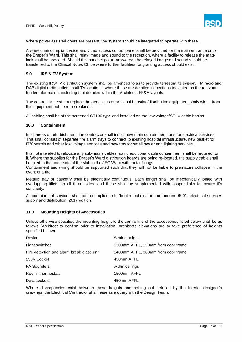
RHND – West Hill, Putney
M&E Tender Specification Page 87 of 156
Where power assisted doors are present, the system should be integrated to operate with these. A wheelchair compliant voice and video access control panel shall be provided for the main entrance onto the Draper’s Ward. This shall relay image and sound to the reception, where a facility to release the mag-lock shall be provided. Should this handset go un-answered, the relayed image and sound should be transferred to the Clinical Notes Office where further facilities for granting access should exist. 9.0 IRS & TV System The existing IRS/TV distribution system shall be amended to as to provide terrestrial television, FM radio and DAB digital radio outlets to all TV locations, where these are detailed in locations indicated on the relevant tender information, including that detailed within the Architects FF&E layouts. The contractor need not replace the aerial cluster or signal boosting/distribution equipment. Only wiring from this equipment out need be replaced. All cabling shall be of the screened CT100 type and installed on the low voltage/SELV cable basket. 10.0 Containment In all areas of refurbishment, the contractor shall install new main containment runs for electrical services. This shall consist of separate fire alarm trays to connect to existing hospital infrastructure, new basket for IT/Controls and other low voltage services and new tray for small power and lighting services. It is not intended to relocate any sub-mains cables, so no additional cable containment shall be required for it. Where the supplies for the Draper’s Ward distribution boards are being re-located, the supply cable shall be fixed to the underside of the slab in the JEC Ward with metal fixings. Containment and wiring should be supported such that they will not be liable to premature collapse in the event of a fire.
Metallic tray or basketry shall be electrically continuous. Each length shall be mechanically joined with overlapping fillets on all three sides, and these shall be supplemented with copper links to ensure it’s continuity.
All containment services shall be in compliance to ‘health technical memorandum 06-01, electrical services supply and distribution, 2017 edition.
11.0 Mounting Heights of Accessories Unless otherwise specified the mounting height to the centre line of the accessories listed below shall be as follows (Architect to confirm prior to installation. Architects elevations are to take preference of heights specified below).
Device Setting height
Light switches 1200mm AFFL, 150mm from door frame
Fire detection and alarm break glass unit 1400mm AFFL, 300mm from door frame
230V Socket 450mm AFFL
FA Sounders within ceilings
Room Thermostats 1500mm AFFL
Data sockets 450mm AFFL
Where discrepancies exist between these heights and setting out detailed by the Interior designer’s drawings, the Electrical Contractor shall raise as a query with the Design Team.
RHND – West Hill, Putney
M&E Tender Specification Page 88 of 156
12.0 Electrics for Mechanical Services
Power shall also be provided as necessary to serve the items of mechanical plant. Final connection to items of plant shall be by means of localised forms of isolation rated to suit the equipment being supplied in accordance with BS 7671.
Each appliance / equipment shall be switched and shall be labelled as to their use. They shall be supplied complete with metal clad faceplates with neon indicator lamps and back boxes suitable for surface mounting. The positions and quantity of these supplies shall be as per the mechanical design.
13.0 Earthing & Bonding
The earthing system shall be provided to BS 7671
All water, gas, electrics shall all be bonded by the contractor to the main earth. The bonding connections shall be made as close as possible to the point of entry of the gas and/or water services into the building. Connections to the pipework of other services shall be by means of clamps complying with BS 951.
All metal containment and metal enclosures, the sheaths of all metallic covered cables, the cases and enclosure of all switchgear, fuse gear and all apparatus of an electrical nature shall be so connected as to effectively form a continuous bonded earthing system, directly connected at the earth point.
All non-metallic joints in pipes and ductwork shall be bridged with a 4.0mm² bonding connection. The Contractor shall be responsible for ensuring that the complete system of conduit, trunking, pipework, etc., together with all accessories shall have sufficient metallic connection to ensure earth continuity throughout the entire installation.
14.0 Samples
The contractor shall provide a sample of each of the light fixtures/fittings including a sample of each accessory/wiring device to be signed off by the client and architect prior to placing orders on the required quantities.
The cost for providing samples shall be detailed on the tender summary.
15.0 Testing and Commissioning
The Contractor shall engage a Testing Engineer whose function shall be to monitor and oversee the testing and commissioning of all electrical services.
The scope of the involvement of the services commissioning engineer shall encompass the following:-
i. Provide method statements for testing and commissioning all the electrical systems.
ii. Liaise with manufacturers and suppliers to produce a commissioning procedure document.
iii. To be satisfied to the satisfactory physical application of the tests in terms of standard, location, duration, quantity and frequency etc., and to query same as appropriate.
iv. Obtain and review copies of test records
v. To attend and witness all testing and commissioning procedures, as undertaken by the Contractor
vi. Witness demonstration of system performance
vii. Confirm that the test and commissioning records represent a true and accurate record of the tests carried out and the results obtained
viii. Prepare a brief technical report of the results of the testing and commissioning exercises and to certify that the installation is operational and performing in accordance with the design criteria
ix. Prepare a brief technical report of the results of the testing and commissioning exercises and to certify that the installation is operational and performing in accordance with the specification and the specialist supplier’s recommendations.
x. Prepare operating and maintenance manuals and record drawings as indicated in the Preliminaries

RHND – West Hill, Putney
M&E Tender Specification Page 89 of 156
Specification Section.
The Contractor shall provide the necessary labour, material and instruments for carrying out these tests and shall give the Consultant ten working days’ notice of the date it is proposed to carry out the test.
The Contractor shall then commence the installation and shall notify the Consultant that the systems are operating according to the intent of the contract.
Testing and inspection shall be carried out in the following sequences:
i. Continuity of final circuit conductors
ii. Continuity of protective conductors, including main and supplementary equipotential bonding.
iii. Earth Electrode resistance
iv. Insulation resistance
v. Insulation of site-built assemblies
vi. Protection by electrical separation
vii. Protection by barriers or enclosures provided during erection
viii. Insulation of non-conducting floors and walls
ix. Polarity
x. Earth fault loop impendence
xi. Operation of residual current devices and fault-voltage operated protective devices.
The Contractor shall submit the results of the test to the Consultant on an Inspection Certificate of the type described in the Regulations within seven days of the date of testing.
The Contractor shall also check the labelling of circuits in the distribution boards and switchboards, check that there is no cross circuits and that all fuse and MCB sizes are correct.
The Contractor shall also allow for testing the installation whilst work is in progress or as instructed by the Main Contractor and Consultant, and in particular, the following tests much be carried out:
i. In the case of concealed sections of the installation, these shall be inspected and tested before being concealed.
ii. Where cables are run behind non-accessible ceilings, tests must be carried out immediately after the ceiling is fixed and before decorations commence.
iii. Inspection and testing of conduits and trunking as previously specified. In cases where the installations are tested and commissioned in sections, the Contractor shall repeat final demonstration to the satisfaction of the Consultant that tall sections of the works already demonstrated separately are capable of simultaneous operation in accordance with the requirements of the contract under both normal and emergency power.
The Contractor shall submit the results of the test to the Consultant on an Inspection Certificate of the type described in the Regulations within seven days of the date of testing.
The Contractor shall also check the labelling of circuits in the distribution boards and switchboards, check that there is no cross circuits and that all fuse and MCB sizes are correct.
16.0 Preferred Manufacturers & Specialist Installers
The Contractor shall provide plant and equipment based on the following list of preferred and approved manufacturers and suppliers. Alternative suppliers may be considered subject to a technical submission by the Contractor, but these shall be quoted separately and in addition to one of the preferred companies.
The Employer and his agents are under no obligation to accept any alternative manufacturers and suppliers and all submissions are made at the Contractors own risk and cost. The completed tender will be deemed to have included for equipment and other services as specified herein.
Accessories
Plant room areas conduit and accessories shall be surface mounted
All other areas shall be recessed and flush mounted.

RHND – West Hill, Putney
M&E Tender Specification Page 90 of 156
Final Distribution boards Schneider Electric
General & Emergency Lighting Refer to BSD drawings for back of house luminaires and emergency lighting and exit signs and Interior Designers schedule for front of house luminaires.
Electrical Accessories MK Logic Plus
External Accessories MK Commando Safety Switch
All plant rooms and ceiling voids. MK Metal clad Plus
Floor outlets Cable Duct 700 Series
Cables Firetuff
Prysmian
Draka
Cable Markers & Labels Critchley Ltd 01453 882451
Audio Visual Systems To be advised
Data Network Contractor To be advised
Wi- Fi Contractor To be advised
Fire Alarms systems Contractor Protec Fire Detection Plc. Protec House Churchill Way Nelson Lancs. BB9 ERT
Light Fittings As BSD/Interior Designers Schedule
Emergency Lighting As BSD schedule
17.0 Services Interface Boundaries and Equipment Supplied by Others
The following list identifies those elements having an interface with the services within the building but which are assumed to be supplied as part of the FF&E works budget.
1. Point of sale system: - Containment and cabling only are provided (Equipment is provided as part of FF&E budget).
2. Telecommunications system: - Containment and cabling only are provided (Equipment is provided as part of FF&E budget).
3. Front of House luminaires / Chandeliers and lamps (detailed by the Interior Designer) . Supplied as part of FF&E budget.

RHND – West Hill, Putney
M&E Tender Specification Page 91 of 156
810.000 FIRE ALARMS/SMOKE CONTROL PANELS
810.014 SYSTEM DRAWINGS:
• As schedule reference Section 100.802 – Tender Drawings
810.015 FIRE ALARM/SMOKE CONTROL SYSTEM:
• Application
• Specialist
• Develop design, supply and install fire alarm system to
• BS 5839-1.
• BS 5839-6.
• Building Regulations document B
• Fire Authority requirements.
• Provide fire alarm system to
• Enhance safety of occupants.
• Reduce loss of property.
810.040 FIRE ALARM SYSTEM - STANDBY POWER SUPPLIES:
• Application
• Manufacturer and reference
• Or approved equivalent.
• Standard
• BS 5839-1.
• BS EN 54-4.
• Standby
• Secondary batteries and battery charger.
• Mains operated with standby primary battery.
810.060 FIRE ALARM SYSTEM - HEAT DETECTORS, POINT TYPE:
• Type
• Application
• Manufacturer and reference
• Or approved equivalent.
• Standard
• BS EN 54-5.
• BS EN 62080.
• Heat sensitive element
• Fixed temperature (static) element.
• Rate-of-rise of temperature and fixed temperature element.
• Temperature setting
• 43oC.

RHND – West Hill, Putney
M&E Tender Specification Page 92 of 156
810.070 FIRE ALARM SYSTEM - SMOKE DETECTORS:
• Type
• Application
• Manufacturer and reference
• Or approved equivalent.
• Standard
• BS 5446-3.
• BS EN 54-7.
• BS EN 14604.
• BS EN 62080.
• Type
• Point.
• Sampling.
• Class
• Ionisation chamber smoke detectors.
• Optical detectors.
• Power supply
• Internal.
• External
• Interconnection with other devices
• Alarm silencing
810.080 FIRE ALARM SYSTEM - SOUNDERS:
• Type
• Application
• Manufacturer and reference
• Or approved equivalent.
• Standard
• BS EN 54-3
• BS EN 62080.
• Type
• Bell.
• Colour
• Fire red.
• Finish
• Weather proof.
• Internal.
810.085 FIRE ALARM SYSTEM - VISIBLE ALARMS:
• Type
RHND – West Hill, Putney
M&E Tender Specification Page 93 of 156
• Application
• Manufacturer and reference
• Or approved equivalent
• Standard
• BS EN 54-2.
• Audio-visual alarm unit
• Flashing.
• High power LED.
• Xenon.
• Power supply
• Loop powered
• Analogue addressable.
• Combined
810.100 FIRE ALARM SYSTEM - RECORD DRAWINGS AND OPERATING INSTRUCTIONS:
Provide instructions on use of installation to person responsible for use of premises. Supply the user with a logbook certificate of installation and commissioning and record drawings in accordance with BS 5839.
• Circuit diagrams of fire alarm system.
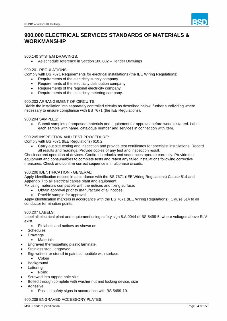
RHND – West Hill, Putney
M&E Tender Specification Page 94 of 156
900.000 ELECTRICAL SERVICES STANDARDS OF MATERIALS & WORKMANSHIP 900.140 SYSTEM DRAWINGS:
As schedule reference in Section 100.802 – Tender Drawings 900.201 REGULATIONS: Comply with BS 7671 Requirements for electrical installations (the IEE Wiring Regulations).
Requirements of the electricity supply company.
Requirements of the electricity distribution company.
Requirements of the regional electricity company.
Requirements of the electricity metering company. 900.203 ARRANGEMENT OF CIRCUITS: Divide the installation into separately controlled circuits as described below, further subdividing where necessary to ensure compliance with BS 7671 (the IEE Regulations). 900.204 SAMPLES:
Submit samples of proposed materials and equipment for approval before work is started. Label each sample with name, catalogue number and services in connection with item.
900.205 INSPECTION AND TEST PROCEDURE: Comply with BS 7671 (IEE Regulations) 610.2.
Carry out site testing and inspection and provide test certificates for specialist installations. Record all results and readings. Provide copies of any test and inspection result.
Check correct operation of devices. Confirm interlocks and sequences operate correctly. Provide test equipment and consumables to complete tests and retest any failed installations following corrective measures. Check and confirm correct sequence in multiphase circuits. 900.206 IDENTIFICATION - GENERAL: Apply identification notices in accordance with the BS 7671 (IEE Wiring Regulations) Clause 514 and Appendix 7 to all electrical cables plant and equipment. Fix using materials compatible with the notices and fixing surface.
Obtain approval prior to manufacture of all notices.
Provide sample for approval. Apply identification markers in accordance with the BS 7671 (IEE Wiring Regulations), Clause 514 to all conductor termination points. 900.207 LABELS: Label all electrical plant and equipment using safety sign 8.A.0044 of BS 5499-5, where voltages above ELV exist.
Fit labels and notices as shown on
Schedules
Drawings
Materials
Engraved thermosetting plastic laminate.
Stainless steel, engraved.
Signwritten, or stencil in paint compatible with surface.
Colour
Background
Lettering
Fixing
Screwed into tapped hole size
Bolted through complete with washer nut and locking device, size
Adhesive
Position safety signs in accordance with BS 5499-10. 900.208 ENGRAVED ACCESSORY PLATES:

RHND – West Hill, Putney
M&E Tender Specification Page 95 of 156
Engrave accessory plates and specialist items as shown in the Schedules or on the Drawings.
Use 6mm high letters with engraving coloured red. 900.209 SCHEMATIC DIAGRAMS: Provide a purpose made schematic diagram permanently fixed showing the connections of the equipment and plant. 900.210 DISTRIBUTION BOARDS IDENTIFICATION: Identify every outgoing way with a renewable circuit chart in a transparent plastic envelope permanently fitted inside distribution board cover. Clearly indicate in typed script, circuit identification number, cable size, fuse or circuit breaker rating and a description of item supplied and area supplied by circuit. 900.211 CABLE IDENTIFICATION: Provide all cables, other than final sub-circuit wiring with labels fixed at each end of cable, either side of wall and floor penetrations and at approximately 10m intervals. Ensure labels show reference number of cable. 900.213 CABLE SHEATH IDENTIFICATION - EXTERNAL: Identify cable sheaths for various services in accordance with NJUG7. 900.214 OFF-SITE PAINTING AND ANTI-CORROSION TREATMENTS - GENERAL REQUIREMENTS: Protect all equipment and ancillaries against corrosion. Protect ferrous metals with coatings at works. Provide all items for decorative finishing primed to suit base material and finish. 900.215 PAINT MATERIALS:
Type
Application
Apply paints in accordance with manufacturer's instructions and to BS 6150.
Use paint materials 900.216 SPECIAL PROTECTIVE FINISHES:
Type
Application
Provide special protective finishes in accordance with manufacturer's instructions. 900.217 ELECTRICAL EQUIPMENT SCHEDULES:
Schedule reference V90-Electrical equipment
Schedule reference Y61-Cables
Schedule reference Y71-Distboards
Schedule reference Y73-Luminaires
Schedule reference
Location 900.301 STEEL CONDUIT AND FITTINGS:
Type
Application
Manufacturer and reference
Or approved equivalent.
Standard
BS EN 61386-21.
Ends
Threaded.
Plain threadable.
Size in accordance with BS 7671 (IEE regulations).
Fittings
Use adaptable boxes of 100mm x 100mm x 38 mm minimum size.
Use adaptable boxes of 100mm x 100mm x 50mm minimum size.
Use couplers and externally screwed brass bushes to connect conduit to loop-in circular conduit boxes.
Use washers with flanged couplers.
Protection class/finish

RHND – West Hill, Putney
M&E Tender Specification Page 96 of 156
Class 2 black enamel finish.
Class 4 hot dipped galvanized.
Mounting/support
Installation
Use maximum practical lengths to minimise number of joints. Form bends by machine and remove burrs from cut ends.
Use bends and/or junction boxes at changes of direction. Do not use elbows or tees of any sort without approval.
Fix securely with boxes fixed independently of conduit.
Tightly screw all joints to ensure electrical continuity, with no thread showing. Use expansion couplings where conduit crosses movement joints in structure.
900.302 THERMOPLASTIC (PVC) CONDUIT AND FITTINGS:
Type
Application
Manufacturer and reference
Or approved equivalent.
Standard - BS EN 61386-21.
Strength
Light duty
Heavy duty.
High impact.
Size in accordance with BS 7671 (IEE regulations).
Shape
Round.
Oval.
Colour
Black.
White.
Jointing
Push fit.
Solvent welded.
Push fit and solvent welded.
Screwed.
Fittings
Provide boxes with earthing terminal.
Provide weatherproof boxes.
Mounting/support
Installation
Use maximum practical straight lengths to minimise number of joints.
Use proprietary bends and/or junction boxes at changes of direction. Do not use elbows, tees or site formed bends without approval.
Fix securely with boxes fixed independently of conduit.
Form secure joints, using expansion couplings where recommended by manufacturer, and connectors at equipment, terminal fittings, etc.
900.306 FLEXIBLE CORDS:
Type
Application
Manufacturer and reference
Or approved equivalent.
BASEC certified.
Standard
Sheathed 300/500V 90oC to BS 6500
Thermoplastic (PVC) insulated cord 450/750V to BS 7919
Glass Fibre insulated 450/750V to BS 7919 900.307 INSULATED CABLES:
RHND – West Hill, Putney
M&E Tender Specification Page 97 of 156
Type
Application
Manufacturer and reference
Or approved equivalent.
BASEC certified.
Type
Copper conductors.
Single core.
Multi-core
Armoured.
Unarmoured.
Sheathed.
LSF.
HOFR.
Unsheathed.
Standard
General purpose 450/750V to BS 6004.
Internal wiring 300/500V to BS 6004.
Flat twin and earth to BS 6004.
600/1000V to BS 5467.
600/1000V to BS 6724.
450/750V to BS 7211.
Flat twin and earth to BS 7211.
Cable glands
BS EN 50262.
Type
Sealed outer sheath.
Sealed inner sheath.
Sealed inner and outer sheath.
Complete with earthing lug.
Electrical bond for metallic sheath. 900.308 MINERAL INSULATED LV CABLES:
Type
Application
Manufacturer and reference
Or approved equivalent.
BASEC certified.
Type
Bare.
Sheathed
Standard
500V light duty to BS EN 60702-1 Section 14.
750V heavy duty to BS EN 60702-1 Section 15.
Cable glands
Use seals and glands to BS EN 60702-2.
Type
Externally threaded.
Internally threaded.
Earth continuity conductor.
Seal temperature rating
105oC.
150oC.
250oC. 900.309 POLYETHYLENE INSULATED TELECOMMUNICATIONS CABLES:
Type
RHND – West Hill, Putney
M&E Tender Specification Page 98 of 156
Application
Manufacturer and reference
Or approved equivalent.
BASEC certified.
Standard
Size 0.4mm
Size 0.5mm
Size 0.63mm
Size 0.9mm 900.310 COAXIAL CABLES:
Type
Application
Manufacturer and reference
Or approved equivalent.
BASEC certified.
Standard - BS EN 50117.
URM Number
Connectors
BS 3041-12.
Connect in accordance with BS 7587.
UHF to BS 3041-12.
BNC. 900.311 CABLE JOINTING SUNDRIES: Use terminations conforming to the BS 4579-2 or BS EN 61238-1. Use tapes to BS 3924 or BS EN 60454.
Use twist on connectors to BS EN 60998-2-4. 900.314 PERFORATED CABLE TRAY:
Type
Application
Manufacturer and reference
Or approved equivalent. Support all cables throughout their length using cable tray, firmly fixed to building fabric. Ensure cable tray allows for spacing in accordance with BS 7671 for the design current of the cable.
Standard BS EN 61537 Classification Type
Flanged.
Return flanged.
Perforations and thickness
Manufacturer's standard pattern and thickness. Fittings Use factory made fittings throughout of same material, type, pattern, finish and thickness as cable tray.
900.401 INSTALLING CONDUIT IN CONCRETE: Fix securely to reinforcement and fix boxes to formwork to prevent displacement. Depth of concrete cover not less than indicated for reinforcement. 900.402 INSTALLING TRUNKING: Remove burrs from cut trunking ends. 900.403 DRAINAGE OF CONDUIT: Provide drainage outlets at lowest points in conduit installed externally and in locations where condensation may occur. 900.404 APPEARANCE:

RHND – West Hill, Putney
M&E Tender Specification Page 99 of 156
Arrange conduit and trunking, plumb where vertical, neatly parallel with other service runs and the structure. 900.405 EXPANSION AND SETTLEMENT JOINTS: Make provision at expansion and settlement joints for movement. Use manufactured expansion couplings. 900.406 SPACING: Install conduit, trunking and equipment clear of other services with minimum spacings:-
to steam - 300mm, other services - 150mm and above radiators - 1000mm. Ensure trunking and conduit is independently supported from building fabric. Obtain approval for supports. 900.407 CABLE ROUTES:
Ensure cable routes are
Straight, vertical or horizontal and parallel to walls.
In approved locations where exposed to view. Conceal cables wherever possible.
Positioned at least 150 mm clear of other services. Locate cables running parallel and adjacent to heating pipes below pipes.
Install
concealed horizontal runs in walls within 150 mm of ceiling or between 150 and 300 mm of floor.
concealed vertical cable runs to wall switches and outlets in line with accessory. 900.408 CABLE INSTALLATION - GENERAL:
Do not commence internal cabling until the building is enclosed and weatherproof.
Install cables neatly and securely, adequately protected against accidental damage, adverse environmental conditions, mechanical stress and deleterious substances.
Install cables without joints other than at equipment and terminal fittings. Do not use junction boxes without approval.
Sleeve cables passing through masonry walls with conduit bushed at both ends.
Do not run cables in spaces where they will be surrounded or covered by insulation. 900.409 PROTECTIVE CONDUCTORS: Use cable conductors throughout; do not use conduit or trunking as protective conductors. 900.410 CABLE INSTALLATION - ARMOURED CABLE: Handle and install carefully to prevent damage to sheath and armouring.
Do not install if cable and ambient temperature are, or have been for the last 24 hours, below 0oC. Fit galvanized steel guards where cables are liable to mechanical damage. Bond armour to equipment and main earthing system. Make moisture proof connections to apparatus using sealed glands and thermoplastic (PVC) shrouds. 900.411 CABLE INSTALLATION - THERMOPLASTIC (PVC) SHEATHED CABLES: Do not install cables when temperature is near or below freezing. Do not install in cavities of external walls. Fit insulating cable glands at entries to equipment. Terminate cable sheaths within boxes. 900.412 CABLE INSTALLATION - MICC CABLE: Neatly and carefully dress cable into position using tools recommended by cable manufacturer. Avoid corrugating sheath when bending. Connect to equipment and boxes with shrouded glands. Fix cables with clips recommended by manufacturer ensuring that cable is fixed within 150 mm of bends and connections. As soon as a length of cable has been installed, fit permanent seals and immediately carry out an insulation test between conductors or between any conductor and cable sheath. Repeat test between 24 and 48 hours later. Only infinity readings will be accepted. Replace any cable which fails and repeat tests. 900.415 CABLES IN PLASTER: Cover with galvanized steel channel nailed to background. 900.416 CABLES IN VERTICAL TRUNKING/DUCTS: Support with pin racks or cleats at each floor level or at 5m vertical centres, whichever is less.

RHND – West Hill, Putney
M&E Tender Specification Page 100 of 156
Provide and fix heat barriers at not more than 5m centres where fire resisting barriers are not indicated. 900.417 CABLES IN ACCESSIBLE ROOF SPACES: Cables running across ceiling joists to be fixed to timber battens nailed to joists. 900.418 TESTING BURIED CABLES: Test continuity and insulation of buried cables immediately before and after back-filling. Test continuity and insulation of buried cables prior to handover.
900.501 LIGHTING AND POWER SCHEDULES:
Supply lamps and luminaires as
schedule reference Y73-Luminaires
schedule reference
drawing reference
Supply consumer units/distribution boards as
schedule reference Y71-Distboards
schedule reference
drawing reference
Supply electrical accessories as
schedule reference
drawing reference 900.502 CONSUMER CONTROL UNITS:
Type: Single Phase and Neutral
Application
MK
Or approved equivalent.
Standard - BS EN 60439-3.
Main control
Switch disconnector.
Residual current circuit breaker.
Number of ways.
One per circuit plus 2 spares.
Permanently label each way to identify circuit and rating.
Circuit protection
Miniature circuit breakers to BS EN 60898.
Type
Rating (A)
RCBO to BS EN 61009
Tripping current
Tripping time
Breaking capacity
Overcurrent protection
Enclosure
Degree of protection to BS EN 60529
Manufacturer's standard. 900.504 FUSES: Supply fuses including fuse carrier, bases and associated components to BS EN 60269-1 and BS 88. 900.505 ISOLATING SWITCHES:
Type
Application
MK
Or approved equivalent.
Standard
Utilisation category and making capacity to BS EN 60669-2-4, with earth terminal in enclosure.
HBES systems, utilization category and marking capacity to BS EN 50428, with earth terminal in

RHND – West Hill, Putney
M&E Tender Specification Page 101 of 156
enclosure.
Switch type
Rocker bar.
Toggle.
Rating
15A.
20A.
30A.
45A.
Pole configuration
SP.
DP.
Ancillaries
Neon indicator with red lens.
Cord outlet with cord grip. 900.506 LUMINAIRES:
Type
Application
Manufacturer and reference
Or approved equivalent.
Standard
BS 4533
Part
BS EN 13032-1.
BS EN 60598.
Part
Provide exit signs to BS 5499-4.
BS EN 62301.
Classification
BS EN 60598, Part
Ensure luminaires of same types have same photometric performance.
Accessories
Provide secondary support for all components so they are retained when their primary fixing is released.
Incorporate integral photo-cell on luminaires 900.507 LAMPHOLDERS:
Type
Application
Manufacturer and reference
Or approved equivalent.
Standard
BS 7895
BS EN 61184, B22.
BS EN 60400.
BS EN 60238, E27.
Fixing
Bracket
Suspension.
Finish
Material
Heat resistant moulded plastic.
Brass casing/porcelain interior.
Ancillaries
Cord grip.
Lampshade ring.
Protective lampshade ring.
Use lamp holder suitable for conduit box when mounted directly to conduit system backplate.

RHND – West Hill, Putney
M&E Tender Specification Page 102 of 156
Ensure lamp holders in luminaires of similar type and rating are identical. Installation Securely mount lamp holder in luminaire. Ensure metal lamp holders incorporate an earthing terminal. Ensure phase conductor is connected to centre contact of Edison screw lamp holders.
900.508 CONTROL GEAR AND COMPONENTS:
Type
Application
Manufacturer and reference
Or approved equivalent.
Standard
Provide fluorescent lamp ballasts to
BS EN 61347-2-8 and BS EN 60921.
BS EN 61347-2-4, BS EN 61347-2-5, BS EN 61347-2-6, BS EN 61347-2-7 and BS EN 60925 for d.c. supplied electronic ballasts.
BS EN 61347-2-3 and BS EN 60929.
Supply thermal protectors for ballasts for tubular fluorescent lamps to BS EN 60730-2-3.
Provide discharge lamp ballasts to BS EN 61347- 2-9 and BS EN 60923.
Provide starters to BS EN 61347-2-1 and BS EN 60927.
Provide capacitors to BS EN 61048 and BS EN 61049.
Control gears for LED modules, BS EN 61347-2-13.
Terminals
Use screw terminals for supply cables and circuit protective conductors, sized to terminate up to three 2.5mm diameter conductors. Provide separate terminal blocks for each incoming circuit.
Ensure control gear and components are suitable for lamp type, wattage and starting characteristics.
Comply with BS EN 55015 for interference.
Remote control gear Locate remote control gear in separate lockable cabinet of sheet steel with same degree of protection and finish specified for luminaire.
Comply with manufacturer's recommendations for maximum cable length between gear and lamp. 900.509 LAMPS:
Type
Application
Manufacturer and reference
Or approved equivalent.
Standard
Tungsten filament lamps
BS EN 60064.
BS EN 60432-1.
Tungsten halogen lamps, BS EN 60432-2.
Fluorescent lamps, BS EN 60081.
High pressure mercury vapour lamps, BS EN 60188 and BS EN 62035.
High pressure sodium vapour lamps, BS EN 62035.
Low pressure sodium vapour lamps, BS EN 60192 and BS EN 62035.
Metal halide lamps, BS EN 62035.
LED lamps Ensure that lamps of each type are from the same manufacturer. 900.510 LUMINAIRE CONNECTORS:
Type
Application
Manufacturer and reference
Or approved equivalent.
Rating
2A.
5A.
Connector type
RHND – West Hill, Putney
M&E Tender Specification Page 103 of 156
Ceiling rose to BS 67.
3 pin plug/socket to BS 546.
Captive cord grip type plug/socket (3 or 4 pin), to BS 5733.
Load carrying capacity 900.511 SUPPORT SYSTEM:
Type
Application
Manufacturer and reference
Or approved equivalent.
Minimum 20mm conduit as main conduit.
10mm diameter threaded rod.
Chain
Flexible cord
Wall brackets 900.514 ENCLOSURES FOR ELECTRICAL ACCESSORIES:
Type
Application
Manufacturer and reference
Or approved equivalent.
Standard - BS 4662, BS EN 60670-23 or BS 5733
Pattern
Flush.
Surface.
Floor.
Panel.
Mounting
Adjustable steel grid.
Direct to enclosure.
Material and finish
Cast iron with finish as conduit system.
Pressed steel.
White moulded plastic.
Impact resistant moulded plastic.
Cover plate finish
Brass with matt chrome surface.
Brass
Moulded plastic colour
Cover plate pattern
Overlapping.
Surface type.
Architrave.
Engraving 900.515 LIGHTING SWITCHES:
Type
Application
MK
Or approved equivalent.
Standard
BS EN 60669-1, with earth terminal in enclosure.
HBES systems BS EN 50428, with earth terminals in enclosure.
Switch type
Gang
Rocker bar
Dolly
Cylinder lock.

RHND – West Hill, Putney
M&E Tender Specification Page 104 of 156
Secret key.
Pull cord.
Dimmer.
Press on, press off.
Rotary operated through sealing gland.
Rating
6A.
10A.
15A.
20A.
Ancillaries
Red indicator, illuminated when 'ON'.
White indicator illuminated when 'OFF'.
Protective shrouds to rocker bars.
Operating keys.
Blank inserts.
Switch mechanism
Snap action microgap.
Two position.
Return to centre.
Biased in one direction.
Timed off.
Pole configurations
Single pole.
Double pole.
2 way.
Intermediate. 900.516 SWITCHED FUSE CONNECTION UNITS:
Type
Application
MK
Or approved equivalent.
Standard
BS 1363-4.
Double pole switching.
Unit type
Rocker bar
Dolly.
Ancillaries
Red indicator lamp.
Fuses to BS 1362, sized
Cord outlet and cord grip. 900.517 COOKER CONTROL UNITS:
Type
Application
MK
Or approved equivalent.
Standard - Cooker control unit to BS 4177. 900.518 SOCKET OUTLETS:
Type
Application
MK
Or approved equivalent.
Standard
BS 1363-2.
RHND – West Hill, Putney
M&E Tender Specification Page 105 of 156
BS EN 60669.
HBES systems, BS EN 50428.
Type
Socket outlet.
Connection unit.
Switched.
Rocker bar
Dolly.
DP switch.
1 gang.
2 gang.
Ancillaries
RCD.
Sensitivity
30mA.
10mA.
Fuse
Cord grip.
Cord outlet.
Neon indicator.
Spring loaded dust flap.
Plug tops.
Screw type weathering cap and chain. 900.519 CORD OUTLETS:
Type
Application
MK
Or approved equivalent.
Standard - BS 5733.
Rating
Pole configuration
DP.
TPN.
Ancillaries
Cord grip. 900.520 TELEPHONE OUTLET SOCKETS:
Type
Application
MK
Or approved equivalent.
Standard - to the requirements of the telephone service provider
Size
Standard.
Miniature.
Circuit configurations
Master.
Dual master.
Twin master.
Dual secondary.
Twin secondary.
Secondary.
Connections
Insulation displacement type. 900.521 AERIAL SOCKETS:
Type

RHND – West Hill, Putney
M&E Tender Specification Page 106 of 156
Application
MK
Or approved equivalent
Standard
BS EN 50083 and BS EN 60728.
Circuit configurations
Twin UHF.
Single UHF.
Twin VHF.
Single VHF.
Single DAB.
Dual UHF and DAB.
Dual VHF and FM.
Satellite IF.
Combined with telephone socket.
Characteristics
Insertion loss.
Isolation.
Ancillaries
Safety isolation to CAI recommendations for communal aerial systems. 900.522 LOW VOLTAGE ISOLATING TRANSFORMER UNITS:
Type
Application
Manufacturer and reference
Or approved equivalent.
Standard
BS EN 61558-1 and BS EN 61558-2-23.
BS EN 61558
Rating
Input
Output
Ancillaries
Plug and socket.
DP switch primary supply.
Centre tapped secondaries.
Secondary side fusing. 900.523 SHAVER POINTS:
Type
Application
MK
Or approved equivalent.
Provide shaver points, internally switched by plug insertion.
Standard
BS 4573.
BS EN 61558
BS EN 61558-1 and BS EN 61558-2-23.
Rating
0.2A.
20VA. 900.524 INDICATOR LAMPS:
Type
Application
Manufacturer and reference
Or approved equivalent.
Lamp

RHND – West Hill, Putney
M&E Tender Specification Page 107 of 156
Moulded plastic lens cover, colour
Lens retaining rings.
Chrome plated brass.
Moulded plastic. 900.601 LAMPS AND LUMINAIRES INSTALLATION: Install luminaires in horizontal plane unless otherwise shown. Ensure luminaires are clean. Ensure classification of luminaires is appropriate.
Install recessed and semi-recessed luminaires as manufacturer's details.
Install wall mounted luminaires at height
Support and fixing
Where luminaire is supported from conduit, provide a conduit box forming an integral part of conduit system at each point of suspension. Where conduit enters luminaire, use backnuts and washers to secure luminaire to conduit.
Where luminaire is supported from trunking, use appropriate clamps or brackets.
Use washers, nut and lock-nut at top and bottom of rod for rod suspensions.
Use hook cover for suspension of chain from circular conduit box.
Use manufacturer's recommended chain hook for connection to luminaires.
Suspend flexible cord from ceiling rose.
Support luminaires directly from building fabric
Support luminaires Do not support luminaires directly from any flammable non-metal or heat sensitive materials. Ensure suspensions are vertical unless otherwise shown. 900.602 CONNECTIONS TO LUMINAIRES: Connect circuit wiring to luminaires. Use grommet where cables enter luminaire body. Connect the earthing terminal of Class 1 luminaires to the circuit protective conductor of the supply circuit. Clip loose wiring within luminaire, at 300mm intervals.
Conduit, rod or chain suspension.
Application
Terminate in terminal block within supporting conduit box. Use flexible cord from terminal block to luminaire, installed within tube of conduit suspension. Secure cord to rod or chain without weaving cord through chain.
Terminate at supply terminals of luminaire.
Direct to trunking
Application
Terminate in terminal block in an adaptable box located on side of trunking. Use flexible cord from terminal block to luminaire.
Terminate circuit wiring at supply terminals of luminaire.
Suspended from trunking
Application
Fit plug and socket to BS 546, adjacent to, or on side of, trunking. Terminate circuit wiring at socket. Take flexible cord from plug to supply terminals of luminaire.
Recessed
Application
Terminate at plug and socket to BS 546, located not more than 500mm from the access through the ceiling. Use flexible cord from plug to supply terminals of luminaire.
Terminate in terminal block within conduit box. Install flexible wiring to luminaire.
MICS Cable
Application
Fix cable gland to luminaire and continue conductors to supply terminals of luminaire.
Direct fixing 900.603 ELECTRICAL ACCESSORY INSTALLATION: Provide CPC between earth lug on metal box and accessory except for plastic accessories. Ensure there is no damage to accessories during installation. Protect surface mounted accessories from painting. Install front plates of flush mounted accessories after painting.
RHND – West Hill, Putney
M&E Tender Specification Page 108 of 156
Align accessories to building finishes. Mount grouped accessories in line, parallel and equidistant.
900.701 ELECTRIC HEATERS:
Type
Application
Manufacturer and reference
Or approved equivalent.
Supply electric heaters as shown on
schedule reference V51-Elec htrs
schedule number
drawing number
Standard - BS 3456 or BS EN 60335.
System in accordance with BS EN 14337
Design
Installation
Heater type
Storage heater, BS EN 60335-2-61.
Fan assisted BS EN 60335-2-61.
Night storage water heater.
Panel heater to BS EN 60335-2-30.
Panel oil filled radiator to BS EN 60335-2-30.
Column oil filled radiator to BS EN 60335-2-30.
Tubular to BS EN 60335-2-30.
Cast iron air warmer to BS EN 60335-2-30.
Convector to BS EN 60335-2-30.
Fan heater, to BS EN 60335-2-30.
Air curtain.
Electric towel rail, BS EN 60335-2-43.
Heat lamp to BS EN 60335-2-30.
Mounting
Floor.
Wall.
Ceiling.
Concealed.
Construction
Manufacturer's standard
Materials
Manufacturer's standard
Finish
Manufacturer's standard
Controls
Manufacturer's standard.
Proportional control
Thermostat
Thermostat setting selector
Frost protection thermostat setting.
Thermal cut-out.
On/off switch.
Indicator lamps
Timer
Programmer
Characteristics
General
Input rating (kW)
Output rating (kW)
Output steps

RHND – West Hill, Putney
M&E Tender Specification Page 109 of 156
Dimensions
Supply connection
Storage heaters
7 hour charge acceptance, (kW hours)
Maximum output, (W)
Minimum output, (W)
Half life, (hrs)
Maximum case temperature, (oC)
Case emission, (W)
Weight, (kg)
Grille
Heat storage bricks, type and number
Heater elements
Sheath power density, (W/cm2)
Thermal insulation
Water capacity, (l)
Maximum water temperature, (oC)
Charge controller
Day rate charge top-up controller
Damper/boost controller
Separate room temperature sensor.
Remote controller
Non Radiant heaters
Integral with storage heater.
Integral with radiant heater.
Heater elements
Radiant heaters
Radiant element type
Infra-red.
To BS EN 60240.
Fire effect.
Quartz halogen radiant.
Secondary illumination
Reflector type
Beam angle
Lens type
Filter type
Fan and Air circuit
Fan duty, (m3/sec)
Fan duty steps
Fan type
Output air flow direction
Fan only selector.
Return air filter
Return air damper
Fresh air damper
Air mixing
Non-active air flow through heater.
Integral grilles
Accessories
Castors.
Top plate.
Flue. 900.702 INSTANTANEOUS WATER HEATER(S):
Type
Application
RHND – West Hill, Putney
M&E Tender Specification Page 110 of 156
Manufacturer and reference
Or approved equivalent
Supply and install
Electric instantaneous water heater.
Electric instantaneous water heater to BS EN 60335-2-35.
Electric instantaneous shower heater to BS 6340.
Duty - Rated output (kW)
Service
Single point.
Multipoint.
Water supply
Mains.
Cistern located
Casing finish
White vitreous enamel.
Heating element
3kW element.
6kW element.
7kW element.
9kW element.
12kW element.
18kW element - 3 phase.
24kW element - 3 phase.
Incorporating
Controls
Accessories 900.703 STORAGE WATER HEATER(S):
Type
Application
Manufacturer and reference
Or approved equivalent
Supply and install
Electric storage water heater to BS EN 60335-2-21.
Electric immersion heater to BS EN 60335-2-73.
Duty
Rated output (kW)
Capacity (litres)
Water capacity (l)
Maximum water temperature (oC)
Service
Single point.
Multipoint.
Unit type
Night storage water heater.
Water supply
Mains.
Cistern located
Casing finish
White vitreous enamel.
Heating element
Supply immersion heater complete with thermostat and
1kW element.
2kW element.
3kW element.
Incorporating
Controls
Accessories
RHND – West Hill, Putney
M&E Tender Specification Page 111 of 156
900.706 TIME SWITCHES AND PROGRAMMERS:
Type
Application
Manufacturer and reference
Or approved equivalent.
Standard - BS EN 60730-2-7.
Style
Display
Movement
Input
Accuracy
Enclosure protected to BS EN 60529
Adjustment
Automatic change-over summer time winter time.
Perpetual calendar
Manual correction and reset.
Programme options
Outputs 900.707 HEATING CONTROLS:
Application
Manufacturer and reference
Or approved equivalent.
Details
900.802 TELECOMMUNICATIONS PROVIDER: Liaise with and attend upon the Public Telecommunications Operator for provision of the telecommunications service and ensure the installation meets the PTO requirements.
Pay the PTO costs.
Payment of PTO costs by others 900.803 EXISTING TELECOMMUNICATIONS SYSTEM: Liaise with and attend upon the operation and maintenance organisation of the existing telecommunication system and ensure the installation meets all the requirements of that organisation. 900.804 TELECOMMUNICATIONS SYSTEM:
Application
Specialist
Manufacturer and reference
Or approved equivalent.
Provide telecommunications system in accordance with BS 6701. Attend to the telephone service provider's requirements during their connection of the private system to the public network.
Publicly available telephone service provider
BT.
Incoming system
PSTN
Analogue
Digital
Cable layout
Source to FDP's
FDP's to apparatus
FDP's style and capacity
Jack plug
PBX or key system
Exchange lines
Extensions

RHND – West Hill, Putney
M&E Tender Specification Page 112 of 156
Private lines
Features and Facilities
Extension numbering
Telephones
BABT approved.
Jack plug
Cordless
REN
PSTN direct connection.
Key system
Features and facilities
Pay phone
Intercommunications system
Master stations
Substations
Features and Facilities 900.826 EXISTING INSTALLATIONS EARTHING AND BONDING: Check earth continuity conductors and loop impedance values of existing installation. Report defects and elements not in accordance with BS 7671 (IEE Regulations) before connecting new or modified installations to existing supply. 900.827 ELECTRICAL INSTALLATION METALWORK: Bond together all exposed conducting parts with joints of negligible impedance. Carry out work in accordance with BS 7430, Electricity Supply Regulations, and Local Electricity Supply Authority Requirements. 900.828 EXTERNAL SOCKETS AND EQUIPMENT: Provide each circuit serving external socket outlets and sockets for external use of equipment with high sensitivity residual current device, earth leakage tripping current not exceeding 30mA. 900.829 PROTECTIVE CONDUCTORS:
Application
Provide protective and equipotential bonding conductors. Size in accordance with the BS 7671 (IEE Wiring Regulations).
Material
Copper PVC to BS 6004.
Copper LSF to BS 7211.
Bare copper.
Copper tape insulated PVC.
Copper tape insulated
Metallic screwed conduits.
Metallic trunking.
Armouring or sheathing of cables.
Protective conductor of multi-core cable. 900.833 BUILDING INCOMING SERVICES: Bond incoming services at building entry point to main earth terminal.
Water.
Gas.
Fuel Oil.
Heating pipework.
Metallic cladding.
Cable Sheaths of TV and Radio cables.
Sheaths of LV and ELV cables.
Sheaths of communications cables
Others 900.835 EQUIPOTENTIAL BONDING:

RHND – West Hill, Putney
M&E Tender Specification Page 113 of 156
Provide main and supplementary equipotential bonding conductors in accordance with BS 7671 (the IEE Wiring Regulations).

RHND – West Hill, Putney
M&E Tender Specification Page 114 of 156
1000.000 PIPELINES AND ANCILLARIES
1000.201 PIPEWORK INSTALLATION: Arrange all exposed pipe runs to present neat appearance, parallel with other pipe or service runs and building structure. Ensure all vertical pipes are plumb or follow building line. Provide lifting loops where called for by system manufacturer. Space pipe runs in relation to one another, other services runs and building structure, allow for specified thickness of thermal insulation and ensure adequate space for access to pipe joints etc. Take precautions to prevent the discharge of refrigerant gases to atmosphere. 1000.202 APPEARANCE: Arrange all exposed pipe runs to present neat appearance, parallel with other pipe or service runs and building structure, subject to gradients for draining or venting. Ensure all vertical pipes are plumb or follow building line. 1000.203 ISOLATION AND REGULATION: Provide valves, cocks and stop taps for isolation and/or regulation
where shown on drawings.
on mains to isolate major sections of distribution.
the base of all risers and drops except in cases where one item of apparatus only is served which has its own local valve or stop tap.
at points of pipe connection of all items of apparatus and equipment except where the item could conveniently be isolated or regulated by valves provided for other adjacent items.
1000.204 SPACING: Space pipe runs in relation to one another, other services runs and building structure, allow for thermal insulation and ensure adequate space for access to pipe joints, etc. Minimum clearances to pipe or pipe insulation:-
From Minimum clearance (mm)
Wall 22
Ceiling 50
Floor 150
Other pipes 25
Electrical cables, conduit, switchgear 150
1000.205 GRADIENTS: Install pipework with gradients to allow drainage and air release. Provide a means of venting the pipe system at all high points. Grade pipework to allow system to be drained. Provide a means of draining the system at all low points. 1000.206 EXPANSION AND CONTRACTION: Arrange supports and fixings to accommodate pipe movement caused by the thermal changes. Isolate pipes from structure to prevent noise or abrasion due to thermal movement. 1000.207 BENDS, SPRINGS AND OFFSETS: Machine bend and ensure that machine guides and formers are smooth and clean, free from any scores, or other damage. Deformed bends will not be accepted. 1000.208 PIPES THROUGH WALLS AND FLOORS: Enclose pipes passing through building elements, (walls, floors, partitions, etc.) concentrically within purpose made sleeves. 1000.209 PIPE SLEEVES: Cut sleeves from material same as pipe one or two sizes larger than pipe. Do not use sleeves as pipe

RHND – West Hill, Putney
M&E Tender Specification Page 115 of 156
supports. Install sleeves flush with building finish. 1000.210 TEMPORARY PLUGS AND CAPS: Seal all open ends as installation proceeds by metal, plastic or wooden plugs or caps, to prevent ingress of foreign matter. 1000.211 CAPILLARY JOINTS, COPPER PIPES: Preparation Ensure that plain ends are cut square. Reamer out bore at plain ends to full bore size. Clean plain ends with fine steel wool. Making and sealing Use specified flux ensuring no excess material used. Make joint in accordance with manufacturer's instructions. Clean off traces of flux when joint is completed. Protect building fabric from heat when forming joints.
Polyethylene sheathed pipe Follow manufacturer's recommendations to avoid damage to plastic coating. Make good with thermoplastic (PVC) tape of matching colour. 1000.212 COMPRESSION JOINTS, COPPER PIPES: Preparation Ensure that plain ends are cut square. Reamer out bore at plain ends to full bore size. Clean plain ends with fine steel wool or fine sandpaper. Then if using
Type 'A' fitting - no further preparation.
Type 'B' fitting - in accordance with fitting manufacturer's instructions. Making and Sealing In accordance with fitting manufacturer's instructions. 1000.213 SCREWED JOINTS - STEEL PIPES: Preparation Ensure that plain ends of pipe are cut square, reamer out bore and cut taper thread. Making and Sealing Coat male pipe threads with jointing compound and hemp, or PTFE tape on small sizes. Immediately after applying coating, connect with female end of socket or fitting, and tighten ensuring that coating does not intrude into pipe. Leave joint clean. 1000.214 PIPE RINGS AND CLIPS: Select type according to the application and material compatibility. 1000.215 PIPE SUPPORTS: Arrange supports and accessories for equipment, appliances or ancillary fitments in pipe runs, so that no undue strain is imposed upon pipes. Ensure that materials used for supports are compatible with pipeline materials. 1000.216 PIPE SUPPORT SPACING - COPPER PIPES:
Pipe bore (mm) Maximum support spacing (mm)
nominal horizontal vertical
15 1200 1800
22 1400 2100
28 1800 2400
35 2400 3000
42 2400 3000
54 2700 3000
1000.217 PIPE SUPPORT SPACING - STEEL PIPES:

RHND – West Hill, Putney
M&E Tender Specification Page 116 of 156
Pipe bore (mm) Maximum support spacing (mm)
nominal horizontal vertical
15 1800 2400
20 2400 3000
25 2400 3000
32 2700 3000
40 3000 3600
50 3000 3600
65 3700 4600
80 3700 4600
100 3700 4600
125 3700 5400
150 4500 5400
1000.218 PIPE SUPPORT SPACING PLASTICS PIPE:
PB & PE-X Pipe Maximum support spacing
nominal size (mm) horizontal (mm) vertical (mm)
<16 300 500
18-25 500 800
28 800 1000
32 & 35 900 1200
1000.219 MAINTENANCE AND RENEWAL: Arrange pipework, valves, drains, air vents etc., for convenient routine maintenance and renewals. 1000.220 PROTECTION OF PIPES IN SCREEDS:
Wrap pipework with two protective tapes prior to laying.
Sheath pipework with thermoplastic (PVC). 1000.221 CLEANING: Remove cement and clean off all pipework and brackets. 1000.222 SYSTEM FLUSHING AND CHEMICAL CLEANING:
Type
Application
Carry out flushing of water systems in accordance with BSRIA Application Guide 1/2001 Pre-commission cleaning of pipework systems.
System filling
Temporary connection from mains in compliance with the Water Supply (Water fittings) Regulations 1999.
Temporary connection from fire hydrant pipework.
By installation of temporary tank and pump arrangement.
Carry out chemical cleaning procedure in accordance with BSRIA Application Guide 1/2001 Pre-commission cleaning of pipework systems.
4.2 Cleaning options. Removal of surface oxides.
Inhibited acid cleaning.

RHND – West Hill, Putney
M&E Tender Specification Page 117 of 156
Formulated products.
Carry out commissioning and flushing of domestic heating water systems in accordance with BS EN 12828, BS EN 12831 and BS EN 14336.
1100.000 DUCTLINES AND ANCILLARIES 1100.101 DUCTWORK FABRICATION: Prepare fabrication drawings and carry out fabrication of ductwork in accordance with DW 144 and DW 154 as appropriate. 1100.102 DUCTWORK DIMENSIONS: Sizes of ductwork are internal dimensions. Where applicable make allowance for any internal lining. 1100.103 INSTALLER SELECTION:
Use a member of the HVCA specialising in the trade of manufacturing and installing ductwork.
Use one of the specialist companies listed below.
Or approved equivalent. 1100.106 FLEXIBLE DUCTS:
Type
Application
Manufacturer and reference
Or approved equivalent
Supply and fasten flexible duct connections as DW 144 Part 7 Section 25. Use flexible duct connections in applications listed in DW 144 paragraph 25.1.
Material
Metal
Coated steel.
Stainless Steel.
Aluminium.
Fabric
P.V.C/Polyester laminate.
Aluminium/Polyester laminate encapsulating high tensile steel wire helix. 1100.107 PLASTICS DUCTWORK TO DW 154:
Type
Application
Manufacture and install plastic ductwork in accordance with DW 154.
Material
PVC-U (Unplasticized polyvinyl chloride).
PPS (Self extinguishing polypropylene).
FBPP (Fabric backed polypropylene sheet).
PVC-U/GRP (Composite laminate of unplasticised polyvinyl chloride and glass reinforced plastic).
PVC-U/FOAM/GRP (Composite laminate of unplasticised polyvinyl chloride, rigid polyurethane self extinguishing foam and glass reinforced plastic).
FBPP/FOAM/GRP (Composite laminate of fabric backed polypropylene sheet, rigid polyurethane self extinguishing foam and glass reinforced plastic).
Construction
Rectangular ducts DW 154 Part 3.
Provide internal stiffeners.
Circular ducts DW 154 Part 4.
Protective finish
Fire retardant finish 1100.108 PLASTICS DUCTWORK:
Type

RHND – West Hill, Putney
M&E Tender Specification Page 118 of 156
Application
Supply and install plastic ductwork in accordance with the manufacturers standards and instructions.
Material
Manufacturers standard.
Construction
To manufacturers standards.
Dimensions
Rectangular
Square
Circular
Protective finish
Fire retardant finish
Accessories
Grilles
Balancing dampers
Control dampers
Fire dampers 1100.109 ACCESSORIES - METAL DUCTWORK:
Type
Flexible Joints
Application
Supply and install flexible joints as detailed in DW 144 Part 7 Section 26.
Comply with BS 476-24.
Position
Use flexible joints, as shown on drawings
On fan inlet/outlets.
To make connections to air conditioning units.
To make connections to air diffusers, grilles and air registers.
Access openings
Provide access openings in accordance with DW 144 Part 7 Section 20.
Provide access for cleaning in accordance with DW 144 Part 7, paragraph 20.8 and
Appendix M Table 25 Level 2.
Appendix M Table 25 Level 3.
Provide hangers and supports throughout in accordance with DW 144 Part 6.
Use proprietary system of ductwork supports
Regulating dampers
Provide regulating dampers in accordance with DW 144 Part 7 Section 21.
Locations as shown on drawings
Size as shown on drawings.
Function
Balancing damper.
Control damper.
Supply and install fire dampers in accordance with DW 144 Part 7 section 22.
Location as shown on drawings.
Size as shown on drawings.
Fusible links
Supply spare fusible links for fire dampers. Supply links to fuse at (oC)
Fit bird screens of 13mm square mesh wire on all intake and extract louvres to atmosphere. Wire gauge to be not less than 1mm.
1100.110 ACCESSORIES - PLASTICS DUCTWORK:
Type
Flexible Joints
Application
Supply and install flexible joints as detailed in DW 154 Section 18.
Comply with BS 476-24.
Position

RHND – West Hill, Putney
M&E Tender Specification Page 119 of 156
Use flexible joints, as shown on drawings
On fan inlet/outlets.
To make connections to air conditioning units.
To make connections to air diffusers, grilles and air registers.
Access openings
Provide access openings in accordance with DW 154 Part 6 Section 15.
Provide access for cleaning in accordance with DW 144 Part 7, paragraph 20.8 and
Appendix M Table 25 Level 2.
Appendix M Table 25 Level 3.
Provide hangers and supports throughout in accordance with DW 154 Part 5.
Use proprietary system of ductwork supports
Regulating dampers
Provide regulating dampers in accordance with DW 154 Part 6 Section 16. Locations and size as shown on drawings.
Function
Balancing damper.
Control damper.
Supply and install fire dampers in accordance with DW 154 Part 6 Section 17, size and location as shown on the drawings.
Fusible links
Supply spare fusible links for fire dampers. Supply links to fuse at (oC)
Fit bird screens of 13mm square mesh wire on all intake and extract louvres to atmosphere. Wire gauge to be not less than 1mm.
1100.201 DUCTWORK WORKMANSHIP: Install ductwork in accordance with DW 144, and DW 154 as appropriate. Ensure that there are no sharp edges or corners on cut edges on ductwork, flanges and supports. Arrange ductwork to drain any entrained moisture and ensure the lapping of joints minimises moisture leakage. Install domestic standard plastic ductwork in accordance with manufacturers instructions and recommendations. Connection to builder's work. Comply with DW 144 Part 7 Section 28. Space supports in accordance with DW 144 Part 6 or DW 154 Part 5 as appropriate.
Internal cleanliness
Provide the level of protection, delivery and installation (PDI) as defined in HVCA TR/19, Section 2.
Level 1.
Weatherproofing
Fit ductwork with trimming angle and weather cravat, skirt, flashing plate and cowl where ductwork passes through or terminates in roof, to ensure a weatherproof seal to building structure
Enclose ducts passing through building elements, (walls, floors, partitions, etc.) within purpose made sleeves. Cut sleeves of the same material as the duct and pack with mineral fibre or similar non-flammable and fire resistant material to form a fire/smoke stop of adequate rating and to prevent air movement and noise transmission between duct and sleeve.
Provide test holes in ductwork system to allow complete testing and balancing of system in accordance with CIBSE Commissioning Code A.
Site drill test holes on site in accordance with DW 144 Part 7 Section 20.6.
Provide holes in metal ductwork, in accordance with DW 144 Part 7, paragraph 20.7, to accommodate thermostats, humidistats and other control sensors in positions and sizes indicated on drawings.
Install sensors and test points in plastics ductwork to suit specialist control and sensing equipment in positions and fixing configurations shown on drawings.
Fit sensors, damper motors and other control equipment as indicated on drawings.
Provide instrument connections where indicated on drawings.

RHND – West Hill, Putney
M&E Tender Specification Page 120 of 156
1200.000 THERMAL INSULATION 1200.101 THERMAL INSULATION - MATERIALS:
Type
Application
Thermal Insulation Sub-contractor
Standards
Comply in general with BS 5970. Description of terms as BS 3533.
Thermal conductivity
Ensure values are in accordance with BS EN 12664, BS EN 12667, BS EN 12939 or BS EN ISO 8990.
Fire rating
Employ materials that comply with BS 476-7.
When completed ensure surface finish complies with BS 476-7
Class 1 spread of flame.
Material
Closed cell nitrile rubber preformed sections
Nominal density - 90 - 100 kg/m3.
Temperature range - -40 to +105oC.
Thickness
Sections
13mm to 25mm for pipe sizes 15mm to 100mm.
Sheets - 6mm to 25mm.
Thermal conductivity
Not exceeding 0.04 W/mK at a mean temperature of 20oC.
Adhesives.
Comply with the recommendations of clause 7.2 of BS 5970 section 2 for insulation bonding adhesives, lagging adhesives, facing and film attachment adhesives.
Protection
Application
Polyisobutylene
Minimum thickness 0.8mm.
Aluminium sheeting
Apply flat or profiled aluminium cladding directly to insulating material, thickness
as BS 5970 table 5.
Aluminium-zinc coated steel
Mild steel continuously hot dipped with 150gm aluminium-zinc coating 0.4mm thick to BS EN 10327, applied directly to insulating material.
Finish - ribbed sheet.
Laminated foil/film
Reinforcement
Application
Aluminium bands at 300mm centres.
Aluminium bands at 450mm centres.
50mm x 19g galvanized wire netting to BS EN 10223.
50mm x 22g galvanized wire netting to BS EN 10223.
Valve and flange insulation
Application
Use a protected metal split casing fabricated from 0.91mm aluminium sheet fitted with spring clip fasteners, filled with insulating material with same thermal performance as insulation on adjoining pipe.
Use a protected metal split casing fabricated from 0.7mm aluminium-zinc sheet fitted with spring clip fasteners, filled with insulating material with same thermal performance as insulation on adjoining pipe.
Wrap cold piping valve bodies and flanges with insulating material to maintain vapour barrier. 1200.102 THERMAL INSULATION TO PIPELINES:
Type
Application
Thermal Insulation Sub-contractor
RHND – West Hill, Putney
M&E Tender Specification Page 121 of 156
Use mineral fibre pipe insulation, to BS 3958-4, with nominal density 80 kg/m3 to 120 kg/m3.
Thermal conductivity not exceeding 0.038 W/mK at a mean temperature of 50oC.
Finish
Reinforced aluminium foil with at least 25mm overlap.
Use closed cell rigid phenolic foam preformed sections to BS EN 13166, with nominal density 35 to
40 kg/m3. Thermal conductivity not exceeding 0.018W/mK at a mean temperature of 10oC.
Finish
Reinforced aluminium foil.
Unfaced.
Use closed cell nitrile rubber elastomeric preformed flexible sections.
Protection
Ensure that where protection is applied to insulation, the joints fall blind side and that all joints are made to shed water and sealed with waterproof tape, adhesive or joint sealant where appropriate.
Polyisobutylene
Minimum thickness 0.8mm.
Aluminium sheeting
Apply flat or profiled aluminium cladding directly to insulating material, thickness
as BS 5970 table 5.
Mild steel continuously hot dipped with 150gm aluminium-zinc coating 0.4mm thick to BS EN 10327, applied directly to insulating material.
Finish - ribbed sheet.
Laminated foil/film 1200.103 REFRIGERANT PIPEWORK INSULATION:
Type
Application
Ensure the entire length of pipework is insulated for thermal insulation and to avoid contact between copper and galvanising of tray.
Closed cell nitrile rubber preformed flexible sections
CFC free.
Fire rating (class)
Install un-split wherever possible.
Use manufacturer's standard glue for jointing.
Ensure vapour barrier is maintained on
all pipework.
suction pipe only.
Protection
Paint
Manufacturer's standard colour.
Paint chlorinated rubber colour
Colour
Wrap fittings and valves with same insulation as pipework.
Provide aluminium valve boxes.
Insulation thickness (mm) 1200.104 THERMAL INSULATION TO FEED AND EXPANSION CISTERN:
Type
Application
Use 25mm thick mineral fibre rigid slabs with nominal density 45 to 48 kg/m3. Thermal conductivity
not exceeding 0.04 W/mK at a mean temperature of 50oC. 1200.105 THERMAL INSULATION TO CISTERNS:
Type
Application
Use mineral wool rigid slabs with nominal density 48kg/m3. Thermal conductivity not exceeding 0.04 W/mK and 25mm thick.
Protection

RHND – West Hill, Putney
M&E Tender Specification Page 122 of 156
1200.106 INSTALLATION OF INSULATION ON PIPEWORK: Ensure joints are close butted together. Secure overlaps with adhesive or matching class "O" tape, a minimum of 50mm wide, on both longitudinal and circumferential butt joints. Insulate fittings to same standard as adjacent pipework and use mitred segments where necessary, taped as above. Where fibre containment is required tape exposed insulation membrane and return to pipe surface. 1200.107 THERMAL INSULATION WORKMANSHIP: Carry out thermal insulation work using one of the scheduled firms employing skilled craftsmen conversant with class of work. Do not apply thermal insulation until installation has been fully tested and all joints proved sound. Ensure all materials are kept dry. Insulate each unit separately. Do not enclose adjacent units together. Apply insulants, facings, coatings and protection strictly in accordance with manufacturer's instructions. Neatly finish joints, corners, edges and overlaps and, where possible, arrange overlaps to fall on blind side. Ensure overlaps are neat and even and parallel to circumferential and longitudinal joints.
Vapour barriers
Ensure the integrity of vapour barriers. Repair immediately any damage to vapour barriers and where such barriers have been applied off site, repair to manufacturer's instructions. Where aluminium sheeting is used for protection submit proposals for securing sheeting without impairing the integrity of the vapour seal for approval.
Liquid vapour barriers Apply vapour seal solution evenly by brush in accordance with manufacturer's instructions; use solution which dries to a colour distinctive from insulating material.
Arrange insulation cisterns to allow removal of access covers. 1200.108 INSTALLATION OF PROTECTION: Ensure that where protection is applied to insulation, the joints fall blind side and that all joints are made to shed water and sealed with waterproof tape, adhesive or joint sealant where appropriate. Polyisobutylene (PIB) finish Wrap pipework and fittings with PIB sheeting lapped at every joint by at least 50mm. Solvent weld joints and support with banding in accordance with manufacturer's recommendations. Arrange joints to shed water and prevent the ingress of water. Aluminium sheeting Secure lapped joints (at least 40mm) by means of pop rivets at a maximum spacing of 150mm. For cold piping use matching aluminium straps at maximum spacing of 225mm. On piping operating below ambient temperature seal all joints against moisture. For external use make joints shed water and use sheets with treated surface. Where `lockform' seams are used submit proposals for dealing with surfaces curved in three dimensions. Aluminium-zinc coated steel Install in accordance with manufacturer's recommendations. 1200.109 DOMESTIC CENTRAL HEATING AND HOT WATER SYSTEMS - MINERAL WOOL: Environmental insulation thickness for domestic central heating installations and hot water systems in potentially unheated areas to control heat loss.
Outside diameter of copper pipe (mm)
Water temperatures of 75 0C for central heating and
60 0C for hot water with ambient still air
Thickness of mineral wool insulation (mm)
10 23 24
12 24 25
15 26 29
22 40 40
28 40 45
35 40 45
42 45 45
54 45 45
Cylinders 50 60

RHND – West Hill, Putney
M&E Tender Specification Page 123 of 156
1200.110 DOMESTIC CENTRAL HEATING AND HOT WATER SYSTEMS - CLOSED CELL POLYETHYLENE FOAM: Environmental insulation thickness for domestic central heating installations and hot water systems in potentially unheated areas to control heat loss.
Outside diameter of copper pipe (mm)
Thickness of closed cell polyethylene foam insulation (mm)
10 10
15 15
22 22
1200.111 CALCULATION OF INSULATION THICKNESS - BUILDING REGULATIONS (ENGLAND AND WALES): Provide insulation of thickness conforming with the values given in the tables below. These figures are derived from the requirements of the Building Regulations (England and Wales) Part L Approved Documents, and the calculation methods given in BS EN ISO 12241. 1200.112 DOMESTOC CENTRAL HEATING AND HOT WATER SYSTEMS, BUILDING REGULATIONS - MINERAL WOOL: Environmental insulation thickness for domestic central heating installations and hot water systems in potentially unheated areas to control heat loss, in accordance with the requirements of the Building Regulations (England and Wales) Part L1 Approved Documents.
Outside diameter of copper pipe (mm)
Thickness of mineral wool insulation for
water at 600C for central heating and hot
water in still air at 150C
10 20
12 20
15 20
22 20
28 20
35 20
42 20
54 25
1200.113 DOMESTIC CENTRAL HEATING AND HOT WATER SYSTEMS - PHENOLIC FOAM: Environmental insulation thickness for domestic central heating installations and hot water systems in
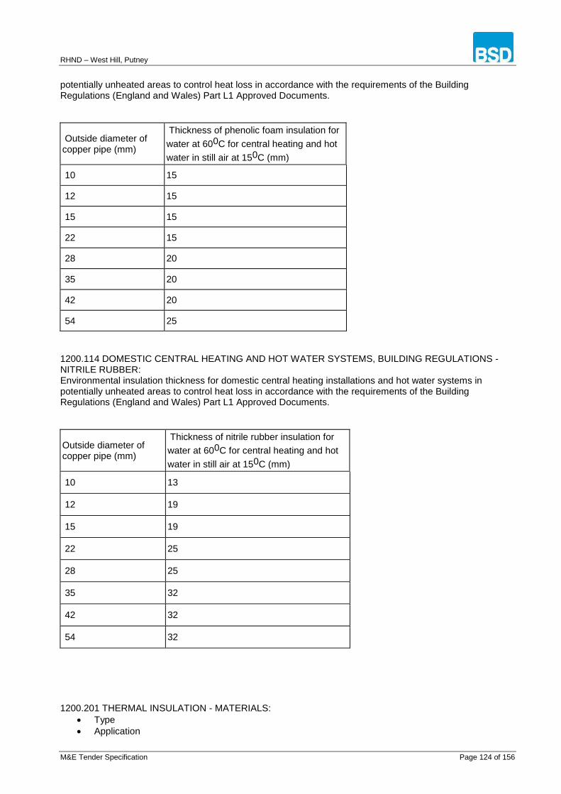
RHND – West Hill, Putney
M&E Tender Specification Page 124 of 156
potentially unheated areas to control heat loss in accordance with the requirements of the Building Regulations (England and Wales) Part L1 Approved Documents.
Outside diameter of copper pipe (mm)
Thickness of phenolic foam insulation for
water at 600C for central heating and hot
water in still air at 150C (mm)
10 15
12 15
15 15
22 15
28 20
35 20
42 20
54 25
1200.114 DOMESTIC CENTRAL HEATING AND HOT WATER SYSTEMS, BUILDING REGULATIONS - NITRILE RUBBER: Environmental insulation thickness for domestic central heating installations and hot water systems in potentially unheated areas to control heat loss in accordance with the requirements of the Building Regulations (England and Wales) Part L1 Approved Documents.
Outside diameter of copper pipe (mm)
Thickness of nitrile rubber insulation for
water at 600C for central heating and hot
water in still air at 150C (mm)
10 13
12 19
15 19
22 25
28 25
35 32
42 32
54 32
1200.201 THERMAL INSULATION - MATERIALS:
Type
Application

RHND – West Hill, Putney
M&E Tender Specification Page 125 of 156
Thermal Insulation Sub-contractor Standards
Comply in general with BS 5970. Description of terms as BS 3533. Thermal conductivity
Ensure values are in accordance with BS EN 12664, BS EN 12667, BS EN 12939 or BS EN ISO 8990. Fire rating
Employ materials that comply with BS 476-4, non-combustibility test, or obtain a Class 'O' fire rating to Building Regulations. When finished, comply with BS 476-7.
Class 1 spread of flame
Temperature of fluid in ducts (oC)
Material
Mineral fibre duct insulation
Rigid
Flexible
Lamella
Finish
Reinforced aluminium foil.
Adhesives.
Comply with the recommendations of clause 8.2 of BS 5970 section 2 for insulation bonding adhesives, lagging adhesives, facing and film attachment adhesives.
Protection
Application
Polyisobutylene
Minimum thickness 0.8mm.
Mild steel sheet continuously hot dipped with aluminium-zinc coating to BS EN 10327, applied directly to insulating material.
Finish
Flat sheet.
Ribbed sheet.
Aluminium sheeting
Apply flat (embossed) or profiled aluminium cladding directly to insulating material, thickness 0.71mm on ductwork.
Laminated foil/film
Reinforcement
Application
Aluminium bands at 300mm centres.
Aluminium bands at 450mm centres.
50mm x 19g galvanised wire netting to BS EN 10223.
50mm x 22g galvanised wire netting to BS EN 10223. 1200.202 THERMAL INSULATION WORKMANSHIP: Carry out thermal insulation work using one of the scheduled firms employing skilled craftsmen conversant with class of work. Do not apply thermal insulation until installation has been fully tested and all joints proved sound. Ensure all materials are kept dry. Insulate each unit separately. Do not enclose adjacent units together. Apply insulants, facings, coatings and protection strictly in accordance with manufacturer's instructions. Neatly finish joints, corners, edges and overlaps and, where possible, arrange overlaps to fall on blind side. Ensure overlaps are neat and even and parallel to circumferential and longitudinal joints.
RHND – West Hill, Putney
M&E Tender Specification Page 126 of 156
1300.000 TESTING AND COMMISSIONING 1300.101 PRESSURE TESTING: Advise appropriate personnel, at least 3 days in advance, of the time that pressure tests may be witnessed. Test concealed or buried pipework before any permanent covering is applied. Complete pressure testing before applying thermal insulation. Thoroughly flush out the whole system, fill system, vent all air from system and check for leaks, repair any leaks and re-check. Pressure test the system for a period of one hour, and check for and repair any leaks. Repeat pressure test if leaks have been found. Test at twice the working pressure. Test and purge gas pipelines in accordance with BS 6891 and IGE/UP/1A. 1300.102 STERILIZATION - GENERAL: After flushing process, carry out sterilization in accordance with BS 6700 and BS EN 806-4. Prior to sterilization ensure each system is flushed, cleaned and drained. Provide temporary connections to system terminal points suitable for introduction of sterilization chemicals and fluids and 22mm minimum valved drain connection on incoming main immediately downstream of mains isolating valve. Fill system with clean, fresh water. 1300.103 STERILIZATION - MAINS WATER SYSTEM: Carry out the following operations in accordance with BS 6700 and BS EN 806-4. Flush system and introduce sterilisation chemical, take samples to ensure correct chlorine concentration. Leave system to stand for Repeatedly flush system with clean water until all traces of chlorine have been removed - leave system filled. Submit samples to registered laboratory for microbiological analysis and report. 1300.104 STERILIZATION- WATER STORAGE SYSTEMS: Carry out the following operations in accordance with BS 6700, BS EN 806-4 and HSE L8 Approved Code of Practice and Guidance - Legionnaires' disease - control of legionella bacteria in water systems. Carry out procedures as for mains water systems on potable water storage tanks and cisterns, cold and hot. Certificate of conformity Immediately prior to handover, retake samples and submit for analysis and report. Where necessary repeat sterilisation of potable water systems immediately prior to handover. 1300.201 PRESSURE TESTING: Advise appropriate personnel, at least 3 days in advance, of the time that pressure tests may be witnessed. Test concealed or buried pipework before any permanent covering is applied. Complete pressure testing before applying thermal insulation. Isolate or remove pump and thoroughly flush out the whole system. Replace pump, fill system, vent all air from system and check for leaks, repair any leaks and re-check. Pressure test the system for a period of one hour, and check for and repair any leaks. Repeat pressure test if leaks have been found. Pressure test to twice the working pressure. Light boiler and run system to maximum temperature and check for leaks. Repair any leaks and repeat test. Add an approved corrosion inhibitor. Test and purge gas pipelines in accordance with BS 6891 and IGE/UP/1A. 1300.202 COMMISSIONING: Commission boiler in accordance with the procedures laid down by the boiler manufacturer. With boiler operating check and adjust all equipment and controls. Balance system to give approximately equal return temperatures from all heat emitters. Carry out commissioning of installations in accordance with the procedures, checks and tolerances given in the CIBSE Commissioning Codes and BSRIA Application Guides. 1300.301 COMMISSIONING REQUIREMENTS- DUCTWORK: Ensure and demonstrate that fans can provide specified duties.
RHND – West Hill, Putney
M&E Tender Specification Page 127 of 156
BS APPENDIX BS 1212-4:1991 Float operated valves. Part 4 Specification for compact type float operated valves for WC flushing cisterns (including floats). BS 1362:1973 Specification for general purpose fuse links for domestic and similar purposes (primarily for use in plugs) BS 1363-2:1995 13 A plugs, socket-outlets, adaptors and connection units. Part 2 Specification for 13 A switched and unswitched socket-outlets BS 1363-4:1995 13 A plugs, socket-outlets, adaptors and connection units. Part 4 Specification for 13A fused connection units switched and unswitched BS 143 and 1256:2000 Threaded pipe fittings in malleable cast iron and cast copper alloy BS 1566-2:1984 Copper indirect cylinders for domestic purposes. Part 2 Specification for single feed indirect cylinders BS 1710:1984 Specification for identification of pipelines and services BS 21:1985 Specification for pipe threads for tubes and fittings where pressure-tight joints are made on the threads (metric dimensions).
Partially superseded by BS EN 10226-1:2004 BS 2456:1990 Specification for floats (plastics) for float operated valves for cold water services BS 2879:1980 Specification for draining taps (screw-down pattern) BS 336:2010 Specification for fire hose couplings and ancillary equipment BS 3416:1991 Specification for bitumen-based coatings for cold application, suitable for use in contact with potable water BS 3456-202.46:1990 Specification for safety of household and similar electrical appliances. Particular requirements. Commercial electric steam cookers BS 3533:1981 Glossary of thermal insulation terms BS 3919:1987 Specification for technical tallow and animal grease BS 3924:1978 Specification for pressure-sensitive adhesive tapes for electrical insulating purposes. Current but partially replaced by Parts of BS EN 60454-3. Proposed for withdrawal, work in hand. BS 3958-4:1982 Thermal insulating materials. Part 4 Bonded preformed man-made mineral fibre pipe sections

RHND – West Hill, Putney
M&E Tender Specification Page 128 of 156
BS 416-1:1990 Discharge and ventilating pipes and fittings, sand-cast or spun in cast iron. Part 1 Specification for spigot and socket systems BS 417-2:1987 Specification for galvanized low carbon steel cisterns, cistern lids, tanks and cylinders. Part 2 Metric units BS 4177:1992 Specification for cooker control units BS 4235-1:1972 Specification for metric keys and keyways. Part 1 Parallel and taper keys BS 4293:1983 Specification for residual current-operated circuit breakers.
Partially replaced by BS EN 61008-1:1995 and BS IEC 1008-2-2:1990. BS 4500-4:1985 ISO limits and fits. Part 4 Specification for system of cone (taper) fits for cones from C=1:3 to 1:500, lengths from 6mm to 630mm and diameters up to 500mm BS 4500-5:1988 ISO limits and fits. Part 5 Specification for system of cone tolerances for conical workpieces from C=1:3 to 1:500 and lengths from 6mm to 630mm BS 4514:2001 Unplasticized PVC soil and ventilating pipes of 82.4mm minimum mean outside diameter, and fittings and accessories of 82.4mm and of other sizes. Specification BS 4533-102.1:1990 Luminaires. Particular requirements. Part 102.1 Specification for fixed general purpose luminaires BS 4573:1970 Specification for 2-pin reversible plugs and shaver socket-outlets BS 4579-2:1973 Specification for performance of mechanical and compression joints in electric cable and wire connectors. Part 2 Compression joints in nickel, iron and plated copper conductors BS 4662:2006+A1:2009 Boxes for flush mounting of electrical accessories. Requirements and test methods and dimensions BS 4678-4:1982 Cable trunking. Part 4 Specification for cable trunking made of insulating material. BS 4737-3.0:1988 Intruder alarm systems. Part 3.0 Specifications for components. General requirements BS 4737-3.1:1977 Intruder alarm systems. Part 3.1 Specifications for components. Continuous wiring BS 4737-3.10:1978 Intruder alarm systems. Part 3.10 Specifications for components. Vibration detectors BS 4737-3.12:1978 Intruder alarm systems. Part 3.12 Specifications for components. Beam interruption detectors BS 4737-3.13:1978 Intruder alarm systems. Part 3.13 Specifications for components. Capacitive proximity detectors BS 4737-3.14:1986

RHND – West Hill, Putney
M&E Tender Specification Page 129 of 156
Intruder alarm systems. Part 3.14 Specifications for components. Specification for deliberately operated devices BS 4737-3.2:1977 Intruder alarm systems. Part 3.2 Specifications for components. Foil on glass BS 4737-3.3:1977 Intruder alarm systems. Part 3.3 Specifications for components. Protective switches BS 4737-3.30:1986 Intruder alarm systems. Part 3.30 Specifications for components. Specification for PVC insulated cables for interconnecting wiring BS 4737-3.5:1978 Intruder alarm systems. Part 3.5 Specifications for components. Ultrasonic movement detectors BS 4737-3.6:1978 Intruder alarm systems. Part 3.6 Specifications for components. Acoustic detectors. BS 4737-3.8:1978 Intruder alarm systems. Part 3.8 Specifications for components. Volumetric capacitive detectors BS 4737-3.9:1978 Intruder alarms. Part 3.9 Specifications for components. Pressure mats BS 4737-5.2:1988 Intruder alarm systems. Part 5.2 Terms and symbols. Recommendations for symbols for diagrams BS 4856-1:1972 Methods for testing and rating fan coil units, unit heaters and unit coolers. Part 1 Thermal and volumetric performance for heating duties; without additional ducting BS 4856-2:1975 Methods for testing and rating fan coil units, unit heaters and unit coolers. Part 2 Thermal and volumetric performance for cooling duties; without additional ducting BS 4856-3:1975 Methods for testing and rating fan coil units, unit heaters and unit coolers. Part 3 Thermal and volumetric performance for heating and cooling duties; with additional ducting BS 5154:1991 Specification for copper alloy globe, globe stop and check, check and gate valves.
Partially replaced by BS EN 12288:2003 BS 5255:1989 Specification for thermoplastics waste pipe and fittings. Partially replaced by BS EN 1329-1:2000, BS EN 1451-1:2000, BS EN 1566-1:2000 but remains current BS 5306-1:2006 Code of practice for fire extinguishing installations and equipment on premises. Part 1 Hose reels and foam inlets BS 5422:2009 Method for specifying thermal insulating materials for pipes, tanks, vessels, ductwork and equipment operating within the temperature range -40 degree C to +700degree C BS 5446-3:2005 Fire detection and fire alarm devices for dwellings. Part 3 Specification for smoke alarm kits for deaf and hard of hearing people BS 546:1950

RHND – West Hill, Putney
M&E Tender Specification Page 130 of 156
Specification. Two-pole and earthing-pin plugs, socket-outlets and socket-outlet adaptors. If required, see also Supplement No 1:1960 Specification for plugs made of resilient material BS 5467:1997+A3:2008 Electric cables. Thermosetting insulated, armoured cables for voltages of 600/1000 V and 1900/3300 V BS 5588-1:1990 Fire precautions in the design, construction and use of buildings. Part 1 Code of practice for residential buildings BS 5615:1985 Specification for insulating jackets for domestic hot water storage cylinders BS 5627:1984 Specification for plastics connectors for use with horizontal outlet vitreous china WC pans BS 5640-1:1978 Aerials for the reception of sound and television broadcasting in the frequency range 30 MHz to 1 GHz. Part 1 Specification for electrical and mechanical characteristics BS 5640-2:1978 Aerials for the reception of sound and television broadcasting in the frequency range 30 MHz to 1 GHz. Part 2 Methods of measurement of electrical performance parameters BS 5733:2010 General requirements for electrical accessories. Specification BS 5839-1:2002+A2:2008 Fire detection and alarm systems for buildings. Part 1 Code of practice for system design, installation, commissioning and maintenance BS 5839-3:1988 Fire detection and alarm systems for buildings. Part 3 Specification for automatic release mechanisms for certain fire protection equipment BS 5839-6:2004 Fire detection and alarm systems for buildings. Part 6 Code of practice for the design, installation and maintenance of fire detection and fire alarm systems in dwellings BS 5839-8:2008 Fire detection and alarm systems for buildings. Part 8 Code of practice for the design, installation, commissioning and maintenance of voice alarm systems BS 5839-9:2011 Fire detection and fire alarm systems for buildings. Part 9 Code of practice for the design, installation, commissioning and maintenance of emergency voice communication systems BS 5955-8:2001 Plastics pipework (thermoplastics materials). Part 8 Specification for the installation of thermoplastic pipes and associated fittings for use in domestic hot and cold services and heating systems in buildings BS 5970:2001 Code of practice for thermal insulation of pipework and equipment in the temperature range of -100°C to +870°C BS 6004:2000 Electric cables. PVC insulated, non-armoured cables for voltages up to and including 450/750 V, for electric power, lighting and internal wiring BS 6144:1990 Specification for expansion vessels using an internal diaphragm, for unvented hot water supply systems

RHND – West Hill, Putney
M&E Tender Specification Page 131 of 156
BS 6150:2006 Painting of buildings. Code of practice BS 6351-3:1983 Electric surface heating. Part 3 Code of practice for the installation, testing and maintenance of electric surface heating systems BS 65:1991 Specification for vitrified clay pipes, fittings and ducts, also flexible mechanical joints for use solely with surface water pipes and fittings BS 6500:2000 Electric cables. Flexible cords rated up to 300/500 V, for use with appliances and equipment intended for domestic, office and similar environments BS 67:1987 Specification for ceiling roses BS 6700:2006+A1:2009 Design, installation, testing and maintenance of services supplying water for domestic use within buildings and their curtilages. Specification
Partially superseded by BS EN 806-4:2010 BS 6701:2010 Telecommunications equipment and telecommunications cabling. Specification for installation, operation and maintenance BS 6724:1997+A3:2008 Electric cables. Thermosetting insulated, armoured cables for voltages of 600/1000 V and 1900/3300 V, having low emission of smoke and corrosive gases when affected by fire BS 7074-1:1989 Application, selection and installation of expansion vessels and ancillary equipment for sealed water systems. Part 1 Code of practice for domestic heating and hot water supply BS 7074-2:1989 Application, selection and installation of expansion vessels and ancillary equipment for sealed water systems. Part 2 Code of practice for low and medium temperature hot water heating systems BS 7181:1989 Specification for storage cisterns up to 500 L actual capacity for water supply for domestic purposes BS 7211:1998 Electric cables. Thermosetting insulated, non-armoured cables for voltages up to and including 450/750 V, for electric power, lighting and internal wiring, and having low emission of smoke and corrosive gases when affected by fire BS 7291-1:2010 Thermoplastics pipes and fitting systems for hot and cold water for domestic purposes and heating installations in buildings. Part 1 General requirements BS 7291-2:2010 Thermoplastics pipes and associated fittings for hot and cold water for domestic purposes and heating installations in buildings. Part 2 Specification for polybutylene (PB) pipes and associated fittings BS 7291-3:2010 Thermoplastics pipes and associated fittings for hot and cold water for domestic purposes and heating installations in buildings. Part 3 Specification for cross-linked polyethylene (PE-X) pipes and associated fittings
RHND – West Hill, Putney
M&E Tender Specification Page 132 of 156
BS 7291-4:1990 Thermoplastics pipes and associated fittings for hot and cold water for domestic purposes and heating installations in buildings. Part 4 Specification for chlorinated polyvinyl chloride (PVC-C) pipes and associated fittings and solvent cement Current, Obsolescent BS 7430:1998 Code of practice for earthing BS 7587:1992 Specification for interconnection of radio and TV receivers to feeder system outlets BS 7649:1993 Guide to the design and preparation of documentation for users of application software BS 7654:1997 Specification for single phase street lighting fuses (cut-outs) for low-voltage public electricity distribution systems. 25 A rating for highway power supplies and street furniture BS 7671:2008 Requirements for electrical installations. IEE Wiring Regulations. Seventeenth edition BS 7697:1993 Nominal voltages for low voltage public electricity supply systems BS 7786:2006 Specification for unsintered PTFE tapes for general use. BS 7838:1996 Specification for corrugated stainless steel semi-rigid pipe and associated fittings for low-pressure gas pipework of up to 28 mm
Replaced by BS EN 15266:2007 but remains current BS 7854-1:1996 Mechanical vibration. Evaluation of machine vibration by measurements on non-rotating parts. Part 1 General guidelines BS 7895:1997 Specification for bayonet lampholders with enhanced safety BS 7919:2001 Electric cables. Flexible cables rated up to 450/750V, for use with appliances and equipment intended for industrial and similar environments BS 7942:2011 Thermostatic mixing valves for use in care establishments. Requirements and test methods BS 8000-13:1989 Workmanship on building sites. Part 13 Code of practice for above ground drainage and sanitary appliances BS 848-1:2007 Fans for general purposes. Part 1 Performance testing using standardized airways BS 848-4:1997 Fans for general purposes. Part 4 Dimensions BS 848-7:2003 Fans for general purposes. Part 7 Specifications for balancing and vibration. BS 8521:2009 Specification for dual-tone multi-frequency (DTMF) signalling protocol for social alarm systems

RHND – West Hill, Putney
M&E Tender Specification Page 133 of 156
BS 864-5:1990 Capillary and compression tube fittings of copper and copper alloy. Part 5 Specification for compression fittings for polyethylene pipes with outside diameters to BS 5556. Obsolescent.Replaced by BS EN 1254-3:1998 but remains current. BS 88-2:2010 Supplementary requirements for fuses for use by authorized persons (fuses mainly for industrial application). Examples of standardized systems of fuses A to I BS 88-3:2010 Supplementary requirements for fuses for use by unskilled persons (fuses mainly for household or similar applications). Examples of standardized systems of fuses A toF. BS 9999:2008 Code of practice for fire safety in the design, management and use of buildings BS EN 10143:2006 Continuously hot-dip metal coated steel sheet and strip. Tolerances on dimensions and shape BS EN 10223-2:1998 Steel wire and wire products for fences. Part 2 Hexagonal steel wire netting for agricultural, insulation and fencing purposes BS EN 10226-1:2004 Pipe threads where pressure tight joints are made on the threads. Part 1 Taper external threads and parallel internal threads. Dimensions, tolerances and designation BS EN 10242:1995 Threaded pipe fittings in malleable cast iron BS EN 10255:2004 Non-alloy steel tubes suitable for welding or threading. Technical delivery conditions BS EN 10326:2004 Continuously hot-dip coated strip and sheet of structural steels. Technical delivery conditions BS EN 10327:2004 Continuously hot-dip coated strip and sheet of low carbon steels for cold forming. Technical delivery conditions BS EN 1057:2006+A1:2010 Copper and copper alloys. Seamless, round copper tubes for water and gas in sanitary and heating applications BS EN 1111:1999 Sanitary tapware. Thermostatic mixing valves (PN 10). General technical specification BS EN 12056-1:2000 Gravity drainage systems inside buildings. Part 1 General and performance requirements BS EN 12056-2:2000 Gravity drainage systems inside buildings. Part 2 Sanitary pipework, layout and calculation BS EN 12056-3:2000 Gravity drainage systems inside buildings. Part 3 Roof drainage, layout and calculation BS EN 12056-4:2000 Gravity drainage systems inside buildings. Part 4 Wastewater lifting plants. Layout and calculation BS EN 12201-1:2003

RHND – West Hill, Putney
M&E Tender Specification Page 134 of 156
Plastic piping systems for water supply. Polyethylene (PE). Part 1 General BS EN 12201-2:2003 Plastic piping systems for water supply. Polyethylene (PE). Part 2 Pipes BS EN 12201-5:2003 Plastic piping systems for water supply. Polyethylene (PE). Part 5 Fitness for purpose of the system BS EN 12288:2010 Industrial valves. Copper alloy gate valves. BS EN 12449:1999 Copper and copper alloys. Seamless, round tubes for general purposes BS EN 12450:1999 Copper and copper alloys. Seamless, round copper capillary tubes BS EN 1254-1:1998 Copper and copper alloys. Plumbing fittings. Part 1 Fittings with ends for capillary soldering or capillary brazing to copper tubes. BS EN 1254-2:1998 Copper and copper alloys. Plumbing fittings. Part 2 Fittings with compression ends for use with copper tubes BS EN 1254-3:1998 Copper and copper alloys. Plumbing fittings. Part 3 Fittings with compression ends for use with plastics pipes BS EN 12664:2001 Thermal performance of building materials and products. Determination of thermal resistance by means of guarded hot plate and heat flow meter methods. Dry and moist products of medium and low thermal resistance BS EN 12667:2001 Thermal performance of building materials and products. Determination of thermal resistance by means of guarded hot plate and heat flow meter methods - Products of high and medium thermal resistance BS EN 12693:2008 Refrigerating systems and heat pumps. Safety and environmental requirements. Positive displacement refrigerant compressors BS EN 12831:2003 Heating systems in buildings. Method for calculation of the design heat load BS EN 1286:1999 Sanitary tapware. Low pressure mechanical mixing valves. General technical specification BS EN 1287:1999 Sanitary tapware. Low pressure thermostatic mixing valves. General technical specifications BS EN 12897:2006 Water supply. Specification for indirectly heated unvented (closed) storage water heaters BS EN 13032-1:2004 Light and lighting. Measurement and presentation of photometric data of lamps and luminaires. Part 1 Measurement and file format BS EN 13141-1:2004 Ventilation for buildings. Performance testing of components/products for residential ventilation. Part 1 Externally and internally mounted air transfer devices BS EN 13141-2:2010

RHND – West Hill, Putney
M&E Tender Specification Page 135 of 156
Ventilation for buildings. Performance testing of components/products for residential ventilation. Part 2 Exhaust and supply air terminal devices BS EN 13141-3:2004 Ventilation for buildings. Performance testing of components/products for residential ventilation. Part 3 Range hoods for residential use BS EN 13141-4:2004 Ventilation for buildings. Performance testing of components/products for residential ventilation. Part 4 Fans used in residential ventilation systems BS EN 13141-5:2004 Ventilation for buildings. Performance testing of components/products for residential ventilation. Part 5 Cowls and roof outlet terminal devices BS EN 13141-6:2004 Ventilation for buildings. Performance testing of components/products for residential ventilation. Part 6 Exhaust ventilation system packages used in a single dwelling BS EN 13141-7:2010 Ventilation for buildings. Performance testing of components/products for residential ventilation. Part 7 Performance testing of a mechanical supply and exhaust ventilation units (including heat recovery) for mechanical ventilation systems intended for single family dwellings BS EN 13141-8:2006 Ventilation for buildings. Performance testing of components/products for residential ventilation. Part 8 Performance testing of un-ducted mechanical supply and exhaust ventilation units (including heat recovery) for mechanical ventilation systems intended for a single room BS EN 13142:2004 Ventilation for buildings. Components/products for residential ventilation. Required and optional performance characteristics BS EN 13166:2008 Thermal insulation products for buildings. Factory made products of phenolic foam (PF). Specification BS EN 1329-1:2000 Plastics piping systems for soil and waste discharge (low and high temperature) within the building structure. Unplasticized poly(vinyl chloride) (PVC-U). Specifications for pipes, fittings and the system BS EN 13831:2007 Closed expansion vessels with built-in diaphragm for installation in water BS EN 14337:2005 Heating systems in buildings. Design and installation of direct electrical room heating systems BS EN 14604:2005 Smoke alarm devices BS EN 1462:2004 Brackets for eaves gutters. Requirements and testing BS EN 14829:2007 Independent gas-fired flueless space heaters for nominal heat input not exceeding 6kW BS EN 1555-1:2010 Plastics piping systems for the supply of gaseous fuels. Polyethylene (PE). Part 1 General BS EN 1555-2:2010 Plastics piping systems for the supply of gaseous fuels. Polyethylene (PE). Part 2 Pipes.

RHND – West Hill, Putney
M&E Tender Specification Page 136 of 156
BS EN 1555-3:2010 Plastics piping systems for the supply of gaseous fuels. Polyethylene (PE). Part 3 Fittings. BS EN 1555-5:2010 Plastics piping systems for the supply of gaseous fuels. Polyethylene (PE). Part 5 Fitness for purpose of the system. BS EN 15665:2009 Ventilation for buildings. Determining performance criteria for residential ventilation systems BS EN 16147:2011 Heat pumps with electrically driven compressors. Testing and requirements for marking of domestic hot water units BS EN 215:2004 Thermostatic radiator valves. Requirements and test methods BS EN 274-1:2002 Waste fittings for sanitary appliances. Part 1 Requirements BS EN 274-2:2002 Waste fittings for sanitary appliances. Part 2 Test methods BS EN 274-3:2002 Waste fittings for sanitary appliances. Part 3 Quality control BS EN 33:2003 Pedestal W.C. pans with close-coupled flushing cistern. Connecting dimensions BS EN 37:1999 Pedestal W.C. pans with independent water supply. Connecting dimensions BS EN 378-1:2008+A1:2010 Refrigerating systems and heat pumps. Safety and environmental requirements. Part 1 Basic requirements, definitions, classification and selection criteria BS EN 378-2:2008+A1:2009 Refrigerating systems and heat pumps. Safety and environmental requirements. Part 2 Design, construction, testing, marking and documentation BS EN 378-3:2008 Refrigerating systems and heat pumps. Safety and environmental requirements. Part 3 Installation site and personal protection BS EN 378-4:2008 Refrigerating systems and heat pumps. Safety and environmental requirements. Part 4 Operation, maintenance, repair and recovery BS EN 41003:2009 Particular safety requirements for equipment to be connected to telecommunications networks BS EN 50065-1:2001+A1:2010 Signalling on low-voltage electrical installations in the frequency range 3 kHz to 148.5 kHz. Part 1 General requirements, frequency bands and electromagnetic disturbances BS EN 50083-2:2006 Cabled distribution systems for television and sound signals. Part 2 Electromagnetic compatibility for equipment BS EN 50083-7:1997 Cable networks for television signals, sound signals and interactive services. Part 7 System performance

RHND – West Hill, Putney
M&E Tender Specification Page 137 of 156
BS EN 50083-8:2002+A11:2008 Cabled distribution systems for television and sound signals. Part 8 Electromagnetic compatibility for networks BS EN 50083-9:2002 Cabled distribution systems for television and sound signals. Part 9 Interfaces for CATV/SMATV headends and similar professional equipment for DVB/MPEG-2 transport streams BS EN 50085-1:2005 Cable trunking systems and cable ducting systems for electrical installations. Part 1 General requirements BS EN 50085-2-1:2006 Cable trunking systems and cable ducting systems for electrical installations. Part 2-1 Cable trunking systems and cable ducting systems intended for mounting on walls and ceilings BS EN 50117-1:2002 Coaxial cables. Part 1 Generic specification BS EN 50131-1:2006 Alarm systems. Intrusion and hold-up systems. Part 1 System requirements BS EN 50131-6:2008 Alarm systems. Intrusion and hold-up systems. Part 6 Power supplies BS EN 50134-1:2002 Alarm systems. Social alarm systems. Part 1 System requirements BS EN 50134-2:2000 Alarm systems. Social alarm systems. Part 2 Trigger devices BS EN 50134-3:2001 Alarm systems. Social alarm systems. Part 3 Local unit and controller BS EN 50174-1:2001 Information technology. Cabling installation. Part 1 Specification and quality assurance BS EN 50174-2:2001 Information technology. Cabling installation. Part 2 Installation planning and practices inside buildings BS EN 50174-3:2003 Information technology. Cabling installation. Part 3 Installation planning and practices outside buildings BS EN 50262:1999 Metric cable glands for electrical installations BS EN 50290-2-22:2002 Communication cables. Part 2-22 Common design rules and construction. PVC sheathing compounds BS EN 50290-2-27:2002 Communication cables. Part 2-27 Common design rules and construction. Halogen free flame retardant thermoplastic sheathing compounds BS EN 50292:2002 Electrical apparatus for the detection of carbon monoxide in domestic premises. Guide on the selection, installation, use and maintenance BS EN 50428:2005+A2:2009 Switches for household and similar fixed electrical installations. Collateral standard. Switches and related accessories for use in home and building electronic systems (HBES)
RHND – West Hill, Putney
M&E Tender Specification Page 138 of 156
BS EN 50441-1:2006 Cables for indoor residential telecommunication installations. Part 1 Unscreened cables. Grade 1 BS EN 50441-2:2006 Cables for indoor residential telecommunication installations. Part 2 Screened cables. Grade 2 BS EN 50441-3:2006 Cables for indoor residential telecommunication installations. Part 3 Screened cables. Grade 3 BS EN 54-11:2001 Fire detection and fire alarm systems. Part 11 Manual call points BS EN 54-13:2005 Fire detection and fire alarm systems. Part 13 Compatibility assessment of system components BS EN 54-17:2005 Fire detection and fire alarm systems. Part 17 Short-circuit isolators BS EN 54-18:2005 Fire detection and fire alarm systems. Part 18 Input/output devices BS EN 54-2:1997+A1:2006 Fire detection and fire alarm systems. Part 2 Control and indicating equipment BS EN 54-21:2006 Fire detection and fire alarm systems. Part 21 Alarm transmission and fault warning routing equipment BS EN 54-3:2001 Fire detection and fire alarm systems. Part 3 Fire alarm devices. Sounders BS EN 54-4:1998 Fire detection and fire alarm systems. Part 4 Power supply equipment BS EN 54-5:2001 Fire detection and fire alarm systems. Part 5 Heat detectors. Point detectors BS EN 54-7:2001 Fire detection and fire alarm systems. Part 7 Smoke detectors. Point detectors using scattered light, transmitted light or ionization BS EN 55011:2007 Industrial, scientific and medical (ISM) radio-frequency equipment. Electromagnetic disturbance characteristics. Limits and methods of measurement BS EN 55013:2001 Sound and television broadcast receivers and associated equipment. Radio disturbance characteristics. Limits and methods of measurement BS EN 55014-1:2006+A1:2009 Electromagnetic compatibility. Requirements for household appliances, electric tools and similar apparatus. Part 1 Emission BS EN 55014-2:1997+A2:2008 Electromagnetic compatibility. Requirements for household appliances, electric tools and similar apparatus. Immunity. Part 2 Product family standard BS EN 55015:2006+A2:2009 Limits and methods of measurement of radio disturbance characteristics of electrical lighting and similar equipment BS EN 55020:2007 Sound and television broadcast receivers and associated equipment. Immunity characteristics. Limits and

RHND – West Hill, Putney
M&E Tender Specification Page 139 of 156
methods of measurement BS EN 55022:2006+A1:2007 Information technology equipment. Radio disturbance characteristics. Limits and methods of measurement BS EN 60064:1995+A4:2007 Tungsten filament lamps for domestic and similar general lighting purposes. Performance requirements BS EN 60081:1998 Double-capped fluorescent lamps. Performance specifications BS EN 60188:2001 High-pressure mercury vapour lamps. Performance specifications BS EN 60192:2001 Low pressure sodium vapour lamps. Performance specification BS EN 60238:2004+A1:2009 Edison screw lampholders BS EN 60240-1:1994 Characteristics of electric infra-red emitters for industrial heating. Part 1 Short wave infra-red emitters BS EN 60269-1:2007+A1:2009 Low-voltage fuses. Part 1 General requirements BS EN 60269-4:2009 Low-voltage fuses. Part 4 Supplementary requirements for fuse-links for the protection of semiconductor devices BS EN 60335-1:2002+A14:2010 Household and similar electrical appliances. Safety. Part 1 General requirements. BS EN 60335-2-21:2003+A2:2008 Specification for safety of household and similar electrical appliances. Part 2-21 Particular requirements. Particular requirements for storage water heaters BS EN 60335-2-23:2003+A11:2010 Specification for safety of household and similar electrical appliances. Part 2-23 Particular requirements for appliances for skin or hair care BS EN 60335-2-30:2009 Household and similar electrical appliances. Part 2-30 Particular requirements for room heaters BS EN 60335-2-35:2002 Specification for safety of household and similar electrical appliances. Part 2-35 Particular requirements. Particular requirements for instantaneous water heaters BS EN 60335-2-40:2003+A2:2009 Specification for safety of household and similar electrical appliances. Part 2-40 Particular requirements for electrical heat pumps, air-conditioners and dehumidifiers BS EN 60335-2-43:2003+A2:2008 Specification for safety of household and similar electrical appliances. Part 2-43 Particular requirements for clothes dryers and towel rails BS EN 60335-2-61:2003+A2:2008 Specification for safety of household and similar electrical appliances. Part 2-61 Particular requirements for thermal-storage room heater BS EN 60335-2-73:2003+A2:2009 Household and similar electrical appliances. Safety Part 2-73 Particular requirements for fixed immersion

RHND – West Hill, Putney
M&E Tender Specification Page 140 of 156
heaters BS EN 60335-2-80:2003+A2:2009 Specification for safety of household and similar electrical appliances. Part 2-80 Particular requirements for fans BS EN 60335-2-88:2002 Specification for safety of household and similar electrical appliances. Part 2-88 Particular requirements. Particular requirements for humidifiers intended for use with heating, ventilation, or air-conditioning systems BS EN 60335-2-98:2003+A2:2008 Specification for safety of household and similar electrical appliances. Part 2-98 Particular requirements for humidifiers BS EN 60400:2008 Lampholders for tubular fluorescent lamps and starterholders BS EN 60432-1:2000 Safety specification for incandescent lamps. Part 1 Tungsten filament lamps for domestic and similar general lighting purposes BS EN 60432-2:2000 Safety specification for incandescent lamps. Part 2 Tungsten halogen lamps for domestic and similar general lighting purposes BS EN 60439-3:1991+A2:2001 Specification for low-voltage switchgear and controlgear assemblies. Part 3 Particular requirements for low-voltage switchgear and controlgear assemblies intended to be installed in places where unskilled persons have access to their use. Distribution boards BS EN 60454-1:1995 Specifications for pressure-sensitive adhesive tapes for electrical purposes. Part 1 General requirements BS EN 60529:1992 Specification for degrees of protection provided by enclosures (IP code) BS EN 60598-1:2008 Luminaires. Part 1 General requirements and tests BS EN 60598-2-2:1997 Luminaires. Part 2-2 Particular requirements. Recessed luminaires BS EN 60598-2-22:1998+A2:2008 Luminaires. Part 2-22. Particular requirements. Luminaires for emergency lighting BS EN 60669-1:2000+A2:2008 Switches for household and similar fixed electrical installations. Part 1 General requirements BS EN 60669-2-4:2005 Switches for household and similar fixed electrical installations. Part 2-4 Particular requirements. Isolating switches BS EN 60670-23:2008 Boxes and enclosures for electrical accessories for household and similar fixed electrical installations. Part 23 Particular requirements for floor boxes and enclosures BS EN 60702-1:2002 Mineral insulated cables and their terminations with a rated voltage not exceeding 750 V. Part 1 Cables BS EN 60702-2:2002 Mineral insulated cables and their terminations with a rated voltage not exceeding 750 V. Part 2

RHND – West Hill, Putney
M&E Tender Specification Page 141 of 156
Terminations BS EN 60728-1:2008 Cable networks for television signals, sound signals and interactive services. Part 1 System performance of forward paths BS EN 60728-11:2005 Cable networks for television signals, sound signals and interactive services. Part 11 Safety BS EN 60728-4:2008 Cable networks for television signals, sound signals and interactive services. Part 4 Passive wideband equipment for coaxial cable networks BS EN 60728-5:2008 Cable networks for television signals and interactive services. Part 5 Headend equipment BS EN 60730-1:2001+A2:2008 Specification for automatic electrical controls for household and similar use. Part 1 General requirements BS EN 60730-2-13:2008 Specification for automatic electrical controls for household and similar use. Particular requirements. Part 2-13 Particular requirements for humidity sensing controls BS EN 60730-2-3:2007 Specification for automatic electrical controls for household and similar use. Part 2-3 Particular requirements. Thermal protectors for ballasts for tubular fluorescent lamps BS EN 60730-2-5:2002+A2:2010 Specification for automatic electrical controls for household and similar use. Part 2-5 Particular requirements. Particular requirements for automatic electrical burner control systems BS EN 60730-2-7:1992 Specification for automatic electrical controls for household and similar use. Part 2-7 Particular requirements. Timers and time switches BS EN 60730-2-9:2010 Automatic electrical controls for household and similar use. Part 2-9 Particular requirements for temperature sensing controls BS EN 60801-2:1993 Electromagnetic compatibility for industrial-process measurement and control equipment. Part 2 Electrostatic discharge requirements BS EN 60898-1:2003+A1:2004 Circuit-breakers for overcurrent protection for household and similar installations. Part 1 Circuit-breakers for a.c. operation BS EN 60921:2004 Ballasts for tubular fluorescent lamps. Performance requirements BS EN 60923:2005 Auxiliaries for lamps. Ballasts for discharge lamps (excluding tubular fluorescent lamps). Performance requirements BS EN 60925:1991 Specification for performance requirements for d.c. supplied electronic ballasts for tubular fluorescent lamps BS EN 60927:2007 Auxiliaries for lamps. Starting devices (other than glow starters). Performance requirements BS EN 60929:2006
RHND – West Hill, Putney
M&E Tender Specification Page 142 of 156
A.C. supplied electronic ballasts for tubular fluorescent lamps. Performance requirements BS EN 60998-2-4:2005 Connecting devices for low voltage circuits for household and similar purposes. Part 2-4 Particular requirements for twist-on connecting devices BS EN 61000-6-1:2007 Electromagnetic compatibility (EMC). Generic standards. Part 6-1 Immunity for residential, commercial and light-industrial environments BS EN 61000-6-2:2005 Electromagnetic compatibility (EMC). Generic standards. Part 6-2 Immunity for industrial environments BS EN 61000-6-3:2007 Electromagnetic compatibility (EMC). Generic standards. Part 6-3 Emission standard for residential, commercial and light-industrial environments BS EN 61000-6-4:2007 Electromagnetic compatibility (EMC). Generic standards. Part 6-4 Emission standard for industrial environments BS EN 61008-1:2004+A12:2009 Residual current operated circuit-breakers without integral overcurrent protection for household and similar uses (RCCBs). Part 1 General rules BS EN 61009-1:2004 Residual current operated circuit-breakers with integral overcurrent protection for household and similar uses (RCBO's). Part 1 General rules BS EN 61009-2-1:1995 Specification for residual current operated circuit-breakers with integral overcurrent protection for household and similar uses (RCBOs). Part 2-1 Applicability of the general rules to RCBOs functionally independent of line voltage BS EN 61048:2006 Auxiliaries for lamps. Capacitors for use in tubular fluorescent and other discharge lamp circuits. General and safety requirements BS EN 61049:1993 Specification for capacitors for use in tubular fluorescent and other discharge lamp circuits. Performance requirements BS EN 61082-1:2006 Preparation of documents used in electrotechnology. Part 1 Rules BS EN 61184:1997 Bayonet lampholders BS EN 61238-1:2003 Compression and mechanical connectors for power cables for rated voltages up to 36 kV (Um = 42 kV). Part 1 Test methods and requirements BS EN 61347-2-1:2001 Lamp controlgear. Part 2-1 Particular requirements for starting devices (other than glow starters) BS EN 61347-2-13:2006 Lamp controlgear. Part 2-13 Particular requirements for d.c. or a.c. supplied electronic controlgear for LED modules BS EN 61347-2-3:2001 Lamp controlgear. Part 2-3 Particular requirements for a.c. supplied electronic ballasts for fluorescent lamps

RHND – West Hill, Putney
M&E Tender Specification Page 143 of 156
BS EN 61347-2-4:2001 Lamp controlgear. Part 2-4 Particular requirements for d.c. supplied electronic ballasts for general lighting BS EN 61347-2-5:2001 Lamp controlgear. Part 2-5 Particular requirements for d.c. supplied electronic ballasts for public transport lighting BS EN 61347-2-6:2001 Lamp controlgear. Part 2-6 Particular requirements for d.c. supplied electronic ballasts for aircraft lighting BS EN 61347-2-7:2006 Lamp controlgear. Part 2-7 Particular requirements for D.C. supplied electronic ballasts for emergency lighting BS EN 61347-2-8:2001 Lamp controlgear. Part 2-8 Particular requirements for ballasts for fluorescent lamps BS EN 61347-2-9:2001 Lamp controlgear. Part 2-9 Particular requirements for ballasts for discharge lamps (excluding fluorescent lamps) BS EN 61386-21:2004 Conduit systems for cable management. Part 21 Particular requirements. Rigid conduit systems BS EN 61537:2007 Cable management. Cable tray systems and cable ladder systems BS EN 62031:2008 LED modules for general lighting. Safety specifications BS EN 62035:2000 Discharge lamps (excluding fluorescent lamps). Safety specifications BS EN 62080:2009 Sound signalling devices for household and similar purposes BS EN 62301:2008 LED modules for general lighting. Safety specifications BS EN 625:1996 Gas-fired central heating boilers. Specific requirements for the domestic hot water operation of combination boilers of nominal heat input not exceeding 70 kW BS EN 671-1:2001 Fixed fire fighting systems. Hose systems. Part 1 Hose reels with semi-rigid hose BS EN 671-3:2009 Fixed fire fighting systems. Hose systems. Part 3 Maintenance of hose reels with semi-rigid hose and hose systems with lay-flat hose BS EN 681-1:1996 Elastomeric seals. Material requirements for pipe joint seals used in water and drainage applications. Part 1 Vulcanized rubber BS EN 681-2:2000 Elastomeric seals. Material requirements for pipe joint seals used in water and drainage applications. Thermoplastic elastomers BS EN 751-2:1997 Sealing materials for metallic threaded joints in contact with 1st, 2nd and 3rd family gases and hot water. Part 2 Non-hardening jointing compounds BS EN 806-1:2000
RHND – West Hill, Putney
M&E Tender Specification Page 144 of 156
Specifications for installations inside buildings conveying water for human consumption. Part 1 General BS EN 806-2:2005 Specifications for installations inside buildings conveying water for human consumption. Part 2 Design BS EN 806-3:2006 Specifications for installations inside buildings conveying water for human consumption. Part 3 Pipe sizing. Simplified method BS EN 806-4:2010 Specifications for installations inside buildings conveying water for human consumption. Part 4 Installation BS EN 877:1999+A1:2006 Cast iron pipes and fittings, their joints and accessories for the evacuation of water from buildings. Requirements, test methods and quality assurance BS EN 997:2003 WC pans and WC suites with integral trap BS EN ISO 12241:2008 Thermal insulation for building equipment and industrial installations. Calculation rules BS EN ISO 13567-1:2002 Technical product documentation. Organization and naming of layers for CAD. Part 1 Overview and principles BS EN ISO 13567-2:2002 Technical product documentation. Organization and naming of layers for CAD. Part 2 Concepts, format and codes used in construction documentation BS EN ISO 1452-1:2009 Plastics piping systems for water supply and for buried and above-ground drainage and sewerage under pressure. Unplasticized poly(vinyl chloride) (PVC U). Part 1 General BS EN ISO 1452-2:2009 Plastics piping systems for water supply and for buried and above-ground drainage and sewerage under pressure. Unplasticized poly(vinyl chloride) (PVC U). Part 2 Pipes BS EN ISO 1452-3:2009 Plastics piping systems for water supply and for buried and above-ground drainage and sewerage under pressure. Unplasticized poly(vinyl chloride) (PVC U). Part 3 Fittings BS EN ISO 1452-4:2009 Plastics piping systems for water supply and for buried and above-ground drainage and sewerage under pressure. Unplasticized poly(vinyl chloride) (PVC U). Part 4 Valves BS EN ISO 1452-5:2009 Plastics piping systems for water supply and for buried and above-ground drainage and sewerage under pressure. Unplasticized poly(vinyl chloride) (PVC U). Part 5 Fitness for purpose of the system BS EN ISO 4126-1:2004 Safety devices for protection against excessive pressure. Part 1 Safety valves BS EN ISO 5136:2003 Acoustics. Determination of sound power radiated into a duct by fans and other air-moving devices. In-duct method BS EN ISO 8990:1996 Thermal insulation. Determination of steady-state thermal transmission properties. Calibrated and guarded hot box

RHND – West Hill, Putney
M&E Tender Specification Page 145 of 156
BS EN ISO 9001:2008 Quality management systems. Requirements BS EN ISO 9453:2006 Soft solder alloys. Chemical compositions and forms BS IEC 1008-2-2:1990 Specification for residual current operated circuit-breakers with integral overcurrent protection for household and similar uses (RCCBs). Applicability of the general rules to RCCBs functionally dependent on line voltage BS ISO 11342:1998 Mechanical vibration. Methods and criteria for the mechanical balancing of flexible rotors BS ISO 14695:2003 Fans for general purposes. Method of measurement of fan vibration BS ISO 1940-1:2003 Mechanical vibration. Balance quality requirements for rotors in a constant (rigid) state. Part 1 Specification and verification of balance tolerances BS ISO 5011:2000 Inlet air cleaning equipment for internal combustion engines and compressors. Performance testing BS ISO 7240-8:2007 Fire detection and alarm systems. Part 8 Carbon monoxide fire detectors using an electro-chemical cell in combination with a heat sensor.

RHND – West Hill, Putney
M&E Tender Specification Page 146 of 156
APPENDIX A - O&M REQUIREMENTS
1.0 Introduction
The purpose of operating and maintenance manuals is to provide information which will alert those who are responsible for the installation after handover, of the key health and safety risks that will need to be dealt with during subsequent construction work, including maintenance, cleaning, repair, alteration, refurbishment and demolition.
The provision of Operating and Maintenance manuals that form part of the overall project health and safety plan is a requirement of the Construction (Design and Management) Regulations 1994, SI1994 No. 3140. Significant hazards or risks identified during the design and construction and particularly those considered to be unusual, or where specific procedures or precautions will need to be taken to ensure that the works are carried out safely, must be clearly identified.
All sections of the manuals are to produced using: ‐
‐ 4 ‘D’ ring presentation ring binders (A4 50mm or 65mm).
‐ Clear reinforced A4 pockets for drawings and documents, open at top.
‐ Section dividers, suitable coloured PVC/polypropylene etc.
Documents, text etc. are to be provided as follows: ‐
‐ A4 size, four hole punched to suit binders – loose, not stapled or bound.
‐ Originals or first generation copies.
‐ Project specific information only will be accepted.
‐ All pages to be project titled, dated, numbered, with reference and identification of originator.
‐ Contents list and sub‐contents list to be provided as necessary.
‐ All documents too thick to be hole punched are to be presented in clear reinforced pockets.
‐ Provide electronic versions of all drawings, schedules and text on a CD, in AutoCAD and Microsoft Word Format for future use and amendment by others.
Draft copies of the manuals must be delivered to the Design Engineer’s office for inspection at least 2 weeks prior to handover. Every effort will be made to return them with comments marked in red ink within 48 hours so all comments can be incorporated prior to handover.
2.0 Contact List
The names, addresses, telephone and fax numbers of the following parties are to be included in this section:-
Site Details
Client
Planning Supervisor
Architect
Services Engineers
Main Contractor
Services Contractors
Statutory Bodies.
3.0 Emergency Shutdown Procedures
Provide clear instructions how to safely shut down each service included in the installation at its origin. Instructions should be written in layman’s terms as far as possible. Provide supplementary instructions as to

RHND – West Hill, Putney
M&E Tender Specification Page 147 of 156
recommended maintenance actions for most likely minor faults (leaks, tripped circuit breakers etc.)
4.0 Description of Works, Services and Systems
Provide full descriptions of each system covered by the installation. The descriptions are to be written to a level of detail such that a maintenance engineer visiting the site for the first time could reasonably be expected to identify systems and their operation. Items to be detailed include (this is not intended to be an
exhaustive list): ‐
General descriptions of services provided
Main features/details of plant, equipment etc.
Principles of designs, criteria etc.
Installation standards, Codes of practice etc.
Constructions, materials, components used
Capacities
Distribution, zoning, entry into other Tenants areas etc.
Locations of main items of plant such as A.H.U.’s, Transformers, Panels, Boilers etc.
Location and details of meters
Control systems and isolation methods
Fire stopping
Access for maintenance, repairs etc.
Underground structures, confined spaces, hazardous areas etc.
Critical methods of use or dismantling etc.
Materials that may present a risk to health and safety
Any other special/unusual features or other relevant aspects of the installation.
5.0 Recommended Maintenance Procedures and Schedules
Provide general information so that non‐technical staff can instigate the appropriate action by a maintenance company for routine faults such as failed lamps, dripping taps etc.
Provide detailed technical schedules of essential and recommended maintenance actions for the plant installation as required. This is to enable this work to be carried out in a timely manner by a maintenance company.
6.0 Schedule of Recommended Spare Parts
Provide a list of recommended spare parts for items that could reasonably be expected to fail during the first
5 years of an Installation’s life. These may include: ‐
Lamps
Circuit Breakers and Fuses
Emergency luminaire battery packs
Smoke detectors.
Also provide schedules of equipment that will require replacement under routine maintenance procedures.
These may include: ‐
Filters
Drive Belts.
Provide all necessary details such as Manufacturer, Part No. Telephone No. etc.
7.0 Test and Commissioning Information and Certificates
Include the originals of all certificates in the main copy of the operating and maintenance manual handed to the Client or his representative. Ensure your company retains copies for future reference.
On phased projects with staggered handovers, ensure that copy certificates are provided to the Client at each stage, with the originals all being presented at the final handover so as to avoid the possibility of certificates being mislaid.
All certificates from all sub-contractors must be included in the manuals at the time of handover.

RHND – West Hill, Putney
M&E Tender Specification Page 148 of 156
8.0 Manufacturers Information
Provide project specific information in the way of photocopies of catalogue information for each item of equipment installed. Provide a copy of each item of equipment’s installation sheet or manual and user manual as delivered for future reference.
Where a specialist subcontractor provides his own O&M manual for his aspect of the work (such as fire alarms, sprinklers, security installations etc.,) this information must conform to the requirements given in this brief for continuity.
9.0 As Installed Drawings
Drawings are to be provided as follows: ‐
Provide a full set of as installed drawings showing all equipment, including descriptions, notations, circuits, references, flow rates, cable sizes, pipe sizes, duct sizes, insulation, details, and accurate routes etc. Where services are shown to be above a false ceiling void, show the ceiling tile grid where appropriate on the drawings to ease future location of equipment.
Drawings are to be produced to a level of detail such that a maintenance engineer visiting the site for the first time could reasonably be expected to identify systems and their operation.
All drawings are to be produced using AutoCAD or a fully compatible computer program using drawing methods and symbols in accordance with the contract drawings.
A2 and larger sized drawings are to be produced so that all information can be adequately read when reduced to A3 size.
All drawings are to be fully amended to as‐built information and clearly marked as such.
All drawings are to include the Contractors own title block, name and address etc.
All drawings must be original plots or first generation copies.
Each full size drawing is to be presented in a clear reinforced pocket folded so as to clearly show the drawing title and number.
Typed drawing registers for each set of drawings are to be provided.
Provide a full set of drawings reduced to A3 size punched with 4 holes and inserted in the manuals before the full size copies.
Provide AutoCAD versions of drawings on a CD within the manual as described earlier within this specification.
10.0 Receipt
On the day of handover provide the Client or his representative with a typed receipt, listing each section of the manual for signature. Fully explain the purpose of each section and the information contained within it. Provide copies of the Client’s signed receipt to the Client, Main Contractor, Design Engineer and Health and Safety Consultant.

RHND – West Hill, Putney
M&E Tender Specification Page 149 of 156
APPENDIX B - JEC CEILING VOID WORKS SUMMARY
This document has been produced to summarize the extent of works required in JEC Ward to enable the hospital high level planning of patients and staff decanting.
The table below summarizes works within JEC Ward on room by room basis. Refer to BSD drawing M-1404 for JEC Room numbers and indication of proposed drainage works.
For extent of services within ceiling voids refer to JEC ceiling Void survey drawings undertaken and provided by Design base.
JEC Room M&E works Non M&E works Risks Void
071 Assisted Shower
Provide 1No Ø70 drainage from above, route across the ceiling and connect to toilet drainage behind the false wall
Remove ceiling tiles and other services if required, expose existing toilet drain, provide 1No slab penetration, reinstate ceiling and wall panelling
A structural beam and number of services from plant room within the ceiling void. Alternative route is available.
510 mm void
009 1-Bed N/A N/A N/A 170-620 mm void
007 2-Bed N/A N/A N/A 170-750 mm void
006 1-Bed
Provide 1No Ø50 drainage from above, route across the ceiling and connect to existing sink or cleaners drainage at low level
Remove ceiling tiles and other services if required, provide 1No slab penetration, reinstate ceiling
A structural beam and number of services from plant room within the ceiling
520 mm void
065 Corridor
Provide 1No Ø100, 1No Ø70 drainage from above, route across the ceiling and connect to existing drainage at high level
Remove ceiling tiles and other services if required, provide 2No slab penetration, reinstate ceiling
Larger ductwork within the ceiling, void partially obstructed by insulation. Shower floor gully pipe from above potential clash with existing pipework.
490 mm void
072 Sluice
Provide 1No Ø50 drainage from above, route across the ceiling and connect to existing drainage at low level
Remove ceiling tiles and other services if required, provide 1No slab penetration, reinstate ceiling
Exposed wall mounted drainage as there is no false wall. Alternative route is available.
490 mm void
074 Staff WC
Provide 1No Ø50 drainage from above, route across the ceiling and connect to existing toilet drainage at low level
Remove ceiling tiles and other services if required, expose existing toilet drain, provide 1No slab penetration, reinstate ceiling and other plastering
Ceiling void not surveyed
xx mm void
010 2-Bed N/A N/A N/A 510 mm void
051 Dayroom
Provide 2No Ø50 drainage from above, route across the
Remove ceiling tiles and other services if required, provide 2No slab
A number of services within the ceiling, void partially obstructed by
510 mm void
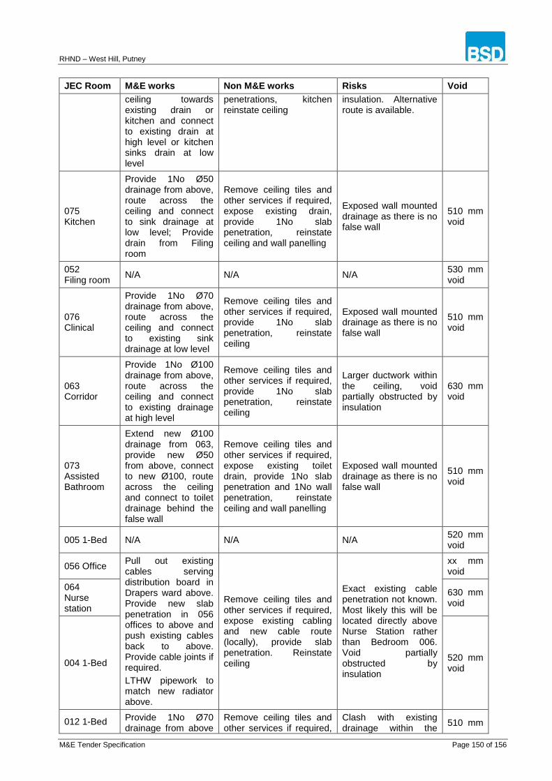
RHND – West Hill, Putney
M&E Tender Specification Page 150 of 156
JEC Room M&E works Non M&E works Risks Void
ceiling towards existing drain or kitchen and connect to existing drain at high level or kitchen sinks drain at low level
penetrations, kitchen reinstate ceiling
insulation. Alternative route is available.
075 Kitchen
Provide 1No Ø50 drainage from above, route across the ceiling and connect to sink drainage at low level; Provide drain from Filing room
Remove ceiling tiles and other services if required, expose existing drain, provide 1No slab penetration, reinstate ceiling and wall panelling
Exposed wall mounted drainage as there is no false wall
510 mm void
052 Filing room
N/A N/A N/A 530 mm void
076 Clinical
Provide 1No Ø70 drainage from above, route across the ceiling and connect to existing sink drainage at low level
Remove ceiling tiles and other services if required, provide 1No slab penetration, reinstate ceiling
Exposed wall mounted drainage as there is no false wall
510 mm void
063 Corridor
Provide 1No Ø100 drainage from above, route across the ceiling and connect to existing drainage at high level
Remove ceiling tiles and other services if required, provide 1No slab penetration, reinstate ceiling
Larger ductwork within the ceiling, void partially obstructed by insulation
630 mm void
073 Assisted Bathroom
Extend new Ø100 drainage from 063, provide new Ø50 from above, connect to new Ø100, route across the ceiling and connect to toilet drainage behind the false wall
Remove ceiling tiles and other services if required, expose existing toilet drain, provide 1No slab penetration and 1No wall penetration, reinstate ceiling and wall panelling
Exposed wall mounted drainage as there is no false wall
510 mm void
005 1-Bed N/A N/A N/A 520 mm void
056 Office Pull out existing cables serving distribution board in Drapers ward above. Provide new slab penetration in 056 offices to above and push existing cables back to above. Provide cable joints if required.
LTHW pipework to match new radiator above.
Remove ceiling tiles and other services if required, expose existing cabling and new cable route (locally), provide slab penetration. Reinstate ceiling
Exact existing cable penetration not known. Most likely this will be located directly above Nurse Station rather than Bedroom 006. Void partially obstructed by insulation
xx mm void
064 Nurse station
630 mm void
004 1-Bed 520 mm void
012 1-Bed Provide 1No Ø70 drainage from above
Remove ceiling tiles and other services if required,
Clash with existing drainage within the
510 mm

RHND – West Hill, Putney
M&E Tender Specification Page 151 of 156
JEC Room M&E works Non M&E works Risks Void
and connect to existing drainage at high level
Slightly re-route LTHW pipework to match new radiator above.
provide slab penetrations, reinstate ceiling
ceiling. void
007 Assisted Bathroom
Provide Ø70 drainage from 013 high level and connect to existing toilet drain at low level.
Slightly re-route LTHW pipework to match new radiator above.
Remove ceiling tiles and other services if required, provide 1No wall penetration and slab penetrations, reinstate ceiling
Clash with existing services within the ceiling.
510 mm void
013 1-Bed
Provide 1No Ø70 drainage from above, route across the ceiling and towards 007.
Slightly re-route LTHW pipework to match new radiator above.
Remove ceiling tiles and other services if required, provide slab penetrations and wall penetration, reinstate ceiling
Clash with existing services within the ceiling.
510 mm void
003 1-Bed N/A N/A N/A 520 mm void
002 1-Bed
Provide 1No Ø50 drainage from above, route across the ceiling and connect to existing drainage at high level
Remove ceiling tiles and other services if required, provide 1No slab penetration, reinstate ceiling and plastering
Clash with existing services within the ceiling.
510 mm void
001 1-Bed
Provide 1No Ø100, 2No Ø70 drainage from above, route across the ceiling and connect to existing drainage at high level
Remove ceiling tiles and other services if required, provide 3No slab penetration, reinstate ceiling
Existing drainage from above
550 mm void
057 Office
Provide 1No Ø50 drainage from above, route across the ceiling and connect to existing drainage at high level
Remove ceiling tiles and other services if required, provide 1No slab penetration, reinstate ceiling
Clash with existing wall.
550 mm void
059 Bin store
Provide 1No Ø50 drainage from above, route across the ceiling and connect to existing drainage at high level
Remove ceiling tiles and other services if required, provide 1No slab penetration, reinstate ceiling
Clash with existing wall or service within the ceiling.
xx mm void
062 Corridor
N/A N/A Larger ductwork within the ceiling
640 mm void

RHND – West Hill, Putney
M&E Tender Specification Page 152 of 156
JEC Room M&E works Non M&E works Risks Void
014 1-Bed N/A N/A N/A 510 mm
void
015 1-Bed N/A N/A N/A 510 mm
void
050 Store/Multipurpose
Re-connect re-routed AC refrigerant pipework
N/A N/A
510 mm void
Hall Entrance
N/A N/A N/A 640 mm
void
Note:
1. The following bedrooms will not be directly affected by above works: 003, 004, 005, 007, 009, 010,
014 and 015.
2. The above works will have minor impact on the following bedrooms: 012 and 013.
3. The highest impact will be on south side Bedrooms: 001, 002 and 006.
4. Other rooms affected by works include: Assisted showers and bathrooms, Staff WC, Sluice, Kitchen,
Day room, Offices, Bin Store, Corridors, Clinical and Nurse Station.
5. Where pipework is horizontally crossing more than one room, both rooms will need to be done at the
same time. This applies to the following room pairs: 063&073, 065&072, 064&056(&004), 007&013,
057&001.
JEC ceiling Void survey drawing Note: Access and close co-operation with the Hospital will be also required when installing high level drainage within Alexandra’s Wing Ground Floor areas.
RHND – West Hill, Putney
M&E Tender Specification Page 153 of 156
APPENDIX C – MECHANICAL EQUIPMENT DATA SHEETS
(Refer to a separate pdf file)
RHND – West Hill, Putney
M&E Tender Specification Page 154 of 156
APPENDIX D – ELECTRICAL DISTRIBUTION BOARD SCHEDULES
(Refer to a separate pdf file)
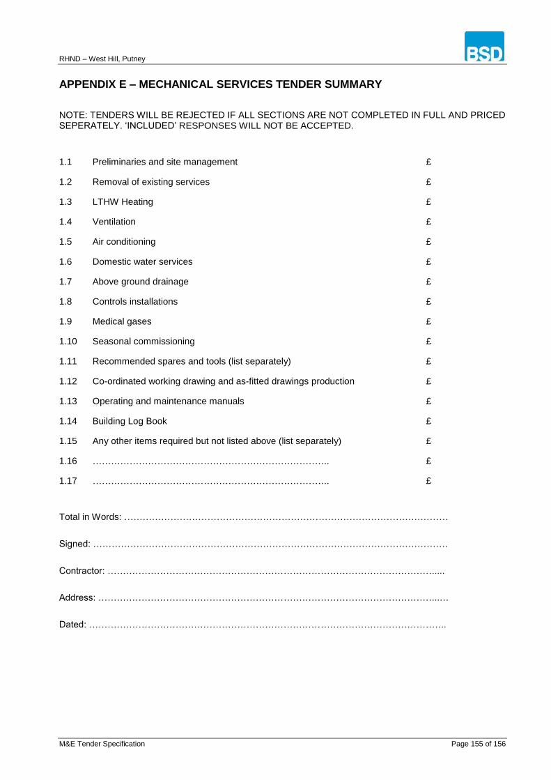
RHND – West Hill, Putney
M&E Tender Specification Page 155 of 156
APPENDIX E – MECHANICAL SERVICES TENDER SUMMARY
NOTE: TENDERS WILL BE REJECTED IF ALL SECTIONS ARE NOT COMPLETED IN FULL AND PRICED SEPERATELY. ‘INCLUDED’ RESPONSES WILL NOT BE ACCEPTED.
1.1 Preliminaries and site management £
1.2 Removal of existing services £
1.3 LTHW Heating £
1.4 Ventilation £
1.5 Air conditioning £
1.6 Domestic water services £
1.7 Above ground drainage £
1.8 Controls installations £
1.9 Medical gases £
1.10 Seasonal commissioning £
1.11 Recommended spares and tools (list separately) £
1.12 Co-ordinated working drawing and as-fitted drawings production £
1.13 Operating and maintenance manuals £
1.14 Building Log Book £
1.15 Any other items required but not listed above (list separately) £
1.16 ………………………………………………………………….. £
1.17 ………………………………………………………………….. £
Total in Words: ……………………………………………………………………………………………
Signed: …………………………………………………………………………………………………….
Contractor: …………………………………………………………………………………………….....
Address: ………………………………………………………………………………………………...…
Dated: ……………………………………………………………………………………………………..

RHND – West Hill, Putney
M&E Tender Specification Page 156 of 156
APPENDIX F – ELECTRICAL SERVICES TENDER SUMMARY
NOTE: TENDERS WILL BE REJECTED IF ALL SECTIONS ARE NOT COMPLETED IN FULL AND PRICED SEPERATELY. ‘INCLUDED’ RESPONSES WILL NOT BE ACCEPTED.
2.1 Preliminaries and site management £
2.2 Removal of existing services £
2.3 Coordinated working drawing production £
2.4 LV distribution £
2.5 Small power £
2.6 Lighting, Emergency lighting and lighting controls £
2.8 Cable containment £
2.10 Fire alarm £
2.11 Nurse Call, WC & Panic alarm and Wander Guard Systems £
2.12 Intercom & Access Control System £
2.13 Data cabling/outlets £
2.14 Electrical testing and commissioning £
2.15 As-fitted drawings £
2.16 Operating and maintenance manuals £
2.17 Any other items not listed above (list separately) £
2.18 …………………………………………………........ £
2.19 …………………………………………………........ £
2.20 …………………………………………………........ £
Total in Words: ……………………………………………………………………………………………
Signed: …………………………………………………………………………………………………….
Contractor: …………………………………………………………………………………………….....
Address: ………………………………………………………………………………………………...…
Dated: ……………………………………………………………………………………………………..