National Crane 1300H Seriesdchcrane.com/wp-content/uploads/2016/05/National_Crane_1300H... ·...
16
National Crane 1300H Series Product Guide Features • All new design • 33,52 m (110 ft) four-section boom • 27,2 t (30 USt) rating • Multi-position Easy Reach control panel
Transcript of National Crane 1300H Seriesdchcrane.com/wp-content/uploads/2016/05/National_Crane_1300H... ·...

National Crane 1300H SeriesProduct Guide
Features
• All new design
• 33,52 m (110 ft) four-section boom
• 27,2 t (30 USt) rating
• Multi-position Easy Reach control panel

Features
Boom The 110 ft four-section boom is the lon-gest in its size range. The longer boom allows the operator to perform more lifts without the use of a jib, reducing setup time and improving efficiency. A 69 ft four-section boom or a 100 ft four-section boom are also available.
Easy Reach control stationThe Easy Reach control station can be tilted to the right or left side of the crane as needed and can be stowed in the center position for transport. The single axis pilot operated crane controls allow smooth operation for each crane function.
Overload protection All National Crane boom trucks are equipped with overload protection. A Load Moment Indicator (LMI) is standard on all Series 1300H machines with Work Area Definition System (WADS). The LMI display console is weatherproof and the LCD display is visible in full or low light. All crane load lifting values are displayed simultaneously.
Outriggers Two sets of “HO”-style outriggers with 6 m (20 ft) full span, a 4,2 m (14 ft) mid span setting with manual locks and reduced capacity chart and fully retracted outrigger spread with reduced capacity chart. Main outriggers are equipped with removable ball and socket aluminum foot pads. Independent outrigger controls (umbilical design) are located at the easy reach control console and includes level indicator (sight bubble).
Torsion box The stronger standard torsion box improves
rigidity, reduces truck frame flex and reduces the need for counterweight.
Features
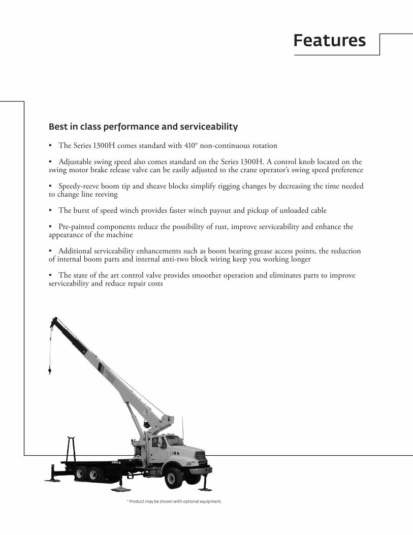
Best in class performance and serviceability
The Series 1300H comes standard with 410° non-continuous rotation•
Adjustable swing speed also comes standard on the Series 1300H. A control knob located on the • swing motor brake release valve can be easily adjusted to the crane operator’s swing speed preference
Speedy-reeve boom tip and sheave blocks simplify rigging changes by decreasing the time needed • to change line reeving
The burst of speed winch provides faster winch payout and pickup of unloaded cable•
Pre-painted components reduce the possibility of rust, improve serviceability and enhance the • appearance of the machine
Additional serviceability enhancements such as boom bearing grease access points, the reduction • of internal boom parts and internal anti-two block wiring keep you working longer
The state of the art control valve provides smoother operation and eliminates parts to improve • serviceability and reduce repair costs
* Product may be shown with optional equipment.

4
Contents
Features 2
Mounting configuration 5
Specifications 6
Capacities 8
Dimensions 11
Accessories 12
Notes 13

5Series 1300H
Mounting configuration
The mounting configuration is based on an 85% stability factor. If the bare truck weight requirements are not met, counterweight will be required. The complete unit must be installed on the truck in accordance with factory requirements. Since individual truck chassis vary, a test must be performed on the unit to verify actual stability after mounting and installing counterweight (if required). A summary of mounting and truck requirements are:
For 180° working area – Gross Axle Weight Rating Front (GAWR) – 8165 kg (18,000 lb)Gross Axle Weight Rating Rear (GAWR) – 15 455 kg (34,000 lb)Gross Vehicle Weight Rating (GVW) – 23 587 kg (52,000 lb)Wheelbase (WB) – 6,65 m (262 in)Cab to Axle Trunnion (CT) – 4,88 m (192 in)After Frame (AF) – 2,67 m (105 in)Frame Section Modulus (SM) from outrigger to RSOD – 327 cm3 (20 in3) and 759 MPa (110,000 psi) materialBare Chassis Weight required for stability prior to installationFront – 3692 kg (8140 lb)Rear – 4028 kg (8880 lb)
For 360° working area – Optional Single Front Stabilizer (SFO)Gross Axle Weight Rating Front (GAWR) – 8165 kg (18,000 lb)Gross Axle Weight Rating Rear (GAWR) – 15 455 kg (34,000 lb)Gross Vehicle Weight Rating (GVW) – 23 587 kg (52,000 lb )Wheelbase (WB) – 6,65 m (262 in)Cab to Axle Trunnion (CT) – 4,88 m (192 in)After Frame (AF) – 2,67 m (105 in)Frame Section Modulus (SM) from front spring hanger to end of after frame – 327 cm3 (30 in3) and 759 MPa (110,000 psi) materialBare Chassis Weight required for stability prior to installationFront – 3720 kg (8200 lb)Rear – 4037 kg (8900 lb)
For 360° stability the truck frame must have a 492 cm3 (30 in3) section modulus [372 850 Nm (3,300,000 in-lb) RBM] minimum under the crane frame, 295 cm3 (18 in3) section modulus [223 710 Nm (1,980,000 in-lb) RBM] at the front spring rear hanger, 197 cm3 (12 in3) section modulus [149 140 Nm (1,320,000 in-lb) RBM] through the front spring and 49 cm3 (3 in3) section modulus [37 284 Nm (330,000 in-lb) RBM] at the stabilizer attachment point on each truck frame rail.
Notes:Gross Vehicle Weight Rating (GVWR) is dependent on •
all components of the vehicle (axles, tires, springs, fame, etc.) meeting manufacturers’ recommendations; always specify GVWR when purchasing trucks
Diesel engines require a variable speed governor and • energize-to-run fuel solenoid for smooth crane operation; electronic fuel injection is required
All mounting data is based on a National Series 1300H • with subbase and an 85% stability factor
The complete unit must be installed in accordance with • factory requirements, and a test performed to determine actual stability and counterweight requirements; contact the factory for details
Transmission neutral safety interlock switch is required• 13100H with front center stabilizer will be approximate •
40 ft overall length. 13110H will exceed 40 ft overall length
FRONT JACKREQUIRED FOR ���o
WORK AREA
���.� MIN.
���.� MIN.���.� MIN.
���� BARE MIN.����� GARW MIN.*ALL DIMENSIONS INCHES AND POUNDS.
���� BARE MIN.����� GARW MIN.
�.� MIN.
���o
FULL CAPACITYWORK AREA
Note: Chassis will require extended front frame rails for SFO addition.
THIS CHART IS ONLY A GUIDE AND SHOULD NOT BE USED TO OPERATE THE CRANE. The individual crane’s load chart, operating instructions and other instructional plates must be read and understood prior to operating the crane.

6
Specifications
Available in three basic models:
Boom and jib combinations data
Model 13100H – Equipped with a 8,83 m - 30,48 m (29 ft - 100 ft) four-section boom. This model can be equipped with a 7,62 m - 13,41 m (25 ft - 44 ft) two section jib. Max i mum tip height with 13,41 m (44 ft) jib is 44,63 m (153 ft).
Model 1369H – Equipped with a 6,7 m - 21,03 m (22 ft - 69 ft) four-section boom. Max i mum tip height is 23,77 m (78 ft).
8,83 m - 30,48 m (29 ft -100 ft) four-section boom. 13FJ44M 7,62 m - 13,41 m (25 ft - 44 ft) two-section jib
6,7 m - 21,03 m (22 ft - 69 ft) four-section boom.
Model 13110H – Equipped with a 10,05 m - 33,52 m (33 ft - 110 ft) four-section boom. This model can be equipped with a 7,62 m - 13,41 m (25 ft - 44 ft) two-section jib. Max i mum tip height with 13,41 m (44 ft) jib is 49,68 m (163 ft).
10,05 m - 33,52 m (33 ft - 110 ft) four-section boom. 13FJ44M 7,62 m - 13,41 m (25 ft - 44 ft) two-section jib
Note: Maximum tip height is measured with outriggers/stabilizers fully extended.
THIS CHART IS ONLY A GUIDE AND SHOULD NOT BE USED TO OPERATE THE CRANE. The individual crane’s load chart, operating instructions and other instructional plates must be read and understood prior to operating the crane.

7Series 1300H
Specifications
1300H winch data
Do not deadhead line block • against boom tip when extending boom
Keep at least three wraps of • loadline on drum at all times
Use only 9/16 in diameter • rotation-resistant cable with 38,500 lb breaking strength on this machine
1 part line 2 part line 3 part line 4 part line 5 part line 6 part line 7 part line
69 ft boom 69 ft 69 ft 61 ft 51 ft 31 ft 21 ft
144 ft boom jib 100 ft 86 ft 58 ft 44 ft 44 ft 29 ft
154 ft boom jib 110 ft 78 ft 62 ft 46 ft 46 ft 32 ft
MAXIMUM BOOM LENGTH AT MAXIMUM ELEVATION WITH RIG-
GING SHOWN WITH LOAD BLOCK AT GROUND LEVEL
WinchAverage
cable supplied
Breaking strength
Lift and speed
Lift and speed
Lift and speed
Lift and speed
Lift and speed
Lift and speed
Lift and speed
Standard planetary
winch
9/16 in Diameter rotation resistant
17 464 kg (38,500 lb)
3493 kg (7700 lb)
50 m/min (164 fpm)
6986 kg (15,400 lb)
25 m/min (82 fpm)
10 478 kg (23,100 lb)
16 m/min (55 fpm)
13 971 kg (30,800 lb)
12 m/min (41 fpm)
17 464 kg (38,500 lb)
10 m/min (33 fpm)
20 956 kg (46,200 lb)
8 m/min (27 fpm)
24 449 kg (53,900 lb)
7 m/min (23 fpm)
“Burst of speed”
9/16 in Diameter rotation resistant
17 464 kg (38,500 lb)
1361 kg (3000 lb)
111 m/min (265 fpm)
2722 kg (6000 lb)
40 m/min (132 fpm)
4083 kg (9000 lb)
27 m/min (88 fpm)
5443 kg (12,000 lb)
20 m/min (66 fpm)
6804 kg (15,000 lb)
16 m/min (53 fpm)
8165 kg (18,000 lb)
13 m/min (44 fpm)
9526 kg (21,000 lb)
11 m/min (38 fpm)
All winch pulls and speeds in this chart are shown on the fourth layer. Winch line pulls would increase on the first, second and third layers. Winch line speed would decrease on the first, second and third layers. Winch line pulls may be limited by the winch capacity or the ANSI 5 to 1 cable safety factor. These are shown below:
Winch 4th layer drum pull Allowable cable pull
Standard planetary 3493 kg (7700 lb) (low speed) 3492 kg (7700 lb)
1361 kg (3000 lb) (“burst of speed”)
Block type Rating Weight
Downhaul weight 4,53 t (5 USt) 68 kg (150 lb)
1 Sheave Block 10,89 t (12 USt) 139 kg (305 lb)
2 Sheave Block 17,24 t (19 Ust) 159 kg (350 lb)
3 Sheave Block 27,22 t (30 Ust) 261 kg (575 lb)
THIS CHART IS ONLY A GUIDE AND SHOULD NOT BE USED TO OPERATE THE CRANE. The individual crane’s load chart, operating instructions and other instructional plates must be read and understood prior to operating the crane.

8
Capacities
Series 1369H: 21,03 m (69 ft) boom/full span outrigger and stabilizer
Load chart
Other Series 1300H Load Rating Charts are available. National Crane will send you a chart on request – or you may secure needed load rating information through your nearest National Crane dealer.
Notes:1. Operate with jib by radius when main boom is fully extended. If necessary increase boom angle to maintain loaded radius2. Operate with jib by boom angle when main boom is not fully extended. Do not exceed rated jib capacities at any reduced boom lengths
CAUTION:
Do not operate crane• booms, jib extensions, any accessories or loads within 3 m (10 ft) of live power lines or other conductors of electricity
Jib and boom capacities shown are maximum for each section• Do not exceed capacities at reduced radii• Load ratings shown on the appropriate charts are maximum •
allowable loads with the crane mounted on a factory-approved truck and all outriggers at either full span or at mid span range and set on a firm level surface so that the crane is level and all tires are suspended
Always level the crane with the level indicator located on the crane• The operator must reduce load to allow for factors such as wind, •
ground conditions, operating speeds and their effects on freely suspended loads
Overloading this crane may cause structural collapse or instability• Weights on any accessories attached to the boom or loadline must •
be deducted from the load chart capacitiesDo not deadhead lineblock against boom tip when extending •
boom or winching upKeep at least three wraps of loadline on drum at all times•
Use only specifie• d cable with this machine
THIS CHART IS ONLY A GUIDE AND SHOULD NOT BE USED TO OPERATE THE CRANE. The individual crane’s load chart, operating instructions and other instructional plates must be read and understood prior to operating the crane.
Operating radiusfrom C/L rotation
with unloaded boom
0 20 40 60 80
RADIUS IN FEET
0
20
40
60
80
100
HEI
GH
T IN
FEE
T
BO
OM
LEN
GTH
IN F
EET
��°��°
��°
��°
��°
��°
��°
��°
�°
���°
A
B
C
D
21
31
41
51
61
69
�� ftBOOM
�lb�
LOADEDBOOMANGLE�deg�
A�� ft
BOOM�lb�
LOADEDBOOMANGLE�deg�
B�� ft
BOOM�lb�
LOADEDBOOMANGLE�deg�
C�� ft
BOOM�lb�
LOADEDBOOMANGLE�deg�
D�� ft
BOOM�lb�
LOADEDBOOMANGLE�deg�
�� ft BOOM�lb�
LOADEDBOOMANGLE�deg�
LOADEDRADIUS
�ft�
����������������������������
��.���.�����
��.�
�
��.���.���.���.���.���.�
�
��.���
��.���.���.���.���.�
��
�
��.���.���
��.���.���.���.���.�
��
�
��.���.���.���.�����
��.���
��.���.�
�
��.���.���
��.���.���.���.�
����
��.���.�
�
* ��,�����,�����,�����,�����,���
��,���
��,�����,�����,�����,�����,�����,���
��,���
��,�����,�����,���
��,�����,�����,�����,�����,���
����
��,�����,�����,�����,�����,�����,�����,�����������
����
��,�����,�����,�����,�����,�����,�������������������
����
��,�����,�����,�����,�����,�������������������������������
Notes:
1. All capacities are in pounds, angles in degrees, and radii in feet2. Loaded boom angles are given as reference only3. Shaded areas are structurally limited capacities4. Handling of personnel is only permitted with full span extension of all outrigger and stabilizer beams.*5. See owners manuals. The 60,000 lb load requires optional 9/15 in diameter 6x25 IWRC cable

9Series 1300H
Capacities
Load chart
Series 13100H: 8,99 m - 30,48 m (25 ft - 44 ft) jib/full span outrigger and stabilizer
THIS CHART IS ONLY A GUIDE AND SHOULD NOT BE USED TO OPERATE THE CRANE. The individual crane’s load chart, operating instructions and other instructional plates must be read and understood prior to operating the crane.
Other Series 1300H Load Rating Charts are available. National Crane will send you a chart on request – or you may secure needed load rating information through your nearest National Crane dealer.
CAUTION:Do not operate crane booms, jib extensions, any accessories or •
loads within 3 m (10 ft) of live power lines or other conductors of electricity
Jib and boom capacities shown are maximum for each section• Do not exceed capacities at reduced radii• Load ratings shown on the load rating charts are maximum •
allowable loads with the outriggers properly extended and the outrigger lock pins engaged on a firm, level surface and the crane leveled and mounted on a factory recommended truck
Always level the crane with the level indicator located on the crane• The operator must reduce load to allow for factors such as wind, •
ground conditions, operating speeds and their effects on freely suspended loads
Overloading this crane may cause structural collapse or instability• Weights on any accessories attached to the boom or loadline must •
be deducted from the load chart capacitiesDo not deadhead lineblock against boom tip when extending boom •
or winching upKeep at least three wraps of loadline on drum at all times• Use only specified cable with this machine•
Notes:1. Operate with jib by radius when main boom is fully extended. If necessary increase boom angle to maintain loaded radius2. Operate with jib by boom angle when main boom is not fully extended. Do not exceed rated jib capacities at any reduced boom lengths
� �� �� �� �� ���
RADIUS IN FEET
�
��
��
��
��
���
���
���
���
HEI
GH
T IN
FEE
T
�st Jib��'
�nd Jib��'
BO
OM
LEN
GTH
IN F
EET
��
��
���
��
��
��
CBA D
80°
70°
60°
50°
40°
42.4°
42.8°
30°
20°
10°
0°-10°
Structural LimitLine with 150 lb Block
Structural LimitLine with 44' JibErected
Structural Limit Linewith 25' Jib Erected
Stability LimitLine with 150 lb Block
Stability LimitLine with 150 lb Block
Do not move unloaded boom
beyond limit line.
Operating radiusfrom C/L rotation
with unloaded boom
�� ft � ��� ft BOOM RATED LOADS WITHOUT JIB
�� ftBOOM
�lb�
LOADEDBOOMANGLE�deg�
A�� ft
BOOM�lb�
LOADEDBOOMANGLE�deg�
B�� ft
BOOM�lb�
LOADEDBOOMANGLE�deg�
C�� ft
BOOM�lb�
LOADEDBOOMANGLE�deg�
D�� ft
BOOM�lb�
LOADEDBOOMANGLE�deg�
��� ftBOOM
�lb�
LOADEDBOOMANGLE�deg�
LOADEDRADIUS
�ft�
����������������������������������������
��.���.���.���.���.���.���.�
�
��.���.���.���.���.���.���.���.���.�
�
����.���.���.���.���.�����
��.�
�
����.���.���.���.���.���.���.���.���.���.�
�
��.���.���
��.���.���.���.���.���.���.���.���.���.�
�
��.���.���.���.���.���.���
��.���.���.���.���.���.���.���.���.�
�
* ��,�����,�����,�����,�����,�����,�����,���
��,���
��,�����,�����,�����,�����,�����,�����,�����,�������
����
��,�����,�����,�����,�����,�����,���������������
����
��,�����,�����,�����,�����,���������������������������
����
��,�����,�����,���
��,���������������������������������������
����
��,�����,�����,���������������������������������������������������������
RATED LOAD REDUCTIONS WITH STOWED JIB
�� ft � �� ft JIB STOWED
BOOMLENGTH
�ft�
��
��
��
��
��
���
Reduce load ��� lb
Reduce load ��� lb
Reduce load ��� lb
Reduce load ��� lb
Reduce load ��� lb
Reduce load ��� lb
�� ft � �� ft JIB RATED LOADS
�� ftJIB�lb�
LOADEDBOOMANGLE
�deg�
�� ftJIB�lb�
LOADEDBOOMANGLE
�deg�
LOADEDRADIUS
�ft�
��������������������������
���������
��.���.���.���.���.���.���.���.���.���.���.���.���.�
��.���.���.���.���.�
����.���.�
����
��.���.�
����.�
���������������������������������������������������
�����������������������������������������������������
Notes:1. All capacities are in pounds, angles in degrees, and radii in feet2. Loaded boom angles are given as reference only3. Shaded areas are structurally limited capacities4. Handling of personnel is only permitted with full span extension of all outrigger and stabilizer beams.*5. See owners manuals. The 60,000 lb load requires optional 9/15 in diameter 6x25 IWRC cable

10
Capacities
Series 13110H: 9,75 m - 33,53m (25 ft - 44 ft) jib/full span outrigger and stabilizer
Load chart
Other Series 1300H Load Rating Charts are available. National Crane will send you a chart on request - or you may secure needed load rating information through your nearest National Crane dealer.
Notes:1. Operate with jib by radius when main boom is fully extended. If necessary increase boom angle to maintain loaded radius2. Operate with jib by boom angle when main boom is not fully extended. Do not exceed rated jib capacities at any reduced boom lengths
CAUTION:
Do not operate crane booms, jib extensions, any accessories or • loads within 3 m (10 ft) of live power lines or other conductors of electricity
Jib and boom capacities shown are maximum for each section• Do not exceed capacities at reduced radii• Load ratings shown on the appropriate charts are maximum •
allowable loads with the crane mounted on a factory-approved truck and all outriggers at either full span or at mid span range and set on a firm level surface so that the crane is level and all tires are suspended
Always level the crane with the level indicator located on the crane• The operator must reduce load to allow for factors such as •
wind, ground conditions, operating speeds and their effects on freely suspended loads
Overloading this crane may cause structural collapse or instability• Weights on any accessories attached to the boom or loadline must •
be deducted from the load chart capacitiesDo not deadhead lineblock against boom tip when extending •
boom or winching upKeep at least three wraps of loadline on drum at all times• Use only specified cable with this machine•
THIS CHART IS ONLY A GUIDE AND SHOULD NOT BE USED TO OPERATE THE CRANE. The individual crane’s load chart, operating instructions and other instructional plates must be read and understood prior to operating the crane.
Do not move unloaded boom
beyond limit line.
Operating radiusfrom C/L rotation
with unloaded boom
0 20 40 60 80 100 120
RADIUS IN FEET
0
20
40
60
80
100
120
140
160
HEI
GH
T IN
FEE
T
1st Jib25'
2nd Jib44'
BO
OM
LEN
GTH
IN F
EET
62
94
110
78
32
46
CBA D
80°
70°
60°
40°
30°
20°
10°
0°-10°
50°
48°
Structural LimitLine with 44' JibErected
Structural Limit Linewith 25' Jib Erected
Stability Limit Line with 150 lbBlock
50.8°
�� ft � ��� ft BOOM RATED LOADS WITHOUT JIB
�� ftBOOM
�lb�
LOADEDBOOMANGLE�deg�
A�� ft
BOOM�lb�
LOADEDBOOMANGLE�deg�
B�� ft
BOOM�lb�
LOADEDBOOMANGLE�deg�
C�� ft
BOOM�lb�
LOADEDBOOMANGLE�deg�
D�� ft
BOOM�lb�
LOADEDBOOMANGLE�deg�
��� ftBOOM
�lb�
LOADEDBOOMANGLE�deg�
LOADEDRADIUS
�ft�
�������������������������������������������
��.���.���.���.���.���.���.�
�
��.���.���.���.���.�����.���.���.�
�
����.���.���.���.���.���.�������.�
�
����.���.���.�����.���.���.�������.���.�
�
����.���.���.���.���.���.���.���.���.���.���.���.���.���.�
�
��.�
��.�
��.�
��.�
��.�
��.�
��.�
��.�
��.�
��.�
��.�
��.�
��.�
��.�
��.�
��.�
* ��,�����,�����,�����,�����,�����,�����,���
����
��,�����,�����,�����,�����,�����,�����,�����������
����
��,�����,�����,�����,�����,�����������������������
����
��,�����,�����,�����,�����������������������������������
����
��,�����,�����,���
��,����������������������������������������������
���
��,�������������������������������������������������������������
RATED LOAD REDUCTIONS WITH STOWED JIB
�� ft � �� ft JIB STOWED
BOOMLENGTH
�ft�
��
��
��
��
��
���
Reduce load ��� lb
Reduce load ��� lb
Reduce load ��� lb
Reduce load ��� lb
Reduce load ��� lb
Reduce load ��� lb
�� ft � �� ft JIB RATED LOADS
�� ftJIB�lb�
LOADEDBOOMANGLE�deg�
�� ftJIB�lb�
LOADEDBOOMANGLE�deg�
LOADEDRADIUS
�ft�
��
��
��
��
��
��
��
��
��
��.�
��.�
��.�
��.�
��.�
��.�
��.�
��.�
��.�
��.�
��.�
��.�
��.�
��.�
����
����
����
����
����
����
���
����
����
����
����
����
���
���
Notes:1. All capacities are in pounds, angles in degrees, and radii in feet2. Loaded boom angles are given as reference only3. Shaded areas are structurally limited capacities4. Handling of personnel is only permitted with full span extension of all outrigger and stabilizer beams.*5. See owners manuals. The 60,000 lb load requires optional 9/15 in diameter 6x25 IWRC cable
11Series 1300H
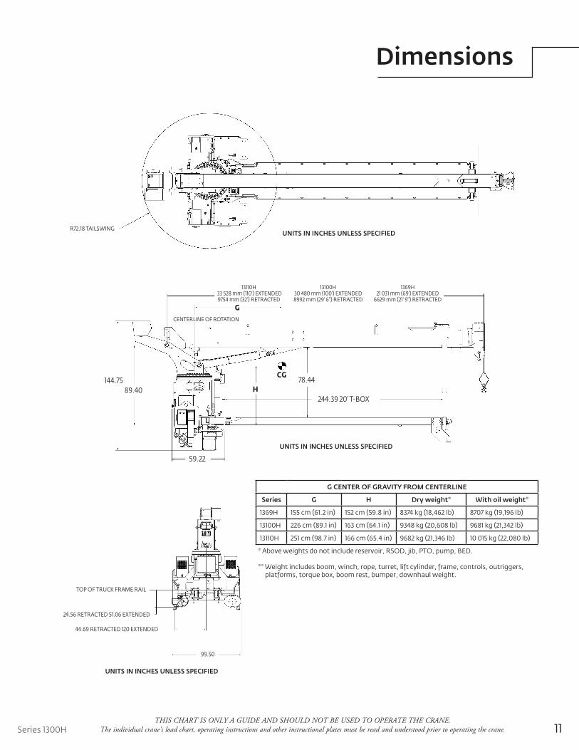
CENTERLINE OF ROTATION
CG78.44144.75
89.40
59.22
H
G
244.39 20' T-BOX
13110H 33 528 mm (110') EXTENDED9754 mm (32') RETRACTED
13100H30 480 mm (100') EXTENDED8992 mm (29' 6") RETRACTED
1369H21 031 mm (69') EXTENDED
6629 mm (21' 9") RETRACTED
Dimensions
R��.�� TAILSWINGUNITS IN INCHES UNLESS SPECIFIED
TOP OF TRUCK FRAME RAIL
��.�� RETRACTED ��.�� EXTENDED
��.�� RETRACTED ��� EXTENDED
��.��
* Above weights do not include reservoir, RSOD, jib, PTO, pump, BED.
** Weight includes boom, winch, rope, turret, lift cylinder, frame, controls, outriggers, platforms, torque box, boom rest, bumper, downhaul weight.
G CENTER OF GRAVITY FROM CENTERLINE
Series G H Dry weight* With oil weight*
1369H 155 cm (61.2 in) 152 cm (59.8 in) 8374 kg (18,462 lb) 8707 kg (19,196 lb)
13100H 226 cm (89.1 in) 163 cm (64.1 in) 9348 kg (20,608 lb) 9681 kg (21,342 lb)
13110H 251 cm (98.7 in) 166 cm (65.4 in) 9682 kg (21,346 lb) 10 015 kg (22,080 lb)
THIS CHART IS ONLY A GUIDE AND SHOULD NOT BE USED TO OPERATE THE CRANE. The individual crane’s load chart, operating instructions and other instructional plates must be read and understood prior to operating the crane.
UNITS IN INCHES UNLESS SPECIFIED
UNITS IN INCHES UNLESS SPECIFIED

12
Accessories
Radio Remote Controls – Eliminate the handling and maintenance concerns that accompany cabled remotes. Operate to a range of about 76 m (250 ft), varying with conditions. • NB4R
One-Person Basket – Strong but lightweight steel basket with 139 kg (300 lb) capacity, gravity hung • B1-Swith swing lock and full body harness. • 2B1-S (for dual locking baskets)
Heavy-duty Personnel Basket – 544 kg (1200 lb) capacity steel basket with safety loops for two passengers. Gravity leveling 183 cm x 107 cm (72 in x 42 in) platform. Fast attachment and secure locking • BSA-1systems. Load chart must show 1043 kg (2300 lb) minimum to operate this accessory. • BSA-R1 (provides rotation)
Winch Drum Rotation Indicator • WDRI
Last Wrap Indicator Option on winch with indicator on Easy Reach console. • LLI
Single Front Outrigger Center front stabilizer with a 25 in vertical stroke • SFO
Steel Tool Box Options
Bulkhead-steel for super-duty beds • BHSD

13Series 1300H
Notes

14
Notes

15Series 1300H
Notes

www.manitowoc.com
©2009 ManitowocPrinted in USAForm No. Series 1300H PGPart No. 1300H / 0809 / 2.5M
Regional headquarters
Manitowoc - AmericasManitowoc, Wisconsin, USA Tel: +1 920 684 6621 Fax: +1 920 683 6277 Shady Grove, Pennsylvania, USA Tel: +1 717 597 8121 Fax: +1 717 597 4062
Manitowoc - Europe, Middle East & AfricaEcully, France Tel: +33 (0)4 72 18 20 20 Fax: +33 (0)4 72 18 20 00
Manitowoc - Asia PacificShanghai, China Tel: +86 21 6457 0066Fax: +86 21 6457 4955
Regional officesThis document is non-contractual. Constant improvement and engineering progress make it necessary that we reserve the right to make specification, equipment, and price changes without notice. Illustrations shown may include optional equipment and accessories and may not include all standard equipment.
AmericasBrazilAlphavilleMexicoMonterreyChileSantiago
Europe, Middle East & AfricaAlgeriaHydraCzech RepublicNetvoriceFranceBaudemontCergyDecinesGermanyLangenfeldHungaryBudapestItalyParabiagoNetherlandsBredaPolandWarsaw
PortugalBaltarLisbonRussiaMoscowU.A.E.DubaiU.K.Gawcott
Asia - PacificAustraliaBrisbaneMelbourneSydneyChinaBeijingXi’anIndiaHyderabadPuneKoreaSeoulPhilippinesMakati CitySingapore
FactoriesBrazilAlphavilleChinaTaiAnZhangjiagangFranceCharlieuLa ClayetteMoulinsGermanyWilhelmshavenIndiaPuneItalyNiella TanaroPortugalBaltarFânzeresSlovakiaSarisUSAManitowoc Port WashingtonShady Grove