
NATIONAL ANNEX TO STANDARD SFS-EN 1993-1-3 EUROCODE 3 ... NA-FIN SET II Ministery of... · SFS-EN...
34
ANNEX 19 NATIONAL ANNEX TO STANDARD SFS-EN 1993-1-3 EUROCODE 3: DESIGN OF STEEL STRUCTURES. Part 1-3: General Rules. Supplementary rules for cold-formed members and sheeting Preface This national annex is used together with Standard SFS - EN 1993-1-3:2006. This national annex sets out: a) The national parameters for the following clauses in Standard SFS-EN 1993-1-3 where national selection is permitted: - 2(3)P - 2(5) - 3.1(3) Note 1 and Note 2 - 3.2.4(1) - 5.3(4) - 8.3(5) - 8.3.13, Table 8.1 - 8.3(13) Table 8.2 - 8.3(13) Table 8.3 - 8.3(13) Table 8.4 - 8.4(5) - 8.5.1(4) - 9(2) - 10.1.1(1) - 10.1.4.2(1) - A.1(1), Note 2 - A.1(1), Note 3 - A.6.4(4) - E(1). b) Guidance for the use of Annexes A, B, C, D and E.
-
Upload
truongnguyet -
Category
Documents
-
view
233 -
download
3
Transcript of NATIONAL ANNEX TO STANDARD SFS-EN 1993-1-3 EUROCODE 3 ... NA-FIN SET II Ministery of... · SFS-EN...
ANNEX 19
NATIONAL ANNEX
TO STANDARD
SFS-EN 1993-1-3 EUROCODE 3: DESIGN OF STEEL STRUCTURES. Part 1-3: General Rules. Supplementary rules for cold-formed members and sheeting
Preface This national annex is used together with Standard SFS - EN 1993-1-3:2006. This national annex sets out: a) The national parameters for the following clauses in Standard SFS-EN 1993-1-3 where national
selection is permitted:
- 2(3)P - 2(5) - 3.1(3) Note 1 and Note 2 - 3.2.4(1) - 5.3(4) - 8.3(5) - 8.3.13, Table 8.1 - 8.3(13) Table 8.2 - 8.3(13) Table 8.3 - 8.3(13) Table 8.4 - 8.4(5) - 8.5.1(4) - 9(2) - 10.1.1(1) - 10.1.4.2(1) - A.1(1), Note 2 - A.1(1), Note 3 - A.6.4(4) - E(1).
b) Guidance for the use of Annexes A, B, C, D and E.

2
2 Basis of Design 2(3)P The recommended values should be used. The rules for sheeting given in the National Annex for standard SFS-EN 1990 may be used only in the cases, where the production of the sheeting is under the control of third party. 2(5) The recommended value should be used. 3.1 General 3.1 (3), Note 1 Recommended value should be used if it can not be shown, that the values given in the table 3.1a are reached in the rolling direction and perpendicular to the rolling direction. 3.1(3), Note 2 Steels according to table 3.1b may be used. If higher values than given in the table 3.1b are used for steels according to standard SFS-EN 10327, fulfilment of the strength values should be verfied by material sertificates, which are valid for the material used. The rules according to standard SFS-EN 1993-1-3 may be applied for steels according to standard SFS-EN 10025-5. The rules according to standard SFS-EN 1993-1-3 may be applied to steel according to standard SFS-EN 10025-6, if the limitations given in standards SFS-EN 1993-1-3 and SFS-EN 1993-1-12 are taken into account. Other steel grades may be used according to valid product approval. 3.2.4 Thickness and thickness tolerances 3.2.4(1) The recommended values should be used. 5.3 Structural modeling for analysis 5.3(4) The recommended values should be used. 7.1 General 7.1(1) Explanation: Guidance given in the National Annex of standard SFS-EN 1993-1-1 should be applied. For crane supporting structures, see National Annex of standard SFS-EN 1993-6.

3
8.3 Connections made with mechanical fasteners 8.3(5), Table 8.1 The recommended value should be used. The values given in the table 8.1a may be used provided, that valid product approval is available for the product. In this case the design tensile resistance for the rivet should be calculated as follows:
RdvRdt FF ,, = = Fv,Rk /γM2 (8.1 FI)
Table 8.1a (FI) Charcteristic shear strengths for blind rivet Fv,Rk (N/rivet)
Material of the rivet 1) Diameter of the shank
(mm) Steel Stainless steel Monel-metal 2) Alumium
4,0 1600 2800 2400 800
4,8 2400 4200 3500 1100
5,0 2600 4600 - -
6,4 4400 - 6200 2000
1) According to the applied standard or according to certified product declaration.
2) Nickel-copper alloy containing two parts nickel and one part copper.
Greater values than given in the table 8.1a may be given in the valid product approval, if they are based on testing and the tests results are analysed according to Annex D of SFS-EN 1990 taking National Annex for SFS-EN 1990 into account. In addition rules given in Annex A of SFS-EN 1993-1-3 should be taken into account, if appropriate. 8.3(5), Table 8.2 The values given in the table 8.2a may be used provided, that the valid product approval is available for the product. In this case the design tensile resistance for the screw should be calculated as follows:
RdvRdt FF ,, 2,1= = 1,2Fv,Rk /γM2 (8.2 FI)
Table 8.2a (FI) Charcteristic shear strengths for shear forming self-tapping screws and for self-drilling self-tapping screws Fv,Rk (N/screw)
Material of the screw 1) The outer diameter of the thread
(mm) Hardened steel Stainless steel
4,8 5200 4600
5,5 7200 6500
6,3 9800 8500
8,0 16300 14300
1) According to the applied standard or according to certified product declaration.

4
Greater values than given in the table 8.2a (FI) may be given in the valid product approval, if they are based on testing and the tests results are analysed according to Annex D of SFS-EN 1990 taking National Annex for SFS-EN 1990 into account. In addition rules given in Annex A of SFS-EN 1993-1-3 should be taken into account, if appropriate. 8.3(5), Table 8.3 Values for shear resistance, put-out resistance and tension resistance of the cartridge fired pins given in the product approval may be used. 8.3(5), Table 8.4 The recommended value should be used. Additional information on pull-throug resistance of bolts loaded in tension is not given. 8.4(5), Table 8.5 The recommended value should be used. 8.5 Lab welds
8.5.1(4) The recommended value should be used.
9. Design assisted by testing
9(2), Note 1 Further information on testing is not given in the National Annex. 10.1 Beams restrained by sheeting 10.1.1(1) Rules for testing are not given in the National Annex. The guidance given in the Annex A should also be followed. 10.1.4.2 Buckling resistance of free flange 10.1.4.2(1) The recommended values should be used.
Annex A Testing procedures A.1(1), Note 2 Additional information is not given. A.1(1), Note 3 Conversion factors are not given.

5
A.6.4(4) Partial factor should be determined based on testing according to Annex D of SFS-EN 1990. In addition the rules given in Annex A of SFS-EN 1993-1-3 should be used, if applicable. If only the characteristic value without design formula is determined based on testing, then the recommended values for γM should be used.
Annex B Durability of fasteners Annex B may be used.
Annex C Cross-section constants for thin-walled cross-sections Annex C may be used.
Annex D Mixed effective width/effective thickness method for outstand elements Annex D may be used.
Annex E Simplified design for purlins
E(1) The method in Annex E shall not be used.

ANNEX 20
NATIONAL ANNEX
TO STANDARD
SFS-EN 1993-1-4 EUROCODE 3: DESIGN OF STEEL STRUCTURES.
Part 1-4: General Rules. Supplementary rules for stainless steel Preface This national annex is used together with Standard SFS - EN 1993-1-4:2006. This national annex sets out: a) The national parameters for the following clauses in Standard SFS-EN 1993-1-4 where national
selection is permitted:
- 2.1.4(2) Note 2
- 2.1.5(1)
- 5.1(2)
- 5.5(1) Note 1
- 5.5(1) Note 2
- 5.6(2)
- 6.1 (2)
- 6.2 (3).
b) Guidance for the use of Annexes A, B and C.

2
2.1.4 Fracture toughness 2.1.4(2), Note 2: Further information is not given. 2.1.5 Through-thickness characteristics 2.1.5(1): Further information is not given. 5.1 General 5.1(2): The recommended values should be used. 5.5 Deflection and axial compression of members with uniform cross-section 5.5(1), Note 1: The recommended equations should be used. 5.5(1), Note 2: The recommended equations should be used. 5.6 Shear resistance 5.6(2): The value η = 1,20 should be used, when 0,2 % proof strength of steel is not higher than 460 MPa and when the temperature of steel is not not more than 400°C. When the temperature of steel is greater than 400 °C, the value η = 1,00 should be used. 6.1 General 6.1(2), Note 2: Formulaes for pull-out strength based on testing and design guidance may be given in the product approval. 6.2 Bolted connections 6.2(3): The recommended values should be used. Annex A Durability Annex A may be used.
3
Annex B Stainless steel in work hardened state
Annex B may be used. Additional information: The text part of standard SFS-EN 1993-1-4 should be applied to steel, which are not work hardened (see 2.1.1(2) and 2.1.1(4) of SFS-EN 1993-1-4). If steel is work hardened, Annex B of SFS-EN 1993-1-4 should be applied. The butt welds of work hardened steels may be designed according to FCSA`s Code of Practice No 15/2002: Austenitic stainless steel structural hollow sections – utilisation of work hardening at the butt weld joints. Annex C Modelling of material behaviour Annex C may be used. Mechanical properties at elevated temparatures for steel grades 1.4318, 1.4318 C850 and 1.4571 C850, see the National Annex for standard SFS-EN 1993-1-2 (Annex C of standard SFS-EN 1993-1-2).

ANNEX 21
NATIONAL ANNEX
TO STANDARD
SFS-EN 1993-1-5 EUROCODE 3: DESIGN OF STEEL STRUCTURES.
Part 1-5: Plated structural elements Preface This national annex is used together with Standard SFS - EN 1993-1-5:2006.
This national annex sets out:
a) The national parameters for the following clauses in Standard SFS-EN 1993-1-5 where national
selection is permitted:
- 2.2(5)
- 3.3.(1)
- 4.3(6)
- 5.1(2)
- 6.4(2)
- 8(2)
- 9.1(1)
- 9.2.1(9)
- 10(1)
- 10(5).
b) Guidance for the use of Annexes C and D.

2
2.2 Effective width models for total analysis 2.2(5): The recommended value should be used. 3.3 Shear lag phenomen in a breaking limit situation
3.3(1), Note 1: The method given in the Note 3 should be used if not otherwice spesified in the standards SFS-EN 1993-2...SFS-EN 1993-6 and in their National Annexes. 4.3 Effective cross section
4.3(6): The value ϕh = 2,0 should be used. 5.1 Grounds
5.1(1), Note 2: The recommended values should be used, when the temperature of steel is not not more than 400 °C. When the temperature of steel is greater than 400 °C, the value η = 1,00 should be used. 6.4 Effective legth reduction factor χF relating to durability
6.4(1): Additional information is not given in the National Annex. The recommended rules should be applied. 7 Interaction Explanation: SFS-EN 1993-1-5 does not cover interaction between shear force and point load. Additional information on interaction between shear force and point load is given in the Code of Practice No. 20/2008: Interaction between shear force and point load, published by Finnish Constructional Steelwork Association. 8 Enclosure denting caused by bending of the flange in the direction of the enclosure 8(2): Additional information is not given in the National Annex. 9.1 General
9.1(1): Additional information is not given in the National Annex. 9.2 Normal tensions
9.2.1(9): The recommended value should be used.

3
10. Reduced tension method 10(1), Note 2: Limits of the application for this method are not given in the National Annex. It is recommended to use the method given in the sections 4...7. 10(5), Note 2: Additional information is not given in the National Annex. Annex C: FEM -calculations Annex C may be used. C.2(1): The FE-method to be used should be reliable verified. The user of FE-method should have experince enough. C.5(2), Note 1: The recommended value should be used. C.8(1), Note 1: The recommended value should be used if the use of lower value is not required based on other reasons. C.9(3): Partial factors given in the National Annexes of various parts of standard SFS-EN 1993 should be used. Annex D Staffs where the enclosures are vertically folded Annex D may be used. D.2.2(2): Additional information is not given in the National Annex. The redommended formula should be used.

ANNEX 22 NATIONAL ANNEX
TO STANDARD
SFS-EN 1993-1-6 EUROCODE 3: DESIGN OF STEEL STRUCTURES.
Part 1-6: Strength and Stability of Shell Structures
Preface This national annex is used together with Standard SFS - EN 1993-1-6: 2007. This national annex sets out: The national parameters for the following clauses in Standard SFS-EN 1993-1-6 where national selection is permitted:
− 3.1.(4)
− 4.1.4 (3)
− 5.2.4 (1)
− 6.3 (5)
− 7.3.1 (1)
− 7.3.2 (1)
− 8.4.2 (3)
− 8.4.3 (2)
− 8.4.3 (4)
− 8.4.4 (4)
− 8.4.5 (1)
− 8.5.2 (2)
− 8.5.2 (4)
− 8.7.2 (7)
− 8.7.2 (16)
− 8.7.2 (18) (two times)
− 9.2.1 (2)P.

2
3.1 Material properties
3.1(4) Additional information is not given. When the temperature of steel is higher than 150°C, mechanical properties used at these temperatures should be based on reliable information. 4.1.4 LS4: Fatique
4.1.4(3) The recommended value should be used if not other rules are given in the application standards (for example SFS-EN 1993-3- and SFS-EN 1993-4) or if not for other reasons lower values should be used. 5.2.4 Stress resultants and stresses
5.2.4(1) The recommended value should be used. 6.3 Design by global numerical MNA or GMNA analysis
6.3(5) The recommended value should be used. 7.3.1 Design values of total accumulated plastic strain
7.3.1(1), Note 2 Recommendations for a more refined analysis is not given. 7.3.2(1) The recommended value should be used. 8 Buckling limit state (LS3) 8.4.2 Out-of-roundness tolerance
8.4.2(3) The recommended values should be used. 8.4.3 Accidental eccentricity tolerance
8.4.3(2) The recommended values should be used. 8.4.3(4), Note 1 The recommended values should be used. 8.4.4 Dimple tolerances
8.4.4(4), Note 1 The recommended values should be used.

3
8.4.5 Interface flatness tolerance 8.4.5(1) The recommended value should be used. 8.5.2 Design resistance (buckling strength)
8.5.2(2) The recommended value should be used. 8.5.2(4) Additional information is not given. 8.7.2 Design value of resistance
8.7.2(7) The recommended value should be used. 8.7.2(16) Additional requirements are not given. 8.7.2(18), Note 1 The recommended value should be used. 8.7.2(18), Note 2 The recommended values should be used. 9.2.1 General
9.2.1(2)P The recommended value should be used.

ANNEX 23 NATIONAL ANNEX
TO STANDARD
SFS-EN 1993-1-7 EUROCODE 3: DESIGN OF STEEL STRUCTURES.
Part 1-7: Strength and stability of planar plated structures
subject to out of plane loading Preface This national annex is used together with Standard SFS - EN 1993-1-7: 2007. This national annex sets out: a) The national parameters for the following clauses in Standard SFS-EN 1993-1-7 where national
selection is permitted:
- 6.3.2(4).
b) Guidance for the use of Annexes A, B and C.

2
6.3.2 Supplementary rules for the design by global analysis
6.3.2(4) The recommended value should be used. Annex A Types of analysis for the design of plated structures
Annex A may be used. Annex B Internal stresses of unstiffened rectangular plates from small deflection theory
Annex B may be used. Annex C Internal stresses of unstiffened rectangular plates from large deflection theory
Annex C may be used.

ANNEX 24
NATIONAL ANNEX
TO STANDARD
SFS-EN 1993-3-1 EUROCODE 3: DESIGN OF STEEL STRUCTURES.
Part 3-1: Towers, masts and chimneys. Towers and masts Preface This national annex is used together with Standard SFS - EN 1993-3-1:2006.
This national annex sets out:
a) The national parameters for the following clauses in Standard SFS-EN 1993-3-1 where national
selection is permitted:
2.1.1(3)P
2.3.1.(1)
2.3.2(1)
2.3.6(2)
2.3.7(1)
2.3.7(4)
2.5(1)
2.6(1)
4.1(1)
4.2(1)
5.1(6)
5.2.4(1)
6.1(1)
6.3.1(1)
6.4.1(1)
6.4.2(2)
6.5.1(1)
7.1(1)
9.5(1)
A.1(1)
A.2(1)P(2 places)
B.1.1(1)
B.2.1(5)
B.2.3(1)
B.3.2.2.6(4)
B.3.3(1)
B.3.3(2)
B.4.3.2.2(2)
B.4.3.2.3(1)
B.4.3.2.8.1(4)
C.2(1)
C.6.(1)
D.1.1(1)
D.1.2(2)
D.3(6) (2 places)
D.4.1(1)
D.4.2(3)
D.4.3(1)
D.4.4(1)
F.4.2.1(1)
F.4.2.2(2)
G.1(3)
H.2(5)
H.2(7).
b) Guidance for the use of Annexes A, B, C, D, F, G and H.
2
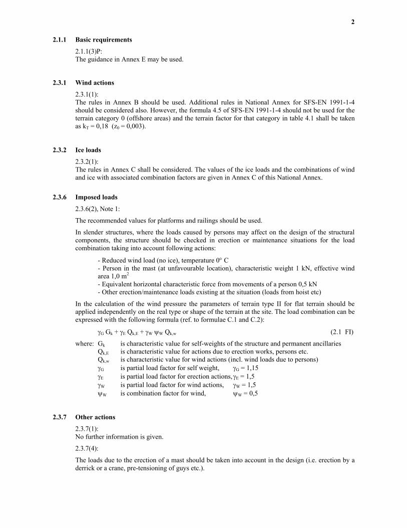
2.1.1 Basic requirements
2.1.1(3)P: The guidance in Annex E may be used.
2.3.1 Wind actions
2.3.1(1): The rules in Annex B should be used. Additional rules in National Annex for SFS-EN 1991-1-4 should be considered also. However, the formula 4.5 of SFS-EN 1991-1-4 should not be used for the terrain category 0 (offshore areas) and the terrain factor for that category in table 4.1 shall be taken as kT = 0,18 (z0 = 0,003).
2.3.2 Ice loads
2.3.2(1): The rules in Annex C shall be considered. The values of the ice loads and the combinations of wind and ice with associated combination factors are given in Annex C of this National Annex.
2.3.6 Imposed loads
2.3.6(2), Note 1:
The recommended values for platforms and railings should be used.
In slender structures, where the loads caused by persons may affect on the design of the structural components, the structure should be checked in erection or maintenance situations for the load combination taking into account following actions:
- Reduced wind load (no ice), temperature 0° C - Person in the mast (at unfavourable location), characteristic weight 1 kN, effective wind area 1,0 m2 - Equivalent horizontal characteristic force from movements of a person 0,5 kN - Other erection/maintenance loads existing at the situation (loads from hoist etc)
In the calculation of the wind pressure the parameters of terrain type II for flat terrain should be applied independently on the real type or shape of the terrain at the site. The load combination can be expressed with the following formula (ref. to formulae C.1 and C.2):
γG Gk + γE Qk,E + γW ψW Qk,w (2.1 FI)
where: Gk is characteristic value for self-weights of the structure and permanent ancillaries Qk,E is characteristic value for actions due to erection works, persons etc. Qk,w is characteristic value for wind actions (incl. wind loads due to persons) γG is partial load factor for self weight, γG = 1,15 γE is partial load factor for erection actions, γE = 1,5 γW is partial load factor for wind actions, γW = 1,5 ψW is combination factor for wind, ψW = 0,5
2.3.7 Other actions
2.3.7(1): No further information is given.
2.3.7(4):
The loads due to the erection of a mast should be taken into account in the design (i.e. erection by a derrick or a crane, pre-tensioning of guys etc.).

3
In the erection of a guyed mast, where any span between two adjacent guy levels is installed, the case where the guys at the upper guy level are not yet installed, should be checked. The load combination can be expressed with the following formula (ref. to formulae C.1 and C.2):
γG Gk + γW ψW Qk,w (2.2 FI)
where: Gk is characteristic value for self weights of the structure and ancillaries, Qk,w is characteristic value for wind actions, γG is partial load factor for self-weight, (see Table A.2) γW is partial load factor for wind actions, (see Table A.2) ψW is combination factor for wind, ψW = 0,4.
2.5 Design assisted by testing
2.5(1): No further information is given.
2.6 Durability
2.6(1): The recommended design life of important broadcasting and telecommunication towers and masts is 50 years. The design life of other towers and masts (i.e. structures for mobile network base stations or lightning towers etc.) is 30 years. The design lifetime should also be given in the Project Specification. The design lifetime for fatigue should be determined according to SFS-EN 1993-1-9 and its National Annex.
4.1 Allowance for corrosion
4.1(1), Note 1: See also SFS-EN ISO 10684 for galvanizing of bolts.
4.2 Guys
4.2(1): When assessing the need of possible protection measures, the design life of the structure should be taken into account. The change of the guys can be considered as an alternative instead of the protection methods recommended above.
5.1 Modelling for determining action effects
5.1(6): No further information is given.
5.2.4 Triangulated structures where continuity is taken into account (continuous or semi-continuous
framing)
5.2.4(1): No further information is given.
6.1 General
6.1(1), Note 1:
Following γM values should be used.
The resistance of the guy assembly (guy with end fittings) should be at least 90 % of the resistance of the straight guy. Mostly the decrease of the strength will be caused by the bending of the guy wire

4
around the fittings (wedge clamp or thimble).
γM0 = 1,00 γM1 = 1,00 γM2 = 1,25 γMg = 1,50 γMi = 2,00.
6.3.1 Compression members 6.3.1(1), Note 2: Either of the procedures a) or b) may be used.
6.4.1 General
6.4.1(1): The recommended values should be used. 6.4.2 Tension bolts in end plates (flanged connections)
6.4.2(2): No further information is given.
6.5.1 Mast base joint
6.5.1(1): No further information is given.
7 Serviceability limit states 7.1 Basis
7.1(1): The allowable values for the deformations should be defined in the Project Specification. The calculations should be done for reduced wind loads without ice, if other additional requirements are not specified in the Project Specification. If the patch load method is used in the design of a guyed mast, it should be applied also to the deformation analysis in the serviceability limit state.
The load combination can be expressed with the formula 7.1 FI (ref. to formulae C.1 and C.2), where
γG Gk + 0,64 γW Qk,w (7.1 FI)
where Gk is characteristic value for self weights of the structure and ancillaries Qk,w is characteristic value for wind actions γG is partial load factor for self weight, γG = 1,0 γW is partial load factor for wind actions, γW = 1,0.
For the partial safety factor of materials the recommended value for γM = 1,0 should be used. 9.5 Partial factors for fatigue
9.5(1): The recommended values according to the National Annex of SFS-EN 1993-1-9 should be used.

5
Annex A Reliability differentiation and partial factors for actions A.1 Reliability differentiation for masts and towers
A.1(1): The classes in Table A.1 (FI) should be used.
Table A.1 Reliability differentiation for towers and masts Reliability
Class
3 Towers and masts erected in urban locations, or where their failure is likely to cause injury or loss of life; towers and masts used for vital telecommunication facilities; other major structures where the consequences of failure would be likely to be very high
2 All towers and masts that cannot be defined as class 1 or 3
1 Towers and masts built on unmanned sites in open countryside; towers and masts, the failure of which would not be likely to cause injury to people
A.2 Partial factors for actions
A.2(1)P, Note 2:
The values of γG and γQ should be taken from the (revised) Table A.2 (FI).
Table A.2 (FI) Partial factors for permanent and variable actions
Type of effect Reliability class Permanent actions Variable actions 3 1,2 1,4 2 1,1 1,2 Unfavourable 1 1,0 1,1
Favourable All classes 1,0 0,0 Accidental situations 1,0 1,0
A.2(1)P, Note 3: No further information is given.
Annex B Modelling of meteorological actions Annex B may be used.
B.1.1(1): No further information is given for this clause (for ice loads, see Annex C). B.2.1.1(5): No further information is given.
B.2.3(1): Note 4 of Table B.2.1 and Note of Table B.2.2: The values of the coefficients in Tables B.2.1 and B.2.2 should be used.

6
B.3.2.2.6(4), Note 1: The recommended value of the coefficient KX =1,0 should be used. B.3.3(1): No further information is given.
B.3.3(2): No further information is given.
B.4.3.2.2(2), Note 2: The recommended value of the factor ks = 3,5 should be used. B.4.3.2.3(1), Note 2: The recommended value of the factor ks =3,5 should be used. B.4.3.2.8.1(4), Note 1: The recommended value of the coefficient KX = 1,0 should be used. Annex C Ice loading and combinations of ice with wind
Annex C may be used. C.2 Ice loading
C.2(1): The type of the ice on tower and mast structures in Finland is rime ice, see ISO 12494, clause 7.5.
The determination of the ice class at a certain height should be done by utilizing sufficiently long term icing statistics, which are possibly available from the site area. Co-operation with a meteorologist familiar with icing is recommended.
The mast structure should be divided vertically in sections with a maximum height of 100 m. The ice class will be defined for each section by using the height level at the 2/3 of the height of the section measured from the bottom of the section.
The ice class for a guy can be assumed to be constant on the whole length of the guy. The ice class is defined at a height of 2/3 of the height of the guy attachment level at the mast.
If no better information is available the following assumptions may be used:
- The ice class and the relevant ice weight on structural elements at a certain height are defined according to table Fi.C.2.1 in this NA. The values in the table are based on the ice density of 300 kg/m3 for the elements in the mast shaft and 400 kg/m3 for the guys.
- When calculating the thickness of the ice deposit on an element in a tower or mast for the determination of the effective wind area, the principles of ISO 12494 are recommended to be used. An alternative simplified method is given in clause C.6
For masts in reliability class 3 with ice class R6 or higher the eccentric ice in the shaft and asymmetrical icing of the guys should be considered. The centre of the eccentric shaft ice is assumed to be at a distance of 0,5 times the shaft width from the shaft centre in the most unfavourable direction in each load case for the structural element concerned. In the cases for asymmetrical icing of the guys, one or more guys can be without ice according to the Table Fi.C.2.3 in this NA.
The force coefficient for iced single elements and guys can be obtained from Tables 17 to 25 of ISO 12494 (see also Table B.2.1 in Annex B). The force coefficient of an iced lattice shaft is based on the solidity ratio of the mast faces according to annex B. The parameters concerning a lattice structure

7
composed of flat-sided elements should be used in all cases. The force coefficient for a lattice structure with all faces completely filled with ice depends on the ice class according to the Table C.2.2 (FI) in this NA.
The ice load of a fully iced lattice shaft is defined through the thickness of the ice deposit given in the Project Specification or calculated from the formula Fi.C.5 (value Ti,g) assuming symmetric icing.
Falling ice should be considered according to ISO 12494, Chapter 11.
Table C.2.1 (FI) Ice loads and k factors in different ice classes
Ice class H (m)
Gi (kg/m)
k
R1 0 - 50 0,5 0,40 R2 50 - 100 0,9 0,45 R3 100 - 150 1,6 0,50 R4 150 - 200 2,8 0,55 R5 200 - 250 5,0 0,60 R6 250 - 300 8,9 0,70 R7 300 - 350 16,0 0,80 R8 350 - 400 28,0 0,90 R9 400 - 450 50,0 1,00
H is the relative height from the average level of the surrounding terrain within the distance of 10 km from the site
Gi is the characteristic unit weight of the ice on the element k is the reduction factor in load combinations for wind and ice (see Clause C.6). piste
Table C.2.2 (FI) Force coefficient C f, S, 0, i for fully iced lattice shaft
Force coefficient for fully iced shaft C f, S, 0, i
Ice class
R1 - R3 2,0 1,8 R4 - R5 1,8 1,6 R6 - R7 1,6 1,4 R8 – R9 1,4 1,2
Wind drag is calculated to the area projected perpendicular to wind
Table C.2.3 (FI) Unsymmetrical ice loads for guys. N is the number of guy level.
Case Wind direction Guys without ice
Wind and guy directions
1 180 All guys of direction 1 2 0 All guys of directions 2 and 3 3 0 Guys of directions 2 and 3 in guy level 1
Na 0 1N , 2N-1 , 3N-1 Nb 0 1N , 2N-1 , 3N-1 , 2N+1 , 3N+1
Key: 2N-1 refers to guy in direction 2 in guy level N-1
2
3
1
θ wind

8
C.6 Combinations of ice and wind
C.6(1): The values for the reduction factor k defined in ISO 12494 are reviewed in Table Fi.C.2.1 in this NA. Following combination factors should be used in Finland:
ψw = 0,5 (C.3a FI) ψice = 0,3. (C.3b FI)
The wind area of an iced element or linear ancillary should be calculated using following design values for ice weight:
Gi,d = γice Gi in formula (C.1) (C.4a FI) Gi,d = γice ψice Gi in formula (C.2). (C.4b FI)
The ice thickness used in the calculation of the wind area of an element can be determined alternatively instead of methods in ISO 12494 using simplified methods with the formula Fi.C.5. The thickness of the ice deposit is assumed to be constant on each side of the element. Symbols:
Ti,s is the thickness of the ice deposit on an element or ancillary in the lattice structure Ti,g is the thickness of the ice deposit on a guy Gi,d is the design value of the ice weight (Gi will be taken from table C.2.1 FI) ρi is the density of the ice B is the width of the element or the diameter of the guy without ice.
The formula Fi.C.5 is valid for elements with B ≤ 300 mm. For larger elements and compact tubular shafts the ISO 12494 method for single elements should be used. The difference between the values Ti,g and Ti,s is due to the symmetric icing on the guy.
Temperatures in different load conditions:
- Reference condition (no wind, no ice) 0° C - Wind, no ice -20° C - Wind and ice (all combinations) 0° C.
The temperature should be taken into account, when determining the air density for the wind pressure.
Annex D Guys, dampers, insulators, ancillaries and other items
D.1.1(1): Rope safety clamps should not be used for the attachments of the guy ropes. D.1.2(2): No further information is given. D.3(6), Note 1: The breakage of a guy insulator shall not cause the collapse of the mast.
D.3(6), Note 2: No further information is given.
D.4.1(1): No further information is given.

9
D.4.2(3): The leg joints of the structure shall be provided with a good galvanic connection. The towers and masts should be equipped with a ground wire (minimum size 25 mm2 copper or 50 mm2 steel) from the top to the base of the structure. It shall be connected to the underground radial earthing net, which should fulfil the appropriate requirements of the authorities and the client.
D.4.3(1): The structure considered as an aviation obstruction should be painted with obstruction colours and/or equipped with obstruction lights according to requirements of ICAO and national aviation authority.
Details are given in the decision nr 1/2000 of the Finnish Civil Aviation Administration. The details on the markings can be found in the aviation regulation AGA M3-6.
D.4.4(1): No further information is given. Annex E Guy rupture Annex E may be used.
Annex F Fabrication and erection F.4.2.1(1): The recommended value should be used.
F.4.2.2(2): The recommended values should be used. Annex G Buckling of components of masts and towers
Annex G may be used.
G.1(3): The recommended values should be used. Annex H Buckling length and slenderness of members Annex H may be used.
H.2(5): No further information is given.
H.2(7), Note 2: No further information is given.

ANNEX 25
NATIONAL ANNEX
TO STANDARD
SFS-EN 1993-3-2 EUROCODE 3: DESIGN OF STEEL STRUCTURES. Part 3-2: Towers, masts and chimneys- Chimneys
Preface This national annex is used together with Standard SFS - EN 1993-3-2:2006.
This national annex sets out:
a) The national parameters for the following clauses in Standard SFS-EN 1993-3-2 where national
selection is permitted:
- 2.3.3.1(1) Note 1
- 2.3.3.5(1) Note 1
- 2.6(1)
- 4.2(1)
- 5.1(1)
- 6.1(1)
- 6.2.1 (6)
- 6.4.1(1)
- 6.4.2(1)
- 6.4.3(1) Note 1
- 7.2(1)
- 7.2(2) Note 2
- 9.1(3)
- 9.1(4)
- 9.5(1).
b) Guidance for the use of Annexes A, B, C, D and E .

2
2.3.3.1 Imposed loads
2.3.3.1(1), Note. 1: The recommended values should be used, if higher values are not required in the project. 2.3.3.5 Ice loads
2.3.3.5(1), Note 1: Ice loading should be determined based on the local conditions for each project. Combination factor ψ-should be determined according to the National Annex of the standard SFS-EN 1990 or SFS-EN 1993-3-1, as appropriate. 2.6 Durability
2.6(1): The design service life of the structure should be determined separately for each project. 4.2 External corrosion allowance
4.2(1): For coated structures the relevent standards should be used. Normal environment means classes C1, C2 or C3 according to SFS-EN 12944. 5.1 Modelling of chimneys for determining the effects of loads
5.1(1): Further information is not given in the National Annex. 6.1 General
6.1(1)P: The recommended values should be used. 6.2.1 Verification of strength
6.2.1(6): Further limits for the openings are not given in the National Annex. The recommended values should be used. In the fatigue loaded structures the distribution of the stresses mentioned above should be taken into account case by case. See also section 9 of the standard SFS-EN 1993-3-2. 6.4.1 General
6.4.1(1): The values given in the National Annex of the standard SFS-EN 1993-1-8 should be used. 6.4.2 Bolted connections for flanges 6.4.2(1): Further information is not given in the National Annex. 6.4.3 Connection of chimney to the foundation or supporting strucrure
6.4.3(1), Note 1: Further information is not given in the National Annex.

3
7.2 Deflections
7.2(1): The recommended value should be used. 7.2(2), Note 2: The recommended values should be used.
9.1 General
9.1(3): Further information is not given in the National Annex. 9.1(4): Further information is not given in the National Annex. The influence of the temperature should be taken into account case by case depending of the steel grade used. 9.5 Partial factors in respect of fatique
9.5(1): The values given in the National Annex of the standard SFS-EN 1993-1-9 should be used. Annex A: Reliability differentiation and partial factors for actions Annex A should be used. A.1(1): The reliability differentiation according to the table A.1 should be used.
A.2(1), Note 2: The values given in the table A.2 should be used.
A.2(1), Note 3: Further information is not given in the National Annex. Annex B and E of SFS-EN 1991-1-4 may be used together with their National Annexes. Annex B: Aerodynamic and damping measures Annex B should be used. Annex C: Fatique resistances and quality requirements Annex C should be used. C.2(1): Further information is not given in the National Annex. The use of higher fatigue classes than given in the standard SFS-EN 1993-1-9 should be based on reliable testing according to the Annex D of the standard SFS-EN 1990.

4
Annex D: Design assisted by testing Annex D should be used. Annex E: Implementation Annex E should be used.

ANNEX 26
NATIONAL ANNEX
TO
SFS-EN 1997-2 EUROCODE 7: GEOTECHNICAL DESIGN Part 2 – Ground survey and testing
This national annex is used together with Standard SFS-EN 1997-2:2007
CONTENTS Page
Contents 1
1. Foreword 2 2. Nationally determined parameters 2
Table 1. The use of CEN/TS –publications in Finland 3
Table 2 The use of informative annexes in Finland 4

2/(5)
NATIONAL ANNEX TO STANDARD
SFS-EN 1997-2:2007 GEOTECHNICAL DESIGN – PART 2 GROUND INVESTIGATION AND TESTING
1. Preface
This National Annex shall be used together with Standard SFS-EN 1997-2:2007. National choices in the Annex concern house building works and also associated excavation works and other foundation construction works. Standard SFS-EN 1997-2:2007 includes: - detailed rules concerning ground investigations, - general specifications concerning testing (determinations), - derivation procedures for soil characteristics and geotechnical model at
building site, - examples of calculation methods based on field and laboratory tests. National choices may be made regarding the use of the publications of CEN ISO/Technical Specifications (CEN ISO/TS) and the informative annexes set out in Standard SFS-EN 1997-2:2007.
2. National choices
In several paragraphs, Standard SFS-EN 1997-2:2007 refers to the publications of CEN ISO/Technical Specifications (CEN ISO/TS) used as supplementary material. The choices concerning the use of the said publications are set out in Table 1 of this National Annex. Standard SFS-EN 1997-2:2007 is accompanied by 24 informative annexes. The choices concerning the use of the said annexes are set out in Table 2 of this National Annex. Some of the CEN ISO/TS publications and informative annexes (or of their parts) may be approved for use as such. Whereas some of the said publications and annexes remain informative until they become Standards and are published. Informative publications and annexes may be used in Finland, as applicable, provided that the Finnish application rules, prepared for them, are taken into consideration. Guideline publications used in Finland and their application rules are set out in the publication: SFS Handbook 179-2 Geotechnical investigation and testing. Laboratory investigations of soil 2008.

3/(5)
TABLE 1. National Annex to SFS-EN 1997-2 Use of CEN ISO/TS publications in Finland ________________________________________________________________________ Item/CEN ISO/TS Adopted National rule to be used or application
as such rule for the adopted TS publication
________________________________________________________________________ 4.8.1(2)P, Note, CEN ISO/TS 22476-10:2004 Yes (Weight sounding) ________________________________________________________________________________________________ 4.10.1(4), Note, CEN ISO/TS 22476-11:2004 Yes (Flat dilatometer) ________________________________________________________________________________________________ 5.5.3.1(3), Note, CEN ISO/TS 17892-1:2004 Yes (Determination of water content) ________________________________________________________________________________________________ 5.5.4.1(3)P, Note, CEN ISO/TS 17892-2:2004 Yes (Determination of volume weight) ________________________________________________________________________________________________ 5.5.5.1(2)P, Note, CEN ISO/TS 17892-3:2004 No SFS Handbook 179-2. 2008 (Determination of solid density) ________________________________________________________________________________________________ 5.5.6.1(1), Note, CEN ISO/TS 17892-4:2004 No SFS Handbook 179-2. 2008 (Grain size analysis) ________________________________________________________________________________________________ 5.5.7.1(5), Note, CEN ISO/TS 17892-12:2004 No SFS Handbook 179-2. 2008 (Determination of consistency limits) ________________________________________________________________________________________________ 5.7.2(1)P, Note, CEN ISO/TS 17892-6:2004 No SFS Handbook 179-2. 2008 (Strength index tests of soil) ________________________________________________________________________________________________ 5.8.4.1(2), Note, CEN ISO/TS 17892-7:2004 Yes Note: Does not apply to stabilised soil. (Unconfined compression test) ________________________________________________________________________________________________ 5.8.5.1(3)P, Note, CEN ISO/TS 17892-8:2004 Yes (Unconsolidated closed triaxial test) ________________________________________________________________________________________________ 5.8.6.1(1)P, Note, CEN ISO/TS 17892-9:2004 No SFS Handbook 179-2. 2008 (Consolidated triaxial compression test) ________________________________________________________________________________________________ 5.8.7.1(1)P, Note, CEN ISO/TS 17892-10:2004 Yes (Consolidated direct box shear test) ________________________________________________________________________________________________ 5.9.2.2(7)P, Notes, CEN ISO/TS 17892-5:2004 No SFS Handbook 179-2. 2008 (Oedometer test) ________________________________________________________________________________________________ 5.11.2(1)P and 8, Notes, CEN ISO/TS 17892-11: No SFS Handbook 179-2. 2008 2004 (Water permeability test) ________________________________________________________________________________________________ 5.12.5.1(4), Note, Annexes U.4 and X.4.9.3 Yes (Determination of density and porosity) ________________________________________________________________________________________________ 5.12.5.2(3), Note, CEN ISO/TS 17892-3:2004 Yes (Determination of density and porosity) ________________________________________________________________________________________________

4/(5)
TABLE 2. National Annex to SFS-EN 1997-2 Use of informative annexes in Finland ________________________________________________________________________ Annex/subject Adopted as such National rule to be used or application rule
for the adopted Annex SFS-EN 1997-2 ________________________________________________________________________________________________ A List of investigation results of geotechnical test standards Yes ________________________________________________________________________________________________ B Planning of geotechnical investigations: - B.1 Stages of ground investigations Yes
- B.2 Choice of ground investigation methods Yes Geophysical methods other than seismic sounding, may also be approved for use.
- B.3 The spacings for survey points Yes When determining the spacings for survey points and the survey depths and the survey depths, the small scale of geological
formations in Finland is taken into account.
___________________________________________________________________________________________ C An example of derivation of groundwater pressure on the basis of a model and long-term Yes observations ________________________________________________________________________________________________ D CPT and CPTU tests Yes ________________________________________________________________________________________________ E Pressometer test Yes ________________________________________________________________________________________________ F SPT drilling Yes ________________________________________________________________________________________________ G Ram drilling Yes ________________________________________________________________________________________________ H Weight sounding Yes ________________________________________________________________________________________________ I Vane auger Yes ________________________________________________________________________________________________ J Dilatometer test DMT Yes ________________________________________________________________________________________________ K Plate loading test Yes ________________________________________________________________________________________________ L Preparation of soil sample for testing Yes ________________________________________________________________________________________________ M.1 Check list for classification tests Yes ________________________________________________________________________________________________ M.2 Determination of water content Yes ________________________________________________________________________________________________ M.3 Determination of volume weight Yes ________________________________________________________________________________________________ M.4 Determination of solid density No SFS Handbook 179-2. 2008 ________________________________________________________________________________________________M.5 Grain size analysis No SFS Handbook 179-2. 2008 ________________________________________________________________________________________________ M.6 Determination of relative density Yes ________________________________________________________________________________________________ M.7 Determination of dispersion of soil type Yes _______________________________________________________________________________________________M.8 Determination of frost susceptibility Yes

5/(5)
TABLE 2 continued ______________________________________________________________________________________ Annex/subject Adopted as such National rule to be used or application rule for the adopted Annex SFS-EN 1997-2 ________________________________________________________________________________________________ N Soil chemical tests Yes ________________________________________________________________________________________________ O Strength index tests of soil No SFS Handbook 179-2. 2008 P Strength tests of soil: - triaxial compression tests No SFS Handbook 179-2. 2008 - consolidated direct box shear tests Yes _______________________________________________________________________________________________Q Compressibility tests of soil No SFS Handbook 179-2. 2008 (oedometer test) _______________________________________________________________________________________________R Compaction tests of soil Yes ________________________________________________________________________________________________S Water permeability tests No SFS Handbook 179-2. 2008 of soil ________________________________________________________________________________________________T Preparation of rock samples Yes ________________________________________________________________________________________________U Classification tests of rock material Yes ________________________________________________________________________________________________V Expansion tests of rock material Yes ________________________________________________________________________________________________W Strength tests of rock Yes material ________________________________________________________________________________________________X Literature Informative use ________________________________________________________________________________________________


![EN 1993-2: Eurocode 3: Design of steel structures - Part 2 ... · PDF fileBS EN 1993-2:2006 EN 1993-2: 2006 (E) Foreword This European Standard EN ] 993-2, Eurocode 3: Design of steel](https://static.fdocuments.net/doc/165x107/5a9d3d837f8b9a032a8d0f93/en-1993-2-eurocode-3-design-of-steel-structures-part-2-en-1993-22006-en.jpg)


