National Aeronautics and Space Administration Chapter 3: Cube Satellite Systems Engineering...
34
•National Aeronautics and Space Administration •www.nasa.gov Chapter 3: Cube Satellite Systems Engineering Example
-
Upload
ambrose-weaver -
Category
Documents
-
view
229 -
download
0
Transcript of National Aeronautics and Space Administration Chapter 3: Cube Satellite Systems Engineering...
•National Aeronautics and Space Administration
•www.nasa.gov
Chapter 3: Cube Satellite Systems Engineering Example

Cube Satellite Structure
• The cube structure is an enclosed aluminum box with solar cells clamped on the outside walls. Antennas are deployed perpendicular to the faces at the corners. Internals include sensors, a camera and printed circuit boards.
•
10 cm
Solar cells
Aluminum Frame

A Systems Engineering Example
• The Systems Engineering process is demonstrated on a Cubic Satellite (CubeSat) named the AS-1.
• This is a multidisciplinary project, with each subsystem being designed by a team of a particular discipline suited to that subsystem.
• The full report (AUSSP, 2007) describes the design of cubesat AS-1, and can be found at http://space.auburn.edu/page_attachments/0000/0046/Spring_2008.pdf
• The eleven SE functions are applied in each phase, the five around the triangle and the other SE functions.
• SE tools (e.g. block diagrams, budgeting (e.g. mass, power and link), trade studies, and failure mode analysis) are introduced and demonstrated where the tool is warranted.
Mission Information
• Pre-imposed design requirements (http://cubesat.org/) include a 10 cm cube, 1 kg mass limitation
• The mission objective for this student team is to test in space a GaN-based Ultraviolet (UV) photodetector. The student team was tasked to design, build and operate the CubeSat in Low Earth Orbit (LEO) carrying the photodetector as the payload.
• The satellite will be deployed using the standard Poly Picosatellite Orbital Deployer (P-POD). The orbit is 700 km altitude (Low Earth Orbit), sun-synchronous, near-polar, 98° inclination orbit, orbital period: +/- 98 minutes, with 3-5, 10-14 minute communications windows/day, with low power and low data rate.
• Design for launch on a Russian Dnepr Rocket• Currently in Phase B: Preliminary Design and Technology Completion.

Management Structure
• Subsystems: Payload, C&DH (Command and Data Handling), COMM (Communications), EPS (Electrical Power System), ADC (Attitude Determination and Control), Structures and Mechanisms, Thermal Control and Ground Station.
Management Structure• The program manager is in this case the faculty advisor. • The project manager is responsible for scheduling the development cycle,
defining mission requirements and goals, as well as the overall success of the project. He is also responsible for keeping the project costs within budget.
• The systems engineer is responsible for guiding the engineering of the project; for defining, verifying and validating system requirements’ flow down to each subsystem; and for the integration and test phases of the project. He/she is also responsible for coordinating system trade studies, managing critical resources/interfaces for each subsystem and failure mode and risk analysis.
• Each subsystem leader is responsible for the development and testing of their individual subsystem, and must remain aware of how changes in their subsystem affect other subsystems and the system as a whole. The subsystem leads were selected in anticipation of the probable subsystems.

Team Responsibilities
• Systems Engineering Team – Analyzes the characteristics of the mission such as orbit and environment. Ensure all subsystems interface properly and work as one fully integrated satellite. They also guide the engineering of the satellite, ensuring that all mission requirements are met, while bridging the various engineering disciplines. They manages mass and volume budget and oversees all other budgets.
• Ground Station Team – Designs, builds, and operates ground station antennas, mounting, enclosure, and computer. Selects and installs operating programs and data processing. Handles communication with AS-1 and tracking of other amateur satellites.
• Communications Team – Designs, builds, tests the communication system including: antennas, transceivers and TNCs. Manages the link budget.
• Attitude Determination and Control Team– Designs, builds and tests the ADC subsystem to for solar cell orientation to the sun for the EPS and antenna orientation for communication, and includes magnets, hysteresis dampeners, attitude determination algorithm design based on solar cell orientation.

Team Responsibilities
• Command and Data Handling Team – Designs the Command and Data architecture. Selects hardware components, designs circuit board layout and programs the processor. Selects sensors and incorporates them into the design. Manages the data budget.
• Electrical Power System Team – Designs, builds and tests the power subsystem, including solar cells, rechargeable batteries and power regulators. Manages the power budget.
• Structures Team - Designs and builds the structure of the satellite including the mounting for all components, fulfilling compliance with CubeSat specs and system requirements, including launch vibration.
• Thermal Team – Conducts the steady-state and transient thermal analysis of both the internal and external structure to ensure component thermal requirements are met.
• Payload Team – Develops hardware components needed to accompany payload and ensures the design meets requirements set by the scientists.
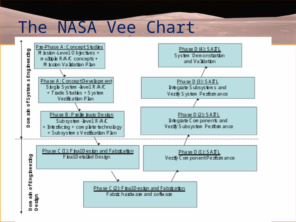
The NASA Vee Chart

11 System Engineering Functions

Pre-Phase A: Concept Studies
Purpose: produce a broad spectrum of ideas and alternatives (i.e. concepts) for the mission architecture, mission requirements, and mission operation.
Systems Engineer’s Tasks: Leads all Pre-phase A activities with support from subsystems lead personnel.
Eleven SE Functions
1. Mission Objective: Determine if a small satellite platform and Ultraviolet photodetector sensor (the payload) can be designed, built and operated by a team of university students
2. Architecture and Design Development (at right) In most cases there will be more than one architecture, but this team was constrained by the CubeSat requirements.
Cubesat System
CubeSat Satellite
Ground Station
Rocket + P-Pod
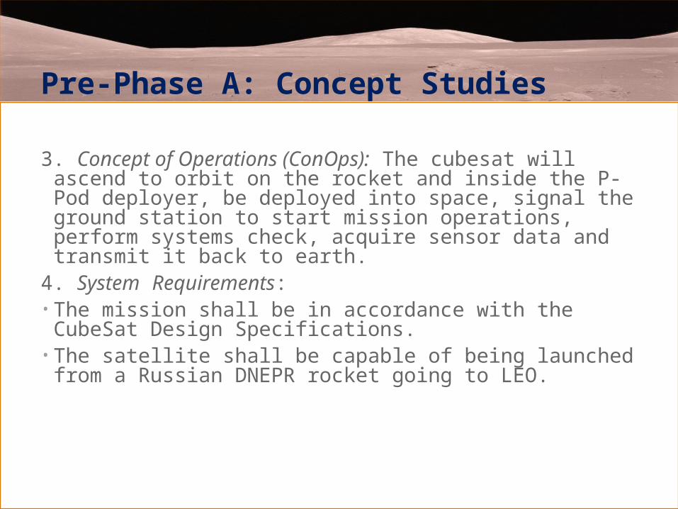
Pre-Phase A: Concept Studies
3. Concept of Operations (ConOps): The cubesat will ascend to orbit on the rocket and inside the P-Pod deployer, be deployed into space, signal the ground station to start mission operations, perform systems check, acquire sensor data and transmit it back to earth.
4. System Requirements: • The mission shall be in accordance with the CubeSat
Design Specifications. • The satellite shall be capable of being launched from a
Russian DNEPR rocket going to LEO.

Pre-Phase A: Concept Studies
5. Validation Plan: In Phase D, the cubesat system will be validated by performing a dry run mission on earth, beginning with a mock deployment from a P-Pod, and with the ground station as operations center.
• Interfaces: The payload (GaN sensor) is interfaced to the satellite. The satellite sends data wirelessly to the ground station. A deployer (P-Pod) on the rocket will store and then launch the cubesat.

Pre-Phase A: Concept Studies
7. Mission Environment: At 650 – 800 km altitudethe temperature ranges between 750 and 1000K, but the low density means there is essentially no heat capacity, and no conductive heat transfer. Atomic oxygen exists because its bonds are easily broken by the incident UV radiation. In the vacuum, tin-plated parts may whisker causing short circuits. The suggested mitigation is a conformal coating…….
11. Mission Concept Review

Phase A – Concept and Technology Development
Purpose:
Determine the feasibility and desirability of a system and establish a single approach and baseline system architecture.
Focus on the system level requirements and a system level architecture. Here the team drives down the mission requirements to detailed system specification requirements, such as power voltage levels (i.e. 28 VDC +/- .5 V).
Trade studies are performed to determine the best system for the project; consider the key parameters, i.e. power consumption, weight, volume, space legacy, costs, etc. to choose the best approach.
Propose the subsystems and anticipated performance of each, identify major components of the subsystems. If necessary apply modeling techniques such as engineering modeling, state machines, block diagrams, computer simulations, proof-of-concept prototypes, mental models, or strawman designs to compare alternative architectures to home-in on the best.
Identify risks and perform necessary analyses. System requirements, specifications and schematics are released in formal documents. Subsystem budgets are allocated and controlled.

Phase A – Concept and Technology Development
3. Architecture and Design – including subsystem function (e.g. a communications system will be needed to send signals from the satellite to the ground station.
CubeSatellite System
CubeSatellite
GroundStation
RocketSystem
Payload C&DH COMM EPS ACDThermalStructures
and Mechanisms
Tier 1 Systems:
Tier 2 Systems:
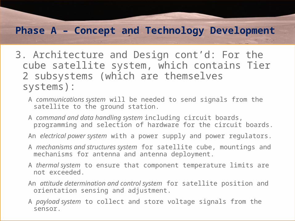
Phase A – Concept and Technology Development
3. Architecture and Design cont’d: For the cube satellite system, which contains Tier 2 subsystems (which are themselves systems):
A communications system will be needed to send signals from the satellite to the ground station.
A command and data handling system including circuit boards, programming and selection of hardware for the circuit boards.
An electrical power system with a power supply and power regulators.
A mechanisms and structures system for satellite cube, mountings and mechanisms for antenna and antenna deployment.
A thermal system to ensure that component temperature limits are not exceeded.
An attitude determination and control system for satellite position and orientation sensing and adjustment.
A payload system to collect and store voltage signals from the sensor.

Phase A – Concept and Technology Development
3. Architecture and Design cont’d: C&DH team conducted a trade study to compare two possible controllers (see Chapter 4 for details on conducting a trade study)

Phase A – Concept and Technology Development
4. Concept of Operations• Launch sequence – This is a one time “sequence” preformed after launch. Once
this sequence is performed the satellite will only operate in one of the four modes of operation (safe, idle, normal, and transmit).
• Safe mode – C&DH is on and ready to go into idle mode. Perform basic tasks, such as battery charging, checking vital housekeeping.
• Idle mode – Only housekeeping electronics are on. C&DH is storing housekeeping information. Batteries will also be charging if need be. Check transmitting beacon.
• Normal mode – Science experiment running, C&DH will be storing data from experiment. C&DH is collecting housekeeping data. Battery charging. Transmitting beacon.
• Transmit mode – retrieve and transmit stored data, transmitting beacon, upload data (transmitter shutdown, etc).

Phase A – Concept and Technology Development
2. Derived Requirements (system requirements)• The spacecraft must be capable of being launched from a Russian requirement
going to LEO following cubesat calpoly PPOD depolyer and cubesat design requirements.
• AS-Ia shall be designed for low earth orbit (LEO), 600-800km, 98° inclination• AS-Ia shall conform to FCC regulations• AS-I shall not exceed a mass of 1kg• AS-Ia shall have no electronics active during launch• AS-Ia shall be capable of surviving the transit, pre-launch, launch, and space
environments.• Full system and subsystem level documentation shall be provided prior to integration
of AS-Ia• AS-Ia shall conform to all CalPoly constraints and requirements.

Phase A – Concept and Technology Development
6. Interfaces: C&DH interfaces to all systems, Power additionally interfaces to COMM, COMM interfaces to Ground Station, and payload interfaces to C&DH.
7.-11. Other SE functions: Document results of the systems engineering functions in a report and present at MDR (Mission Definition Review). Documents updated in the electronic library should include the ConOps, Architecture and Design, Requirements, Resources Budgets, System Verification Plan. Start the Interface Control Document (ICD).

Phase B - Preliminary Design and Technology Completion
• Purpose: To define the project in enough detail to establish a single initial “baseline design”. The focus shifts to the subsystems (Requirements, ConOp and Architecture/design) and their interfacing. Subsystem engineering teams are heavily involved defining their subsystems and components; subsystem design concepts are developed and all high-risk areas resolved (i.e. technology completion).

Phase B - Preliminary Design and Technology Completion
• Continue internal/external interface control and update ICD.• Continue to control system budgets and now subsystem budgets also.• Assure that subsystem design concepts are within and compatible with
system requirements. Update system requirements if necessary. Always keep the mission objectives and requirements in mind throughout the process.
• Complete all system level trades and update. Assure that subsystem trades are done.
• If necessary model the system using techniques such as analytical modeling, state machines, block diagrams, computer simulations, CAD, mock-ups, proof-of-concept prototypes and mental models to compare alternative designs and architectures of subsystems and to resolve high risk areas. Build demonstrational prototype(s) if needed for validation and technology completion (i.e. technology that needs to be proven before going onto Phase C and the detailed design tasks).
• Approve the ICD, trade studies and risk identification/mitigation plans.
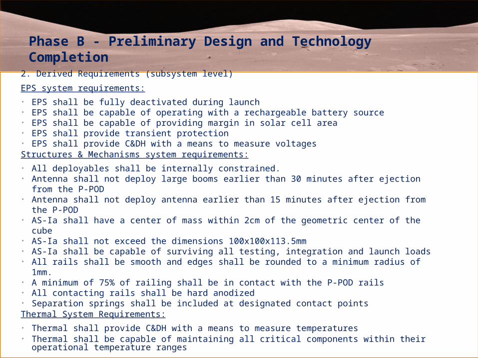
Phase B - Preliminary Design and Technology Completion
2. Derived Requirements (subsystem level)
EPS system requirements:
• EPS shall be fully deactivated during launch• EPS shall be capable of operating with a rechargeable battery source• EPS shall be capable of providing margin in solar cell area• EPS shall provide transient protection• EPS shall provide C&DH with a means to measure voltagesStructures & Mechanisms system requirements:
• All deployables shall be internally constrained.• Antenna shall not deploy large booms earlier than 30 minutes after ejection from the P-POD• Antenna shall not deploy antenna earlier than 15 minutes after ejection from the P-POD• AS-Ia shall have a center of mass within 2cm of the geometric center of the cube• AS-Ia shall not exceed the dimensions 100x100x113.5mm• AS-Ia shall be capable of surviving all testing, integration and launch loads• All rails shall be smooth and edges shall be rounded to a minimum radius of 1mm.• A minimum of 75% of railing shall be in contact with the P-POD rails• All contacting rails shall be hard anodized• Separation springs shall be included at designated contact pointsThermal System Requirements:
• Thermal shall provide C&DH with a means to measure temperatures• Thermal shall be capable of maintaining all critical components within their operational temperature
ranges
Phase B - Preliminary Design and Technology Completion
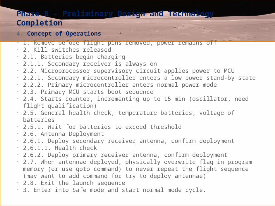
4. Concept of Operations
• 1. Remove before flight pins removed, power remains off• 2. Kill switches released• 2.1. Batteries begin charging• 2.1.1. Secondary receiver is always on• 2.2. Microprocessor supervisory circuit applies power to MCU• 2.2.1. Secondary microcontroller enters a low power stand-by state• 2.2.2. Primary microcontroller enters normal power mode• 2.3. Primary MCU starts boot sequence• 2.4. Starts counter, incrementing up to 15 min (oscillator, need flight qualification)• 2.5. General health check, temperature batteries, voltage of batteries• 2.5.1. Wait for batteries to exceed threshold• 2.6. Antenna Deployment• 2.6.1. Deploy secondary receiver antenna, confirm deployment• 2.6.1.1. Health check• 2.6.2. Deploy primary receiver antenna, confirm deployment• 2.7. When antennae deployed, physically overwrite flag in program memory (or use
goto command) to never repeat the flight sequence (may want to add command for try to deploy antennae)
• 2.8. Exit the launch sequence• 3. Enter into Safe mode and start normal mode cycle.

Phase B - Preliminary Design and Technology Completion3. Architecture and Design• Payload• GaN based UV sensor• C&DH (Command and Data Handling)• Redundant Atmel ATmega2561 Microcontroller• I2C, SPI, & USART serial bus protocols (peripherals)• 32MB Atmel external serial flash memory• Dual-coil latching relay power control• COMM (Communications)• 1) 435 – 438 MHz uplink/downlink,2) 1200 baud FM modulation, 3) Yaesu VX-2R 2 W
Transceiver,4) \TNC-X ,5) 2 Half Wave Dipole Antenna• EPS (Electrical Power System)• 1) 4 – 6 strings of 2 each series 26.8% efficient ITJ Spectrolab CICs, 2) 1.8W input from solar
cells, single side, 3) MAX1879 MPPT/Battery charging chip, 4) Two rechargeable Ultralife 1.7Ah, 3.7 V Li-Ion batteries.
• ACD (Attitude & Control Determination)• 1) Control: Alinco Cast 5 permanent magnets & Hysteresis dampening, 2) Determination:
Solar cells used as cosine detectors• Structures and Mechanisms• ~100mm x 100mm x 113.5mm “cube” shell, created with hard-anodized Al 7075 T6, less than
1kg total mass, including support for PCB boards and all internal components.• Ground Station 1) 117” M2 yagi antenna, 14.15 dBdc gain, 2) Computer-controlled Yaesu G-
5500 AZ-EL antenna rotator, 3) ICOM 910-H transceiver, 4) Kantronics KPC3+ TNC, 5) Nova for Windows tracking software, 5) Ham Radio Deluxe transceiver control software, 6)UI-View communications software

Phase B - Preliminary Design and Technology Completion
4. Architecture and Design – Product Breakdown Structure

Phase B - Preliminary Design and Technology Completion, C&DH parts list for subsystem prototype testing
Phase B - Preliminary Design and Technology Completion
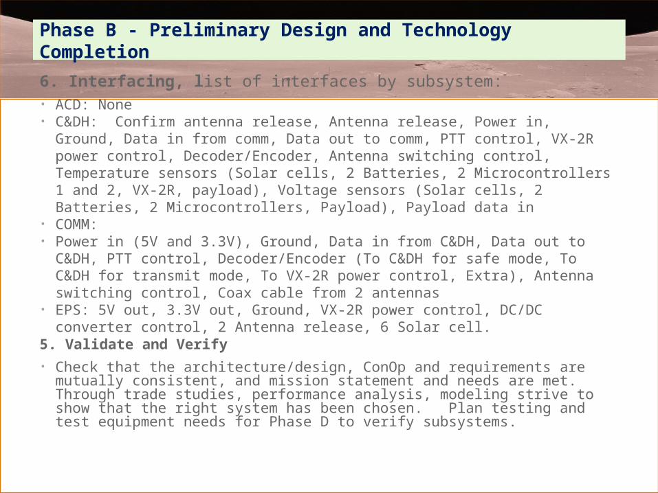
6. Interfacing, list of interfaces by subsystem:• ACD: None• C&DH: Confirm antenna release, Antenna release, Power in, Ground, Data in from
comm, Data out to comm, PTT control, VX-2R power control, Decoder/Encoder, Antenna switching control, Temperature sensors (Solar cells, 2 Batteries, 2 Microcontrollers 1 and 2, VX-2R, payload), Voltage sensors (Solar cells, 2 Batteries, 2 Microcontrollers, Payload), Payload data in
• COMM:• Power in (5V and 3.3V), Ground, Data in from C&DH, Data out to C&DH, PTT control,
Decoder/Encoder (To C&DH for safe mode, To C&DH for transmit mode, To VX-2R power control, Extra), Antenna switching control, Coax cable from 2 antennas
• EPS: 5V out, 3.3V out, Ground, VX-2R power control, DC/DC converter control, 2 Antenna release, 6 Solar cell.
5. Validate and Verify
• Check that the architecture/design, ConOp and requirements are mutually consistent, and mission statement and needs are met. Through trade studies, performance analysis, modeling strive to show that the right system has been chosen. Plan testing and test equipment needs for Phase D to verify subsystems.
Phase B - Preliminary Design and Technology Completion
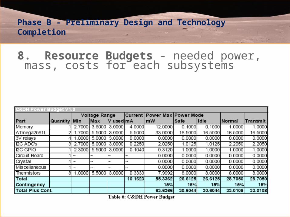
8. Resource Budgets - needed power, mass, costs for each subsystems

Phase B - Preliminary Design and Technology Completion
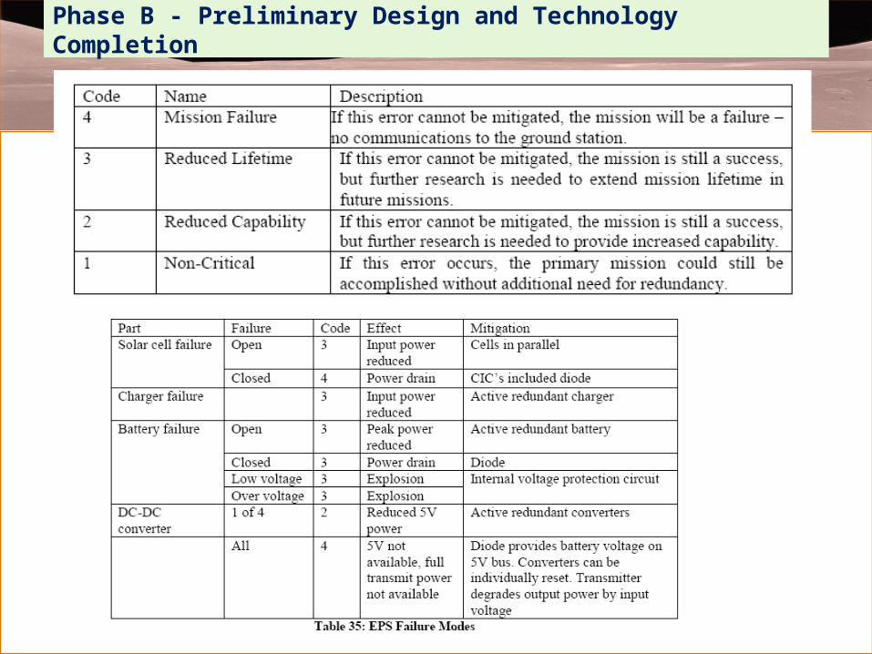
9. Risk Management
Failure Modes Analysis for risk mitigation as performed on the EPS System is presented below. Because AS-I does not have the funds or the available space to mitigate every potential failure, the system must be redundant, fault tolerant, and able to correct detected errors. Failure Modes Analysis is done to determine what the potential failures are in the satellite design and how to mitigate them. This analysis determines the relation between the failure of a single component and its effects on the system as a whole. We accept that no system is perfect, and so some risks are acceptable. Mitigation attempts will be focused on those failures which might cause mission failure. In most cases a duplicate component can be used to mitigate any mission failure. The following table shows the four different ways a component failure can affect the whole system.
A single point failure occurs if the mission fails as a result of a single component on the satellite failing. These should be identified and mitigated.
Phase B - Preliminary Design and Technology Completion

Phase B - Preliminary Design and Technology Completion
11. Reviews – Preliminary Design Review (PDR)
Onto Phase C……