NaSPUoN Report March2021 - civil.uonbi.ac.ke
18
Page 1 of 18 KSA – UoN NanoSatellite Research Chair - NaSPUoN Development Update Report - March 2021 BY NanoSatellite Platform for the University of Nairobi (NaSPUoN) Team: Principal Investigator: Eng. Prof. Mwangi Mbuthia Department of Electrical & Information Engineering Project Manager: Dr. Mutugi Kiruki Formerly of Kyushu Institute of Technology, Japan Staff: Ms. Betsy Mugo Department of Geospatial and Space Technology Students: Department of Electrical & Information Engineering 1. June Akinyi – 5 th year 2. Alvyne Mwaniki – 4 th year 3. Chebet Kamara – 4 th year 4. Alex Gichamba – 3 rd year 5. Ben Tito – 3 rd year Department of Mechanical & Manufacturing Engineering 6. Chand Hirani - 4 th year 7. Duncan Kariuki – 4 th year 8. Sonny Munene – 4 th year Department of Geospatial & Space Technology 9. Christine Nyakinyua – 4 th year 10. Brian Musyoki – 3 rd year 11. Veronica Akinyi – 4 th year
Transcript of NaSPUoN Report March2021 - civil.uonbi.ac.ke

Page1of18
KSA – UoN NanoSatellite Research Chair - NaSPUoN Development Update Report - March 2021
BY
NanoSatellite Platform for the University of Nairobi (NaSPUoN) Team:
Principal Investigator: Eng. Prof. Mwangi Mbuthia Department of Electrical & Information Engineering
Project Manager: Dr. Mutugi Kiruki Formerly of Kyushu Institute of Technology, Japan
Staff: Ms. Betsy Mugo Department of Geospatial and Space Technology
Students: Department of Electrical & Information Engineering
1. June Akinyi – 5th year 2. Alvyne Mwaniki – 4th year 3. Chebet Kamara – 4th year 4. Alex Gichamba – 3rd year 5. Ben Tito – 3rd year
Department of Mechanical & Manufacturing Engineering
6. Chand Hirani - 4th year 7. Duncan Kariuki – 4th year 8. Sonny Munene – 4th year
Department of Geospatial & Space Technology
9. Christine Nyakinyua – 4th year 10. Brian Musyoki – 3rd year 11. Veronica Akinyi – 4th year

Page2of18
Summary
The team commenced on the NaSPUoN project in October, holding the kick-off meeting on 6th October 2020. The team has been holding weekly meetings since then, except for the Christmas period (17th Dec to 5th Jan) and the end of semester examinations period (13th Feb to 28th Feb 2021). Since the beginning of the project, the meetings have been held virtually since the students had been working from home. However, from March the students had begun hands-on work in the laboratory at UoN. This has however been cut short by the closure of the university on 27th March due to the 3rd wave of Covid-19. The project commenced with students conducting literature review and research on nanosatellites and CubeSat technology. They were also introduced to various software tools that they would use during the project. These are mainly for PCB design and 3D CAD modeling. The students were also guided in researching on the two missions for NaSPUoN, i.e., Camera and LoRa mission. This was conducted in the first two months of the project, where they also identified the parts and components required for the realization of the NaSPUoN model. Initially there were 7 students working on the project. However, after evaluation of the workload and the less than 6 months for delivery, it was found necessary to increase the number of students to 11. They are drawn from the 3 engineering departments at UoN i.e., Electrical, Mechanical and Geospatial Engineering. Within 3 months, the team had come up with a high-level system design of NaSPUoN, both at mission and subsystem levels. With this design, components and modules necessary for implementation were analyzed and chosen. A comprehensive list of all the items required for the full realization of the project was prepared within the available budget. As a result, various design decisions were made to ensure that the project is within the budget. Hence, the NaSPUoN bench model will be operationally and structurally different from a standard 1U CubeSat. On 16th December 2020, the team organized a public seminar in accordance with the KSA grant requirements. There was both physical and online attendance, with the venue being at the University of Nairobi Towers. The students made presentations on their various missions and subsystems. The seminar was open to all UoN students and staff, and the public. On 10th March, the team made an online presentation to KSA, updating them on the progress. Another update to KSA is scheduled for 8th April. There was a significant delay in the procurement of project components and items. This is due to the new and stringent procurement process at the university which resulted in the whole process taking longer than anticipated. This is one of the project challenges, as the 6-month window requires a fast turnaround in components ordering and acquisition. Another challenge is the closure of the university on 27th March 2021 due to 3rd wave of Covid-19. This has curtailed hands-on work at the laboratory. This will adversely affect the integration phase of the project since most of the remaining work needs physical access to the laboratories.
The following sections present brief updates on the various project teams and subsystems.

Page3of18
1. Camera Mission
Introduction
Earth Observation (EO) and remote sensing is a fundamental goal on many satellite missions. Remote sensing is the art and science of acquiring information about the earth’s surface without necessarily being in direct contact with it and this can be achieved by sensors.
These sensors can be active sensor systems which emit their own energy to the target and measure the amount of radiation that is reflected or backscattered from the target e.g Lidar and Radar or passive sensor systems which rely on an external source of energy such as the sun to detect the amount of radiation emitted or reflected from the target e.g those used in film photography and radiometers. Sensors operating in the visible spectrum i.e. cameras are widespread partly due to their low cost and power budgets as well as the easy interpretation of their data output (images).
Several organizations provide satellite Earth Observation solutions in Kenya and they include the Survey of Kenya, Geomaps Africa, Oakar Services, Regional Centre for Mapping of Resources for Development. Classification of this imagery is done regarding:
• Spatial resolution which is the smallest size of a feature that the sensor can detect. • Spectral resolution which specifies the spectral bands in which the sensor can detect
reflected radiance. • Temporal resolution which specifies the revisiting frequency of a satellite sensor for a
specific location. • Radiometric resolution which refers to how much information is in a pixel and is
expressed in units of bits.
Satellite imageries have a wide range of applications such as in meteorology, agriculture, extracting mineral deposits, disaster mitigation and recovery, land use land cover and change detection.
NaSPUoN Camera Mission
CubeSats can be used for educational projects whereby the students obtain unique hands-on experience in developing space missions, technology demonstration as well as commercial applications. CubeSats allow for direct data downlink to various small ground station, are highly accessible due to their low cost of development, don't weigh that much and use simple technology.
For small satellites such as CubeSats, the quality of images captured is comprised due to the limitation of the size of cameras that can be accommodated.
The proposal in regard to NaSPUoN is to investigate the incorporation of a lens (at least 35mm in length) to the camera and to determine the appropriate mounting approach that best utilizes the limited space available in the 1U CubeSat which has least impact on other subsystems and missions onboard the satellite.
The cameras investigated for this project are the Arducam 5MP Mini Camera, USB 3MP Camera and Raspberry Pi High Quality Camera. The camera chosen is the Raspberry Pi High Quality Camera.
Page4of18
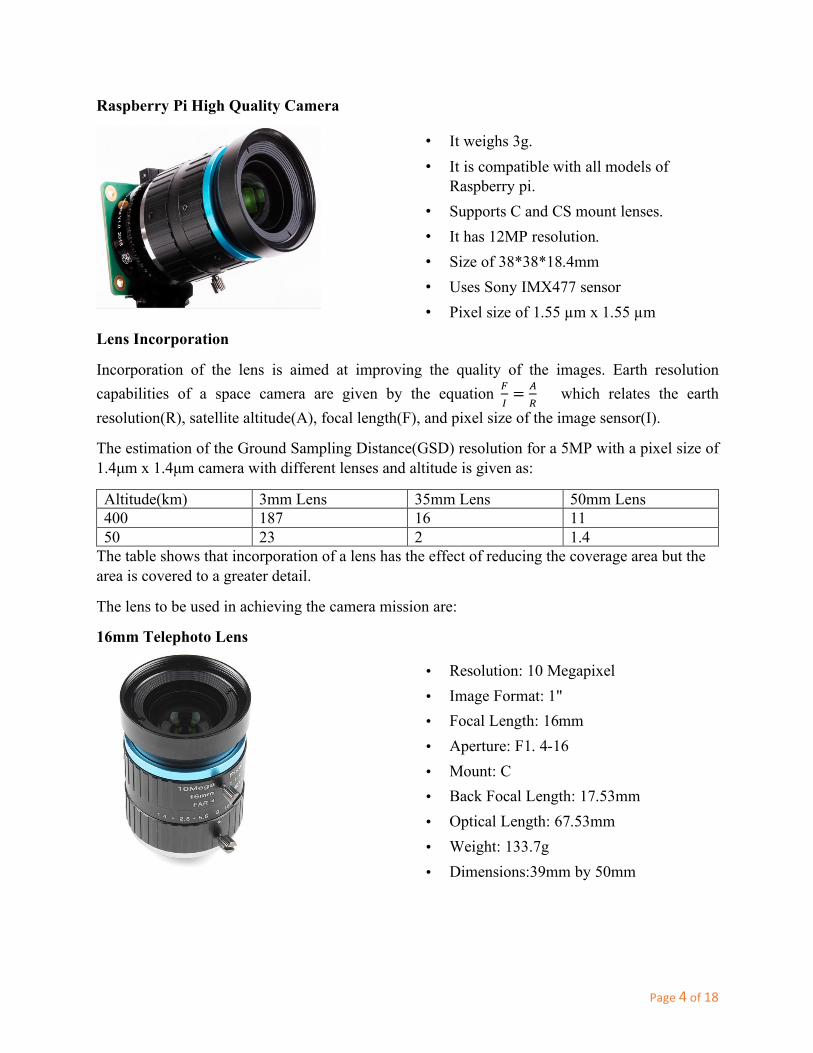
Raspberry Pi High Quality Camera
Lens Incorporation
Incorporation of the lens is aimed at improving the quality of the images. Earth resolution capabilities of a space camera are given by the equation !
"= $
% which relates the earth
resolution(R), satellite altitude(A), focal length(F), and pixel size of the image sensor(I).
The estimation of the Ground Sampling Distance(GSD) resolution for a 5MP with a pixel size of 1.4µm x 1.4µm camera with different lenses and altitude is given as:
Altitude(km) 3mm Lens 35mm Lens 50mm Lens 400 187 16 11 50 23 2 1.4
The table shows that incorporation of a lens has the effect of reducing the coverage area but the area is covered to a greater detail.
The lens to be used in achieving the camera mission are:
16mm Telephoto Lens
• It weighs 3g. • It is compatible with all models of
Raspberry pi. • Supports C and CS mount lenses. • It has 12MP resolution. • Size of 38*38*18.4mm • Uses Sony IMX477 sensor • Pixel size of 1.55 µm x 1.55 µm
• Resolution: 10 Megapixel • Image Format: 1" • Focal Length: 16mm • Aperture: F1. 4-16 • Mount: C • Back Focal Length: 17.53mm • Optical Length: 67.53mm • Weight: 133.7g • Dimensions:39mm by 50mm

Page5of18
The mounting technique to be used is such that the adapter board at the top will be used by the camera and the LoRa mission without interfering with other subsystems. The camera and LoRa module will share a board whereby the camera and sensor will be on the top part while the LoRa will be on the bottom part.
The Figures below show the design of the Camera+LoRa adapter board. The schematic has been done on Eagle PCB whilst the CAD model has been designed using Solidworks.
• Model No: C1535ZM01 • Optical Format: 2/3″ • Focal Length: 35mm • Aperture: F1.7 ~ F16, adjustable • Focus Type: manual • Mount: C mount • Back Focal Length: 17.53mm • Dimension: 35×30mm • Weight: 75.5g
35mm Arducam Lens

Page6of18
2. LoRa Mission
LoRa (short for Long Range) is a communication technology designed to provide long range connectivity to battery operated devices. The utilization of LoRa in this project addresses the need for energy and cost-effective remote data collection. The LoRa team is also responsible for the temperature sensor and inertial measurement unit in this project. These sensors will enable the collection of relevant housekeeping data to ensure the success of the nanosatellite.
Modules in use
The LoRa team finalized on the selection of modules for this mission. The choice for the selected modules was driven by the specific requirements for each task. The modules to be used are:
1) Dragino LoRa/GPS HAT – LoRa and GPS module 2) Adafruit ICM20948 – Inertial Measurement Unit 3) Adafruit MCP9808 – Temperature Sensor
1) LoRa/GPS HAT
The LoRa/GPS HAT from Dragino is the LoRa module in use. In addition, it will provide positioning data as it has GPS. It utilizes 868/433/915 MHz frequencies, which can be regulated to the standard frequency. The LoRa module will use SPI to interface with the OBC, while GPS will use UART.
2) ICM20948 Inertial Measurement Unit
The ICM20948 will be the Inertial Measurement Unit used. It has a 9-DOF gyroscope, accelerometer, and magnetometer. It will provide data on the orientation of the nanosatellite, as well as the acceleration and magnetic forces acting on it. It will use I2C to interface with the OBC.

Page7of18
3) MCP9808 Temperature sensor
The MCP9808 temperature sensor will provide the data on ambient temperature of the nanosatellite. It will also use I2C to interface with the OBC.
Design
The LoRa module and sensors will share an adapter board on the nanosatellite with the camera. This will be the board that will be right at the top to allow the camera to capture images without any obstruction. To enable the components to fit on the 86mm. by 86mm. adapter board, the decision was made to have the LoRa module on the bottom side, while the camera and the sensors will be positioned on the top side.
The team is finalizing on the board design. Autodesk Eagle is the software being used for this design stage. The figure below shows part of the schematic and PCB design progress:

Page8of18
3. Onboard Computer (OBC) and Communication Subsystem
Components Selection (OBC)
The initial design choice was to use a Raspberry Pi 4 for the on-board computer. However, mainly due to size restrictions in the 1U CubeSat specification, the Raspberry Pi Zero was the component that was settled upon. Even though the Raspberry Pi Zero is less computationally powerful and has less interfaces compared to the Raspberry Pi 4.
The specifications of the Raspberry Pi Zero are as follows:
ü Single-core BCM2835 at 1GHz ü 512MB RAM ü Small Size ü Typical Power draw of 0.75W – this is lower than
that of the Raspberry Pi 4 ü Can be powered using the GPIO header – the
Raspberry Pi 4 cannot ü Interfaces available:
Ø 1 UART *{there are 2 UART’s but only one can be used at a time since they are on the same pins}
Ø 2 SPI buses (total of 5 CS pins) Ø 1 I2C bus *{2 I2C’s but only one is usable the other being a special-purpose I2C}
Components and routing on the top Components and routing on the bottom
Figure Error! No text of specified style in document..1: Raspberry Pi Zero

Page9of18
Ø 1 CSI header (only on Raspberry Pi v1.3)
Components Selection (COMMS)
The communication subsystem was chosen to be the only subsystem that will be as close to space-grade as possible, since it is an essential platform. Therefore, the StenSAT radio beacon was selected to be NaSPUoN’s space-grade transmitter.
The specifications of the StenSAT Radio Beacon (STM-51-02C) are as follows: ü Frequency Range: 420-450 MHz ü Output Power: 0-3 W (Programmable) ü Interface: 38.4Kbaud UART 8 bit ü Power required: 5V, 2A(max) ü Protocol: AX.25 UI ü RF Data Rate: 1200bps AFSK and 9600bps
FSK
Due to expensive price of space-grade transceivers, the aforementioned transmitter (lacks a receiver) was the selected component. Thus, in order to provide reception capability for the bench model, a separate transceiver was required. For this, the following XBee radio transceivers were selected: q XBee 3 Pro RF 2.4GHz
ü Frequency Band: ISM 2.4 GHz ü Transmit Power: +19 dBm ü Receive Power: -103 dBm ü Power Required: 3.3V, 135mA ü RF Data Rate: 250 Kbps
q XBee-PRO 900HP ü Frequency Band: 902 to 928 MHz ü Transmit Power: +24 dBm ü Receive Power: -101 dBm or -110 dBm ü Power Required: 3.3V, 215mA ü RF Data Rate: 200 Kbps and 10 Kbps
NaSPUoN Layout and Antenna Positioning
To ensure proper reliable communication using radio frequency, it is important to ensure that different antennas are kept apart from each other, to avoid interference. NaSPUoN will have 4
Figure Error! No text of specified style in
Figure Error! No text of specified style in document..2: StenSAT Radio
Figure Error! No text of specified style in document..4: XBee-

Page10of18
different antennas and thus it is important for the different antennas to be kept as far from each other as possible. The 4 antennas are for the following:
ü LoRa antenna – from the mission board, emerging from the top of the CubeSat ü GPS antenna – from the mission board, emerging from the top of the CubeSat ü XBee antenna – from the OBC & COMMS board, emerging from the side ü StenSAT antenna – from the OBC & COMMS board, emerging from the side
The following concept diagrams show layout of the CubeSat:
Subsystems Interfacing
The On-board Computer is the heart of the CubeSat and hence it is necessary for every subsystem to connect to it. The different subsystems in NaSPUoN will connect to the OBC via the following interfaces: UART, I2C, SPI and CSI.The following block diagram illustrates the subsystems interfacing (blue lines represent data lines, while red lines represent power):
Figure Error! No text of specified style in document..7: Concept Diagram of NaSPUoN Front View Figure Error! No text of specified
style in document..6: Concept Diagram of NaSPUoN Top View showing Mission board
Figure Error! No text of specified style in document..5: Concept Diagram of NaSPUoN Top View showing OBC & Comms board

Page11of18
EPSAdapter
STM32
Batteries
SolarPanels
BatteryVoltage
OBC&CommsAdapterBoard
RaspberryPiZero
StenSATRadioBeacon
XBeeRFModule
5V
UAR
T
UART1
SPI
SPI0
UAR
T
5V3.3V3.3V
MissionBoard
SPI SPI1Camera
LoRaModule
CSICSI
SPI1 SPI
GPS
IMU
Temp
I2C1
I2C
3.3V
I2C
I2C1I2C
UART0
UART
PowerDelivery
Figure Error! No text of specified style in document..8: Subsystem Interfacing Block Diagram
OBC & Comms Adapter Board (top and bottom) with traces

Page12of18
Future Work q The team intends to get to work on the hardware and learn the correct Raspberry Pi
configuration that is required to correctly interface with the other subsystems. Work on the software will follow this.
q The functionality of the communication subsystem will be tested by attempting to send and receive signals to and from the satellite.
ü For this test the satellite with a fully functional OBC, Communication subsystem and EPS will be used.
ü The satellite will be placed close to the top floor of the UoN Towers and the ground station in the American Wing will send uplink commands for the satellite to send back downlink data. (distance≈130m)
OBC & Comms Adapter Board (top) OBC & Comms Adapter Board (bottom)

Page13of18
4. Electrical Power Subsystem (EPS)
The EPS is responsible for providing adequate electric voltages and currents to the other subsystems on board and the mission payloads. Its key functions include:
• Ensure adequate power is available – generation and storage. • Supply appropriate power to other subsystems – distribution. • Ensure safety – by detecting power anomalies.
The fundamental EPS components are: Energy source – sun; Energy conversion – solar panels; Energy storage – on board batteries; Energy distribution and regulation – converters and electronic arrays.
NaSPUoN EPS will aim at meeting just the basic power requirements without the intricacies of a full-blown EPS of a nanosatellite. It will be to demonstrate the operation of such a subsystem. The general architecture of the EPS integrating with the other subsystems:
EPS Components Selection
Selecting appropriate components necessitates investigating the devices operating in each satellite operation phase and mode and their power consumption. Panels and batteries that can supply this power were then selected as per Table 1.
BCR
SOLARARRAY
BATTERY
POWERSWITCH
DCCONVERTERS
(3.3V&5V)
OBC
(RASPBERRYPI4)
CAMERA(withlens)
LoRa+GPS
9-AXISSENSOR
THERMAL
COMMUNICATIONBOARD
5V
3.3V 3.3V
EPSBOARD

Page14of18
Table 1: EPS components selection guide
Power Generation
The Solar cells to be used in NaSPUoN are monocrystalline Silicon panels. Their advantage is that they are cheap, functional, and efficient. However, they have low power to weight ratio. The specifications are:
• Output Power: 1W • Nominal voltage: 5.5V • Current: 170mA • Efficiency: 15.5% • Open circuit voltage: 8.2V • Maximum load voltage: 6.4V • Size: 80 x 100mm • Weight: 33g
Power Storage
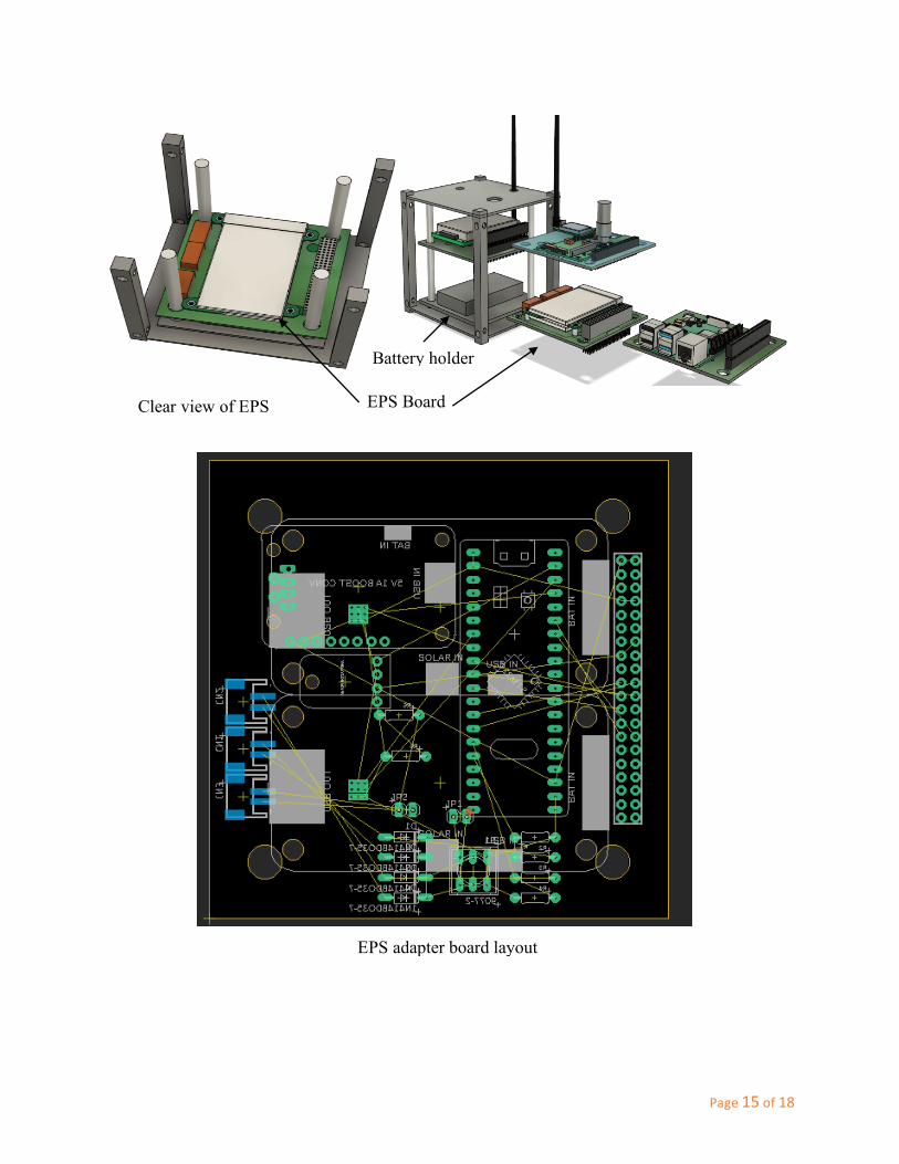
The batteries to be used in NaSPUoN are 18650 Lithium-Ion batteries. This selection was based on capacity and chemistry of batteries. More so, they already have flight heritage and cheap enough to be incorporated in this initial design. The batteries will be contained in a 3D-printed battery holder box.
Specifications • Capacity: 3400mAh • Charging current: 1A • Charging voltage: 4.2 V Lithium ion battery
Page15of18
EPS Board
Battery holder
Clear view of EPS
EPS adapter board layout

Page16of18
5. Structure
The NaSPUoN structure team is composed of members from the department of Mechanical Engineering. The team’s role is designing, simulating and manufacturing the structure of the cube-sat. The main function of the structure is to house the other subsystems within the mass and dimensional constraints of the cube-sat. It should also be able to withstand the vibrations during launch and deployment to protect the components within it.
In designing the structure of the cube-sat, we looked at the design process of space-grade structures and mimicked the same for our bench model. Various factors were considered during the design of the cube-sat structure. These are cost, material, thermal conductivity of the material and the manufacturing process. For space-grade satellites, various alloys of Aluminum are the best material for manufacture of the structure. Aluminum has a high strength to weight ratio and is very light making it ideal.
For the bench model, Polylactic Acid (PLA) material is used for the structure. PLA is a 3D-printable thermoplastic that has high strength, is light, and cheap and that renders it ideal for this project.
Design process for NaSPUoN structure
A design was settled on, based on constraints set by international standards for CubeSats. These constraints as previously mentioned are the size and weight of the structure. The structure designed should not only meet the constraints, but also be rigid enough to protect the internal components. The paper-design was then translated into Computer-Aided Design using Solidworks and Fusion 360 software.
1)Designonpaper
2)CADDrawings
3)Simulations
4)Testingforcriteria
5)3Dprinting

Page17of18
After drawing the design on CAD software, Finite Element studies were run to observe how our designs would fair against simulated loads. The loading conditions used in the simulations were based on loads recorded during launch of cube-sats.
Having ran the simulations and gotten the results, we compare the results of the simulation to those of scientific papers and those required by launchers. If the results do not match, we tweaked the design at specific points based on the results we get. This process is repeated until we get a final design.
The structure will be manufactured by 3D printing it. We will 3D print each individual panel separately and assemble them using screws.
The Process of 3D printing is:
• CAD Design and generating corresponding STL files.
• Slicing the design using slicing software.
• Generating G-Code on the 3D printer using the sliced designs.
We have currently embarked on the 3D printing process. However, the closure of schools and lockdown of Nairobi City has cast a huge drag on our progress.

Page18of18
CONCLUSION
Despite the challenges faced by the team, especially due to restrictions occasioned by Covid-19, the team has managed to work remotely for 5 months. During this time, the students have been introduced to CubeSat technology. They have also sharpened their design skills, utilizing software such as PCB and CAD design software. The multi-disciplinary composition of the team has also been a huge positive to the team. Each team can play to their strength, whilst benefiting from in domain knowledge of the other teams.
Procurement of components and items for the project also faced quite some challenges as the procurement process at UoN was not very clear from the onset. This led to a delay in making orders and subsequently some items ran out of stock, further delaying their purchase. The team is currently in the process of acquiring these items, whose shipping and arrival in Kenya is expected in the coming weeks.
The team, since March, was getting hands-on experience in the lab, in readiness for NaSPUoN integration. However, the closure of the university on 27th March has put this to a halt. Since much of the remaining work requires physical access to the lab, the closure will cause a significant delay in the delivery of the bench model. However, the team is committed to continue working remotely on tasks that can be performed from home. This is mostly on software development. Meanwhile, we hope that physical access to the lab will resume soon as well as the arrival of components.
Submitted on behalf of the Team by
Eng. Prof. Mwangi Mbuthia – Kenya Space Agency Research Chair
NaSPUoN - Principal Investigator
31stMarch,2021