
NASA's Solar Dynamics Observatory (SDO) – A Systems ... · 978-1-4577-0557-1/12/$26.00 ©2012...
12
978-1-4577-0557-1/12/$26.00 ©2012 IEEE 1 NASA’s Solar Dynamics Observatory (SDO): A Systems Approach to a Complex Mission John A. Ruffa Goddard Space Flight Center 8800 Greenbelt Rd Greenbelt, MD 20771 (301) 286-8247 [email protected] Michael Bay Bay Engineering Innovations 8800 Greenbelt Rd Greenbelt, MD 20771 (301) 286-9759 [email protected] David K. Ward Goddard Space Flight Center 8800 Greenbelt Rd Greenbelt, MD 20771 (301) 286-2170 [email protected] Peter J. Gonzales Bay Engineering Innovations 8800 Greenbelt Rd Greenbelt, MD 20771 (301) 286-6563 [email protected] Lisa M. Bartusek Goddard Space Flight Center 8800 Greenbelt Rd Greenbelt, MD 20771 (301) 286-1311 [email protected] William D. Pesnell Goddard Space Flight Center 8800 Greenbelt Rd Greenbelt, MD 20771 (301) 286-4009 [email protected] Abstract— The Solar Dynamics Observatory (SDO) includes three advanced instruments, massive science data volume, stringent science data completeness requirements, and a custom ground station to meet mission demands. The strict instrument science requirements imposed a number of challenging drivers on the overall mission system design, leading the SDO team to adopt an integrated systems engineering presence across all aspects of the mission to ensure that mission science requirements would be met. Key strategies were devised to address these system level drivers and mitigate identified threats to mission success. The global systems engineering team approach ensured that key drivers and risk areas were rigorously addressed through all phases of the mission, leading to the successful SDO launch and on-orbit operation. Since launch, SDO’s on-orbit performance has met all mission science requirements and enabled groundbreaking science observations, expanding our understanding of the Sun and its dynamic processes. TABLE OF CONTENTS 1. INTRODUCTION ................................................. 1 2. CHALLENGING SYSTEM DESIGN DRIVERS....... 3 3. INTEGRATED MISSION SYSTEM DESIGN .......... 4 4. SYSTEMS ENGINEERING ACROSS SUBSYSTEMS AND LIFECYCLE PHASES ................................. 6 5. KEY PROCESSES AND TOOLS ............................ 7 6. SDO PERFORMANCE AND SCIENCE ................. 9 7. SUMMARY ....................................................... 10 REFERENCES....................................................... 10 BIOGRAPHY ........................................................ 11 1. INTRODUCTION The Solar Dynamics Observatory (SDO), launched in February 2010, is the flagship mission of NASA’s “Living With a Star” (LWS) program. Described by scientists as “our Hubble on the Sun”, this challenging mission was designed to capture images of our closest star at an unprecedented resolution and cadence, unlocking secrets of solar activity and addressing questions previously unanswerable by other solar science missions. Arguably one of the largest, most advanced in-house missions designed, manufactured, and tested at NASA’s Goddard Space Flight Center (GSFC), SDO includes three advanced solar instruments containing six telescopes and eight detector arrays, massive science data volume, stringent science data completeness requirements, and a custom ground system to meet mission demands. As part of the LWS program, the SDO mission was assigned a number of mission objectives specifically designed to support the LWS goals of understanding the drivers of solar activity and variability that affect Earth and humanity. Specifically, SDO was designed to address seven science questions dealing with the sun’s dynamic activity and its effect on the earth: 1) What mechanisms drive the quasi-periodic 11-year cycle of solar activity? 2) How is active region magnetic flux synthesized, concentrated, and dispersed across the solar surface? 3) How does magnetic reconnection on small scales reorganize the large-scale field topology and current systems and how significant is it in heating the corona and accelerating the solar wind? 4) Where do the observed variations in the Sun‘s EUV spectral irradiance arise, and how do they relate to the magnetic activity cycles? https://ntrs.nasa.gov/search.jsp?R=20140009995 2018-09-16T01:08:37+00:00Z
Transcript of NASA's Solar Dynamics Observatory (SDO) – A Systems ... · 978-1-4577-0557-1/12/$26.00 ©2012...

978-1-4577-0557-1/12/$26.00 ©2012 IEEE 1
NASA’s Solar Dynamics Observatory (SDO): A Systems Approach to a Complex Mission
John A. Ruffa
Goddard Space Flight Center 8800 Greenbelt Rd
Greenbelt, MD 20771 (301) 286-8247
Michael Bay Bay Engineering Innovations
8800 Greenbelt Rd Greenbelt, MD 20771
(301) 286-9759 [email protected]
David K. Ward Goddard Space Flight Center
8800 Greenbelt Rd Greenbelt, MD 20771
(301) 286-2170 [email protected]
Peter J. Gonzales
Bay Engineering Innovations 8800 Greenbelt Rd
Greenbelt, MD 20771 (301) 286-6563
Lisa M. Bartusek Goddard Space Flight Center
8800 Greenbelt Rd Greenbelt, MD 20771
(301) 286-1311 [email protected]
William D. Pesnell
Goddard Space Flight Center 8800 Greenbelt Rd
Greenbelt, MD 20771 (301) 286-4009
Abstract— The Solar Dynamics Observatory (SDO) includes three advanced instruments, massive science data volume, stringent science data completeness requirements, and a custom ground station to meet mission demands. The strict instrument science requirements imposed a number of challenging drivers on the overall mission system design, leading the SDO team to adopt an integrated systems engineering presence across all aspects of the mission to ensure that mission science requirements would be met. Key strategies were devised to address these system level drivers and mitigate identified threats to mission success. The global systems engineering team approach ensured that key drivers and risk areas were rigorously addressed through all phases of the mission, leading to the successful SDO launch and on-orbit operation. Since launch, SDO’s on-orbit performance has met all mission science requirements and enabled groundbreaking science observations, expanding our understanding of the Sun and its dynamic processes.
TABLE OF CONTENTS 1. INTRODUCTION ................................................. 1�2. CHALLENGING SYSTEM DESIGN DRIVERS ....... 3�3. INTEGRATED MISSION SYSTEM DESIGN .......... 4�4. SYSTEMS ENGINEERING ACROSS SUBSYSTEMS AND LIFECYCLE PHASES ................................. 6�5. KEY PROCESSES AND TOOLS ............................ 7 6. SDO PERFORMANCE AND SCIENCE ................. 9 7. SUMMARY ....................................................... 10 REFERENCES ....................................................... 10�BIOGRAPHY ........................................................ 11�
1. INTRODUCTION
The Solar Dynamics Observatory (SDO), launched in February 2010, is the flagship mission of NASA’s “Living
With a Star” (LWS) program. Described by scientists as “our Hubble on the Sun”, this challenging mission was designed to capture images of our closest star at an unprecedented resolution and cadence, unlocking secrets of solar activity and addressing questions previously unanswerable by other solar science missions. Arguably one of the largest, most advanced in-house missions designed, manufactured, and tested at NASA’s Goddard Space Flight Center (GSFC), SDO includes three advanced solar instruments containing six telescopes and eight detector arrays, massive science data volume, stringent science data completeness requirements, and a custom ground system to meet mission demands.
As part of the LWS program, the SDO mission was assigned a number of mission objectives specifically designed to support the LWS goals of understanding the drivers of solar activity and variability that affect Earth and humanity. Specifically, SDO was designed to address seven science questions dealing with the sun’s dynamic activity and its effect on the earth: 1) What mechanisms drive the quasi-periodic 11-year cycle of solar activity? 2) How is active region magnetic flux synthesized, concentrated, and dispersed across the solar surface? 3) How does magnetic reconnection on small scales reorganize the large-scale field topology and current systems and how significant is it in heating the corona and accelerating the solar wind? 4) Where do the observed variations in the Sun‘s EUV spectral irradiance arise, and how do they relate to the magnetic activity cycles?
https://ntrs.nasa.gov/search.jsp?R=20140009995 2018-09-16T01:08:37+00:00Z

2
5) What magnetic field configurations lead to the coronal mass ejections (CMEs), filament eruptions, and flares that produce energetic particles and radiation? 6) Can the structure and dynamics of the solar wind near Earth be determined from the magnetic field configuration and atmospheric structure near the solar surface? 7) When will activity occur, and is it possible to make accurate and reliable forecasts of space weather and climate?
In order to address these seven science questions, the SDO mission carries three separate onboard science instruments, each tasked with a specific role in answering the seven science questions (Figure 1):
Figure 1 - View of SDO spacecraft and three science instruments
1) The Helioseismic and Magnetic Field Investigation (HMI). HMI employs two telescopes in a single housing to functionally look at the surface of the Sun and inwards, measuring the Doppler shifts due to oscillation velocities over the entire visible solar disk and performing high-resolution measurements of the longitudinal and vector magnetic field over the whole visible disk of the Sun. Analysis of these measurements furthers understanding of the interior processes governing the transition from solar minimum to solar maximum, as well as probing the dynamics of the near-surface shear layer to observe local strong flux regions before they reach the photosphere, and measuring the highly variable magnetic field. (Principal Investigator: Dr. Phil Scherrer, Stanford University)
2) The Atmospheric Imaging Assembly (AIA). AIA functionally looks at the surface of the Sun and outwards, capturing the initiation and progression of dynamic processes, with the spatial resolution necessary to understand their connection to the magnetic field and the spectral coverage to infer the processes at multiple temperatures. Using four multi-wavelength telescopes, AIA captures high-resolution, full-Sun images to provide chromospheric and coronal images at a 10-second cadence. (Principal Investigator: Alan Title, Lockheed-Martin Solar and Astrophysical Laboratory) 3) The EUV Variability Experiment (EVE). EVE measures the sun’s extreme ultraviolet spectral irradiance from 0.1 to 105 nm at a cadence of ten seconds, allowing measurement of the energy input into the complex processes of the Earth's atmosphere and near-Earth space. (Principal Investigator: Dr. Tom Woods, University of Colorado)
The unique nature of the SDO instrument science observations and their associated requirements imposed a number of challenging drivers on the overall SDO mission system design, forcing SDO system complexity significantly beyond that of other more conventional missions. The early identification of these key drivers was an important factor in the success of the SDO development effort, guiding the team in formulating an integrated SDO implementation concept to meet stringent science requirements and defining key risk areas that threatened mission success. Because these mission drivers impacted virtually all subsystems in the SDO mission implementation (instruments, spacecraft bus and ground system), the SDO systems team developed and employed an integrated systems engineering approach, ensuring system-level integration of all subsystems, all development teams, and along all phases of the mission development effort, all aggressively working together to mitigate threats to mission success and identify potential unintended interactions. Key strategies were devised to address these system level drivers, along with the establishment of specific systems-level tests and tracking budgets. Working closely with mission subsystems and discipline areas, the SDO team established a common systems-level mindset among the team to ensure that these key drivers and risk areas were constantly addressed through all phases of the mission. Well over a year into its mission, SDO’s on-orbit performance has met all mission science requirements and enabled closer observation and study of our neighboring star (Figure 2). The spectacular images of our sun have captured the interest of the public, gracing the covers of numerous newspapers and magazines, and science observations are dramatically expanding our understanding of the sun and its dynamic processes.
3
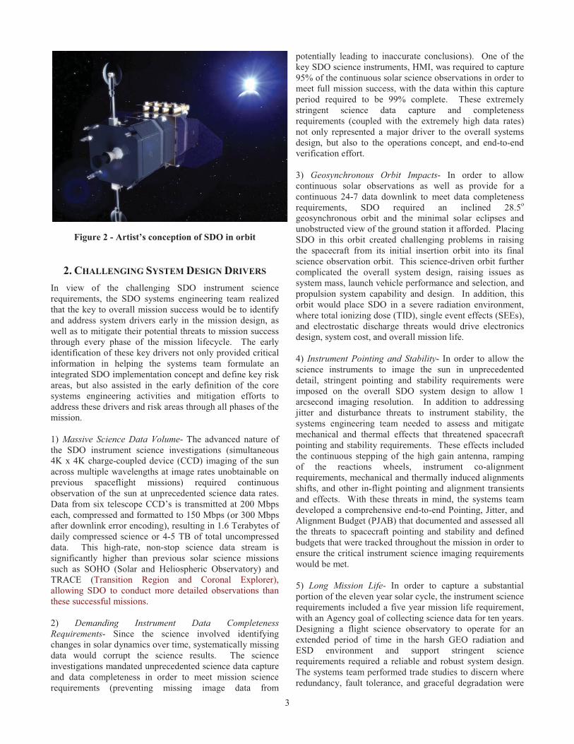
Figure 2 - Artist’s conception of SDO in orbit
2. CHALLENGING SYSTEM DESIGN DRIVERS In view of the challenging SDO instrument science requirements, the SDO systems engineering team realized that the key to overall mission success would be to identify and address system drivers early in the mission design, as well as to mitigate their potential threats to mission success through every phase of the mission lifecycle. The early identification of these key drivers not only provided critical information in helping the systems team formulate an integrated SDO implementation concept and define key risk areas, but also assisted in the early definition of the core systems engineering activities and mitigation efforts to address these drivers and risk areas through all phases of the mission. 1) Massive Science Data Volume- The advanced nature of the SDO instrument science investigations (simultaneous 4K x 4K charge-coupled device (CCD) imaging of the sun across multiple wavelengths at image rates unobtainable on previous spaceflight missions) required continuous observation of the sun at unprecedented science data rates. Data from six telescope CCD’s is transmitted at 200 Mbps each, compressed and formatted to 150 Mbps (or 300 Mbps after downlink error encoding), resulting in 1.6 Terabytes of daily compressed science or 4-5 TB of total uncompressed data. This high-rate, non-stop science data stream is significantly higher than previous solar science missions such as SOHO (Solar and Heliospheric Observatory) and TRACE (Transition Region and Coronal Explorer), allowing SDO to conduct more detailed observations than these successful missions. 2) Demanding Instrument Data Completeness Requirements- Since the science involved identifying changes in solar dynamics over time, systematically missing data would corrupt the science results. The science investigations mandated unprecedented science data capture and data completeness in order to meet mission science requirements (preventing missing image data from
potentially leading to inaccurate conclusions). One of the key SDO science instruments, HMI, was required to capture 95% of the continuous solar science observations in order to meet full mission success, with the data within this capture period required to be 99% complete. These extremely stringent science data capture and completeness requirements (coupled with the extremely high data rates) not only represented a major driver to the overall systems design, but also to the operations concept, and end-to-end verification effort. 3) Geosynchronous Orbit Impacts- In order to allow continuous solar observations as well as provide for a continuous 24-7 data downlink to meet data completeness requirements, SDO required an inclined 28.5o geosynchronous orbit and the minimal solar eclipses and unobstructed view of the ground station it afforded. Placing SDO in this orbit created challenging problems in raising the spacecraft from its initial insertion orbit into its final science observation orbit. This science-driven orbit further complicated the overall system design, raising issues as system mass, launch vehicle performance and selection, and propulsion system capability and design. In addition, this orbit would place SDO in a severe radiation environment, where total ionizing dose (TID), single event effects (SEEs), and electrostatic discharge threats would drive electronics design, system cost, and overall mission life. 4) Instrument Pointing and Stability- In order to allow the science instruments to image the sun in unprecedented detail, stringent pointing and stability requirements were imposed on the overall SDO system design to allow 1 arcsecond imaging resolution. In addition to addressing jitter and disturbance threats to instrument stability, the systems engineering team needed to assess and mitigate mechanical and thermal effects that threatened spacecraft pointing and stability requirements. These effects included the continuous stepping of the high gain antenna, ramping of the reactions wheels, instrument co-alignment requirements, mechanical and thermally induced alignments shifts, and other in-flight pointing and alignment transients and effects. With these threats in mind, the systems team developed a comprehensive end-to-end Pointing, Jitter, and Alignment Budget (PJAB) that documented and assessed all the threats to spacecraft pointing and stability and defined budgets that were tracked throughout the mission in order to ensure the critical instrument science imaging requirements would be met. 5) Long Mission Life- In order to capture a substantial portion of the eleven year solar cycle, the instrument science requirements included a five year mission life requirement, with an Agency goal of collecting science data for ten years. Designing a flight science observatory to operate for an extended period of time in the harsh GEO radiation and ESD environment and support stringent science requirements required a reliable and robust system design. The systems team performed trade studies to discern where redundancy, fault tolerance, and graceful degradation were

4
necessary to ensure that environmental and mission life requirements would be met. A comprehensive life-testing program of mechanisms and moving parts was implemented to ensure that system degradation and failure of key components would not threaten science collection and performance.
3. INTEGRATED MISSION SYSTEM DESIGN With these five critical drivers identified, the systems engineering team developed an integrated mission concept solution to specifically address these mission drivers and effectively meet SDO instrument science requirements. In addition, they also implemented key systems engineering lifecycle strategies and processes to further track and mitigate threats that these drivers would incur throughout all phases of the mission development effort.
Rather than viewing the mission as a disparate set of subsystems, all areas of the mission (instruments, spacecraft bus, and ground station) were integrated as a tightly coupled system, with the SDO systems team working as an integrated umbrella over all aspects of the development effort. This integrated approach allowed the systems team greater freedom and flexibility to explore and pursue alternative and innovative development approaches, resource allocations, system-level trade studies across the overall design, and employ best common sense approaches to challenging implementation issues.
The following are some of the key missions design choices devised to address the system level drivers, as well as specific systems-level tests and budgets to track and mitigate threats to mission success.
High Speed Science Data Stream- To address the challenge of huge data volume and tight data capture/completeness requirements, the systems team implemented a separate high rate Ka-band downlink to continuously transmit science data to a dedicated ground station. An onboard spacecraft high speed data bus links the three SDO science instruments and integrates their high rate data streams into a single science data downlink that is transmitted to the ground station. New technology was developed by the SDO team in the form of a solid state Ka Band RF modulator and transmitter to send the data to the ground.
Data Storage Solution- Full disk solar images utilized 4k by 4k (16 megapixel) CCDs that were assembled into six cameras, with each camera creating a 200 Mbps stream compressed and multiplexed into a continuous 150 Mbps downlink stream. Because of this large, continuous data stream from the SDO instruments, the size and complexity of a flight science data recorder would have been a prohibitively difficult implementation challenge, especially alongside the stringent science data completeness requirements and the complexity this would add to recorder management and playback. Instead, as the result of an early
systems trade study, the systems team opted for a continuous “bent pipe” science data stream from the instruments down to a ground-based data storage center, where the data was initially archived for subsequent transmission to the instrument science operations centers (SOCs). This innovative approach essentially relocated the science data recorder from the spacecraft to the ground station (where it could be more effectively and economically managed). This decision shifted the challenge from designing and operating a huge onboard flight recorder to focusing on reliably transmitting the science data to the ground station. The GEO orbit enabled this systems level solution and was one of the driving factors for the orbit selection. Ground Station Design Implementation- As part of ensuring that the instrument science data is reliably transmitted to and safely stored in the SDO ground station data archive, a trade study was conducted to determine the optimum ground station site to minimize weather and other environmental impacts to the error-free transmission and archiving of the SDO data stream. As a result of this trade, a dedicated SDO ground station was built in White Sands, NM, incorporating two separate 18 m antennas located three miles apart from each other, providing geographical diversity to protect against local weather events. This dedicated ground station also housed the SDO 30-day science data storage archive, which incorporated an innovative system design to store and continuously transmit instrument science data to the respective instrument SOCs in Palo Alto, California and Boulder, Colorado. The ground station is also designed to support autonomous retransmission of data to the SOCs for up to 30 days after initial transmission in the event any data is lost or degraded during transmission or storage at the SOCs. This retransmission capability further protects the instrument science data and acts as yet another layered safeguard to meeting the stringent SDO data capture requirements. Data Capture Budget Verification- In order to further ensure that the instrument science data completeness requirements were met (including the most stringent HMI science requirements of 95% capture/99% completeness), the systems team surveyed and documented all the “threats” to science data collection. Since minimizing data loss was such an important driver to meeting the SDO science requirements, a Data Capture Budget was used to identify and document data loss budgets for each threat area. Items included in this data capture budget included on-orbit effects (radiations induced events, safehold, and other unplanned anomalies), planned mission operations disruptions (yearly orbital eclipses, periodic momentum unloading operations, instrument calibration activities), ground station interruptions (weather, periodic antenna maintenance, anomalies), and other potential areas that could impact the reliable flow of data to the ground station before it is captured and reliably archived. This Data Capture Budget became the SDO “bible” for evaluating all design or configuration changes to ensure that they did not

5
negatively affect SDO science data completeness performance and margins. Autonomous Onboard High Speed Science Data Bus Recovery- An additional layer safeguarding the SDO science data capture completeness requirements, the systems team implemented an autonomous monitoring and recovery capability into the flight high speed science data bus design. This approach removed the potential time lag (and data loss) between ground detection of an on-orbit science data bus anomaly and ground-commanded science bus recovery. Even a short science data flow interruption (if not immediately caught by the ground system team) could result in mission science requirements being seriously impacted or lost. This onboard autonomous approach took the ground system out of the loop in all but the most serious recovery options and added a further safeguard to preserving the science data continuity. This autonomous recovery was exhaustively tested across SDO to ensure the effectiveness of this autonomous recovery function prior to launch. End-to-End Science Data Flow Test- Due to the complexity of the end-to-end science data flow, a single end-to-end test from instrument CCDs through the science data pipeline to the instrument SOCs in a “test as you fly” manner was not feasible. Because of the criticality of this data path, the systems team developed a creative approach to partition this test into overlapping pieces that would together effectively verify the overall system performance by serving as an adequate proxy to a “test as you fly” end-to-end test. This science data test verified in a distributed fashion the entire science dataflow using breadboards and simulators, progressing later to engineering units and actual flight hardware, and finally including field tests at the newly built White Sands SDO ground station site using representative SDO hardware mounted miles away on collimation towers as RF science data sources. Each test had sufficient overlap with other parts of the larger end-to-test to ensure that there were no “gaps” that would mask interface or data flow issues. Realizing the criticality of this end-to-end test, the systems team presented the test plan and philosophy to a NASA appointed independent review team to ensure that this critical data interface verification was carefully reviewed, reporting back to them later to demonstrate the verification of this key interface. Pointing, Jitter, and Alignment Verification- In order to meet the stringent science imaging requirements (and corresponding pointing and jitter requirements), the systems team developed a comprehensive Pointing, Jitter, and Alignment Budget (PJAB) which was used to identify and document pointing/jitter budgets for each threat area. Each “threat’ to pointing and jitter was clearly identified, defined, and a portion of the overall system budget was assigned to each. To further assess and quantify these threats, detailed analysis was done to understand specific jitter sources and their effect on the integrated system. Wherever possible, specific hardware jitter tests (using Kistler table testing and other methods) were employed to gather actual jitter inputs
to quantify threats. When the PJAB data revealed exceedances in areas of the jitter budget, the systems team creatively employed operational workarounds (such as limiting reaction wheel speeds to narrower ranges and modifying RF high gain antenna stepping) as supplemental operational solutions to ensure sufficient margin against the science image pointing requirements. On-orbit jitter testing was later conducted to measure actual performance on station, which allowed some of the previously-implemented operational restrictions (such as reaction wheel speed limitations) to be relaxed once in orbit (increasing system performance and flexibility). The implementation and use of the PJAB by the systems team also resulted in reducing SDO system technical complexity as well as significant cost and schedule savings in the SDO development effort, allowing the systems team to forgo the use of costly and more invasive jitter control approaches (such as dampers for reactions wheels) in the SDO design and development effort. In addition, the SDO team developed a backup plan to allow the SDO instrument telescope CCD’s the option of scheduling image collection in between high gain antenna steps if needed, mitigating potential jitter causes by the high gain antenna motion. Detailed Parts Selection and Systems Application Review- In light of the mission life requirements, as well as the hazardous radiation environment of the Geo orbit (and the impact of radiation effects on the science data capture/completeness budget), the systems team instituted a stringent electrical parts program to mitigate these threats. The overall project strategy involved a consolidated parts purchase for the SDO spacecraft subsystems and some common instrument interfaces, reducing spacecraft costs involved in qualifying radiation hardened parts. Chaired by the SDO systems team, the parts control board (PCB) individually examined and assessed each electrical part used on the SDO observatory, whether part of the consolidated buy or not, including all procured components and instruments. The PCB worked with designers to verify each part met electrical, radiation, derating, and application specific requirements, with the systems chair providing the system-level impact assessment when application or performance issues were being assessed. Any parts-related susceptibilities were examined in light of overall mission requirements and either were mitigated in the electrical design or operations concept to ensure mission requirements would be preserved. This parts review was iterated many times over the entire development effort, from initial parts selection to final end-item parts review to ensure that the intended parts were actually implemented in the final flight article. This parts review program and system engineering scrutiny of parts selection and use was critical in mitigating any possible threats to instrument science performance and overall mission success. Bi-propellant Propulsion System Design- In order to meet the requirement to raise SDO to its final Geosynchronous orbit, the SDO developed a bi-propellant propulsion system (since the initial mono-prop system envisioned as part of the
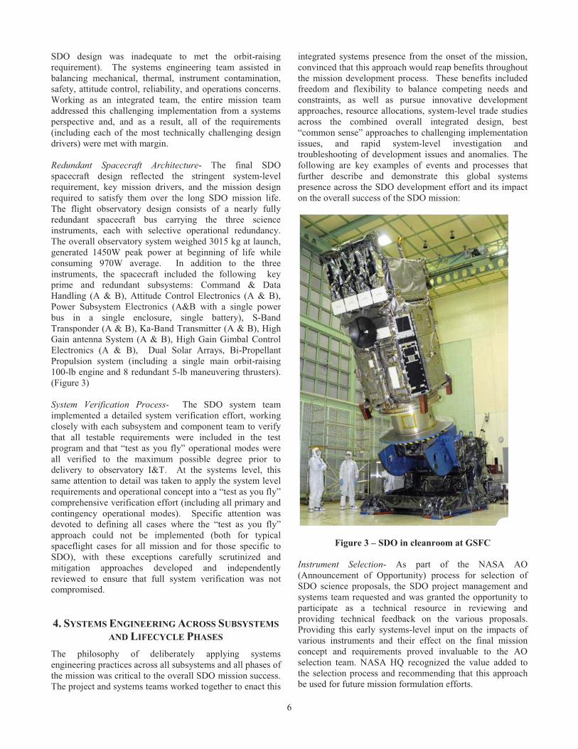
6
SDO design was inadequate to met the orbit-raising requirement). The systems engineering team assisted in balancing mechanical, thermal, instrument contamination, safety, attitude control, reliability, and operations concerns. Working as an integrated team, the entire mission team addressed this challenging implementation from a systems perspective and, and as a result, all of the requirements (including each of the most technically challenging design drivers) were met with margin. Redundant Spacecraft Architecture- The final SDO spacecraft design reflected the stringent system-level requirement, key mission drivers, and the mission design required to satisfy them over the long SDO mission life. The flight observatory design consists of a nearly fully redundant spacecraft bus carrying the three science instruments, each with selective operational redundancy. The overall observatory system weighed 3015 kg at launch, generated 1450W peak power at beginning of life while consuming 970W average. In addition to the three instruments, the spacecraft included the following key prime and redundant subsystems: Command & Data Handling (A & B), Attitude Control Electronics (A & B), Power Subsystem Electronics (A&B with a single power bus in a single enclosure, single battery), S-Band Transponder (A & B), Ka-Band Transmitter (A & B), High Gain antenna System (A & B), High Gain Gimbal Control Electronics (A & B), Dual Solar Arrays, Bi-Propellant Propulsion system (including a single main orbit-raising 100-lb engine and 8 redundant 5-lb maneuvering thrusters). (Figure 3) System Verification Process- The SDO system team implemented a detailed system verification effort, working closely with each subsystem and component team to verify that all testable requirements were included in the test program and that “test as you fly” operational modes were all verified to the maximum possible degree prior to delivery to observatory I&T. At the systems level, this same attention to detail was taken to apply the system level requirements and operational concept into a “test as you fly” comprehensive verification effort (including all primary and contingency operational modes). Specific attention was devoted to defining all cases where the “test as you fly” approach could not be implemented (both for typical spaceflight cases for all mission and for those specific to SDO), with these exceptions carefully scrutinized and mitigation approaches developed and independently reviewed to ensure that full system verification was not compromised. 4. SYSTEMS ENGINEERING ACROSS SUBSYSTEMS
AND LIFECYCLE PHASES The philosophy of deliberately applying systems engineering practices across all subsystems and all phases of the mission was critical to the overall SDO mission success. The project and systems teams worked together to enact this
integrated systems presence from the onset of the mission, convinced that this approach would reap benefits throughout the mission development process. These benefits included freedom and flexibility to balance competing needs and constraints, as well as pursue innovative development approaches, resource allocations, system-level trade studies across the combined overall integrated design, best “common sense” approaches to challenging implementation issues, and rapid system-level investigation and troubleshooting of development issues and anomalies. The following are key examples of events and processes that further describe and demonstrate this global systems presence across the SDO development effort and its impact on the overall success of the SDO mission:
Figure 3 – SDO in cleanroom at GSFC
Instrument Selection- As part of the NASA AO (Announcement of Opportunity) process for selection of SDO science proposals, the SDO project management and systems team requested and was granted the opportunity to participate as a technical resource in reviewing and providing technical feedback on the various proposals. Providing this early systems-level input on the impacts of various instruments and their effect on the final mission concept and requirements proved invaluable to the AO selection team. NASA HQ recognized the value added to the selection process and recommending that this approach be used for future mission formulation efforts.

7
Concept Development- As soon as the instrument teams were selected, the Systems team began to work with all instruments, subsystems, and components vendors to develop a unified, cohesive systems-level concept where the various pieces fit into a single integrated mission design. After determining that the design could accomplish the mission as outlined in the operations concept, design decisions were captured as the requirements. A top-down Systems Engineering plan captured plan technical aspects of developing the mission with the identification of potential issues and risks as a major focus. Instrument and subsystem teams were identified as de facto members of the system team and brought in to help develop and define the system implementation and ops concept. Systems Inputs to Project Plan- The SDO systems team was an integral member of the project planning effort, providing technical expertise to the project management team in developing the project plan that would help define and guide the programmatic aspects of the development effort (including the “grass roots” cost estimate, the work breakdown structure, as well as the master SDO development, integration, and test schedule). Participation in Project Monthly Reviews- The systems team was an active participant in the monthly programmatic meetings held between SDO Project Management, Safety and Missions Assurance (SMA), and the various instrument and subsystems, providing valuable inputs on technical progress and helping to assess and mitigate issues as they arose. These meetings provided a forum to discuss and debate issues and risks with a balance programmatic, technical and mission assurance outcome best suited for the overall mission. Review of Subsystem Designs- The SDO systems engineering team worked in an integral fashion with the subsystem design teams, participating in peer reviews of all subsystem designs, as well as leading the required pre-manufacturing review of all engineering and flight units. This technical participation and focus on potential design and integration issues helped identify and correct design and interface issues early in the development effort and was a significant risk mitigator in minimizing interface and manufacturing issues. Testing and Delivery Reviews- Prior to flight component environmental testing, the systems team reviewed subsystem requirements, traced them to the subsystem functional and environmental test program, and verified that the test effort adequately encompassed the subsystem requirements and objectives. Prior to subsystem delivery and spacecraft integration, the systems team held delivery acceptance reviews, carefully examining the results of the subsystem acceptance test programs, requirements verification matrices, and all relevant documentation to verify that subsystem components had completed the acceptance test program and were ready for delivery for integration to the SDO spacecraft.
Observatory Integration and Test- The Systems team provided additional leadership and a constant presence during the SDO integration and test (I&T) effort, serving as the floor leads through all shifts of the I&T effort and leading as test directors during observatory integration, testing and troubleshooting efforts. In addition, the SDO system team developed and served as test leads for the Observatory comprehensive performance tests (CPT) and environmental test program.
5. KEY PROCESSES AND TOOLS In order to support this tightly coupled systems engineering effort across all elements and phases of the SDO development effort, the SDO systems team pursued both the development of new tools as well as the enhancement of existing processes and tools in order to enable a global systems presence in the integrated systems design, as well as to ensure that threats against meeting SDO mission requirements were identified and mitigated at every phase of the project. Systems Engineering Management Plan (SEMP)- The SDO SEMP was developed early as a blueprint for systems engineering activities throughout the SDO development effort. Detailing specific SDO activities, roles, responsibilities, reviews and other critical activities for each phase of the program, this document evolved with the project along with its lifecycle and captured the system engineering effort through each phase of the mission. At each major programmatic review “gate” the SEMP plan (and its guidelines of what needed to be accomplished in each mission phase) was presented as a key metric of completeness of systems activities for the past development phase as well as a guide for future activities in the next engineering phase. Risk Management Process- SDO’s robust risk management process was a prime example of the project team’s focus on proactively identifying and documenting risk areas, allowing the team to identify specific mitigation approaches to target these risk areas and vigorously track them until addressed. Each active risk was assigned to a member of the system team to track and disposition on a monthly basis until mitigated. SDO’s use of the risk management system as an effective tool to aggressively identify and track threats to mission success was noted by the NASA HQ chair as part of SDO’s pre-launch Safety and Mission Success Review (SMSR), who commented as part of his assessment of the SDO effort, “For this mission, it is notable that there are fewer spacecraft and launch vehicle residual risks than normal”. This is a clear example of the fruit of an aggressive and effective risk management effort, especially considering the size, scope, and complexity of the SDO mission. SDO Management Information System- An important “spin-off” of the SDO project was the SDO Management

8
Information System (MIS). This web-based, interactive tool was conceptualized and designed as a joint venture between the SDO project management and systems team as a critical tool to integrate configuration management, requirements, verification, work authorization, failure reporting, and library functions in a new and unprecedented fashion at GSFC. Given the systems complexity of the SDO development effort and the clear need for integrated systems engineering oversight for all aspects and phases of the SDO development effort, the development of the SDO MIS was seen as a critical need in realizing this integrated systems approach. The systems team was a critical partner during every step of the MIS development, defining how the end-item would serve as a tool for critical configuration management (CM) and systems engineering functions, focusing on MIS requirements development and “story boarding” the final MIS system test and implementation. The systems team was particularly instrumental in defining and guiding the approach in which designs, requirements, as-built documentation and test results were linked in the final system, as well as pushing a key requirement that the MIS system be available “24-7” from any location, a key decision which turned out to be a huge productivity multiplier for the SDO project. To date, 16 other GSFC projects have adopted the MIS, providing a clear testament to the value of this tool for Project/Systems Management. SDO Configuration Change Board (CCB)- SDO adopted a very strong configuration management “culture” from the very beginning of the project as a direct result of the lessons learned by members of the systems team on past programs. Working closely with the project management team, the SDO systems team constantly promoted the effective use of a strong CM system (and the development of valuable CM tools, such as the SDO MIS described above), believing that a strong CM effort saves time, money and ensures the team actually builds what they intended. The systems team emphasized the need to clearly define, review, and document change control for all configuration changes (which was essential on a mission with the size, scope, and complexity of SDO and its distributed development team), mandating the use of the MIS as a central point for this purpose as they evaluated and documented eleven hundred change requests. Reliability Analysis of SDO Designs- Early exploration of potential mission risks through the use of reliability and fault assessment tools including top down fault tree analysis, and functional failure modes and effects analysis (FMEA) allowed proactive evaluation of alternatives to eliminate or mitigate risks. After designs matured, bottoms up FMEA and reliability predictions were integrated in a mission level Fault Logic Diagram [1], which linked the top down and bottoms up work to ensure considerations critical for mission success were not overlooked. The SDO systems team carefully reviewed and assessed not only the overall system design, but delved into the details of many of the key subsystem component designs in order to chase down “weak links” to overall system reliability. As these were identified,
architectural and design changes were proposed and reviewed against the SDO mission science requirements in order to ensure SDO mission success. As a result of this effort, specific changes were made to a number of subsystems and instrument architecture and components designs, further enhancing SDO reliability. Parts Control Board (PCB)- As previously mentioned, the SDO systems team provided the chair for the SDO PCB chartered with examining each part not only from the traditional parts application point of view, but also reviewing the systems design and applicability of every part in the SDO systems design. This unprecedented involvement of the SDO systems team in parts performance and applicability review driven by the severe geosynchronous orbital environment and the common part procurement approach is another example of systems team involvement and an integrated approach which sought to prevent parts and their application (or misapplication) from becoming a weak link for the system. Failure Review Board (FRB) Process- Working hand-in-hand with the mission assurance team, the SDO systems team promoted the aggressive use of GSFC problem reporting tools and was a key player in the identification, documentation, investigation, and resolution of all problems reports in the SDO development and test effort. For each anomaly, a systems team member participated in the standing FRB process, typically assigning a member to help investigate and resolve particularly difficult anomalies and issues as they arose. Of particular note was the objective to avoid problems with a “could not duplicate” or “one time only” aspect that might form a residual risk. Extra effort was expended to resolve such anomalies or minimize the potential mission impacts should they recur in flight. [2] This pivotal role of the systems team in anomaly investigation and resolution was a key factor in assessing the system level impact of anomalies as they arose and resolving them in a timely and effective manner. EMI Control Board- The early establishment of a system-level EMI board was instrumental in carefully surveying for potential EMI issues across the whole mission, looking for threats to the delivery of instrument science. Examination and implementation of grounding approaches started early along with early testing resulted in a smooth iteration with no EMI problems and non missing / unaccounted data on these high speed data lines. “Test as you Fly”- Faithful adherence to the sound systems principle of “test as you fly and fly as you test” becomes increasingly more important as systems become more complex and more difficult to test. This principle was applied in three major focus areas on SDO.
- Verification of the end-to-end science data and the high speed science data bus. Because the system could not be tested in a typical end-to-end fashion, the testing was tested ‘piecewise” with specific attention to overlapping the

9
various test segments. This ensured that the entire end-to-end system was adequately tested without allowing any crucial aspect to be missed or lost in between test segments.
- Verification of flight software. A high fidelity
test bed (known as a “flat satellite” or “Flatsat”) built of flight-like engineering test unit (ETU) spacecraft components and ground support equipment was used as a high fidelity platform for flight software testing as well as high fidelity simulations of spacecraft dynamics. Since attitude control dynamics could not be simulated with the real world spacecraft system, the software was tested against a simulator and the simulator validated against the actual SDO spacecraft.
- Comprehensive Performance Test (CPT). The
organization and structure of the SDO was organized to mimic the actual planned flight operations concept through all phases and activities of mission operations. All spacecraft components and all three flight instruments underwent parallel testing in flight-like modes and interactions to encourage the discovery of unintended interactions between subsystem elements.
6. SDO PERFORMANCE AND SCIENCE Since its launch in February 2010 and the completion of its subsequent on-orbit commissioning activities, SDO flight performance has been exemplary, meeting or exceeding mission requirements. A key driver in the SDO mission design was the need to accommodate the massive science data volume yet still meet demanding science data completeness requirements. Since the beginning of on-orbit science operations, the SDO data system, including the on-board high speed data bus, Ka-Band RF downlink, two dedicated ground antennas and the SDO data distribution system continues to successfully deliver approximately 1.6 Terabytes of compressed science data each day. The robustness of the dual ground antennas and data distribution system fault tolerant architecture has prevented numerous data losses that would have occurred in a single-string ground system. After the first year of science operations, data loss from the SDO ground station was well within its per year allocation and data losses only occurred at times when either of the two ground antennas was down for maintenance. It is clear that the decision to forgo a huge spacecraft on-board data recorder and build a redundant, robust ground station was the right decision to maximize data capture. Since the start of science operations, the SDO flight operations team compared the actual data loss from each of the budgeted items to the Data Capture Budget loss allocations. For HMI, the instrument with the most stringent capture requirement, the actual data loss was less than 50% of the allocation, well within mission data loss allocation requirements. The performance of the SDO spacecraft has been
exemplary. There have been no significant hardware failures and only minor hardware perfomrance trends being monitored by the operations team, none with any noticeable effect on the performance of the observatory. Though the spacecraft has features designed to survive radiation induced upsets and even, in the case of the high speed data bus, autonomously restore data delivery functions interrupted by faults, these features have not yet been exercised by the on-orbit environment despite three major solar storms since SDO launch. This speaks volumes to the comprehensive parts selection and application review conducted during the spacecraft electronics design effort. Instrument pointing and jitter performance results are best seen by simply looking at the sharpness of SDOs images of the sun. During commissioning the team verified the spacecraft met the required arc-second pointing and control required by the instruments. One of the results of a comprehensive post-launch jitter test demonstrated system performance margins that allowed the reaction wheels to be operated at much higher speeds than planned, thus significantly reducing the frequency of momentum unload maneuvers and reducing the frequency of science interruptions caused by these maneuvers. Overall, SDO performance and consistent on-orbit operations meets or exceeds all the requirements imposed by the systems team’s mission drivers set forth at the outset of the design of the mission. Of course, the true measure of the SDO mission is the science return and how the mission expands the understanding of the Sun and meets the mission science objectives. Since its launch, SDO has returned over 50 million images of our closest star at an unprecedented resolution and cadence, unlocking secrets of solar activity and the space weather it causes at Earth. Since the first day of collecting data, SDO has provided unprecedented views and measurements of erupting plasma filaments as they expand, twist, and explode off the surface of the Sun (Figure 4). The images of solar activity produced by SDO provide high spatial resolution and rapid image cadence, coupled with spectral measurements needed to measure the energy emitted by that activity. Together, these measurements allow the details of solar activity to be observed in an unprecedented manner. New science discoveries have already been made using data from SDO; these include
- Discovering a late-phase of solar flares by accurately measuring the total amount of energy given off by during the flares using data from EVE instrument measurements. [3]
- Predicting the emergence of sunspots deep inside
the solar interior, days before indications begin to appear on the outer solar disk. [4] This discovery by the HMI telescope, a major goal of the SDO mission, may eventually provide early warnings about solar activity and extend predictions of space weather forecasts.

10
- Detection and real-time observation by the AIA telescopes of a sun-grazing comet as it passed in front of the Sun and evaporated. [5] This unique observation allowed scientists to deduce the mass of the comet, a rare event even after many years of monitoring comets as they navigate around the solar system.
- Observations from the AIA instrument have
provided new understanding as to why the temperature of the sun’s outer atmosphere (or corona) is millions of degrees hotter than its surface (or photosphere). [6]
Figure 4- Portion of “First Light” image from AIA capturing coronal mass ejection
In addition, by emphasizing near-real-time public access to its data, SDO’s impact has been felt well beyond the solar science and engineering community. The public response and excitement about the images from SDO has overwhelmed everyone’s expectations. The spectacular images of our sun have captured the interest of the public, gracing the covers of numerous newspapers and magazines worldwide, and sciences observations are dramatically expanding our understanding of the sun and its dynamic processes.
7. SUMMARY
The SDO mission serves as a clear example of the importance of the systems engineering role across all phases of the mission development lifecycle and its contribution to mission success. The best metric to evaluate the success of this approach is in the successful launch and the on-orbit
performance of the SDO mission itself, which, despite challenging technical drivers and development obstacles along way, is currently enabling ground-breaking science after only two years into its five-year mission life. The SDO team was able to navigate the complex challenges of the SDO development effort and deliver a flagship science observatory that fulfills NASA’s commitment to science and space weather communities. In recognition of the importance of the systems engineering effort and its contribution towards the successful development, launch, and on-orbit operations of the SDO mission, the SDO Systems Engineering team was awarded the 2010 NASA Systems Engineering Excellence Award. While the complexity and stringent requirements of the SDO mission clearly benefitted this approach, missions of all size and complexity can clearly benefit from the implementation of this integrated end-to-end systems engineering approach. In fact, many other NASA missions implement similar systems engineering methodologies throughout their mission development lifecycles and enjoy similar benefits and success. It is important to note that the success of this systems engineering approach would never have been possible without the clear buy-in and active cooperation of the SDO Project Management team, which worked closely with and enabled the Systems Engineering team throughout all phases of the mission. This cooperative partnership was a key facet in the SDO success, not only in enabling the systems engineering team to provide the umbrella coverage throughout all phases and aspects of the mission, but also in developing a close, cooperative teaming relationship focused towards mission success within programmatic requirements and constraints. In addition, it is important to acknowledge the essential role of the three SDO science teams in the development and on-orbit operation of the advanced instruments that form the basis of the observatory and mission. Without their vision, experience, and partnership with NASA, this mission and advanced observatory described here would never have been designed or built.
REFERENCES [1] The Power of an Integrated Logic Diagram for Risk Management, Bay, Michael, NASA Risk Management Symposium, September 2003 [2] SDO Lessons Affirmed, B. Robertson, M. Bay, ASK Magazine, Vol , p41 [3] Woods, T. N., Hock, R., Eparvier, F., Jones, A. R., Chamberlin, P. C., Klimchuk, J. A., Didkovsky, L., Judge, D., Mariska, J., Warren, H., Schrijver, C. J., Webb, D. F., Bailey, S., and Tobiska, W. K., 2011, New solar extreme-ultraviolet irradiance observations during flares, Ap. J., 739, 59.

11
[4] Stathis Ilonidis, Junwei Zhao, and Alexander Kosovichev, "Detection of Emerging Sunspot Regions in the Solar Interior", Science, August 19, 2011 (vol. 333 no. 6045, pp. 993-996) [5] Schrijver, C. J., J. C. Brown, K. Battams, P. Saint-Hilaire, W. Liu, H. Hudson, W. D. Pesnell, Sun-grazing comet C/2011 1 N3 (SOHO) sublimating within the solar corona, 2011, Science, in press. [6] B. De Pontieu, S. W. McIntosh, M. Carlsson, V. H. Hansteen, T. D. Tarbell, P. Boerner, J. Martinez-Sykora, C. J. Schrijver, and A. M. Title, “The Origins of Hot Plasma in the Solar Corona”, Science, January 7, 2011 (Vol. 331 no. 6013 pp. 55-58)
BIOGRAPHIES
John� Ruffa is a Systems Engineer in the Systems Engineering Branch at the Goddard Space Flight Center (GSFC) in Greenbelt, MD. He served previously as part of the in-house GSFC development teams for the Rossi X-Ray Timing Explorer (RXTE) and the Wilkinson Microwave
Anisotropy Probe (WMAP) missions. He was the Mission Systems Engineer for the Solar Dynamics Observatory, which successfully launched from Cape Canaveral in February 2010. John has a BSEE from the University of Maryland and an MSEE from the Johns Hopkins University.
David� Ward is a Systems Engineer at NASA's Goddard Space Flight Center and was the Spacecraft Systems Engineer on SDO. Previous to SDO, he worked on various other GSFC missions including the Wilkinson Microwave Anisotropy Probe (WMAP), the Tropical Rainfall Measuring
Mission (TRMM), and the Extreme Ultraviolet Explorer (EUVE). Currently, he is applying his lessons-learned from SDO and previous missions as the Mission Systems Engineer on the Systems Engineer on the Global Precipitation Measurement (GPM) Observatory He earned a BS in Aerospace Engineering from North Carolina State University.
Lisa� Bartusek is a Systems Engineer in the Systems Engineering Branch at the Goddard Space Flight Center (GSFC) in Greenbelt, MD. She has worked on numerous in-house science satellite developments including the Rossi X-Ray Timing Explorer (RXTE), the Tropical Rainfall
Measuring Mission (TRMM), the Wilkinson Microwave Anisotropy Probe (WMAP) and the Solar Dynamics Observatory (SDO). She currently works as a Systems Engineer on the Global Precipitation Measurement (GPM) Observatory. Lisa has a BSEE from the University of Maryland and an MSEE from the Johns Hopkins University.
Michael�Bay currently serves on the NASA Goddard Space Flight Center Global Precipitation Measurement (GPM) Mission systems engineering team. He participates in NASA Engineering and Safety Center (NESC) assessments for the Avionics and Systems Engineering Technical
Discipline Teams. Mike served on the Solar Dynamics Observatory (SDO) and Wilkinson Microwave Anisotropy Probe (WMAP) Systems Engineering teams. He has 33 years experience developing, testing, and operating over one dozen space missions and is Chief Engineer of Bay Engineering Innovations.
Peter� Gonzales� is a systems engineer for Bay Engineering Innovations (BEI) Inc. He is currently a member of the systems team for the Global Precipitation Measurement (GPM) core observatory, an in-house development at the Goddard Space Flight Center (GSFC). Previous in-house
projects he has supported at GSFC include the Solar Dynamics Observatory (SDO), the Wilkinson Microwave Anisotropy Probe (WMAP) and the Rossi X-Ray Timing Explorer (RXTE). Peter received his BS in Aerospace Engineering from Polytechnic University in Brooklyn, NY.

12
W.� Dean� Pesnell is the Project Scientist of the Solar Dynamics Observatory. He has published over 80 papers in research areas including solar cycle predictions, variable stars, the Sun-Earth connection, quantum mechanics, and meteors in planetary atmospheres. He has lectured extensively on solar activity,
including the just-past minimum in solar activity.


