Process and apparatus for treating fibrous materials for subsequent ...
(NASIA-CR-158851) COMPOSITE STRUCTURAL N79728235 MATERIALS Semiannual sProgress Rep6rt, Oct., 1978 - Apr.,1979 (Rensselaer!,Polytechnic Inst., 'Troy, N. Y-) - 130 -poHC AO,/HP A01 Unclas
CSCL 11D'G3/24 .3,1644
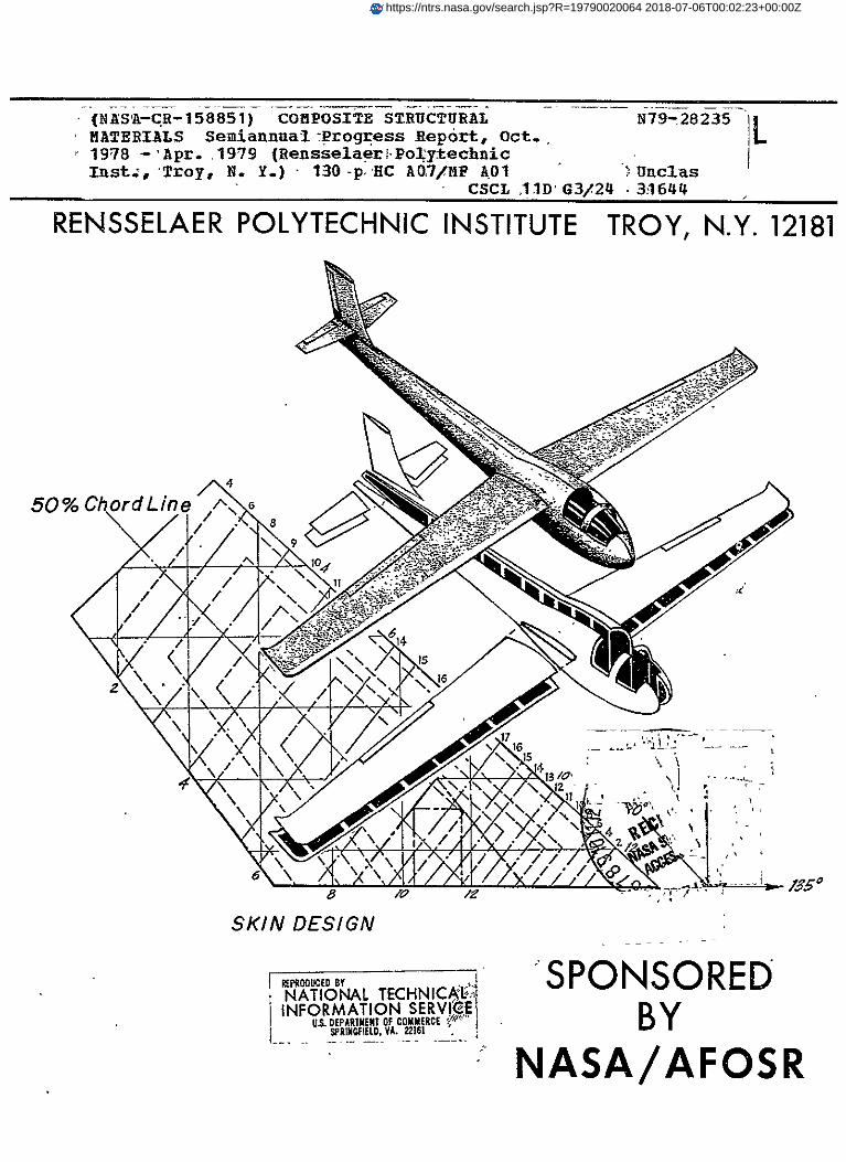
RENSSELAER POLYTECHNIC INSTITUTE TROY, N.Y. 12181
50% ChordLine A.
,/ 17
< 16
47\ ~~13/o , '
SKIN DESIGN
V..,'SPONSORED,PROC,0, NATIONAL TECHNICAI-INFORMATION SERVICE'
U.. DEPARMENT OFCOMMERCE BYSPRINGFILD. VA.22161
NASA/AFQSR
https://ntrs.nasa.gov/search.jsp?R=19790020064 2018-07-06T00:02:23+00:00Z

Semi-Annual Progress Report
October 1978 - April 1979
COMPOSITE STRUCTURAL MATERIALS
Air Force Office of Scientific Research
and
National Aeronautics and Space Administration
Grant No. NGL 33-018-003
Co-Principal Investigators:
George S. Ansell Dean, School of Engineering
Robert G. Loewy Institute Professor
and
Stephen E. Wiberley Dean, Graduate School and Vice Provost
Rensselaer Polytechnic Institute
Troy, New York 12181
NASA Technical Officer
Le5T-a A. Harris Materials and Structures Division
NASA Headquarters
36th Semi-Annual Report July 1979
CONTENTS
Page
INTRODUCTION .............................................. 1
PART I. CAPCOMP (Composite Aircraft Program Component), N. J. Hoff, Y. Hirano, K. Kenmochi .................. 13
1. The Elevator and Its Attachment ................. 16
2. Berg's Design ..................................... 16
3. Muser's Design ....................................27
4. Supporting Development of Mechanical Joints ..... 42
PART II. CAPGLIDE Composite Aircraft Program Glider), E. J. Brunelle, R. J. Diefendorf, H. J. Hagerup, G. Helwig, N. J. Hoff, C. LeMaistre ..................... 58
1. Wing Group - 12 students ........................ 61
2. Fuselage Group - 6 students ..................... 65
3. Tail Group - 6 students ......................... 65
4. Controls Group - 6 students ..................... 69
5. Engine Group - 2 students ....................... 70
6. Aeroelastic Studies ............................. 70
A. The Basic Boundary Value Problem in Terms of the Elastic Wing .............................. 72
B. Elastic Wing Results .......................... 74
C. Semi-Rigid Wing Results ....................... 76
D. Rigid Wing Results ............................ 77
E. Numerical Results .............................. 78
PART III. COMPAD (Computer Aided Design), L. J. Feeser 95
PART IV. SUPPORTING RESEARCH ........................... 98
Resin Characterization and Optimization, G. Diefen-
Moisture Effects on Composite Structural Materials,
dorf, C. LeMaistre ............................... 99
S. S. Sternstein .................................. 103
Optimization of Laminated Plate Design for Shear, Y. Hirano ............................................ 105
Ultrasonic Non-Destructive Testing Developments, H. F. Tiersten, P. K. Das ........................... 110
CONTENTS (Continued)
Page
Fatigue in Composite Structures, K. Krempl ..... 116
Metal Matrix Composites, N. S. Stoloff ......... 120
PART V. PERSONNEL, AUTHOR INDEX ....................122
PERSONNEL ...................................... 123
AUTHOR INDEX ................................... 126
ii

INTRODUCTION
2
INTRODUCTION
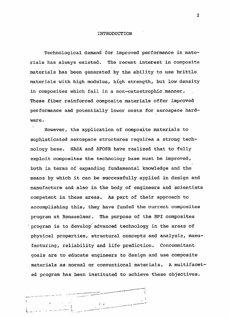
Technological demand for improved performance in mate
rials has always existed. The recent interest in composite
materials has been generated by the ability to use brittle
materials with high modulus, hIgh strength, but low density
in composites which fail in a non-catastrophic.manner.
These fiber reinforced composite materials offer improved
performance and potentially lower costs for aerospace hard
ware.
However, the application of composite materials to
sophisticated aerospace structures requires a strong tech
nology base. NASA and AFOSR have realized that to fully
exploit composites the technology base must be improved,
both in terms of expanding fundamental knowledge and the
means by which it can be successfully applied in design and
manufacture and also in the body of engineers and scientists
competent in these areas. As part of their approach to
accomplishing this, they have funded the current composites
program at Rensselaer. The purpose of the RPI composites
program is to develop advanced technology in the areas of
physical properties, structural concepts and analysis, manu
facturing, reliability and life prediction. Concommitant
goals are to educate engineers to design and use composite
materials as normal or conventional materials. A multifacet
ed program has been instituted to achieve these objectives.

3
The major elements of the program are:
1. CAPCOMP (Composite Aircraft Program Component).
CAPCOMYP is primarily a graduate level project being con
ducted in parallel with a composite structures program
sponsored by NASA and performed by a private, aerospace
manufacturing contractor, the Boeing Commercial Airplane
Company. The main spar/rib region on the Boeing 727 ele
vator, near its actuator attachment point, has been se
lected as the first component for study in CAPCOMP. The
magnitude of the project - studying, designing, fabricating
and testing the most highly stressed region on the eleva
tor - is both consistent with Rensselaer's capabilities,
and a significant challenge. The selection of a portion
of a full-scale flight hardware structure assures relevance
to this project's direction.
Visits to Boeing were conducted in the Fall of 1978 by
Professor Hoff and several of his students, and the first
serious design work began shortly thereafter. Progress on
two alternative designs are reported in Part I.
2. CAPGLIDE (Composite Aircraft Program Glider).
This undergraduate demonstration project is to design,
fabricate and test a foot-launched, ultralight glider using
composite structures. A flight vehicle-was selected to maxi
mize student interest and to provide the students with a
broad-based engineering experience. For those students con
tinuing with graduate work at RPI, CAPGLIDE is intended to
4
provide natural progression to CAPCOMP.- The progress on
the CAPGLIDE project to date has been satisfactory. Four
professors and approximately 31 students were actively
engaged in the project during the beginning of this period;
that is, at the start of the fall semester. A description
of the work performed under CAPGLIDE is given in Part II.
3. COMPAD (Computer Aided Design). A major thrust of
the composites program is to develop effective and efficient
tools for the analysis and design of composite structures.
Rensselaer and NASA Langley have jointly implemented the
use of the SPAR code on minicomputers. This work has been
continued at Rensselaer during the past reporting period to
make "virtual memory" available to those using SPAR. More
complete details are reported in Part III.
4. Composites Fabrication and Test Facility. Struc
tural design engineers, educated only by course work and
design projects limited to paper, often fail to sense or
appreciate problems involved in fabrication. The actual
fabrication and testing of composite structural components
provides this training and the final validation for the de
signs in our CAP projects. PPI's Composites Fabrication
and Test Facility is located in the laboratory and high bay
areas of the Jonsson Engineering Center. Equipment is
available for compression molding parts as large as 19" x
19" and vacuum bagging parts up to 4' x 8'. Ultimately,
panels as large as 5' x 20' will be made by vacuum bagging.
5
A pressure vessel for small parts and spars has been de
signed and was built during the last report period. NASA/
AFOSR approval to order v&rious pieces of specific test
equipment for both materials and components was obtained
during the last period and all deliveries have been made,
increasing significantly our ahilities in fabrication and
testing areas. More complete details are reported in
Part II under CAPGLIDE.
5. Research Programs. The criteria for selection of
research projects to be conducted under this program are
(al that they must anticipate critical problem areas which
may occur in the CAP or NASA/AFOSR programs or (b) that solu
tions to existing problems are not yet satisfactorily in
hand. During the reporting period nine programs were funded;
one has been phased out as we budget for the coming period.
Results from the ongoing projects are reported in Part IV.
6. Curriculum Revisions. The goal of educating engi
neers to think of composites as normal or conventional mate
rials has required changes in curriculum. Since the initi
ation of this program, almost all Rensselaer engineers take
introductory courses which incorporate the concepts of ani
sotropy and composite materials. In addition, six special
ized courses in composites have been offered during the past
three years to develop those special skills required of
students involved in the composites program. A new course
was introduced in the Fall '78 Semester on composite design

6
and analysis using programmable hand calculators, a central
mini and full frame computers. The additions of the SAP and
SPAR computer codes and the growing availability of inter
active computer graphics under our COMPAD program element
are beginning to reach the point where our engineering stu
dents are using these facilities as everyday working tools
for design, analysis and visualization purposes.
7. Technical Interchange.
a) As we approached the end of the reporting period Dr.
Yoichi Hirano was finishing his research at RPI and prepar
ing for return to the University of Tokyo. His stay at RPI
has been most productive, as evidenced by reports on CAPCOMP
and INSURE (Innovation and Supporting Research) in this and
other progress reports. Dr. Gunter Helwig, our first "NASA/
AFOSR Visiting Associate" has been offered and has accepted
an appointment as Assistant Research Professor at RPI. With
this appointment, he has agreed to lead the CAPGLIDE program
element.
b) Technical meetings: Technical meetings, on- and off-campus,
provide important opportunities for interchange of technical
information. Because of the large number of composites meet
ings, a central catalog with all upcoming meetings is being
maintained and distributed periodically. In this way we help
assure that a Rensselaer staff member will participate in
important meetings. The calendar for this reporting period is
shown in Table I. Meetings attended by RPI composites
7
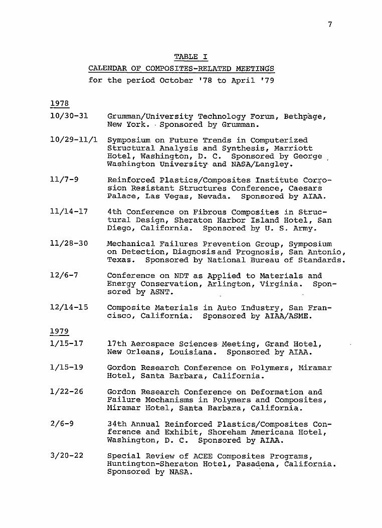
TABLE I
CALENDAR OF COMPOSITES-RELATED MEETINGS
for the period October '78 to April '79
1978
10/30-31 Grumman/University Technology Forum, Bethpage, New York. Sponsored by Grumman.
10/29-11/1 Symposium on Future Trends in Computerized Structural Analysis and Synthesis, Marriott Hotel, Washington, D. C. Sponsored by George Washington University and NASA/Langley.
11/7-9 Reinforced Plastics/Composites Institute Corrosion Resistant Structures Conference, Caesars Palace, Las Vegas, Nevada. Sponsored by AIAA.
11/14-17 4th Conference on Fibrous Composites in Structural Design, Sheraton Harbor Island Hotel, San Diego, California. Sponsored by U. S. Army.
11/28-30 Mechanical Failures Prevention Group, Symposium on Detection, Diagnosis and Prognosis, San Antonio, Texas. Sponsored by National Bureau of Standards.
12/6-7 Conference on NDT as Applied to Materials and Energy Conservation, Arlington, Virginia. Sponsored by ASNT.
12/14-15 Composite Materials in Auto Industry, San Francisco, California; Sponsored by AIAA/ASME.
1979
1/15-17 17th Aerospace SciencesMeeting, Grand Hotel, New Orleans, Louisiana. Sponsored by AIAA.
1/15-19 Gordon Research Conference on Polymers, Miramar Hotel, Santa Barbara, California.
1/22-26 Gordon Research Conference on Deformation and Failure Mechanisms in Polymers and Composites, Miramar Hotel, Santa Barbara, California.
2/6-9 34th Annual Reinforced Plastics/Composites Conference and Exhibit, Shoreham Americana Hotel, Washington, D. C. Sponsored by AIAA.
3/20-22 Special Review of ACEE Composites Programs, Huntington-Sheraton Hotel, Pasadena, California. Sponsored by NASA.

8
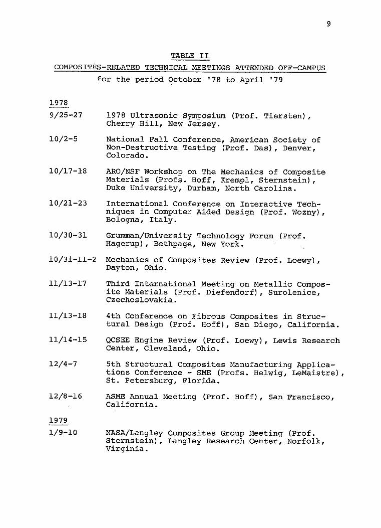
program fatulty/staff during the reporting period are shown
in Table II. Some meetings held on-campus with off-campus
speakers, particularly relevant to composites, are listed in
Table III. A list of composite-related visits to relevant
organizations by RPI faculty/staff/students, with the pur
pose of each visit outlined, is presented in Table IV.
In summary, the NASA/AFOSR Composites Aircraft Program
is a multi-faceted program whereby aeronautical, mechanical
and materials engineers must interact to achieve its goals.
"Hard-nosed" engineering of composite aircraft structures
is balanced against research aimed at solving present and
future problems. In the following sections, detailed de
scriptions of the CAPCOMP, CAPGLIDE, COMPAD and INSURE
programs are presented.
9
TABLE II COMPOSITES-RELATED TECHNICAL MEETINGS ATTENDED OFF-CAMPUS
for the period October '78 to April '79
1978
9/25-27 1978 Ultrasonic Symposium (Prof. Tiersten), Cherry Hill, New Jersey.
10/2-5 National Fall Conference, American Society of Non-Destructive Testing (Prof. Das), Denver, Colorado.
10/17-18 ARO/NSF Workshop on The Mechanics of Composite Materials (Profs. Hoff, Krempl, Sternstein), Duke University, Durham, North Carolina.
10/21-23 International Conference on Interactive Techniques in Computer Aided Design (Prof. Wozny), Bologna, Italy.
10/30-31 Grumman/University Technology Forum (Prof. Hagerup), Bethpage, New York.
10/31-11-2 Mechanics of Composites Review (Prof. Loewy), Dayton, Ohio.
11/13-17 Third International Meeting on Metallic Composite Materials (Prof. Diefendorf), Surolenice, Czechoslovakia.
11/13-18 4th Conference on Fibrous Composites in Structural Design (Prof. Hoff), San Diego, California.
11/14-15 QCSEE Engine Review (Prof. Loewy), Lewis Research Center, Cleveland, Ohio.
12/4-7 5th Structural Composites Manufacturing Applications Conference - SE (Profs. Helwig, LeMaistre), St. Petersburg, Florida.
12/8-16 ASME Annual Meeting (Prof. Hoff), San Francisco, California.
1979
1/9-10 NASA/Langley Composites Group Meeting (Prof.Sternstein), Langley Research Center, Norfolk, Virginia.

10
TABLE II continued.
1979
1/22-25 3rd Annual American Ceramics Society Conferenc( on Composites and Advanced Materials (Prof. LeMaistre), Merritt Island, -Florida.
1/22-26 Gordon Research Conference on Deformation and Failure Mechanisms in Polymers and Composites, (Prof. Diefendorf), Santa Barbara, California.
3/20-22 Special Review of NASA's ACEE Composites Programs (Prof. Helwig), Pasadena, California.
3/28-31 3rd International Symposium on The Science and Technology of Low Speed and Motorless Flight (Prof. Helwig), Langley Research Center, Norfolk, Virginia.

TABLE III ii
COMPOSITES RELATED MEETINGS/TALKS HELD AT RPI
(October '78 - April '79)
Topi Date Speaker (s)
Heat Propagation in Layered Com-posites; A Singular Perturbation Problem
Sep. 20, '78 Gabriel Horvay, Professor, Dept. of C.E., University of Massachusetts
Random Vibration Analysis of Structures and Identification of
Oct. 25, '78 Chung-Bang Yun, Polytechnic Institute of New York
Structural Systems
Finite Element Analysis with Nov. 7, '78 Dennis A. Nagy, Princeton Buckling Mode Superposition University
Gas Turbines - The State of the Nov. 14, '78 Justin Neuhoff, Consultant-Art & What Lies Ahead Engineering Operations, Gas
Turbine Div., G. E. Co.
Mechanical Invention: An Act of Inspiration or a Branch of
Dec. 7, '78 Ferdinand Freudenstein, Prof., Dept. of M.E., Columbia Univ.
Applied Mechanics?
Reliability of Structural Systems Jan. 23, '79 Mark P. Gorman, Case Western Reserve University
Analysis of Hartford Civic Center Roof Collapse
Jan. 26, '79 Howard Epstein, Professor, University of Connecticut
Advanced Prop Fan Development Program
Jan. 29, '79 George E. Clute, Mgr, Product Marketing; and Arthur Jackson, Mgr, Aero Systems Hamilton Standard, Div of UTI
Light-Weight Fabrication Techniques for Wing Structures
Feb. 1, '79 Robert Baucom, NASA Langley
Reliability Evaluation of Exist-ing Structures
Feb. 9, '79 S. J. H. Chen, Purdue University
Development of QCSEE Turbofan Composite Structures
Feb. 19, '79 Robert Stabrylla, Mgr, Composite Blade Design, G. E. Co.
Space Truss Design: The Polyhedral Chain Group
Feb. 27, '79 Martin F. Rooney, Professor, Carnegie-Mellon University
Design For The Prevention of Progressive Collapse Using
Mar. 6, '79 John L. Gross, Cornell University
Interactive Computer Graphics

12
TABLE IV
COMPOSITE-RELATED VISITS TO RELEVANT ORGANIZATIONS
by RPI Faculity/Staff/Students
Visited Date By Prof(sY. Purpose
Cornell University:
Profs. J. Abel L. Phoenix
10/30/78 R. G. Loewy To review computer
graphics, statistical approach to composites strength.
NASA/Langley:
Mr. R. Baucom
12/20/78 N. Hoff To discuss composite
spoiler design for the 737.
U. of Deleware:
Profs. B. Pipes
A. Metzner
12/28/78 R. G. Loewy To discuss program of
the Delaware Composite Center
NASA/Lewis:
Mr. J. Freche
1/8/79 P. Das
H. Tiersten J. McDonald
To discuss NDE tech
niques.
MacD.D.A.C.:
Mr. P. Fleet-
wood
1/10/79 P. Das
H. Tiersten J. McDonald
To discuss NDE tech
niques.
NASA/Langley:
Mr. B. Stein
1/10/79 E. Krempl
N. Stoloff S. Sternstein
To discuss fatigue and
fracture mechanism composites.
NASA/Langley:
Mr. P. Hanson
1/11/79 E. Brunelle To review developments
in composite aeroelasticity.
Boeing Com. A.C.:
Mr. S. Harvey
1/11/79 P. Das
H. Tiersten J. McDonald
To discuss NDE tech
niques.

13
PART I
:APCOMP (Composite Aircraft Program Component)

14
CAPCOMP (Composite Aircraft Program Component)
(N. Hoff, Y. Hirano, K. Kenmochi)
CAPCOMP is a program to design flight critical struc
tures to take the maximum advantage of composite materials.
By combining the efforts of experienced faculty with bright
and well trained but inexperienced graduate students in an
environment relatively free of traditional design and manu
facturing processes, we hope to devise new and hopefully
useful design concepts.
There is sufficient information available today to
prove that many structural elements can-be built lighter
of advanced composites than of metals. But if such elements
have to be joined by any other method than adhesive bonding,
difficulties and uncertainties arise which can be eliminated
only through conservative designs with their attendant
penalties in weight or by extensive and expensive programs
of "cut and try". This stands as one important impediment
to full adoption of composites by the aerospace industry.
On the basis of these considerations Rensselaer Poly
technic Institute began, as the first task aimed at new
structural concepts r the design using composites of a joint
used in an airplane elevator. To make the design realistic,
an existing metal airframe component was chosen for redesign
in composites. The existing design chosen was that of the
Boeing 727 elevator actuator attachment. We conceive of
15
this work as carrying forward a Structures Demonstration
Program using the joint of the 727 elevator, in parallel
with NASA and its aerospace engineering contractor, the
Boeing Commercial Airplane Company. Our design, fabrication
and test effort will emphasize design ideas specifically
suited to advanced composite construction for the purpose
of minimizing the weight of the structure, but on a scale
consistent with the university context and funding level.
The staff of RPI is very grateful to the Boeing Aircraft
Corporation and its engineers for their wholehearted support
of the work at RPI.
During the reporting period, two different designs
suitable for replacing the largely metal attachment produced
by Boeing were begun. The first and more conservative made
use of quasi-isotropic graphite-epoxy laminates; it was de
veloped by R. W. Berg, a graduate student. A second grad
uate student, Christoph Muser, developed a second design in
which a conscious attempt was made to use uniaxial graphite
epoxy tape to as great extent as possible- Both men carried
out their designs, analyzed them, built parts of them, and
tested representative sub-structures.
A third graduate student, Wonsub Kim, with the help of
Research Associate, Kiyoshi Kenmochi, built tensile test
specimens with empty or loaded circular holes to determine
the most efficient arrangement of the fibers around the
hole. The two men have been using photoelastic equipment

16
to find strain concentration factors. This work is largely
in support of the design effort of Berg and Muser.
The entire work here described has been directed by
Dr. Nicholas J. Hoff, Clark-Crossan Professor of Engineering.
1. The Elevator and Its Attachment
The conventional aluminum alloy elevator of the Boeing
727 is shown in the upper half of Figure 1. The lower half
of the figure is the new version of the elevator redesigned
by Boeing in graphite epoxy; it is evident from the pictures
that the latter is composed of fewer parts than the former.
However, the actuator fitting of the new'design is still
manufactured of aluminum alloy. This fitting is shown in
Figure 2. The fitting is attached to outboard and inboard
portions of a new graphite-epoxy spar and to a graphite
epoxy nomex-honeycomb rib as indicated in Figure 3.
The attachment was designed by Boeing to carry loads
up to 19,000 lbs. The direction of the load varies as the
elevator rotates over an angle of 28 degrees from the full
down to the full-up position.
2. Bergt s Design
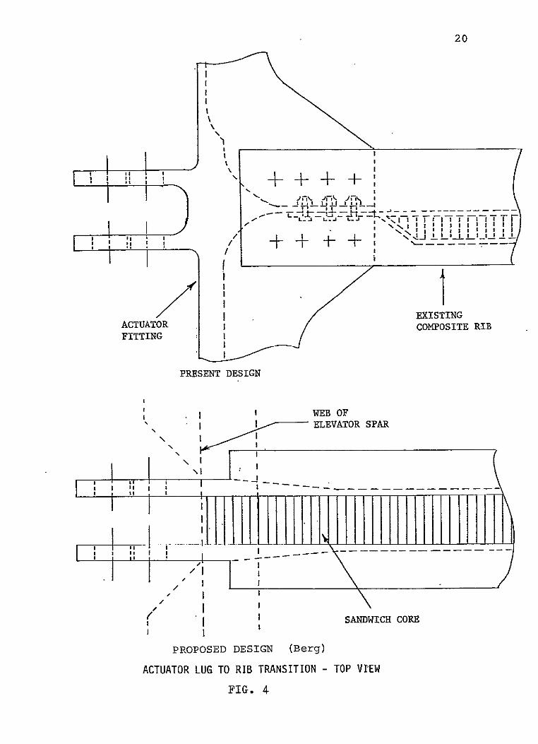
Berg's design is shown in Figures 4, 5 and 6. The
first of these figures compares the Boeing composite design
with Berg's design; both are shown. Figure 5 is an axono
metric view of Berg's original design; it shows the

17
BALANCE PANELS
BALANCE WEIGHT
-LOWER SKIN PANEL
Conventional Aluminum Elevator
SUpPPR 1401Jryt0115 SKIN
CONTROL TAB
ExisTING
ACTUATOR ALUMI MUM
AREAS
Advanced Composite Elevator
BOEING ELEVATOR ASSEMBLY
Fig. 1

ALUMINUM ACTUATOR FITTING (Boeing Design)
SrFOR RnUM
CL G. 2CCTg a

inboard spar (graphite epoxy)
actuator rib
(graphite epoxy)
COMPOSITE ELEVATOR ACTUATOR ASSEMBLY (Boeing Design)
Fig. 3
20
N
i I
IIN
A I C I
FITTING'I " I"' N
PRESENT DESIGN
IS ISIN
I WEB OF I I ELEVATOR SPAR
ACTUATORWIC COMPSEI S ; I I
J -- - -IW
-
-- - - - -
"I I PRPSET DESIGN (eg
I / I I
- I
PROPSEDDESIGN (Berg)
ACTUATOR LUG TO RIB TRANSITION - TOP VIEW
FIG. 4

FIRST CUT 'ACTUATORRIB (Berg Design)
(Assembled Rib)
m
FIG. 5

PROPOSED SPAR AND RIB ASSEMBLY (Berg Design)
Actuator Rib
Elevator Spar
a 0 0 NOTE: Two lugs on actuator rib 7 are inserted through slots
in web of elevator spar for assembly.
to
FIG. 6

23
substantial build-up of thickness in the lug areas to pro
vide the required bearing strength. The number of graphite
epoxy layers decreases with distance from the bolt holes.
Figure 6 shows how the spar and new acturator rib would be
assembled. It will be noted that the edges of some of the
layers are bent 90 degrees to fbrm flanges to which the
upper and lower coverplates of the elevator can be attached.
Attachment would be by means of titanium Hi-Loc fasteners.
The right-hand and left-hand graphite-epoxy webs are stabil
ized by a layer of nomex-honeycomb between them.
After an approximate preliminary analysis, a computer
program for a more accurate finite-element analysis of the
actuator rib web (including the areas of the lugs with the
bolt holes) was developed, The main objective of the anal
ysis was to examine the stress distribution in the area of
the holes and the way these stresses transfer loads to the
flanges of the actuator rib. Thus, in the first computation
the wall thickness of the actuator rib web was taken as
constant. Forces were introduced as they would be through
the actuator and reaction links (see Figure 21, simulating
bolt loads. The reacting torque, as would result from aero
dynamic forces on the elevator, was represented by distrib
uted shear flow along the upper and lower edges of the
actuator rib. The finite-element model contained 482 nodes
and a total of 800 quadrilateral and triangular elements;

24
its length is 60% of the full length of the rib, the same
length as the Boeing test specimen.
The results of the finite-element computations are the
stress levels shown in Figure 7. As expected, there are
high stress levels around both bolt holes, but unexpectedly
lower levels between the holes, The stresses continue from
the upper hole rearward on the upper rib flange at higher
levels than first predicted. On the basis of these results,
the thickness distribution of the web of the actuator rib
was modified as shown in Figure 8.
A concurrent series of experiments were performed to
obtain data on the strength of the composites to be used.
Four simple test specimens, 7" long, 2" wide and 0.22" thick,
were manufactured of 00, ±45', 900 graphite-epoxy tape.
They were loaded through two holes, 1/2" in diameter, using
an Instron testing machine. Among the more interesting
test results is the fact that the maximum circumferential
strain around the hole was found to be three times the
average strain; this is in good agreement with predictions
from the theory of isotropic plates. The quality of the
specimens improved as experience was gained in their fabri
cation. The three best specimens failed in bearing. Even
among these, however, failure loads varied from 2800 lbs.
for the first, to 8800 lbs. for the last of these. The
difference is attributed to quality of the holes; the first
two of these three specimens were drilled with a high-speed
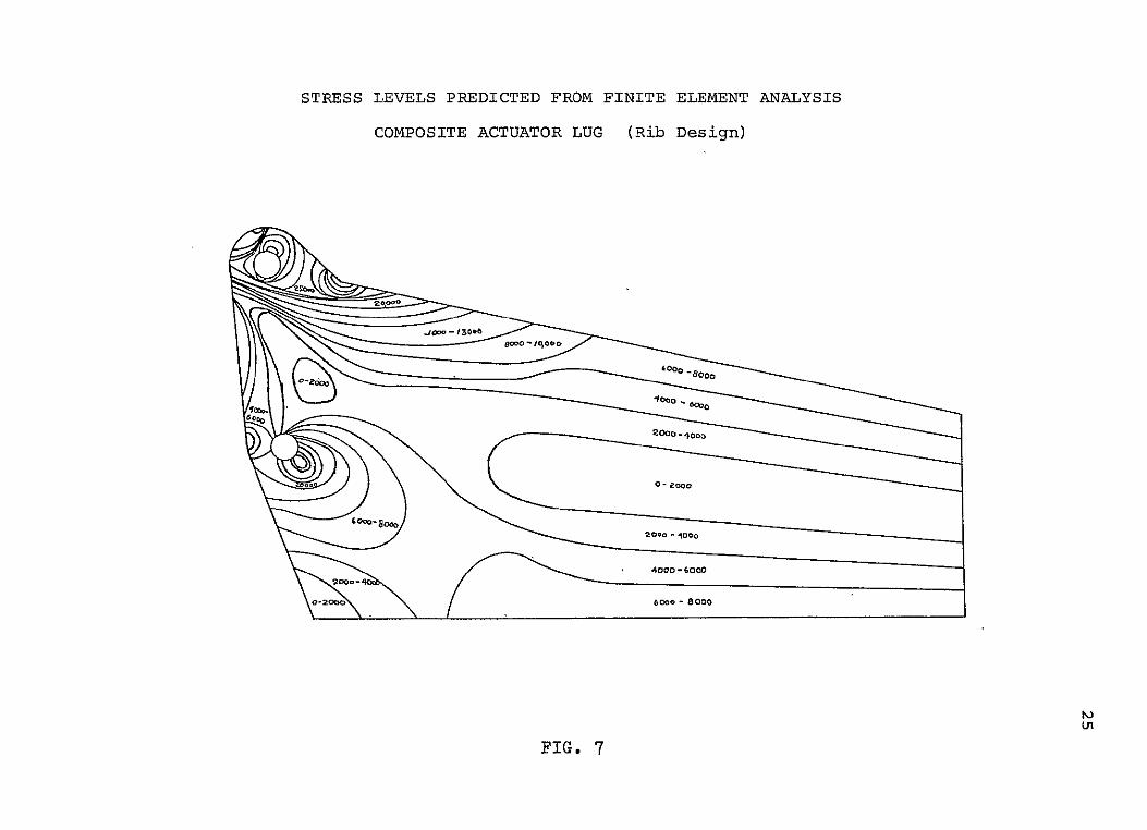
STRESS LEVELS PREDICTED FROM FINITE ELEMENT ANALYSIS
COMPOSITE ACTUATOR LUG (Rib Design)
4000 -80
QOa -0 .c
60o0 - 8000
FIG. 7
FIG. 7

ACTUATOR RIB MODIFIED FQLLOWING FINITE
ELEMENT ANALYSIS (Berg Design)
FIG. 8
27
steel bit Which caused delamination between layers of the
composite around the hole. The last specimen was drilled
with a carbide-tipped drill bit, which resulted in much less
delamination. The difficulties in eliminating delamination
completely from drilled holes can be appreciated from our
Table V; this is reproduced from Reference 1.
As each actuator rib contains two webs with two lugs
and holes, the ultimate load the rib could carry is 2 x
8800 = 17,600 lb., which amounts to 93 percent of the requir
ed failure load.
Details of the test set-up are shown in Figure 9.
Figure 10 is an enlarged photograph of the bearing failure
of Specimen 3.
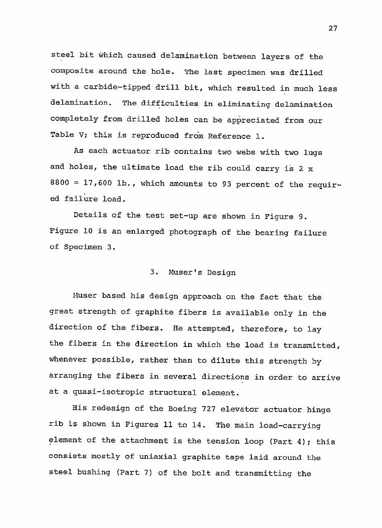
3. Muser's Design
Muser based his design approach on the fact that the
great strength of graphite fibers is available only in the
direction of the fibers. He attempted, therefore, to lay
the fibers in the direction in which the load is transmitted,
whenever possible, rather than to dilute this strength by
arranging the fibers in several directions in order to arrive
at a quasi-isotropic structural element.
His redesign of the Boeing 727 elevator actuator hinge
rib is shown in Figures 11 to 14. The main load-carrying
element of the attachment is the tension loop (Part 4); this
consists mostly of uniaxial graphite tape laid around the
steel bushing (Part 7) of the bolt and transmitting the

28
THICKNESS DRILL SPEED FEE TRACER MATERIAL IN. TYPE tit D j pr RADIOGRAPHY PENETRANT COMMENTS
GRAPHITE/J 0.300 lIBDIA 6000 0.001 0 20" - 0 C SMALL HOLES ALLHOLES FAIRLY SMOOTH. ALLEPOXY ROTA-KOTE OELAMINATI.N OIFFICULT TO TEST. - HAVE BREAKOUTS PROGRESSIVELY
ON ALL HOLES MANY INDICATION WORSTENING TO LAST HOLE DRILLMARKSGIVE FALSE POSITIVES
GRAPHITE! 0.300 3116IOTA 6000 0001 0-0200" FIRST HOLES FAIRLYSMOOTH BUT EPOXY ROTA-KOTE DELAMINATION BECOME ROUGHER ALL HOLES HAVE
CARBIDE ON ALL HOLES BREAKOUT WITH CONDITION WORSE TOWARD LAST WORSTENING AT LAST SOHOLES
GRAPHITE/ EPOXY
0.25 15/16DA DIAMOND-
6000 0.001 ALL HOLE DELAM. INATEDO .100".125"
HOLES FAIRLY SOOTH,LITTLE BREAKOUT
TIPPED (80-IC GRITI
GRAPHITE/ 0.275 114lIA 600 0.001 ALL HOLES UEAM. HOLES CLEAN; MINOR BREAKOUT EPOXY DIAMOND- INATEDOS"-0.125" ON LASY PLYS
TIPPED ± 2 GRIT) 1 BREAKOUT AND
GRAPHITE/ 0.275 114DIA 6000 001 ALL HOLES DELAMINATION MINOR FIBER PULLOUT IN LAST EPOXY DIAMOND. DELAMINATED CAN BESEEN THREE HOLES, MINOR BREAKOUT
TIPPED r 0.50 - 0 I30" AT BOTTOM OF (I00-120 GRIT)
7 1 HOLE MANY FALSE POSITIVES
GRAPHITE! 0275 114DIA 6000 0001 ALL HOLES FIBER PULLOUT IN ALL HOLES; EPOXY CARBIDE- DELAMINATED 0.010" BREAKOUT INCREASES AS NO. OF
TIPPED 0.075"NO HOLES INCREASESOME DELAMINATION RELATIONSHIPTO ON ENTRANCE SIDE NUMBER OFHOLES DRILLED
GRAPHITE/ 0.300 114CIA 6000 0001 ALL HOLES FIBER PULLOUT BECOMESPROGRESSIVELY EPOXY MICROGRAINED
CARBIDE DELAMINATED O-0.125" DELAMINATION
WORSEWITH INCREASED HOLE NUMBER NO SIGNIFICANT BREAKOUT FOR FIRST
WORSTENING FROM 20 HOLES THEN BREAKOUT INCREASES HOLE 1 o60 TO LAST HOLE
GRA"FIITEI 0.27$ 1/4DIA 6000 0.001 ALL HOLES FIBER PULLOUT IN ALL HOLES. MINOR EPOXY FISHTAILPOINT. DELAMINATED 0.055" - BREAKOUT FROM ALL HOLES
CARBIDE. 0130" TIPPED
GRAPHITE/ 0.300 118CIA 6000 0031 DELAMINATION MANY INDICATORS SOME FIBER PULLOUT, BAD EPOXY ROTA-KOTE AND BREAKOUTON HOLES SMALL TO BREAKOUT ON ALL HOLES
HSS ALL HOLES TO 0.125" TEST ACCURATELY I MAX.
GRAPHITE/ EPOXY
0.275 0 190DIA ROTA-KOTE
6000 0001 ALL HOLES DE-LAMINATED0.110"-
SOME FALSE INDICATIONS
HOLES FAIRLY SMOOTH SOME FIBER PULLOUT BREAKOUT ON
HSS 0.140" ALL HOLES,
GRAPHITE! 0.270 0.26 DIA 3000 0.003 DELAMINATION OF MATERIAL IN HOLE SMOOTH AT FIRST PROGRESSIVELY EPOXY TWIST HSS HOLE 1 OF .120"
PROGRESSING TO 0.150" HOLE HOLDSPENETRANT, FALSE
GETTING ROUGHER 0 HOLE 14. BADBREAKOUT ON ALL HOLES
AT LAST HOLE INDICATIONS
GRAPHITE! 0.270 0.250 CIA 6000 0.003 DELAMINATION IN ALL HOLES FAIRLY SMOOTH Of EPOXY TWIST HSS ALLHOLES SOMEQUALITY THROUGH ALL
0.120" - 0.150" SIX SOME FIBER PULLOUT, BAD BREAKOUT ON ALL HOLES
GRAPHITE/ EPOXY
0.270 0.250 CIA CARBIDE
6000 0.001 ALL HOLES DELAMINATED
HOLE OUALITY ESSENTIALLY THE SAME THROUGH OUT ALL 60
TIPPED 0120" - 0.50" HOLES. BREAKOUT ON ALL HOLES. SOME GOUGING BY DRILL
GRAPHITE! 00.270 D.BODIA 6000 0001 HOLES DELAMINATED HOLE DUALITY SIMILAR FOR EPOXY CARBIDE 0.080" ALL 140 HOLES ALL HOLES
DRILLIC'SINK DELAMINATED WITH BREAKOUT. Zl14104 0.2055 DlA
GRAPHITE/ EPOXY
.7 MEGADIAMOND TIPPED
25M 0=1 4500
DEMINA"ION AT HOLE I of .120"PROGRESSING TO 0.150"
HOLE OUALITYTHE SAME FOR ALL6OHOLES SOME FIBER PULLOUT, ALL HOLES HAVE BREAKOUT
AT HOLE #60
GRAPHITE/ EPOXY
.75 0250DIA TWIST.
21.800 0.001 DELAMINATIONAT HOLE # 1 OF 0.005"
PENETRANT GIVESMANY
FAIRSURFACEFINISHINALL 120 HOLES. ALL HOLES HAVE
CARBIDE PROGRESSING TO 0.125" FALSE POSITIVES BREAKOUT
TIPPED - AT HOLE # 120
GRAPHITE! 0.275 0 ISODIA 21,000 0.001 DELAMINATION AT HOLE FAIR SURFACE FINISH IN ALL EPOXY CARBIDE # IOF .OS PROGRESSING 250 HOLES ALLHOLES HAVE
ZI4I104 TOO.130"ATLAST BREAKOUT INGLE .#250
TABLE V Summary of Non-Denructivo Evaluation of Drilled Holes
and(Reproduced from Manufacturing Methods for Cutting, Machining Drilling Composites, Volume II - Tests and Results, AFMk-TR-78-lU3 Vol. II, August 1978.)

29
SPECIMEN IN TESTING MACHINE
FIG. 9

BEARING FAILURE OF SPECIMEN 3
............ ....I~iH.........................................
j(A)
FIG. 10

COMPOSITE ACTUATOR FITTING
(Muser Design)

EXPLODED VIEW
(Muser Design)
\ // / 1. Lug Insert 2. Graphite Epoxy Face
3. Honeycomb Core 4. Graphite Epoxy Tension Loop
. r., Epoxy Compression Member
.BalsawoodCoreSteel Bushing • 8. Graphite Epoxy Cover
FIG. 12
Triple-U
I +
TrpeUTriple-U
+. . . . .. +
Section A-A
Section B-B f
1
2
FIG. 13 DETAILS OF THE DESIGN (Muser)

THREE-VIEW DRAWING (Muser Design)
C4'-
I..1±4
F +
26.o
FIG. 14 iJ

35
actuator load to the upper and lower flanges of the actuator
rib. From these flanges the load is transmitted to the
upper and lower cover plates of the elevator by means of
titanium Hi-Loc connectors. The distance between branches
of the loop is maintained by graphite-epoxy compression mem
bers (Part 5) and a balsawood core (Part 6) sandwiched be
tween them. A few layers of ±450 graphite-epoxy tape placed
between the 0 layers of the tension loop stabilize this
structural element and prevent the cracking of the matrix
and the separation of the fibers under both tensile and com
pressive loads, but particularly the latter.
Since there are two upper and two lower lugs in the
actuator attachment, there are four tension loops in all.
One upper and one lower loop form the main load-carrying ele
ments of each of the right-hand side and the left-hand side
of the (double) actuator rib visible in Figure 11 and in
Section A-A of Figure 13. Each side is covered with graphite
epoxy faces (Part 2) and the faces are stabilized by a honey
comb core (Part 3). The right-hand and left-hand sides of
the actuator rib are attached to each other by the Triple-U;
this is the prefabricated combination of graphite-epoxy U
and channel sections visible in Section A-A of Figure 13.
To check the feasibility of the design, a simplified
model of the tension loop was designed, built and tested.
The specimen is shown in the drawing of Figure 15. The
reference numbers in the figure have the same meaning as in
Figure 12.
TEST SPECIMEN 1
00
70
(7878)
Ir6 -l
0.37S
lay-up tensile loop: 23x00
compression member: 2i±45P/4xCP/4505xOO;457cor4
FIG. 15

37
The tension loop was made of 23 layers of Fiberite
Hy-El048AE prepreg. The layup differed from that described
earlier as all fibers ran in the 00 direction and ±450 fibers
were not included. The prepreg carbon tape in our stores
was quite wide, and frugality dictated that, rather than
taking one long thin strip, a series of shorter strips be
used requiring overlapping of layers. Some of these occurred
near the steel bushings. It is possible that these irregu
larities in geometry contributed to the relatively low value
of the failure load, as described in the following paragraphs.
During the manufacturing process the two steel bushings
of the specimen were fixed to a flat steel plate. This was
the tool for the layup and for the curing process. A dam of
silicone rubber was built around the graphite piece and the
assembly was covered with a vacuum bag. The specimen was
cured in an autoclave at a maximum curing temperature of
2501F and an applied pressure of 85 psi.
The shape of the final specimen was not satisfactory.
The core was crushed along a line and the hoop layers trans
lated laterally because of the weakness of the dam. As a
consequence the piece did not have the exact rectangular
cross section shown in the drawings. This can be seen from
the photographs (Figures 16 and 17). The specimen was tested,
nevertheless, partly to find its strength and partly to gain
experience in testing.

38
UNDAMAGED END OF SPECIMEN
(one quadrant removed)
0 05 1. 15
FIG. 1
CROSS SECTION 0F SPCMN
40 05 1.0
FIG. 17

39
Figure 16 shows the undamaged end of the specimen out
of which one quadrant was cut. Figure 17 is a cross section
of the middle of the specimen which was sawed in two after
the completion of testing. Figure 18 shows the tension
failure at one side of one of the holes.
The test specimen was subfected to tension in an Instron
testing machine, Model 1333. Weak crackling noises were
heard at a very early stage of the loading (around 2500 lb.)
and then again near the maximum load. The specimen broke
suddenly with a big bang after it had withstood a load of
8755 lb. for two or three seconds. One side of the specimen
opened up into the shape of a hook, but it snapped back when
the load was removed. The failure was clearly of the tensile
type, without any deformations due to bearing stresses.
As the design ultimate load of one lug was 9500 lb., the
specimen withstood 92% of the design ultimateload. The
addition of two or three layers of 0* tape would bring up
the strength of the design to the desired ultimate strength.
However, if the efficiency of the design is defined as the
average stress (load divided by cross-sectional area) divided
by the ultimate tensile stress aTU of the material, the de
sign is not very efficient. The area of the cross section
that failed in tension was 2 x 0.126 x 0.375 inches = 0.0945
inches squared. For the ultimate load of 8755 lbs., this
gives an average failure stress of 92,857 psi. Since the
ultimate tensile stress of the material (uniaxial filament
40 TENSION FAILURE
0 0.5 1.0 .15
FIG. 18
SPECIMEN 2 AND MANUFACTURING TOOL
FIG. 19
41
tape) is listed as 160,000 psi, the efficiency of the design
is n = 0.58.
Some increase over the average stress corresponding to
a uniform distribution over the cross section was expected
for the stress near the bolt hole. The efficiency value of
0.58 corresponds to a stress-concentration factor of 1.72.
An effort was made to reproduce this value theoretically,
but without success. Calculations based on the theories of
curved bars and circular rings all yielded much higher stress
concentration factors, probably due to the fact that the dis
tribution of loads as applied in these calculations are un
satisfactory representations of the conditions prevailing in
the test. This theoretical effort continues.
Concurrent with the theoretical analyses, a second
specimen was designed and constructed. In this design the
closed tensile loop concept was dropped in favor of an open
loop. A straighter tape layup was thereby achieved through
the application of tension in forming the loop. The tool
has the exact measurements the specimen should have after
curing. It has a movable top which attains its proper final
position when pressure is applied. A thin aluminum alloy
strip presses the layers of the loop against the tool and
against the compression members. Photographs of the tool and
the specimen are shown in Figure 19.
Unfortunately, the vacuum bag broke in the autoclave
during the curing process, and this specimen was not cured

42
properly. It was decided not to test this specimen. How
ever, the proper shape was obtained, as can be seen from
Figure 19, which shows both the specimen and its manufactur
ing tool. The experimental work will continue using the
revised fabrication concept.
4. Supporting Development of Mechanical Joints
The supporting effort made by Research Associate, Kiyoshi
Kenmochi and Graduate Student, Wonsub Kim had as its purpose
the development of equipment and methods to determine the
stress distribution and the stress concentration factors in,
and the failure modes and failure loads of, simple structural
joints made of advanced composites.
At first, experience was gained in manufacturing flat
graphite-epoxy sheets of Hy-E1048AE prepreg tape with various
combinations of fiber direction in a press with a heated
platen. The tension test specimens were cut from these
sheets on a band saw with carbide dust saw blade. The edges
were finished with sandpaper.
Great difficulties were encountered in drilling holes
in these specimens because it was impossible to avoid delami
nation and some broken fibers at the edge of the hole when
HSS (high-speed-steel) twist drill bits were used. Moreover,
the average life of the drill bit was two holes. The drill
was driven at speeds varying from 120 to 5500 rpm.
43
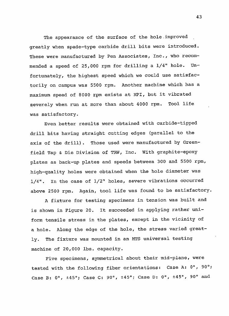
The appearance of the surface of the hole improved
greatly when spade-type carbide drill bits were introduced.
These were manufactured by Pen Associates, Inc., who recom
mended a speed of 25,000 rpm for drilling a 1/4" hole. Un
fortunately, the highest speed which we could use satisfac
torily on campus was 5500 rpm. Another machine which has a
maximum speed of 8000 rpm exists at RPI, but it vibrated
severely when run at more than about 4000 rpm. Tool life
was satisfactory.
Even better results were obtained with carbide-tipped
drill bits having straight cutting edges (parallel to the
axis of the drill). Those used were manufactured by Green
field Tap & Die Division of TRW, Inc. With graphite-epoxy
plates as back-up plates and speeds between 300 and 5500 rpm,
high-quality holes were obtained when the hole diameter was
1/4". In the case of 1/2" holes, severe vibrations occurred
above 2500 rpm. Again, tool life was found to be satisfactory.
A fixture for testing specimens in tension was built and
is shown in Figure 20. It succeeded in applying rather uni
form tensile stress in the plates, except in the vicinity of
a hole. Along the edge of the hole, the stress varied great
ly. The fixture was mounted in an NTS universal testing
machine of 20,000 lbs. capacity.
Five specimens, symmetrical about their mid-plane, were
tested with the following fiber orientations: Case A: 0', 90°;
Case B: 00, ±450; Case C: 90', ±450; Case D: 00, ±450, 900 and

44
FIXTURES FOR TESTING SPECIMENS IN TENSION
(for photoelastic test)
FIG. 20
45
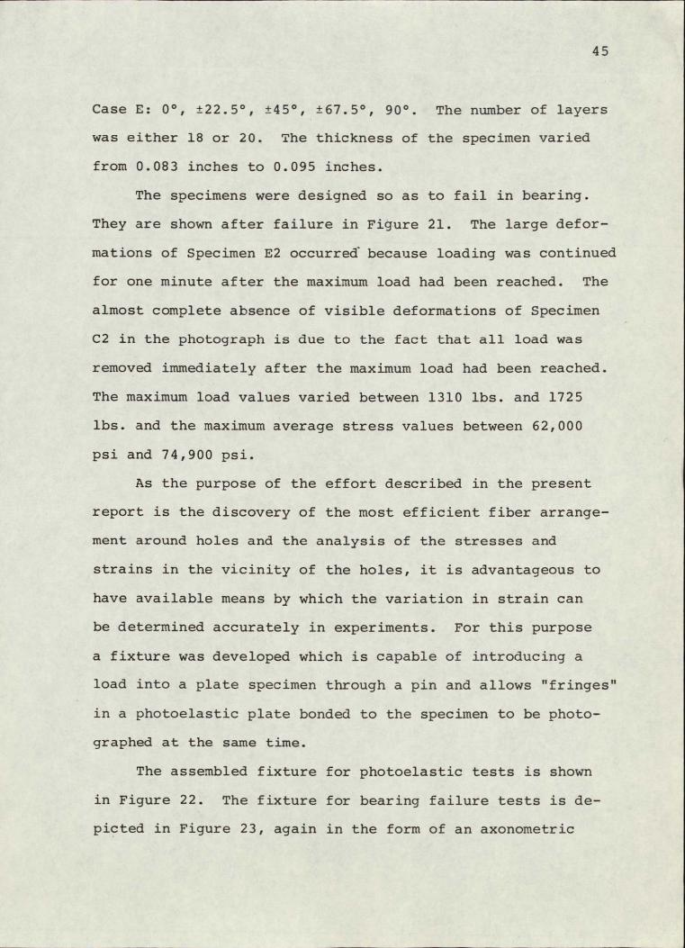
.Case E: 00, ±22.50, ±450, ±67.50, 900 The number of layers
was either 18 or 20. The thickness of the specimen varied
from 0.083 inches to 0.095 inches.
The specimens were designed so as to fail in bearing.
They are shown after failure in Figure 21. The large defor
mations of Specimen E2 occurred because loading was continued
for one minute after the maximum load had been reached. The
almost complete absence of visible deformations of Specimen
C2 in the photograph is due to the fact that all load was
removed immediately after the maximum load had been reached.
The maximum load values varied between 1310 lbs. and 1725
lbs. and the maximum average stress values between 62,000
psi and 74,900 psi.
As the purpose of the effort described in the present
report is the discovery of the most efficient fiber arrange
ment around holes and the analysis of the stresses and
strains in the vicinity of the holes, it is advantageous to
have available means by which the variation in strain can
be determined accurately in experiments. For this purpose
a fixture was developed which is capable of introducing a
load into a plate specimen through a pin and allows "fringes"
in a photoelastic plate bonded to the specimen to be photo
graphed at the same time.
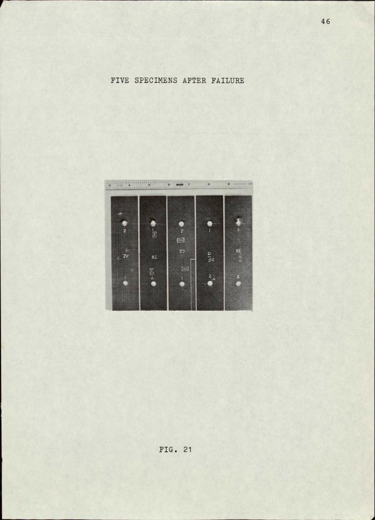
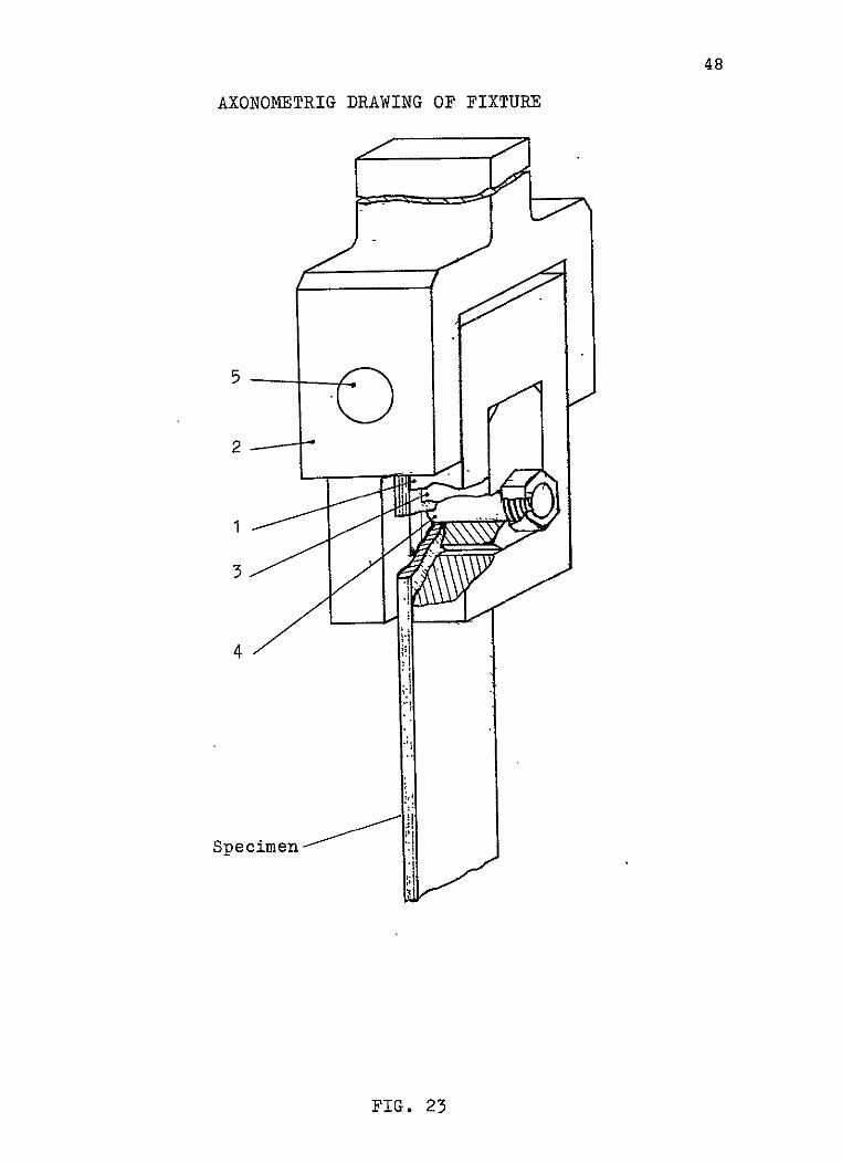
The assembled fixture for photoelastic tests is shown
in Figure 22. The fixture for bearing failure tests is de
picted in Figure 23, again in the form of an axonometric
46
FIVE SPECIMENS AFTER FAILURE
FIG. 21
47 ASSEMBLY OF FIXTURE FOR PHOTOELASTIC TESTS
sheet-Se,-
*> ?e' fmen m~j
--- AW
FIG. 22
48
AXONOMETRIG DRAWING OF FIXTURE
2
4
Specimen
FIG. 23
49
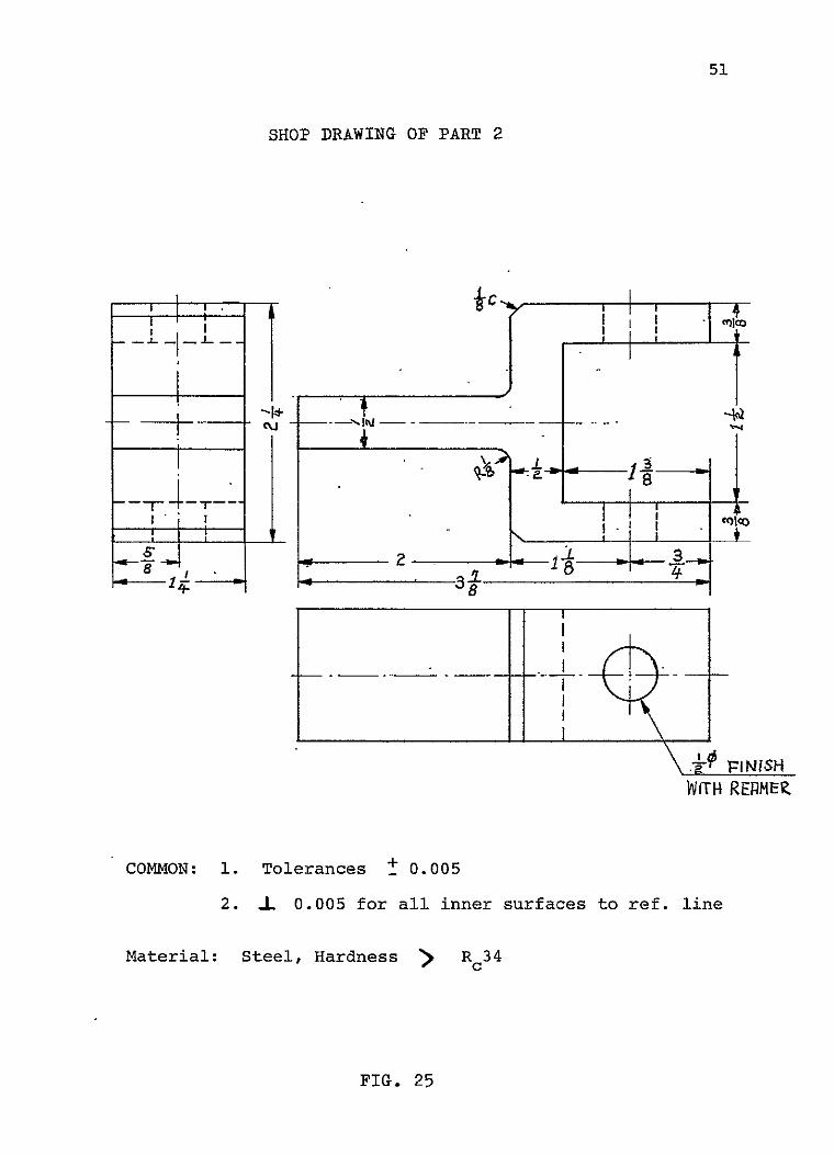
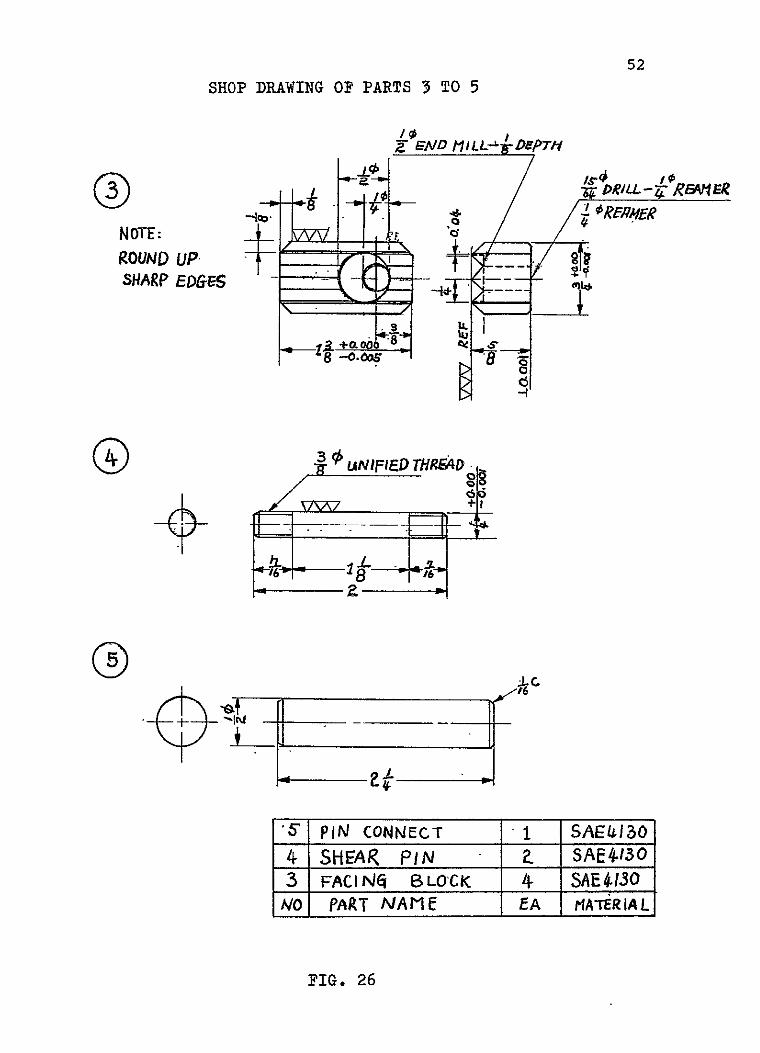
drawing. The numbers in Figure 23 refer to the parts whose
workshop drawings are presented in Figures 24 to 27.
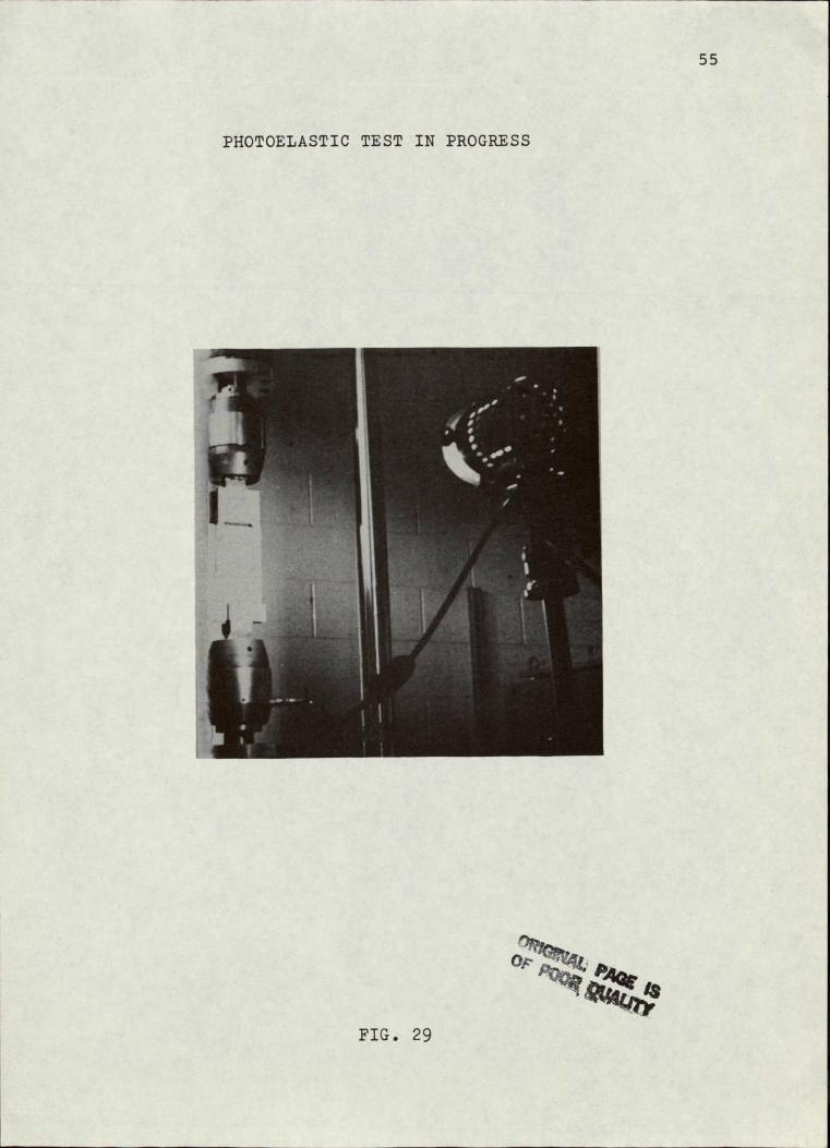
The photoelastic test jig is shown on the workshop
drawing in Figure 28, and Figure 29 is a photograph of a
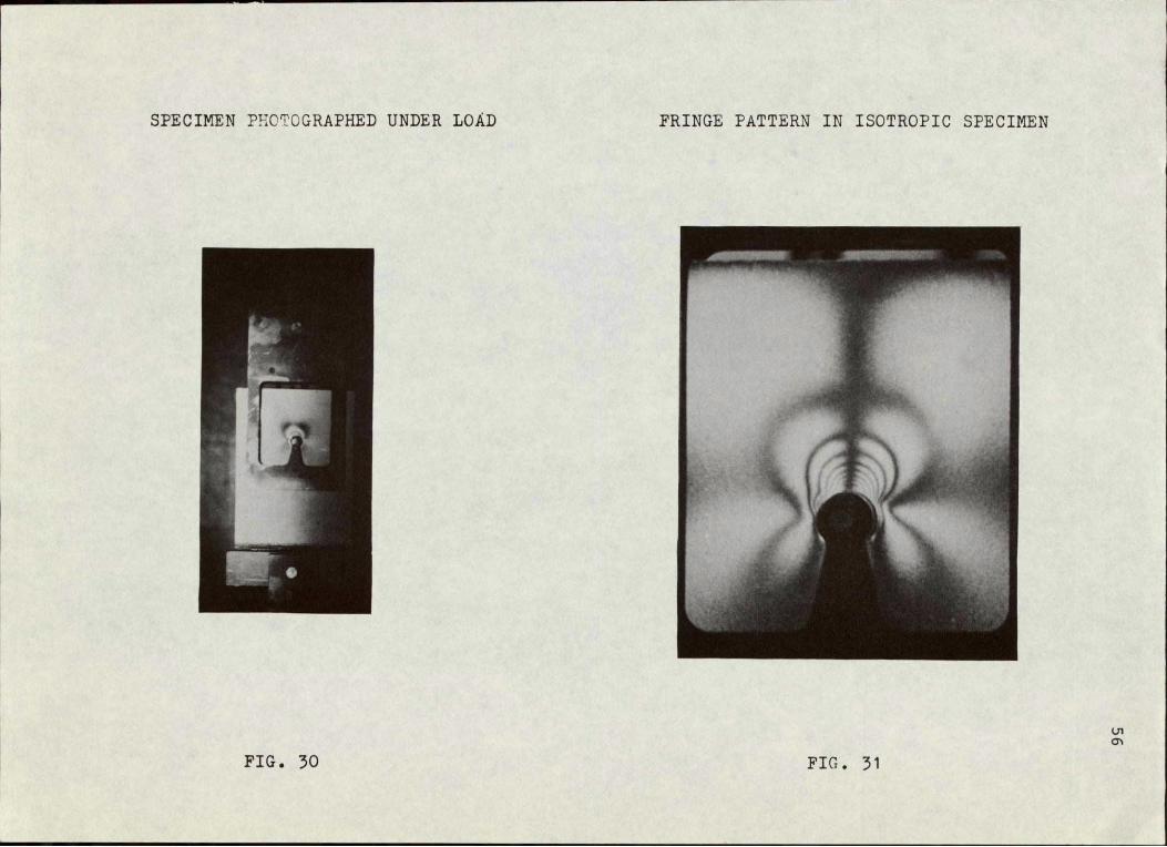
photoelastic test in progress. Figure 30 shows in detail
the test specimen and the fringes in the photoelastic plate
bonded to the specimen. Figure 31 is a close-up of the
specimen with its fringe pattern; this picture was taken
with an isotropic test specimen.
.Difficulties, not yet -overcome, have arisen in drilling
holes in the plate with photoelastic sheets on it. The se
lection of the material of the photoelastic plate and of its
thickness is important because the number of fringes depends
on it. Good drilling procedures are equally important.
Without them, prefringes develop in consequence of residual
stresses or delamination of photoelastic sheets from the
specimen. Uneven spots on the surface of the hole and delami
nation of the test specimen itself can disturb the fringe
pattern caused by the load.
The photoelastic equipment used in the tests consisted
of a polariscope (Model 031, Photolastic Inc.), a specially
prepared test fixture (Figure 23) and a camera (Nikon FM).
A photoelastic sheet calibrator (Model 010-B, Photolastic
Inc.) and a compensator (Model 232-RE) were used for prepar
ing the tests. For analysis purposes, a strain direction
analyzer was specially designed and fabricated.

50
SHOP DRAWING OF PART 1.
I "
4-V TAP STD
Iw1rt_c r- rt'!- N-. ,
LTfi ''-__
1-14
PRILL--MRE-Af &_
COMMON: 1. Tolerances: 0.001 for all inner surfaces-
+ 0.005 for all outer surfaces to ref. line
2. A_ 0.001 for all surfaces to ref. line
3. V7 all inner surfaces
2 all outer surfaces
Material: Steel, Hardness > Rc 34
Chamfer: All outside corners chamfered by 1/16"
FIG. 24
51
SHOP DRAWING OF PART 2
___________I
r4-T
rINISH
WITH REnMEZ
COMMON: 1. Tolerances + 0.005
2. 1 0.005 for all inner surfaces to ref. line
Material: Steel, Hardness > Rc34
FIG. 25
52
SHOP DRAWING OF PARTS 3 TO 5
Z'END l 1LL- DFpruq
D5EqRiL-7RYR
_ROUND UP, -SHARP EDGES - ".
l-- + . 3 1• I.8 S a
j, UNIIED THR&40
1 SAE/4I0'" PIN CONNECT"
4 SHEAR PIN Z SAE4 SO 3 FACIINr BLOCK 4 SAE4I30
MATER IALNO PART NAME EA
FIG. 26

53
SHOP DRAWING OF PART 6
fI------ ini'----
Lii - I
NOTE SEE PART No. 1
FIG. 27

54
SHOP DRAWING OF PHOTOELASTIC TEST JIG
0.5
2 >
-B /
3I4 4 1-C44
/zas_ / 0.22
0 - I6
.3 111
" flit'
I F
____FIL. 2
55
PHOTOELASTIC TEST IN PROGRESS
FIG. 29
SPECIMEN PHOTOGRAPHED UNDER LOAD FRINGE PATTERN IN ISOTROPIC SPECIMEN
F1
PIG. 30 FIG. 31

57
Plans for future testing of the kind described here to
determine composite laminate bearing stress include correla
tion of failure stresses with delamination patterns around
the holes caused by drilling, as sensed and recorded by
ultrasonic N.D.E. Here again, Table V from Reference 1
suggests the unlikelihood of completely eliminating delamir
nation around drilled holes, so that correlation efforts of
this type seem well advised.
Manufacturing Methods for Cutting, Machining and Drilling Composites, Volume II - Tests and Results, AFML-TR-78-103 Vol. II, August 1978.

58
PART II
CAPGLIDE CComposite Aircraft Program Glider)

59
CAPGLIDE (Composite Aircraft Program Glider)
(M. J. Brunelle, R. J. Diefendorf, H. J. Hagerup, G. Helwig, N. J, Hoff.and-C.,. LeMaistre)
CAPGLIDE is an undergraduate program to design, build
and test advanced composite structures. Students will ob
tain direct "hands-on" experience in advanced composite
structures which can serve as a springboard for the more
sophisticated CAPCOMP projects. In dealing with the design
of a complete vehicle, the effect of any given change on
other aspects must be dealt with. In this way the project
also.requires students majoring in aeronautical, mechanical
and materials engineering to interact in much the same way
as they do in industry.
An ultra-light sailplane was selected as the first
demonstration project because a full scale flight vehicle
would maximize student interest and would be of relative
simplicity and low cost to build. A conventional layout
monoplane with three-axis control resulted in the following
estimated performance:
1) Stall speed, 15 knots, 2) Best glide ration, 17 and
3) Minimum sink rate, 2.0 feet per second.
While the glide ratio of the ultra-light sailplane is simi
lar to that of post World War II utility gliders, the more
important sink rate is in the range of standard class sail
planes.

60
Although comparative theoretical analyses.continue in
some areas, the ultra-light sailplane project has moved from
detail design to a primarily fabrication phase. Student ac
tivity during the present contract period has concentrated
on "hands-on" experience with composite material layups,
adhesive bonding and co-curing of structural parts, with
structural proof-tests of subassemblies and with coupon
tests for process-control and property determination.
In the light of our rapidly accumulating fabrication
experience and test results, some detail design features are
still being modified. However, the important design decis
ions have now been made, and the prototype aircraft is being
built. Construction of the aircraft is on schedule. We
expect that the main airframe components will be finished
by mid-summer, connections and control systems by the end
of summer and that the prototype aircraft will have been
proof-tested and ready for operations in early fall.
During the design phase (extensively reported in earlier
semi-annual reports), the student working teams were organized
according to disciplines. For the production phase, the
teams have been realigned to focus on the individual major
parts of the aircraft. The progress of each working team is
summarized in the following pages.

61
1. Wing Group - 12 students
Female wing-molds, incorporating the external contour
of the top and bottom surfaces of the airfoil, have been
assembled from Formica sheet bonded to a framework of ply
wood and composition board. The Formica surface has been
carefully filled and sanded to the contour of the Wortmann
FX 63-137 airfoil and spray-painted with primer and acrylic
paint. Sections of the molds were used to secure experience
with release agents. Problems were encountered with respect
to interaction between acrylic paint, release agent and the
epoxy resin of the layup. These problems were overcome by
laying-up the skins in two stages. The outside layer of
the skin sandwich is laid-up and cured on a flat polyethylene
sheet, for which there is no need for a release agent. Then,
after the cure is nearly complete, this still pliable half
sandwich is transferred to the wing mold with the laminate
side facing the mold. The inside layer is now added as a
wet layup and vacuum-bagged to complete the sandwich. The
sandwich cures rigid, in the shape of an airfoil contour.
Production of the first full-span wing panels is expected to
begin in late May.
Torsion tests were conducted on three separate three
foot span sections of the wing, primarily for the purpose of
determining the rib spacing required to prevent panel buck
ling.

62
Carbon flanges for the prototype wing spar were produced
in the RPI designed 22 foot, temperature-controlled pressure
vessel. The final flange design for the spar is of graduated
thickness, starting with 34 plies at the root end and termi
nating with 2 plies at the tip.
The prototype wing spar has been assembled. A graduated
kevlar/foam sandwich web and the carbon flanges, described
above, were used, bonded together by a mixture of Cabosil
and epoxy resin. A narrow strip of kevlar/fcam sandwich
was bonded to the outside of the flanges to simulate the
presence of wing skins. This kevlar/foam sandwich prevents
splitting of the unidirectional flanges. A photograph of
the semi-span prototype wing spar is shown as Figure 32.
Pending fabrication of the final design center-joint and
the load-application rig, the prototype wing spar will be
ready in late May for load-deflection tests. The expected
wing-spar failure mode is web buckling at the root, the
flange itself having been designed for stiffness.
The wing center-section joint has been redesigned for
a third time. The present version consists of a male-female
box joint secured by a single bolt. This simplified center
joint design was achieved by redesigning the wing for zero
degrees dihedral, with roll stability now secured through a
25 degree uptilt of the wing tips. A photograph of a model
of the glider is given in Figure 33.

Fig. 32 WING SPAR TEST SPECIMEN (Semi Span)
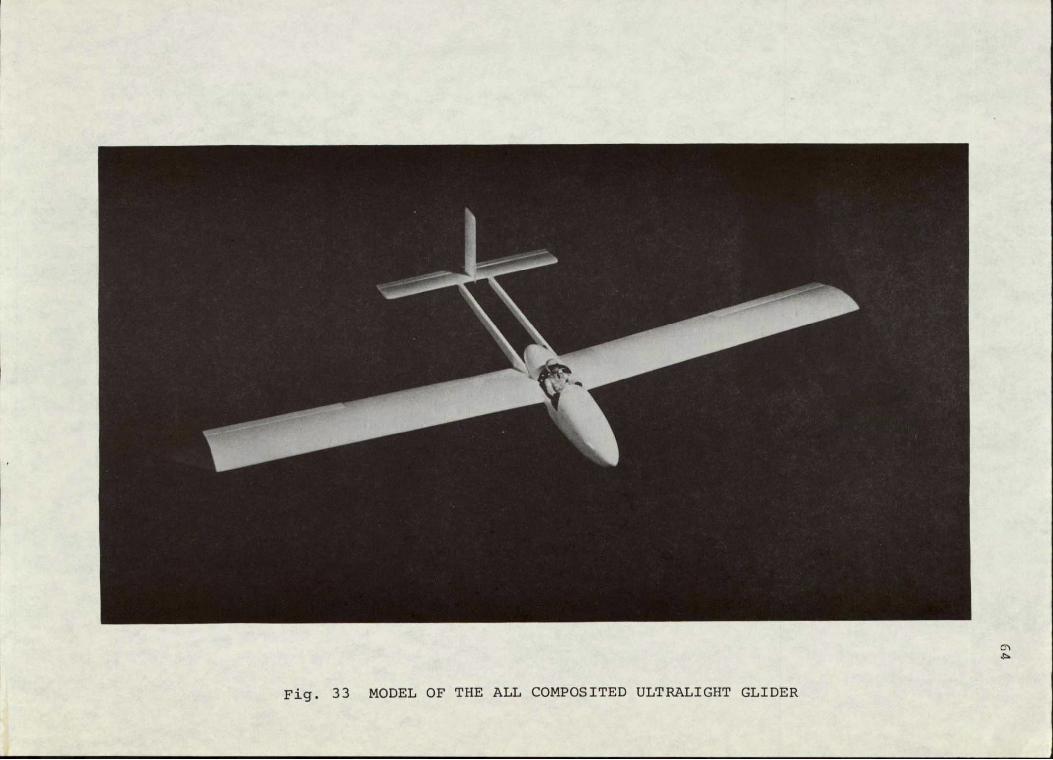
Fig. 33 MODEL OF THE ALL COMPOSITED ULTRALIGHT GLIDER
65
2. Fuselage Group - 6 students
A mock-up of the tail-boom and forward fuselage shell
has been fabricated in plywood and fiber glass, with the
final accommodation and structural protection for the re
clining pilot presently being assessed.
The fuselage shell fabrication technique has been work
ed out, the female mold has been constructed and two kevlar/
fiber glass half-shells have been fabricated. Figure 34 is
a photograph of the mock-up and forward fuselage shell.
3. Tail Group - 6 students
The prototype tail module for both the vertical and
horizontal tail surfaces has been fabricated, employing a
new technique of panel-on-ribs construction. In this process,
a single side, kevlar-stabilized foam sheet is laid up on a
flat surface. When the foam sheet is partially cured, it
is molded to the airfoil contour imposed by the foamed
plastic sheet ribs. A tail module rib assembly is shown in
Figure 35 and a completed surface in Figure 36. The skins
are kevlar, the leading edge is balsa.
This new technique produces an extremely lightweight
and true-to-tolerance airfoil shape, when the flight loads
are in the proper range, without the need for time-consuming
preparation of female molds. For the wing, the twisting
moment associated with the Wortmann FX 63-137 airfoil is too
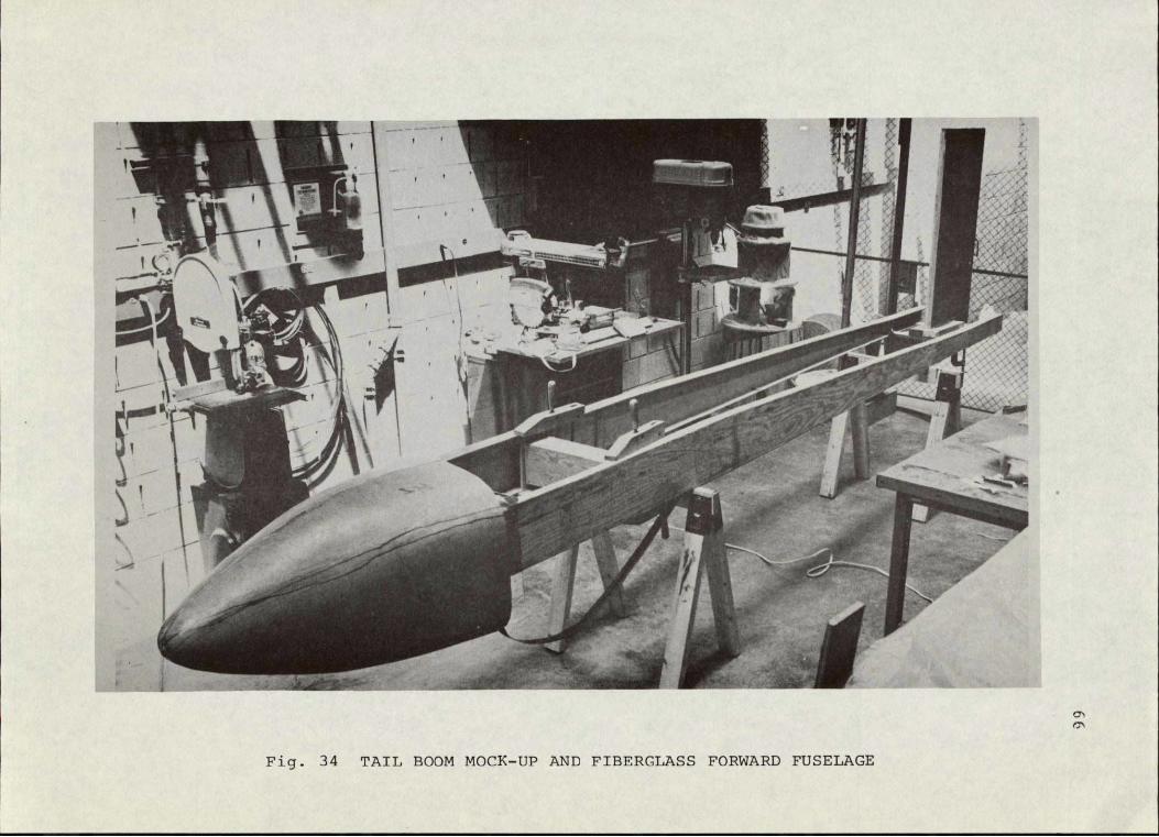
Fig. 34 TAIL BOOM MOCK-UP AND FIBERGLASS FORWARD FUSELAGE

S... ..... Fig. 35 TAIL MODULE RIB ASSEMBLY

63
Fig. 36 COMPLETED TAIL SURFACE
69
high for us to use this simplified construction method, but
the final method used on the wing is also an outgrowth of
the new technique described here. For future development of
ultra-light sailplanes, if low-pitching moment wing sections
are selected, the new technique can be used throughout and
represents an important breakthrough. Composite high-per
formance ultra-lights with air frame weights between 60 and
70 lbs. appear easily achievable by this construction tech
nique.
4. Controls Group - 6 students
Sample bell cranks and control horns have been produced
from symmetric carbon layups and have passed proof tests
under control forces according to FAA compliance suggestions.
Rudder and elevator hinge design alternatives have been ex
plored and fabricated. Their proof tests remain to be con
ducted. Control fixtures have been redesigned for the re
clined and/or upright pilot. These fixtures permit separate
elevator control but interconnected ailerons and rudder.
Sample control pushrods have been fabricated in the form of
3-foot length, 1-inch diameter carbon tubes. Attempts to
produce smaller diameter and greater length pushrods have
not yet been successful. In view of the fabrication sched
ule, however, standard general aviation control hardware
suitable for the prototype ultra-light sailplane has been
identified and ordered to provide a satisfactory though
slightly heavier back-up system.
70
5. Engine Group - 2 students
An air-cooled engine nominally rated at 9 hp was secured
to achieve the self-launch capability proposed as the second
demonstration project making use of a modification of the
current version of the aircraft. This engine is presently
undergoing tests, and the pusher propeller, drive train and
deployment mechanism are under study.
6. Aeroelastic Studies
An extensive set of calculations has been completed for
the new wing design which is currently being built. These
analyses verify that the static aeroelastic wing character
istics are satisfactory. For completeness (as well as the
student's edification), the distributions of lift, angle of
attack, elastic angle, torque, shear and bending moment were
calculated, assuming (in turn) a rigid wing, a semi-rigid
wing and a completely elastic wing. These calculations were
performed for the 30.5 m/s penetration condition.
The planform and the cross-sectional properties (of
interest) of the new wing are constant with span except for
a small tapered wing tip section. (See Figure 37 for both
planform and cross-sectional items of interest.) Therefore,
it was more convenient to deal analytically with the plan
for as a straight wing with a rigid weightless wing tip of
tapered planform. This method of formulation leads to an

71
GJ, ao CCONSTANT
,==o = WNG TIP C=1
WING PLAN FORM
.GCCmxC29
A.C. E.4 &C.G.
SNmg
C
"CONSTANT" WING CROSS-SECTION
Fig. 37 Schematic wing plan form and cross-section

72
unusual aeroelastic boundary value problem which is described
in the sequel in detail.
For conventional unswept subsonic wings, the offset
distance "e" between the aerodynamic center and the elastic
axis usually contributes much more of a twisting moment at
any generic wing section than does the couple customarily
called the aerofoil pitching moment. However, this is not
true for our glider wing since its pitching moment is an
order of magnitude larger than that of airfoil sections used
on conventional aircraft. Thus we will witness the unusual
phenomenon of aeroelastic effects unloading the outboard
portions of a straignt wing and moving the center of pressure
inboard. This in turn modifies the usual shapes of all the
above-mentioned distribution calculations.
A. The Basic Boundary Value Problem in Terms of the Elastic Wing
The basic problem is to determine, for a given load
factor N, the root angle of attack ar(0) and the elastic
twist angle distribution O(E) where measures the nondimen
sional length along the constant planform semi-span. Here
0 < F < 1 and E = 1 is the interface between the constant
planform semi-span and the root of the wing tip.
Given the rigid wing tip contributions to torque, moment
and lift per radian exerted on the boundary at = 1 (TI, M1
and LI, respectively), all distributions of interest may be
found from the elastic twist relation and its two boundary

73
conditions, subject to the constraint that the lift equals
the weight times the load factor (L = NW). These are given
by
d26 + (AR)2 =K* (Twist Eq.) 2
dE
e(0) =0
+ 81)] (Boundary Conditions)dO =()Tt U[(0)+r (]
1) NW = 2qcao0 [r(0) + e(E)]dE + 2L[ar(0) + e(1)] (L = NW Constraint Eq.)
0
where, referring to Figure 37 and in terms of usual aeronau
tical notation,
2 qcea0 GJ
a = ac /aa
2 rpV q =
K* = (0) + CmacC - mNgd)
The unusual feature of this problem is that the twist rate
boundary condition at =1 i.e. L(1) = .... depends on the
root angle ar (0) which is unknown until the L = Nq equation
(which contains ar(0) and 0( ) in integral form) is explicitly
solved for. As an additional complication, K* also depends on
r shown above.a(0) and N as

74
B. Elastic Wing Results
With much more labor than is characteristic of a usual
static aeroelastic problem we find
,.jw ng~dN c(d)+ F2 macF- /(F -FF2 ( e(0)Ie 2qCaoZ 2 a e 2 0 a-
OM = AsinZE + 2(1 - cosAZE)2(XZ)
where
K WN Wwing d r macc 2 -Z) 2qca0(0) ]e aleae
+ (T1 Z/GJ)c r(0)(X2 E- - cosXZ) (TIZ/GJ) - XksinhAI
A = LAcosxz - (T1/GJ)sinAZ]
O ao---sxF1 =1 + 1 Lcsins- (T Z/GJ) aca gjfZ A&t 2,jvzCOSx - (T 1 Z/.GJ) sinAj,
F2 sinXZ LI F=1- + C-o(1- coslt)
UZ qcaZ0
AsccsA TtG~i 1 cosXk lLLA-XsinAZ + (.1-COSU)(T1Z/GJ jAZ +
With the 0( ) distribution and ar(0) solved for a given N, we
find the lift distribution to be
qccz(E) = qcao[r(O) + 0()]
and we may write the torque, shear and moment distribution in
primitive form as
T(C) = (SJ/dto(GJZ)

75
I ±
S(C) = qcao J [ar(0) + 0(W)]dn - mgLN f dT + LlEr(0) + 0 (1)]
1J 1
MC(C) = at0k2 (n - C) (r) + (T)Idn 2Nf (n - E)dn
C C
+ [ar(0) + e(1)] [MI + XLI(1 - C)]
where n is a dummy variable of integration. Carrying out the
integrations and simplifying we find
T(C) = 2j-(Xt) LAcosx£ + sinXt
S( ) = [qca t ar(0) 7)2J - mgZNlC - )
+ aj - cos*t) os
Lr(0) + Asin + K ) (I(.
+ K - mg (i - 2 M(C) = ;2 [qca{ar(0)
qca0Z---[2 sinlt - sinUE (1 - C)XZcosXk}
-- cosUV - cosUiC + CI - C)?,ZsinX]
+ [L-(I-) + MI] r(0) + Asint - K* 2(1 cosX
r K*__
where a (0), 2' and A have been previously given,(for the (Xt)
elastic wing).
76
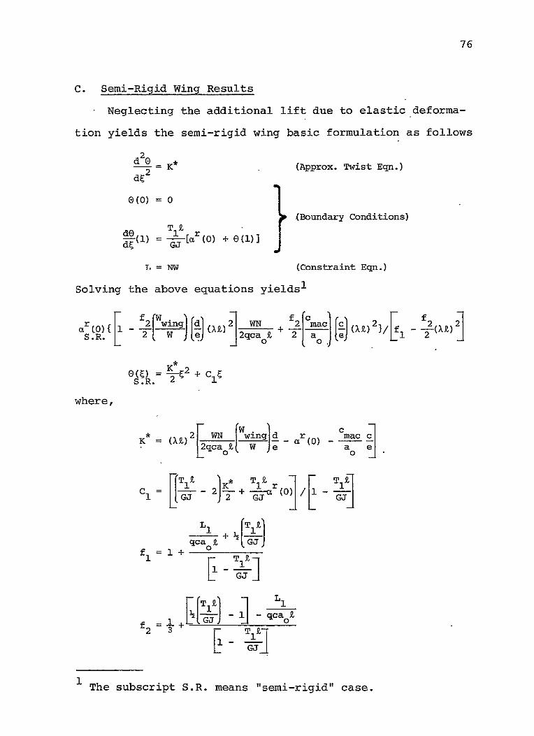
C. Semi-Rigid Wing Results
Neglecting the additional lift due to elastic deforma
tion yields the semi-rigid wing basic formulation as follows
d2 K (Approx. Twist Eqn.) d 2
0 (0) =01
(Boundary Conditions)
O(i) '=[ r(0) + 6(1)] GJ 4r
L = NW (Constraint Eqn.)
Solving the above equations yields1
r - [wing [dj (AZ) 22-N- + f[ c [c(XZ)2}/[i - (X2 2]
OM K* 2 + E S.R.C
where,
acK (X 2 W wing ar c m(0)
0
, af eC, K (j
cI = - T 1 (02
qca z + 3, 1 +I1
c-rqcf T ei)s b S] a i
The subscript S.R. means "semi-rigid" case.

77
and carrying out the torque, shear and moment distribution
expressions yields
T(E) = -[K* + C ] C1 K
S( ) = qca Z r(O) (1 - ) + C (i C2) 3
j20 aS.R"
r-K
0 ) e +mgZN(l - E) + L. lr( + 1 2-S.R.
M() = qcao 2 (1 - 4 (i(1 - ) C1 - - (I - C21C
+ 2 [qca cr(O) - mgN] (1 - E)2 0 S.R.
+ R( )L r(0) + C 1 + 2(1 1 S.R.
+Mlr(o) +c 1 +VJ ±[S.R.
whr S.R.1
section. Particularly note that the definition of K is
r(0), K* and C have been previously defined in this
different for the elastic case and the semi-rigid case.
D. Rigid Wing Results
By letting GJ- we obtain the (almost) trivial results
for the rigid wing. The rigid angle of attack atr 0 is rigid
immediately given by
ar (0) = NW/(2a S q)
R o T
where ST is the total area of the left (or right) wing, and
the torque, shear and moment distributions are given by

78
T(C) = [qcaeGl - C) + T1 ]aR(O) + Ic 2 - Nmgd](1- C)
S(Q) = [qca Z(1 - C)+ L ]r (0) - mgZN(1
r mg 2] i 2 r
M(C) = [qcao R(0) - (- + ILI£(I- ) + MI]aR(0)
where a (0) has just been previously defined.R
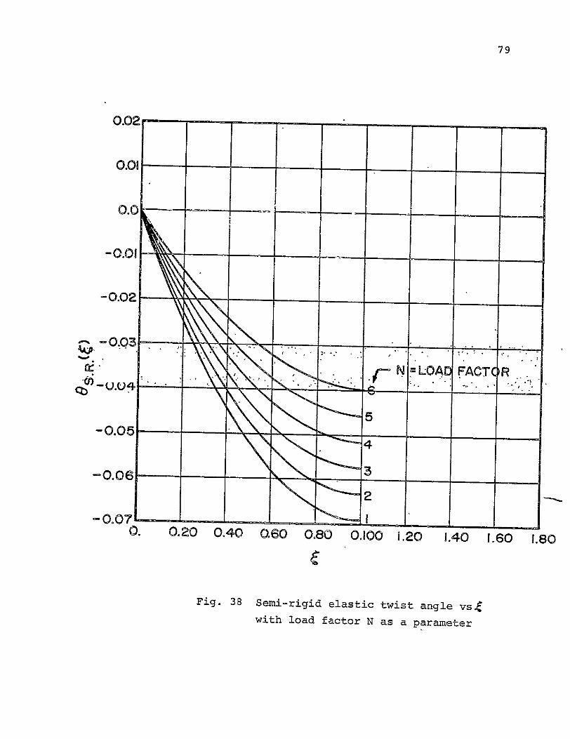
E. Numerical Results
Using the physical properties of the CAPGLIDE wing de
sign and the results of the previous sections, twist, total
angle, shear, bending increment and torque distribution with
span have been plotted in Figures 38 - 51 for various load
factors. Table VI presents the root angles of attack ver
sus load factor for the cases of rigid, semi-rigid and
elastic wings. Note that for N = 1, Table VI predicts that
the elastic wing root angle is 2.480 times larger than the
rigid root angle calculation; the semi-rigid to rigid root
angle ratio for N = 1 is shown to be 2.362.
TABLE VI
ROOT ANGLES OF ATTACK FOR RIGID [r ) SEMI-RIGID aro ANDCD)]R S.R.
-ELASTIC -WINGS .Er (0)1 VERSUS LOAD FACTOR
rr
N a (0. 5OS.a (0) 1 0.036096 0.08526 0.08952
2 0.072191 0.11703 0.12094
3 0.108288 0.14880 0.15236
4 0.144284 0.18057 0.18378
5 0.180480 0.21234 0.21520
6 0.216584 0.24411 0.24662

79
0.02
0.01
0.0
-0.01
-0.02 __
-0.03
NLOAD FACTOR
-o.oS -0.06
-0.07' 0.
-1
1__
0.20 0.40 060 0.80
C
2
1
0.100 1.20 _
1.40 _ _
1.60 1.80
Fig. 38 Semi-rigid elastic twist angle vs4
with load factor N as a parameter
79
0.02
0.01
0.0 .. .... .
-0.0I - ....
" . . .r~LOAD FACT R
-0.06
2
-0.0710. 0.20 0.40 0.60 0.80 0.100 .20 1.40 1.60 1.80
Fig. 38 Semi-rigid elastic twist angle vs4
with load factor N as a parameter

80
0.01
0.0
-0.01 -
-0.02
-0.03 -0.04 - " -A" R
cN =LOAD ACTO
-0.05- 5_
-0.06 _ _ _ _ _ _ _ _
-0.07
-0.08 0. 0.20 0.40' 0.60
(2
0.80 1,00 1.20 1.40 1,60 1.80
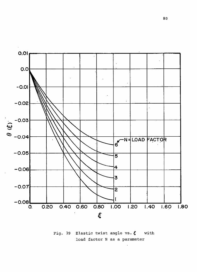
Fig. 39 Elastic twist angle vs. with
load factor N as a parameter
80
0.01
0.0
-0.01
- 0.02
-0.0 j-N LOAD FACTOR 6
-0.05
-0.06 4__
- 0.07
-0.081I 0. 0.20 0.40 0.60 0.80 1.00 1.20 1.40 1.60 1.80
Fig. 39 Elastic twist angle vs. with
load factor N as a parameter

81
0.36
0.32
0.28
0.24 "___
0.20,
f--jN
6I
LOAD FACTC R
0
0.06 5
0.08
0.4
0. 0.20 0.40 060 0.80 1.00 1.20 1.40 1.60 1.80
Fig. 40 Semi -rigid wind total angle vs.c
with load factor as a parameter
82
0.36
0.32
0.28
0.24 "-_ __ _ _
/-N N-LOADFFCTOR
+
0.12 "--' -4
101 0.
0. 0.20 0.40 0.60 0.80 1.00 1.20 1.40 1.60 1.80
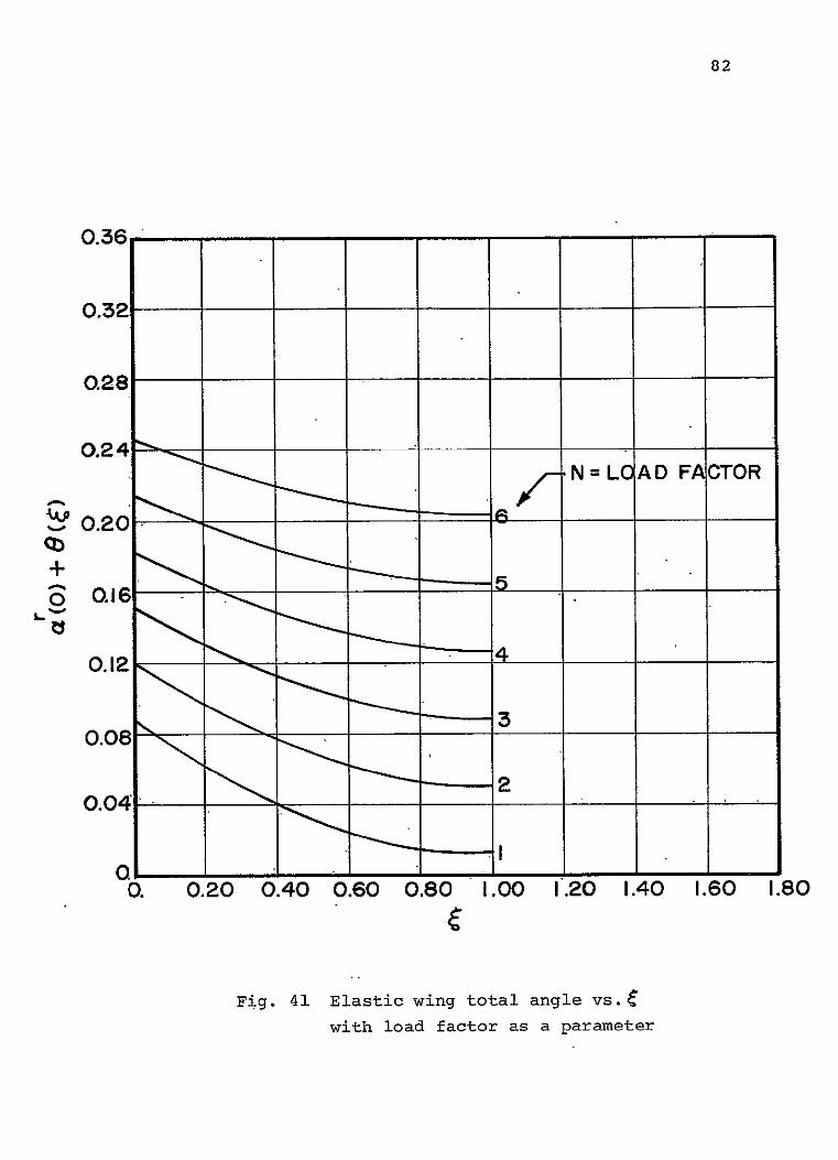
Fig. 41 Elastic wing total angle vs.c
with load factor as a parameter
83 0.24 - - ELASTIC
--- SEMI-RIGID 0.23- ---- RIGID
N=LOAD FACTOR0.22-
0.21t
0.20- K 0.19
0.18 - - - - - -
0.17
0.16 -.rl0.15 w4
0.14- 0 (a
o0.1-H r
S tp -- 4 r
+ 0.09 -o 0.08 04 C)
mt r4
rt 4J0.07 oca
0.06- .N1
0.05- 2 f 0 0
0.04- K I" 0.03W
0.02
00.1 0.2 0.3 0.4 0.5 0.8 -0.7 0.80.9 1.0
0.00

84
3600.0 0
-
3200.00
2800.00
2400.00
2000.00 5
- N=
I
OAD FACTOR
120 0.00 8600.00
3 .
400.00
0. 0.20 0.40 0.60 0.80 1.00 1.20 1.40 1.60 1.8C
Fig. 43 Rigid wind shear vs. C with
load factor N as a parameter

85
3600.00
3200.00
2800.00
2400.00
N LOAD FACTOIR
2000.00
C01600.00
800.00
400.00 "i'
OL 0. 0.20 0.40 0.60 0.80 1.00 1.20 1.40 1.60 1.80
Fig. 44 Semi-rigid wind shear vs.
with load factor N as a parameter

86
3600.00
3200.00
2800.00,
2400.00 \6
\ / N= OAD FIXCTOR
aooo.oo 1200.00
800.00,
400.00
0.1 0. 0.20 0.40 0.60 0.80
C 1.00 1.20 1.40 1.60 1.80
Fig. 45 Elastic wing shear vs. e with
load factor N as a parameter
9000.00
87
BO00.O0Q
7000.00 .N'= LOAD FACTOR
6000.00 6
5000.00
4K _ 4000.00
3000.00
2000.00 2
1000.00
0.20 0.40 0.60 0.80 [0 1.20 1.40 1.60 1.80
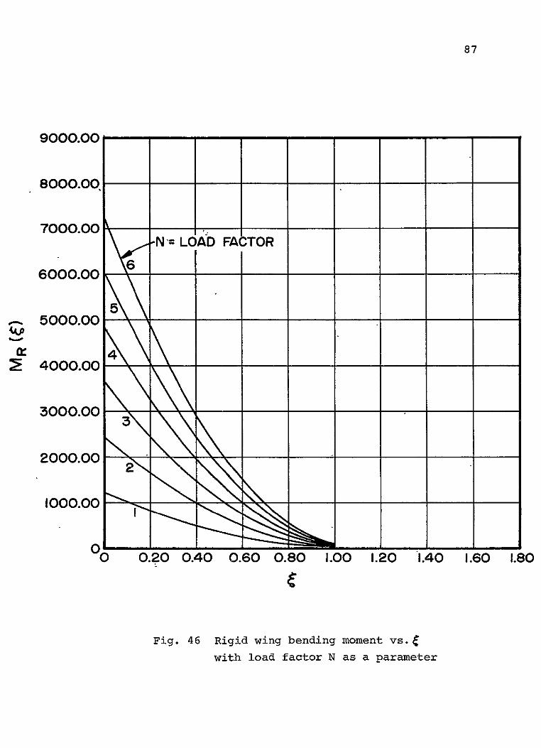
Fig. 46 Rigid wing bending moment vs.c
with load factor N as a parameter

88
7200.00 -
6400
5600.00 6
--N=LOAD FACTOR
4800P0
14000.00 44
3200.00
2400.00 \
1600.00 2
0. 0.20 0.40 0.60 0.80 1.00 1.20 1.40 1.60 1.80
Fig. 47 Semi-rigid wing bending moment vs.6
with load factor N as a parameter

89
7200.00
6400.00
- N =LOAD FACTOR
5600.00
4800.00
i4000.00
320.00
2400.00
1600.00
800.00
0 0 0.20 0.40 0.60 0.80 1.00 1.20 1.40 1.60 1.80
Fig. 48 Elastic wing bending moment vs.C
with load factor N as a parameter
90
80.00
0.
-80.00
-160.00
-240.00
r-320.00
-400.00 / /
-480.00
-560.00
- N =LOAD
-640.0011111111-64"00 0.20 0.40
FACTOR
0.60 0.80 1.00 1.20 1.40 1.60 1.80
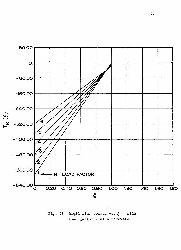
Fig. 49 Rigid wing torque vs. with
load factor N as a parameter

91
160.00
8000
0
-160.00
-240.00
-420.00
-400.00
____
0. 0.20 0.40 0.60 0.80 1.00 1.20 1.40 1.60 1.80
Fig. 50 Semi-rigid wing torque vs.
with load factor N as a parameter
80.00
2
0.
-160.00
-240.00
V- -320.00
-400.00
-480.00
S =LOAD FACTOR
-560.00
-640.00--------------------0 020 040 0.60 0.80 1.00 1.20 1.40 1.60 1.80
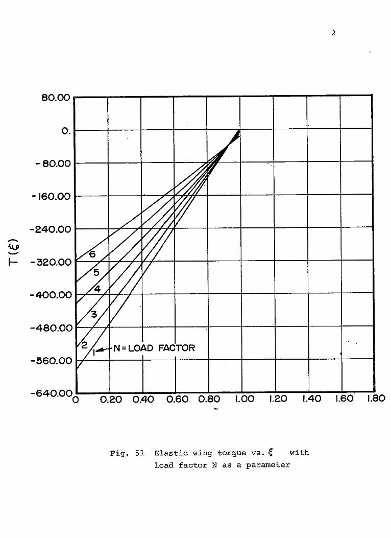
Fig. 51 Elastic wing torque vs. with
load factor N as a parameter

93
In Figures 38 and 39 it is noted-that allowing the wing
to become fully elastic causes larger negative twist distri
butions, and that for N = 1 the difference between %Alt and
0(1) is roughly one-half of a degree. Comparison of the
curves in Figures 40 and 41 shows that the outboard sections
of the fully elastic wing -are less loaded and that (hence)
the inboard sections carry more load when compared with the
semi-rigid wing. Obviously the center of pressure shifts
inboard when the fully elastic analysis is employed. The
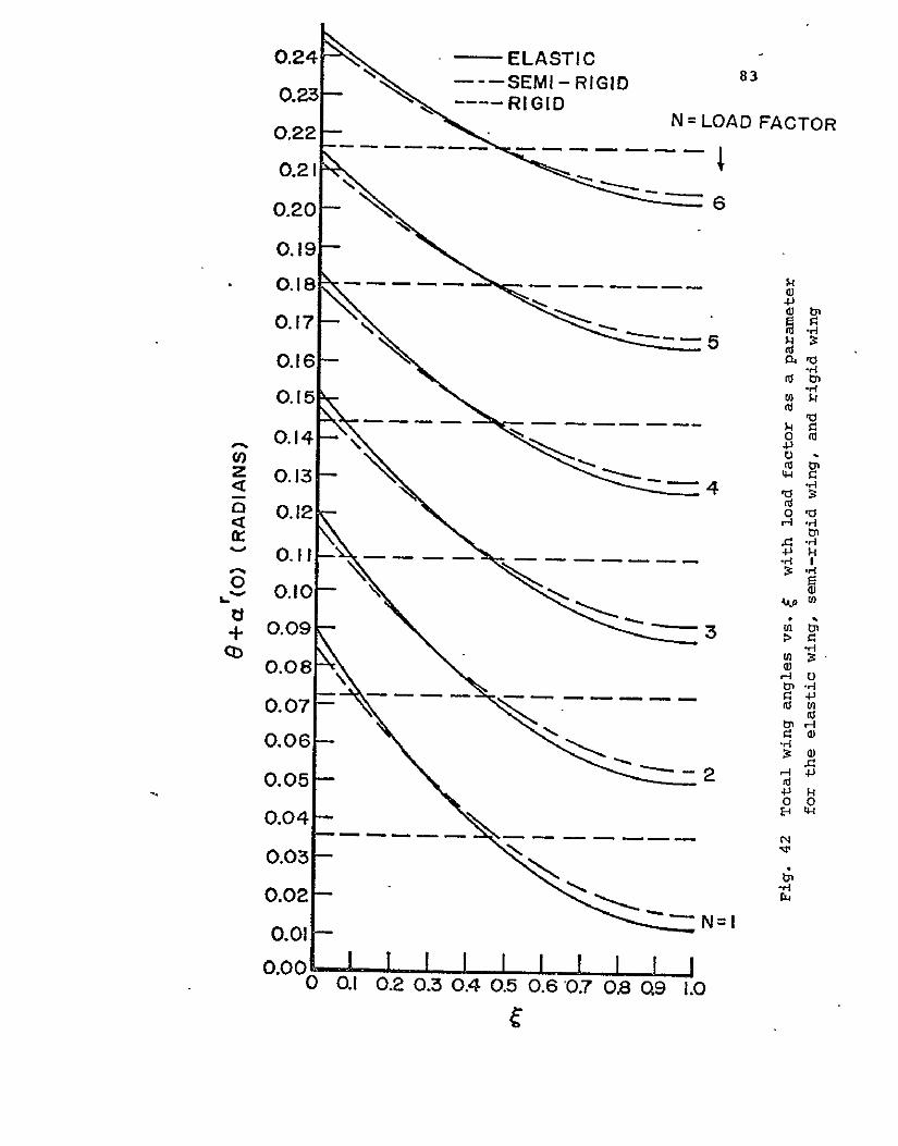
results of Figures 40 and 41, as well as the corresponding
rigid wing angles, are presented in Figure 42. The inboard
center of pressure shift is again reflected in the results
of the next two series of graphs (Figures 43, 44, 45 and
Figures 46, 47, 481 which plot the shear and bending moment
distributions for the rigid wing, the semi-rigid wing and
the fully elastic wing, respectively.
It is clear from reviewing the results of Figures 38
51 and Table VI that a rigid wing analysis gives very erro
neous values of all pertinent distribution quantities such
as shear, bending moment and torque and presents a very
large error in calculating the required root angle (roughly
three degrees at load factor N = 1). The distribution
quantities are important for their effect on structural in
tegrity and total weight, while the root angle of attack is
important because of its relation to the wing-fuselage
attachment angle which strongly influences all important

94
performance quantities (mainly through a non-minimum drag
configuration or a non-minimum configuration related to drag
and velocity). Further, because of a relatively small value
of At (i.e., a torsionally stiff wing and a modest A.C.-E.A.
offset distance "e") and a large value of (negative) cmac,
the differences between semi-rigid wing and fully elastic
wing distribution quantities is generally quite small (and
in fact the less rigorous semi-rigid analysis turns out to
be a conservative analysis). However, the small differences
in ar(0) and ar(0), as well as the distribution differences S.R.
in e(E1 and E(), should provide different estimates of per
formance capabilities.

95
PART III
COMPAD (Computer Aided Design)

96
COMPAD CComputer Aided Design)
(L. J. Feeserl
The computer aided design portion of the composites
project has continued in this reporting period, concentrating
for the most part in three separate activities: (a) main
tenance and continued enhancement of the finite element com
puter program r SPAR, Cbl initial review of structural optimi
zation programs and Cc) preliminary study of the feasibility
of the use of array processor technology for improving the
speed performance of the program SPAR on our Prime computers.
Considerable effort has been expended on maintaining a
working version of SPAR on the Prime computers. Most of this
work has been necessary because of updating in the Prime
operating system, In addition, a number of students and
faculty have obtained hands-on experience in preparing finite
element models and coding their input for runs using SPAR.
This experience has demonstrated the continued need to keep
in close contact with NASA Langley personnel in regard to
continued enhancements of SPAR.
The whole area of pre- and post-processing for finite
element analysis is moving ahead under the direction of Pro
fessor Mark Shephard. Students in his finite element class
have been developing individual pieces of a pre-processing
system which will be assembled into a trial system during
the next six months.

97
The project has also obtained the documentation of the
program ACCESS, a structural optimization program developed
by Dr. Lucian Schmidt, under NASA contract. We are evaluat
ing the potential of this program for implementation on our
computer systems and for its potential use in structural de
sign related to the composites project.
A preliminary feasibility study has been performed on
the potential use of the Floating Point Systems AP120 array
processor for speeding up of some of the compute-bound code
in SPAR. This preliminary work shows a strong potential for
improved speeds. However, the limited study to date has
used only the timings from the actual execution of some of
the array processor operations and has neglected the trans
fer times involved in interdevice communications. We have
also used only small pieces of code lifted from a number of
routines and have not simulated a total SPAR run. The im
provements possible in this area are great. We plan to con
tinue these developments as having considerable potential.
98
PART IV
SUPPORTING RESEARCH
Progress on composites research is reported in the indi
vidual write-ups on the succeeding pages in the following
areas:
Resin Characterization and Optimization
Moisture Effects on Composite Structural Materials
Optimization of Laminated Plate Design for Shear
Ultrasonic Non-Destructive Testing Developments
Fatigue in Composite Materials
Metal Matrix Composites
The report on Metal Matrix Composites is a final one under
this project. While results of interest and high quality
are being obtained, they are deemed less appropriate than
other investigations as part of the NASA/AFOSR Composite
Materials and Structures Research Program at Rensselaer.
Accordingly, this work has been concluded under the subject
grant.

99
RESIN CHARACTERIZATION AND OPTIMIZATION
Senior Investigators: G. Diefendorf C. LeMaistre
A serious problem in the fabrication of composites is
the batch-to-batch variation in the properties of resins
used as matrix materials. Ideally, provided a particular
cure cycle is followed, the cured resin should-have repro
ducible properties. Problems in this regard have been met
in the CAPGLIDE program, where difficulties have been ex
perienced with the resin systems. The possibility of in
correct mixing and/or curing has been considered, but the
problem has persisted despite close supervision and atten
tion to detail. An examination of the chemistry and related
physical properties of commercially available resins has
been carried out to see if the present problems can be
eliminated.
An additional intent of this investigation is to select
an epoxy resin system that produces the optimum composite
properties when used as a matrix with carbon fibers. The
current wet lay-up practice of using the same epoxy system
for glass and carbon fiber reinforcements, while convenient,
may not be the best. Investigations of both room tempera
ture and high temperature curing resins have begun.
The resin systems investigated include:
1. Resin Ciba Geigy (Araldite 508 and 509)
Hardeners XU 224 - Developmental hardener: long pot life (active hydrogen equivalent 143)
Cure - Room tenperature

100
2. Resin - Epon 828
Hardener - Nadi methyl anhydride
Catalyst - MPDA
Cure - Up to 1500C
Several analytical methods are being used to charac
terize the resins in their cured and uncured conditions.
A. High performance liquid chromatography (HPLC):
Samples of the resins, hardeners and cata
lysts have been dissolved in tetrahydrofuran
(THF) and subjected to HPLC, the initial
intention being-to obtain a "finger-print"
of the currently available resin systems
and to use this for comparison with in
coming batches of the same resin system.
In addition, the mixed but uncured resins
have been dissolved in THF and studied
with the HPLC as have the cured and semicured resins. Initial results have been
obtained, and this work is continuing.
B. Infra-red spectroscopy:
This is under investigation as a tool
for determining the species in a resin
and the progress of the cure-cycle.
C. Differential scanning calorimeter:
Epoxy resins during their cure cycle
go through an exothermic reaction.
The extent of the cure and the effect
of additives, etc. can be deduced by
noting the occurrence and extent of the
exotherm in the "cured" samples. In
the case of the Epon 828 system, the

101
exotherm occurs at approximately 230'C
for poorly cured resins. No exotherm
is noted for a fully cured resin system.
D. Shear strength:
The shear strength of the "character
ized" resins is also under study. In
the case of the cured resin without
fiber reinforcing, the assembly recom
mended in ASTM 372 has been fabricated.
The cured resin sheet is tested in shear
by means of a punch and die assembly.
Fiber reinforced systems will be tested
by the "short beam" shear test.
As stated in the previous report, the Araldite 509,
xu 224 and XU 225 system has an advantage in that, by vary
ing the ratios of XU 224 and XU 225, the gel and pot life
of the resin system can be altered. The manufacturer's
recommended use of XU 224 and XU 225 to alter gel and pot
life is given in Table VII.
TABLE VII POT LIFE A14D GEL TIMES FOR RESIN SYSTEM
Resin (PBW)a Hardener (PBW) Pot Gel Batch A 509 XU 224 XU 225 (hr) (hr)
1 100 27 30 0.5 0.75
2 100 29 23 1.0 1.25
3 100 34 15 1.5 2.50
4 100 34 9 2.5 3.50
5 100 42 0 3.5 6.00
a (PBW) parts by water

102
The ratio of hardener to resin is calculated on the
basis of active hydrogen equivalent. However, there is a
variation in the mw of the A 509 (WPE = 189-200) and in the
active hydrogen equivalent of XU 224 (AHE = 70-75). The
manufacturer's calculations are based on the lowest mw of
A 509 (i.e. 189) and highest AHE of XU 224 (i.e. 75) and
are thus likely to err on the side of excess hardener addi
tions. These systems are now being analyzed to determine
if excess hardener is truly present and if it is the cause
of poor cures. The physical properties of the resulting
materials are being measured to determine variations whether
or not excess hardener is present.

103
MOISTURE EFFECTS ON COMPOSITE STRUCTURAL MATERIALS
Senior Investigator: S. S. Sternstein
Theoretical studies on the effects of moisture on the
physical properties of ,epoxy resins containing cylindrical
fibers have shown that inhomogeneous swelling phenomena may
be extremely important in determining internal stresses and
strains and moisture gradients. These internal gradients
may lead to sufficiently high local stresses as to cause
failure of the matrix (precracking). Consideration is pres
ently being given to the problem of defining local instabil
ity criteria vis-a-vis our inhomogeneous swelling theory.
It appears that there may be critical values of cohesive
energy density or crosslink density of the matrix which pre
clude equilibrium swelling fields from being established.
Under'such a condition the matrix would literally disinte
grate by profuse cracking and chain scission. Such "unzip
ping" has been known to occur on occasion.
Experimental studies are in progress on the viscoelastic
characterization of wet and dry epoxyresins. The purpose
here is twofold. First, it is essential to obtain certain
data which are needed in the inhomogeneous swelling theory.
Second, we intend to obtain a comprehensive and reliable
viscoelastic profile of epoxy resins. Several techniques
are being utilized, including dynamic mechanical spectros
copy, creep, stress relaxation and thermomechanical analysis.

104
Temperature'ranges from -1500C to 2500C and frequency ranges
from 0.1 Hz to 100 Hz are being investigated using several
sample geometries and modes of loading, e.g., tension,ocom
pression and shear.

105
OPTIMIZATION OF LAMINATED PLATE DESIGN FOR SHEAR *
Senior Investigator: Y. Hirano
The objective of this program was to apply a mathema
tical optimization technique (Powell's method) to find the
fiber directions in each layer of a laminated plate that
give the highest shear buckling stress. The plates con
sidered are laminates of N orthotropic layers whose princi
pal material axes coincide with the plate axes. Each layer
is assumed to have the same thickness and an equal number
of fibers in the direction of +ai and -ai with respect to
the plate axes (x-axes).
Shear buckling stresses of the plates were calculated
by utilizing Galerkin's method. A-computer code, developed
by Powell, was rearranged into the code written for the cal
culation of shear buckling stress. The numerical calcula
tions were made for boron/epoxy plates with length to width
ratios, or "aspect ratio", R = a/b = 1, 1.5 and 3. The cal
culation was first carried out for three-layered plates with
a/b = 1. An example of the numerical convergence for this
case is shown in Figure 52. In this figure T is defined as
7r/(32Nxyb2R3 ), where Nxy is shearing force per unit width,
b is the width of the plates and R is the aspect ratio of
the plates. Next, the calculation was made for the case of
A note related to this work has been accepted for publication in the AIAA Journal.

106
1.4
1L0 2
1.3
7/4 1.2
0.5 1.1
1.0
- - = =0.9 0 I 2 3 4 5
No. of iterations
Fig. 52 Variation of a. and 4 with number of iterations

107
six-layered plates with a/b = 1, 1.5 and 3. The numerical
results for the case a/b = 1.5 are shown in Table VIII.
Asterisks in this table indicate that the numerical calcu
lations were stopped because maximum changes in the single
variable search did not alter the objective function values.
From Table VIII and from the results for the cases R = 1
and 3, the following conclusions were drawn:
1) An angle-ply laminate gives the highest shear buckling stress with the optimum fiber direction varying with the length to width ratio.
2) The method appears to converge to the optimum with virtually any choice of initial fiber direction.
3) The best fiber directions for the cases R = 1, 1.5 and 3 are ±450, ±550 and ±600 respectively.
Shear buckling stresses of angle-ply laminated plates
with various aspect ratios were calculated, and the results
are shown in Figure 53. From this figure we can find the
best fiber directions of laminated plates under shear, for
aspect ratios from 1.0 to 5.0.

108
k
40
a/b=lI
30
20 2
I0
I I I I I I I I I 0 I00 200 30 ° 400 500 600 700 800 900
a
Fig. 53 Shear buckling force of angle-ply laminated plates
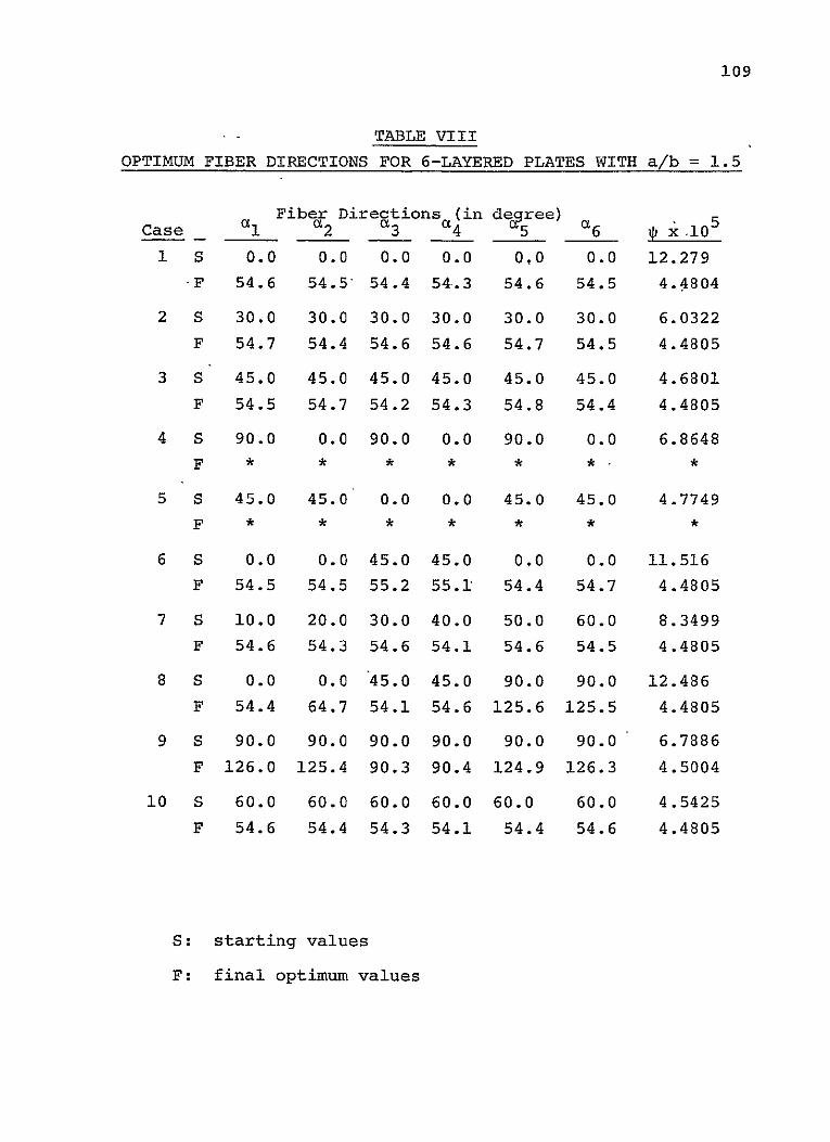
109
S- TABLE VIII
OPTIMUM FIBER DIRECTIONS FOR 6-LAYERED PLATES WITH a/b = 1.5
Fiber Directions (in de Case 1i _2 3 4 5 _6 1 x i05 1 S 0.0 0.0 0.0 0.0 0.0 0.0 12.279
.F 54.6 54.5' 54.4 54-.3 54.6 54.5 4.4804
2 S 30.0 30.0 30.0 30.0 30.0 30.0 6.0322
F 54.7 54.4 54.6 54.6 54.7 54.5 4.4805
3 S 45.0 45.0 45.0 45.0 45.0 45.0 4.6801
F 54.5 54.7 54.2 54.3 54.8 54.4 4.4805
4 S 90.0 0.0 90.0 0.0 90.0 0.0 6.8648
5 S 45.0 45.0 0.0 0.0 45.0 45.0 4.7749 F * * * * * * *
6 S 0.0 0.0 45.0 45.0 0.0 0.0 11.516
F 54.5 54.5 55.2 55.1 54.4 54.7 4.4805
7 S 10.0 20.0 30.0 40.0 50.0 60.0 8.3499
F 54.6 54.3 54.6 54.1 54.6 54.5 4.4805
8 S 0.0 0.0 45.0 45.0 90.0 90.0 12.486
F 54.4 64.7 54.1 54.6 125.6 125.5 4.4805
9 S 90.0 90.0 90.0 90.0 90.0 90.0 6.7986
F 126.0 125.4 90.3 90.4 124.9 126.3 4.5004
10 S 60.0 60.0 60.0 60.0 60.0 60.0 4.5425
F 54.6 54.4 54.3 54.1 54.4 54.6 4.4805
S: starting values
F: final optimum values

110
ULTRASONIC NON-DESTRUCTIVE TESTING DEVELOPMENTS
Senior Investigators: H. F. Tiersten P. K. Das
Since the last report was submitted considerable experi
mental work has been done in measuring the influence of a
tuning inductor on the bandwidth and sensitivity of the
trapped energy mode transducer. The inductances employed
have been systematically increased to relatively large values,
and 3 db bandwidths of the order of 20% of the center fre
quency have been measured. The inductances have served not
only to increase the bandwidth but to increase the sensitiv
ity as well, In fact, in an experiment in which the trapped
energy modes are reflected from the surface of the water at
normal incidence and detected by the transducer, the ratio
of the detected to the applied voltage is less than 20 db.
In the experiments on the monolithic mosaic transducer
that have been performed to date, a certain very interesting,
hitherto unreported and presently not fully explained phenom
enon has been observed. As the frequency is decreased below
the point at which ordinary trapping disappears, a very
sensitive trapped mode occurs over a very narrow frequency
band and then disappears as the frequency is lowered further.
With a further decrease in driving frequency a somewhat less
sensitive trapped mode occurs, which has a large bandwidth
and disappears at a very low frequency. In all cases the
existence of energy trapping has been verified by measuring

the mode shape by means of the acousto-optic diffraction of
a laser beam. Although at most frequencies the trapped mode
shape has a single maximum at the center of the electrode,
at certain frequencies the trapped mode exhibits a more com
plicated shape with two maxima across the electrode and a
local minimum at the center.
The computer interfacing for obtaining images from raw
transducer data has been significantly improved, and con
siderably better images are now being obtained. The instru
mentation for the excitation and detection of the fundamental
extensional and flexural plate waves tsurface waves). has been
improved.
The analysis of the thickness-extensional trapped energy
mode transducer with strip electrodes, in which only the one
dominant wave in each region is retained, has been extended
to include the coupling with certain other waves that exhibit
dispersion curves near that of the dominant wave. The fre
quency spectrum obtained from the extended analysis is more
complicated than the previous one in that a splitting appears,
which is caused by the coupling of two independent sets of
solutions. When the driving frequency is such that the two
split modes exist in a strong coupling region, the aforemen
tioned unusual mode shape with two maxima across the elec
trodes exists. Under other circumstances the usual mode
shape with one maximum at the center exists. Work has been
started on determining the lowest complex dispersion curves

112
for the symmetric extensional waves in an infinite PZT-7A
plate for both the unelectroded case and that of the shorted
electrodes, which are needed for the explanation of the
aforementioned observed behavior of the trapped energy modes
in the lower frequency range.

113
FATIGUE IN COMPOSITE STRUCTURES-
Senior Investigator: E. Krempl
Two different uniaxial fatigue test specimen designs
were evaluated. A straight sided specimen with thin tabs
was shown to be superior to a dog-bone shaped specimen.
Static and fatigue tests were performed on unidirectional,
cross-ply and quasi-isotropic graphite-epoxy laminates. For
the quasi-isotropic laminates, a significant effect of R
ratio*and a significant effect of frequency was observed.
All laminates were made at RPI from HY-E1030 (T300-934)
graphite epoxy, manufactured by Fiberite Corporation, using
the cure cycle recommended by the manufacturer. Each lami
nate consisted of twelve graphite plies; unidirectional,
cross-ply and quasi-isotropic laminates were made. The
stress-strain diagrams of these laminates are shown in Fig
ure 54. The reduction in stiffness and strength with an in
crease of the number of non-zero degree plies is obvious.
For fatigue testing we considered a dog-bone type and
a straight-sided type specimen, as shown in Figure 55.
According to ASTM D3039-76, straight-sided specimens show a
greater number of failures in the gauge length than the dog
bone type specimens. Accordingly the straight-sided speci
mens were used for the fatigue studies.
Fatigue tests were performed on symmetric laminates
10/(±45) 2/9O and [90/(*45)/0] S. Figure 56 shows that the
* The ratio of alternating to steady stress level.

Stre
ss,
MPa
.o
0 o o
o
w
w
0 °J
r
H
P,
0 H
-0
U)
U1
10
Fl.
S0
I0
o
o Fjres
KS
I-ft0
(D
-
H
H.
tS
H
p
, (t
0
Stre
ss
KSIH
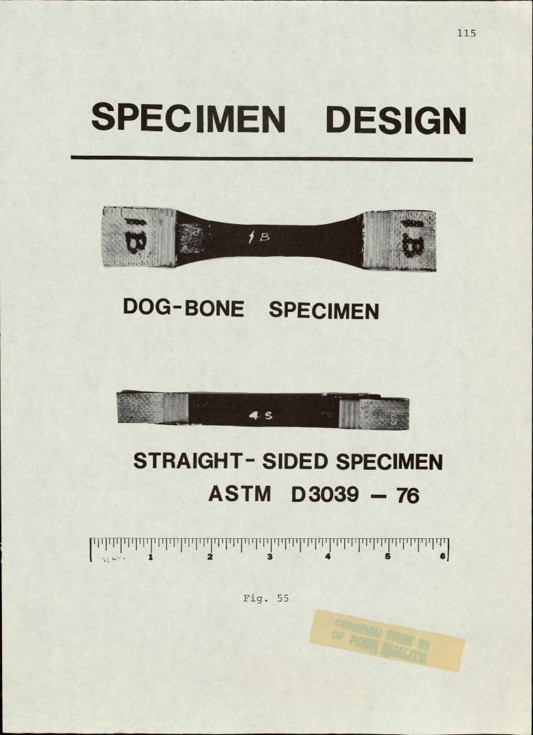
115
SPECIMEN DESIGN
DOG-BONE SPECIMEN
STRAIGHT- SIDED SPECIMEN ASTM D3039 - 76
l1'P1Tffr lll'F'llWI~ 'Il'Pl lllF I h PlqTTl WI IThT1 2 4 T T P' elJ
Fig. 55
I

0
a /r r9o,;45isyo
MOMi : tpMte Epay
FfW~mEJ: 600 cp
Rrat . -- 20
Log N
Fig. 56
117
[0/(±45)2/90 S has a better fatigue performance than the
[90/(T45)2/01S laminate for an R-ratio of -0.20. This R
ratio could be obtained without buckling of the specimens.
Photographs of failed specimens are given in Figure 57.
The failures in the gauge section are very well visible.
The test results, shown in Figure 58, indicate that frequency
has a considerable effect on the fatigue life of [90/(:45)20] S
laminates. We find this an effect of considerable signifi
cance. Other fatigue tests using approximate R-ratios of
.66 produced results with considerable scatter. We also
measured the stress-strain diagram of specimens made of
90/(:45)20]S laminates which we subjected to fatigue cyc
ling but not tested to failure. The stress-strain diagrams
of these cycled specimens were different from those obtained
on virgin specimens of the same laminates.
We will continue fatigue testing to further explore the
effects of R-ratio and frequency on composite structural
materials.
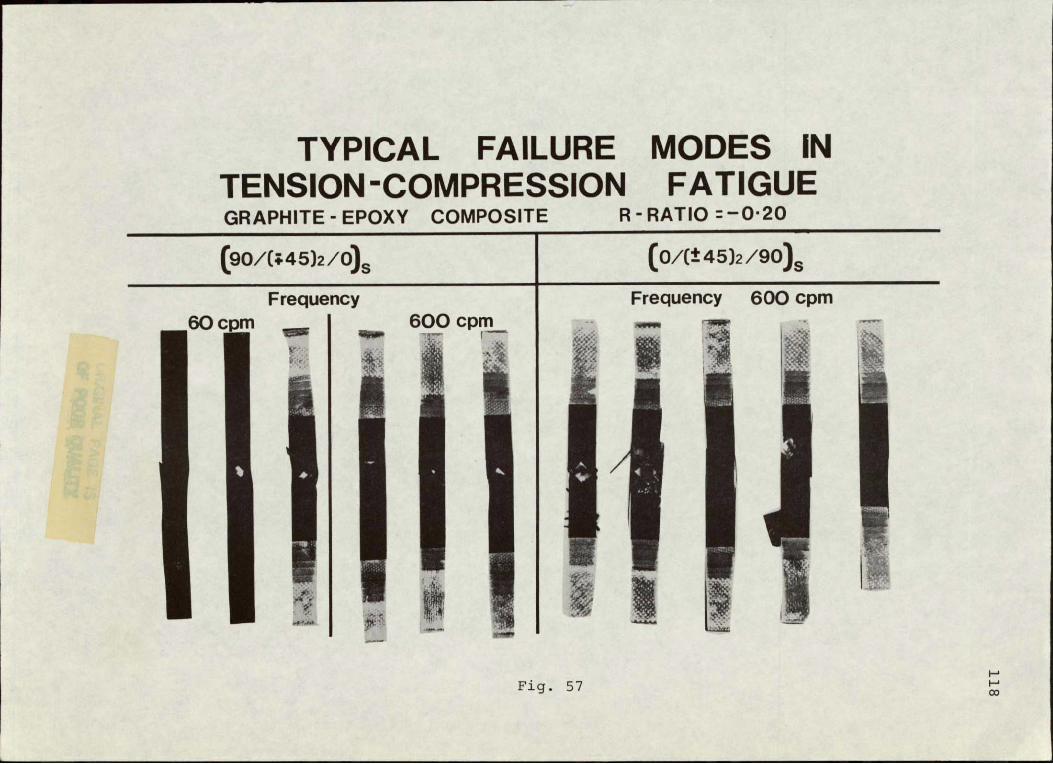
TYPICAL FAILURE MODES IN TENSION -COMPRESSION FATIGUE GRAPHITE - EPOXY COMPOSITE R- RATIO =--20
(9O/(;m45)2/O)S (0/ct145)2 /9O).
Frequency Frequency 600 cpm 600 cpm
60cm
57 Fig.

070 °[9/ (;45)2!./
'a/l60°C.60
CP
ORMI /60
0.50 Material : Graphite Epoxy
R ratio -020
,102 , 10 10
Log N
Fig. 58
120
METAL MATRIX COMPOSITES
Senior Investigator: N. S. Stoloff
The objective of this program has been to determine
those microstructural factors that control the mechanical
behavior of advanced metal matrix composites. Since the
directionally solidified Ni-Al-Mo eutectic system has good
tensile,-creep and fatigue properties, it was chosen for
study. Mechanical tests have been performed on AG-15 (Ni,
17.7a%Al,16.3a%Mo) and AG-34 (Ni,14.4%Al,20.0%Mo) in the
aligned condition.
The room temperature fatigue lives of both alloys were
superior in vacuum to properties in air. In testing done
at a frequency of 20 hz and a constant minimum stress of 5
ksi, the 107 endurance limit of AG-34 was increased from a
peak stress of 120 ksi in air, to a peak stress of 140 ksi
in vacuum. At 140 ksi the improvement in life was three
fold, whereas, at 160 ksi, the increase was less dramatic
(2.5 timesl. AG-15 showed a ten fold improvement in life
for vacuum tests at peak stresses of 130 and 110 ksi.
As reported earlier, fatigue crack initiation occurs
at the surface in testing done at room temperature, while
initiation at the center of the specimen was evident at
825°C. This indicates that creep plays a significant role
in fatigue at 8251C. Additional tests conducted at 7250C
have shown that creep processes are minimized at high fre
quencies. Following a trend established earlier with

121
tensile properties, the fatigue strength of AG-15 is highest
at intermediate temperatures. The life at 110 ksi is fifty
times greater at 725 0C than at 825°C; it is also six times
greater than the life at 250C. Frequency variations at
7250C in S-N and crack propagation tests will be used to
further characterize the creep-fatigue interaction in AG-15.
Initial transmission electron microscopy (TEM) studies
on as-DS AG-15 and AG-34 show a predominantly y' (Ni3Al)
matrix with a (Mo) fibers. AG-15 shows less residual y (Ni
rich solid solution) due to its higher Al content. Solu
tion-treated and aged specimens of AG-34 show a distribution
of fine (0.2pm) y' in the y matrix. The as-DS substructure
-exhibits planar arrays of dislocations in the y' matrix and
looped dislocations in the bcc Mo fiber.
Additional hydrogen embrittlement studies have been
carried out on AG-15 and AG-34. Molybdenum fibers, which
undergo ductile fracture in unchanged specimens, reveal many
brittle-appearing cracks after simultaneous charging and
tensile testing. Embrittlement of the fibers by hydrogen
seems to be the major cause of embrittlement of the composite.

122
PART V
PERSONNEL
AUTHOR INDEX

123
PERSONNEL
Senior Investigators
Brunelle, E. J., Jr., Sc.D. Associate Professor of (Aeroelastic and structures Aeronautical Engineering design and analysis, CAP-GLIDE)*
Das, P. K., Ph.D. Professor of Electrical and (Non-destructive evalua- Systems Engineering tion, research)*
Diefendorf, R. J., Ph.D. Professor of Materials (Fabrication, CAPGLIDE; Engineering fiber behavior, research)*
Feeser, L. J., Ph.D. Professor of Civil Engineering (Computer applications and graphics, computer aided design, optimization)*
Hagerup, H. J., Ph.D. Associate Professor of (Aerodynamics, configura- Aeronautical Engineering tion, pilot accommodation, CAPGLIDE)*
Helwig, G., Dr.Ing. Research Assistant Professor (Finite element methods, of Aeronautical Engineering computer aided design, composite structure optimization, CAPGLIDE)*
Hirano, Y., Ph.D. Visiting Professor of (Structures, composite Aeronautical and Mechanical buckling)* Engineering
Hoff, N. J., Ph.D. John A. Clark and Edward T. (Structural design and Crossan Professor of Engineeranalysis, CAPGLIDE)* ing
Krempl, E., Dr.Ing. Professor of Mechanics and (Fatigue studies, Director of Cyclic Strain research)* Laboratory
Sternstein,.S. S., Ph.D. William Weightman Walker (Failure analysis, matrix Professor of Polymer behavior, research)* Engineering
Fields of Speciality

124
Stoloff, N. S., Ph.D. Professor of Materials (Directionally solidified Engineering eutectics, research)*
Tiersten, H. F., Ph.D. Professor of Mechanics (Non-destructive evaluation theory, research)*
Research Staff
Research Associates
Kenmochi, Kiyoshi, Ph.D. Sinha, Bikash K., Ph.D.
LeMaistre, Christopher, Ph.D.
Graduate Assistants
Altman, Carl, B.A. Muser, Cristoph, Dipl.Mech.Ing.
Berg, R. William, B.S. Rosenthal, Jay, B.S.
Chan, Ka-Tung, B.S. Seagroves, William, B.A.
Chen, Lien-Wen, M.S. Shick, D.V., B.S.
Ely, Dale R., B.A. Sundaram, Viswanath, M.S.
Fisher, Mark Thomas, B.S. Talley, S., B.S.
Hoskote, Mangesh, B.E. Tartaglia, John M., B.S.
Kim, Wonsub, B.S. Teferra, Michael, M.S.
Klein, Leigh, B.S.. Van Shoonveld, H. Garrit, B.S.
Meyer, Bruce, M.S. Yang, Phillip, B.S.
Undergraduate Assistants - Seniors
Donnelly, J. Patrick Shoales, Gregory A.
Ezzo, Jeffrey Speicher, Terrance L.
Lenyo, John S. Weisenger, Norman
Melnyk, Michael S. Venner, Joseph
Reusch, David Rogers, R. George
Shaefer, Paul
FFields of Speciality

125
Undergraduate Assistants - Juniors
Borfitz, Michael Marchisotto, Paul
Chast, George Riker, Steven
Coy, Paul F. Schriber, Steven
Dearborn, John Schwitter, William
Emmel, John Snyder, Scott
Fallon, William Tavares, Mario
Flint, Fred Van Etten, Charles
Fortune, James Wetzel, Eric
Gorley, Ronald Witte, Mark
Grandon, Albert
Kearns, Thomas

126
AUTHOR INDEX
Page
Brunelle, E. J., Jr .................................. 59
Das, P. K ............................................ 59,110
Diefendorf, R. J ...................................... 99
Feeser, L. J .......................................... 96
Hagerup, H. J ........................................ 59
Helwig, G............................................ 59
Hirano, Y............................................ 14,105
Hoff, N. J ........................................... 14,59
Kenmochi, K.......................................... 14
Krempl, E.. .......................................... 116
LeMaistre, C......................................... 59,99
Sternstein, S. S ..................................... 103
Stoloff, N. S ........................................ 120
Tiersten, H. F ....................................... 110
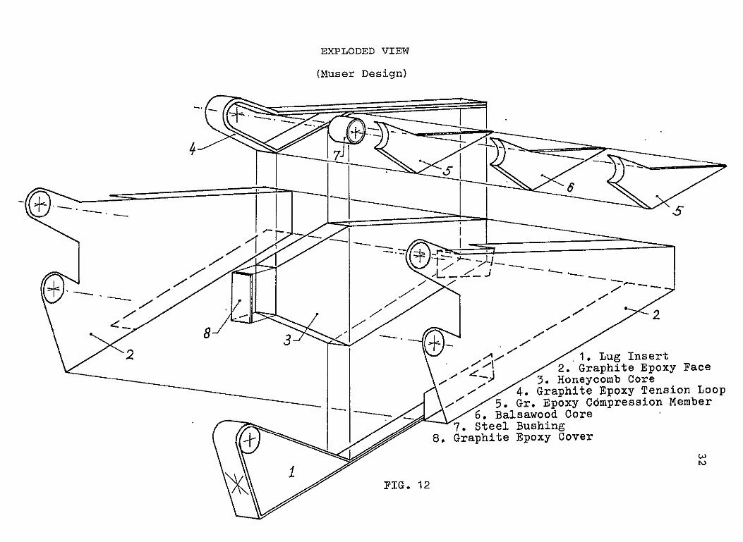
EXPLODED VIEW
(Muser Design)
4 -I
l4 -. q
At/ 2 . Lug Insert 2. Graphite Epoxy Face
3. Honeycomb Core 4. Graphite Epoxy Tension Loop
6. Balsawood Core5. Gr. Epoxy Compression Member I 7. Steel Bushing
S. Graphite Epoxy Cover
PIG. 12

0.24 E,LASTIC 83--- SEMI-RIGID_
0.23 --0"N RIGID =LOAD FACTOR
0.22 - - - - -
0.21
0.19
4-)40.18 - - -- - - -
0.17 5 0.16- iai o
0.15d
-d
0.14-) -P
4
Z 0.12 0:
41 .,4
-0.D 0.11- \\ Irk
<it 0 )0.09- i I
rqo
O;z s- 0.10 -
0.05 -
0.01 (
0~~~~~~~~~ 0.0203o405. zoso9
0 01 02 03 04 0 . 0 0 0
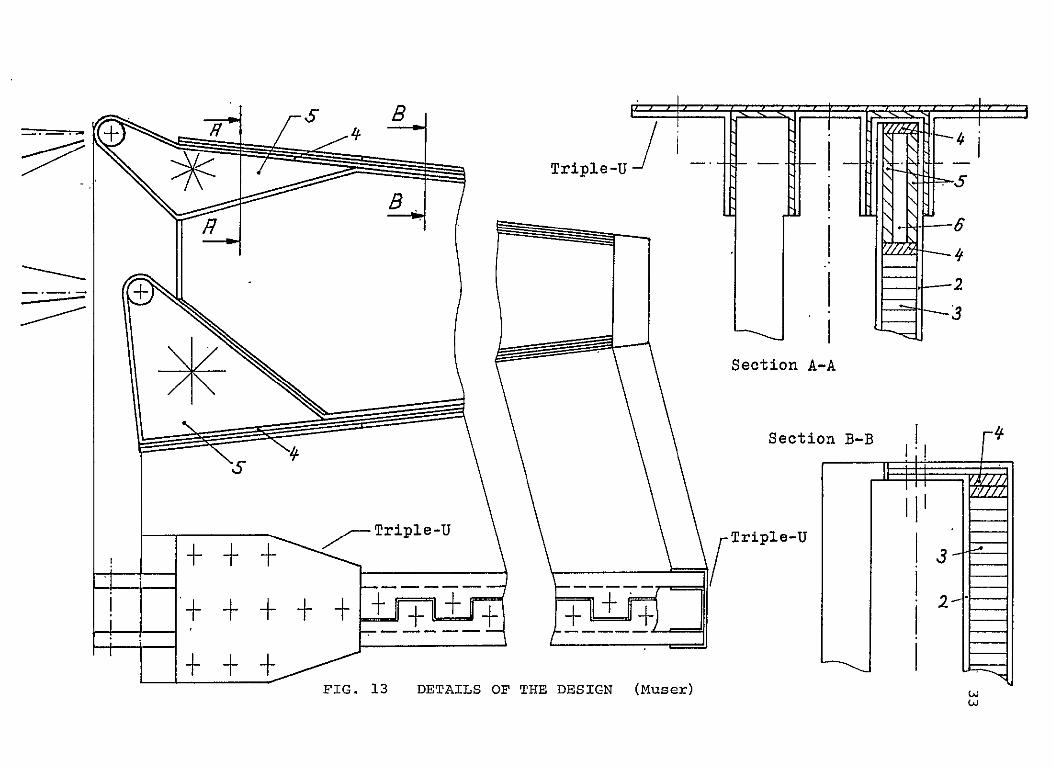
Triple-U .. .. .
Section A-A
Section B-B
Triple-Uiple-U
FIG. 13 DETAILS OF THE DESIGN (Muser)
I