NASA TECHNICAL NOTE · Unclassified - Unlimited I 1. Report No. I ... from exceeding a 3g design...
65
NASA TECHNICAL NOTE *o 0 M d AERODYNAMIC A N D DEPLOYMENT CHARACTERISTICS OF MULTISTAGE CANOPY AND SUSPENSION-LINE REEFING SYSTEMS FOR A TWIN-KEEL ALL-FLEXIBLE PARAWING by Hurry Le Morgun, Jr., und Austin D. McHutton <? Lungley Reseud Center Humpton, 'vu. 23365 , I .' NATIONAL AERONAUTICS AND SPACE ADMINISTRATION WASHINGTON, D. C. JULY 1971 I .- _. - - https://ntrs.nasa.gov/search.jsp?R=19710021272 2018-07-06T08:08:00+00:00Z
Transcript of NASA TECHNICAL NOTE · Unclassified - Unlimited I 1. Report No. I ... from exceeding a 3g design...

NASA TECHNICAL NOTE
*o 0 M
d
AERODYNAMIC AND DEPLOYMENT CHARACTERISTICS OF MULTISTAGE CANOPY AND SUSPENSION-LINE REEFING SYSTEMS FOR A TWIN-KEEL ALL-FLEXIBLE PARAWING
by Hurry Le Morgun, Jr., und Austin D. McHutton <?
Lungley Reseud Center Humpton, 'vu. 23365
, I .'
N A T I O N A L AERONAUTICS A N D SPACE A D M I N I S T R A T I O N W A S H I N G T O N , D. C. JULY 1971
I . - _. - -
https://ntrs.nasa.gov/search.jsp?R=19710021272 2018-07-06T08:08:00+00:00Z

TECH LIBRARY KAFB, NM
17. Key Words (Suggested by Authoris) )
Twin-keel all-flexible parawing Multistage reefing system Aerodynamic and deployment characterist ics
I 111111 11111 lllll lllll lllll1111111111 Ill Ill
~~
18. Distribution Statement
Unclassified - Unlimited
2. Government Accession NO. I 1. Report No. I NASA TN D-6306 4. Title and Subtitle
AERODYNAMIC AND DEPLOYMENT CHARACTERISTICS OF MULTISTAGE CANOPY AND SUSPENSION-LINE REEFING SYSTEM FOR A TWIN-KEEL ALL-FLEXIBLE PARAWING
7. Authork)
Harry L. Morgan, Jr., and Austin D. McHatton
20. Security Classif. (of this page) 19. Security Classif. (of this report)
Unclassified Unclassified
9. Performing Organization Name and Address
NASA Langley Research Center Hampton, Va. 23365
12. Sponsoring Agency Name and Address
National Aeronautics and Space Administration Washington, D.C. 20546
15. Supplementary Notes
Technical Film Supplement L-1086 available on request.
21. NO. of Pages 22. Price*
$3.00 -
60
0 L 3 3 5 L 0 - 3. Recipient's \ a u r , ~ ,w.
5. Report Date July 1971
6. %,-forming Gr2:snization Code
8. Performing Organization Report No.
L-7567 10. Work Unit No.
117 _ _ . .~ . .
11. Contract or Grant No.
13. Type of Report and Period Cavered
Technical Note -
14. Sponsoring Agency Code
16. Abstract
The present investigation was conducted to determine the aerodynamic and deployment characterist ics of a twin-keel all-flexible parawing rigged with several variations of a multistage canopy and suspension-line reefing system. Each variation consisted of four stages of suspension-line reefing with o r without some form of canopy reefing during the f i rs t stage. A theoretical analysis w a s made initially to determine design values for the resultant-force coefficient and the lift-drag ratio which would prevent the peak deployment load from exceeding a 3g design limit during each stage of the deployment sequence. aerodynamic data were obtained from wind-tunnel tes t s of 9.29-mz (100-ft2) wings rigged with various amounts of canopy and suspension-line reefing. Several reefing systems were then selected which had experimental values for the resultant-force coefficient and the lift- drag ratio as close as possible to the design values for each stage. Several 37.16-mz (400-ft2) wings were rigged with the selected reefing systems and flight-tested to determine their deployment characterist ics. The results of the wind-tunnel and flight tests are pre- sented, and detailed descriptions of the canopy and suspension-line reefing techniques, the wind-tunnel tes ts , and the method used to calculate the theoretical time-history of the deployment load a r e included as appendixes.
Experimental
. For sale by the National Technical Information Service, Springfield, Virginia 221 5 1
AERODYNAMIC AND DEPLOYMENT CHARACTERISTICS
OF MULTISTAGE CANOPY AND SUSPENSION-LINE REEFING SYSTEM
FOR A TWIN-KEEL ALL-FLEXIBLE PARAWING
By Harry L. Morgan, Jr., and Austin D. McHatton Langley Research Center
SUMMARY
The present investigation was conducted to determine the aerodynamic and deploy- ment characteristics of a twin-keel all-flexible parawing rigged with several variations of a multistage canopy and suspension-line reefing system. Each variation consisted of four stages of suspension-line reefing with or without some form of canopy reefing during the first stage. A theoretical analysis was made initially to determine design values for the resultant-force coefficient and the lift-drag ratio which would prevent the peak deploy- ment load from exceeding a 3g design limit during each stage of the deployment sequence. Experimental aerodynamic data were obtained from wind -tunnel tests of 9.29 -m2 (100 -ft2) wings rigged with various amounts of canopy and suspension-line reefing. Several reefing systems were then selected which had experimental values for the resultant-force coeffi- cient and the lift-drag ratio as close as possible to the design values for each stage. Several 37.16-m2 (400-ft2) wings were rigged with the selected reefing system and flight- tested to determine their deployment characteristics.
The results of the flight tests showed that the addition of canopy reefing during the f i r s t stage of deployment caused considerable reduction in the fluttering and buffeting motions of the canopy. to the next was very smooth except for severe oscillatory motions which occurred during the fourth stage of deployment. Additional tests of a reefing system with a modified fourth-stage rigging showed considerable reduction in the fourth-stage oscillations. For most of the reefing systems tested, the peak deployment load during the initial opening was slightly more than the 3g design limit, as predicted by the theoretical analysis. The peak deployment loads resulting from the disreefs of the canopy and suspension-line reefing stages were generally less than the 3g design limit, but greater than the loads pre- dicted by the theoretical analysis.
The glide transition from one stage of the suspension-line reefing
INTRODUCTION
In recent years, the National Aeronautics and Space Administration has conducted many in-house and contractual investigations to determine the aerodynamic and deploy- ment characteristics of all-flexible parawings. The results of these investigations showed that most all-flexible parawings open very rapidly, and thereby, high shock loads a r e created during deployments at all but very low dynamic pressures. From the early development of all -flexible parawings, i t was recognized that the needed deployment technology had to be developed before parawings could meet the requirements regarding the deployment loads of most manned spacecraft and personnel descent systems. To obtain the needed deployment technology, the Langley Research Center undertook a con- tractual effort to develop large-scale parawings with flat-pattern a reas up to 371.6 m2 (4000 ft2) capable of recovering 26.7-kN (6000-Ib) payloads deployed a t dynamic pres- sures up to 4.79 kN/m2 (100 Ib/ft2). The results of this contractual effort a r e presented in references 1 and 2.
A prime objective of the large-scale parawing program was to develop a reefing system that could prevent the maximum opening force during deployment from exceeding a 3g design limit (a force equal to three t imes the payload weight). The multistage skirt reefing system developed to meet the 3g design limit was similar in principle to the skir t reefing technique used to reef parachutes as described in reference 3. Although the skir t reefing system developed was successfully tested a t the most severe test conditions, it was not entirely satisfactory. The small inlet a r eas of the reefed canopy during the initial stage of deployment caused the inflation time to increase and thereby excessive fluttering and buffeting motions were produced in the canopy. The large payout of suspen- sion lines (extending lines to their gliding-flight lengths) which constituted the final stage of deployment caused the peak deployment load to exceed the design limit, and it also caused the wing-payload system to oscillate severely.
Near the end of the contractual effort, an in-house effort was initiated to develop and test a multistage canopy and suspension-line reefing system. This reefing system was designed to reduce the fluttering and buffeting motions of the canopy during the ini- tial stage of deployment and to reduce the oscillatory motions of the wing-payload system during the remaining stages of deployment. Skirt reefing controls the canopy shape by routing a reefing line through reefing rings attached to the skir t of the canopy; whereas, suspension-line reefing controls the canopy shape by tying all the suspension lines together a t some point between the canopy and the payload. Canopy reefing reduces the drag a rea of the canopy by retaining (sacking up) a portion of the canopy o r covering the inflated canopy with a large-diameter reefed disk. The present investigation was con- ducted to determine the aerodyna.mic and deployment characteristics of a twin-keel all-
2

flexible parawing rigged with several variations of the multistage canopy and suspension- line reefing system. with or without some form of canopy reefing during the f i r s t stage. A 3g design limit was also imposed during this investigation in order to obtain results comparable with those obtained during the development of the multistage skirt reefing system.
(100-ft2) wings in the Langley 300-MPH 7- by 10-foot tunnel and from flight tests of 37.16-m2 (400-ft2) wings at the Plum Tree Island Air Force Range. tions of the canopy and suspension-line reefing techniques, the wind-tunnel tests, and the method used to calculate the theoretical t ime history of the deployment loads are included as appendixes.
Each variation consisted of four stages of suspension-line reefing
2 The data presented in this report were obtained from wind-tunnel tests of 9.29-m
Detailed descrip-
SYMBOLS
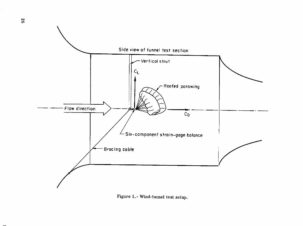
The lift and drag coefficients obtained from the tunnel tests a r e presented with respect to the wind-axes system as shown in figure 1. The reference a rea used in the reduction of the wind-tunnel data w a s the flat-pattern canopy a rea of 9.29 m2 (100 ft2). The deployment loads were measured during the flight tests by a load link located a t the wing-payload attachment point. These data were nondimensionalized and presented as deployment-force coefficients, which used as a reference area a flat-pattern canopy area of 37.16 m2 (400 ft2). Measurements and calculations were made in the U.S. Customary Units. values given parenthetically in the U.S. Customary Units.
They are presented in the International System of Units (SI) with the equivalent
CD drag coefficient, Drag/qS
C F deployment -force coefficient, F/@
CL lift coefficient, Lift/qS
CR resultant -force coefficient, Resultant force/qS, ,/- F deployment load, N (lb)
L/D lift-drag ratio, CL/CD
Z suspension-line length between staging confluence points, m (ft)
3
S
t
K
LE
TE
TEC
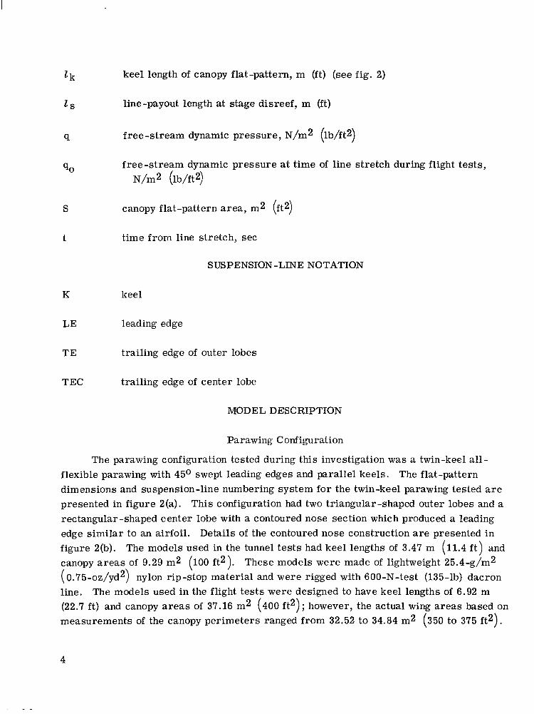
keel length of canopy flat-pattern, m (ft) (see fig. 2)
line-payout length at stage disreef, m (ft)
free-stream dynamic pressure, N/m2 (lb/ft2)
free-stream dynamic pressure a t time of line stretch during flight tests, N/m2 (lb/ft2)
canopy flat-pattern area, m2 (ft2)
time from line stretch, sec
SUSPENSION-LINE NOTATION
keel
leading edge
trailing edge of outer lobes
trailing edge of center lobe
MOD EL DESCRIPTION
Parawing Configuration
The parawing configuration tested during this investigation was a twin-keel all- flexible parawing with 45O swept leading edges and parallel keels. The flat-pattern dimensions and suspension-line numbering system for the twin-keel parawing tested a r e presented in figure 2(a). This configuration had two triangular-shaped outer lobes and a rectangular-shaped center lobe with a contoured nose section which produced a leading edge similar to an airfoil. Details of the contoured nose construction are presented in figure 2(b). The models used in the tunnel tes ts had keel lengths of 3.47 m (11.4 f t ) and canopy areas of 9.29 m2 (100 ft2). These models were made of lightweight 25.4-g/m2 ( 0.75-oz/yd2) nylon rip-stop material and were rigged with 600-N-test (135-lb) dacron line. (22.7 ft) and canopy areas of 37.16 m2 (400 f t2) ; however, the actual wing areas based on measurements of the canopy perimeters ranged from 32.52 to 34.84 m2 (350 to 375 ft2).
The models used in the flight tests were designed to have keel lengths of 6.92 m
4
The flight models were made of 76.3-g/m2 ( 2.25-oz/yd2) nylon rip-stop material and were rigged with either 1.11- or 4.45-kN-test (250- or 1000-lb) dacron line. The materials used to construct the wind-tunnel and flight models had permeabilities of 0.17 and 0.08 m3/sec/m2 (33.5 and 16.0 ft3/min/ft2), respectively, at a differential pressure of 25.4 c m (10 in.) of water.
Reefing System
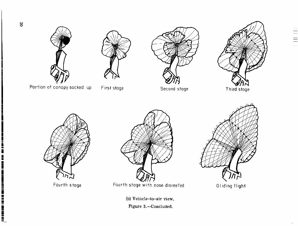
The multistage reefing system flight-tested during this investigation consisted of four stages of suspension-line reefing with or without some form of canopy reefing during the first stage of deployment. Suspension-line reefing controlled the canopy shape by tying the suspension lines together with a reefing line at various intervals between the wing and payload and then cutting the reefing lines sequentially to produce a steplike increase in lift-drag ratio and resultant-force coefficient. In an effort to reduce the fluttering and buffeting motions of the canopy during the first stage of deployment, a form of canopy reefing was added to the reefing system. It consisted of retaining (sacking up) a portion of the canopy or covering the inflated canopy with a large-diameter reefed disk. In order to provide a more symmetric and evenly loaded canopy, the nose section w a s reefed during the initial stages of deployment and was disreefed a t the time of either third-stage disreef or during the fourth stage of the deployment sequence. Sketches illustrating a typical deployment sequence and showing the inflated canopy shape at each deployment stage as viewed from the ground and from the payload a r e presented in fig- ure 3. presented in appendix A.
Detailed descriptions of the canopy and suspension-line reefing techniques a r e
TESTS AND APPARATUS
Wind-Tunnel Tests
Tests and procedures.- Pr ior to the wind-tunnel tests, a theoretical analysis w a s made to determine design values for the resultant-force coefficient and the lift-drag ratio which would prevent the peak deployment load from exceeding the 3g design limit during each stage of the deployment sequence. A detailed description of the theoretical method used is presented in appendix B. The mathematical model used to simulate the actual flight system was a simple point-mass system, and therefore, elastic properties of the coupled wing-payload system were neglected in the analysis. After the theoretical analysis, 9.29-m2 (100-ft2) wings were tested in the wind tunnel to determine the rigging for each of four stages of suspension-line reefing, which included five variations of the f i r s t stage. Tests were also made to determine the effects of sacking up various portions of the canopy and of covering the canopy with various-diameter reefed disks during the
5
first and second stages of the suspension-line reefing. A detailed description of the wind- tunnel tests is presented in appendix C. After an analysis of the tunnel data, several reefing systems were selected and flight tested which had experimental values for the resultant-force coefficient and the lift-drag ratio as close as possible to the design values for each stage.
Test facilitv and test conditions.- The wind-tunnel tes ts were made in the 5.18-m (17-ft)- test section of the Langley 300-MPH 7- by 10-foot tunnel by using the test setup shown in figure 1. o r 95.8 N/m2 (0.5, 1.0, or 2.0 lb/ft2) during a particular run, and force data were taken with a six-component strain-gage balance connected to a vertically mounted strut . No jet boundary or blockage corrections were made to the data taken during the tunnel tests.
The tunnel free-stream dynamic pressure was set a t either 23.9, 47.9,
Flight Tests
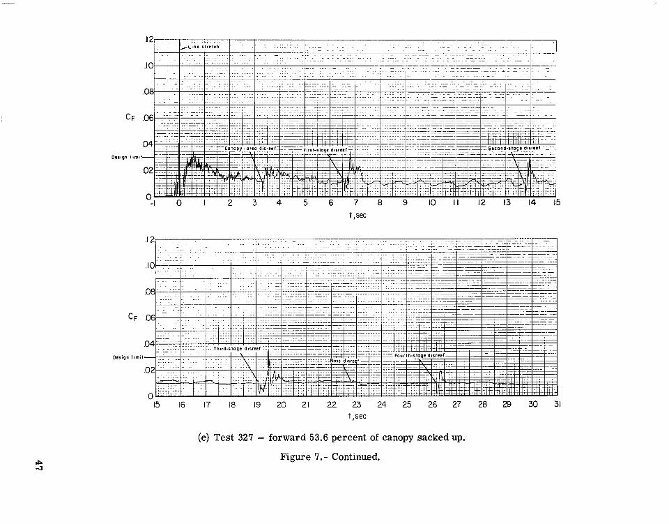
Tests and procedures.- Several flight tes ts were made initially of a 37.16-m (400-ft2) wing rigged with a reefing system composed of four stages of suspension-line reefing and no canopy reefing in order to obtain a base of comparison for the systems with some form of canopy reefing. Flight tests were then made of models that were rigged with a reefing system which had one of five forms of canopy reefing during the initial stage of deployment. The five forms tested consisted of (1) sacking up the aft 46.4 percent of the canopy, (2) sacking up the forward 53.6 percent of the canopy, (3) sacking up the center lobe, (4) sacking up the outer lobes, and (5) covering the canopy with a 0.5lk-diameter reefed disk. Each reefing system was flight-tested with the wing attached to an uninstrumented payload to check the system for proper functioning during the deployment sequence before testing the sa-me system on one of the more expensive instrumented payloads.
2
During each flight test, the vehicle was released from a helicopter a t a launch alti- tude of approximately 1.28 km (4200 ft) and fell for about 10 seconds to a deployment altitude of about 762 m (2500 ft) and a free-stream dynamic pressure of approximately 2.73 kN/m2 (57.0 lb/ft2). During each test, ground-to-air motion pictures were taken by two cameras which ran at 24 and 64 frames per second. The ground-to-air and vehicle-to-air (taken by the camera in the payload) motion pictures were analyzed after each test to determine the deployment event times, the cause of any malfunction that may have occurred, and the overall stability and performance of the reefing system during deployment. adjust the total system weight (wing plus payload weight) to obtain a wing loading of 35.9 N/m2 (0.75 lb/ft2). The weight adjustments were necessary because of the varia- tion in the actual wing a reas of the flight-test models. Before each wing was packed into a deployment bag, the wing-tip control lines were adjusted so that the wing would turn
P r io r to each test, iron plates were added to the nose of the payload to
6
I
either right or left during the glide stage of deployment. The control-line adjustments helped to prevent the vehicle from flying out of the test range area. A detailed descrip- tion of the packing procedures used for the flight tes ts is presented in appendix A.
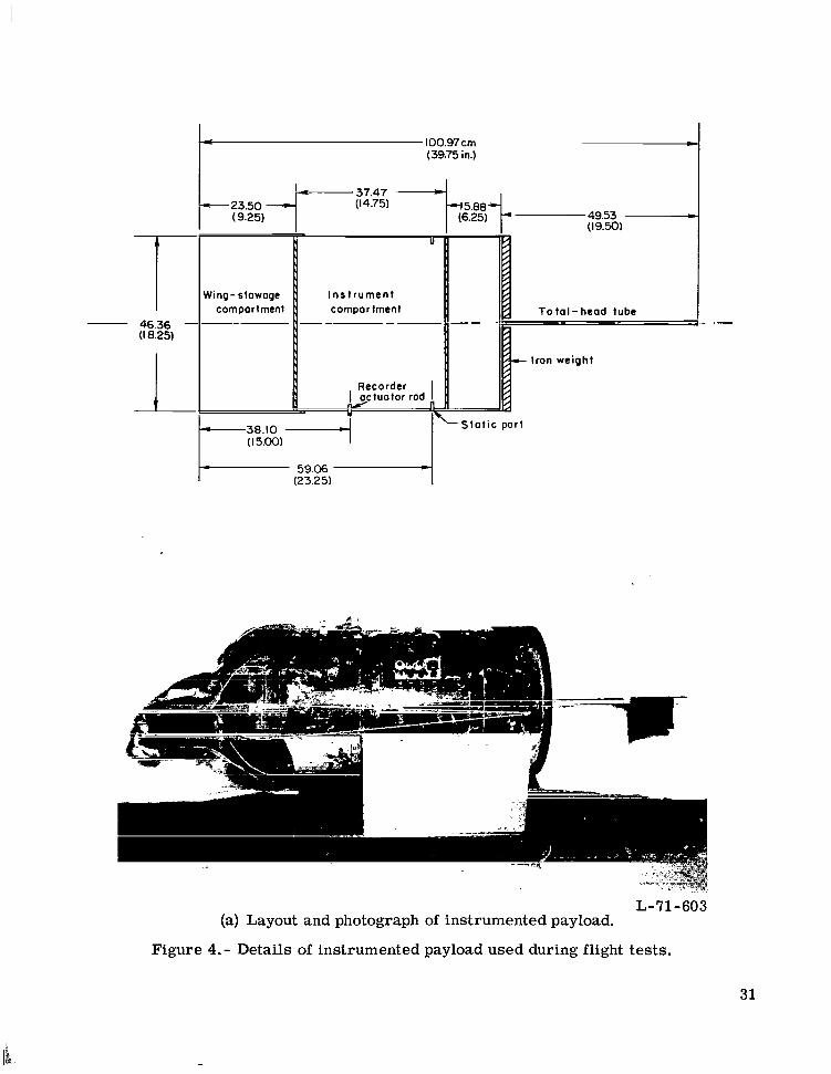
Test area and test vehicles.- - The flight tests were conducted a t the Plum Tree Island Air Force Range, which is located in the coastal tideland area near the Langley Research Center. This location w a s chosen because it had adequate land area to perform the desired flight tests safely. Both the instrumented and uninstrumented (inert) pay- loads had the same overall dimensions and weights. Two instrumented payloads were used during the flight tests, and they differed to some degree in the type and amount of onboard equipment. The details of the f i rs t instrumented payload a r e presented in fig- ure 4(a), and an accompanying location diagram and list of the instruments is presented in figure 4(b). The basic instruments in the first payload were a strain-gage load link to measure deployment loads, a pressure transducer with an externally mounted total- head tube to measure free-stream dynamic pressure, a recording oscillograph to record the output from the load link, and a motion-picture camera to photograph the wing during deployment. The second instrumented payload had essentially the same instruments as the f i rs t except a magnetic tape recorder was used instead of a recording oscillograph and the load link was mounted externally at the confluence point of the canopy and payload r i se rs . The second payload was also equipped with wing-tip control-line equipment powered by an electric winch system, which was controlled by a radio command receiving unit. This additional equipment provided for a more convenient and safe test operation by allowing the ground-based test conductor to s teer the parawing away from undesirable landing points.
PRESENTATION O F RESULTS
Wind-Tunnel Tests
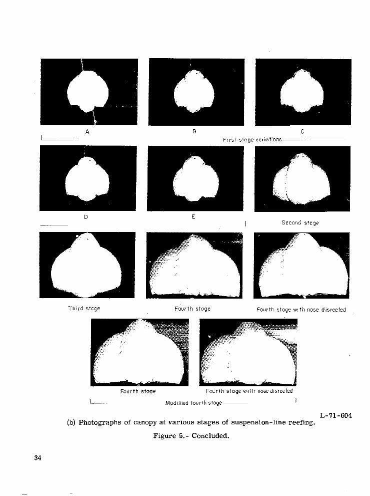
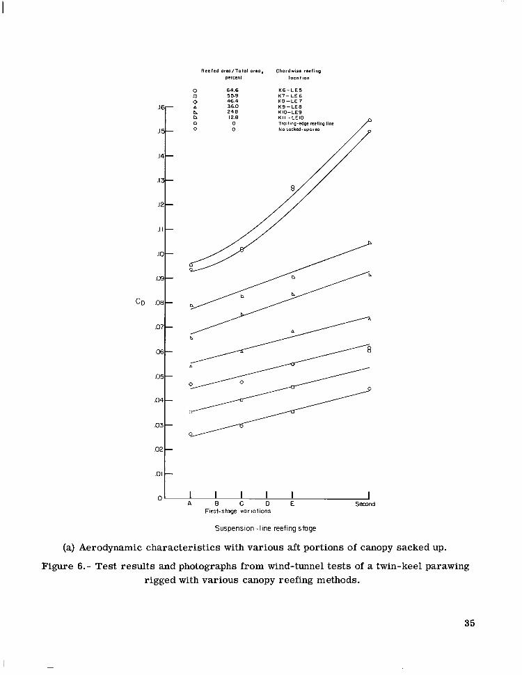
The results from the wind-tunnel tests of the suspension-line reefing and canopy reefing methods a r e presented in figures 5 and 6, respectively. A se t of photographs showing the inflated canopy shape as viewed from a location downstream of the test setup is presented together with the aerodynamic data for each method. Each photograph in a set of photographs was taken from the same downstream location to show the comparative change in the projected wing a rea with the change in the amount of reefing. The test models developed essentially no lift when rigged with the line lengths for any of the f i rs t - stage variations and the second stage of the suspension-line reefing; therefore, only the drag coefficients w e r e computed and presented in the test results. The line-segment and line-payout lengths for each stage of the suspension-line reefing a r e presented in table I.
7

Flight Tests
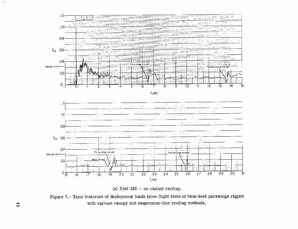
A summary of the results obtained from eight flight tes ts is presented in table 11, and the corresponding time-histories of the deployment loads are presented in figure 7. Data a r e presented for two flight tests of 37.16-m2 (400-ft2) twin-keel parawings rigged with a reefing system composed of four stages of suspension-line reefing and f o r six flight tes ts of the same wings also rigged with some form of canopy reefing during the first stage of deployment. The latter six tests consisted of two tests with the aft 46.4 percent of the canopy sacked up, one test with the forward 53.6 percent sacked up, one test with the center lobe sacked up, one test with the outer lobes sacked up, and one test with a O.5Zk-diameter reefed disk covering the canopy. During two of the latter six tests, the wings were rigged with a modified fourth stage of the suspension-line reefing. The peak deployment load after nose disreef is not presented in ta.ble I1 because the value of the load was negligible compared with the peak loads after the staging disreefs. Although a time-history of the dynlimic pressure was recorded during each flight test, the dynamic pressure only a t the time of line stretch (time of maximum dynamic pressure) is presented in table II. The validity of the dynamic-pressure data after line stretch was doubtful because of the effects of the deployment forces on the pressure transducer and because of the misalinement of the payload with respect to the flight path.
DISCUSSION
Wind-Tunnel Tests
Suspension-line reefing.- Table 111 lists the design values of the lift-drag ratio and the resultant-force coefficient used to calculate the theoretical time-history of the deploy- ment load and the experimental values obtained from the tunnel tests.
The design and experimental values show reasonably good agreement in view of the relative difficulty encountered in rigging the wing to form an inflated canopy shape that produced given values of both the lift-drag ratio and the resultant-force coefficient. Addi- tional suspension-line rigging tests were made during the present investigation to modify the line-payout lengths of the third stage because of severe oscillatory motions which occurred immediately after the third -stage disreef during several early flight tests. A more detailed analysis of the oscillatory motions a r e discussed in the section on the flight-test results. The revised line lengths were obtained by adjusting the line lengths between the wing and the fourth-stage confluence point so that the third stage would have less and the fourth stage more line to payout at disreef than they had with the original rigging. The results of the additional rigging tes ts a r e presented in figure 5 and table I as those for a modified fourth stage.
8
Canopy reefing.- The data presented in figure 6 were obtained by sacking up various portions of the canopy and also by covering the inflated canopy with various-diameter reefed disks. The test results fo r each method showed that with a fixed amount of canopy reefing, the drag coefficient of the inflated canopy increased as the suspension lines were lengthened to increase the inlet area. It could not be determined from the wind-tunnel data taken whether or not the increase in drag coefficient and inlet area would have caused an increase in the peak deployment loads because no measurements were made to deter- mine the corresponding change in the inflation time. The inflation t imes were not mea- sured primarily because there were no methods available to correlate the inflation times obtained from tunnel tes ts of small models with infinite wing loadings and those obtained from flight tests of larger models with finite wing loadings.
The test results presented in figures 6(a) and 6(c) showed that the range of values for the drag coefficient obtained by sacking up the aft and then the forward portions of the canopy were approximately the same. The inflated canopy configurations were more nearly symmetric with a given percent of the forward portion of the canopy sacked up than with the same percent of the aft portion of the canopy sacked up, as illustrated in figures 6(d) and 6(b), respectively.
As shown in figure 6(e), the values for the drag coefficient that were obtained by sacking up the outer lobes were lower than those obtained by sacking up the center lobe. Lower values for the drag coefficient were expected because a larger percent of the total wing area w a s reefed with the outer lobes sacked up than with the center lobe sacked up. An increase in the suspension-line lengths caused a relatively small change in the drag coefficient with the outer lobes sacked up and was believed to be due primarily to the small increase in inlet area. lobes sacked up, the inlet area of the inflated canopy was primarily a function of the trailing-edge line lengths and therefore, an increase in the suspension-line lengths caused only a small increase in the inlet area. A s shown in figure 6(f), with the outer lobes sacked up, the center lobe formed a horseshoe-shaped configuration which had a tendency to oscillate at relatively high frequencies about the confluence point of the suspension lines. As also shown in figure 6(f), with the center lobe sacked up, one outer lobe twisted below the other outer lobe, and thereby tightly confined the sacked-up center lobe. Because of this tight confinement, a spring-loaded pilot parachute was sacked up with the center lobe during the flight tests to help push the reefing disk through the twisted outer lobes after disreef of the center lobe.
As shown in appendix A, with the nose reefed and the outer
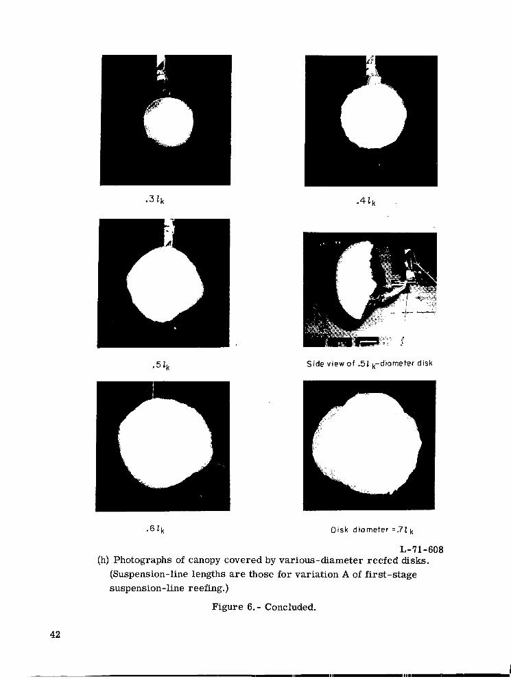
As shown in figure 6(g), covering the inflated canopy with various-diameter reefed disks produced an almost l inear increase in the drag coefficient with an increase in staging. Air pockets which formed along the leading edges of the inflated canopy caused the canopy to pull out of the reefed disks when the disk and canopy suspension lines were
9

lengthened beyond those of first-stage variation C for the 0.32k- and 0.4Zk-diameter disks and those of the first-stage variation E for the 0.52k- and O.6Zk-diameter disks. It was believed that the addition of more disk suspension lines to prevent the formation of the air pockets would have caused an undesirable increase in the weight of the disk. As illus- trated in figure 6(h), the shape formed by covering the inflated canopy with a reefed disk was very similar to that of a typical low-porosity inflatable-balloon decelerator which has characteristic spin-up and stability problems. (See ref. 3.)
Selection of reefing systems ~- for flight tests.- As stated in appendix A, the values of the drag coefficients used to calculate the theoretical time history of the deployment load were 0.05 for the f i r s t stage of deployment with a portion of the canopy reefed and 0.10 for the f i r s t stage after canopy disreef. The results of the wind-tunnel tests showed that the inflated canopy had a value for the drag coefficient of approximately 0.10 when rigged with the line lengths for variation A of the first-stage suspension-line reefing. It was decided, therefore, to rig each flight model with variation A line lengths for the f i rs t stage. Other variations of the f i r s t stage were not flight-tested during this investigation because it was a rather time-consuming task to change the locations of the suspension- line reefing rings and the sleeves used to store the first-stage payout line.
An examination of the wind-tunnel data was also made to determine the particular amount of each form of canopy reefing flight-tested. The selection of aft and forward portions of the canopy that were sacked up during the flight tes ts was made by determining the chordwise location which divided the canopy so that sacking up the aft and then the forward portions of the canopy produced drag coefficients with values as close to 0.05 as possible. (See figs. 6(a) and 6(c).) The chordwise location selected was the K8-LE7 position, which divided the canopy with 46.4 percent of the canopy aft and 53.6 percent of the canopy forward of that position. The wind-tunnel data also showed that covering the canopy with a 0.5Zk-diameter reefed disk produced a drag coefficient with a value closest to 0.05 of the five disks tested; therefore, that size disk was chosen for the flight tests. Flight tests were also made by sacking up the center lobe and then the outer lobes, which produced approximately the same variation in the value of the drag coefficient as that obtained by sacking up the selected aft and forward portions of the canopy.
Although the wind-tunnel data could not be used to predict the dynamic stability of the selected reefing systems, i t was useful in the selection of reefing systems which had terminal flight conditions as nearly as possible like those for the theoretical model for each deployment stage.
Flight Tests
The deployment stability of each reefing system was determined primarily by an analysis of both the ground-to-air and the vehicle-to-air motion-picture films. A film
10

supplement (L-1086) showing the overall stability and glide transition of the wing-payload system during the flight test of the reefing system with the forward 53.6 percent of the canopy sacked up is available on loan from the Langley Research Center. A request card and a description of the film a r e included at the back of this document.
Behavior and stability of reefing system. - No particular problems were encountered in the functioning of the disreef mechanisms of either the canopy o r the suspension-line reefing stages during any of the flight tes ts performed. During the tests of the systems with canopy reefing, there appeared to be sufficient canopy forces in the inflated portion of the canopy to cause the sacked-up portion to deploy rapidly after disreef. The greatly distorted canopy shapes that occurred during the inflation phase of the initial deployment stage caused the canopy to spin relative to the payload. canopy caused the column of suspension lines between the first-stage confluence point and the payload attachment point to twist, which is a problem characteristic of most low- porosity and symmetrically shaped decelerators. unwound during the deployment sequence, and even when the lines were tightly twisted, the payout of line a t each stage disreef did not appear to be affected. The payout of line was not affected because the line-payout lengths were stored in sleeves which prevented the lines from becoming tangled with the line-segment lengths. Covering the canopy with a 0.5Zk-diameter reefed disk produced a spherical canopy shape, which caused the canopy to spin more rapidly than during previous tests. The more rapid spinning motion caused the column of lines to twist more tightly; however, there were still no noticeable effects on the disreefing characteristics.
The spinning motion of the
The twisted line column gradually
The results of the flight tests showed that the addition of canopy reefing caused con- The results also siderable reduction in the fluttering and buffeting motions of the canopy.
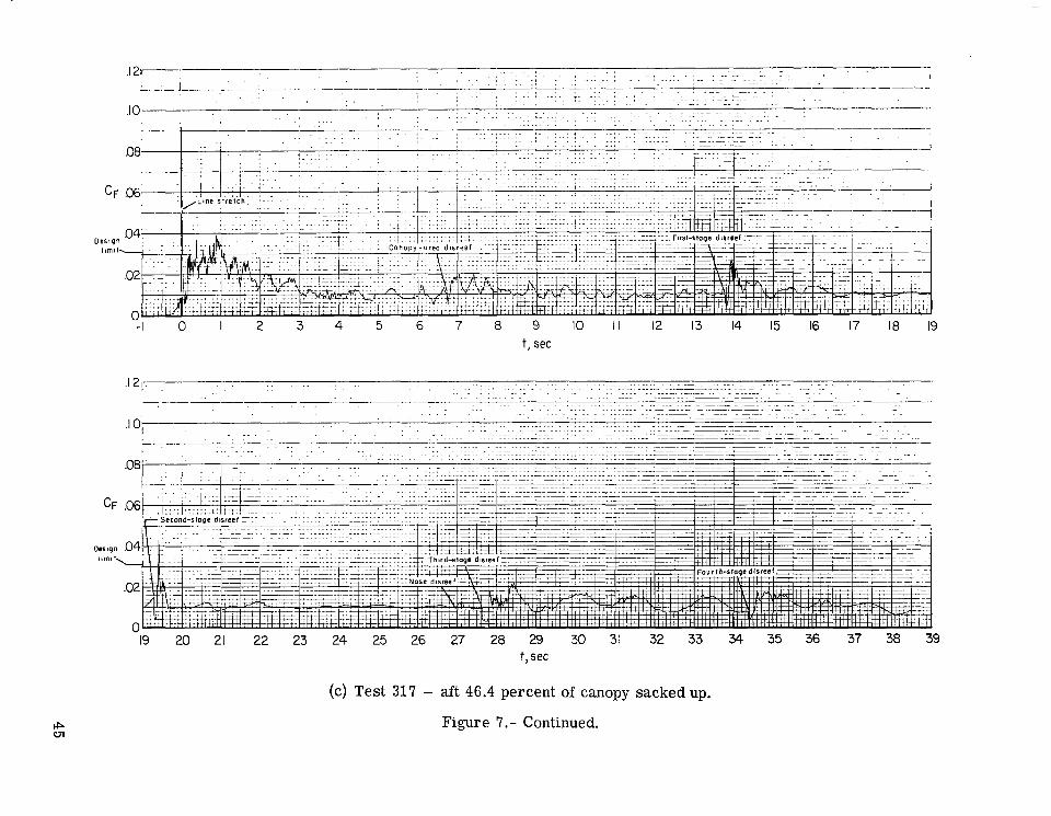
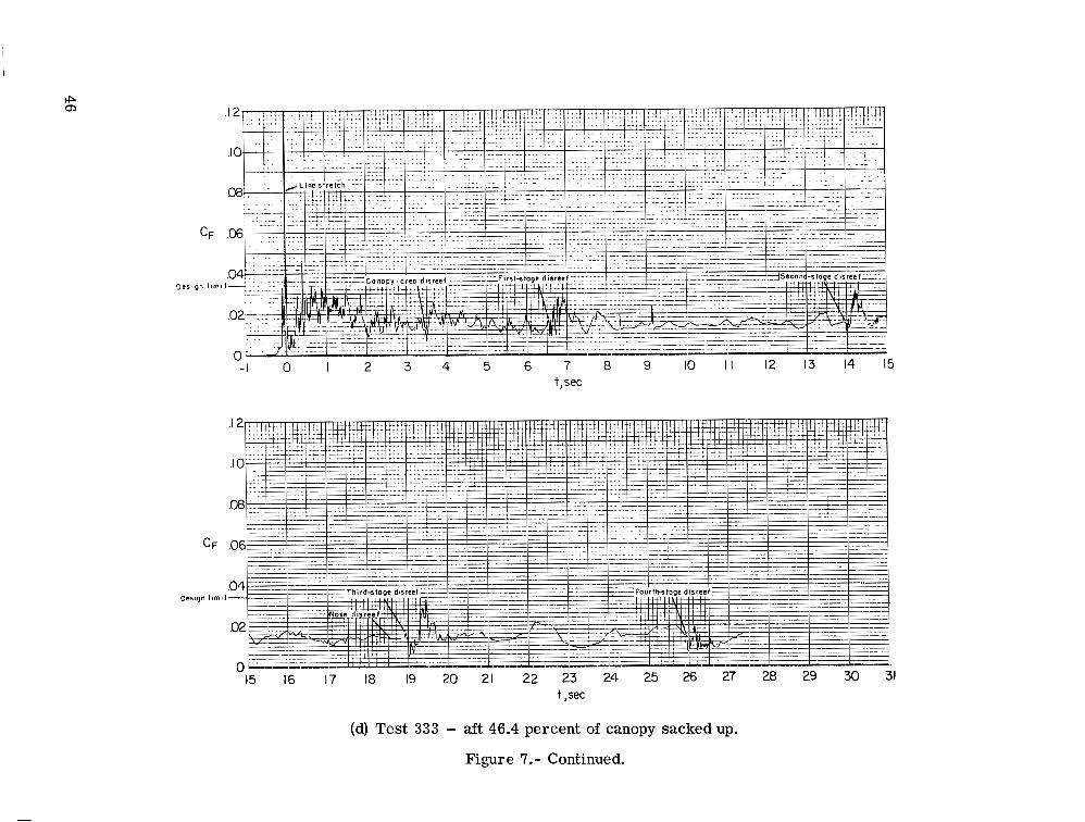
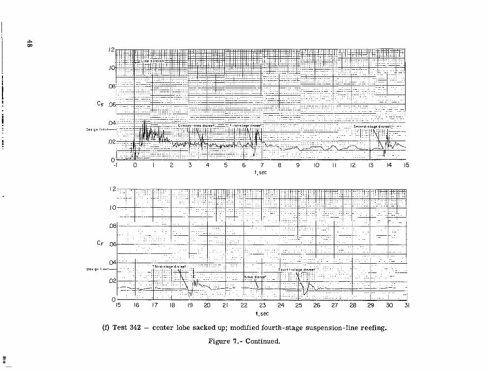
showed that the glide transition from one stage of the suspension-line reefing to the next was very smooth except during the fourth stage of the systems without the modified fourth- stage rigging. An analysis of the fi lms taken during the tes ts of the systems without the modified rigging showed that the large payout of line a t third-stage disreef caused a rapid increase in the wing-to-payload distance and in the inflated shape of the canopy. rapid increases in distance and shape caused the wing-payload system to oscillate severely, as exemplified by the magnitude of the oscillations in the curves of the deploy- ment loads presented in figures 7(c) and 7(d). modified fourth-stage rigging showed considerable reduction in the fourth-stage oscilla- tions, as evidenced by the smoothness in the curves of the deployment loads presented in figures 7(f) and 7(h).
The
The tests of the reefing systems with a
Deployment loads and canopy damage.- For most of the reefing systems tested, the peak deployment load during the initial opening was slightly more than the 3g design limit, as predicted by the theoretical analysis. The peak deployment loads resulting from the
11
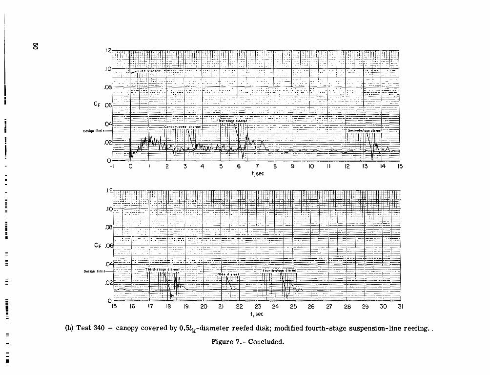
disreefs of the canopy and suspension-line reefing stages were generally less than the 3g design limit, but greater than the loads predicted by the theoretical analysis. There was also considerable scatter in the peak deployment loads during a particular stage of the suspension-line reefing from one test to the next. Data scatter is a problem character- istic of most inflating decelerator devices and is usually the result of slight variations in the deployment conditions or in the inflation of the canopy. The canopy reefing system that involved covering the canopy with a 0.52k-diameter reefed disk produced the lowest peak deployment loads during the initial stage of deployment of the systems tested. Lower deployment loads were not expected with that canopy reefing method because the reefed disk reduced the volume of the inflated canopy without an accompanying reduction in inlet area. Compared with the other methods with equivalent drag a reas , covering the canopy with a reefed disk should have caused shorter inflation times and, therefore, higher deployment loads. However, the added weight of the disk used to cover the canopy could have caused the inflation time to increase and thereby produced lower deployment loads.
No attempts were made during this investigation to reduce the extraction velocity of the deployment bag from the payload; therefore, high deployment loads occurred at line stretch. suspension-line reefing system as compared with the skirt reefing system because of the improved distribution of mass attributed to the suspension-line reefing rings.
(See table 11.) However, the line stretch loads should be lower for the
The peak deployment loads experienced by several of the more heavily loaded suspension lines were measured with mechanical and electrical load links during several flight tests. The small amount of line-load data obtained showed considerable scatter and was therefore not included in this report. It is reasonable to assume, however, that the peak line loads did not exceed a force necessary to break a 1.11-kN-test (250-lb) dacron line because no lines were broken during the tests of the wings rigged with that type of line. If the load time history were known for each suspension line, the weight of each line could be reduced by sizing the portion of the line between the wing and the confluence point of the highest loaded stage to ca r ry the peak line load and by sizing the remaining portion of line to ca r ry the next highest load.
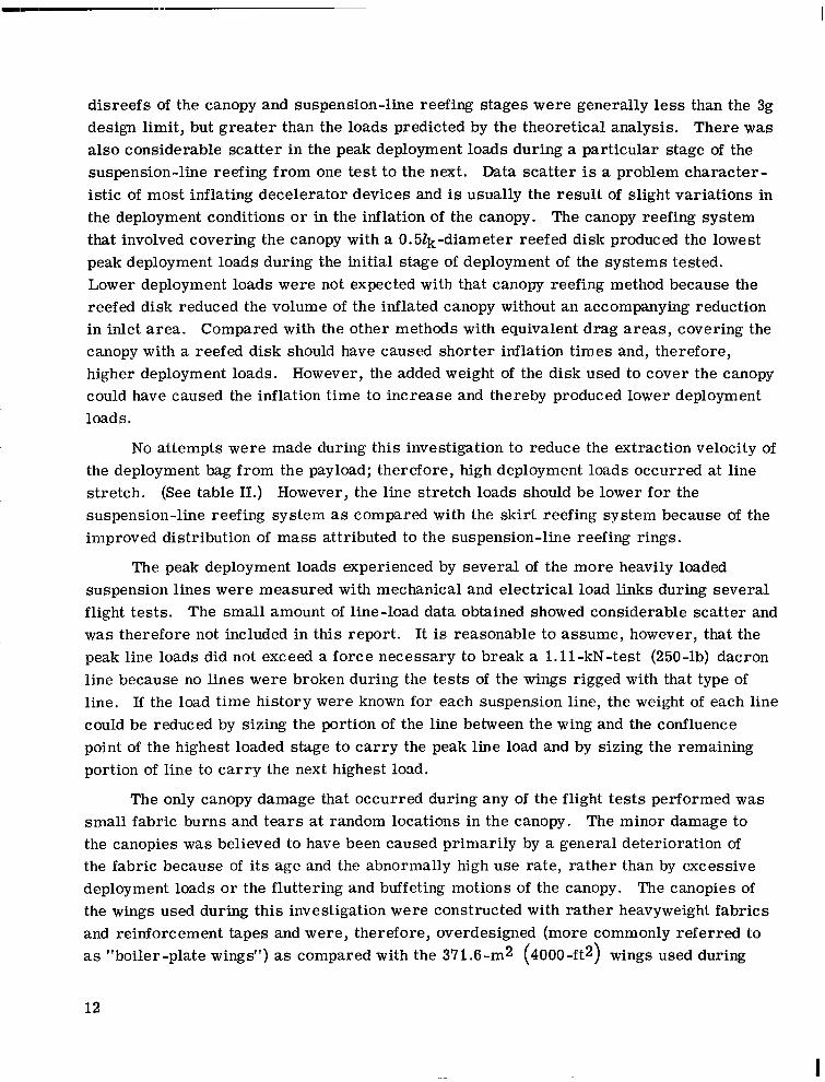
The only canopy damage that occurred during any of the flight tes ts performed was small fabric burns and tears a t random locations in the canopy. The minor damage to the canopies was believed to have been caused primarily by a general deterioration of the fabric because of i ts age and the abnormally high use rate, rather than by excessive deployment loads o r the fluttering and buffeting motions of the canopy. The canopies of the wings used during this investigation were constructed with rather heavyweight fabrics and reinforcement tapes and were, therefore, overdesigned (more commonly referred to as "boiler-plate wings") as compared with the 371.6-mz (4000-ft2) wings used during
12
I
the large-scale development program. An assessment of the ability of the reefing systems tested to reduce canopy damage when incorporated on larger size wings could not be made because overdesigned wings were used. It can be stated, however, that the reduction in the fluttering and buffeting motions of the canopy during the initial stage of deployment and the improvement in the glide transition during the subsequent stages of deployment make the multistage canopy and suspension-line reefing system a desirable candidate for investigation on larger size wings. The canopy and suspension-line reefing techniques studied can conceiveably be adapted to most of the flexible-wing devices that may be considered for use in various recovery systems. The amount of staging required for a particular system will depend, of course, on the structural limitations of the system components .
SUMMARY OF RESULTS
The aerodynamic data obtained from the wind-tunnel tests could not be used to pre- dict the dynamic stability of the selected reefing systems. However, the data obtained were useful in the selection of reefing systems which had terminal flight conditions as nearly as possible like those for the theoretical for each deployment stage. of the flight tes ts of the selected reefing systems showed that no particular problems were encountered in the functioning of the disreef mechanisms of either the canopy or suspension-line reefing. The flight-test results also showed that the addition of canopy reefing caused considerable reduction in the fluttering and buffeting motions of the canopy. The glide transition from one stage of the suspension-line reefing to the next was very smooth except for severe oscillatory motions which occurred during the fourth stage of deployment of the systems without the modified fourth-stage rigging. The tes ts of the systems with the modified fourth-stage rigging showed considerable reduction in the fourth-stage oscillations. load during the initial opening was slightly more than the 3g design limit, as predicted by the theoretical analysis. The peak deployment loads resulting from the disreefs of the canopy and suspension-line reefing stages were generally l e s s than the 3g design limit, but greater than the loads predicted by the theoretical analysis.
The results
For most of the reefing systems tested, the peak deployment
Langley Research Center, National Aeronautics and Space Administration,
Hampton, Virginia, May 18, 1971.
13
APPENDIX A
SUSPENSION-LINE AND CANOPY REEFING TECHNIQUES
AND PACKING PROCEDURES
Suspension-Line Reefing
A stage of suspension-line reefing consisted of tying all the canopy suspension lines together a t a given distance from the payload attachment point to form a stage confluence point, thereby shortening the distance from the wing to the confluence point. As indi- cated by the data presented in figure 23 in reference 4, a reduction in the distance from the wing to the confluence point caused a reduction in lift-drag ratio and resultant-force coefficient. To produce a gradual glide transition during deployment required a multi- stage reefing system composed of several stages of suspension-line reefing with the stage reefing lines cut in succession. The suspension lines were tied together at each stage confluence point by a reefing line routed through a dual-hole reefing ring attached to each line. Pyrotechnic linecutters with successive firing t imes were used to cut the reefing lines a t the desired t imes during deployment.
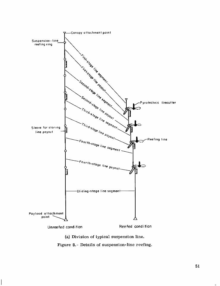
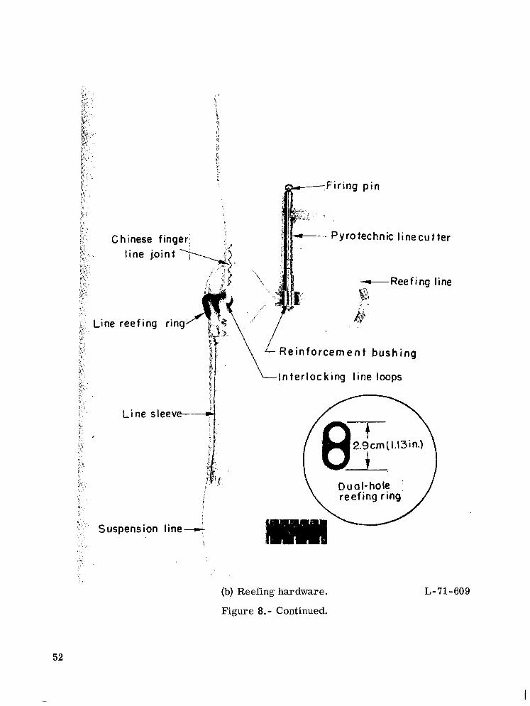
To insure a very desirable uniform loading of the suspension lines between each stage confluence point and the payload attachment point required that all lines between the two points have equal lengths. However, simply tying all the lines together a t a given distance from the payload attachment point did not necessarily result in an inflated canopy shape that produced the desired combination of lift-drag ratio and resultant-force coeffi- cient. To obtain the necessary inflated shape at each stage, the suspension-line lengths were shortened between the stage confluence point and the canopy attachment points. Each line w a s shortened the required amount by attaching an additional dual-hole reefing ring to the line at the correct distance from the stage confluence point and then by routing the stage reefing line through this additional reefing ring. The shortened portion of line was defined as line payout and was stored in a cloth sleeve sewn to the line below the stage confluence point to prevent the payout line from becoming tangled and causing a malfunction a t disreef. Sketches showing a typical suspension line in the unreefed and reefed conditions a r e presented in figure 8(a), and a photograph showing the reefing hard- ware used a t typical stage confluence point is presented in figure 8(b). As shown in figure 8(b), a reinforcement bushing was installed around the pyrotechnic linecutter to relieve the reefing line load on the relatively weak cutter housing. The linecutter was positioned to form an eight-shaped reefing line because the eight-shaped line had four f ree ends when cut instead of just two free ends had the cutter been positioned to form a circular-shaped line. The right and left leading-edge, trailing-edge, and keel suspension lines were located respectively on the right and left side of the eight-shaped reefing line,
14
I

APPENDIX A - Continued
and the lines were selected in the order shown in figure 8(c). The order shown was chosen because i t provided a minimum amount of crisscrossing and rubbing of the sus- pension lines and minimum oscillations of the canopy-payload system a t disreef. A photograph showing a typical flight-test model rigged with four stages of suspension- line reefing is presented in figure 9.
Canopy Reefing
Canopy reefing consisted of retaining (sacking up) a portion of the canopy or cov- ering the inflated canopy with a large-diameter reefed disk. There were an infinite number of variations in the portions of the canopy that could have been sacked up to achieve a specific amount of canopy reefing. However, only four variations were tested during this investigation, and they included sacking up (1) an aft portion of the canopy, (2) a forward portion, (3) the center lobe, and (4) the outer lobes of the canopy of a twin- keel parawing. These four variations were chosen because they appeared to be the most obvious and simple to reef mechanically. with sufficient volume to contain the reefed portion of the canopy w a s used to sack up the desired portion of the canopy. Each disk was reefed by lines routed through single-hole rings attached to the canopy at various points on the perimeter of the a rea to be reefed and through rings attached to the disk. The routing order of the disk reefing lines for each of the four variations that were flight-tested is presented in figure 10. The disks used to sack up a portion of the canopy had 58.42-cm (23-in.) radii and eight reefing rings attached a t equally spaced concentric locations 45.72 cm (18 in.) from the center of each disk. For several flight tests, small-diameter pilot parachutes were connected to the disks and were sacked up inside the reefed disks to aid the disreef and the flyaway of the disks after disreef. which were set to f i re midway between the t imes of line stretch and first-stage disreef.
A small-diameter disk reefed to form a bag
The disk reefing lines were cut by pyrotechnic linecutters
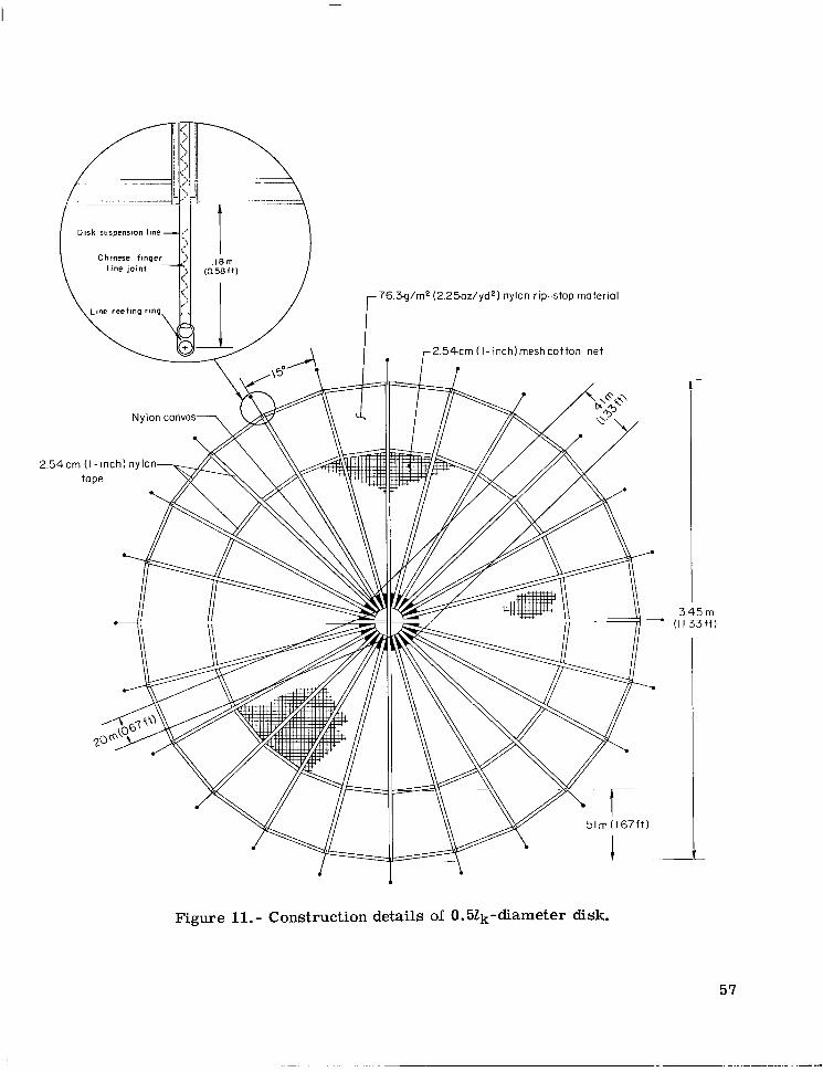
An additional canopy reefing method w a s investigated and involved covering the inflated canopy with a large-diameter reefed disk, which reduced the volume and drag a rea of the canopy and formed a more spherical-shaped configuration. The construction details of the disk used during the flight test of this method a r e presented in figure 11. The chance of canopy damage occurring during deployment in the form of abrasive burns was greater with this method because of the rubbing action between the canopy and the disk. concentric c i rc les with cotton netting material in the a rea formed by the inner c i rc le and with nonporous nylon material in the area between the inner and outer circles. The highly porous netting material also prevented the reefed disk from inflating by itself, and thereby allowed the inflated canopy to enclose the reefed disk completely. A set of disk suspension lines were sewn to the perimeter of the disk and a dual-hole reefing ring
To reduce the abrasive burn damage, the disk was constructed in the form of two
15

APPENDIX A - Continued
was attached to the f ree end of each line. The lengths of the disk suspension lines were all equal and the same as the first-stage length of the leading- and trailing-edge canopy suspension lines. The disk was reefed by an additional reefing line which was routed through the disk reefing rings and selected reefing rings at the first-stage confluence point. This additional reefing line was cut by a separate pyrotechnic linecutter set to fire midway between the times of line stretch and first-stage disreef.
Nose Reefing
Most twin-keel parawings, like the one tested in this investigation, have rather wide center panels and contoured nose sections. For this investigation, suspension lines were added to the trailing edges of the outer and center lobes to provide a more even distri- bution of the total load into the canopy during the initial stages of deployment. For the same reason i t was also desirable to attach suspension lines to the leading edge of the nose section of the center lobe; however, previous tes t s showed that the addition of lines to the nose, in most instances, caused the nose to droop and stall in forward flight. To overcome this disadvantage, the nose section was reefed with a reefing line which was routed through single-hole reefing rings attached to the canopy at various locations across the nose. A pyrotechnic linecutter was used to cut the nose reefing line a t the time of either third-stage disreef o r during the fourth stage of the deployment sequence. The locations of the reefing rings and the length of the reefing line for the nose reefing a r e presented in figure 2(b).
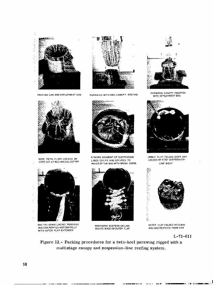
Packing Procedure
For each flight test, the reefed parawing was packed in a deployment bag designed to insure that the line stretch condition had occurred prior to the s tar t of wing inflation and that the canopy was adequately protected from the reefing rings and pyrotechnic line- cutters used to reef the suspension lines. A s illustrated in sketch (a), the deployment bag was divided into three sections: (1) a section for the canopy, (2) a section for the reefed portion of the suspension lines, and (3) a section for the remaining portion of the suspension lines. Photographs showing the packing procedure used during the flight tes ts a r e presented in figure 12. The canopy portion of the reefed parawing was pleated, folded, and then packed into the bottom section of the deployment bag and secured by folding down four rose-petal flaps and locking these flaps with a small-diameter cord. This cord w a s cut during deployment by a disk-type mechanical linecutter that was con- nected with a short length of cord to a reefing ring at the second-stage confluence point. The rather bulky reefed portion of the suspension lines was then coiled along the inside of
16

APPENDIX A - Concluded
Outer flap
Remaining portion
suspension lines
I Reefed portion of suspension lines I - Rose-petal
flaps
Sections of deployment bag
Sketch (a)
the bag and secured at several locations with break cords. folded down and locked by a bight of the suspension lines. line bights were made on the outer flap which was then folded down to complete the packing process. During the packing process, short lengths of small-diameter cord were used to connect the firing pins of the pyrotechnic linecutters to the inner walls of the deployment bag.
The inner flap was then The remaining suspension-
17

APPENDIX B
METHOD USED TO CALCULATE THEORETICAL DEPLOYMENT LOADS
The basic quantities known prior to the development of the multistage canopy and suspension-line reefing system were the initial deployment conditions, number of stages, and time intervals between the staging disreefs. The values of the lift-drag ratio and the resultant -force coefficient needed to prevent the peak deployment load from exceeding a 3g design limit during any stage of the deployment sequence were determined by trial and e r r o r by using the following theoretical method.
To simplify the analysis, the assumption was made that the parawing and payload were rigidly coupled during deployment and, therefore, that the time history of the deployment load could be determined by solving the two-degree-of -freedom point-mass equations of motion. (The equations a r e listed in ref. 5.) solve the equations of motion were the initial deployment conditions and the time histories of the lift-drag ratio and the resultant-force coefficient. also made that fo r each stage the lift-drag ratio and the resultant-force coefficient increased linearly from the time of stage disreef to full inflation, as illustrated in sketch (b).
The input quantities needed to
The assumption was
I Full inflation
Time
Sample time history of CR and L/D a t stage disreef
Sketch (b)
For this investigation i t was decided to develop a multistage reefing system com- posed of some form of canopy reefing during the initial stage of deployment followed by four stages of suspension-line reefing. For this analysis the time of nose disreef was set to occur midway between the third- and fourth-stage disreefs. The initial deploy- ment conditions for a 37.16 -m2 (400-ft2) twin-keel parawing scaled from those given in reference 2 for a 371.6-mz (4000-ft2) wing were (1) a deployment altitude of 762 m (2500 ft), (2) a deployment dynamic pressure of 2.73 kN/m2 (57.0 lb/ft2), and (3) a wing
18
I

APPENDIX B - Concluded
loading of 35.9 N/m2 (0.75 lb/ft2). force coefficient needed to prevent the peak deployment load from exceeding 4.00 kN (900 lb) for all the stages except the initial stage of deployment were obtained af ter sev- e ra l trial-and-error attempts with the computer -programed equations of motion. final values of the disreef time, inflation time, lift-drag ratio, and resultant-force coef - ficient for each stage a r e listed in table IV. An estimate of inflation time for each stage was based in part on the results presented in reference 2 and on unpublished data f rom several wind-tunnel and flight tests of other parawings reefed in similar ways. time histories of the lift-drag ratio and the resultant-force coefficient and the output time history of the deployment load resulting from the trial-and-error study a r e pre- sented in figure 13. The peak deployment load during the initial stage of deployment exceeded the design limit of 4.00 kN (900 lb) by approximately 0.67 kN (150 lb), but the peak deployment loads for the remaining stages were well below the design limit. Further study showed that a reduction in the value of the drag coefficient to 0.025 during the initial stage of deployment would reduce the peak deployment load to a value just below the design limit. The most practical way to obtain the needed reduction in the value of the drag coefficient would have been the addition of another stage of canopy reefing. It w a s believed, however, that an additional stage of canopy reefing would have only further complicated an already complex reefing system. It was decided, therefore, not to add another stage of canopy reefing.
The values of the lift-drag ratio and the resultant-
The
The input
19
II Ill Ill I l l Ill1 I I I I I I
APPENDIX C
DETAILS OF WIND-TUNNEL TESTS
Suspension-Line Rigging Tests
For the suspension-line rigging tests, the second, third, fourth, and gliding-stage line-segment lengths were equal to 0.037, 0.037, 0.073, and 0.50 t imes the keel length, respectively. The values of the line-segment lengths were chosen so that their sum was equal to the length of the wing-tip control line (LE11 suspension line). The line-segment lengths were proportioned to provide for larger increases in the inflated canopy shape during the later stages of deployment when the velocities were lower. It was assumed that the inlet a rea of the inflated canopy during the f i rs t stage of deployment was primarily dependent on the lengths of the leading- and trailing-edge suspension lines. Therefore, the f i rs t ser ies of tes ts performed were of a wing rigged with five variations. labeled A to E, of the first-stage inlet a r ea which were obtained by setting the lengths of the leading- and trailing-edge suspension lines (the lengths of TE8, LE11, and LE10 were not changed) equal to 0.022, 0.032, 0.040, 0.048, and 0.062 times the keel length, respectively. A ser ies of rigging tes ts were then made to determine the line lengths between the canopy and each stage confluence point needed to produce an inflated canopy shape with experi- mental values for the resultant-force coefficient and the lift-drag ratio as close as possi- ble to the design values. The suspension lines were held together a t the stage confluence point during the rigging tes ts by a line clamping device designed specifically for those tests. A photograph of this device is presented in figure 14.
The stage line lengths for the second to the fourth stage were determined consecu- tively by setting the initial line lengths for a given stage equal to the sum of the line- segment lengths for that and all preceding stages plus the line-payout lengths fo r all preceding stages except the stage immediately preceding the given stage. The line lengths were then adjusted with the canopy inflated at a low tunnel dynamic pressure until the lift-drag ratio and the resultant-force coefficient were as close as possible to the desired values for the given stage. Approximate aerodynamic forces were hand computed during the rigging phase of testing, and more exact values were machine computed after completion of the testing each day. The difference between the initial and the final se t of line lengths was the line-payout length for the stage immediately preceding the given stage. A record of the final line lengths for each stage was made to insure that the sum of the line-payout lengths of each line did not exceed the available length which was the total line length minus the sum of all stage line-segment lengths.
APPENDIXC - Concluded
Canopy Reefing Tests
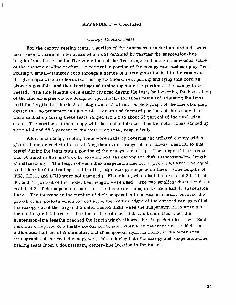
For the canopy reefing tests, a portion of the canopy was sacked up, and data were taken over a range of inlet areas which was obtained by varying the suspension-line lengths from those fo r the five variations of the first stage to those for the second stage of the suspension-line reefing. A particular portion of the canopy was sacked up by first routing a small-diameter cord through a series of safety pins attached to the canopy at the given spanwise o r chordwise reefing locations, next pulling and tying this cord as short as possible, and then bundling and taping together the portion of the canopy to be reefed. of the line clamping device designed specifically f o r those tes ts and adjusting the lines until the lengths for the desired stage were obtained. device is also presented in figure 14. The aft and forward portions of the canopy that were sacked up during these tests ranged from 0 to about 65 percent of the total wing area. were 41.4 and 58.6 percent of the total wing area, respectively.
The line lengths were easily changed during the tests by loosening the hose clamp
A photograph of the line clamping
The portions of the canopy with the center lobe and then the outer lobes sacked up
Additional canopy reefing tes ts were made by covering the inflated canopy with a given-diameter reefed disk and taking data over a range of inlet areas identical to that tested during the tests with a portion of the canopy sacked up. was obtained in this instance by varying both the canopy and disk suspension-line lengths simultaneously. The length of each disk suspension line for a given inlet area was equal to the length of the leading- and trailing-edge canopy suspension lines. TE8, LE11, and LE10 were not changed.) Five disks, which had diameters of 30, 40, 50, 60, and 70 percent of the model keel length, were used. each had 24 disk suspension lines, and the three remaining disks each had 48 suspension lines. growth of air pockets which formed along the leading edges of the covered canopy pulled the canopy out of the larger diameter reefed disks when the suspension lines were set for the larger inlet areas. suspension-line lengths reached the length which allowed the air pockets to grow. disk was composed of a highly porous parachute material in the inner area, which had a diameter half the disk diameter, and of nonporous nylon material in the outer area. Photographs of the reefed canopy were taken during both the canopy and suspension-line reefing tes ts from a downstream, center-line location in the tunnel.
The range of inlet areas
(The lengths of
The two smallest diameter disks
The increase in the number of disk suspension lines was necessary because the
The tunnel test of each disk was terminated when the Each
21

REFERENCES
1. Linhart, E. M.; and Buhler, W. C.: Wind Tunnel and Free Flight Investigation of All- Flexible Parawings a t Small Scale. Contract No. NAS 1-7467, Northrop Corp., June 1969. (Available as NASA CR-66879.)
2. Moeller, J. H.; Linhart, E. M.; Gran, W. M.; and Parson, L. T.: Free Flight Investi- gation of Large All-Flexible Parawings and Performance Comparison With Small Parawings - Final Report. Contract No. NAS 1-7467, Northrop Corp., Mar. 1970. (Available as NASA CR-66918.)
3. Amer. Power Jet Co.: Performance of and Design Criteria for Deployable Aerody- namic Decelerators. ASD-TR-61-579, U.S. Air Force, Dec. 1963. (Available from DDC as AD 429 921.)
4. Fournier, Paul G.; and Sleeman, William C., Jr.: Wind-Tunnel Studies of Effects of Construction Methods, Design Details, and Canopy Slots on the Aerodynamic Characteristics of Small-scale All-Flexible Parawings. NASA T N D-5974, 1970.
5. Gainer, Thomas G.: Investigation of Opening Characteristics of an All-Flexible Parawing. NASA TN D-5031, 1969.
22

.845
.746
1.065 1.065
TABLE I.- LINE LENGTHS O F A MULTISTAGE SUSPENSION-LINE REEFING SYSTEM FOR A TWIN-KEEL PARAWING
0.022 0.058 .058 .058 .062 .065 .a62 .058 .047 .037 0 0
0.032 0.048 .032 .048 .032 .048 .032 ,052 .032 .055 .032 .052 .032 .048 .032 .037 .029 .030 .022 0 0 0
0.040 0.040 .040 ,040 .040 .040 .040 .044 .040 .047 .040 ,044 .040 ,040 .040 .029 .037 ,022 .022 0 0 0
0.048 .048 .048 .048 .048 .048 ,048 .048 .044 .022
0
.048
.055
.059
.062
.066 ,070 .070 .070 .066 ,062 .055 .048
.048 ,048 ,048 .048 .048 .048 .044
0.032 0.062 0.018 0.037 0.058 0.037 0.140 0.073 0 0.037 0.096 0.073 0.044 0.500 .500 .500 500 .500 .500 .500 .500 .500 300 .500
.500 500 .500 .500 .500 .500 .500 .500 300 .500 .500 .500
.500
.500 500 .500 .500 .500 .500 .500
.500
.500
.500
LE1 LE2 LE3 LE4 LE5 LE6 LE7 LE8 LE9 LE10 LE11
K1 K2 K3 K4 K5 K6 K7 K8 K9 KlO K11 Kl2
TE1 TE2 TE 3 TE4 TE 5 TE6 TE7 TE8
TECO TECl
.022
.022
.022
.022
.022
.022
.022
.022
.022 0
.022
.029
.037
.037
.040
.044
.044
.044
.040
.037
.029
.022
.022
.022
.022
.022
.022
.022
.022
.022
.022
.022
.032
.032 ,036 ,039 ,036 .032 .021 ,015
0 0
.062
.062 ,062 .062 .062 .062 .062 .052 .022 0
.018
.018
.022
.025
.022
.018
.007
.007 0 0
.037
.037
.037
.037 ,037 .037 .037 .037 .037 .037
.051
.051
.040
.033
.029
.022
.026
.022
.037 0
.037 ,037 ,037 .037 .037 .037 .037 .037 ,037 ,037
,147 ,140 .132 .121 . lo6 .088 .066 .029
0 0
.073 0 .037
.073 0 .037 ,073 0 .037 .073 0 .037 .073 0 .037 .073 0 .037 .073 0 .037 .073 .018 .037 .073 .033 .037 .073 0 .037
. lo3
.096
.088
.077
.069
.066
.044
.029 0 0
.110
.117
.lo3
.lo3
.096
.092
.088
.084
.088
.095 ,099 .088
.165 206 2 2 8 2 0 6 .147 .lo3
.073 .044
.073 .044
.073 .044
.073 .044
.073 .037
.073 .022
.073 .022
.073 .018
.073 .033
.073 0
.073 .055
.073 .059
.073 .059
.073 .044
.073 .044
.073 .044
.073 .044
.073 .044
.073 .037
.073 .037
.073 .044 ,073 .029
.073 ,044
.073 .095
.073 .073
.073 .095
.073 ~ .095
.062 .032
.066 .039
.065 .043
.076 .046 .083 .050 .087 .054 .091 .054 .098 .054 .lo5 .050 .094 .046 .080 .039 .062 .032
,076 .032 .080 .032 ,066 .032 ,055 .032 .051 .032 .051 .032 .043 .029
0 .022
.052 .040 .044
.056 ,047 .048
.059 .051 ,051
.067 .054 .059
.073 .058 .065
.077 .062 .069
.081 ,062 .073
.088 .062 .080
.095 .058 .087 ,085 .054 .077 .070 .04? .062 .052 .040 .044
.066 ,040 .058 ,070 .040 .062 .056 ,040 ,048 .045 .040 .037 .041 ,040 .033 .041 ,040 .033 .036 .037 .028
.036 ,062
.040 .070 ,043 .073 .051 .077 .057 .081 .061 .084 .065 .084 .072 .084 .079 .081 .069 .077 .054 .070 ,036 .062
,050 .062 .054 .062 .040 .062 .029 .062 .025 .062 .025 .062 .021 .052
.022
.025
.029
.036
.042
.047
.051
.058
.064
.054
.039
.022
.037
.037
.037
.037
.037
.037
.037
.037
.037
.037
.037
.037
.077
.066
.073
.062
.059
.059
.055
.048
.037
.037
.033
.026
.037 ,037 .037 .037 .037 .037 ,037 .037 ,037 .037 .037 .037
.147 .073 .018
.147 .073 .029
.140 .073 .022
.147 ,073 0
.140 .073 0
.I36 .073 0
.132 .073 0
.128 .073 0
.125 .073 0
.132 .073 0
.143 .073 0 ,117 ,073 0
.044
.095
.073
.095
.095
.088
.059 1
.037
.037
.037
.037
.037
.037
.037
.037
.037
.037
.037
.037
.037
.037
.037
.037
.037
.037
.037
.036 ,037 .015 .037 .165 .073 ,040 .037 .015 ,037 .206 .073 .026 .037 .029 .037 2 2 8 .073 .015 .037 .040 .037 206 .073 .011 .037 .044 .037 .147 .073 .011 .037 .029 .037 .lo3 .073 .013 .037 .015 .037 .059 .073
.088
.059
.022
.088
.lo6
.140 -
.073
.073
.073
.073
.073
.073
.059
.026
.147
.143
.125
.022
.048
.048
.048 ~

N A
Test . . . . . . . . . . . . . . . . . . . . . . . . . . . 320 329 317 333 327 342
Description of canopy reefing . . . . . . . . . . . . . No canopy No canopy Aft 46.4% Aft 46.4% Forward 53.6% Center lobe reefing reefing of canopy of canopy of canopy sacked up
sackedup , sackedup sacked up
TABLE 11.- SUMMARY OF RESULTS FROM FLIGHT TESTS O F 37.16-m2 (400-ft2) TWIN-KEEL PARAWINGS RIGGED
WITH VARIOUS MULTISTAGE CANOPY AND SUSPENSION-LINE REEFING SYSTEMS
314 340
Outer lobes Canopy covered
diameter disk sacked up by 0.52k-
Modified fourth-stage suspension-line reefing . . . . Actualwing area, m2 (ft2) . . . . . . . . . . . . . . . 32.52 (350) 34.84 (375) 34.84 (375) 34.84 (375) 32.52 (350) 34.84 (375) 34.84 (375) 32.52 (350)
Payload. . . . . . . . . . . 1.05 (236) 1.07 (240) 1.07 (240) 1.07 (240) 1.05 (236) 1.07 (240) 1.07 (241) 1.03 (231) System weights, kN (Ib)
Total . . . . . . . . . . . . 1.17 (262) 1.25 (281) 1.25 (281) 1.25 (281) 1.17 (262) 1.25 (282) 1.25 (281) 1.17 (262)
No No No No No Yes No Yes
Suspension-line tes t strength, kN (lb) . . . . . . . . . 1.11 (250) 4.45 (1000) 4.45 (1000) 4.45 (1000) 1.11 (250) 4.45 (1000) 4.45 (1000) 1.11 (250)
Dynamic pressure at line stretch, W / m 2 (lb/ft2) . . 2.86 (59.7) 2.80 (58.5) 2.95 (61.7) 2.68 (56.0) 3.02 (63.0) 2.76 (51.7) 2.95 (61.6) 2.73 (57.0)
Time of
6.72 3.50 3.30 3.67 6.43 3.50 I canopy disreef . . . . . . . . . . . . -----._____ _ _ _ _ _ _ - - _ _ _
dep'G~ment Suspension-line event f rom disreef stage line stretch, sec, at -
I Fi r s t . . . . . . . . 6.40 6.50 13.71 6.55 6.56 6.52 13.58 6.20
I Second . . . . . . . 13.60 13.80 19.24 14.01 13.75 13.76 18.82 13.42
I Thi rd . . . . . . . . 19.04 18.87 27.62 18.93 19.10 18.95 26.79 18.16
Fourth . . . , . . . 25.79 25.89 34.40 25.94 26.18 25.33 33.52 24.60
Nose disreef . . . . . . . . . . . . . . 18.78 18.96 26.92 18.55 22.80 22.80 26.25 21.60
Line s t r e t c h . . . . . . . . . . . . . . 11.71 (2633) 8.02 (1803) 5.69 (1279) 7.97 (1792) 12.65 (2844) 10.80 (2428) 7.77 (1747) 9.68 (2177)
Initial opening. . . . . . . . . . . . . 4.88 (1096) 5.24 (1177) 3.91 (879) 4.51 (1014) 3.91 (880) 4.51 (1014) 5.47 (1230) 3.28 (738)
Peak deploy- Canopy disreef . . . . . . . . . . . . _ _ _ _ _ _ _ _ _ _ _ _ _ _ _ _ _ _ _ _ _ 2.18 (491) 2.56 (575) 2.61 (587) 2.82 (634) 1.79 (402) 2.52 (566) .- I Fi r s t . : : : : I : : 2.77 (622) 4.29 (965) 3.55 (799) 2.86 (642) 3.87 (869) 3.35 (754) 3.68 (828) 3.41 (767)
2.11 (475) 2.87 (645) 4.68 (1051) 2.86 (642) 3.21 (722) 2.74 (615) 3.17 (713) 2.43 (547)
disreef stage T h i r d . . . . . . . . 2.62 (588) 4.06 (912) 1.93 (434) 3.31 (744) 3.82 (858) 3.51 (790) 3.24 (729) 2.94 (662)
men1 ioaas, W (lb), for -
Suspension-line Second
I Fourth . . . . . . . 2.26 (509) 1.98 (446) 1.98 (445) 1.99 (448) 2.11 (474) 2.00 (450) 2.46 (552)- 2.43 (547)
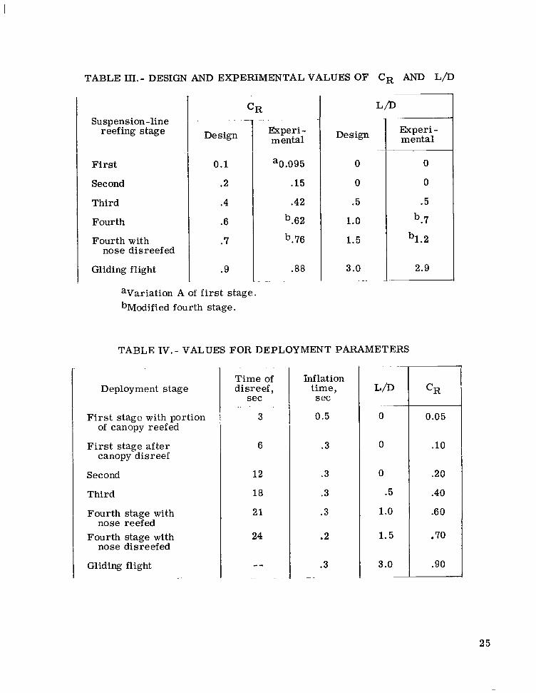
TABLE 111.- DESIGN AND EXPERIMENTAL VALUES OF CR AND L/D
Suspension-line reefing stage
First
Second
Third
Fourth
Fourth with nose disreefed
Gliding flight
CR . . -
De sign
0.1
.2
.4
.6
.7
.9
-. . .
Experi- mental
'0.095
.15
.42
b.62
b.76
.88 . -. .
Design
0
0
.5
1.0
1 .5
3.0 -.
Experi - mental
0
0
.5
b.7
b1.2
2.9
aVariation A of f i r s t stage. bModified fourth stage.
TABLE IV. - VALUES FOR DEPLOYMENT PARAMETERS
Deployment stage
F i r s t stage with portion of canopy reefed
First stage after canopy disreef
Second
Third
Fourth stage with nose reefed
Fourth stage with nose disreefed
Gliding flight
. . -
Time of disreef,
sec
3
6
12
18
21
24
-- ..
Inflation time, s ec
0.5
. 3
.3
.3
.3
.2
. 3 -~
. .
L/D
0
0
0
.5
1 .o
1.5
3.0 -
CR
0.05
.10
.20
.40
.60
.70
.90
25
/ -Vert ical s t ru t
CL
Bracing cable
Reefed parawing
---.- CD
.-
Figure 1.- Wind-tunnel test setup.
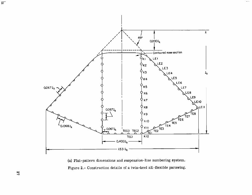
(a) Flat -pattern dimensions and suspension-line numbering system.
Figure 2. - Construction details of a twin-keel all-flexible parawing.
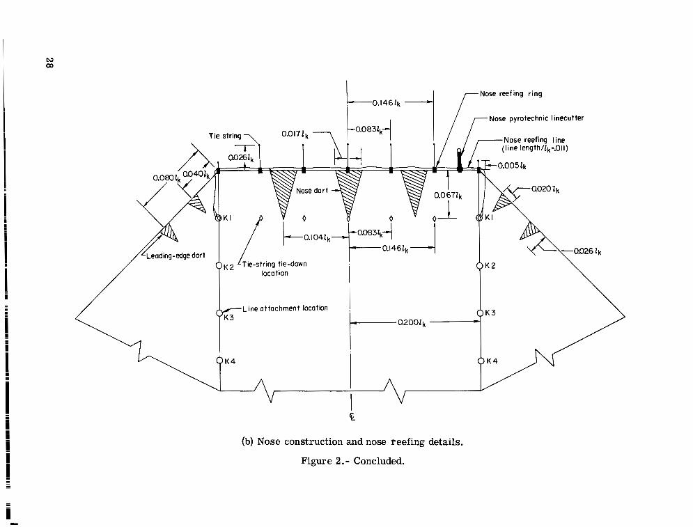
(b) Nose construction and nose f-eefing details.
Figure 2.- Concluded.

I T
S t a b i l i z e r d r o g u e deployed Dep loymen t p o r t i o n o f canopy s a c k e d u p L a u n c h
Second stage
T F i r s t s tage
T h i r d stage Fourth stage Fourth stage wi th nose d i s r e e f e d Gliding f l i g h t
(a) Ground-to-air view.
Figure 3. - Sketches showing deployment sequence of a twin-keel parawing rigged with a multistage canopy and suspension-line reefing system.
N CD
Second stage Port ion o f canopy sacked up F i rs t stage
Four th stage Four th stage w i t h nose disreefed G I iding f l igh t
Third stage
(b) Vehicle-to-air view.
Figure 3.4oncluded.
100.97cm I
(39.75 in.)
23.50 (9.25) 4- ;::% 49.53 .
I n s t r u m e n t compor tmcnt
1- 59.06 -_I (23.25)
L- 71 - 603 (a) Layout and photograph of instrumented payload.
Figure 4.- Details of instrumented payload used during flight tests.
31
1

1
2
3
4
5
6
7-8
RECORDING OSCILLERAPH 9 TIMING IMPULSE GENERATOR FOR RECORDING
PRESSURE TRANSDUCER
TIMER USED TO START CAMERA MOTOR AND
OSCILLERAPH
10 QUICK-MOUNT CAMERA MOUNT
F'IRE EXTERNAL ELECTRIC LINECVTTERS 11 CAMERA
MICRO-SWITCH USED TO p[pP ELECTRIC BLIP ON E C I L L E - RECORD AT START OF CAMERA FILM CAMERA MOTOR
TIMER ACTUATOR ROD
POWER SUPPLY FOR LOAD LINK
POWER SUPPLY FOR EXTERNAL ELECTRIC LINE-
12 INTEZ3RUPl'ER USED TO mlT TIMING PULSE ON
13 VOLTAGE REGULATOR
14 LOAD LINK
15-16 POWER SUPPLY FOR CAMERA AND RECORDER
c m m s 17 STATIC PORT
(b) Location diagram and list of instruments.
Figure 4. - Concluded.
32

I I 1 I C D E Second _- I
B I
A First-stage variations
Suspension- line reefing stage
.-Modified fourth stage
-
CR 1 ~ A
Fourth with Gliding nose disreefed f l ight
I Fourth
I Third
Su spe ns ion - I i ne re e f i ng stag e
(a) Aerodynamic characterist ics . Figure 5.- Test results and photographs from wind-tunnel tes t s of a twin-keel
parawing rigged with various stages of suspension-line reefing.
33
A I
B C First-stage variations-
D
T h i r d stage
E I Second stage
Four th stage Fourth stoge w i t h nose disreefed
Four th stage Fourth stage w i t h nosedisreefed
I- Modified fourth stoge I
L-71-604 (b) Photographs of canopy at various stages of suspension-line reefing.
Figure 5. - Concluded.
34
Reefed o r e o l T o 1 o l oreo, percent
0 64.6 0 5 5.9
46.4 36.0 248
? n 12.8 n 0
- 0 0
Chord wise reef ing loco1 ion
Troiling-edge reefing line P No socked-uporeo
I b
1 1 I I I I A B C D E Second
First-stage var io t ions
Suspension - line reefing stage
(a) Aerodynamic characteristics with various aft portions of canopy sacked up.
Figure 6.- Test results and photographs from wind-tunnel tes ts of a twin-keel parawing rigged with various canopy reefing methods.
35
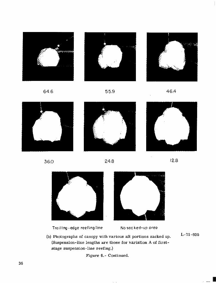
64.6 5 5.9 46.4
3 6.0 24.8 12.8
Trailing-edge reefing line No sac ked-up area
L-71-605 (b) Photographs of canopy with various aft portions sacked up. (Suspension-line lengths a r e those for variation A of first- stage suspension- line reefing.)
Figure 6. - Continued.
36

Reefed area /Total area, Chordwise ree l ing Dercenl location 60.4 53.6 44.1 35.4 27.4 20.3 14.0 8.5 0
K9 - LEE KE - LE7 K7-LE6 K6- LE5 K5- LE4 K 4 - LE3 K3- LE2 K2- LEI No socked-upareo P
I ._ 1- .- A B C D E Second I
First-s toge var io tions
Suspension-line reefing stage
(c) Aerodynamic characteristics with various forward portions of canopy sacked up.
Figure 6. - Continued.
37
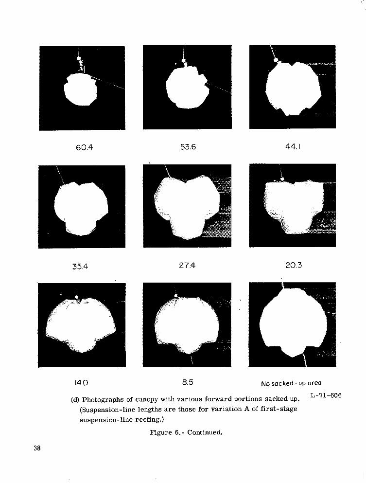
60.4 53.6 44.1
35.4
14.0
27.4
8.5
20.3
No sac ked - up area
L- 71 -606 (d) Photographs of canopy with various forward portions sacked up. (Suspension-line lengths a r e those for variation A of first-stage suspension- line reefing.)
Figure 6. - Continued.
38

.I5
.I4
.I2
. I I
.IO
.09
CD .08-
.07
.06
.05
.04
.03
.02
.01
0 Outer lobes socked up
0 C e n t e r lobe sacked up
,161-
-
-
.13-
-
-
-
-
-
-
-
-
-
-
-
0-
0
n s 0 r\ 0
A 0 C Q E First-stage variations
Suspension-line reefing stage
(e) Aerodynamic characteristics with outer lobes sacked up and with center lobe sacked up.
Figure 6.- Continued.
39

B E
@ ) O u t e r lobes sacked up
Second
E
t. '. p r + e r lobesocked u p
Second
L- 7 1 -60 7
(f) Photographs of canopy with outer lobes sacked up and with center lobe sacked up. stage indicated under each photograph.)
(Suspension-line reefing
Figure 6.- Continued,
40

Disk d iometer l lk
0 .3 0 .4 0 .5 D .6 b .7 0 Nodisk
b
1- C D E Second
I B
I A
Firs t-s tage variations
Suspension-line reefing stage
(g) Aerodynamic characteristics with canopy covered by various-diameter reefed disks.
Figure 6.- Continued.
41
a 5 2k Side view of 3 2 k-diameter disk
.6 l k Disk diameter =.7E k
L-71-608 (h) Photographs of canopy covered by various-diameter reefed disks.
(Suspension-line lengths are those for variation A of first-stage suspension-line reefing.)
Figure 6. - Concluded.
42
A w
t,sec
(a) Test 320 - no canopy reefing.
Figure 7.- Time histories of deployment loads from flight tests of twin-keel parawings rigged with various canopy and suspension-line reefing methods.

A i A
t,sec
t,sec
(b) Test 329 - no canopy reefing.
Figure 7.- Continued.
--
- I 0 I 2 3 4 5 6 7 8 9 IO I I 12 13 14 15 16 17 18 19 t, sec
--__ .I 2 I y F - - - . . . . . . . . . -. -____
. . . . . . .
. . . . . .
. . .
~ - ~~ . ~ ~ _ _ ~ ~- . . . . . . . . . . . . . . . . . . . . .
19 20 21 22 23 24 25 26 27 28 29 30 31 32 33 34 35 36 37 38 39 t , sec
(c) Test 317 - aft 46.4 percent of canopy sackedup.
Figure 7. - Continued.
CF
D e s i g n l imi
Der
(d) Test 333 - aft 46.4 percent of canopy sacked up.
Figure 7.- Continued.
-I 0 I 2 3 4 5 6 7 8 9 1 0 1 1 1 2 1 3 1 4 1 5 t,sec
_______-
I
15 16 17 18 19 20 21 22 23 24 25 26 27 28 29 30 31 t ,sec
(e) Test 327 - forward 53.6 percent of canopy sacked up.
Figure 7.- Continued.
- . . . . .. . . -. -. . . . . . . . . . . .
-I 0 I 2 3 4 5 6 7 8 9 IO I I 12 13 1 4 1 5 t,sec
15 16 17 18 19 20 21 22 23 24 25 26 27 28 29 30 31 t,sec
(f) Test 342 - center lobe sacked up; modified fourth-stage suspension-line reefing.
Figure 7.- Continued.

CF
Deriqn l imi i
- 1 0 I 2 3 4 5 6 7 8 9 IO I I 12 13 14 15 16 17 18 t,sec
- . . . ! . . . . . .~ . . . . . . . . . . . . . . . . . . . . - . . .
I ' 1 . ; ; +-. j . ~ ___ , .
. . ~ . . - .12. : i - I . * . . . . , .
"18 19 20 21 22 23 24 25 26 27 28 29 30 31 32 33 34 35 36 37 t,sec
(g) Test 314 - outer lobes sacked up.
Figure 7.- Continued.
CF
Ocrtqn l i m i l
CF
Design limi
t , sec
(h) Test 340 - canopy covered by 0.5Zk-diameter reefed disk; modified fourth-stage suspension-line reefing. .
Figure 7. - Concluded.
Canopy attachment point
P y ro t ec hn ic linecut ler
Sleeve for storing
Gliding-stage line segment
Unreefed condition Reefed condition
(a) Division of typical suspension line.
Figure 8. - Details of suspension-line reefing.
51
+-,Firing pin
G h inese finger line joint
\ \\
Pyrotechnic I ine cutter I
-Reefing line
x -
L P'
Reinforcement bushing
interlocking line loops
Line reefing ring P *
i
x,
' Suspension line-
(I'
Dual-hole ' reefing ring
L- 7 1 - 60 9 (b) Reefing hardware.
Figure 8. - Continued.
52

LEI I
Pyrotechnic x- I i necu t ter
Re i n forcement bus hi ng
( c ) Order of suspension lines on reefing line.
Figure 8.- Concluded.
53

L-71-610 Figure 9.- Photograph of a twin-keel parawing rigged with
four stages of suspension-line reefing.
54
I 11111 I 1

(a) Tests 317 and 333 - aft 46.4 percent of canopy sacked up.
(b) Test 327 - forward 53.6 percent of canopy sacked up.
Figure 10.- Reefing details of canopy reefing methods flight tested. (Top view of wing shown.)
55
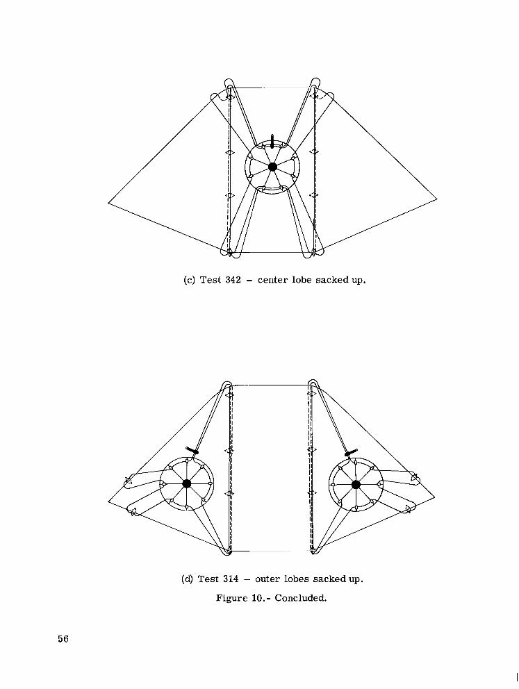
(c) Test 342 - center lobe sackedup.
(d) Test 314 - outer lobes sackedup.
Figure 10.- Concluded.
56
Line reefing ring,
76.3.g/m2 (2.250z/yd2) nylon rip-stop material / r
1
2.54cm (I-inch)meshcotton net
f r
Figure 11.- Construction details of 0.5lk-diameter disk.
57
PARAWING CANOPY INSERTED INTO DEPLOYMENT BAG PACKING CAN AND DEPLOYMENT BAG PARAWING WITH DISK CANOPY REEFING
STAGING SEGMENT OF SUSPENSION INNER FLAP FOLDED OVER AND LINES COILED AND SECURED TO INSIDEOF THE BAG WITH BREAK CORDS
LOCKED BY FIRST SUSPENSION- ROSE-PETAL FLAPS LOCKED BY CORD CUT BY MECHANICAL CUTTER "
LINE BIGHT
OUTER FLAP FOLDED INTO BAG AND BAG REMOVED FROM CAN
REMAINING SUSPENSION-LINE BIGHTS MADE ON OUTER FLAP
BAG TIE-DOWN LACING REMOVED AND CAN ROTATED HORIZONTALLY WITH OUTER FLAP EXTENDED
L-71-611 Figure 12.- Packing procedures for a twin-keel parawing rigged with a
multistage canopy and suspension-line reefing system.
58
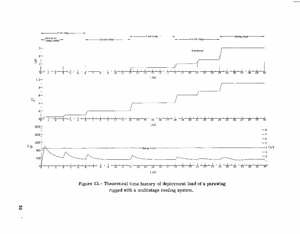
- First stoge -
- I
-Third stoge - - Gliding stoge c
Portion of -Second stoge- -Fourth stoge -canopy reefed--
- 2 - I
/-
- 3
t ,sec
Figure 13.- Theoretical time history of deployment load of a parawing rigged with a multistage reefing system.

(a) Hardware for suspension-line reefing tests.
L-71-612 (b) Hardware for canopy
reefing tests.
Figure 14.- Photograph of hardware used for wind-tunnel tests of canopy and suspension-line reefing methods.

I
A motion-picture film supplement L-1086 is available on loan. Requests will be
The film (16 mm, 3 min, color, silent) shows the deployment of a 37.16-mz (400-ft2) twin-keel parawing rigged with a multistage reefing system composed of four stages of suspension-line reefing with a forward portion of the canopy sacked up during the first stage.
filled in the order received. You will be notified of the approximate date scheduled.
Both ground-to-air and vehicle-to-air views are presented.
Film supplement L-1086 is available on request to:
NASA Langley Research Center Att: Hampton, Va. 23365
Photographic Branch, Mail Stop 171
I
I TN D-6306. Please send, on loan, copy of film supplement L-1086 to
I
I Name of organization I
~ - - .~ - _ _ I Street number
I City and State
I
I ~ _ _ ~- __
Zip code
~ I Attention: Mr. -

NASA Langley Research Center Att: Photographic Branch, Mail Stop 171 I
Hampton, Va. 23365 I
NATIONAL AERONAUTICS AND SPACE ADMINISTRA? ION
WASHINGTON, D. C. 20546
OFFICIAL BUSINESS PENALTY FOR PRIVATE USE $300
FIRST CLASS MAIL
POSTAGE AND FEES PAID NATIONAL AERONAUTICS ANI
SPACE ADMINISTRATION
OOX 001 CL U 01 710723 S00903DS D E P T OF THE A I R FORCE WEAPONS LABORATORY /WLOL/
K I R T L A N D AFB NM 87117 ATTN: E LOU BOWMAN, CHIEF TECH L I B R A R Y
POSTMASTER: If Undeliverable (Section 158 Postal Manual ) Do Nor Return
“The aeronautical and space activities of the United States shall be conducted so as to contribute . . . to the expansion of human knowl- edge of phenoniena in the atniosphere and space. The Administration shall provide for the widest prrrcticable and appropriate disseminatioiz of inforiiiation concerning its activities and the restilts thereof.”
-NATIONAL AERONAUTICS AND SPACE ACT OF 1958
NASA SCIENTIFIC AND TECHNICAL PUI3LICATIONS
TECHNICAL REPORTS: Scientific and technical information considered important, complete, and a lasting contribution to existing knowledge.
TECHNICAL NOTES: Information less broad in scope but nevertheless of importance as a contribution to existing knowledge.
TECHNICAL MEMORANDUMS: Information receiving limited distribution because of preliminary data, security classifica- tion, or other reasons.
TECHNICAL TRANSLATIONS: Information published in a foreign language considered to merit NASA distribution in English.
SPECIAL PUBLICATIONS: Information derived from or of value to NASA activities. Publications include conference proceedings, monographs, data compilations, handbooks, sourcebooks, and special bibliographies.
TECHNOLOGY UTILIZATION PUBLICATIONS: Information on technology used by NASA that may be of particular interest in commercial and other non-aerospace applications. Publications include Tech Briefs, Technology Utilization Reports and Technology Surveys.
CONTRACTOR REPORTS: Scientific and technical information generated under a NASA contract or grant and considered an important contribution to existing knowledge.
Details on the availability of ihese publications may be obtained from:
SCIENTIFIC AND TECHNICAL INFORMATION OFFICE
NATIONAL AERONAUTICS AND SPACE ADMINISTRATION Washington, D.C. PO546
1 ..