NASA TECHNICAL NASA MEMORANDUM · Saturn IB SA-203 Altitude as a Function of Range for a 100-N.M....
132
NASA TECHNICAL MEMORANDUM , NASA XbLX-53158 : NoT~M~.. !1. 1964 SATURN IB LIQUID HYDROGEN ORBITAL EXPERl MENT DEFl NlTlON . by ADVANCED STUDIES OFFICE Propulsion and Vehicle Engineering Laboratory OTS PRICE NASA George C. Marshall S’uce Fght Center, Hmtsuille, Alabama XEROX M ICRO FI LM https://ntrs.nasa.gov/search.jsp?R=19650000625 2018-07-14T09:58:50+00:00Z
-
Upload
truongcong -
Category
Documents
-
view
213 -
download
0
Transcript of NASA TECHNICAL NASA MEMORANDUM · Saturn IB SA-203 Altitude as a Function of Range for a 100-N.M....

NASA TECHNICAL MEMORANDUM
,
NASA XbLX-53158 :
N o T ~ M ~ . . !1. 1964
SATURN I B LIQUID HYDROGEN ORBITAL EXPERl MENT DEFl NlTlON .
by ADVANCED STUDIES OFFICE Propulsion and Vehicle Engineering Laboratory
OTS PRICE
NASA
George C. Marshall S’uce F g h t Center, Hmtsuille, Alabama
XEROX
M ICRO FI LM
https://ntrs.nasa.gov/search.jsp?R=19650000625 2018-07-14T09:58:50+00:00Z
TECHNICAL MEMORANDUM X-53158
I ' SATURN IB LIQUID HYDROGEN ORBITAL EXPERIMENT DEFINITION
Compiled By
Advanced Studies Office
George C. Marshall Space Flight Center
Huntsville , Alabama
ABSTRACT
A Liquid Hydrogen Orbital Experiment i s defined, using Saturn IB iaunch vehicle SA-203, which will demonstrate the adequacy of the S-IVB/V continuous vent and propellant settling system prior to a Saturn V launch. propellant behaviour under weightless environment will be significantly advanced by this observation of transient effects on liquid hydrogen through two television cameras mounted on the manhole cover of the S-IVB stage LH2 tank.
The state -of-the -ar t knowledge of cryogenic
The experiment justification, objectives, and S-IVB stage instrumentation a r e presented in detail.
The liquid hydrogen experiment was proposed and defined by the Propulsion Division of Propulsion and Vehicle Engineering Laboratory. This report was compiled for R&D Operations with the assistance of Aero -A s t r odynamic s Labor a tory, As tfionic s Labor at or y, and Quality and Reliability Assurance Laboratory and complements NASA TM X-53 159, "Saturn IB Liquid Hydrogen Experiment Preliminary Lau Design Definition.
NATIONAL AERONAUTICS AND SPACE ADMINISTRATION

AXO.LVXOBV? 3 N I l 3 3 3 N I 3 N 3 3 1 3 I H 3 A a N V N O I S T n d O X d
X 3 L N 3 3 LH3ITJ 3 3 V d S T ? V H S ~ ~ ' 3 3 3 X O 3 3 - V S V N

TABLE OF CONTENTS
Page
. . . . . . . . . . . . . . . . . . . . . . . . . . . . . . . . . . . . SUMMARY 1
SE C TION I. INTRODUCTION 3
A. GENERAL 3
B. CONTINUOUS VENT AND LIQUID SETTLING 3
C. FLUID MECHANICS AND HEAT TRANSFER 3
. . . . . . . . . . . . . . . . . . . . . . . . . . . . . . . . . . . . . . . . . . . . . . . . . . . . .
. . . . . . . . . . . . .
. . . . . . . . . . . . . SECTION 11. EXPERIMENT JUSTIFICATION 5
A. BACKGROUND ............................ 5
SEQUENCE 5
C. POTENTIAL LOW-GRAVITY PROBLEMS. 7
B. S-IVB VENTING SYSTEM AND OPERATING . . . . . . . . . . . . . . . . . . . . . . . . . . . . .
. . . . . . . . . . . . D. LIMITATIONS OF PRESENT TEST FACILITIES. 8
9 E. VALUE OF PROPOSED ORBITAL EXPERIMENT . . . . SECTION III. EXPERIMENT DESCRIPTION. . . . . . . . . . . . . . 10
A. GENERAL .............................. 10
B. EXPERIMENT CHARACTERISTICS . . . . . . . . . . . . . 10
C. TELEVISION SYSTEM. ..................... 10
11
12
F. DATA REDUCTION. ....................... 12
D. INSTRUMENTATION ....................... E. DATA RE TRIEVAL ........................
. . . . . . . . . . . . . . SECTION IV. EXPERIMENT OBJECTIVES 13
A. SATURN V STUDIES ....................... 13
B. TEST OBJECTIVES ....................... 13
SECTION V. MISSION PROFILE ..................... 15
SEQUENCE OF ORBITAL EVENTS 15 . . . . . . . . . . . . .
- -. 111

TABLE OF CONTENTS (Continued)
Page
SECTION VI . NOSE CONE CONFIGURATION . . . . . . . . . . . . . . . . . . . . . . . . . . . A CONFIGURATION SELECTION
B . DESIGN . . . . . . . . . . . . . . . . . . . . . . . . . . . . . . C . INSTRUMENTATION . . . . . . . . . . . . . . . . . . . . . .
SECTION VII . VEHICLE PERFORMANCE . . . . . . . . . . . . . A . PROPELLANT LOADING . . . . . . . . . . . . . . . . . . . B . TRAJECTORY DESIGN . . . . . . . . . . . . . . . . . . . . C . DYNAMIC RESPONSE STUDY FOR STRENGTH
ANALYSIS . . . . . . . . . . . . . . . . . . . . . . . . . . . . . D . VEHICLE STABILITY . . . . . . . . . . . . . . . . . . . . . E . LOX TANK SLOSH BAFFLE . . . . . . . . . . . . . . . . . F . PROPELLANT UTILIZATION SYSTEM . . . . . . . . . G . REQUIREMENTS FOR A AV CUT-OFF-SYSTEM . . . H . S-IVB STAGE SEPARATION DYNAMICS . . . . . . . . . I . ULLAGE THRUST SYSTEM . . . . . . . . . . . . . . . . . J . CONTINUOUS VENT THRUST LEVEL . . . . . . . . . . K . AUXILIARY PROPULSION SYSTEM . . . . . . . . . . . . L . HYDROGEN TANK REPRESSURIZATION SYSTEM . .
SECTION VI11 . S-IVB VENTING SYSTEM . . . . . . . . . . . . . . A . CONTINUOUS VENTING SYSTEM . . . . . . . . . . . . . B . REQUIREMENTS AND PROBLEMS OF THE
CONTINUOUS VENT SYSTEM . . . . . . . . . . . . . . . . SECTION IX . EXPERIMENT INSTRUMENTATION . . . . . . . .
A . PURPOSE . . . . . . . . . . . . . . . . . . . . . . . . . . . . . B . TELEVISION REQUIREMENTS . . . . . . . . . . . . . . . C.’ IMPLEMENTATION O F TELEVISION SYSTEM . . . .
19
19
19
19
23
23
23
23
23
25
25
26
2 6
26
27
27
28
29
29
29
34
3 4
3 4
39
iv

P
c
TABLE OF CONTENTS (Continued)
Page
D . EXPERIMENT INSTRUMENTATION . . . . . . . . . . . . . 42
E . TELEMETRY SYSTEM ..................... 53
F . HYDROGEN EXPERIMENT . GENERAL COMMENTS . 59
SECTION X . S-IVB STAGE MODIFICATIONS . . . . . . . . . . . . . 60
A . PROGRAM PLAN ......................... 60
B . MODIFICATION INSTALLATIONS . . . . . . . . . . . . . . 72
C . STRUCTURAL MODIFICATIONS . . . . . . . . . . . . . . . D . LOX BAFFLE MODIFICATION . . . . . . . . . . . . . . . . E . LH2 TANK INSTRUMENTATION SUPPORT STRUCTURE
F . MISCELLANEOUS STRUCTURAL MODIFICATIONS . . G . POWER SYSTEM MODIFICATIONS . . . . . . . . . . . . . H . NETWORKS ............................. I . CAMERA AND EQUIPMENT . . . . . . . . . . . . . . . . . . J . PROPULSION SUBSYSTEM MODIFICATION . . . . . . . K . VENT SYSTEM MODIFICATION . . . . . . . . . . . . . . . L . SEQUENCER MODIFICATIONS . . . . . . . . . . . . . . . . M . WEIGHTS . . . . . . . . . . . . . . . . . . . . . . . . . . . . . . N . MANHOLE COVER ........................ 0 . INSTRUMENTATION FEED THROUGH . . . . . . . . . . . P . SCHEDULE ............................. Q . UNRESOLVED PROBLEMS . . . . . . . . . . . . . . . . . .
73
74
74
76
79
80
80
80
84
84
85
86
86
8;
86
SECTION XI . DOCUMENTATION .................... 89
REQUIREMENTS ......................... 89
V

TABLE OF CONTENTS (Continued)
Page
SECTION XI1 . TESTING . . . . . . . . . . . . . . . . . . . . . . . . . . 9 1
A . TESTING REQUIREMENTS . . . . . . . . . . . . . . . . . . 91
B . PROPULSION ACCEPTANCE TESTING . . . . . . . . . . 92
C . FINAL INSTALLATION AND CHECKOUT . . . . . . . . . 93
D . STATIC FIRING . . . . . . . . . . . . . . . . . . . . . . . . . . 93
SECTION XI11 . DATA RETRIEVAL . . . . . . . . . . . . . . . . . . . 94
A . ACQUISITION . . . . . . . . . . . . . . . . . . . . . . . . . . . 94
B . REDUCTION . . . . . . . . . . . . . . . . . . . . . . . . . . . . 94
C . ANALYSIS . . . . . . . . . . . . . . . . . . . . . . . . . . . . . . 94
D . DATA MEASUREMENTS . . . . . . . . . . . . . . . . . . . . 94
SECTION XIV . RELIABILITY AND QUALITY ASSURANCE . . . 97
A . GENERAL . . . . . . . . . . . . . . . . . . . . . . . . . . . . . . . 97
B . RELIABILITY . . . . . . . . . . . . . . . . . . . . . . . . . . . 97
C . QUALITY CONTROL . . . . . . . . . . . . . . . . . . . . . . . 97
D . DOCUMENTATION . . . . . . . . . . . . . . . . . . . . . . . . 9 7
E . DAC PERFORMANCE . . . . . . . . . . . . . . . . . . . . . . 98
F . PRESSURE LEAK CHECK . . . . . . . . . . . . . . . . . . . 99
G . ELECTRICAL-OPTICAL FUNCTIONAL TEST . . . . . . 99
H . RECEIVING INSPECTION . . . . . . . . . . . . . . . . . . . 99
SECTION XV . GROUND SUPPORT EQUIPMENT . . . . . . . . . . 100
A . ELECTRICAL . . . . . . . . . . . . . . . . . . . . . . . . . . . 100
B . MECHANICAL . . . . . . . . . . . . . . . . . . . . . . . . . . . 102
C . GOVERNMENT FURNISHED PROPERTY . . . . . . . . . 102
vi

TABLE OF CONTENTS (Concluded)
Page
APPENDIX A. SATURN IB (SA-203) PERFORMANCE CAPABILITY ...................... 104
APPENDIX B. DRAG FORCE, ORBITAL LIFETIME, AND GROUND COMMUNICATIONS VISIBILITY FOR SATURN IB LIQUID HYDROGEN ORBITAL EXPERIMENT ..................... 113
vii

LIST O F ILLUSTRATIONS
Figure
6-1
6 -2
7-1
8-1
8 -2
8 -3 8 -4
9-1
9 -2
9-3
9 -4
9 -5
9-6
9 -7
9-8
9 -9
9-10
9-11
9-12
Title Page
Configuration 1 . . . . . . . . . . . . . . . . . . . . . . . . . . . . 19
Configuration 2 . . . . . . . . . . . . . . . . . . . . . . . . . . . 21
Saturn IB SA-203 Altitude as a Function of Range for a 100-N.M. Circular Orbit . . . . . . . . . . . . . . . . . . . . . 24
Ullage Thruster Oxidizer Tank . . . . . . . . . . . . . . . . . 30
Fuel Tank Vent System . . . . . . . . . . . . . . . . . . . . . . Schematic. LOz and LH2 Ullage Thrusting . . . . . . . . . . Continuous Vent System Configurations . . . . . . . . . . . 33
31 32
Airborne Television Systems Block Diagram . . . . . . . . 40
TV Camera and Light Installation . . . . . . . . . . . . . . . 41
Ground Television Stations Block Diagram . . . . . . . . . 43
Hydrogen Tank Instrumentation . . . . . . . . . . . . . . . . . 48
Additional Instrumentation Required for Saturn IB Orbital Hydrogen Experiment . . . . . . . . . . . . . . . . . . 49
Additional Instrumentation Required for Saturn IB Orbital Hydrogen Experiment . . . . . . . . . . . . . . . . . . 50
Additional Instrumentation Required for Saturn IB Orbital Hydrogen Experiment . . . . . . . . . . . . . . . . . . 51
Additional Instrumentation Required for Saturn IB Orbital Hydrogen Experiment . . . . . . . . . . . . . . . . . . 52
"Checkout Only" Multiplexer . . . . . . . . . . . . . . . . . . 54
PAM Link No . 1 . Located Forward . . . . . . . . . . . . . 55
PAM Link No . 2 . Located Aft . . . . . . . . . . . . . . . . . 56
PAM Line No . 3 . Located Aft . . . . . . . . . . . . . . . . . 57 ...
V l l l

LIST OF ILLUSTRATIONS (Continued)
Figure Title Page
9-13 Module Space and Decoder Lines Available on Signal 58 Conditioning Racks . . . . . . . . . . . . . . . . . . . . . . . .
10-1 Modifications to S-IVB for Liquid Hydrogen Orbital Experiment 61 . . . . . . . . . . . . . . . . . . . . . . . . . . . . .
10-2 Modified Baffle for Liquid Hydrogen Orbital Experiment . . . . . . . . . . . . . . . . . . . . . . . . . . . . . 75
10 -3 Liquid Hydrogen Orbital Experiment Instrumentation . . . . . . . . . . . . . . . . . . . . . . . . . . . . . . . 77 Support.
10-4 Liquid Hydrogen Tank TV Camera Manhole In stallat ion . . . . . . . . . . . . . . . . . . . . . . . . . . . . . 81
10-5 Manhole Cover Assembly, Top View . . . . . . . . . . . . 82
10 -6 Liquid Hydrogen Orbital Experiment S-IVB Schedule . 87
11-1 Liquid Hydrogen Orbital Experiment Documentation Responsibility . . . . . . . . . . . . . . . . . . . . . . . . . . . 90
1 Saturn IB SA-203 Cutoff Weight in Orbit as a Function of Second stage Lift-off Weight for a 100 Nautical Mile Circular Orbit . . . . . . . . . . . . . . . . . . . . . . . 106
2 Saturn IB SA-203 Nominal L i p i d Hydrogen in Orbit as a Function of S-IVB Jettison Weight for a 100-Nautical Mile Circular Orbit . . . . . . . . . . . . . . . . . . . . . . . 107
3 Schematic Hydrogen Tank . . . . . . . . . . . . . . . . . . . 108
4 Saturn IB SA-203 Altitude as a Function of Range for a 100-Nautical Mile Circular Orbit . . . . . . . . . . . . . 109
5 Saturn IB SA-203 Nominal Liquid Hydrogen in Orbit as a Function of Upper Mixture Ratio Burn Time for
110 a Step Mixture Ratio Program of 5.4/4. 7 . . . . . . . . .
ix

Figure
1
2
LIST O F ILLUSTRATIONS (Concluded)
Title Page
Orbiting Configuration. . . . . . . . . . . . . . . . . . . . . . Orbital Ground Projection 185 km Circular Orbit. . . .
114
116
X

LIST O F TABLES
Table
2 - 1
5 - 1
5 -2
9 -1
9 -2
9 -3
10-1
1
2
3
1
Title Page
Limitations of Low Gravity Testing Facil i t ies. . . . . . . 6
Liquid Hydrogen Orbital Experiment Sequence of Events . . . . . . . . . . . . . . . . . . . . . . . . . . . . . . . . . 16
Factors Influencing Experiment Lifetime . . . . . . . . . . 18
System Parameters At Given Frequencies for Liquid Hydrogen Orbital Experiment . . . . . . . . . . . . . . . . . . 36
Time Over High Rate Stations. . . . . . . . . . . . . . . . . . . 38
Prior i ty of Additional Installed Instrumentation. . . . . . 44
S-IVB Weight Breakdown. . . . . . . . . . . . . . . . . . . . . . 85
S-IVB Jettison Weight Definition. . . . . . . . . . . . . . . . 105
Saturn IB T w o Stage to 100-N. M.Circular Orbit for (SA-203) LH2 Experiment. . . . . . . . . . . . . . . . . . . . . 11 1
Saturn IB T w o Stage to 100-N.M. Circular Orbit f o r (SA-203) LH2 Experiment. . . . . . . . . . . . . . . . . . . . . 112
Ground Communications Time Line . . . . . . . . . . . . . . 117
xi

TECHNICAL MEMORANDUM X-53158
* SATURN IB LIQUID HYDROGEN ORBITAL EXPERIMENT DEFINITION
SUMMARY t
Data in the a r e a s of fluid mechanics of cryogenic propellants and heat t ransfer in an'orbital environment a r e almost non-existant. orbital experiment is necessary to provide the data and a s su re a reliability for future manned efforts a t the level required by NASA. [The Liquid Hydrogen Orbital Experiment is planned to provide data on continuous orbital vent and settling a s well as stage res ta r t . The experiment will be of equal value whether it substantiates existing design assumptions or provides data indicating the need for corrective r e -design.
An
'The experiment wi l l be conducted in a 100-N. M. c i rcular orbit. The sequence of events for the experiment will be initiated by an on-board recorder o r by ground commands. mounted in the manhole cover of the modified S-IVB stage of the Saturn IB launch vehicle, SA-203. interface during coast, orbit insertion, orbital maneuvers, and re- circulation and thrust chamber chilldown prior to r e -ignition. \ Auxiliary instrumentation will transmit data on pressure , temperature, acceleration, etc. and possibly for as long as four orbits. dictated the use of an aerodynamic nose cone envelope. be fabricated by MSFC. construction and will have a coat of ablative material on its exterior surface and will weigh about 3500 pounds. will provide data or acceleration, acoustics, pressure, and temperature.
T w o television cameras wi l l be
These w i l l observe the liquid/gas propellant
Data will be received for a minimum of three orbits Control and payload considerations
The nose cone wi l l It wi l l be'of skin and skin-and-stringer type
Nose cone instrumentation
Propellant loading will be controlled by the S-IVB propellant utilization system. and 6 5 per cent LOX it is estimated that a payload of approximately 18,000 pounds of LH2 will be placed in orbit. design t ra jector ies will employ trajectory shaping to ensure s t ructural integrities of the vehicle.
With the planned loading levels of 100 per cent LH2
The construction of the
Stage flight will be accomplished with the P U system in the open This requirement is imposed by the excessive tank mixture
Control considerations loop mode. ra t io inbalance caused by the hvdrogen Davload.

dictated that the stage be shutdown by guidance on the attainment of the nominal Saturn V parking orbit. The desirability of eliminating residual LOX was overridden by the inability to cancel out the velocity increment the burnout would entail.
Hydrogen vented overboard through a continuous vent thrust system will be used to provide a positive axial acceleration of approximately 2 x The exact configuration of the continuous venting system is still under study. available and alternative systems for cancelling out the required fraction of the thrust a r e under consideration.
g on the stage during orbital coast to ensure propellant settling.
More than sufficient thrust to provide the required g load is
The thrust of the S-IVB 70-pound ullage rockets will be simulated by ducting residual LOX ullage gas overboard two axial ly directed nozzles. An increase in auxiliary propulsion system requirements will necessitate some system modifications. repressurization system will be simulated during this experiment.
Also, the Saturn V/S-IVB LH2 tank
Sufficient airborne telemetry channel capacity exists to transmitt Existing ground facilities a r e capable of handling the
The 30-foot dish antenna required the acquired data. transmitted data with two exceptions. by the high-rate TV camera is scheduled to be ready for use by the SA-203 launch date. video recorder t o the selected high-rate receiving stations.
Also, MSFC will be required to provide a special wide-band
The high-rate stations will make immediate film copies of the high-rate TV data. be used as backup. types to MSFC for analysis.
If the high-rate system should fail, low-rate data wi l l DAC wil l provide linearized data f rom the telemetry
Documentation, testing, and reliability practices will conform to NASA, MSFC, and Saturn V standards.
2

SECTION I. INTRODUCTION
A. GENERAL
The success of the Saturn V program requires many state- of -the -art advance s. cryogenic propellant in a low gravity field and heat t ransfer in an orbital environment. Data in these fields a r e noticeably sparse . The work simply has not been done before. Ground based stage testing cannot adequately simulate the cri t ical orbital conditions. must be properly considered in designing to assure the success of the Saturn V mission. to small diameter models and short-duration test t imes. limited data it is impossible to reliably predict the propellant behavior in a 260-inch-diameter cryogenic stage while it is subjected to unknown transient conditions and heat transfer problems.
Representative of these a r e the behavior of
These conditions
Some experimental data a r e available, but a r e limited With such
B. CONTINUOUS VENT AND LIQUID SETTLING
An orbital experiment i s necessary to demonstrate the adequacy of the Saturn V/S-IVB continuous orbital vent and settling system under a low gravity field. This same experiment would yield a significant amount of stage restar t data which would help to a s su re a successful coast and second burn fo r the Saturn V/S -1VB configuration. Saturn IB launch vehicle SA-203 has been proposed for carrying liquid hydrogen into orbit to obtain the desired information prior to committment of Saturn V launch vehicle SA-503. perform the tests. sections of this report. Instruments would be strategically located in the liquid hydrogen tank to provide temperature, pressure, liquid level, and acceleration data. A TV system would be located on the forward dome of the liquid hydrogen tank to observe the propellant behavior under low gravity environment. This approach would provide all of the data necessary to substantiate the present S-IVB design or permit corrective redesigns to be properly engineered.
The S-IVB stage i s recommended to The technical approach is outlined in the following
C . FLUID MECHANICS AND HEAT TRANSFER
There a r e many uncertainties in the low gravity fluid mechanics
Some of these uncertainties result f rom the and heat t ransfer phenomena associated with predicting the performance of the vent systems.
3

extrapolation of available experimental data. of a continuous venting or ullage system would be better assured with the knowledge gained by the orbital t es t proposed in this document.
The successful operation
4

SECTION 11. EXPERIMENT JUSTIFICATION
A . BACKGROUND
At the present time, very little i s known about the behavior of fluids in a weightless condition. information on the equilibrium configuration of the liquid vapor interface without heat t ransfer . The models have been limited in size to 2 o r 3 inches in diameter and tes t times have been on the order of only 2 or 3 seconds. With such limited data, it i s impossible to reliably predict the propellant behavior of a 260-inch diameter cryogenic stage subject to transient conditions and heat t ransfer . enormity of the lack of data, the need for experimentation is obvious. Many methods of obtaining the needed data were investigated, including one-g tests, drop towers, the X-15, drops from high flying aircraf t o r balloons, and sounding rockets. None were completely satisfactory. The major limitations of each testing method a r e listed in Table 2 - 1 . Those testing limitations coupled with the present lack of knowledge concerning transient scaling parameters necessitate a full-scale orbital experiment to prove conclusively the orbital performance of the Saturn V/S-IVB from a fluid mechanics standpoint.
The data available a r e confined to
Considering the
B. S-IVB VENTING SYSTEM AND OPERATING SEQUENCE
In order to understand the problems and the need for an experiment one must f i r s t understand the S-IVB venting system and the operating sequence. The Saturn V/S-IVB must burn into orbit, perform an attitude controlled orbital coast of up to 4. 5 hours, res tar t , and burn to escape. injection. 70-pound thrust Gemini engines (located in the APS modules) are ignited and burn for 50 seconds. in the tank before the continuous vent, which is utilized for propellant bottoming during orbital operations, is opened. into orbit with both the hydrogen tank and LOX tanks approximately two-thirds filled. During orbit, venting is required due to the heat input to the hydrogen and oxygen tanks. with a minimum of propellant loss . continuously so as to provide a very small propulsive thrust which will maintain the propellants in an ullaged condition. This approach should reduce the hydrogen and oxygen boiloff and at the same time a s su re that the liquid will be bottomed for the engine res ta r t .
Following lift-off, no venting i s required until after orbital After orbital injection the J - 2 engine shuts down and two
This will ensure that the hydrogen is settled
The S-IVB is injected
This venting must be accomplished The present concept i s to vent Hz

M d d J .d
c, 0 d 9
m u w 0 d 0 .rl
x P Q)
P id c, rd a, a Q) k
d Id E ul
a, .rl
c, .rl
4 .rl
c, 0 d
c, d 5
N 3 ? *
Q)
P u Q) m
c, rd
V Q) m 0 Cr)
m k a,
k
rd 4
c, .TI
M k m o u k a V 0 k k I
X GI X k CIG 0
6

C . POTENTIAL LOW -GRAVITY PROBLEMS
Some of the problems of immediate concern a r e a s follows:
1. At J - 2 engine shutdown, liquid transients may cause control disturbances and result in the premature opening of the hydrogen vent and subsequent loss of liquid. Shutdown transients result primarily from structural relaxation, closing of main propellant valves, the persistence of oscillating waves and sidewall convective boundary layers developed during boost.
2. During aerodynamic boost phases of the mission, heating
The average velocity in the boundary layer is about has built up a boundary layer in the liquid near the tank wall, which has kinetic energy. one foot per second with a maximum velocity of about four feet per second. If this kinetic energy is converted into potential energy, then the liquid in the boundary layer could jump eas i ly into the neighborhood of the inlet to the vent line. propellant and the liquid interface i s draining at the rate of about 0. 1 foot per second. J - 2 engine shutdown, the draining ceases and the energy must go somewhere. The question is, where?
Also while burning into orbit the J-2 engine is consuming
This places momentum in the entire liquid body. At
3. During the boost of the vehicle, the propellant could be sloshing. zero-g, the liquid will not continue to oscillate.from side to side in the container. the liquid will continue on around to the top of the tank and cover the vent line.
If it i s sloshing when thrust is terminated and the vehicle enters
This has been shown in model tes ts . Rather than oscillating,
4. The attitude control system will induce propellant sloshing. force field is reduced. natural frequency may be large, and the liquid may be sloshing at high frequency ratios. The behavior of liquid a t very high frequency ratios is not completely understood, and the current slosh theories pr imari ly assume sinusoidal forced excitation in translation; however, due to impulses f rom the Ausiliary Propulsion System, the motion induced by attitude control is rotational about the vehicle center of mass . The S-IVB center of mass is slightly below the LHz level which may represent an additional complication.
The natural frequency of a liquid body i s reduced when the Therefore, the ratio of forcing frequency to
7

5. The cr i t ical venting ra te is not known. If venting is too fast , bubbles formed in the liquid may be so large and occur so rapidly the liquid level will r i s e and eventually resul t in the loss of liquid through the vent system.
6. A screen over the LH2 suction line is provided to prevent
During coast the suction line boils dry and results This vapor must be
foreign matter f rom reaching the engine and turbopumps, and also to prevent vortexing. in a vapor pocket being trapped below the screen. removed f rom the suction line before the turbopumps can be started. A fine-mesh screen can support a large column of liquid in low g, so it may be difficult to remove the vapor with the pressures and accelerations available pr ior to engine start.
D. LIMITATIONS OF PRESENT TEST FACILITIES
The available experimental information i s only a beginning toward obtaining an understanding of low g fluid behavior and the acquisition of reliable design information, particularly concerning dynamic phenomena. work a r e still relatively few and most have serious limitations. of the operational drop towers will provide more than three seconds of low g tes t time. Several drop towers a r e either proposed o r already under construction which will provide low g tes t periods of four to five seconds, and the two-pass system now being constructed at Lewis Research Center will provide about ten seconds of tes t time. these facilities will not be operational for some time, perhaps not before 1966. dynamic in nature; therefore, experiment time is an important factor in observing and correlating resul ts . It is questionable whether these drop tower facilities will be completely adequate for studying dynamic response of liquids in low g.
The facilities for pursuing the necessary additional None
However,
Most of the problems of rea l concern in low g design work a r e
Eventually a i rc raf t and sounding rockets will increase the low g test time considerably; however, past experience with aircraft tes t has not been encouraging. Actual tes t t imes achieved a r e comparatively shorter than the theoretically obtainable t imes and the residual motions in the tes t fluid and random accelerations negate the collection of accurate data. The Aerobee and Wasp sounding rockets provide f rom three to five minutes and seven t o eleven minutes of low g tes t time, respectively. A considerable amount of useful data has been obtained f rom flights of these vehicles, but varying the acceleration on the tes t container t o provide predetermined tes t conditions (nondimensional scaling parameters) may pose a problem.
8

~*
I .
Two attempts to obtain data f rom experiments contained in The pods a r e ejected pods on the side of the Atlas vehicle have failed.
f rom the side of the Atlas, after nose cone separation, and must be stabilized in angular rotation.
The X-15 attitude a t high altitudes i s pilot controlled by H202 rockets in the nose and wing tips. impose significant tangential and centrifugal accelerations at the various experiment locations.
These attitude control rockets will
The Scout rocket has orbital capabilities and may m e r i t further investigation a s a test vehicle for orbital fluid mechanics experiments; however, the payload module is only 24. 3 inches in diameter. proportions.
So the experiment still does not approach f u l l scale vehicle
The feasibility of drop experiments f rom high flying aircraf t o r balloons (100,000 f t ) in order to obtain very long drop t imes has been investigated. shield of such proportions that further considerations seem fruit less.
The wind shear even at such altitudes dictates a drag
E. VALUE OF PROPOSED ORBITAL EXPERIMENT
The value of this orbital experiment will be to either substantiate the present S-IVB design o r permit corrective redesign to be engineered without loss of schedule. In addition, we will extend the state-of-the-art in low g fluid mechanics and heat transfer. The cost incurred by this experiment could result in a future savings by developing the S-IVB orbital capability on the Saturn IB rather than the Saturn V.
9

SECTION 111. EXPERIMENT DESCRIPTION
A. GENERAL
The Saturn IB Liquid Hydrogen Experimental Vehicle will be composed of an S-IB first stage, an S-IVB second stage, an Instrument Unit and an aerodynamic nose fair ing as shown in Figure 6 -2 . The S-IB stage will be propelled by eight Rocketdyne H-1 engines which will lift the launch vehicle to a height of approximately 3 3 N. M. S-IVB stage will be propelled by one Rocketdyne J - 2 engine which will boost the S-IVB stage, Instrument Unit, and nose fairing into a 100-N. M. c i rcular ear th orbit. The Instrument Unit will provide guidance, control, and sequence signals f o r operation of the total Saturn IB launch vehicle. The launch vehicle guidance will be accomplished by an inertial guidance system currently being developed for the Saturn IB and for the Saturn V launch vehicle s.
The
B. EXPERIMENT CHARACTERISTICS
The Saturn IB/S-IVB stage for this experiment, will have the liquid hydrogen (LH2) tank loaded to capacity. will be off-loaded to provide the optimum performance necessary to place the maximum amount of LH2 into orbit with a minimum of LOX residual. Using this technique approximately 18,000 pounds of LHZ should be available for the orbital experiment. This amount of LH2 remaining in the S-IVB represents approximately 60 per cent of the LH2 car r ied into orbit in a Saturn V/S-IVB stage.
The liquid oxygen tank
C . TELEVISION SYSTEM
To obtain the needed visual data, a TV system will be
One system employs a low-rate camera which required. camera systems. t ransmits one picture every two seconds. has several advantages. over standard telemetry links, thus it can be received at many existing ground stations. camera transmitting 30 pictures per second. motion continuity but has the disadvantage of requiring special ground receiving equipment.
The TV coverage consists of two completely independent
The low-rate camera The picture can be transmitted and received
The second camera system uses a high-rate TV This system provides
10

The cameras wil l be mounted on the manhole cover of the LH2 tank to avoid cutting holes in the LH2 tank. pointed at the intersection of the liquid surface and the tank wall. high-rate camera will use a wide-angle lens and the low-rate camera will use a medium angle ' lens. overlapped in the a r e a of the tank vent by about five degrees. arrangement, coverage of the vent a r e a is assured. tank, a light i s required for each camera. The lights a r e 50-watt GE lamps and a r e pointed in the same direction a s the cameras .
The TV cameras will be The
The field of view of the cameras wil l be With this
To illuminate the
Neither the lights nor the cameras a r e exposed directly to
To prevent fogging of the windows, a helium or dry nitrogen Even though the cameras
the tank environment. windows. gas purge wil l be employed pr ior to lift-off. a r e not exposed directly to the tank environment, their temperatures could drop below the operating l imits. have to be utilized continuously during the experiment.
They a r e protected by 1.5-inch thick quartz
Therefore, 100-watt electrical heaters
The horizontal resolution w a s fixed a t 200 lines so that the planned 30-foot antennas could be used to receive the signals. With this resulution, objects of one-inch diameter in the tank wil l appear approximately 1/16-inch diameter on the TV screen. It will not be possible to discern the shape of smaller objects. However, should smaller objects such as bubbles coalesce into la rger groups, it will be possible to observe the area of the disturbance.
Since LH2 is transparent, it will be difficult to visually observe anything when the liquid is quiescent. is fluid motion, boiling, or disturbances of the liquid vapor interface, the disturbance will be visible. system wil l be painted on the internal insulation surface and the instrumentation support probes will be graduated.
However, when there
To aid in depth perception, a grid
D . INSTRUMENTATION
Many important facts, such a s the pressure r i se ra te in the tank, the success of the LH2 chilldown system, e tc . , cannot be determined by the T V system. Therefore, additional instrumentation will be required for this experiment. Besides providing needed data, the instrumentation will serve as backup to the two independent TV systems.
11

E. DATA RETRIEVAL
Data will be received for a t l eas t three orbits and perhaps as many as four orbits at various points around the world. Besides recording the data a s it is received, there i s a requirement for real- time display of a t l eas t 15 channels of information a t the Cape, Bermuda, and a location in Texas.
F. DATA REDUCTION
After the flight, the telemetry tapes will be sent to DAC where they will be linearized and returned to MSFC. At MSFC the Computation Laboratory will reduce the linearized tapes and provide SA 4020 plots and digitized data for initial analysis. will be required for reports . I t i s understood that the additional measurements and the increased transmission time will not significantly increase the work load of the MSFC Computation Laboratory.
Later, EA1 plots
It i s desired that DAC analyze the data received only to determine that the system performed satisfactorily and to the extent necessary to explain and correct failures or inaugurate improvements for future flights. Detailed analysis of a research nature will be performed by MSFC.
12

SECTION IV. EXPERIMENT OBJECTIVES
I ' A. SATURN V STUDIES
It should be noted that studies a r e presently being made on Saturn V to determine the necessity of using the zero g vent separator . It is possible that the resul ts of these studies will conclude in the removal of the separator f rom the Saturn V and the employment of a constant p re s su re ullage system during the three-orbit coast period. If the resul ts of these studies do dictate a Saturn V system change, then a similar change will be made for this experiment, i. e . , no separator and constant p re s su re venting. Similarly,the experiment objectives will be al tered as required.
B. TEST OBJECTIVES
The Saturn V system characterist ics and orbital phenomena to be studied in this experiment'are as follows:
1 . Continuous Venting Sys tem
a. Adequacy of 6 pounds minimum thrust to maintain propellant in settled condition
b. Thrust split of the continuous vent ports to neutralize torque
c. Adequacy of APS to maintain ullage control during shutdown transients
d.
e . venting flow ra tes
f .
g.
h.
i.
j -
Propellant settling time with continuous venting thrust
Entrainment of liquid hydrogen in vent gas at continuous
Mechanism of heat t ransfer a t low g level
Liquid/vapor separator operation at low flow ra te
Effect on settling of simulated orbital maneuver
Sloshing behavior of hydrogen on S-IVB tank
Heat transfer to APS modules
13

2. Restar t Preparation Tests
a. Entrainment of liquid hydrogen in vent gas a t fuel tank blowdown flow rate
b.
C.
d.
e.
f . bottle
g.
Liquid/vapor separator performance at high flow ra te
Re cir culation chilldown character is t ics
Anti-vortex screen bubble removal
Thrust chamber chilldown
Orbital storage character is t ics of ambient helium
Repressurization level achieved in hydrogen tank when using the ambient helium bottle
3. Pre-ignition Tests
a. S ta r t bottle performance (and orbital storage char a c te r i s ti c s )
b. General engine performance including pump character is t ic s
14

SECTION V. MISSION PROFILE
SEQUENCE OF ORBITAL EVENTS
The sequence of events in orbit i s shown in Table 5-1. Each event will be initiated by an on-board recorder in a predetermined sequence o r by ground commands. grbund staeions where high speed TV data can be received. Also, a s a safety measure, the more important events a r e scheduled to occur in the f i r s t orbit. However, to obtain all of the data desired, three orbits will be required. The orbit should continue even longer and telemetry information may be received for a s many a s four orbits. factor seems to be the availability of electrical power to operate the attitude control system (see Table 5-2).
The major events a r e programmed to occur over
The limiting
15

d rd 5 >
.- in .rl
m c, c Q)
w" w 0 a, u c
6 a, a
$ (d a
0 e 5 c,
a, c E
.r(
k Q) a X w
I d E
O A k d k
0
d 0
c, .rl
E c, c 9) ?
3 0
0
2 .r( c, d 0 U
c 0
.rl U
$ k a,
$ M 0 k a x" % a .rl
.r(
4 n 4 Y 4
I In a, P ' rd
E-c
4
d
-2 0
N
d
'2 0
L n
. .
t o 0
N 4
16

h
a, a, c, Id c,
k Id k
h a c Id
Id 4
2 .d > > I3 a, c, cd k
b 0
a r: 4
* a
5: X k
I k
a,
u z cn
I I
3 0
3 0
n a Q) a 3 u c 4
0 u c, r: a, > m 3 0 3 c e 0 u
.r( c,
6 *$
2
a, 4 c, c, a, m
n
4 P
Y
Y
d
L A
Fl ! .d c,
a c 0 u a, ra k 0 w
c,
a, c >
c, m k .d w a,
P 4
E" m 3 0 3 c
> m E
0 k w
c, 3 0 6 -; a, c,
3 0 3 F: .d c1
.I+ c, c 0 u
P
PI a, c, m m Id a ) L I
00
t c, (I)
VJ rd
c, c a, >
Id N k
m m a, k
.r(
3
3 k
c 0 u
cn cj Id
5 d
al E 2
i, k 0 .d 0
Id ul E E $
cdk c n o 2 2
h h h h h n
4 4 4 Y Y Y Y Y Y Y
In 9 4 N cr) 1 I+ 4 4 4
0
c c -: '2 c c -2 -: I I I .
N N 4 d 4 In
cr) cr) cr) m c r )
17

Table 5-2 . Factors Influencing Experiment Lifetime
Orbit Numb e r
Thermal Conditioning (water supply)
APS Propellant Freezing
Electrical Power
Orbit Lifetime
I
1
1
8
c
4
f day *
.
18

SECTION VI. NOSE CONE CONFIGURATION
A. CONFIGURATION SELECTION
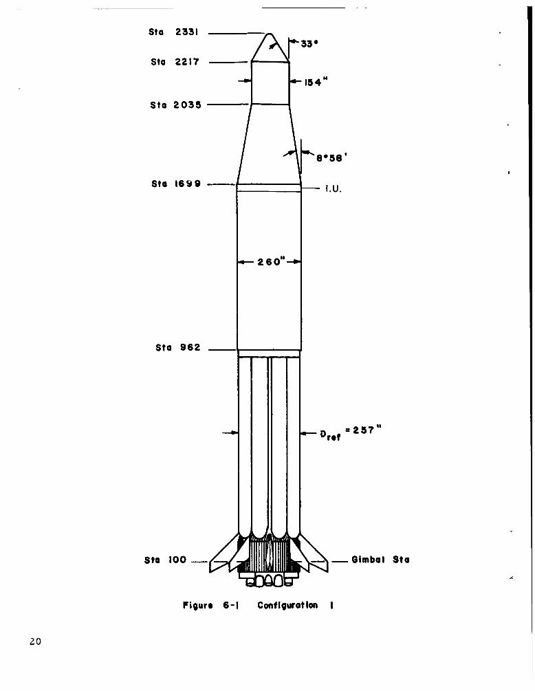
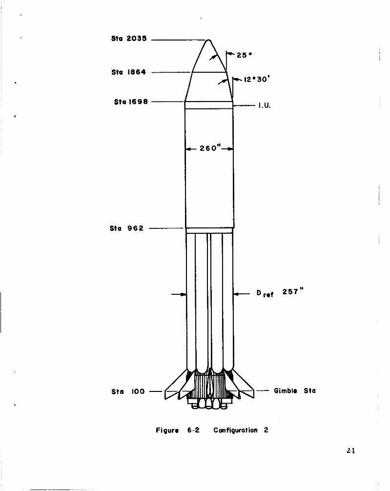
Two nose cone configurations were considered for use in the Liquid Hydrogen Orbital Experiment. consists of an Apollo payload shell. Configuration 2 (Figure 6-2) consists of a n aerodynamic nose cone envelope. If the Apollo configuration were used instead of the aerodynamic nose cone, the available hydrogen in orbit would be reduced by 1500 to 2000 pounds. This is due to approxi- mately a 2800-pound increase in S-IVB jettison weight in orbi t and different aerodynamic drag losses.
Configuration 1 (Figure 6 - 1)
Other studies have shown that control cannot be maintained using Configuration 1 when parameter variations are considered in conjunction with a 95 p e r cent wind speed profile. Reduction of the wind speed to the 90 p e r cent wind speed profile reduces the required gimbal angle sufficiently to maintain control. maintain control through the 95 per cent wind speed. to use Configuration 2 is a result of these studies.
Configuration 2 was able to The recommendation
B. DESIGN
The nose cone will be fabricated by MSFC. The cone will be a skin- and stringer-type construction and will have a coat of ablative material on the-exterior surface. Unit and will not be separated in orbit. 3500 pounds.
It will be bolted to the Instrument The weight will be approximately
C. INSTRUMENTATION :
The following measurements will be needed in the nose cone:
1 .
2.
3.
4.
5.
6 .
7 .
Pitch and yaw accelerations
Longitudinal acceleration (0 - 3 0 cps)
Internal acoustics (one pickup)
External acoustics (one pickup)
Eight static pressure measurements
Four unsteady pressure measurements
Twelve external temperature measurements (providing no additional telemetry is required)
19
15 4
Sta 2331
Sta 2217
Sta 2035
- -0 imbaI Sta
Sta 1698 -
Sta 962 -
4
G; Sta 100 -
= 257" - Drof
r' Figure 6-1 Configuration I
20

The above measurements must be transmitted by the Instrument Unit telemetry system and a r e second pr ior i ty to the television equipment in the Instrument Unit. The exact locations, accuracies, range, etc., of the measurements within the nose cone will be specified after the design is frozen.
22

SECTION VII. VEHICLE PERFORMANCE
A. PROPELLANT LOADING
The S-IVB propellant utilization system will be used to control propellant loading of the orbital cryogenic experiment stage thus main- taining continuity with the loading procedure used for other s-IVB stages at Kennedy Space Center. sensors , AP, etc. ) were not considered because of the required hard- ware modifications, percent for the hydrogen tank and approximately 65 percent (125,500 lbs) for the oxygen tank.
Other loading methods (point level
The approximate loading values will be 100
B. TRAJECTORY DESIGN
A design t ra jectory similar to that shown in Figure 7 - 1 must be constructed in order to satisfy the stated mission without objection- able vehicle compromise. jectories a r e characterized by excessive aerodynamic loads, t ra jectory shaping is believed to be necessary in order to insure the s t ructural integrity of the vehicle. to t ra jector ies marked by higher accelerations which in turn resul t from reduced configuration weight. differences, as compared to the operational Saturn IB mission, a r e a liquid oxygen off-load of approximately 60,000 pounds, deletion of the Launch Escape System, replacement of the Saturn IB Apollo payload with a 3, 500-pound aerodynamic nose fairing, and the addition of approximately 18,000 pounds of liquid hydrogen.
Since maximum payload capability tra-
Increases in aerodynamic loads a r e attributed
The principal system weight
C. DYNAMIC RESPONSE STUDY FOR STRENGTH ANALYSIS
In order to a s s e s s the structural integrity of Saturn IB vehicle SA-203, the dynamic response of the vehicle with respect to winds and gusts must be determined. defining maximum angle -of -attack histories that might be encountered.
This information will resul t in
D. VEHICLE STABILITY
c
It is necessary to insure that stability margins a r e maintained during powered flight. mission a r e vehicle moment of inertia, location of center-of -gravity and possibly center-of-pressure, and vehicle m a s s distribution. These
The basic parameters which a r e changed for this
23
Sto 1698
Sta 962
+
Sta 100 - - c;
c 260"-
Figure 6-2
- 1 2 O 30'
I.U. -
2 5 7 " C- D r e t
- Gimble Sto
Configuration 2
21

h
E 4: Y
II II II I1
0 @ v1
E E ' ? 34: Ea
0 0
0
0 0 m .. 4
0 0 '0 .. d
0 - 0
m
- 0
h
E 4:
M d rd CG
v
4
.
24

f
in turn result in new rigid body response and bending modes. Using these values, the vehicle stability must be examined at the appropriate burn t imes to determine the necessary changes in gains and shaping networks to insure maintaining the desired stability margins. addition, new propellant sloshing parameters will have to be determined to conform to the propellant loading and acceleration his tor ies peculiar to this mission.
In
E. LOX TANK SLOSH BAFFLE
Due to the low oxidizer fluid levels required for this mission (approximately 60,000 pounds less than the Saturn I33 operational mission) a new LOX tank anti-slosh baffle must be designed to insure three pe r cent damping effectiveness, At this t ime, no slosh testing is envisioned. Therefore, a conservative design will be used to guarantee the required damping without tes t verification. probably be either a horizontal ring o r a circular diaphragm with holes. The existing baffle will be left in place as it supports the propellant utilization ( P U ) probe.
The resulting baffle design will
F. PROPELLANT UTILIZATION SYSTEM
Stage flight will be accomplished with the propellant utilization system operating in the open loop mode. negligible P. U. system hardware changes. in the nominal position and will not be governed by tank propellant quantities. ratio unbalance caused by the hydrogen payload. is not possible with the existing P . U . system because of excessive hydrogen bias requirements. The entire payload m a s s would have to be biased out of the probe signal o r the P.U. system would see the payload as an apparent e r r o r and would attempt to eliminate it by operating the engine at a low engine mixture ratio (EMR).
This can be accomplished with The control valve will remain
This is necessary because of the excessive tank mixture Closed loop operation
.
The present maximum bias capability of the P . U . system is
This is well below the 17-18,000 pounds of liquid hydrogen conservatively sized at 5000 l b s of hydrogen based on Saturn V orbital boiloff. payload presently planned for the mission. bility to 18,000 pounds would require an increased voltage supply to the biased network and subsequent modification to the P .U . system.
Increasing the bias capa-
25

acceleration level ullage control for fif ty seconds after engine cutoff, during the shutdown transient, and t o assist settling for a portion of the simulated Saturn V/S -1VB orbital r e s t a r t sequencing.
Because of the relatively low orbiting weight of the experiment, only 28 lb total thrust will be necessary to simulate Saturn V/S-IVB orbital acceleration during burn of the 70-pound engines.
Basically the system will require two 3-inch l ines routed around the thrust cone to two nozzles located diametrically opposite each other in an axial direction from an S-IV o r S-IVB type f i l l and drain valve mounted on the side of an existing vent and relief valve tee. A control module must also be added t o actuate the added f i l l and drain valve.
A LOX residual will exist on the S-IVB stage due to tolerance in
The energy in the GOX-helium open loop flowrate predictions, flight performance reserves , and the possibility of a high performance engine. ullage thrusting system should not be affected by this residual, because the reduction in ullage volume caused by liquid residuals is negligible with respect to the total ullage volume.
Other possible a reas that could possibly be affected as a result of having liquid residuals a r e being analyzed to insure system integrity, although no problems a r e apparent at this time.
J. CONTINUOUS VENT THRUST LEVEL
The continuous vent thrust wi l l be sized to maintain a positive axial acceleration of approximately 2 X orbital coast , thus keeping the propellants bottomed. The exact thrust level will depend on the vehicle weight and the orbital drag. mum orbital drag was calculated for zero angle-of-attack and six-degree angle-of -attack. The six-degree angle-of-attack could occur as a resu l t of the tolerances in the guidance system horizontal reference plane.
g ' s on the stage during
The maxi-
K. AUXILIARY PROPULSION SYSTEM
The auxiliary propulsion system requirements a r e s imi la r to those of the Saturn IB mission with the possible elimination of all or at least a portion of the Saturn attitude control operations.
V type simulated maneuver exerc ises and There will be an increase in the hydrogen
27

G. REQUIREMENTS FOR A AV CUT-OFF-SYSTEM
It was originally planned to operate the J - 2 engine in the open- loop mode until LOX depletion occurs, thereby minimizing the amount of liquid oxygen onboard the stage during shutdown. Further investi- gation has determined that a significant amount of liquid oxygen could remain in the tank at orbital injection due to:
1. Tolerances on open loop flow rate predictions
2. Unused flight performance reserves
3 . Unused main-stage propellants which might not be ,consumed due to 3~ high engine performance.
Burning this residual LOX by operating to depletion woilld not signifi- cantly affect the experiment with respect to the total liquid hydrogen m a s s in orbit since the LOX will be consumed at an engine mixture ra t io of 5 / 1 . However, depletion of these residuals would impart a significant velocity increment to the stage and it would be impossible to hold the vehicle to the nominal Saturn V parking orbit and the vehicle would be injected into an elliptical orbit. the over-all validity of the experiment. Consequently, the stage will be shut down by guidance on the attainment of the nominal Saturn V parking orbi t with the attendant possibility of the higher liquid oxygen r e sidual s .
This would tend to decrease
H. S-IVB STAGE SEPARATION DYNAMICS
An analysis of the S-IB and S-IVB stage separation will be required in order to determine transient responses and the probability of collision. analyzed in order to demonstrate the range of separation conditions wherein control can be maintained.
The magnitude of these separation transients will be
I. ULLAGE THRUST SYSTEM
In order to simulate the thrust of the two Saturn V/S-IVB 70 pound thrust hypergolic engines, residual ullage gas from the LOX tank (oxygen-helium mixture) will be ducted overboard and directed axially through a pair of nozzles. The system will be used to maintain high
2 6

vent impulse which will resul t in additional APS propellant usage to counteract any vent induced disturbances. will a lso be required for (1) the cancellation of any ullage nozzle unbalance and ( 2 ) the production of a desired pitch o r yaw angular acceleration to determine its influence on continuous venting. of these two requirements is included in the present APS design.
Additional APS propellant
Neither
Based on preliminary analyses, the present Saturn IB APS design appears to be capable of satisfying the mission requirements although at the expense of at least a portion of the maneuver and attitude control exercises. However, the effect on the APS propellant require- ments of lower inertia values, changed CG location, and Isp variation as a function of pulse width will have to be evaluated in detail before the adequacy of the present APS propellant loading can be completely ascertained. Should the present loading prove inadequate, it is felt that a system parameter optimization (increased deadband, optimum minimum pulse bit, etc. ) and/or a small reduction in the allowable coast time for which attitude control is available could be used in lieu of a change in APS tankage.
.
L. HYDROGEN TANK REPRESSURIZATION SYSTEM
A hydrogen tank repressurization system consisting of a Saturn V ambient helium bottle with minimum liftoff and pad safety switches, actuation control module, approximately 2 0 fee t of 1 /4-inch tubing, and two normally closed shutoff valves will be required to complete the system simulation. The system will be used to deter- mine the pressure level that can be achieved by using a single ambient helium bottle and also to determine the orbital storage characterist ics of the bottle. integrity of the Saturn V repressurization system.
These parameters a r e needed to verify the design
2 8
SECTION VIII. S-IVB VENTING SYSTEM
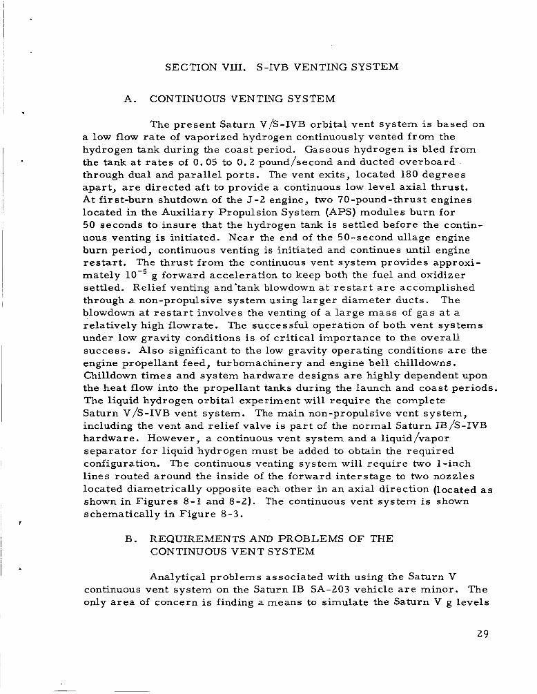
A. CONTINUOUS VENTING SYSTEM
The present Saturn V/S-IVB orbital vent system i s based on a low flow rate of vaporized hydrogen continuously vented f rom the hydrogen tank during the coast period. the tank a t ra tes of 0.05 to 0.2 pound/second and ducted overboard through dual and parallel ports. The vent exits, located 180 degrees apart, a r e directed a f t to provide a continuous low level axial thrust. At first-burn shutdown of the J - 2 engine, two 70-pound-thrust engines located in the Auxiliary Propulsion System (APS) modules burn for 50 seconds to insure that the hydrogen tank i s settled before the contin- uous venting is initiated. Near the end of the 50-second ullage engine burn period, continuous venting is initiated and continues until engine res ta r t . The thrust f rom the continuous vent system provides approxi- mately g forward acceleration to keep both the fuel and oxidizer settled. Relief venting and'tank blowdown a t r e s t a r t a r e accomplished through a non-propulsive system using larger diameter ducts. The blowdown a t r e s t a r t involves the venting of a large mass of gas a t a relatively high flowrate. under low gravity conditions i s of critical importance to the overall success. Also significant to the low gravity operating conditions a r e the engine propellant feed, turbomachinery and engine bell chilldowns. Chilldown times and system hardware designs a r e highly dependent upon the heat flow into the propellant tanks during the launch and coast periods The liquid hydrogen orbital experiment will require the complete Saturn V/S-IVB vent system. including the vent and relief valve is par t of the normal Saturn IB/S-IVB hardware. However, a continuous vent system and a liquid/vapor separator for liquid hydrogen must be added to obtain the required configuration. lines routed around the inside of the forward interstage to two nozzles located diametrically opposite each other in an axial direction (located as shown in Figures 8-1 and 8 - 2 ) . s chernatically in Figure 8 - 3 .
Gaseous hydrogen i s bled from
The successful operation of both vent systems
The main non-propulsive vent system,
The continuous venting system will require two 1 -inch
The continuous vent system is shown
B. REQUIREMENTS AND PROBLEMS OF THE CONTINUOUS VENT SYSTEM
Analytical problems associated with using the Saturn V continuous vent system on the Saturn IB S A - 2 0 3 vehicle a r e minor. The only a rea of concern i s finding a means to simulate the Saturn V g levels
2 9

3 I
I I
N H n
w *
4 I
oc)
w d 5 H
6(
3 0

I -
, .
2 w E
n
31

+ T
I I T I
N I J
Y 2 z
2 4
2 4 6 4
x u m rr) I
00
w d 5 * cr W
32

on SA-203. is considerably lighter than the Saturn V; thus, it i s necessary to reduce the thrust from the continuous vent system to achieve acceleration simulation. The apparent solution to this problem is to reduce the gaseous hydrogen flowrate from the ullage accordingly. in flowrate is so significant hydrogen tank pressure levels would differ drastically for the two vehicles. Therefore, this apparent solution is not acceptable. Two alternate solutions, which appear feasible, a r e shown below. Configu- ration A of Figure 8-4 shows a second se t of smaller nozzles opposite to the first pair. This would serve to cancel par t of the thrust produced by the larger nozzles, thus simulating the desired Saturn V g level. Configuration B of Figure 8-4 shows the two nozzles canted a t an angle such that the excessive thrust components in the axial direction a r e reduced to the desired level and the resulting horizontal components cancel each other.
This problem exists because the Saturn IB/SA-203 vehicle
The reduction (factor of 5), however, that the resulting
SMALL NOZZLE
NOTE: SMALL NOZZLE ACTS TO REDUCE AXIAL THRUST COMPONENT
CONFIGURATION A
HORIZONTAL COMPONENT CANCELS
CONFIGURATION B
FIGURE 8-4. CONTINUOUS VENT SYSTEM CONFIGURATIONS
3 3

1; Rate of motion of subject mat ter
2. Field of view of-subject matter
3. Minimum particle s ize to be distinguished
I ' An experimental tes t was made to determine the ability of
the TV system to meet the requirements stated above. white and color motion pictures were made inside a LHz tank during filling, pressurization and draining. surface motion, turbulence, o r bubbling was clearly visible. It was decided to employ a high rate (30 f rames per second) system to observe the turbulance during injection into orbit and during high speed venting.
Both black and
The pictures showed that any
A low rate TV system will be used as a back-up to the high rate system and also to provide visual observations whenever the experiment i s within range of receiving stations having only te lemetry capability. would be economically impractical, since it would necessitate the in- stallation of additional high-rate receiving stations. can use the existing on-board single-side-band t ransmit ter and existing telemetry ground stations to receive and record the information. system will make pictures every two seconds, which will permit a good analysis of the equilibrium condition in the tank. strength and signal to noise ratio of the received picture was made. a r e tabulated on Table 9- 1. possible alternates and a r e shown here for comparison. minimum detected S /N While all four frequ&%)cies were acceptable f rom the 26 db point; overal l system complexity and problems involved with 870 mc and 1700 mc systems eliminated them f rom consideration. In the process of arriving at the results given in Table 9-1, the t ime the vehicle would be over each of three high rate stations on each orbit was checked to ensure that the desired functions in the vehicle could be viewed. One of the high rate (30 f rames per second) stations will be located at Guaymas, Mexico o r Hawii dependent on chosen vehicle and station operational dates. The other two stations will be located at Kennedy Space Center, Florida, and Bermuda. Conservation of battery power plus three high-rate stations limitations predicated that the high-rate camera be turned on as the vehicle in orbit approached the most westerly station, and be turned off as it left the most easter ly station of the three-station group. been recommended that ground commands be used to activate the high-rate
The use of a high-rate system for the entire orbi ta l coverage
The low-rate system
This
An analysis of signal These
Two other frequencies were checked as
was taken as 26 db for this experiment. An acceptable
rms
It has
35

0 m m id Ei c,
9 4 VI Q) 4
0 9 e
k .. %
nl
tF I'
I
u % E : % %
rn Q)
.rl
0 0 0 0
3 d 4 c ; I I + I
o d * o o t F d o m m
In + m * + Y
3 0 nl
nl
tF I'
I
E
c rn .. 5 M E: Q) k
Y
i! z" \
rn
k E:
5 tn
;x 0 m c,
cd N k
.I+
6 36
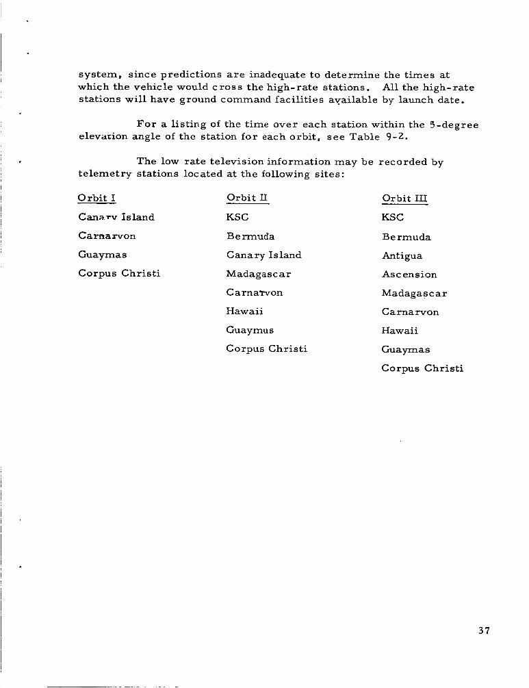
system, since predictions a r e inadequate to determine the t imes at which the vehicle would c r o s s the high-rate stations. stations will have ground command facilities available by launch date.
All the high-rate
F o r a listing of the time over each station within the 5-degree elevation angle of the station for each orbit , s ee Table 9-2.
The low rate television information may be recorded by telemetry stations located at the following sites:
Orbit I
Canarv Island
Orbit II
KSC
Orbit III
KSC
Carnarvon Be rmuda Bermuda
Guaymas Canary Island Antigua
Corpus Christi Madagascar Ascension
Carnarvon
Hawaii
Madagascar
C a rna rvon
Guaymu s Hawaii
Corpus Christi Guaymas
Corpus Chris t i
37

N
4
VI d
0
VI
d VI
m 4
F
4
F 9 d N
VI
4 9
4
(I)
G 0
n d 0
Id .rl c,
rl w 0 VI
N N
4 N
.rl c, d ;5 Q) c,
2 9 0
VI
0
VI P 4 e, M Id k Q) > 0 u 4
c,
k
d
2 0 Y
+ 0
Q)
E .rl
E-l N N
N ul
VI
4
N co
H
2 3 4 x
F: 0 w
PI 4 u
.rl c,
38

c. IMPLEMENTATION OF TELEVISION SYSTEM
The development of the television system wil l be the responsi- bility of the Astrionics Laboratory, supporting electronics will be performed by contractors and IBM will integrate the systems into the IU.
Testing and minor changes of the
A hydrogen tank manhole cover containing one low-rate camera. one high-rate camera and two 28-volt lights in separate housings will by provided by MSFC for installation in the S-IVB stage at Sacramento. The necessary equipment for ground checkout of the TV system will be sent along with an MSFC tes t engineer to the tes t site. firing DAC will provide a purge for the cameras and lights. flight vehicle there will be only a ground purge supplied by MSFC.
During static On the
The airborne stages of the television system a r e block diagram form in Figure 9-1 and the viewing angles are shown in Figure 9-2.
shown in
The system wil l use the following equipment:
1. 2200-mc t ransmit ter including dr iver and power amplifier (high-rate) -- 10-mc bandwidth, 20 watts output power
2. Minature TV camera with camera control unit - 30 f rames pe r second interlaced 2: l
3. Antenna - 2200 mc
4. Light (two required to serve both cameras)
5. TV camera with camera control unit (Ranger VI1 type) - 1 /2 f rame per second
6 . 250-mc telemetry t ransmit ter (SSB) - already included in vehicle
7. Antenna - 250 mc already included in vehicle
F o r the purposes of this experiment, the power amplifier portion of the 2200-mc t ransmit ter will require the installation of a 2 8 - d ~ power supply to replace the existing 115-volt, 40Gcycle %phase supply. dr iver portion of this transmitter is built but will require qualification to MSFC environmental specifications. I
The
39

- t3
$- W E
4-
J W
>
e W t- t- s z U E t-
v)
P =E 0 0 N N
I
K w W Z W 3 U W v)
40

\
\ I /
- MOOIFIED -MANHOLE .'/ I \ CC~VFR -WITH TV --- -.. ... . . . \ CAMERAS 8 LiGHTS
/ \\ I //
'4 \
H RATE CAMERA
I
INSTR.
/- "*IT
FIGURE 9-2. TV CAMERA AND LIGHT INSTALLATION

The ground television stations are shown in block diagram form in Figure 9-3.
The 250-mc stations required to receive the low-rate TV pictures a r e in existence. ra te TV system a r e planned and the 100% operational dates a r e given below:
The 2200-mc stations required by the high
Bermuda November 1966 Hawaii January 1967 KSC February 1967 Guaymas March 1967
For3he’purpose of this experiment, the entire station does not have to be operational. However, the 30-foot dish antenna and the receiver must be operational, and it may be necessary to speed-up the installation of these two items at each of the required tracking stations.
MSFC will supply a standard video tape recorder to record A real-time presentation of the the receiver output of these stations.
2200-mc receiver information will be available. will use existing tracking stations used for receiving standard wideband telemetry. The receiver output will be recorded on standard wide-band telemetry recorders. the 250-mc channels.
The 250-mc system
No real-time presentation will be available for
A tape-to-file converter will be used for data reduction. It will be located at MSFC. station will be played into it. will be done by the converter. unprocessed 35 mm film roll. rate display, but a Polaroid camera will be available to provide immediate hard copy when required. 16mm, 30 frames-per-second movie films at MSFC for evaluation.
The low-rate video telemetry tapes from each All synchronizing and photographic operations
The output f rom the converter will be There will be no visual real-time low -
The high-rate video tapes will be made into
D. EXPERIMENT INSTRUMENT ATION
Most of the present Saturn IB/S-IVB p res su re and temperature instrumentation will be used to obtain data for the experiments; however supplemental liquid-vapor interface and temperature sensors in addition to the television systems will be required. required instrumentation and their priority.
Table 9-3 is a list of the Locations of this
42

4 Z Z W I- Z 4
I
1
Z 0
U i= 5 > k w t- L1? a
Y W
Z 2 IC! > w -I W k
43

44
Liquid vapor separator RPM 1 I
Table 9 -3. Pr ior i ty of Additional Installed Instrumentation
r ior i ty Objective Instrumentation Total
l 1 Verification of continuous Valve talkback vent sys tem capability 3
Anti-vortex screen vapor removal Liquid vapor sensor 1 Temper a tur e 1
Main vent P r e s sur e Temperature
2 1
Count of vent opening and closing 1 I Continuous vent
P r e s s u r e Temperature
GOX ullage system P r e s sur e Temperature
2 1
2 2
LHZ ullage p r e s s u r e 1
Longitudinal 10-5 g ' s 1 Accelerometers (during orbital coast phase)
Pitch
Roll Yaw I 10-2 gls 3
Liquid vapor sensors (mounted on probe B) 4
Helium repressurizat ion bottle (ambient) performance
P r e s s u r e 1 Temperature 1
Total First Pr ior i ty 28

' T
I .
I.
W
CI rn Q) k (d
2 .r(
M E Q)
E
a Q)
rd V 0
Q)
.rl
U
.-I Y
2
i? (d k 0)
Q) E
E
2 44 c, m
N
N
E 0 Q)
E a E id rn
N N
m i
-
Q\ 9
* x k 0
U .rl
.rl
t z c M
k c E 4
c, rd 0 E
45

SECTION IX. EXPERIMENT INSTRUMENTATION
A. PURPOSE
The purpose of this experiment is to confirm the low gravity S-PVB stage venting system on the Saturn V/S-IVB, and to confirm chill- down of the J-2 engine. during:
This entails observing the reaction of LH2
1. Engine shutdown at insertion , 2. S-IVB stage ullage engine firing
3. S-IVB stage continuous venting
4.
5.
S-IVB stage high speed venting
J - 2 engine c hilldown
6 . Second firing of S-IVB ullage engines for fuel settling
7. Second high rate S-IVB venting
8. Propellant sloshing due to attitude control motors
These observations should show action of liquidhapor separator, I wall creep of LH2 and turbulance of LH2 when vents a r e operated.
B. TELEVISION REQUIREMENTS
The television camera will observe the liquid vapor interface during the experiment. Specific operations to be observed a r e engine shutdown at orbital injection, ullage engine firing, continuous venting, high speed venting, and liquid sloshing induced by attitude control motors. A tes t was conducted to determine the minimum satisfactory image resolution. hundred horizontal lines and two hundred horizontal lines were shown. A minimum resolution of two hundred lines was chosen for the television system outputs. yielded three major points for consideration:
Television pictures, with resolutions of both five
The requirements of the TV portion of the experiment
34

h a a, a 5 V d 0 u
"
Y
W t o\
a,
? E+
9 1 cu
(d
(d a c,
5 a,
ld a, s k a,
4
c,
46

I '
instrumentation a r e shown in Figures 9-4 through 9-8. to be meaningful all of the instrumentation listed through priority four should be installed. but not mandatory. sensor , etc. is not specified but wil l be determined la ter by mutual agreement between MSFC and DAC. each transducer (even the temps.) to determine their usefulness in a low gravity environment. trapment of liquid in smal l crevices in the instrument thus giving false indications of liquid level.
F o r the experiment
The other measurements a r e highly desirable The exact type of accelerometer, liquid-vapor
It will be necessary to evaluate
The main problem anticipated is the en-
A quality me te r is under development by MSFC but the data needed for its consideration for inclusion in the experiment is not presently available. However, the quality meter has ' # l priority and it will be installed la te r even i f other, lower priority measurements must be deleted. is entrapped in the anti-vortex screen i s under consideration. stated about the quality meter applies to this device.
Also, a device to determine whether o r not vapor Everything
Since no particular functions involving the LOX tank a r e planned,. LOX tank instrumentation will consist only of the existing measurement program.
The additional measurements, with the exception of the TV system, will be handled in the same manner as existing measurements, regarding implementation and automatic checkout,
The electr ical leads f o r measurements inside the liquid hydrogen tank will be brought out through an existing instrumentation feedthrough. but will not have to perform any s t ructural modifications.
DAC will have to change the pin connector configuration
47

c
48

LEGEND
A Liquid Vapor Sensor X Temperature 0 Pressure
Miscellaneous
0 AP
Counting Device
( Number of times main vent opens and c l o s e s )
Valve talkback
Separator
Anti- vor t ex screen
Main Vent I
Continuous Vent
4 A t least two u l lage pressures (redundancy desired)
0 4 Accelerometers I I O Longitudinal- 10- a/go - 0 Pitch
10-2 a/go Roll
Valve talkback
Ambient helium sphere
FIGURE 9-5. ADDITIONAL INSTRUMENTATION REQUIRED FOR SATURN IB ORBITAL HYDROGEN EXPERIMENT
49

3 emperatures for recirculation system
1 8 temperatures measure liquid boundary layer
stratification
to
FIGURE 9-6. ADDITIONAL INSTRUMENTATION REQUIRED FOR SATURN IB ORBITAL HYDROGEN EXPERIMENT
50

Typical Cross
Internal
Section A-A
insulation
Cross section B-B typical for domes. Cross section A-A
II Liquid Level
A A
typical for sidewal # Cross section B-B typical for domes. Cross section A-A typical for sidewal
Gox ullage system
FIGURE 9-7. ADDITIONAL INSTRUMENTATION REQUIRED FOR SATURN IB ORBITAL HYDROGEN EXPERIMENT
.l.
51

insulation
Typical Cross Section B-B (See Figure 9 -7 )
A l l f i v e of these measure- ments must be accommodated by the I.U. s p e c i f i c a l l y requested by the Structures Branch but are second priority t o TV equipment i n the I . U .
They have been Pi tch Yaw Longitudinal
Acc e 1 erome t er s 1
nternal and external acoustic pickup
Nose Cone
FIGURE 9-8. ADDITIONAL INSTRUMENTATION REQUIRED FOR SATURN IB ClRBITAL HYDROGEN EXPERIMENT
52

E. TELEMETRY SYSTEM
I '
l -
Figures 9-9 through 9-12 contain the present channel loading information fo r S-IVB stage . on link No. 1, a s programmed, may accept fifty additional 12 samples- per-second measurements and five measurements sampled at 120 samples - per-second. at 12 samples-per-second. by Figure 9-9 at 4 samples-per-second (not presently turned on during flight). 9- 1 1 and 9-12 show the aft mounted multiplexer loading. The unit on PAM link No. 2 has 4 open 12 samples-per-second channels. The unit on PAM link No. 3 has one prime 120 samples-per-second channel open, but may be reprogrammed and the channel assignment changed to pro- vide 10 additional 12 samples -per-second channels. There is, therefore, more than adequate channel capacity forward and a total of 14 possible openings aft.
They indicate that the forward multiplexer
I t may be reprogrammed for 100 additional measurements
is relatively empty and could accomodate many channels Figure
The "Checkout Only" multiplixer as indicated
Figure 9-13 details the module space and decoder lines remaining on the various racks in allSaturn IB stages. Capacity at this point is limited by either space o r line availability for automatic checkout. If we assume two spaces f o r temperature measurement (bridge module and amplifier) and a requirement for two decoder lines per measurement (20 and 80 per cent calibration), an approximate capacity figure per rack may be determined by using the smaller r e - sulting figure. 61 modules forward and 41 aft.
Following this procedure, it appears possible to mount
The composite capacity of the present telemetry system, considering both channel and space availability, is 75 measurements. This allows 61 measurements forward and 14 measurements aft. Measurements in addition to the 7 5 will require additional cold plates for the mounting of signal conditioning, amplifiers, etc .' Additional measurements may be handled forward, without additional cold plates, i f they a r e of a type not requiring signal oonditioning o r decoder lines for checkout i. e. , potentiometer type transducers.
Telemetry system modifications a r e relatively few in number, primarily consisting of multiplexer programming to handle the eighty- eight new measurements and the possible activation of the "Check Out" o r A 3 multiplexer at liftoff.
5 3

rl T
N c
N
-&--
w d
54

.
i .
r r
tii T
i N
h h h h h n d 4 3 pc: 0 B
4 c) 0 4
0 z
55

* h
m
-&
4 h
-@-
I I I I I I I I I l l
N
&
N --& 'LI 0
t, m
B
56

N
6- d
h
-@-
I;;;; * d d d d h h h h h J
d -&-
m h
N
-&
d -&
N -6-
-6- N
H cr 4
I
m
d z
5: 2 N 4
I rn w d s n
cr
5 7

k a J m aaJ
2 z 4
-+ 4 4
\
- 0 hl
12003 1
21 2004 I 12003
21 2002 I
58

I?. HYDROGEN EXPERIMENT - GENERAL COMMENTS
1. Space is available in the Instrument Unit to mount related electronic equipment for the T V System.
2. Ground commands w i l l be required to per form the ex- periment. planned have the capacity to meet this requirement. ground stations have the command capability.
The Command System and the switch selector presently All recommended
3. The Instrument Unit Telemetry System can meet the requirement to telemeter five measurements f rom the nose fairing. No impact on schedule, manpower, o r cost is anticipated for work other than TV.
4. is required on the number of vents that occur. using a counting device.
Tape recording in orbit is not a requirements but data This can be accomplished
5. The DAG feed-thru must be redesigned to accomodate the additional measurement requirements in the LHz tank. This will eliminate a requirement for a feed-thru in the manhole cover.
59

SECTION X. S-IVB STAGE MODIFICATIONS
A. PROGRAM PLAN
Douglas Aircraft Company will design, fabricate and supply
Figure 10 - 1 shows a schematic’ of the modified MSFC a S-IVB stage modified to incorporate a Liquid Hydrogen Orbital Experiment. stage. The modifications and/or additions will consist of:
1. Continuous Vent System
2. Gaseous Oxygen/Helium Thrusting System
3. Liquid/Vapor Separator
4. Helium Sphere and Associated Plumbing
5. Liquid Hydrogen Tank Instrumentation Support Structure
6. Instrumentation ( LH, Tank)
7. Battery
8. LOX Tank Baffle Modifications
9. Telemetry Modifications
10.
11. Sequencer Modifications 2
Insulation on Forward Dome (LH, Tank)
These modifications and/or additions will require the following engineering effort:
1. P repa re specifications for the following:
a. Liquid/vapor detectors
b. Accelerometer to measure g
c . Instrumentation feed-thru (new configuration)

Continuous Vent Sys tem
Telemetry Modifications
Saturn V Insulation on Forward Dome LH2 Tank
Instrumentation Tank Support Structure
1- Ullage Thrust System (GOX Blowdown)
Sequencer Modifications
FIGURE 10-1. M~DIFICATIONS TO S-IVB FOR LIQUID HYDROGEN ORB1 TAL EXPERIMENT
61

2. P repa re layout, installation and detail drawings for:
a. Propellant Tank Repressurization System
b. Hydrogen Tank Instrumentation Support Structure
LOX Tank Ullage thrusting system
LH , continuous vent system
LH, Tank Instrumentation Routing and Feed-thru
c.
d.
e.
f . Ullage Thrust Nozzle Support
3 . Prepa re layout, installation and rework drawing for:
Forward Dome Ring (Support Clip Attach) a.
b, Battery Installation
c. LOX Tank Baffle
d. Continuous Vent Support Structure
4. Prepa re rework drawing for insulation on forward dome and aft dome
5. P repa re installation drawing for insulation on forward dome - LH, tank
6. Modify drawing 1A39322 {Tank Components Installation, Main Fuel (Saturn V) - Installation Drawings and Detail Drawings) to add liquid/vapor separator, continuous vent lines, thrust nozzle (resized) and support shut-off valve (pneumatic), actuation control module, pneumatic control plumbing and support
7- Prepa re Network Control Drawing (top schematic book, cable network diagram, advance functional schematics) for:
a. Continuous vent system
b. LOX tank ullage system
62

c. LH, tank repressurization system
d. Camerall ight purge I -
! . 8 , Prepa re instrumentation drawings for the connection of
t ransducers within an external to the LH2 tank, suction line inlet, vent system, recirculation system to their signal conditioning and/or telemetry system. This will consist of:
a. Electr ical Schematics - Control System
b. Cable Networks
c. Sequence Diagram
d. Advanced Functional Schematics
e. Tes t Requirements Drawings
f. Power Distribution Design Requirements Drawings
9 . Prepa re Mechanical Installation Drawings for:
a, Temperature and p res su re transducer installation on helium sphere and for repressurization system
b. Transducer installation - contirmous vent system
c. Transducer installation - main vent
d. Accelerometer installation - LH experiment
e. Harness installation - signal conditioning racks, forward
f, Harness installation - signal conditioning racks, aft I .
10. Modify existing electrical and mechanical installation drawings
I - a. Wiring installation - patch external
b. Wiring installation - probe internal (LH, tank)
6 3

c. Battery installation - forward
d. Hole installation - forward skir t
Instrumentation installation - panel mounted forward
Instrumentation installation - panel mounted aft
Ground plane installation - forward
Ground plane installation - aft
Electr ical equipment installation - panel mounted forward
Electr ical equipment installation - panel mounted aft
Rack assembly forward signal conditioning
e.
f .
g.
h.
i.
j ,
k.
1.
m. Sequencer assembly
n. Control distribution, forward
0. Control distribution, aft
p. Power distribution, 2 8 volts, aft
q. Power distribution, 2 8 volts, forward
r , Harness installation - forward skir t
s. Harness installation - aft skir t
t. Harness installation - tanks
Rack assembly aft signal conditioning
.
u. Harness installation - sequencer
v. Harness installation - forward control distribution
w. Harness installation - aft control distribution
64

x. Harness installation - 28-volt aft power distribution
y. Harness installation - forward power distribution
11. Design and construct one piece of additional e lectr ical ground support equipment (LH2 tank T V monitor) to utilize DAC and GFE items. This will require the following engineering effort:
a. P repa re design requirements drawing
b. P repa re cable drawing
c. P repa re top assembly drawing, schematics, and wire diagrams
d. P repa re detail drawings of DAC items
e. Generate functional and EMC test documents
f. P repa re new GSE drawings required to install GFE i tems
12. Perform programming and patching changes to the automatic checkout equipment to provide:
a. Command and monitor response of gaseous oxygen ullage thrusting system valve
b. Command and monitor response of continuous vents
c. Ground power and monitoring for camera heater and lamps
d. Battery load tes ts
e. Command for forward buss 3 internal-external switch
f. Monitoring for forward buss 3 (DDAS o r hardwire)
g. Strip out and programming of additional instrumentation
'h;\ Camera control power during checkout and static firing
i. Checkout procedure for additional harness and equipment installed at Huntington Beach
65

13. Provide checkout procedure to checkout experiment-peculiar hardwar e
14. Generate drawing re lease schedules, task plans and job drawing list
15. P repa re and issue procurement instructions for slow delivery i tems including:
a. Liquid/vapor detectors
b. P r e s s u r e t ransducers
c. Accelerometers
d. Instrumentation feed -thru
e. Battery
f. Liquid/vapor separator
g. Ambient helium sphere
16. P repa re and issue memo re leases for:
a. Saturn V insulation for LH2 dome
b. Feed-thru port (instrumentation)
17. P repa re measurement request drawings for additional ins t rum entation
18. Pe r fo rm required tes t planning and requirement evaluation of expe r imentpecul ia r hardwar e
19. Per form de sign evaluation testing on experiment peculiar hardwar e
20. Per fo rm electr ical load analysis for battery sizing
21. Analyze the effect of higher "g" loading on cylinder walls, common bulkhead, aft dome, and thrust structure
66

22. Perform design analysis on ullage thrust simulation system
a. Simulate 70-pound Gemini ullage engine "g" levels at orbiting weight of Saturn IB using LOX tank ullage gas as an energy source
b. Determine optimum system control and thrust histories
c. Determine m a s s flow ra tes and LOX tank ullage p res su re his tor ies that a r e consistent with required simulation of Saturn V duration, yet do not deplete LOX tank ullage pressure so as to endanger the common bulkhead
d. Per fo rm design analysis to size necessary system hardware
e. Determine probable vent thrust unbalance
23. Per fo rm design analysis on hydrogen tank blowdown system
a, Check line and orifice s izes to insure that Saturn V p r e s - sure his tor ies a r e accurately represented
I .
b. Determine need for aft facing exit nozzles to replace thrust lost from continuous venting system as a resul t of being partially starved out during blowdown process
c. Determine probable vent thrust unbalance
24. Per fo rm design analysis on hydrogen tank continuous venting system:
a. Check line and orifice s izes to insure that Saturn V p res su re histories a r e accurately represented
b. Check item 23. a. above with respect to simulation of Saturn V orbital acceleration levels during continuous venting. Determine need for nekessary system modification to satisfy both requirements, i. e . , cor rec t p re s su re levels and acceleration levels
c. Determine probable vent thrust unbalance
67
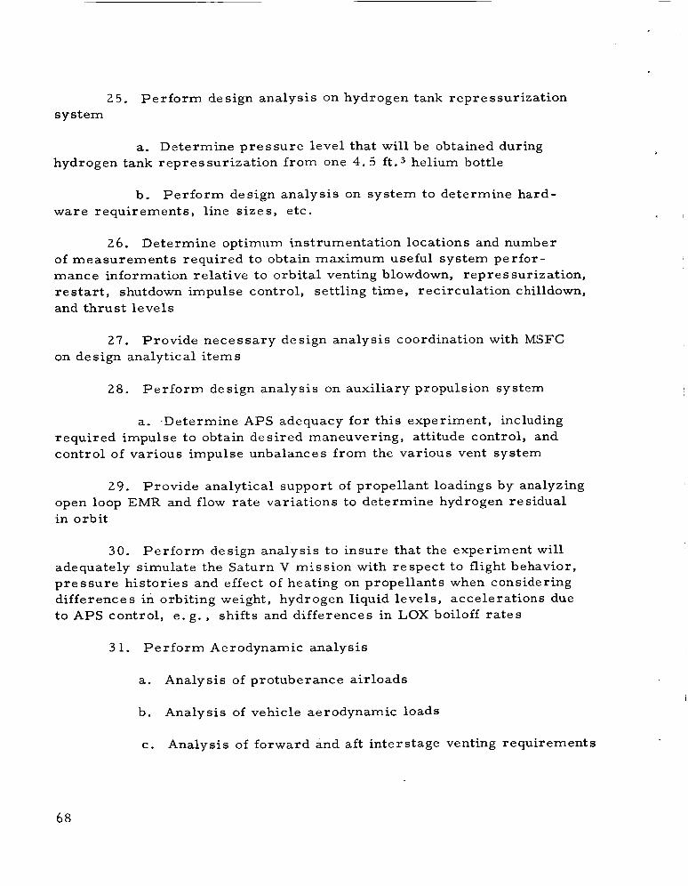
2 5 . Perform design analysis on hydrogen tank repressurization system
a. Determine pressure level that will be obtained during hydrogen tank repressurization from one 4. 5 f t . 3 helium bottle
b. Per form design analysis on system to determine hard- ware requirements, line s izes , etc.
26. Determine optimum instrumentation locations and number of measurements required to obtain maximum useful system perfor- mance information relative to orbital venting blowdown, repres surization, r e start, shutdown impulse control, settling t ime, recirculation c hilldown, and thrust levels
2 7 . Provide necessary design analysis coordination with MSFC on design analytical i tems
28. Perform design analysis on auxiliary propulsion system
a, .Determine APS adequacy for this experiment, including required impulse to obtain desired maneuvering, attitude control, and control of various impulse unbalances from the various vent system
29. Provide analytical support of propellant loadings by analyzing open loop EMR and flow rate variations to determine hydrogen residual in orbit
3 0 . Perform design analysis to insure that the experiment will adequately simulate the Saturn V mission with respect to flight behavior, p ressure histories and effect of heating on propellants when considering differences in orbiting weight, hydrogen liquid levels, accelerations due to APS control, e. g . , shifts and differences in LOX boiloff r a t e s
3 1, Per form Aerodynamic analysis
a. Analysis of protuberance airloads
b. Analysis of vehicle aerodynamic loads
c. Analysis of forward and aft interstage venting requirements
68

32. Perform structural heating analysis
a. Analysis of aerodynamic heating effects on basic structure
b. Analysis of protuberance heating effects on fairings and in the surrounding regions
c. Analysis of plume heating effects based on hotter s t ructural temperatures established in 3 . a. and 3 . b.
d, Determination of insulation requirements based on 3. a. , 3. b., and 3. c.
33. Perform propellant heating analysis
a. Determination of the boost phase heat input into pro- pellant tank through tank walls, forward and aft bulkhead and heat shorts
b. APS propellant temperature analysis
c. Analysis of ullage rocket propellant grain temperatures and temperature gradients during ground hold and boost
d, Determination of propellant conditioning requirements (active ground conditioning, fairing external surface coatings, insulation, e tc . ) based on 32. c.
34. Perform component heating analysis
a. Analysis of selected components such a s the antennas during boost and orbit
35. Perform LOX sloshing analysis in order to insure 3 per cent damping effectiveness through LOX tank baffle modification
36, Construct o r simulate the trajectory required to achieve the mission conditions
37. Provide assessment of the vehicle dynamic response charac te r - is t ics in order to insure adequate control, to obtain angle -of -attack histories for inputs to airload calculation, analyze zero - g to insure satisfactory performance of the APS system for this mission
sloshing and
69

38. Per fo rm an evaluation of the S-IVB performance character- ist ics as affected by the employment of employing an open loop P . U . system
3 9 . Perform S -1VB stage separation dynamics
40. Per form stage bending and sloshing analysis
41, Per form a s t r e s s analysis on the main propellant tank, ambient helium bottle installation, rework for additional battery in forward skir t , LOX tank baffle rework, forward skir t rework for continuous vent
42. Pe r fo rm weight es t imates for evaluation of weight effects on performance and cost
43, Maintain detailed weight records on experiment peculiar hardware
44. Conduct a Quality Control effort in accordance with the applicable portions of SM-41891, as defined in Section XIV
45. Conduct a Reliability effort in accordance with the applicable I
portions of SM-46644, Formal Reliability Program Plan, a s defined in Section XIV
46. Provide the technical documentation specified in Section X I
47. Pe r fo rm postflight data evaluation and correlation
The modification to the S-IVB stage and the electrical ground support equipment will require the following manufacturing effort:
1. Planning
a. P repa re and issue Planning paper for detail par t s , sub- assemblies, assemblies, installations, production acceptance testing and checkout procedures
b. Issue the o rde r s per detail and installation tools, produc- tion data sheets and production tes t equipment
c . Maintain support effort
70

2. Manufacturing Engineering and Design
a, Provide support for Planning, MR&PM, Plant Engineer- ing for tooling and facility requirements
b. Prepare sketches, flow charts
c. Provide expeditious handling of tools and equipment
d. P repa re tool design, tool data sheets and production data sheets
3 . Production Test Engineering
a. Provide Support Planning, MR&PM, Plant Engineering for tooling and facility requirements
b. Provide production data sheets and pr,oduction tes t equip- ment design for checkout of wiring, components and systems electrical/ ele ctr onic components requiring receiving functional testing include s wire harnesses modules, pressure transducers and wire feed thru fitting, Structure details which require testing or calibration include nozzles, tubing, helium sphere and valves
4. Tool Fabrication
Fabricate, assemble, and inspect tooling and production tes t equipment. brackets will require use of single installation tools
Installation tools for battery brackets and probe support
5. Manufacturing
a. Fabricate, assemble and inspect metal components. These items include probe structures, vent and ducts, and miscellaneous sheet metal par t s
b. Fabricate, assemble and/or modify and check out electrical and electronic assemblies, such a s signal conditioning module s with welded modules and printed circuit boards
c, Install metal details and assemblies, and electronic and electrical assemblies
71

I d. Fabricate details, assemble and/or modify and check out GSE required
e. Modify existing s t ructure and electr ical and electronic components of vehicle to conform to new configuration
f. Check out modified vehicle
B. MODIFICATION INSTALLATIONS
The installation of details and assemblies for the modification will take place, schedule permitting, at the Santa Monica and Huntingtor. Beach facilities. provided in time for installation on the line o r a t Huntington Beach w i l l be installed at Sacramento Tes t Area. for this modification program a r e discussed below:
Those components which cannot be manufactured o r
Major installations to be made
The Probe installation, for instrumentation, consists of one
The side fittings a re attached to the tank main tube, b races to support, and fittings for attachment to tank walls, and manhole cover flange. walls with welded studs, on the helium bottle support pads. The stud locations are determined by use of an installation fixture. The upper fitting on the manhole flange is located dimensionally. The clips and fittings for the probe installation a r e installed pr ior to cleaning of tank. The internal insulation will require modification to provide clearance for these installations, After installation of insulation, the probe and its braces a r e installed, in the LH, tank, concurrently with the propel- lant utilization and instrumentation probes a t the Huntington Beach facility.
The helium bottle support is installed on the thrust structure This work is accomplished at assembly using an installation fixture.
on the tank. I the Huntington Beach facility pr ior to the thrust s t ructures installation
The manhole cover assembly is the responsibility of Mar shall
The Missile and Space System Space Flight Center for fabrication, assembly, testing, and shipment to Sacramento Tes t Operations (SACTO). Division a t Huntington Beach will use an existing tool as a dummy cover for hydrostatic testing of tank and an interim cover will have to be pro- vided until the MSFC supplied cover is installed at SACTO.
72

.
The new battery brackets will be installed by use of a simple installation fixture and is accomplished at Huntington Beach after completion of forward skir t structure assembly and p r io r to s t ructure installation on tank.
The anti-slosh baffle installation consists of miscellaneous clips and formed sheet metal baffles and i s installed in the LOX tank at Huntington Beach. accomplished pr ior to LOX tank being joined to cylindrical and forward dome sections.
This structure can be located dimensionally and is
The aluminized mylar insulation is installed on the forward dome
Special at Huntington Beach and requires only layout templates. is bonded to the forward dome and is cured at room temperature. tools o r facilities a r e not required. tanks a r e in tower pr ior to forward skirt installation.
This insulation
This insulation is installed while
The modification of the forward skir t for installation of vent system is accomplished at the Sacramento facility. in the skir t structure a r e utilized and new nozzles and fairings a r e installed. installed at Huntington Beach a s final assembly modification type work. These systems will be given final tes t s and checkout pr ior to shipment of vehicle to the Sacramento facility.
Existing vent holes
The propulsion sub system details and components will be
C. STRUCTURAL MODIFICATIONS
The s t ructural modifications for the LH, experiment consist of a probe assembly, additional baffle ring and miscellaneous clips and bracket iy for mounting the added battery and helium bottle. components a r e manufactured using a "no tool" philosophy due to the quantity of ar t ic les being produced.
These
The probe assembly consists of approximately one 40-foot length of standard 3-inch aluminum tubing. to which a r e attached brackets which locate and hold the sensing units. Also, attached to the tube a r e four a r m s that provide a lower end support. These four a r m s a r e fastened to a bracket which is located on the tube and to the tank by bolting in the a rea of the helium bottle pads. The upper end of the support is secured to the manhole attach flange by pinning through the bracket and tube. The above i tems will be manufactured using
This provides the main support
73

standard shop equipment a s table saw, power brake, standard punch p r e s s dies, a lathe and a mil l in conjunction with comimon shop techniques. Subsequently, a continuity check, visual inspection, and LOX cleaning a r e performed pr ior to installation.
The added baffle assembly is manufactured s imilar to the existing baffle, It is made of sheet metal using shears , rolls, and standard punch p r e s s tooling. required. After a visual inspection, the baffle is shipped to the LOX Tank Assembly a r e a for installation.
In addition a contour template will be
The battery brackets and helium bottle brackets will be made from standard extruded stock o r formed sheet metal, Standard sheet metal shop equipment as a shears and saw, power brake, and a dr i l l p r e s s will be used to manufacture these components, After inspection, p r imer and paint, the brackets a r e shipped to final assembly area. A layout template for each set of brackets will be required.
The mylar insulation is hand cut and fitted to the forward end of the LH2 tank, After the prefitting operation, a room temperature curing adhesive is applied to the mylar and it is located on the tank. layout template is used for cutting the mylar section.
A
D. LOX BAFFLE MODIFICATION
The LOX tank will be off-loaded to meet the mission require- ments, the present baffle rings will be ineffective. An additional anti- slosh ring will be installed at DAC station 254. 000 and will be approxi- mately 2 4 inches in width ( see Figure 10-2): with gussets as required to support the expected 0.3 ps i slosh loading. To maintain present installation schedules, the additional baffle ring must be added by reworking the present baffle after installation in the LOX tank, The ring must necessarily consist of many small segments spliced together inside the tank in order to allow passage of the pieces through the thrust structure access door and the LOX sump jamb (28 inches in diameter).
The ring will be reinforced
E. LH2 TANK INSTRUMENTATION SUPPORT STRUCTURE
A LH2 tank instrumentation support structure is required to provide the required locations for mounting the liquid/vapbr detectors
74

I .
4 3 F
W
X w 4 4 I3 H
z
0 8 pcl n
pc: 0 cr
W n 0 c N I 0 4
w pc: 3 U CZI H
75

and pressure transducers. instrumentation probe will be installed approximately 180 degrees from the existing instrumentation and propellant utilization probes ( s e e Figure 10-3).
A third probe similar to the existing
One fitting with a monoball to support the forward end of the probe will be bolted to the forward manhole cover jamb using inser ts . Two to four holes will be dril led and tapped into the aft side of the jamb for the installation of the inser ts . insulation will be tr immed to clear the fitting. at the intersection of forward dome and the LH2 cylinder, two clips will be installed by means of percussive welded studs. modified to f i t around the fittings. These fittings will be required t o provide intermediate support of the probe. will be a tripod arrangement anchored to the tank by welded brackets similar to those provided for the cold He bottle s t rap clevises. anchor brackets will be welded to raised pad a reas existing presently as spare cold He bottle mount provisions. be redesigned around the brackets.
The installation of the internal Also at the heavy a rea
The insulation will be
The aft probe support mount
These
The internal insulation will
F. MISCELLANEOUS STRUCTURAL MODIFICATIONS
Support s t ructure for a 2 5 1 /4 -inch-diameter ambient helium bottle will be provided on the thrust structure, identical to one of those being designed for the Saturn V/S-IVB vehicle.
The support will be
The support for the additional battery in the forward skirt will be provided. panel and is similar to other existing battery supports. will be reworked to provide attachment of the continuous vent system. fairing will be provided for each vent nozzle.
The support will be located near the forward skir t umbilical The forward skir t
A
Aluminized mylar external insulation will be installed over the forward LH2 dome, designed for the Saturn V/S-IVB vehicle.
The mylar installation will be identical t o that being
A grid system, to be determined la te r , will be painted on the LH2 tank insulation. Because of the reduced payload weight, the vehicle will have a much higher burn-out axial acceleration resulting in loads on the tankage and other components greater than those for which the vehicle was originally designed, mine to what extent the factor of safety has been reduced.
These higher loads must be investigated to deter-
76

2. Camera Heater - 450-watt total- The low temperature l imit of the cameras is 0 ° F which would dictate an 80 to 100 per cent duty cycle on the heater. Based on the 4.8-hour mission time this is a requirement of approximately 60 to 80 ampere hours.
3. Battery Heater ( la rge capacity battery). A battery heater
It is estimated that this will require approximately 20 ampere will be required to maintain the battery at the proper operating temper- ature. hours.
4, Measurements. It has been estimated that there will be 70 temperature, at 40 milliampere each, and 20 pressure and miscellaneous measurements, at 60 milliampere each. This requires 20 ampere hours of power. This would be slightly l e s s i f 75 measurements a r e used.
The total additional power required by this experiment is then 170 ampere hours, To this must be added a design reserve of 30 per cent for laboratory testing and internal power t e s t s during countdown. This is then a total requirement of 220 ampere hours. This require- ment can be most easily satisfied by using a presently designed s-IVB/ S-V battery which is capable of delivering approximately 470 ampere hours and weighs 170 pounds in two boxes.
This makes the second alternative fo r the telemetry battery the more attractive, The 20 ampere hours required for the forward No. 1 battery heater can be obtained from the new forward No. 2 battery and the 20 ampere hours of telemetry substituted in its place.
The forward power system for the LH, experiment then takes the following form:
1 , Use existing battery P / N 1A83468-501 for the forward No. 1 bus
2. Move the forward battery heaters from the forward No. 1 bus to the new forward No. 2 bus
3. Remove the present forward No, 2 battery P / N 1A83469-1 from the vehicle
4. Install a new forward No. 2 battery P / N 1A59741-1
5, Modify the forward No. 2 power distributor to accept the la rger battery and supply the heater loads
78

G, POWER SYSTEM MODIFICATIONS
MSFC will be responsible for the electrical power for the TV cameras , electronics and switching of that power. responsible for the cabling and integration into the I. U. of the TV electronics, TV Antenna, and new measurements for the TV. Also MSFC will be responsible for the electrical interfaces between the S -1VB stage and the I. U.
MSFC will be
DAC will be responsible for the electrical power needed for the TV lights, heaters and switching of that power, DAC will be responsible for the electrical modifications, i f required, to the follow- ing systems: LOX chilldown, LH2 chilldown, J - 2 engine r e s t a r t , P.U. and cables and circuits required for the-instrumentation to be added, DAC will be responsible for new electrical circuit design for the control of helium bottles for ullage thrust and purges for the camera lens.
The maximum electrical load added to the 1:U. for total e’xperiment will be 200 watts and for the S-IVB stage will be 750 watts.
Several modifications to the Saturn IB/S-IVB power system are required to accomplish the LH2 experiment, will have to be added to the forward interstage to power the camera heater and lights, Since the propellant utilization system will not be used during flight for this experiment, it appears feasible to substitute the new large capacity battery fo r the present forward No. 2 battery. This direct substitution would allow the use of the majority of the present forward No. 2 power distribution system.
A large capacity -battery
A second modification is required by the addition of a maximum of 90 measurements (75 required) to the telemetry system. may be accommodated by one of two alternatives. is to increase the capacity of the present telemetry battery (Forward No. 1)- to the large capacity battery now in the Forward No. 2 position and use the existing telemetry battery.
This addition The first alternative
The second alternative is to t ransfer some non-telemetry loads
The following load analysis will aid in determining which of the above approaches is more practical.
1, Lights - 100 watts. The lights will require approximately 52 ampere hours based on a 4.8-hour power t ransfer to end of experiment interval.
7 9

Several modifications to the aft power systems a re a l so required. The increased number of sequen.ce functions and valve operations associ- ated with this experiment will require an increase in the capacity of the aft No. 1 battery. Provisions will a lso be necessary to allow the aft No. 2 battery heater to remain on during the experiment. The increased load requirements on the aft No. 1 bus can be satisfied by substituting a for- ward No. 1 battery P / N 1A83468-501 fo r the present aft No. 1 battery P / N 1A83470-1.
The present aft No. 2 battery P / N 1A83471-1 is capable of supplying the LH2 chilldown system for an additional five minutes of running time i f maintained at the proper temperature.
H. NETWORKS
Networks changes will be extensive as power distribution is revised to handle the increased telemetry and control loading. New wiring will be required for the battery, dead-face relay, internal-external switch- ing, and load switching, New schematics and harnesses will be necessary for the instrumentation of the fuel system, ullage system, helium system, oxidizer system, and structure.
I. CAMERA AND EQUIPMENT
Two TV cameras and two SO-watt lamps will be mounted on a modified LH, dome manhole cover. a r e exposed directly to the tank environment. 1/2 inch thick quartz windows. helium o r dry nitrogen gas purge will be employed pr ior to lift-off. Even though the cameras a r e not exposed directly to the tank environment, i f their temperatures drop below the operating l imits, 100-watt e lectr ical heaters will be utilized continuously during the experiment. 10-4, 10-5, and 9 -2 .
Neither the lights nor the cameras They a r e protected by 1-
To prevent fogging on the windows a
See Figures
J. PROPULSION SUBSYSTEM Mr3DIFIC AT ION
The modification of the propulsion subsystem i s in three major a reas , which include main fuel tank component installation, main oxidizer tank installation of ullage thrusting system, and propellant tank repressur i - zation ahd helium purge system for TV camera and incandescent lamp.

rn a E
w
p: w
w p!
6( s w
a -- 81

POS I
LIGHT ASSY POS 11
FIGURE 10-5. .MANHOLE COVER ASSEMBLY, TOP VIEW
82

c
Purchased pa r t s for this modification include the following:
1, Liquid/Vapor Separator
2, Pneumatic Shut-off Valves
3, Actuation Control Modules
4, Flex Joints and Bellows
5. Tees
6 , Helium Storable Sphere
7. LH2 Tank Repressurization Control Module
8 . Purge Control Module or Shut-off Valve and P r e s s u r e Switch
9. Purge Valve
10. Check Valve
Parts which will require fabrication and/or assembly are:
1, Lines and Ducts (pressure and vent)
2, Thrust Nozzles
3. Orifices
4, Line and Duct Supports
5. Helium Tank Supports
Fabrication of the above noted pa r t s will be at the Santa Monica Missile and Space Systems Division facility.
The l ines and ducts will be fabricated using standard dies with Assembly and/or welding of lines and ducts will be existing facilities,
accomplished in the development shops using a "no tool" or minimum tooling approach with existing facilities.
83

The thrust nozzles and orifices will be fabricated in the develop- ment shop on a "no tool" basis .
Line and ducts supports, helium tank supports, and miscellaneous sheet metal components will be fabricated on a "mi.nimum" o r "no tool" bas i s in the development sheet metal shops. Tooling which is required such a s layout templates, contour templates, and form blocks will be in the "shop aid" category. Adequate existing facilities, including hydro- p re s s , punch p res s , saws, brake, etc. , a r e available for use in this type of fabrication.
Details and/or assemblies for all systems will be tested, LOX cleaned, packaged, and transported to assembly a reas .
K. VENT SYSTEM MODIFICATION
The Saturn IB/S-IVB hydrogen and oxygen vent systems should be modified to the Saturn V configuration, the modifications will consist of the addition of a continuous venting system and perhaps a liquid-vapor separator, established that the Saturn V/S-IVB will have a l iquidhapor separator in the hydrogen tank. If it does, then the same type of separator must be available for the hydrogen experiment. Should the separator be dropped then its replacement will have to be evaluated to determine whether o r not it must be included in the experiment, To make the oxygen venting systems identical will not require additional hardware, but it will require realigning the vent line s o that the thrust will be directed through the c. g. of the vehicle.
F o r the hydrogen system,
It has not definitely been
L. SEQUENCER MODIFICATIONS
On the S -1VB stage, functions previously handled exclusively in a sequencer relay box may be controlled by individual re lays located in power distribution units. There will, therefore, be required now (10 amp) mag-latch relays, three located forward and three aft. These, in turn, will require twelve switch selector channels.
Two vent actuation control modules will be added for the LOX vent (ullage thrust system) and for the continuous vent system. control of these modules will be furnished through four umbilical pins with four more used for talkback indications.
GSE
84

The new ambient helium sphere will require replacement of the ambient helium fill module by a Saturn V LH2 Repressurization Control Module.
The purge control of the camera, light/tank cover interface will also require a new module.
The camera heaters and lights will utilize a separate GSE power supply while on the ground switching to the new Forward Battery No- 3 by means of an Internal-External switch at t ime of launch. P r e - load of the battery will be accomplished by a separate motor-driven switch.
M. WEIGHTS
The weight breakdown of the equipment must be added to the A s a resul t of these modifi- S-IVB Stage as presented in Table 10-1.
cations, the center of gravity of the d ry stage will shift 6.5 inches forward. of propellants will be investigated.
The effect of the stage center of gravity due to the off loading
Table 10-1. S-IVB Weight Breakdown
Item Weight (lb)
Modification to Feed and Pressurizat ion System (continuous vent system, LOX ullage system and liquid/vapor separator) 74
Addition of Ambient He Bottle and Mount 151
High Performance Insulation of Forward LH2 Dome 89
Sensors and Required Wiring (signal conditioning) 237
Bat ter ies and Mounts 2 05
Instrumentation Mount 33
LOX Baffle 50
Camera and Light Installation (includes 40 pounds fo r MSFC Manhole) 102
Miscellaneous Fittings for Wiring
Total Increase to Dry Stage Weight
48
989
85

N. MANHOLE COVER
A manhole cover for the LH2 container, S-IVB stage configuration, will be manufactured by Manufacturing Engineering Laboratory and equipped by Astrionic s Laboratory with all Government Furnished Equipment i tems required for the experiment, such as TV camera, lights, wiring, switch device, etc.
0. INSTRUMENTATION FEEDTHROUGH
The instrumentation feedthrough design on the LH2 tank consists of seven connectors of two types mounted on a flange, nectors contain nineteen pins, six of these being coaxial. connector contains thirty-seven pins.
Six of the con- The seventh
It is proposed that a new configuration with three o r four of the nineteen pin connectors replaced by the thirty-seven pin variety be called out and that a spare ' 'controls" feedthrough be utilized i f additional capacity is needed.
P. SCHEDULE
Figure 10-6 shows the schedule for the S-IVB LH2 experiment. This schedule reflects a two-week delay in shipping the S-IVB stage f rom Huntington Beach, a s a resul t of incorporating the LOX tank baffle rework, the addition of probe support brackets in the hydrogen tank and other miscellaneous s t ructural changes. This two-week delay necessi- t a tes a two-week reduction to the S-IVB/V static tes t checkout-
The schedule/assembly status for this vehicle dictates that the
This will cause an additional two-week delay major portion of the installation changes must be incorporated at Sacramento Test Center. for a total slippage of four weeks in the delivery of the stage.
Q. UNRESOLVED PROBLEMS
The following problems a r e presently unresolved and will require further discussions between MSFC and DAC:
1. Whether ground command o r prerecorded sequencer on- board will be used to initiate experiment events
2 . Whether P U will be flown open-loop o r closed-loop
86

87

3 .
4.
How far to proceed in engine s t a r t sequence
Whether to add the 15 or 20 additional temperature measurements needed to determine total heat input
5. Minor differences in temperature measurements in tank and pressure in vent lines
6 . Whether to use higher thrust J - 2 engines
88

SECTION XI. DOCUMENTATION
REQUIREMENTS
.
Documentation peculiar to the S-IVB stage LHz experiment will be prepared in accordance with best engineering practices. following minimum documentation will be provided by DAC:
The
1. Handling and Checkout Drawings
2. Maintenance and Calibration Drawings
3. Installation and Removal Drawings
4. Schematics and/or Wiring Diagrams
5. Assembly Drawing showing location ancl s ize oL experiment peculiar items ,'
6 . Sequence of Events Diagram
7. Instrumentation List
8. Addendum to Model Specification, Program Plan and General Tes t Plan to cover experiment
The following documentation will be provided by MSFC:
1. Vehicle Assembly Drawings
2. Payload As s embly Drawings
3. Structural Payload Assembly Drawings
4. Camera Package Assembly Drawings
Figure 11 -1 shows the required documentation responsibility.
89

3
4
d N
%
B Er
n
90

SECTION XII.
A. TESTING REQUIREMENTS
TESTING
Testing of the S-IVB stage of the Saturn IB vehicle, SA-203, will be in accordance with the Saturn S-IVB General Test Plan, SM-41412, with the exception of experiment-peculiar hardware. hardware will be tested as follows:
Experiment-peculiar
1. The following i tems wi l l be qualified under the Saturn V Program:
a. Battery for camera heater and lamps
b. Ambient helium storage sphere
c. Ambient helium storage sphere support s t ructure
d. Continuous vent system - the qualification tes t for adapting the S-V vent system to S-IVB stage will consist of resizing orifices and configurating the qualification tes t set up to a continuous vent system. This can be completed pr ior to S-IVB stage delivery.
2. The following items require modification and requalification as a result of the addition of already qualified parts:
a. Sequencer
b. Telemetry equipment
3. The following new items, made up of already qualified par ts , will require qualification:
a. Ullage thrust system - (actuation control module)
b. Ullage thrust system (shut-off valve) (either a S-IV o r S-IVB part)
4. The following items require no qualification test:
a. LOX tank baffle
b. LH2 tank forward dome insulation
91

5. Due to schedule limitations, new items that would normally require qualification tes t will undergo a limited qualification tes t , possibly by the vendor. These include:
a.
b.
C.
d.
e.
Instrumentation p rob e
Liquid/vapor separator tachometer
Liquid/vapo r detectors
Accelerometers
Ullage thrust system
(1) flexible bellows (joint)
(2) thrust nozzles
(3 ) three-way tee
6. MSFC will perform all the necessary tes ts on the manhole cover and associated electronic equipment and mounting bracketry.
7. Stage checkout at Huntington Beach will be identical, to a typical flight stage, with experiment-peculiar subsystems being checked out to the extent that hardware installation permits , the stage will then be shipped to the Sacramento Test Center (STC).
The propulsion subsystem ducts and tubing are proof and leak tested to meet engineering speciticatiofl, Test adapters will be fabricated but in all instances tooling will be kept to a minimum o r "no tool" approach.
The propulsion modules and valves a r e proof tested and internal and external leakage tes ts conducted. valves is a part of the testing program.
Functional testing of modules and
The helium sphere is proof and leak tested, using existing equipment and facilities.

C. FINAL INSTALLATION AND CHECKOUT
The completed S-IVB stage as modified at Huntington Beach will be shipped to STC. peculiar hardware will be made. Also, components which cannot be scheduled into the program earlier will be installed at STC. hole cover assembly, which includes the TV cameras and the incandescent lamps from MSFC, is also installed at this time. have been completed, an all-systems checkout is performed pr ior to tes t firing.
At STC, final installation of the experiment-
The man
After all installations
D. STATIC FIRING
Subsequent to stage checkout, the stage will be static fired. In addition to normal testing on the stage, verification will be made that the experiment-peculiar hardware is functioning as required.
9 3

SECTION XIII. DATA RETRIEVAL
A. ACQUISITION
The high-rate TV data should be recorded and displayed at the three receiving stations - KSC, Bermuda, and somewhere in Texas o r Mexico (several locations a r e suitable). After the flight, motion picture film copies of the high-rate TV data should be made as soon as possible. Should the' high-rate TV system fail, motion picture film copies of the low-rate data (taken during the time the high-rate TV was inoperative)
will be needed as soon as possible. Otherwise, the low-rate data will not be required immediately in the form of motion pictures , but can be supplied later.
B. REDUCTION
The instrumentation will be received for at least three orbits and perhaps as many a s four orbits a t various points around the world. Besides recording the data a s it is received, there is a requirement for real-t ime display of at least fifteen channels of information at the Cape, Bermuda and the Texas location. After the flight the telemetry tapes will be sent to DAC where they will be linearized and returned to MSFC. At MSFC the Computation Laboratory will reduce the linearized tapes and provide SC 4020 plots and digitized data for initial analysis. EA1 plots will be required for reports . It is understood that the additional measurements, and the increased transmission t ime, will not signifi- cantly increase the work load of the MSFC Computation Laboratory.
Later
C. ANALYSIS
It is desired that DAC analyze the data received only to deter- mine that the system performed satisfactorily and to the extent necessary to explain and correct failures o r inaugurate improvements for future flights. Detailed analysis of a research nature will be performed by MSFC.
D. DATA MEASUREMENTS
The necessary data measurements will be evaluated and analyzed to determine system performance in the following areas:
1. Orbital Venting
a. Adequacy of "g" to maintain propellant settling

.
b. Thrust levels and unbalances of blowdown vent system, continuous vent system, and 70 pound ullage motor simulation system
c. LH2 settling time at low "g" level
d, Mechanics of low "g" heat t ransfer with respect to determining model to define orbital p ressure schedule
e, Determination of liquid/gas behavior and adequacy of ullage control during post shutdown transients at.orbita1 insertion
' f, Influence of APS orbital maneuvering on propellant level and liquid/gas interface reactions
g- The need for liquid vapor separator at I'g"
h. Orbital storage characterist ics of ambient helium bottle
2. Re start Conditioning
a Adequacy of the liquid-vapor separator during depressuri- zation and the evaluation of the depressurization operating conditions for the Saturn V
b, Adequacy of recirculation system chilldown in determining stabilized chill temperatures for the planned Saturn V chilldown duration
c. Solution to anti-vortex screen bubble removal
d. Thrust chamber chilldown
e. Repressurization of hydrogen tank when using the ambient helium bottle
3. P r e -ignition Te st
a. Star t bottle performance (and orbital storage character is t ics)
b. General engine performance including pump character is t ics
95

4. System Evaluation
a. Performance of orbital storage character is t ics of partially loaded helium bottles
b. Ullage pressures , temperatures, etc.
96

SECTION XIV. RELIABILITY AND QUALITY ASSURANCE
L
A. GENERAL
Experiment hardware, which is peculiar to S-IVB /SA-203 and normal flight equipment for the Saturn V S-IVB stages, shall be required to meet the Saturn V contract requirements for that i tem of hardware.
B. RELIABILITY
Douglas Aircraft Company Report Number 46644, Formal Reliability Program Plan, will be imposed on the experiment-peculiar hardware required for the S-IVB /SA-203 Liquid Hydrogen Orbital Exp e rim en t.
C. QUALITY CONTROL
The S-IVB/SA-203 experiment-peculiar hardware will be handled in accordance with the controls established by Douglas Aircraft Company Report Number SM 41891.
D. DOCUMENTATION
The following paragraphs of DAC Report Number SM 4644 shall be imposed on documentation procedures:
1. Math Models
2.
3.
4. Math Assessment
Failure Mode and Effect Analysis
Failure Reporting and Corrective Action
DAC shall provide MSFC with the following:
1.
2.
Qualification s ta tus of experiment peculiar hardware.
Copies of design evaluation quality (DEQ) reports on experiment hardware.
3. On DAC-provided components, not common to S-IVB/V and S-IVB/IB, a tes t program shall be prepared and submitted to MSFC for review. Parts may be approved by similarity.
97

4. Checkout tes t procedures and tes t and tes t requirements shall be provided to MSFC.
5. DAC shall provide MSFC with a definition of all experiment-as sociated checkout equipment requirements, including source, i. e . , GFE o r DAC provided. Equipment, in addition to the present S-IVB checkout equipment, shall be so designated.
Documentation requirements, in addition to the tes t procedures and tes t requirements, shall include, as a minimum, the following :
1. Addendum to Model Specification, Program Plan, and General Test Plan covering experiment, and up-dated schematics including the rnodification/changes resulting from this experiment.
2. All documentation required to complete the Data Package to KSC.
a . Instrumentation list
b. Sequence of events
c. Assembly drawing (by location and size of experimental-peculiar i tems)
E. DAC PERFORMANCE
Douglas Aircraft Company shall perform all actions necessary to insure the quality and reliability of a l l DAC-provided experiment hardware.
Receiving inspection shall be performed on al l experiment hardware.
The S-IVB stage automatic checkout equipment shall be utilized to checkout the experiment-peculiar equipment where only software changes a r e required.
DAC shall provide al l additional checkout equipment required for the experiment other than that furnished by MSFC.
DAC shall perform checkout and verification of the S-IVB stage experiment -as s ociated item s .
98
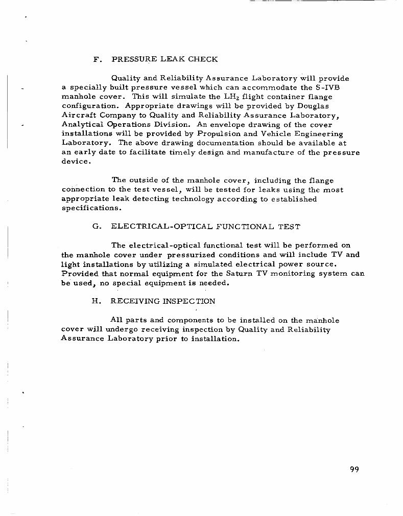
I F. PRESSURE LEAK CHECK
Quality and Reliability Assurance Laboratory will provide
This will simulate the LHz flight container flange - a specially built p ressure vessel which can accommodate the S-IVB
manhole cover. configuration. Appropriate drawings will be provided by Douglas A i r c r a f t Company to Quality and Reliability Assurance Laboratory, Analytical Operations Division. An envelope drawing of the cover installations will be provided by Propulsion and Vehicle Engineering Laboratory. an ear ly date to facilitate timely design and manufacture of the pressure device.
The above drawing documentation should be available at
The outside of the manhole cover, including the flange connection to the tes t vessel, wil l be tested for leaks using the most appropriate leak detecting technology according to established specifications.
G. ELECTRICAL-OPTICAL FUNCTIONAL TEST
The electrical-optical functional test will be performed on the manhole cover under pressurized conditions and will include TV and light installations by utilizing a simulated electrical power source. Provided that normal equipment for the Saturn TV monitoring system can be used, no special equipment is needed.
H. RECEIVING INSPECTION
All par t s and components to be installed on the manhole cover will undergo receiving inspection by Quality and Reliability Assurance Laboratory prior to installation.
99

SECTION XV. GROUND SUPPORT EQUIPMENT
A. ELECTRICAL
The modifications to the S-IVB Stage will require modifications and additions to the electrical support equipment. addition of LOX tank ullage system valves and LH2 continuous vent valves require repatching of the SACTO Beta patch panel -150 and one of the Vertical Checkout Lab patch panels -146 o r -148. This entails revising the patching documents and additional patching on the subject boards.
The
As a result of new Forward Battery # 3 and Forward Buss #3 and their associated E/I, and Load Test switches, a repatching effort is required on -150 and -146 or -148. revised. Al so , a ground load will have to be developed and added to the proposed load tes t box to allow dissipation of the peroxide over-voltage in the new battery.
The patching document must be
Ground power must be provided to Forward Buss # 3 during system test and static firing. sources during tes t and for the heaters when fuel is in the vehicle. Since the heaters a r e thermostatically controlled, switching transients will probably occur on this line and a separate power supply is desirable. There a r e airborne provisions for remote sensing of Forward Buss # 3 which could be used to regulate this supply even though regulation is not a cr i t ical parameter. This will be the most economical and expedient approach.
It is required for the incandescent light
DAG will utilize a source controlled power supply.
The tape programs for the experimental stage at Vertical Checkout Lab and Sacramento must be modified to include new commands and responses associated with the experimental hardware. These changes will be the direct result of alterations in the Test Requirements documents generated in the various airborne sections.
P rogram and patching modifications must be incorporated to The programs verify the experimentally added instrumentation outputs.
for Vertical Checkout Lab and SACTO will require changes and the patching variations can only be determined after re lease of the Test Requirements document and the IP&C List .

The experimental manhold cover, installed at SACTO, wil l
During flight the camera control units and RF Therefore, in order to check out the TV
contain only two light sources and two cameras, one high speed scan and one low speed scan. links will be housed in the IU. cameras and lamp units, it is necessary to provide control units and monitoring devices a s part of the GSE. with H2 dictate that all modules on the stand be either purged and pressurized or be located in a safe area. The Forward Umbilical Room provides a safe a r e a and is l e s s than 100 ft f rom the camera location via cable t r ays . According to MSFC information, the control units must be within 100 f t of the cameras . consisting primarily of GFE equipment. TV Monitor and will consist of the following items:
Safety restrictions associated
A new piece of GSE must be provided It will be called the LH2 Tank
1. Slow speed scan camera control unit - GFE
2. High speed scan camera control unit - GFE
3. Real time monitor capable of presenting either control unit output - G F E (An identical real time monitor is required in the blockhouse - GFE)
4. Video waveshap analyzer (scope) - GFE
5. Video line drive amplifiers (required to re turn video to monitor in the blockhouse during static fire) - G F E
6 . Rack to house video line drive amplified and provide signal switching and power distribution - DAC
7. Two 70-foot cables between control units and cameras - DAC
8. blockhouse monitor - DAC
Two 2000-foot cables between line drive amplifier and
This equipment i s a manual console utilized at SACTO Forward Umbilical Room only.
10 1

B. MECHANICAL
Due to a new tank instrumentation support structure, no modifications will be required to the LH2 tank access kit
C . GOVERNMENT FURNISHED PROPERTY
NASA will furnish to Douglas (Sacramento Facility), on or before September 1, 1965, the following G F E items:
Item Number Quantity De scription
1" 1 High speed (30 FPS) TV camera
2" 1 Low speed (one-half FPS) TV camera
3" 2
4" 1
5" * 1
6" * 1
7" * 2
Lamp unit
Manhole Cover
High Speed Scan Camera Control Unit
Slow Speed Scan Camera Control Unit
Real Time Monitor capable of presenting either control unit output
8" * 1 Video Wave shape Analyzer (Osc ill0 scope)
9" * TBD" * * Video Line Drive Amplifiers (Required to re turn video to Monitor in Blockhouse during Static Firing)
" W i l l be delivered as a package, already tested and ready for installation.
* * W i l l be sent to DAC with an engineer f rom MSFC for the duration of test , then returned to MSFC.
* * * To be determined.
102

DEFINITION OF ABBREVIATIONS
Definition
AM0
ANT
APS
cg
DAC
db
E N
EMC
"g"
GFE
GND
GOX
GSE
m c
MSFC
PAM
P & V E
STC o r SACTO
SSB
Spp/Nrms
SPS
Advanced Material Order
Antenna
Auxially Propulsion System
Center r>t Gravity
Doug1 as Aircraft Company
Decibel
Ele c tronic s As sociated Incorporated
Electr o - Magnetic Capability
Gravity
Government Furnished Equipment
Ground
Gaseous Oxygen
Ground Support Equipment
Hydrogen
S pe cif i c Imprll s e
Liquid Hydrogen
Liquid Oxygen
'Me gac ycl e
Mar shall Space Flight Center
Pulse Amplitude Modulation
Propulsion and Vehicle Engineering Laboratory
Sacramento Test Center o r Sacramento Test Operations
Single Side Band
Signal to Noise ratio
Samples per Second
103

I APPENDIX A
SATURN IB (SA-203) PERFORMANCE CAPABILITY
The purpose of the appendix is to publish the Saturn IB (SA-203) two-stage performance capability for carrying out the liquid hydrogen orbital experiment.
The ground rules used in this study a r e presented below:
1. Launch on an aximuth 72" eas t of north f rom Cape Kennedy, Florida .
2 . Inject into a 100-N. M. c i rcular orbit.
3. The Apollo payload configuration was replaced by the I
generalized nose shape.
4. Place the S-IVB stage in orbit with maximum LH2 onboard after injection based on a tank capacity of 44,393 pounds of hydrogen for an ullage volume of 1. 7 3 per cent.
The weights used in this study a r e presented in Table I and a r e the proposed control weights for SA-203. were taken wi th the concurrence of R-AERO-AA.
The aerodynamic character is t ics
Figure 1 presents the cutoff weight in orbit as a function of second stage lift-off weight for a constant engine mixture ratio of 5. 0, 5. 2 , and 5.4 in the S-IVB stage, respectively.
Figure 2 presents the nominal liquid hydrogen that will be in the tanks of the S-IVB stage at injection as a function of S-IVB jettison weight. the use of S-IVB reserve propellants to account for flight perturbations. The minimum hydrogen in orbit would correspond to the use of all reserve propellant pr ior to injection and a reduction in the liquid hydrogen in the tanks of approximately 300 pounds f rom the values presented.
A nominal flight i s defined to be one which does not require
The following table presents the jettison weight definition.
i ~ ~~
104

Table 1. S-IVB Jettison Weight Definition
.
S-IVB Dry 24,782 lb
Nose Cone Est. 3,200
I. u. 4,650
LH2 Exp. Equipment Est. 1,250
Residuals 1,752
Flight Performance and Propellant Utilization Re serves 1,870
Total 37,504 lb
Figure 3 presents a schematic of the distribution of the propellants in the hydrogen. h y d r og en at inj e c t ion.
Note the definition for nominal liquid
Figure 4 presents the altitude as a function of the range. Note that injection is achieved f rom below the orbit rather than from above the orbit and at a considerably shorter range distance than the normal orbital flight. 750 kg/mz higher than a nominal Saturn IB two-stage vehicle of approximately 3100 kg/mz. reduced through trajectory shaping. 50 pounds of hydrogen for 100 kg/mz reduction.
Also, the maximum dynamic pressure is approxcmately
The maximum dynamic pressure could be A rough tradeoff is approximately
This is very nonlinear.
Figure 5 presents the nominal liquid hydrogen in orbit as a function of time spent at upper mixture ratio for a 5.4/4. 7 program. The analysis is presented for a fixed second stage lift-off weight and an estimated S-IVB jettison weight of 37,504 pounds. between 19,100 and 18,580 pounds as the burn time at the 5.4/1 mixture ratio is increased f rom zero to full duration (246.46 sec). This represents a reduction in hydrogen available a s compared to continuous mixture ratio programs; however, further study should reduce present performance differences .
The liquid hydrogen in orbit var ies
Table I1 presents a typical trajectory provided for engineering analysis .
If the Apollo configuration i s used instead of the standard Saturn IB nose shape, the available hydrogen in orbit will be between 1500 and 2000 pounds less . This is due to approximately a 2800-pound increase in S-IVB jettison weight in orbit and different aerodynamic drag losses.
105

106

' I
1
!-
107

t*
** **
8 5.0 312 lb 5..2 302 lb 5.4 292 lb
5.4/4.7 328 lb
FIGURE 3
SCHEMATIC HYDROGEN TANK
** Nominal hydrogen J in orbit.
1.73% m E x c e s s Hydrogen
'ressuring Gas 245 lb Trapped 447 lb
F.P. & P U R e s e r v e s _.__. - -l 14393 lb Tank Capacity
Mainstage
I
Thrust Decay 25 lb
54# Trapped in Line & Engine
108

109

' I I . .
. . I
-. .
I .
.. I - !
,I
. ...
#
I .
I . - 1
.. I .
I I.
. I .. , .
. I . . .
. I
, I
I . , . I
, 4 ,
I
.
. ..
I
. . ..
110

I m
W 4 I I
a
VI
c v c w I w a c
U " W
> V I . L
U 0 - Z L a . u 7
c A S a
-I W O VVI U- u v
W
0" z- es- -Ir
I- u) D m
I- A I- urn
C I VU7
W A - m
w s- u - w cvi
m o m o m m m m o a o = 3 m I? .n :n 0 0 9 t n m d J W N .........
o e ~ w . m m y m o m - e o m o - . . . . . . . . . . . . . . . 0 0 0 0 2 2 . . . . 00 00
2 0 I-e
00 N N
o o y y o . . . 00000 00000 00000 ccccc 0 0 0 0 0 NNNNN
00
0 0 0 0 0 0 c c 0 0 NN
. .
000000 000000 0 0 0 0 0 0 . . . . . .
r n . a * N O - N ~ I
Y U h
x U
0
o o u * o u u 0 O N N C N CII oor.-o-- m Q o O J Q o . . . . . . .
U
U B c
V a
1 1 1


APPENDIX B
DRAG FORCE, ORBITAL LIFETIME, AND GROUND COMMUNICATIONS VISIBILITY FOR SATURN IB LIQUID
HYDROGEN ORBITAL EXPERIMENT
This appendix contains information in support of MSFC study efforts on the Saturn IB Liquid Hydrogen Orbital Experiment. Three a r e a s are covered: orbital drag forces, orbital lifetime, and ground tracking and data acquisition coverage. The orbiting configuration is shown in Figure 1. 185-km (100-N. M. ) ear th orbit with maximum LHt remaining in the S-IVB stage. cover.age of the propellant behavior.
The S-IVB stage and nose cone a r e inserted into a
The experiment is designed t o provide special TV
A. ORBITAL DRAG FORCES
The predicted drag forces a r e given in the table below for constant angles of attack of 0 degree (nose-on), 6 degrees (per request) and 90 degrees (broadside) and considering a 1969 launch year.
Angle of Attack ‘DA Nominal Maximum Limit (+2m) Force
(de g) (M 1 (N) (1b) (N) (1b) 7
0 70. 5 1.0 0.22 3 .3 6 92.0 1.3 0.29 4.3
90 275. 7 3.9 0.88 12.9
0.73 0. 96 2.9
Uncertainties in extrapolating the atmospheric model with t ime and prediction of the orbital drag coefficient reflect in considerable uncertainty in prediction of the drag force. table represents the possible 2r variation in prediction. force is about 3. 3 t imes the nominal.
The maximum limit force given in the The maximum
B. ORBITAL LIFETIME
If a propulsive venting force is applied to the orbiting vehicle,
If the venting force is applied to keep the propellants seated the orbital lifetime will be dependent on the magnitude and direction of this force. and is, therefore, l a rger than the d r a g force, the orbit altitude will increase during venting, rather than decay.
113

Payload Enve 1 ope
4.19 m
J
S-IVB Stage
C- 6.60 m 10.84 m
\ 3 . 1 5 m
From: Drawing 0787 R-P&VE -AVD
Figure 1. Orbiting Configuration
114

In the absence of venting, a minimum lifetime of about 24 hours would be expected for a nose-on attitude stabilization. This considers an initial orbiting mass of 25,630 kg (56,500 lb) and a propellant boiloff ra te of 420 kg[hr (930 lb/hr), based on information received from R-P&VE-PTF. will nominally be lost after ten hours in orbit. acquires a random tumble, a total minimum lifetime of about 14 hours co.uld be expected.
On the other hand, attitude stabilization If the vehicle then
It may be seen that the actual lifetime will be strongly dependent upon the vehicle attitude history and upon the propellant venting scheme. desired 10-hour lifetime, assuming attitude control for that length of time.
However, there should be no difficulty in achieving a
C. DRAG VARIATION
The orbital drag force and lifetime to be expected will vary with the launch year, since the density of the upper atmosphere var ies with the elevenyear solar activity cycle. will produce changes in the drag forces and lifetim- in the years 1965 - 197 1. Memorandum from Chief, Operations Studies Branch, R -AERO-FO, Drag Force for LH2 Experiment Configuration, August 17, 1964. The atmospheric density used in calculating the orbital drag force and lifetime was obtained f r o m Marshall Technical Paper MTP-AERO-63-2, Earth 's Aerospace Properties f rom 100 to 100,000 km Altitude, January 3, 1964.
The effect of this variation
Complete details on thi-iation can be found in e
D. TRACKING AND COMMUNICATION VISIBILITY
An analysis was made of the ground station tracking, data
Pertinent information is given for planning the required ground
Visibility c i rc les a r e shown for a five-degree elevation angle
acquisition, and possible TV coverage for the orbital flight phase of the missions. network. revolutions. for pr imary existing or planned Manned Space Flight Network and DOD ground stations. planned 85-foot dishes. The coverage time for the three revolutions is given in Table 1. total coverage time above the five-degree elevation. be noted.
Figure 2 shows the ground projections of the first three orbital
The dashed circles represent si tes with existing or
The columns represent acquisition time, loss time, and Several points should
115

116

.
.
I.
u
d
e4 N
0
N m
I. 4
0
;8 18 s o m - m r l N o/m
I.*
u u . .
mrcl u o
m m u m
m u
m u O N
m m m m
m u
117

1. The orbital insertion point occurs at 4 3 3 seconds flight t ime at a ground range of 845 km f rom Cape Kennedy, near the five-degree pickup by the Bermuda site. This yields 4. 2 minutes of Bermuda coverage
revolutions, making it a most desirable location for TV coverage. orbital a s well as immediate post-insertion behavior of the propellant may be observed.
following insertion. Bermuda also covers the flight on two successive t
The
2 . Excellent coverage is supplied by at least four continental North American locations on three successive revolutions. These include Guaymas, White Sands, Houston, and Corpus Christi . one site as a pr imary TV station should be weighed principally on existing equipment to satisfy the required needs, as comparable coverage is provided f r o m all sites. little instrumentation presently is installed either at Guaymas, Corpus Chris t i o r Houston, although future instrumentation is planned.
The selection of any
The White Sands site is already highly instrumented. Very
3 . The Cape Kennedy site provides excellent coverage on three revolutions a s well as 3 0 seconds of data following orbital insertion.
4 . The coverage provided by the 85-foot dish located at Goldstone, California, i s 1 .7 min on revolution 1, 4.5 and 4 . 7 min on revolutions 2 and 3 . other 85-foot dish si tes. The Woomera site covers revolutions 1 and 2 . Although coverage by the Goldstone site is scanty on revolution 1, excellent coverage is provided on the two successive revolutions. As essential facilities a r e already existing at Goldstone and at Woomera, consideration should be given to theiT use.
Intermittent coverage is supplied by the three
118

November 12, 1964 APPROVAL TM X-53158
SATURN IB LIQUID HYDROGEN ORBITAL EXPERIMENT DEFINITION
Compiled By
Advanced Studies Office
The information in this report has been reviewed for security classification. Review of any information concerning Department of Defense or Atomic Energy Commission programs has been made by the MSFC Security Classification Officer. has been determined to be unclassified.
This report, in its entirety,
This document has also been reviewed and approved for technical accuracy.
F. B. CLINE '
Acting Director, Propulsion and Vehicle Engineering Laboratory
*

L
DISTRIBUTION
D IR D r . von B r a u n
D E P -T D r . Rees
D E P -A I M r . Gorman
EX Mi.. Maus Mr . Foster
I I-DIR C 01. O'C onne r
~ I -SE-CH D r . Mrazek Mr . B a r r a z a
I - I / IB C 01. James
Mr . Huff ( 2 ) I M r . P a c e
I -V-S -1VB Mr . Godfrey Mr . Myers
R -DIR M r . We idne r
R -SA Mr . Dannenburg (12)
R -TEST Mr . Heimburg (2)
R -ME , M r . Kuer s
M r . Ches teen
R -QUAL M r . G r a u M r . C e r n y
R -ASTR D r . H a e u s s e r m a n n Mr . Hoberg M r . Powe l l Mr. F i c h t n e r M r . Rei l ly M r . Huggins Mr. Shie lds
R-AERO D r . G e i s s l e r D r . Spea r M r . Teague
R - P & V E - R T M r . Hofues
MS -1P M r . R e m e r
MS -H M r . Akens
KN-DF M r . M o r r i s
LO-DN Mr . Popple M r . von T iesenhausen
MS-IPL M i s s Robinson ( 8 )
R-P&VE-DIR Mr. Cline Mr. Hel lebrand
120

DISTRIBUTION (Concluded)
R-P&VE-P Mr. Paul Mr. McCool Mr. Thompson Mr. Wood Mr. Platt Mr. Swalley (5) Mr. Fuhrmann Mr. Heusinger .
R -P&VE -S Mr. Kroll Mr. Sterett Mr. Verble/Lysaght Mr. Blumrich Mr. Far row Mr. Showers Mr. Fredr ick Mr. Garre t t
R rP& VE -X Mr. Palaoro Mr. Faulkner Mr. Griner
R -P&VE -V Mr. Aberg Mr. Pedigo Mr. Prasthofer Mr. Jacobi Mr. Glover Mr. Schulze Mr. Center Mr. Thrower Mr. Kistler
R -P&VE -M Dr. Lucas Mr. Holmes Mr. Riehl
R-P&VE-A Mr. Goerner Mr. Neighbors Mr. Stein Mr. Johns (20) Mr. Schwartz Mr. De Sanctis
cc-P Mr. Wofford
Scientific and Technical Information Facility Attn: NASA Representatives (2)
P. 0. Box5700 Be the sda, Maryland
(s-AK/RKT)
12 1