NASA TECHNICAL MEMORANOUM TECHNICAL MEMORANOUM NASA TM X-52380 ... (CHM), electron beam machining...
37
NASA TECHNICAL MEMORANOUM NASA TM X-52380 ff 653 Julv 65 FRICTION, WEAR, AND THE INFLUENCE OF SURFACES by Edmond E. Bisson Lewis Research Center Cleveland, Ohio C TECHNICAL PAPER proposed for presentation at Symposium on Surface Integrity sponsored by the American Society of Tool and Manufacturing Engineers Pittsburgh, Pennsylvania, January 24-25, 1968 ' t NATIONAL AERONAUTICS AND SPACE ADMINISTRATION WASHI TON, D.C. 1967 https://ntrs.nasa.gov/search.jsp?R=19680004168 2018-05-20T00:11:34+00:00Z
Transcript of NASA TECHNICAL MEMORANOUM TECHNICAL MEMORANOUM NASA TM X-52380 ... (CHM), electron beam machining...
NASA T E C H N I C A L M E M O R A N O U M
NASA TM X-52380
ff 653 Julv 65
FRICTION, WEAR, AND THE INFLUENCE OF SURFACES
by Edmond E. Bisson
Lewis Research Center Cleveland, Ohio
C TECHNICAL PAPER proposed for presentation at Symposium on Surface Integrity sponsored by the American Society of Tool and Manufacturing Engineers Pittsburgh, Pennsylvania, January 24-25, 1968
'
t
NATIONAL AERONAUTICS AND SPACE ADMINISTRATION WASHI TON, D.C. 1967
https://ntrs.nasa.gov/search.jsp?R=19680004168 2018-05-20T00:11:34+00:00Z
FRICTION, WEAR, AND THE INFLUENCE OF SURFACES
by Edmond E . Bisson
Lewis Research Center Cleveland, Ohio
TECHNICAL PAPER proposed for presentation at
Sympoisum on Surface Integrity sponsored by the American Society of Tool and Manufacturing Engineers
Pittsburgh, Pennsylvania, January 24-25, 1968
NATIONAL AERONAUTICS AND SPACE ADMINISTRATION

FRICTION, WEAR, AND THE INFLUENCE OF SURFACES
by Edmond E?. Bisson
Lewis Research Center National Aeronautics and Space Administration
Cleveland, Ohio 0 INTRODUCTION
9 There are many reasons to believe that the method by which a surface is produced can strongly influence the friction and wear properties of such a surface. Conventional machining involving chip removal, either by single point tools or by grinding wheels, can affect the hardness and structure at the surface. Also, nonconventional material removal processes such as electrochemical machining (ECM) , electrical discharge machining (EDM) , chemical machining (CHM), electron beam machining (EBM) , and laser beam machining (LBM) can influence the nature of the surfaces. It would there- fore appear that both the physical and the chemical nature of the surfaces are strongly dependent on the conditions under which the machining takes place.
It is the objective of this paper to explore how friction and wear are influenced by the surface state. In order to accomplish this objective, a review is made of the fundmental mechanisms involved in both friction and wear. parameters are pointed out. The strong influence of surface contaminants on the friction process is explored in some detail. The various wear proc- esses (adhesive, abrasive, corrosive, and fatigue) are enumerated and two of them are explored. The influence of crystal structure on friction and wear is discussed, and comparisons are made between the hexagonal and cubic structures as well as differences between single crystals and polycrystal- line materials. Finally, the resistance to wear, as influenced by hardness, is discussed. The three principal ways of increasing hardness treated herein are (1) alloying, (2) quenching and tempering, and (3) work harden- ing.
The adhesion theory of friction is discussed, and the important
ADHESION THEORY OF FRICTION
Friction and wear characteristics can best be explained using the adhesion theory of friction. by Merchant in the United States (ref. 1) and by Bowden and Tabor in England (ref. 2 ) . This theory of friction is based on strong adhesive forces between contacting asperties. the asperities come into metallic contact, with resulting high stresses at the true contact area. The true area of contact is so small that, follow- ing elastic deformation, the stress quickly reaches the yield stress of one of the two materials. is obtained at the contact area (some of the surface contaminants are forced out). tively high, "cold welding" can occur at the junction(s) . face relative to the other requires shear at these welded junctions.
This adhesion theory of friction was advanced
As the load is applied (see fig. 1)
Hence, plastic flow occurs and a "cleaning" action
Because local areas are now somewhat clean and the stress is rela- Moving one sur-
1 , TM X-52380

The adhesion theory of f r i c t i o n s t a t e s t h a t the f r i c t i o n force is the first a shear term, the second a
The shear-term is tha t force required t o equal t o the sum of two terms: ploughing or roughness term. shear a t the welded junctions (note that shear may take place i n the junc- t ion itself or adjacent t o it i n e i ther of the two contacting materials). “he ploughing term is t h a t force which resu l t s from displacement of the sof te r of the two metals by an asperi ty of the hard m e t a l . In many in- stances, the ploughing or roughness term is negligible i n comparison with the shew term.
Friction:
F = S + P = Shear + Ploughing = As + A’p
where
A r e a l area of contact
A’ ploughing area
p flow pressure
S shear strength of junction
Contact area :
W - - - Load A = Flow Pressure p
Frict ion coefficient:
F’riction = + A’p- + A’p - W W P W
f = Load
When the ploughing t e r m is negligible,
s Shear strength p Flow pressure
f = - =
( 3 )
(4)
Equation (4) shows t h a t reduction of f r i c t i o n coefficient (and usually, Reduc-
By the use of low shear strength’fi lms (with thicknesses as small as
reduction i n wear) can be obtained i f the r a t i o s/p can be reduced. t ion of the r a t i o resu l t s from low shear strength, high flow pressure, or both. millionths of an inch) on hard base materials, both desirable conditions may be obtained ( r e f . 2 ) . appreciable decrease of the yield strength of the combination. The load w i l l be supported through the f i lm by the hard base material while shear OCCUTS within the s o f t t h i n film. the following types: e t c . ) metals, f l u i d lubricants, so l id lubricants, etc. In fac t , any low shear strength material which i s present as a contaminant on the surface can serve t o reduce f r i c t i o n and, perhaps, t o reduce wear.
Thus, low shear strength is achieved without
These low-shear-strength films can be of oxides, chemical reaction f i l m s (chlorides, sulfides,
2
c
INFLUENCE OF SURFACE COlYTAMINANTS ON FRICTION
It is possible t o show, by use of-monolayers and multilayers, that an extremely th in f i l m of contaminant at the surface can be effect ive i n re - ducing f r ic t ion . Data from reference 2 show that, with a long chain f a t t y acid ( s t ea r i c acid) deposited on stainless s t ee l , the f r i c t i o n coefficient even with a s ingle ' layer ( i * e . , a monolayer) is re la t ive ly low, about 0.1. The f r i c t i o n however rises rapidly as continued runs a re made over the same track. multilayers of 3, 9, or 53 films the f r i c t i o n coefficient starts a t about the same value, 0.1. The greater the number of films, however, the longer it takes t o wear off or displace th i s protective f i lm and consequently the longer the time i n which the f i lm is an effect ive boundary lubricant. The monolayer of s t ea r i c acid has an approximate thickness of 20 angstroms (about It is therefore obvious that any contaminanting f i l m of low shear strength on the surface, even a t thicknesses of the order of m i l - l ionths of an inch, can be effect ive i n reducing f r i c t ion and a l so wear.
These data are shown i n figure 2. With e i ther a monolayer or
inch).
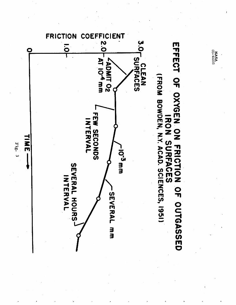
Additional data are available t o show that the effects of contami- nants on f r i c t i o n and wear can be quite appreciable, even though the con- taminanting film may be as th in and poorly adherent as tha t obtained from adsorption of a gas. Figure 3, for example, shows the reduction i n f r i c - t i on obtained by adsorption of oxygen on outgassed i ron surfaces. surfaces have been outgassed i n vacuum (approximately 10-6m Hg) i n order t o clean them. reduced by admission of oxygen gas even though the oxygen pressure i s very low (lo-* mu). creasing the pressure ( i n this case, mm), the f r i c t i o n coefficient is reduced s t i l l more. A t higher pressures (several millimeters of mercury), the f r i c t i o n coefficient is reduced even further. Finally, f igure 3 shows that , i f the surfaces are allowed t o stand for some period of time, the adsorbed oxygen f i l m becomes more complete and the f r i c t ion drops s t i l l further. An important observation from these resul ts , however, is that seizure of the clean metals is prevented by even a t race of oxygen. quite probable that, i n these experiments, the oxygen reacted w i t h the clean i ron surfaces t o form one of the lower oxides of i ron (FeO or FegO4). Both of these oxides a re effective i n preventing seizure of the contacting iron surfaces.
These
These data, from reference 3,show tha t f r i c t i o n i s markedly
If the concentration of oxygen atoms is increased by in-
It is -
The ef fec t of chlorine on the f r i c t ion of i ron surfaces is shown i n
This figure 4. mercury, the f r i c t i o n coefficient drops t o a re la t ive ly low value. e f fec t is nonreversible, as shown i n figure 4 a t the point where the chlo- r ine was frozen out and then readmitted. No appreciable change i n f r i c t i o n occurs under these conditions. In fact , it was necessary t o heat the sur- faces t o a temperature of about 400° C before the resul t ing fi lm was broken up and the f r i c t ion again rose appreciably. Quite probably, with clean i ron surfaces, chemical reaction took place at the surface t o form an i ron chloride fi lm (possibly FeC12). faces t o 400° C probably corresponds t o the temperature required t o decom- pose t h i s film.
As chlorine is admitted a t a pressure of about 1 millimeter of
The indicated necessity t o heat the sur-
The ef fec t of adsorption of hydrogen sulphide gas on the f r i c t i o n of 3
outgassed i ron surfaces is shown i n figure 5; the f r i c t i o n is reduced abruptly and appreciably. duction of f r i c t i o n with hydrogen sulphgde i s not as great as it is with chlorine. Note, however, that t h i s fi lm is much more stable and may be heated t o over 7900 C before decomposition of the f i lm takes place and f r i c t ion r i s e s . It is possible that, with hydrogen sulphide, reaction occurs t o form the i ron sulphide, FeS. The i ron chloride film, FeC12, has a lower shear strength then FeS ( re f . 2) ; t h i s difference i n shear strength would explain the difference i n f r i c t ion coefficient.
Seizure of the surfaces was prevented. The re -
An important point t o be noted here is tha t admission of e i ther oxy- gen, chlorine, or hydrogen sulphide t o the chamber resulted i n prevention of seizure of the metal surfaces. Frequently, the prevention of seizure can be more important than reduction of f r ic t ion , per se. was obtained even though the surface fi lms are extremely thin.
This protection
Buckley (ref. 4) has conducted some experiments with oxygen chemi- These experiments were done i n vacuum (10-l' Torr) sorbed on tungsten.
w i t h tungsten cleaned by electron bombardment. the vacuum chamber i n such a way as t o chemisorb atoms t o various degrees. The surface exposure, i n Torr-seconds, produced oxygen adsorption as shown i n figure 6 (f'rom ref 4). than a monolayer i n thickness until the higher values of surface exposure. Friction data were obtained i n these same experiments at various values of surface exposure. With tungsten i n the clean s t a t e , the f r i c t ion coeffi- cient was 3.0. With oxygen adsorptio2 equal t o approximately a quarter of a monolayer (monolayer thickness = 3 A ) , the f r i c t i o n coefficient drops very markedly from 3.0 t o 1.6, f igure 6. shown i n figure 6 that oxygen adsorption equivalent t o as l i t t l e as three quarters of a monolayer is enough t o reach a steady s t a t e i n the f r i c t ion value, approximately 1.3. These resu l t s again prove the point that the surface need be contaminated t o only a s l igh t degree i n order t o have a marked effect on f r ic t ion .
Oxygen was admitted in to
It i s noted tha t the oxygen adsorption was l e s s
It is apparent from the data
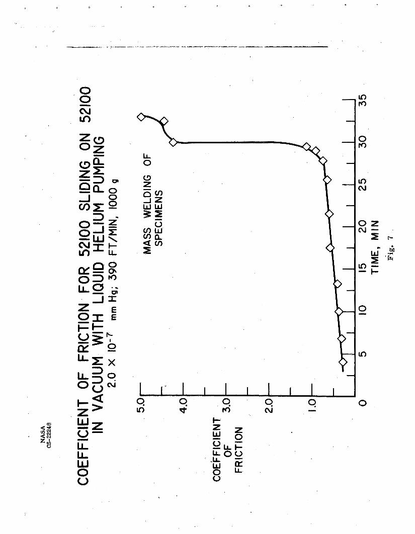
As is well known, i f the surfaces a re suff ic ient ly clean, cold welding ( f r i c t ion welding) of the surfaces may take place when s l iding is attempted. Figure 7 shows some data obtained a t the NASA-Lewis Research Center with the s t e e l 52100 a t a vacuum of lom7 Torr obtained by cryopumping. These data, which a re from reference 5, as well as much of the data on f r i c t ion and wear discussed herein a re reviewed i n some d e t a i l i n Bisson and Anderson ( re f . 6 ) . For the case of the data i n figure 7, a liquid-helium condensing c o i l inside the vacuum chamber condensed the condensible gases such as nitrogen and oxygen. In th i s manner, the authors of reference 5 f e l t that ava i lab i l i ty of oxygen atoms would be markedly reduced from that using ordinary ion pumping. Figure 7 confirms the i r bel ief . The f r i c t i o n coefficient showed a s l igh t increase from its i n i t i a l value of 0.3 t o the value of about 1.0 a t 30 minutes. A t 30 minutes, the f r i c t ion coefficient rose markedly t o a value of about 4.5 a f t e r which it continued r i s ing u n t i l the specimens welded so firmly that the drive motor of the mechanism was s ta l led . The i n i t i a l low f r i c t ion coefficient is believed t o be the r e su l t of the presence of the lower oxides of iron (FeO and Fe 0,). which the f r i c t ion coefficient remained re la t ive ly low f i . e . , l e s s than 1.0) represents the time required t o wear these beneficial oxides *om the
The time i n
4
surface. reform because of the limited availability of oxygen atoms at Hence, cold welding of the surfaces took place.
After the oxide film has been worn from the surface, it could not Torr.
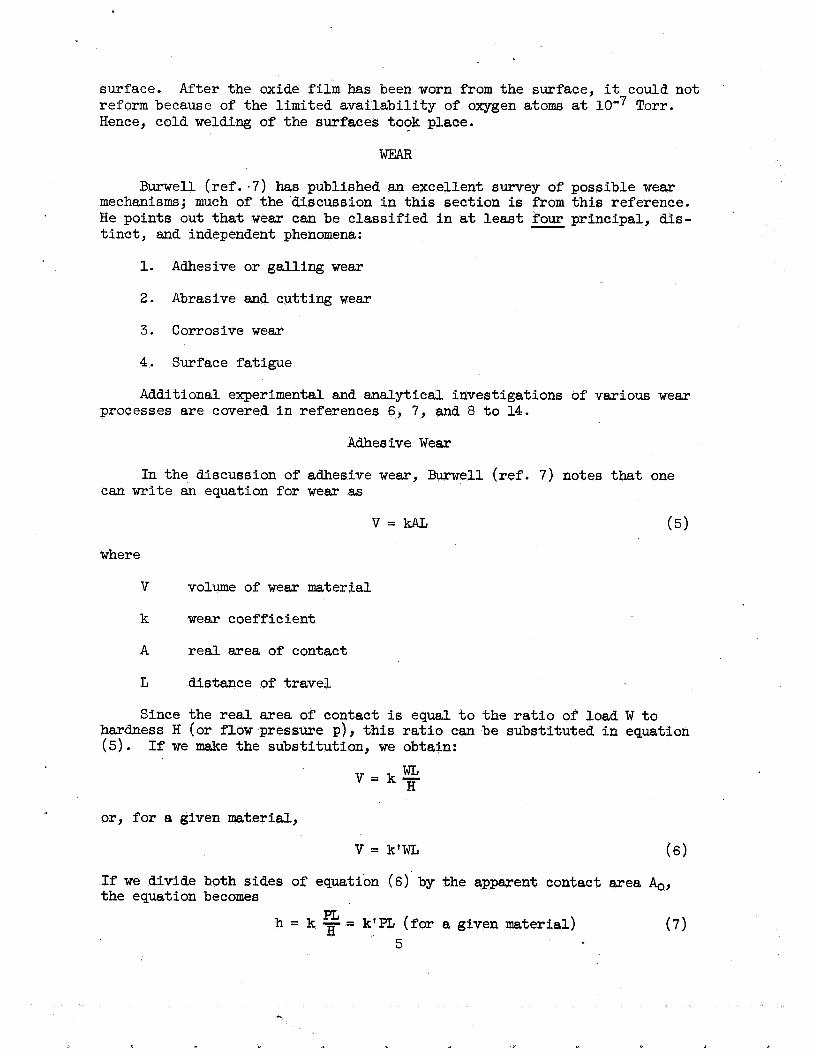
WEAR
Burwell (ref. -7 ) has published an excellent survey of possible wear mechanisms; much of the discussion in this section is from this reference. He points out that wear can be classified in at least four principal, dis- tinct, and independent phenomena:
- 1. Adhesive or galling wear
2. Abrasive and cutting wear
3. Corrosive wear
4. Surface fatigue
Additional experimental and analytical investigations of various wear processes are covered in references 6, 7, and 8 to 14.
Adhesive Wear
In the discussion of adhesive wear, Burwell (ref. 7) notes that one can write an equation for wear as
where
V volume of wear material
k wear coefficient
A real area of contact
L distance of travel
Since the real area of contact is equal to the ratio of load W to hardness H (or flow pressure p) , this ratio can be substituted in equation (5). If we make the substitution, we obtain:
WL V = k- H
or, for a given material,
V = k'WL (6)
If we divide both sides of equation (6) by the apparent contact area &, the equation becomes
(7) PL H h = k - = k'PL (for a given material)
5

where the average depth of w e a r h = V/Ao and the average pressure or design stress P = W/&. In other words, f o r a given material, the adhesive wear coefficient k f is given by the r a t i o
h PL k' = -
Figure 8 shows' the results of some wear experiments conducted by Burwell. ond, t ha t it i s an apparent function of load. Figure 9.gives r e su l t s obtained at the NASA laboratories, which show t h a t w e a r is a l inear func- t ion of load and is completely independent of apparent area of contact or apparent contact s t r e s s .
We see first t h a t wear is a l inea r fhnction of distance and, sec-
The resu l t s of f igures 8 and 9 show that equation (6) is applicable. In other words, k' is a constant character is t ic of the material over a range of speeds and loads.
Burwell continued his experiments a t higher loads and found some pecu- liar resu l t s . A s the load was increased t o a point generally exceeding the range of accepted engineering design, it was found tha t the adhesive wear coefficient k' was no longer constant but increased rapidly with load (that is, w i t h increase i n average compressive s t r e s s ) . i n figure 10 which is a p lo t of the adhesive wear coefficient k' against pressure (average stress). These curves show t h a t the value of wear co- e f f i c i en t i s constant up t o a value of average pressure which is approxi- mately one-third the indentation hardness. Above t h i s pressure, the wear coefficient r i s e s sharply and the curve i s f ina l ly terminated by the onset of large scale welding and seizure. The curve of figure 10(b) is for the same s t e e l as that fo r figure l O ( a ) except that the s t e e l has been hardened t o about twice the Brinel l hardness. The curve fo r the hard s t e e l again shows that the wear coefficient is constant up t o a value of approximately one-third of the identation hardness. It w i l l be noted i n t h i s case, how- ever, tha t the average pressure is appreciably higher because of the higher hardness.
These resu l t s a r e shown
Archard (refs. 11 t o 13) has presented a model of adhesive wear i n which he makes two assumptions: (1) each t i m e asper i t ies come in to contact t o form a junction there is a constant probabili ty that an adhesive frag- ment w i l l be formed, and (2) each fragment is assumed t o be a hemisphere of diameter equal t o the junction diameter. U s i n g these assumptions, he de- velops an equation which is ident ical t 9 B w r w e l l f s with the exception tha t Burwelll,s wear coefficient has been replaced with a wear coefficient k/3 which is different by the factor 1/3. cable i n the assumed case of c i rcular junctions and hemispherical fragments.
This factor is a shape factor appli-
Rabinowicz ( re f . 8) presented a theory of wear involving in t e r f ac i a l energies. In Rabinowicz's theory, which involves stored elastic energy i n a wear par t ic le and adhesional energy acting a t the interface, a trans- ferred par t ic le comes off the surface only i f the e l a s t i c energy is greater than the adhesional energy. U s i n g these assumptions, he derived an equa- t ion which predicts the diameter of wear par t ic les as a function of two materials properties p ( the flow pressure) and Wab the in te r fac ia l energy between materials a and b. Rabinowicz's experiments w i t h various materials
6

(metals and nonmetals) provide some support fo r h i s equations. On the other hand, Tabor has s t a t ed that some research resu l t s i n England and Russia seem t o support the view tha t the formation of wear eagments i s primarily by fatigue of the t ransferre6 material.
Abrasive Wear
Burwell points out t ha t abrasive and cutt ing w e a r me, i n general, the
There a re two general s i tua- same type of damage t o the surface. face plowing or gouging out a sof te r surface. t ions for t h i s type of wear: harder of the two rubbing surfaces (cut t ing w e a r ) ; or ( 2 ) the hard surface i s a th i rd body, generally a small par t ic le of g r i t or abrasive caught be- tween the two surfaces and suf f ic ien t ly harder than these surfaces tha t it abrades e i ther one or both of them (abrasive w e a r ) . strongly influenced by the choice of the combination of materials while abrasive w e a r i s strongly influenced by the type of foreign object (abra- sive) present between the surfaces. formed by chemical reaction with the surrounding atmosphere.
Damage i s accomplished by a hard sur-
(1) the hard surface i n question is the
Cutting wear is
Frequently, the foreign objects are
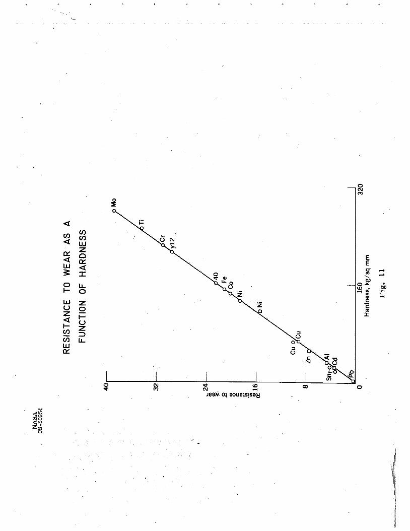
Kruschov and Babichev ( re f . 15) correlate resistance t o wear w i t h hardness of various lftechnically pure metals". f igure 11. mens of 0.41 and 1.1 percent carbon, respectively. these points f a l l on the same curve as for the technically pure metals.
These resu l t s a re shown i n
As noted i n the figure, The points labeled "40" and ' ' ~ 1 2 " a re fo r carbon s t e e l speci-
Spurr and Newcomb ( r e f . 16) have obtained wear r e su l t s as a function of hardness which show agreement with Kruschov and Babichev's resul ts .
Kruschov and Babichev also found ( r e f . 15) tha t alloys gave resu l t s s i m i l a r t o those shown i n figure 11 for technically pure metals. (from r e f . 15) shows general trends of resistance t o wear as a function of three principal ways of increasing hardness: (1) alloying, ( 2 ) quenching and tempering, or (3) work hardening. As indicated, alloying t o increase hardness should r e su l t i n an increase i n the resistance t o wear; similarly quenching and tempering, which resu l t s i n increased hardness, should a l so give increased resistance t o wear. ( s t r a i n hardening), of the surfaces should have no effect since abrasive wear is i t s e l f a work-hardening process (according t o re f . 15). resistance, as measured i n abrasive w e a r t e s t s , is a function of materials i n t h e i r maximum work-hardened s t a t e .
Figure 12
On the other hand, work hardening
Hence wear
In confirmation of the general trends shown i n figure 12, data were
The resu l t s of experiments w i t h four s t ee l s a f t e r quenching obtained w i t h a number of s t ee l s of various compositions and various heat treatments. and tempering at different temperatures a re shown i n figure 13 (*om r e f . 15). chromium, shows appreciably higher wear resistance than do the other three s tee ls . sents the s t e e l "as quenched" or "as-quenched and mildly tempered". each of these s tee ls , points a t lower hardness than the maximum represent different degrees of tempering.
The s t e e l labeled X-12, containing a high percentage of carbon and of
The data a t maximum hardness for each of the four s t ee l s repre- For
7
L
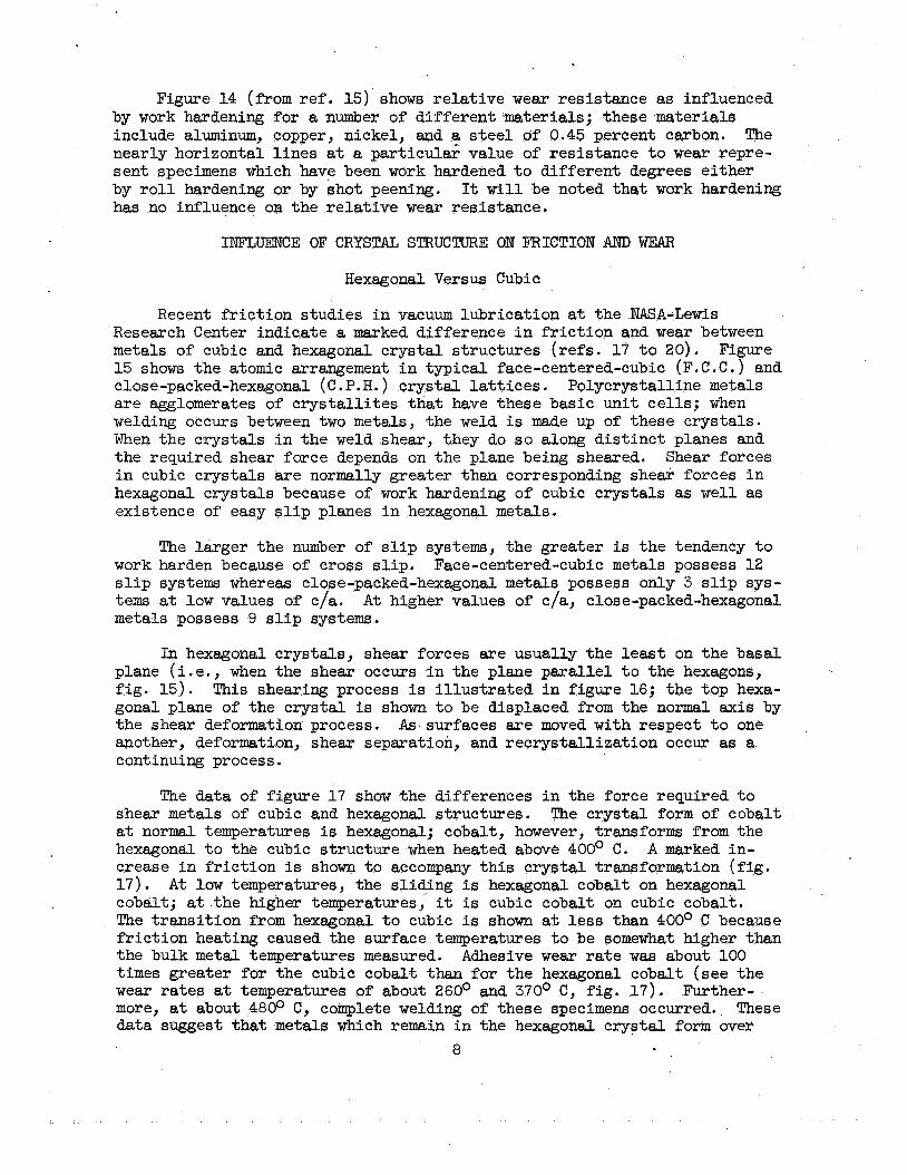
Figure 14 (from ref. 15) shows r e l a t ive wear resistance as influenced by work hardening for a number of d i f fe ren t materials; these materials include aluminum, copper, nickel, and a steel of 0.45 percent carbon. The nearly horizontal l i nes at a par t icular value of resistance t o wear repre- sent specimens which have been work hardened t o different degrees e i ther by roll hardening or by shot peening. has no influence om the r e l a t ive wear resistance.
It w i l l be noted that work hardening
INEZUENCE OF CRYSTAL STRUCTURE ON FRICTION AND WEAR
Hexagonal Versus Cubic
Recent f r i c t ion studies i n vacuum lubrication a t the NASA-Lewis Research Center indicate a marked difference i n f r i c t i o n and wear between metals of cubic and hexagonal c rys ta l structures ( re fs . 17 t o 20). 15 shows the atomic arrangement i n typ ica l face-centered-cubic (F. C. C . ) and close-packed-hexagonal ( C .P.H. ) crys ta l l a t t i c e s , Polycrystalline metals a r e agglomerates of c rys t a l l i t e s that have these basic uni t ce l l s ; when welding occurs between two metals, the weld is made up of these crystals. When the crystals i n the weld shear, they do s o along d i s t inc t planes and the required shear force depends on the plane being sheared. Shear forces i n cubic crystals are normally greater than corresponding shear forces i n hexagonal crystals because of work hardening of cubic crystals as well as existence of easy s l i p planes i n hexagonal metals.
Figure
The larger the number of s l i p systems, the greater is the tendency t o work harden because of cross s l i p . s l i p systems whereas close-packed-hexagonal metals possess only 3 s l i p sys- tems a t low values of c/a. A t higher values of c/a, close-packed-hexagonal metals possess 9 s l i p systems.
Face-centered-cubic metals possess 1 2
In hexagonal crystals, shear forces a re usually the least on the basal plane ( i .e . , when the shear occurs i n the plane para l le l t o the hexagons, f i g . 15). This shearing process is i l l u s t r a t ed i n figure 16; the top hexa- gonal plane of the c rys ta l is shown t o be displaced from the normal axis by the shear deformation process. another, deformation, shear separation, and recrystal l izat ion occur as a continuing process.
As surfaces a re moved with respect t o one
The data of figure 1 7 show the differences i n the force required t o shear metals of cubic and hexagonal structures. a t normal temperatures is hexagonal; cobalt, however, transforms from the hexagonal t o the cubic s t ructure when heated above 400' C. crease i n f r i c t ion is shown t o accompany t h i s c rys ta l transformation ( f ig . 1 7 ) . A t low temperatures, the s l iding is hexagonal cobalt on hexagonal cobalt; a t the higher temperatures, it is cubic cobalt on cubic cobalt. The t rans i t ion from hexagonal t o cubic i s shown a t less than 400° C because f r i c t ion heating caused the surface temperatures t o be somewhat higher than the bulk metal temperatures measured. times greater for the cubic cobalt than for the hexagonal cobalt (see the wear ra tes a t temperatures of about 260° and 370° C, f ig . 17 ) . Further- more, a t about 4800 C y complete welding of these specimens occurred. data suggest t ha t metals which remain i n the hexagonal c rys ta l form over
The crystal form of cobalt
A marked in-
Adhesive wear r a t e was about 100
These
8
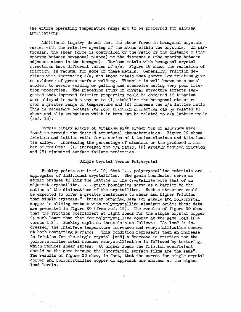
the entire operating temperature range are to be preferred for sliding applications.
Additional inquiry showed that the shear force in hexagonal crystals varies with the relative spacing of the atoms within the crystals. ticular, the shear force is controlled by the ratio of the distance c (the spacing between hexagonal planes) to the distance a (the spacing between adjacent atoms in the hexagon). structures have different values of c/a. Figure 18 shows the variation of friction, in vacuum, for some of these metals. Generally, friction de- clines with increasing c/a, and those metals that showed low friction give no evidence of gross surface welding. subject to severe welding or galling and otherwise having very poor fric- tion properties. The preceding study on crystal structure effects sug- gested that improved friction properties could be obtained if titanium were alloyed in such a way as to (1) stabilize the hexagonal structure over a greater range of temperature and (2) increase the c/a lattice ratio. This is necessary because its poor friction properties can be related to shear and slip mechanisms which in turn can be related to c/a lattice ratio (ref. 18).
In par-
Various metals with hexagonal crystal
Titanium is w e l l known as a metal
Simple binary alloys of titanium with either tin or aluminum were found to provide the desired structural characteristics. friction and lattice ratio for a series of titanium-aluminum and titanium- tin alloys. ber of results: and ( 3 ) minimized surface failure tendencies.
Figure 19 shows
e of aluminum or tin produced a num- Increasing the percent (1) increased the 7 c a ratio, ( 2 ) greatly reduced friction,
Single Crystal Versus Polycrystal
Buckley points out (ref. 19) that I t . . . polycrystalline materials are aggregates of individual crystallites. The grain boundaries serve as atomic bridges to link the lattice of one crystallite with that of an adjacent crystallite. ... grain boundaries serve as a barrier to the motion of the dislocations of the crystallites. be expected to offer a greater resistance to shear and higher friction than single crystals." copper in sliding contact with polycrystalline aluminum oxide; these data are presented in figure 20 (f'rom ref. 19). The results of figure 20 show that the friction coefficient at light loads for the single crystal copper is much lower than that for polycrystalline copper at the same load (0.4 versus 1.2). creased, the interface temperature increases and recrystallization occurs at both contacting surfaces. in friction for the single crystal [and] a decrease in friction for the polycrystalline metal because recrystallization is followed by texturing, which reduces shear stress. should be the same because the interfacial surface films are the same". The results of figure 20 show, in fact, that the curves for single crystal copper and polycrystalline copper do approach one another at the higher load levels.
Such a structure could
Buckley obtained data for single and polycrystal
Buckley explains these data as follows: "As load is in-
This condition represents then an increase
At higher loads the friction coefficient
9

X-ray Laue patterns of the crystal surfaces after the maximum load runs of figure 20 indicated recrystallization and texturing of the copper surfaces for both single crystal and polycrystalline copper. -
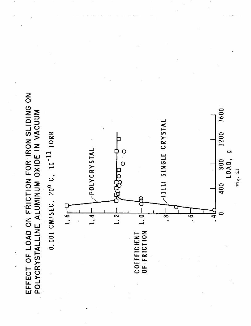
The results with polycrystalline copper and single crystal copper Nickel is a
Both of
were also checked with two other metals, nickel and iron. face centered cubic metal while iron is a body-centered-cubic metal. results with these two metals are shown in figures 21 and 22. these figures show that initially, there is a marked difference in fric- tion between the single crystal and the polycrystalline material. Poly- crystalline nickel, at light loads, shows a friction coefficient of 1.6 as compared to the single crystal coefficient of 0.4. With iron, the poly- crystalline friction coefficient is 1.6 at light loads while the single crystal coefficient is 0.8. Again, as was the case with copper, an in- crease in load results in a decrease in friction for the polycrystalline material and an increase in friction for the single crystal until, at high loads, the friction for the two different materials is essentially the same. As before, these data are explained on the basis of recrystalliza- tion and texturing (orientation) at the interface.
The
It would appear that any method of production which results in re- crystallization and texturing of the surface, may appreciably change the friction and wear properties of a given material. Such changes in fric- tion and wear would be expected whether the surface production methods involve conventional machining methods or nonconventional material removal methods.
Buckley (ref. 20) indicated that there is some correlation between recrystallization temperatures for metals and their sliding friction be- havior. ture for various metals from the literature with their friction behavior. These data are presented in table I. which equivalent friction coefficients were obtained for the single crys- tal and the polycrystalline metals as well as the approximate recrystalli- zation temperature from literature. These data show an apparent correla- tion.
In accordance, he attempts to correlate recrystallization tempera-
This table presents the loads at
CONCLUDING REMARKS
It would appear from the discussion in this paper that any process for producing a surface which results in contamination of that surface (with oxides or reaction products) should produce an appreciable difference in friction and wear properties. faces which changes the crystal size and orientation of crystallites at the surface may appreciably change the friction and wear properties of such materials. The evidence regarding the influence of work hardening of the surfaces is not as clear cut. searchers, that work hardening does not influence the basic resistance to "abrasive wear". adhesive wear could be appreciably influenced by the condition of the sur- faces with respect to hardness and with respect to any contaminating film. Since friction and adhesive wear are strongly influenced by the yield
Also, any method of production of sur-
It would appear, from the Russian re-
It should be pointed out, however, that the resistance to -
10
strength of the welded asperties, it should be expected that any change in yield strength of the material at the surface should have an &ppreciable influence on both friction and wear.
REFERENCES
1. Merchant, M. E.: The Mechanism of Static Friction. J. Appl. F’hys., vol. 11, no. 3, Mas. 1940, p. 230.
2, Bowden, F. P. and Tabor, D.: The Friction and Lubrication of Solids. Clarendon Press (Oxford), 1950 (revised 1954).
3. Bowden, F. P.: The Influence of Surface Films on the Friction, Adhesion, and Surface Damage of Solids. Ann. New Yosk Acad. Sei., vol. 53, art. 4, June 27, 1951, pp. 805-823.
4. Buckley, D. H.: Influence of Chemisorbed Films of Various Gases on Proposed NASA Technical Note. Adhesion and Friction of Tungsten.
5. Buckley, D. H., Swikert, M. A. and Johnson, R. L.: Friction, Wear, and Evaporation Rates of Various Materials in Vacuum to mm Hg. ASLE Trans. vol. 5, no. 1, Apr. 1962, pp. 8-23.
6. Bisson, E. E. and Anderson, W. J.: Advanced Bearing Technology. NASA SP-38, 1964.
7. Burwell, J. T., Jr.: Survey of Possible Wear Mechanisms. Wear, vol. 1, no. 2, Oct. 1957, pp. 119-141.
8. Rabinowicz, E.: Friction and Wear of Materials. John Wiley and Sons, Inc., 1965.
9. Fkuschov, M. M. and Babichev, M. A.: An Investigation of the Wear of Metals and Alloys by Rubbing on a Abrasive Surface. Wear in Machinery. Vol. 11, ASME, 1956.
Friction and
lO.Kragelskii, I. V.: Friction and Wear. Butterworths, Inc., 1965.
ll.Archard, J. F. and Hirst, W.: An Examination of Mild Wear Process. Proc. Roy. SOC., Ser. A, vol. 238, no. 1215, Jan. 29, 1957, pp. 515- 529.
12 .&chard, J. F. and Hirst, W. : The Wear of Metals Under Unlubricated Conditions. Proc. Roy. SOC., Ser. A, vol. 236, no. 1206, Aug. 2, 1956, pp. 397-410.
13.Archard, J. F. : Contact and Rubbing of Flat Surfaces. J. Appl. Phys., vol. 24, no. 8, Aug. 1953, pp. 981-988.
14.Hirst, W. and Lancaster, J. K.: Surface Film Formation and Metallic Wear. J. Appl. Phys., vol. 27, no. 9, Sept. 1956, pp. 1057-1065.
11
15.Kruschov, M. M., and Babichev, M. A. : The Effect of Heat Treatment and Work Hardening on the Resistance to Abrasive Wear of Some Alloy Steels. Friction and Wear in Machinery. Vol. 19, ASME, 1965.
16.Spurr, R. T. and Newcomb, T. P. : The Friction and Wear of Various
Institution Mechanical Engineers Pro- Materials Sliding Against Unlubricated Surfaces of Different Ty-pes and Degrees of Roughness. ceedings, Conference on Lubrication and Wear, London, 1957.
17.Buckley, D. H. and Johnson, R. L.: Fkiction and Wear of Hexagonal Metals and Alloys as Related to Structure and Lattice Parameters in Vacuum to Millimeters Mercury. ASU Trans., vol. 9, no. 2, Apr. 1966, pp. 121-135.
18.Buckley, D. H.: Influence of Crystal Orientation on Friction Charac- teristics of Titanium Single Crystals in Vacuum. 1965.
NASA TN D-2988,
19.Buckley, D. H.: The Influence of the Atomic Nature of Crystalline Materials on Friction. ASLE-ASME Lubrication Conference, Chicago, Ill., Oct. 17-19, 1967.
ZO.Buckley, D. H.: Effect of Recrystallization on Friction Properties of Some Metals in Single-Crystal and Polycrystalline Form. D-4143, 1967.
NASA TN
12

3t o - iE I-
cn
0 -I
Z
cn w as: 3 I-
aL w a, z W I-
z 0 I-
N 1 1
I- cn t as: 0 w w
a n a
n a
a
- a
a
-
as: 0 LL
w 2
I-
0
w w W
n
a m
-
3 cn I- Z w o LL LL w 0 o z 0 I- o as: LL
I- z w -I
> 3 (31 w
- -
- -
a -
z 0 c N A e
II
a n -
d
c w a
=E
0 0 0.0 0 0 O V I , r C \ O O O ; I r n W r h O * r n
M
0 0 cv 0 0 m 0 0 0 0 Ln 111
0
Ln m
0 0 VI, m

LL 0
I- o a
CI 4 0
t. >
I
d
a w

n (r U
t
J 0 z 0 z
a
n - 0 a 0 - a a W I- a
FR I CTlON COEFFl C I ENT N 0 e
0 0 0 I .

I
Coefficient of friction
0 c -I c) D u, u, m U
H iu 0 Z
v) c iu “rl D c) m
0 “rl
c) X 0 iu Z m
r -

I
FRICTION COEFFICIENT
w cu c#J
1 1 0 0 0
I

OXYGEN ADSORPTION AND FRICTION FOR TUNGSTEN SLIDING ON TUNGSTEN
O X Y G E N A T O M A D S OR P T l O N , ( A T O M S I C M ~ )
C O E F F I C I E N T OF F R I C T I O N
1.
O X Y G E N A D S O R P T I O N
3.0 F R I C T I O N A S A F U N C T I O N OF O X Y G E N S U R F A C E C O V E R A G E
2 . 5
R I D E R (100) P L A N E D I S K (100) P L A N E 0 .001 C M I S E C , 5 0 G M 20' C, 1 0 ' l o T O R R
2 . 0
6 A N D l O ~ l O - ~ 7 1 . 5
1.01 I I I I I I 0 . 4 . a 1 . 2 1. 6 2.. D . *,2. 4 x 1 0 ' 5
S U R F A C E E X P O S U R E ( T O R R - S E C ) ' Fig. 6
0 '0 cu Ln
-
LJ -2 V- - CL L L IJJ 0 V
n
I I' I I I I I I I I 9 9 9 0 - 9
N 9 M lo d=
I

u a
d o v ,
rl
E 0
0 *
i 0
I

0 rc
rr)
‘0 0
UnOH M3d - ‘NI n3 ‘31QU UQ3M
I I- O o +
0 dr
0 0 cu
0

6 X e cv
LL 0 u)
d z 0 t- V Z
LL
- cn cn W w t- cn
0 rn 4
E 0 a 0
cn a 2! 3 v) v) e a,
6 1d n
W W
CY W >
a
a
\ I-
w a Y
a
w CY
4 4

LI
a
a
a
u)
Y 0 c- w 0 z a
z OL 0
Q z s
a
c.
+
" \ acr,
o w Z L \
\ w -
\

J w QL
I I I I I 0 0 0 0 0 0 00 a d cv
0 0 0 I-4
I
0

z I- o z 3
0
LL
a a
a
cn
w o z I- cn
W W I- v,
I 0 a
I I I I I I I
0 0 0 0 0 0 . 00 \o a cv
0 0 00
cv


I a
I-

- W t v ,
W . O 0
0
x 00
111 /
0 0
E 0 LL
Z 0
0
LL
LL 0
I- Z W 0 -LL LL W -0 0
F: E
.I) -
\ -1
z0 u) 3 0 E a
a > I-
2) 2) 0
> a
W O mI- 7 W
cp I
Vi
/ z 0
f' d d G O
:<a 0 0 4
x x I X w w
I I I 0 N 00 d
0 .

cn I #- W r:
a
I z 0 (3
% W I:
a
a
cn 3 0 fY
>
- a LL 0
0 1 I - 0 e f
-- I - ’ .I..I)
I
e I, -
0 - ( D
a, - a 0 -
0” a a
- I-
We 0 - I-
oot - -.I
- 1 I I I

x 3 ,z I- I-
- a - oe 0 LL
LLJ 0 I- )I- 4: I
-
n a * z
Z 0 -
I 0 1
6 1 0 ' I
m " !
I 0
1 \ I C
00 - - 0
a a ml

LL 0 I- z w -
l a 0 LL
z 0 I- o LL
- -
a o w
I* c - * -
- z 111,
0 I 0 rl
a
c
.
0 0 0
0 0 00
0 ru
3 3 N
3
E - - w
Z Q o w
b
. H
c z 70 w - -I- t)o
ku,
OLL 00
n~
w
e e
0 0 cv e
ET
0 2
0 0 d
0

v)
LL 0
I
rn 0 1- a
ac CIL
zi d 01 a.
C
c L!
3
33 3
A
c v)
t. QL 0
a
\ 0-
0 0
H ' H H l-4 0 0
c z 70 w - -!- 00 -- :E W O L 00
0 0 d cv
0 0 0 cv
0 0
H
0 0 00
0 0 d
0