NASA TECHNICAL MEMORANDUM - ntrs.nasa.gov · PDF filevenient form. For example, by the ......
16
NASA TECHNICAL NASA TM X-62,290 MEMORANDUM CN x z VARIABLE CONDUCTANCE HEAT PIPES FROM THE LABORATORY TO SPACE J. P. Kirkpatrick Ames Research Center Moffett Field, Calif. 94035 (NASA-TM-X-62290) VARIABLE CONDUCTANCE \N73-2897 'HEAT PIPES FROM THE LABORATORY TO SPACE (NASA) 16 BHC $3.00 CSCL 208. Unclas G3/33 10410 July 1973 Reproduced by NATIONAL TECHNICAL INFORMATION SERVICE US Department of Commerce Springlield, VA. 22151 https://ntrs.nasa.gov/search.jsp?R=19730020185 2018-05-25T07:39:33+00:00Z
Transcript of NASA TECHNICAL MEMORANDUM - ntrs.nasa.gov · PDF filevenient form. For example, by the ......
NASA TECHNICAL NASA TM X-62,290
MEMORANDUM
CN
x
z
VARIABLE CONDUCTANCE HEAT PIPES
FROM THE LABORATORY TO SPACE
J. P. Kirkpatrick
Ames Research CenterMoffett Field, Calif. 94035
(NASA-TM-X-62290) VARIABLE CONDUCTANCE \N73-2897'HEAT PIPES FROM THE LABORATORY TO SPACE(NASA) 16 BHC $3.00 CSCL 208.
Unclas
G3/33 10410
July 1973
Reproduced by
NATIONAL TECHNICALINFORMATION SERVICE
US Department of CommerceSpringlield, VA. 22151
https://ntrs.nasa.gov/search.jsp?R=19730020185 2018-05-25T07:39:33+00:00Z
-1-
J.P.K.VARIABLE CONDUCTANCE HEAT PIPESFROM THE LABORATORY TO SPACE
J. P. KirkpatrickAmes Research Center, NASA
Moffett Field, California, 94035 USA
ABSTRACT
Heat pipes have been developed which can be used as (1) a variable conduc-tance link between a heat source and sink which provides temperaturestability; (2) a feedback control mechanism that acts to directly maintain
the source at a constant temperature; (3) or as a thermal diode that allows
heat to be transferred in one direction only. To establish flight levelconfidence in these basic control techniques, the Ames Heat Pipe Experiment(AHPE) was launched in August 1972 and the Advanced Thermal Control FlightExperiment (ATFE) is scheduled for launch in May 1973. The major effortsof the technology development, initial flight results of the AHPE, and
ground test data of the ATFE are discussed.
INTRODUCTION
Heat pipes allow the thermal designer to regulate the transfer of thermalenergy in ways that previously did not exist, at least not in such a con-venient form. For example, by the use of various techniques, a heat pipe
can be used as (1) a variable conductance link between a heat source and
sink, which provides temperature stability; (2) a feedback control mechanism
that acts to directly maintain the source at a constant temperature; (3) or
as a thermal diode that allows heat to be transferred in one direction only.
Many spacecraft applications require close temperature control while
internal power dissipations and/or external heat fluxes vary widely, thus
making variable conductance capabilities desirable, if not necessary. In
1969, the National Aeronautics and Space Administration (NASA) initiated a
technology development program for such techniques at Ames Research Center.
This paper discusses the major development efforts of this on-going program.
As progress was made in the laboratory, it became evident that flight level
confidence must also be established. Consequently, the Ames Heat PipeExperiment was developed for the Orbiting Astronomical Observatory (OAO-C),which was placed in earth orbit in August 1972; the Advanced Thermal
Control Flight Experiment was developed and qualified for flight aboard the
Applications Technology Satellite (ATS-F), which is scheduled for launch in
May 1974. This paper reflects the experience gained in moving variable
conductance techniques from the laboratory to space. It also presents
initial flight results for the Ames Heat Pipe Experiment and ground test
data for the Advanced Thermal Control Flight Experiment.
TECHNOLOGY DEVELOPMENT
Several researchers, both in the United States and Europe, have contributed
significantly to the development of basic control mechanisms. However,
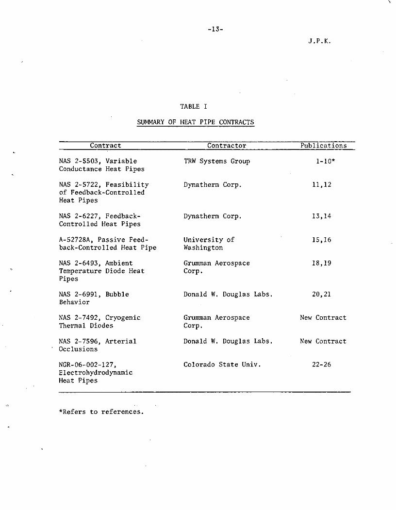
only the efforts of the Ames Research Center and its contractors (Table I)
are summarized below.

-2-
J.P.K.
Variable Conductance
Initial efforts were directed toward identifying various techniques by whicha heat pipe could be made to operate as a variable conductance link betweena heat source and sink. Three promising techniques were identified andcarried to various stages of development: gas control, excess liquid con-trol, and vapor control.
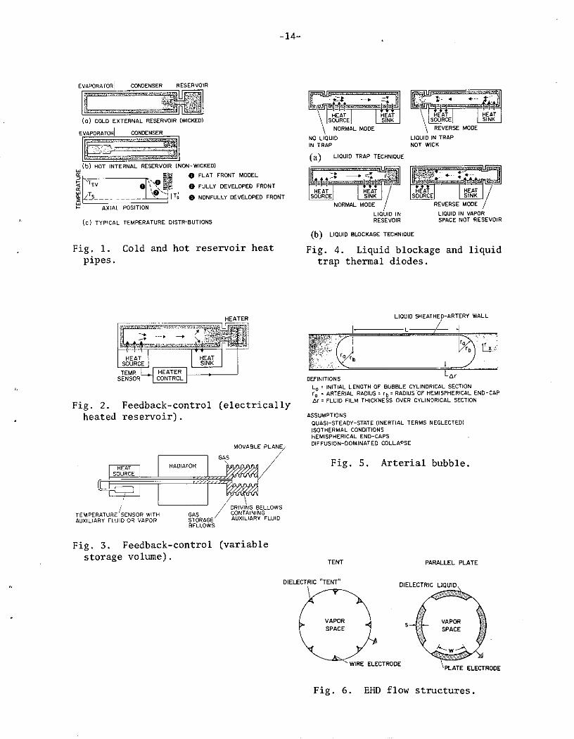
The use of noncondensing gas to vary the effective condenser length wasinvestigated in the greatest detail. Basically, the technique involves theaddition of a fixed quantity of gas which does not condense at the lowesttemperatures experienced by the heat pipe. The gas, since it cannot bewicked back to the evaporator region, is swept to the end of the condenserand any reservoir volume that has been provided, forming a gas plug (Fig. 1).This gas plug acts as a diffusion barrier to the flowing vapor and effec-tively "shuts off" that portion of the condenser it fills. Consequently,variation in the length of this gas plug in response to changes in evap-orator and/or reservoir temperature represents a variation in activecondenser length and hence in heat transfer from the system.
Since the operating temperature of a gas-controlled heat pipe varies withreservoir temperature, the reservoir should be placed in one of two loca-tions where its temperature is most easily determined. In one case (coldreservoir), the reservoir is located at the end of the condenser so thatits temperature depends on the effective space temperature (Ts) and fluc-tuates with variations in thermal environment (Fig. l(a)). The second case(hot reservoir) thermally couples the reservoir to the evaporator so thatits temperature range corresponds to the control range of the heat pipe(Fig. 1(b)).
There is a fundamental difference in these two approaches. The cold externalreservoir must be wicked since vapor diffusing through the gas will condensein the reservoir and be lost to the wicking system. The partial pressureof vapor in the reservoir will then be the vapor pressure corresponding toits temperature. On the other hand, the hot internal reservoir must not bewicked since its vapor pressure would then be equal to that in the evap-orator (i.e., the total pressure) and it could contain no gas. Withoutwicking, the partial pressure of vapor in the reservoir is established bydiffusion to and from the reservoir entrance (e.g., the end of the condenser)and hence, at steady-state conditions, it corresponds to the temperature atthis point (T'; Fig. l(c)).
Ames Research Center was offered an opportunity to fly a variable conduc-tance heat pipe on the OAO-C shortly after the initiation of its study ofcontrol techniques. Based on the understanding of the OAO-C applicationand the state of the art at that time, a hot, nonwicked gas-controlled heatpipe was chosen.1'2 Consequently, much of the succeeding technology devel-opment 3 was focused on this technique. The steady-state and transientperformance was characterized for hot reservoir heat pipes4 ,5 and, for gas-loaded heat pipes in general, the heat and mass transfer in the vicinity ofthe vapor-gas front was analyzed6 and computerized. 7 The use of noncon-densing gas to aid start-up from the frozen state and the freeze-out ofvapor diffusing into the inactive, cold portion of the condenser was alsoinvestigated analytically and experimentally.5,8
Using the above technology, a cold, wicked reservoir heat pipe/radiator wasdeveloped in response to a potential thermal problem on the Apollo 16 Lunar
-3-
J.P.K.
Surface Magnetometer (LSM).9 Although it was eventually determined thatthe heat pipe/radiator was not required for adequate functioning of theLSM, its design, fabrication, and testing in a period of only 6 weeks demon-strated that technology had been developed for using variable conductanceheat pipes in important thermal control applications.
The use of excess liquid to effectively vary the active condenser length byblockage similar to gas control was explored in less detail.3 Vapor controlis achieved by interrupting or throttling the flow of vapor between theevaporator and condenser sections, giving rise to a pressure differentialbetween the two regions and thus a temperature difference. Using thisprinciple of vapor modulation, the overall temperature drop can be variedfor any given axial heat-transfer rate (i.e., variable conductance) in amanner that is relatively insensitive to variations in heat sink conditions.The development of scaling laws for accelerated life testing was alsoconsidered.10
Feedback Control
There are characteristics of a passive gas-controlled heat pipe that limitits flexibility and control capability. For example, the vapor temperatureinside the active portion of the pipe is stabilized by the gas controlmechanism. Therefore, since an ideal variable conductance heat pipe with aconstant temperature reservoir of infinite size can only maintain a constantvapor temperature, the heat source temperature will always vary proportion-ally to the product of its power dissipation and thermal resistance into thevapor. Secondly, variations in reservoir temperature for any reason wasshown in the preceding section to also affect controllability. A thirdproblem might be the generation of gas which would tend to shift the controlrange upward. Finally, the desired control range or thermal operatingenvironment of the heat pipe may not be fully known at the time the fixedquantity of control gas must be added.
To avoid these limitations or potential problems, the heat source temperaturemust be controlled directly with a feedback mechanism that moves the positionof the vapor/gas front beyond that provided by passive control. Two prom-ising methods of achieving this feedback control were identified by afeasibility study.11
The most promising method was the use of a wicked reservoir, electricallyheated by a controller that senses the temperature of the heat sourcedirectly. 12 Such a system is shown schematically in Fig. 2. Increasingthe reservoir temperature increases the vapor pressure in the reservoir,thus reducing the partial pressure of noncondensing gas (the total pressuremust remain equal to the evaporator vapor pressure). The gas displacedfrom the reservoir then causes a shift in the vapor/gas front toward theevaporator. Likewise, a reduction in reservoir temperature allows more gasto recede into the reservoir to replace the mass of working vapor diminishedby the lower vapor pressure. The application of this method generallyrequires a careful transient analysis to obtain satisfactory response timeswith minimum heater power.13 Feedback control using the heated reservoirwas chosen for the ATFE. 14
There exists some applications in which electrical power is not availableand a second method of feedback control must be used. This concept uses avariable volume reservoir (Fig. 3). An increase in heat source temperaturecauses the expansion of an auxiliary bellows which, in turn, expands the
-4-
J.P.K.
reservoir. The fluctuation in reservoir volume then allows gas to beremoved from or forced into the condenser section and moves the vapor/gasfront. Although, identified in the feasibility study, this concept hasonly recently been verified experimentally.1 5 ,16 The mechanical and oper-ational complexity of the variable volume concept requires that furtheroptimization be conducted before attractive performance is achieved. (Thisoptimization is currently in progress at Ames Research Center.17 )
Thermal Diode
An increasing number of applications in both the ambient and cryogenictemperature ranges requires efficient heat transfer in one direction, butcan tolerate very little, if any, heat transfer in the reverse direction.Many concepts have been advanced to achieve this diode effect. 1 8 Amongthese are the use of noncondensing gas to block the vapor space, freezingor allowing the working fluid to become supercritical, trapping the liquidto dry out all or part of the wick, the use of excess working fluid to block
the vapor space, and mechanical methods such as check valves.
Although designed as a gas-controlled variable conductance heat ipe, theLSM heat pipe/radiator operated as a diode during the lunar day. Storingnoncondensing gas, however, generally requires significantly larger reser-voirs than for excess working fluid. Volumetric sensitivity of the gas totemperature variations is also much greater. Letting the fluid freeze or gosupercritical depends, of course, on a close match between fluid propertiesand the temperature levels that will actually be experienced by the diode,after accounting for conduction along the pipe, etc. Freezing of the work-
ing fluid was considered for the LSM application, but was discarded after
some interesting temperature excursions were identified.9
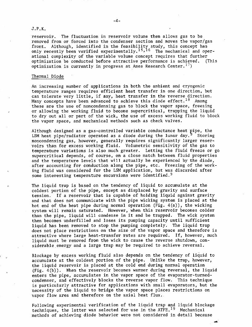
The liquid trap is based on the tendency of liquid to accumulate at the
coldest portion of the pipe, except as displaced by gravity and surfacetension. If a reservoir that is capable of holding liquid against gravity
and that does not communicate with the pipe wicking system is placed at the
hot end of the heat pipe during normal operation (Fig. 4(a)), the wickingsystem will remain saturated. However, when this reservoir becomes colder
than the pipe, liquid will condense in it and be trapped. The wick systemthen becomes underfilled and loses its pumping capacity until sufficientliquid has been removed to stop the pumping completely. The liquid trap
does not place restrictions on the size of the vapor space and therefore isattractive where large heat-transfer rates are required. If, however, muchliquid must be removed from the wick to cause the reverse shutdown, con-siderable.energy and a large trap may be required to achieve reversal.
Blockage by excess working fluid also depends on the tendency of liquid to
accumulate at the coldest portion of the pipe. Unlike the trap, however,the liquid reservoir is placed at the cold end during normal operation(Fig. 4(b)). When the reservoir becomes warmer during reversal, the liquid
enters the pipe, accumulates in the vapor space of the evaporator-turned-
condenser, and effectively blocks the reverse vapor flow. This techniqueis particularly attractive for applications with small evaporators, but the
necessity of the liquid to bridge the vapor space places restrictions on
vapor flow area and therefore on the axial heat flux..
Following experimental verification of the liquid trap and liquid blockage
techniques, the latter was selected for use in the ATFE. 1 9 Mechanicalmethods of achieving diode behavior were not considered in detail because

-5-
J.P.K.
of the additional complexity and possible reduced reliability of movingparts.
Hydrodynamics
A potential priming problem exists in any heat pipe that uses a composite orarterial wicking system. The most universal problem is the trapping ofnoncondensible gas bubbles in the liquid-sheathed wick (Fig. 5). Impuritiesand material incompatibility often are sources of sufficient gas to causethis difficulty. In the case of gas-controlled heat pipes, the control gasitself represents the problem.source. There appear to be two alternativesfor using composite or arterial wicks in the presence of gas: (1) understandthe behavior of gas bubbles in sufficient detail to design the heat pipe(choice of fluid, gas, and wick configuration) so that the bubble can bedissolved quickly enough to achieve satisfactory performance or (2) design awicking system that will not allow bubbles to become trapped.
The lifetime of an arterial bubble under diverse conditions has beenanalytically and experimentally determined for stagnant conditions usingexperimentally determined diffusivity and solubility measurements. 2 0,2 1
Efforts to extend this understanding to the dynamic conditions inside anoperating heat pipe and to accomplish the second alternative are currentlyin progress.
An interesting alternative to arterial wicks for dielectric fluids is theaxial movement of the liquid by electrohydrodynamic (EHD) forces. 2 2 - 2 6 Anexample of an EHD flow structure is shown in Fig. 6. The EHD polarizationforce establishes hydrostatic equilibrium similar to capillary forces,which is unbalanced by the evaporation and condensation. The liquid flowscontinuously to reestablish this equilibrium. EHD offers some potentialadvantages such as heat-transfer enhancement by the electric field, reliablevoltage priming, bubble ejection from the axial flow path, greatly reducedliquid fraction factor for the returning condensate, and voltage control asa variable conductance technique. EHD may also be useful in simply priminglarge arterial heat pipes. These potential advantages, however, must beweighed against the greater complexity of an EHD heat pipe and the require-ment for a high-voltage power supply. Further, the long-term stability ofdielectric fluids in the presence of corona or intermittent arcing must beconsidered.
SPACE-FLIGHT EXPERIMENTS
Ames Heat Pipe Experiment (AHPE)
The AHPE is providing, for the first time, an opportunity to evaluate theperformance of a gas-loaded variable conductance heat pipe in the spaceenvironment. In addition, the effectiveness of a variable conductance heatpipe in maintaining temperature stability in a specific engineering appli-cation is being demonstrated.
System Description
The AHPE controls the temperature of the spacecraft's On-Board-Processor(OBP) by regulating the flow of heat from the back of the OBP equipmentshelf to a space radiator (Fig. 7). As in many spacecraft applications,both the power dissipated by the OBP and the external heat flux incidenton the radiator vary significantly. A detailed description of these
-6-
J.P.K.
conditions and their impact on the design of the AHPE has been previouslyreported.1 The major design features of the AHPE are summarized below:
Working fluid: methanolControl gas: heliumPipe material: stainless steelReservoir: Hot, nonwickedWick system: filled arteryMaximum heat load: 22 WRadiator sink temperature (design values): -190 C (max.), -520 C (min.)Control range: 15.50 to 21.00 CRadiator: Alzak coated aluminum (a/E = 0.17/0.75)Reservoir/condenser volume ratio: 10:1
Orbital Performance
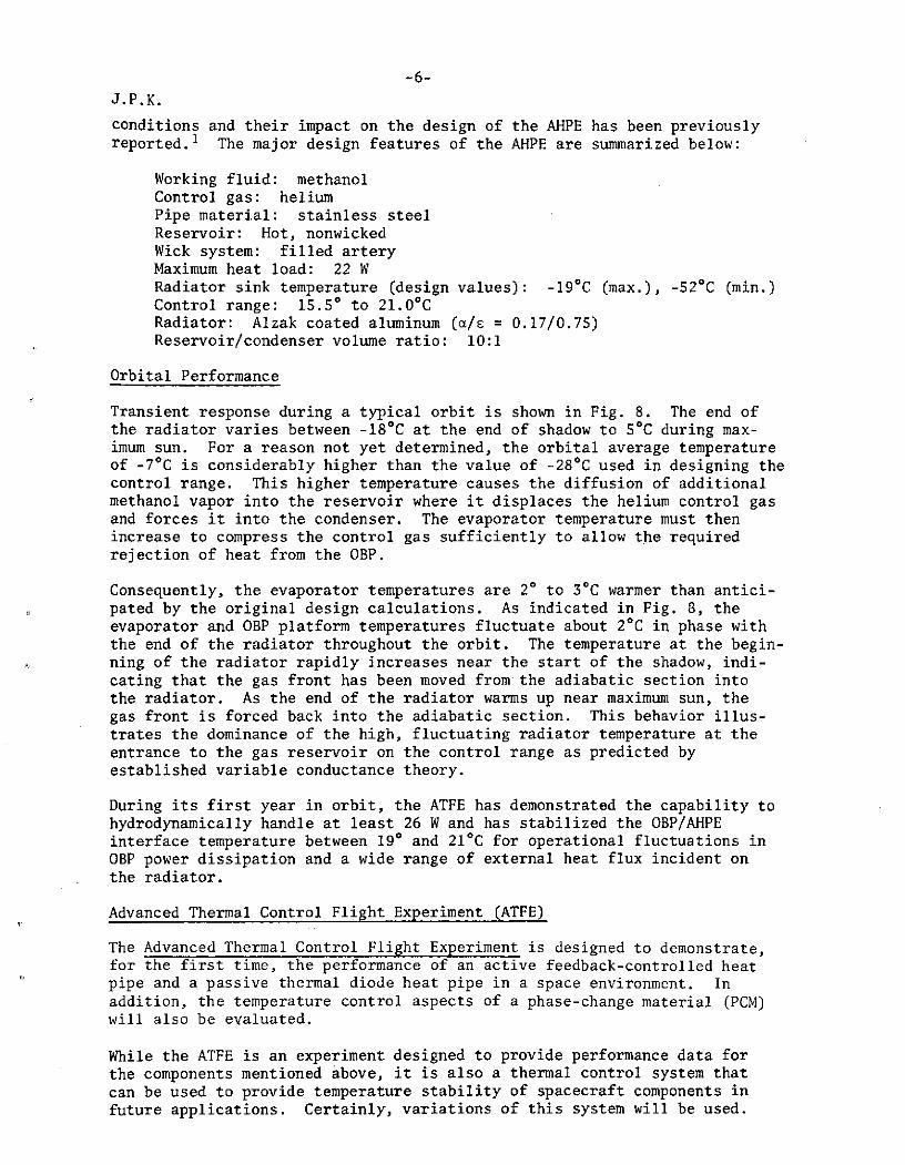
Transient response during a typical orbit is shown in Fig. 8. The end ofthe radiator varies between -180 C at the end of shadow to 50 C during max-imum sun. For a reason not yet determined, the orbital average temperatureof -70C is considerably higher than the value of -280C used in designing thecontrol range. This higher temperature causes the diffusion of additionalmethanol vapor into the reservoir where it displaces the helium control gasand forces it into the condenser. The evaporator temperature must thenincrease to compress the control gas sufficiently to allow the requiredrejection of heat from the OBP.
Consequently, the evaporator temperatures are 20 to 30 C warmer than antici-pated by the original design calculations. As indicated in Fig. 8, theevaporator and OBP platform temperatures fluctuate about 20 C in phase withthe end of the radiator throughout the orbit. The temperature at the begin-ning of the radiator rapidly increases near the start of the shadow, indi-cating that the gas front has been moved from the adiabatic section intothe radiator. As the end of the radiator warms up near maximum sun, thegas front is forced back into the adiabatic section. This behavior illus-trates the dominance of the high, fluctuating radiator temperature at theentrance to the gas reservoir on the control range as predicted byestablished variable conductance theory.
During its first year in orbit, the ATFE has demonstrated the capability tohydrodynamically handle at least 26 W and has stabilized the OBP/AHPEinterface temperature between 190 and 210C for operational fluctuations inOBP power dissipation and a wide range of external heat flux incident onthe radiator.
Advanced Thermal Control Flight Experiment (ATFE)
The Advanced Thermal Control Flight Experiment is designed to demonstrate,for the first time, the performance of an active feedback-controlled heatpipe and a passive thermal diode heat pipe in a space environment. Inaddition, the temperature control aspects of a phase-change material (PCM)will also be evaluated.
While the ATFE is an experiment designed to provide performance data forthe components mentioned above, it is also a thermal control system thatcan be used to provide temperature stability of spacecraft components infuture applications. Certainly, variations of this system will be used.
-7-J.P.K.
System Description
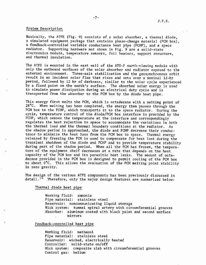
Basically, the ATFE (Fig. 9) consists of a solar absorber, a thermal diode,a simulated equipment package that contains phase-change material (PCM box),a feedback-controlled variable conductance heat pipe (FCHP), and a spaceradiator. Supporting hardware not shown in Fig. 9 are a solid-stateelectronics module, temperature sensors, foil heaters, support structure,and thermal insulation.
The ATFE is mounted in the east wall of the ATS-F earth-viewing module withonly the outboard surfaces of the solar absorber and radiator exposed to theexternal environment. Three-axis stabilization and the geosynchronous orbitresult in an incident solar flux that rises and sets over a nominal 12-hrperiod, followed by 12 hr of darkness, similar to the solar cycle experiencedby a fixed point on the earth's surface. The absorbed solar energy is usedto simulate power dissipation during an electrical duty cycle and istransported from the absorber to the PCM box by the diode heat pipe.
This energy first melts the PCM, which is octadecane with a melting point of280C. When melting has been completed, the energy then passes through thePCM box to the FCHP, which transports it to the space radiator. During thecycle, temperature control of the diode/PCM box interface is provided by theFCHP, which senses the temperature at the interface and correspondinglyregulates the heat rejection to space to accommodate the variations in boththe thermal load and the thermal boundary conditions at the radiator. Asthe shadow period is approached, the diode and FCHP decrease their conduc-tance to minimize the heat loss from the PCM box to space. Thermal energyreleased by freezing the PCM is used to compensate for heat lost during thetransient shutdown of the diode and FCHP and to provide temperature stabilityduring part of the shadow period. When all the PCM has frozen, the tempera-ture of the equipment shelf decreases at a rate that depends on the heatcapacity of the PCM box and its parasitic heat leaks. The amount of octa-decane provided in the PCM box is designed to permit cooling of the PCM boxto about OOC. This allows the evaluation of the PCM melting point stabilityin zero gravity.
The design of the various ATFE components has been previously discussed indetail.11 Therefore, only the major design features are summarized below:
Thermal diode heat pipe
Working fluid: ammoniaPipe material: stainless steelReservoir: noncommunicating liquid storageWick system: tunnel spiral artery with circumferential groovesAbsorber: aluminum coated with black paint and second surface
mirrors
Feedback-controlled heat pipe
Working fluid: methanolPipe material: stainless steelReservoir: wicked, electrically heatedController: solid-state on/offWick system: composite slab with circumferential groovesControl gas: helium

-8-
J.P.K.
Reservoir/condenser volume ratio: 5:1Radiator: segmented aluminum coated with second surface mirrors
PCM Box
PCM: practical grade octadecaneMatrix: expanded aluminum honeycombVoid space: 15% total internal volumeLiquid management: correctly sized holesEnergy storage: 26 W-hr
System Thermal Performance During Acceptance Testing
The ATFE has been qualified and accepted for flight in accordance with theATS-F environmental test specifications for experiments which requiredelectromagnetic interference, functional, leak, vibration, storage tempera-ture, hot and cold soak, and thermal/vacuum testing.
The performance of the ATFE under simulated orbital conditions for variousoperational modes was of major interest and therefore comprised a signifi-cant portion of the testing program. The ATFE was mounted in a panelrepresenting the east wall of the spacecraft. This panel formed one sideof a box that radiatively simulated the internal cavity of the spacecraft.The temperature of this box was then controlled to the desired spacecrafttemperature. Foil heaters bonded to the inboard sides of the absorber andradiator were used to simulate absorbed solar energy. Voltage to theheaters was automatically stepped at 20-min intervals to the correct levelcorresponding to the solar energy cycle. Throughout the entire orbit, theabsorber and radiator viewed the cold chamber walls.
Typical Transient Performance with Feedback Control
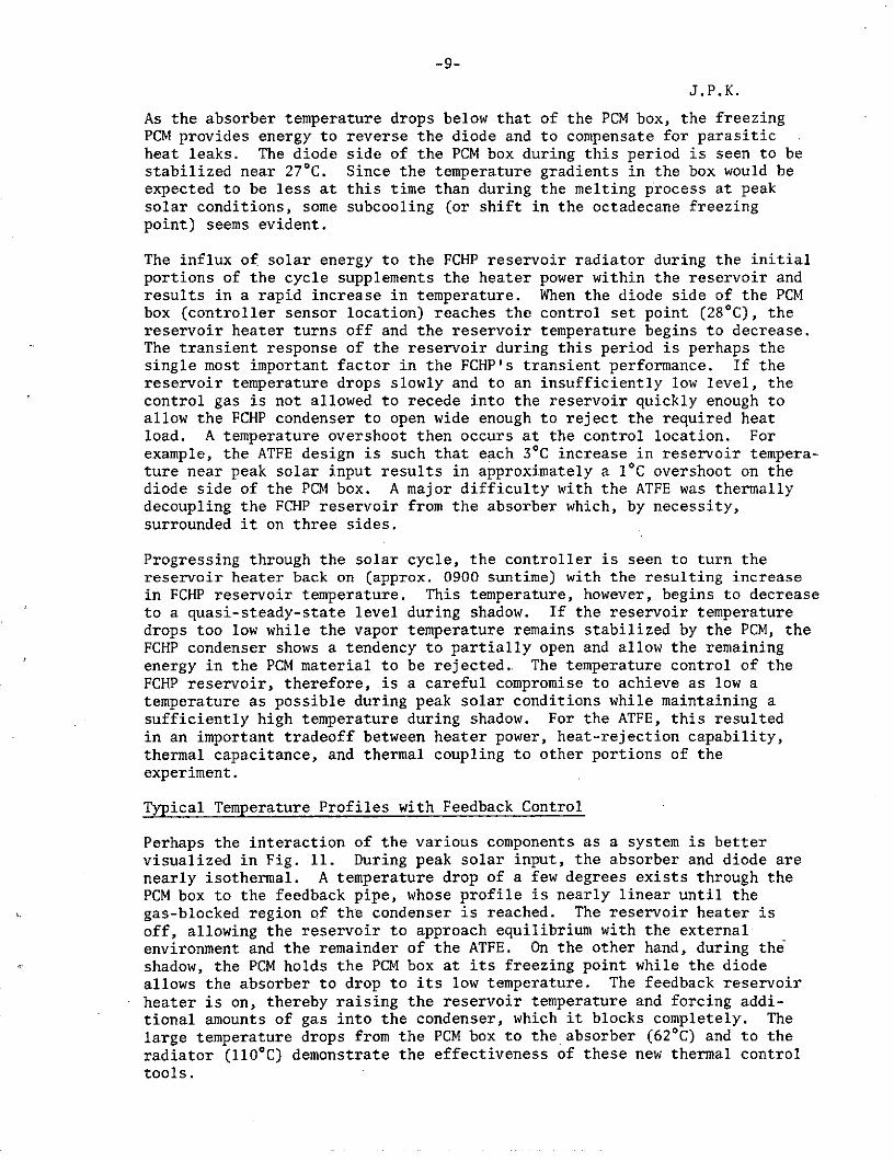
The ATFE exhibited the characteristic transient performance shown in Fig. 10.As the ATFE moved from the end of the shadowed period into sunlight, theabsorber quickly rose from -600 C to a maximum of 32.50 C near maximum solarinput. It then decreased in temperature as the sun "went down" until thediode completed its reversal. The absorber remained at a plateau of -390 Cuntil all the PCM had frozen and the PCM box dropped in temperature. Someinconsistency in the temperature level of this plateau was encountered withboth the qualification and flight units. On some occasions, temperaturelevels as high as -190C have existed after an apparent partial reversal ofthe diode. Another interesting phenomenon has been a tendency of theabsorber to show a slight warming trend just prior to complete freezing ofthe PCM. It appears that the extreme sensitivity of the fluid inventoryremaining in the noncommunicating diode reservoir to temperature profilesalong the pipe may be the major factor causing the inconsistent behavior.
The PCM box also increased rapidly in temperature as the diode began trans-ferring energy to it early in the solar cycle. It then became stabilizednear 280C (octadecane melting point), with a sufficient temperature grad-ient (approximately 20C) from the diode to FCHP side to assure that all thePCM was melted. It should be recognized that the temperature stability ofthe system can be no better than the temperature gradients required in thePCM box to assure melting and freezing of the PCM. For the ATFE, thisminimum range is approximately 260 to 300C.
-9-
J.P.K.
As the absorber temperature drops below that of the PCM box, the freezingPCM provides energy to reverse the diode and to compensate for parasiticheat leaks. The diode side of the PCM box during this period is seen to bestabilized near 270 C. Since the temperature gradients in the box would beexpected to be less at this time than during the melting process at peaksolar conditions, some subcooling (or shift in the octadecane freezingpoint) seems evident.
The influx of solar energy to the FCHP reservoir radiator during the initialportions of the cycle supplements the heater power within the reservoir andresults in a rapid increase in temperature. When the diode side of the PCMbox (controller sensor location) reaches the control set point (280C), thereservoir heater turns off and the reservoir temperature begins to decrease.The transient response of the reservoir during this period is perhaps thesingle most important factor in the FCHP's transient performance. If thereservoir temperature drops slowly and to an insufficiently low level, thecontrol gas is not allowed to recede into the reservoir quickly enough toallow the FCHP condenser to open wide enough to reject the required heatload. A temperature overshoot then occurs at the control location. Forexample, the ATFE design is such that each 30C increase in reservoir tempera-ture near peak solar input results in approximately a 10C overshoot on thediode side of the PCM box. A major difficulty with the ATFE was thermallydecoupling the FCHP reservoir from the absorber which, by necessity,surrounded it on three sides.
Progressing through the solar cycle, the controller is seen to turn thereservoir heater back on (approx. 0900 suntime) with the resulting increasein FCHP reservoir temperature. This temperature, however, begins to decreaseto a quasi-steady-state level during shadow. If the reservoir temperaturedrops too low while the vapor temperature remains stabilized by the PCM, theFCHP condenser shows a tendency to partially open and allow the remainingenergy in the PCM material to be rejected. The temperature control of theFCHP reservoir, therefore, is a careful compromise to achieve as low atemperature as possible during peak solar conditions while maintaining asufficiently high temperature during shadow. For the ATFE, this resultedin an important tradeoff between heater power, heat-rejection capability,thermal capacitance, and thermal coupling to other portions of theexperiment.
Typical Temperature Profiles with Feedback Control
Perhaps the interaction of the various components as a system is bettervisualized in Fig. 11. During peak solar input, the absorber and diode arenearly isothermal. A temperature drop of a few degrees exists through thePCM box to the feedback pipe, whose profile is nearly linear until thegas-blocked region of the condenser is reached. The reservoir heater isoff, allowing the reservoir to approach equilibrium with the externalenvironment and the remainder of the ATFE. On the other hand, during theshadow, the PCM holds the PCM box at its freezing point while the diodeallows the absorber to drop to its low temperature. The feedback reservoirheater is on, thereby raising the reservoir temperature and forcing addi-tional amounts of gas into the condenser, which it blocks completely. Thelarge temperature drops from the PCM box to the absorber (620 C) and to theradiator (110 0 C) demonstrate the effectiveness of these new thermal controltools.
-10-
J.P.K.
SUMMARY
Ames Research Center has been engaged in an extensive program of heat pipedevelopment with particular emphasis on basic control mechanisms. Early
efforts were focused on gas control and resulted in the Ames Heat PipeExperiment on the OAO-C spacecraft. Orbital performance of the AHPE has
been in accordance with established theory. Additional development is
required for other promising variable conductance techniques such as vaporcontrol and condenser blockage by excess fluid.
Two methods of feedback control have been established. The use of a variable
volume reservoir requires further optimization, while the use of electricalheaters to vary the reservoir temperature has shown impressive performance.This latter method has been selected for the ATFE scheduled for launch
aboard the ATS-F spacecraft in May 1974.
Several concepts for achieving thermal diode behavior have been explored and
verified experimentally. One of these - liquid blockage by excess fluid -has also been incorporated into the ATFE. Considerable work remains to bedone in developing the various techniques for potential applications,particularly in the cryogenic temperature range.
The reliable priming of arterial wicking systems in the presence of noncon-
densing gas is a major concern, especially where gas has been intentionallyadded for control purposes. Therefore, an understanding of the static and
dynamic behavior of bubbles in arteries is being developed. An alternativeis the development of arterial wicks that do not trap bubbles. Electro-
hydrodynamic (EHD) pumping appears to be a feasible substitute and/or primingaid for capillary-pumped arteries in special applications. However, EHDheat pipes are still in the early stages of development.
Based on the established fundamental understanding of basic control mech-
anisms, the orbital performance of the AHPE, and the impressive performance
of the ATFE during flight acceptance tests, it can be said with some
confidence that variable conductance heat pipes are moving from thelaboratory to space.
-11-
J.P.K.
REFERENCES
1J.P. Kirkpatrick and B.D. Marcus: A Variable Conductance Heat PipeFlight Experiment. AIAA Paper 71-411, April 1971 (also in AIAA Progress inAstronautics and Aeronautics: Fundamentals of Spacecraft Thermal Design,Vol. 29).
2B.D. Marcus: Ames Heat Pipe Experiment Document. NASA CR-114413,Jan. 1972.
3B.D. Marcus: Theory and Design of Variable Conductance Heat Pipes.NASA CR-2018, April 1971.
4B.D. Marcus and G.L. Fleischman: Steady-State and Transient Per-formance of Hot Reservoir Gas-Controlled Heat Pipes. ASME Paper 70-HT/SpT-11, June 1970.
5D.K. Edwards, G.L. Fleischman, and B.D. Marcus: Theory and Design ofVariable Conductance Heat Pipes: Steady State and Transient Performance.NASA CR-114530, Dec. 1972.
6D.K. Edwards and B.D. Marcus: Heat and Mass Transfer in the Vicinityof the Vapor-Gas Front in Gas Loaded Heat Pipe. ASME Paper 71-WA/Ht-29,Nov. 1971.
7D.K. Edwards, G.L. Fleischman, and B.D. Marcus: User's Manual for theTRW Gaspipe Program. NASA CR-114306, April 1971.
8B.D. Marcus, G.L. Fleischman, and D.K. Edwards: Diffusion Freezeoutin Gas Loaded Heat Pipes. ASME Paper 72-WA/Ht-33, Nov. 1972.
9J.P. Kirkpatrick and B.D. Marcus: A Variable Conductance Radiator forthe Lunar Surface Magnetometer. AIAA Paper 72-271, April 1972 (also inAIAA Progress in Astronautics and Aeronautics: Thermal Control and Radiation,Vol. 31).
1 0W.T. Anderson, Jr.: Hydrogen Evolution in Nickel-Water Heat Pipes.AIAA Paper 73-726, July 1973.
1 1W.B. Bienert: Study to Evaluate the Feasibility of a Feedback Con-trolled Variable Conductance Heat Pipe. NASA CR-73475, Sept. 1970.
12W.B. Bienert, P.J. Brennan, and J.P. Kirkpatrick: Feedback-Controlled
Variable Conductance Heat Pipes. AIAA Paper 71-421, April 1971 (also in
AIAA Progress in Astronautics and Aeronautics: Fundamentals of SpacecraftThermal Design, Vol.. 29).
1 3W.B. Bienert and P.J. Brennan: Transient Performance of ElectricalFeedback-Controlled Variable Conductance Heat Pipes. ASME Paper 71-AV-27,July 1971.
14J.P. Kirkpatrick and P.J. Brennan: The Advanced Thermal ControlFlight Experiment. AIAA Paper 73-757, July 1973.
. 1 5C.A. Depew et al.: Construction and Testing of a Gas-Loaded Passive-Control Variable Conductance Heat Pipe. NASA CR-114597, June 1973.
-12-
J.P.K.16C.A. Depew, W.J. Sauerbrey, and B.A. Benson: Construction and Testing
of a Gas-Loaded, Passive-Control, Variable-Conductance Heat Pipe. AIAAPaper 73-727, July 1973.
17K.R. Schlitt: Design and Testing of a Passive Feedback ControlledVariable Conductance Heat Pipe. Proceedings of the Ist International HeatPipe Conference, Stuttgart, Germany, Oct. 1973.
18B. Swerdling and R. Kosson: Design, Fabrication, and Testing of aThermal Diode. NASA CR-114526, Dec. 1972.
19B. Swerdling et al.: Development of a Thermal Diode for the AdvancedThermal Control Flight Experiment. AIAA Paper 72-260, April 1972 (also inAIAA Progress in Astronautics and Aeronautics: Thermal Control andRadiation, Vol. 31).
2 0E.W. Saaski: Investigation of Bubbles in Arterial Heat Pipes. NASACR-114531, Dec. 1972.
2 1E.W. Saaski: Gas Occlusions in Arterial Heat Pipes. AIAA Paper73-724, July 1973.
22T.B. Jones: The Feasibility of Electrohydrodynamic Heat Pipes.Research Rept. 1, NASA CR-114392, Oct. 1971.
23T.B. Jones and M.P. Perry: Entrainment in Electrohydrodynamic HeatPipes. NASA CR-114499, Aug. 1972.
24T.B. Jones and M.P. Perry: Experiments with an ElectrohydrodynamicHeat Pipe. NASA CR-114498, Sept. 1972.
25T.B. Jones: An Electrohydrodynamic Heat Pipe. ASME Paper 72-WA/Ht-35,Nov. 1972.
26T.B. Jones: Electrohydrodynamic Heat Pipes. Intern. J. Heat MassTransfer 16, (1973), pp. 1048-1095.
-13-
J.P.K.
TABLE I
SUMMARY OF HEAT PIPE CONTRACTS
Contract Contractor Publications
NAS 2-5503, Variable TRW Systems Group 1-10*Conductance Heat Pipes
NAS 2-5722, Feasibility Dynatherm Corp. 11,12of Feedback-ControlledHeat Pipes
NAS 2-6227, Feedback- Dynatherm Corp. 13,14Controlled Heat Pipes
A-52728A, Passive Feed- University of 15,16back-Controlled Heat Pipe Washington
NAS 2-6493, Ambient Grumman Aerospace 18,19Temperature Diode Heat Corp.Pipes
NAS 2-6991, Bubble Donald W. Douglas Labs. 20,21Behavior
NAS 2-7492, Cryogenic Grumman Aerospace New ContractThermal Diodes Corp.
NAS 2-7596, Arterial Donald W. Douglas Labs. New ContractOcclusions
NGR-06-002-127, Colorado State Univ. 22-26ElectrohydrodynamicHeat Pipes
*Refers to references.
-14-
EVAPORATOR I CONDENSER RESERVOIR
HEAT HEAT A HEAT
(O) COLD EXTERNAL RESERVOIR (WICKED) SOURCE SINK SOURCE SINK
EVAPORATORI CONDENSER NORMAL MODE REVERSE MODE
NO LIQUID LIQUID IN TRAPIN TRAP NOT WICK
(a) LIQUID TRAP TECHNIQUE
(b) HOT INTERNAL RESERVOIR (NON-WICKED)%I O FLAT FRONT MODEL +-
EV O O FULLY DEVELOPED FRONT
T HEAT HEAT HEATs L l6Ts 0 NONFULLY DEVELOPED FRONT SOURCE SINK SOURC SINK
AXIAL POSITION NORMAL MODE / REVERSE MODE
LIQUID IN LIQUID IN VAPOR
(C) TYPICAL TEMPERATURE DISTRIBUTIONS RESEVOIR SPACE NOT RESEVOIR
(b) LIQUID BLOCKAGE TECHNIQUE
Fig. 1. Cold and hot reservoir heat Fig. 4. Liquid blockage and liquidpipes. trap thermal diodes.
HEATER LIQUID SHEATHED-ARTERY WALL
HEAT HEAT r bSOURCE SINK
TEMP HEATERSENSOR CONTROL DEFINITIONS Ar
Lo = INITIAL LENGTH OF BUBBLE CYLINDRICAL SECTIONra = ARTERIAL RADIUS = rb= RADIUS OF HEMISPHERICAL END-CAP
Fig. 2. Feedback-control (electrically Ar= FLUID FILM THICKNESS OVER CYLINDRICAL SECTION
heated reservoir). ASSUMPTIONSQUASI-STEADY-STATE (INERTIAL TERMS NEGLECTED)ISOTHERMAL CONDITIONSHEMISPHERICAL END-CAPS
MOVABLE PLANE DIFFUSION-DOMINATED COLLAPSE
GAS
HEAT RADIATOR Fig. 5. Arterial bubble.SOURCE
SDRIVING BELLOWSTEMPERATURE SENSOR WITH GAS CONTAININGAUXILIARY FLUID OR VAPOR STORAGE AUXILIARY FLUID
BELLOWS
Fig. 3. Feedback-control (variable
storage volume). TENT PARALLEL PLATE
DIELECTRIC "TENT" DIELECTRIC LIQUID
VAPOR VAPORSPACE )SPACE
WIRE ELECTRODEPLATE ELECTRODE
Fig. 6. EHD flow structures.

-15-
GAS/VAPOR INTERFACE
SKIN / OUT RADIATOR
EVAPORATOR
GASRESERVOIR DIN GIN GIN GIN PLATFORM
ELECTRONICS
Fig. 7. Ames heat pipe experiment.
o = RADIATOR/FIRST FINo = EVAPORATOR/UPSTREAM END
S= EVAPORATOR/DOWNSTREAM END
oC oF v = RADIATOR/LAST FIN 7o = OBP PLATFORM
100-
30 - ORBITAL PERIOD = 100 min' .
25- 80-
20 -15- 60- 110 - - 1
5 - 40- 20 0-
-5 20 3-10
-15 1 SOLAR ABSORBER 7 FCHP CONDENSER SECTION0 - 2 GAS RESERVOIR 8 FCHP EVAPORATOR SECTION
-20 SHADOW 26 3 CONTROL HEATER 9 THERMAL DIODE HEAT PIPE-25 . 4 GAS/VAPOR INTERFACE 10 DIODE EVAPORATOR SECTION
-30 -20 5 RADIATOR 11 DIODE CONDENSER SECTION_30, _ , ,,, _ , , , , 6 FEEDBACK CONTROLLED 12 PHASE CHANGE MATERIAL (PCM) BOX
6300 6500 6700 7000 7200 7400 HEAT PIPE (FCHP) 13 LIQUID RESERVOIR
SPACECRAFT SET TIME
Fig. 9. Advanced thermal controlFig. 8. Typical AHPE orbital data. flight experiment.
40 - 40 --- DIODE HEAT
O ABSORBER PIPE
20 - O PCM DIODE SIDE 20 / - FEED BACKHEAT PIPE
O FCHP RESERVOIR00 PEAK SOLAR
O ~. FCHP FIN NO. I 0 CONDITIONS
20 I 0 SHADOW-20 - -20 -
I-2O IoJ -40 - -40 - DIODE
X TRANSPORT"i SECTION
-60 -60PCM BOX RADIATOR RESERVIOR
-80 - -80 CHRAP RTRESERVIORABSORBERSECTION FEED TUBE
0-100 -IO0 1 i
0 600 1200 1800 2400 0 20 40 60 80 100 120 140
SUNTIME, hours AXIAL LOCATIONS, cm
Fig. 10. Typical ATFE transient Fig. 11. Typical ATFE temperatureperformance. profile.