Nasa tech briefs ksk 11495, simplified model of duct flow
29
John F. Kennedy Space Center Kennedy Space Center, Florida 32899 Technical Support Package Simplified Model of Duct Flow NASA Tech Briefs KSC-11495 NI\S/\ National Aeronautics and Space Administration
-
Upload
julio-banks -
Category
Design
-
view
291 -
download
4
Transcript of Nasa tech briefs ksk 11495, simplified model of duct flow
John F Kennedy Space Center Kennedy Space Center Florida 32899
Technical Support Package
Simplified Model of Duct Flow
NASA Tech Briefs KSC-11495
NISNational Aeronautics and SpaceAdministration
Technical Support Package
For
SIMPLIFIED MODEL OF DUCT FLOW
KSC-11495
NASA Tech Briefs
The information in this Technical Support Package comprises the
documentation referenced in KSC-11495 of NASA Tech Briefs It is
provided under the Technology utilization Program of the National
Aeronautics and Space Administration to make available the results
of aerospace-related developments considered to have wider
technological scientific or commercial applications
Additional information regarding research and technology in this
general area may be found in Scientific and Technical Aerospace
Reports (STAR) which is a comprehensive abstracting and indexing
journal covering worldwide report literature on the science and
technology of space and aeronautics STAR is available to the
public on subscription from the Superintendent of Documents US
Government Printing Office Washington DC 20402
NOTICE This document was prepared under the sponsorship of the National Aeronautics and Space Administration Neither the United States Government nor any person acting on behalf of the united States Government assumes any liability resulting from the use of the information contained in this document or warrants that such use will be free from privately owned rights
---------------------------------------------------
SIMPLIFIED MODEL OF DUCT FLOW
INTRODUCTION
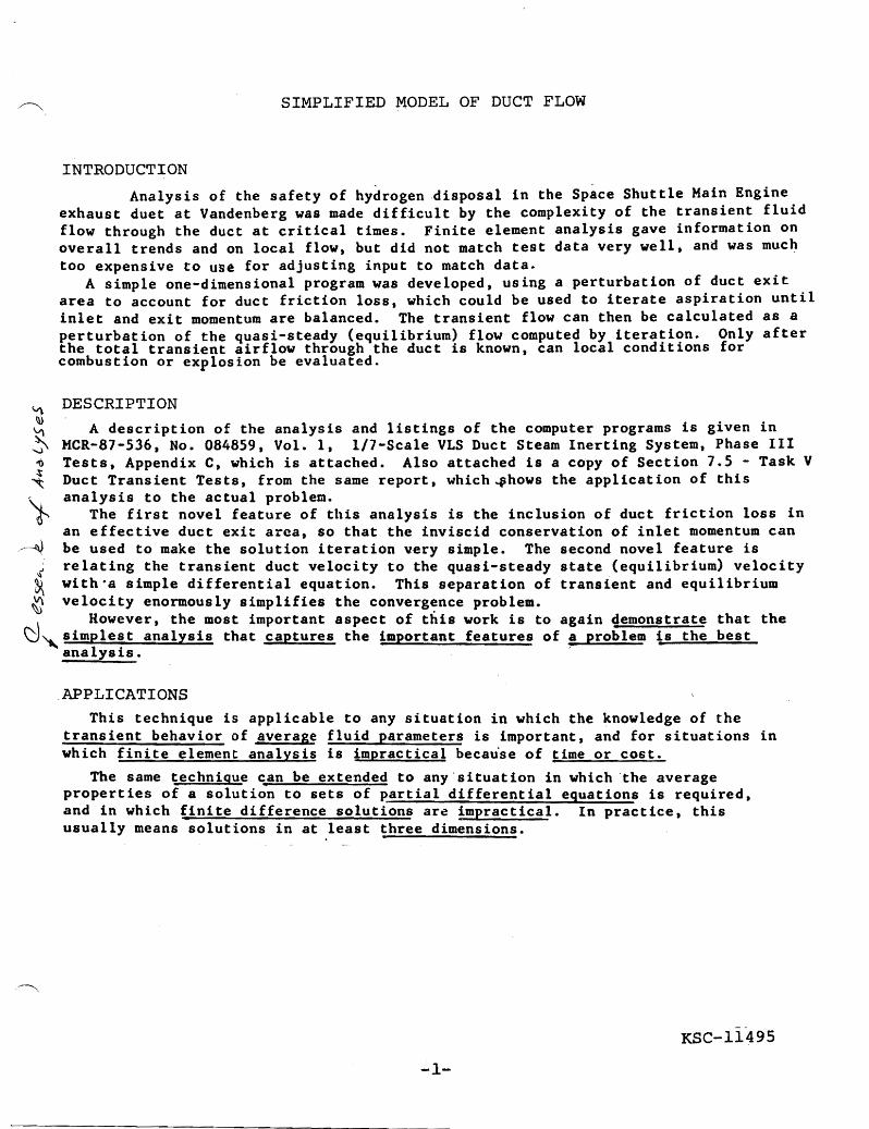
Analysis of the safety of hydrogen disposal in the Space Shuttle Main Engine exhaust duet at Vandenberg was made difficult by the complexity of the transient fluid flow through the duct at critical times Finite element analysis gave information on overall trends and on local flow but did not match test data very well and was much too expensive to u~e for adjusting input to match data
A simple one-dimensional program was developed using a perturbation of duct exit area to account for duct friction loss which could be used to iterate aspiration until inlet and exit momentum are balanced The transient flow can then be calculated as a perturbation of the quasi-steady (equilibrium) flow computed by iteration Only after the total transient airflow through the duct is known can local conditions for combustion or explosion be evaluated
- DESCRIPTION ~ ~ A description of the analysis and listings of the computer programs is given in ~ MCR-81-536 No 084859 Vol 1 11-Scale VLS Duct Steam Inerting System Phase III ~ Tests Appendix C which is attached Also attached is a copy of Section 15 - Task V
Duct Transient Tests from the same report which~hows the application of this ~ analysis to the actual problem ~ The first novel feature of this analysis is the inclusion of duct friction loss in
an effective duct exit arca so that the inviscid conservation of inlet momentum can ~ be used to make the solution iteration very simple The second novel feature is
~ relating the transient duct velocity to the quasi-steady state (equilibrium) velocity ~ witha simple differential equation This separation of transient and equilibrium ~ velocity enormously simplifies the converg~nce problem
~ However the most important aspect of this work is to again demonstrate that the J~simplest analysis that captures the important features of a problem is the best
analysis
APPLICATIONS This technique is applicable to any situation in which the knowledge of the
transient behavior of average fluid parameters is important and for situations in which finite element analysis is impractical beca~se of time or cost
The same technique can be extended to any situation in which the average properties of a solution to sets of partial differential equations is required and in which finite difference solutions ar~ impractical In practice this usually means solutions in at least three dimensions
KSC-11495
-1shy
MCR-87-536 No 084859 Vol Duct Stream Inerting System
1 17-Scale VLS Phase III Tests
APPENDIX C AIR ENTRAINMENT ANALYSIS
The a~entrainmen[ analysis requires establishment of a uasi-stead flowrate driven by the SSME and steam nozzle flows A momentum balance iterauon between ~t inlet and exit incorporating the engine and SIS flows and including aerodynamic shock loss of engine momentum provides the quasi-steady velocities through the operational envelop~_ O~ce the quasi-steady velocities are calculated ttansient velocities can be calculated_ An iteratIon to match transient velocity is used to determine the total duct airflow Acceptable results are provided by a conscious effon to keep the analysis as simple as possible emphasizing fIrst-order effects and one-dimensional flow_ Data from the Martin Marietta In-scale test series suppons the analysis
The equation for the ll-nnsient duct oelocit)middot can be simply expmiddotcssed in terms of the equilibrium duct -elocity in the follolinltg marlnero
If the duct velocity is defined to be the duct exil velocity Dnd it tho entrance lbss and the friction loss within the ducl arc expressed in terms of the duct exit dynamic pressure then
pll~ -- = exit dynamic pressure = exit loss2g
K( p2tmtrancelOss~ middotfrictionmiddotlOss
pv 2
(1+K)-2lt - middottota duct loss shyg lt
If the flow is in equilibrium the duct equilibrium velocity will be that velocity which results in a duct loss which results in a duct exit static pressure which is just equal to the ambient pressure The force available to accelerate or decelerate the fluid in the duct is just the difference between the equilibrium duct loss and the transient duct loss times the exit area or
i Lp bull m = - = mass Within the duct g
The rate-ot-change of the duct velocity is just the acceleration of the mass in the duct which in turn is just the ratio of the force to the mass
dV l+K)F-=a=-= (V2 _V2)dt m 2L It
KSC-i149~f
The duct pressure loss coefficien[~ K is determined using steam-air and helium-air test data Values of K are selected for the computation of velocities arising from a known system flow and the resulting entrained air flow
dv Vltt+~t) = V(t)+~tmiddot dt
where dv =(1 +K)ltY2 _y2)dt 2L f
and K =Duct Resistance Coefficient
L =Duct Length
V = Duct Quasi-Steady Velocity
V =Duct Velocity
These resulting velocities are compared against velocities computed from pitot pressure measurements for discrete locations in Plane D (Figures 7-13 -14 -15) Once K is known for the duct geometry it is independent of variatio 1 in gas mixture concentrations or scale factor and can be used for full size prediction
The quasi-steady duct flow and velocity obtained for each time step of the launch abon sequence (shutdown from RPL) shown in Figure C-1 are calculated using a momentum balance between the planes of the duct inlet and exiL Duct friction losses are incorporated when calculating exit momentum The total duct resistance loss is the sum of friction loss as ratioed to the duct exit dynamic head
pvi 2
and the dumping loss which is the duct exit dynamic head The total resistance is then
PV2
(I+K)--t
KSC-11495
-2Ashy
Scenario Three Engines at RPL I Engine-E 160
5 -4lc
c - 140 ct w ~ 0c 120
4l at i90 c
at~ 100 Cgtshyct
I 80 0 v J
CI) I lit 60(I
Shutdown Sequence-No1 No2 No3 shy
Eu 139 Max Detrimental shy o Unburned GH~ Flow Rate
E - ~~--~--------------------
E u
C(H11bined Detrimental-0 Unburned GH l -1 all shy
w ~ bullbullbullbullbull t2 --~- 4l
40c fQ ~gt middotmiddotB ( l--J-
Q c _ filii -_ 0 -
l 20 L Engine 1 Engine 2 Engine 3 0
Profile Profile Profile 0 o 1 2 3 4 6 7
Time I
Figure Cl FRF Shutdown Sequence from RPL (Case 2)
Now suppose the actual exit area is divided by the factor (l+K)1IZ so that the exit velocity is increased by the same factor The exit dynamic head will be increased by the factor (1 + K) so that the dumping loss with the adjusted ex i ~ area is exacdy equal to the acmal total duct resistance Thus a simple equality of inlet and exit momenmm can be used to iterate a solution to determine the aspirated air flowbull The Manin Marietta steamaair tests are used to evaluate the effective inlet momentum of the steam jets using the same adjusted exit area and thus accounting for duct friction loss in that evalu~tion
rilvOUT =(rilAIJI +1i1mw +mo)vour
Iilvour(l + K)1IZ =thvlN
where IilvlN = mvlla0+mvAIII
with vAlR =0
Once steam momentum is known the momenmm of propellants at full scale or helium at In-scale injected through the SSME nozzles can be added Evaluation of the nozzle flow momentum entering the duct is uncenain because of the variation in shock train losses as the -engine chamber pressure drops A simple conservative (approximately 6 greater loss than calculating multiple shocks) procedure is used (Ref 1) The ratio ofentrained air to engine propellant flow is 628 with a shock versus a ratio of 972 without the shock This is consistent with previous results of 60 obtained at MSFC The nozzle exit flow passes through a single normal shock to get[IhC approriatc ]IOSS in total pressure
(M-2) Pc =Pc bull
(tM2 _ T- 1+ I 1+1
KSc-11495
-3Ashy
where
and Pc =engine chamber pressure
p = ambient pressure
The flow is then expanded back to a static pressure equal to ambient to get an adjusted Mach number
M is a dimensionless velocity ratio (Ref 2)
fonned with the speed of sound at sonic conditions (M = 1) -so that for a given chamber temperature M is proportional to velocity Thus the ratio
is just the effect of shock loss on flow velocity where
Since momentum is mass flow times velocity the M ratio is also the effect of the shock loss on momentum
Momentummiddot = Momentum x M
Mmiddot
The components of an energy balance Figure C-2 are evaluated at static equilibrium at the exit establishing exit momentum The In-scale test results limit additional combustion of un burned hydrogen and air to 20 of the air available Iteration convergence of momentum between inlet
) and outlet is accomplished by adjusting entrained air flow
KSC-11495
-4Ashy
---Hl HlOVapor (to
H Air
------- HlOVapor
H20Liquid
183degF -
---- N 10 H2 0 Oropou
Figure C-2 Complex Duct Flow Chemistry which Quickly [nerts Unburned Hydrogen
Once the quasi-steady exit velocity for the abott condition is calculated the transient air flow and velocity can be determined The duct loss coefficient dctenmnes the aspiration decay rate for the entrained air The resulting transient velocity curve is used to determine total air flow through the dUCl A duct velocity balance is used to detennine conditions in the duct matching the transient velocity This calculated transient air flow is compared to the quasi-steady airflow at me time of interest to detennine the air flow ratio
Figure e-3 displays validation of the momentum balance-calculation of quasi-steady velocities
900
800
700
600 ~ 1 500 ~ 8 a I 400
11
300
200
00
0
(1bousandl) Helium Chamber Pressure psig
0 Turbine Data 0 RPLDuctvet 6 Design PI
Figure C-3 Correlation between Analysis and Dataor SngleEngne Helium and Steam Tests with K = 1
KSC-11495
-5Ashy
bull 00 2
using data from the steamone-engine helium flow tests aUlifferent helium chamber pressures The chamber pressure can be increased to at least 10000 psig without exceeding a duct exit Mach number of 44 Figure 7 -18 presents airflow versus chamber pressure for the same conditions
Figure C 4 illustrates perfonnance of a series of simulated full-scale helium-steam tests Maximum entrained air flow occurs at 3900 psig and 161481bms which is 83 of the 19383 Ibms obtained during RPL Engine momentum equal to RPL is reached at a helium pressure of 2474 psig which supplies an airflow of 80 of RPL These results indicate that helium is not capable of pumping the volume of air obtained in the combustion process The significance of this result is that helium flow simulation of RPL conditions is not appropriate for study of splash-back since the appropriate air entrainment cannot be achieved
20 o
18
16
14
12 ~ Qi
~i 10 u c ~t
8
6
shy
2
0 0
c RPt o Max AJI Flow
Figure C4 Full-Scale Helium-Stiam Air Flow Less Than RPL
The duct exit Mach number is calculated at RPL conditions in response to concern that the total flow is beginning to experience restriction due to velocity effects The molecular weight of all the gases is calculated for an exit temperature of 1830 F and yof 12 and 14 The resulting average Mach numbers are 0417 and 0386 respectively This reflects conventional duct design philosophy and confinns that the duct is not too resaictive
10 (Thousands)
Chamber Plessure psig 4 Equal Momenm
KSC-11495
The program listing middot-lOvlVEQFOR contains the analYsis for the momentum balance between ducl inlet and exit Nain engine shoclt loss and additional duct combustion are included
C MOMVEQFOR C C CALCULATES DUCT EXIT NOMENTUM A~D ITERATES TO 1-tATCH INLET C MOMENTUM GIVES FULL SCALE EQUILIBRIUM VELOCITY WRT TIiwlE C TOM LISEC 7-14-87 C
PROGRAN MOMVEQ
$ DEBUG S STORAGE2
OPEN(3FILE=MOi11DAT STATUS=OLD) OPEN(4FILE=INPDATSTATUS=OLD) OPEN (5FILE=MOf-1OUTSTATUS=NEi) OPEN(6FILE=MOM2DAT STATUS=OLD) OPEN(7FILE=MON3DATSTATUS=OLD)
READ(4)XKAIRFLOTISTOSAESMVINHWINXRHOLCPACPWHYKCPH + NDELTTAPA shy
WRITE(5620)
620 FORMAT(IX TIlIE EQVEL XX AIRFLO BRAr XMVIN XNV XN + UH2 XMACHl)
650 FORlotAT(F421XF612XF202XF712XF422XF90F90F40 + 2XF902XF40)
DO 700 I =1N
READ(3) T XME 1 VEl XME2 VE2XME3 VE3~IVE1
READ(6) XMVE2XMVE3EMV XMEUH2lUH22UH23UH2 READ(7) TEElTEE2TEE3PClPC2PC3
C LOSS MODIFIED EFFECTIVE DUCT FLOW AREA (FT2) AEFF = AE laquo1 + XK) 5)
C ENGINE 1 MOMENTUM REDUCED DUE TO SHOCK XNACHI = laquo2(HYK-lraquo) laquopelPA) laquoHYK-l )HYK)-l) )5
IF (XMACH1 LT 1) COTO 160
STARM1 =( laquo (HYK+1)2) (XMACHl)2)( 1+( (HYK-l )2)XMACHl2) )5
PCPRIM1 = PCl(STARM12)(HYK(HYK-ll) + laquo2HYK(HYI+1raquo(XlrIACH1)2-(HYI-1)(HYK+1) ) + (l(HYK-l)
~ x~IPRIMl = laquo2(HYK-l))CCPCPRIMlPA)laquoHYK-l)2)-l)U5
KSC-11495
-7Ashy
middot1
SRNPRlll = C laquoHYK+ 1 )2) (Xl-IPRIlIl) J 2( 1 + (( HYI-l )2) (XNPRI-Il) 2raquo + 5
XVIVEI = XMVEI SR~PIDrI15TARlrIl
GOTO 210
160 CONTINtE
C ENGINE 2 NONENTUM REDUCED DUE TO SHOCK 210 XMACH2 = ((2CHYI-1))((PC2PA)((HYK-1)HYK)-1))5
IFXMACH2 LT 1) COTO 170
STARM2 = Claquo(HYK+l)2)(XMACH2)2)( 1+( CHYK-l)2)~1-IACH22) )5
PCPRIM2 = PC2CSTARr-I22)CHYKCHYK-lraquo + C(2HYK(HYK+1) )CDolACH2) 2-~HYK-1 )uriK+1raquo (1fHA-1raquo
X1PRIM2 = C(2(HYK-1J)C(PCPRIN2PA)~laquoHYK-l)2)-1raquo5
SR~PRM2 = laquo(HYK+l)2)(X~PRI-12)2(1+laquoHYK-l)2)(XNPRn-I2)2raquo
+ 5
XMVE2 = XIVE2 SRMPRM2STARN2
GOTO 220
10 CONTINUE
C ENGINE 3 -middotMOMENTUM REDUCED DUE TO SHOCK 220 XMAcH3 = laquo2(HYK-lraquolaquoPC3PA)((HYK-l)HYK)-I))5
IF(XMACH3 LT 1) ltiOTO 180
STARM3 = laquo (CHYK+1)2)(XMACH3)2)( 1+( (HYK-l )2) DotACH3-2) )5
PCPRIM3 =PC3(STARM32)CHYK(HYK-lraquo + (2HYK(HYK+l raquofXNACH3)2-CHYK-l)(HYK+l) + (lCHYK-lraquo
XNPRIN3 = ((2(HYK-1raquo((PCPRI~3PA)((HYK-l J2)-1 n5
SR1PRM3 = C C UIYK+1)2)XMPRIM3)2( 1+( (HYl-1)2) (X~IPRI-13)2) J
+ 5
XNVE3 = XNVE3 bull SR-JPRN35TAR~t3
COTO 230
180 CONTINlE
C ENTRANCE NO~tENTtM (LB~I FTSEC2) 230 X~I~I~ = SNV]~ + X~VEI + XIE2 + XIVE3
KSC-11495
8Ashy
C NOZZLE STEAM (LBMSEC) ST~tIN = X HvIN
C ENGISE ~ASS FLOW COOLING HEAT REJECTION TO WATER (BTUSEC) HREI = XME1 CPW (TEE1 - TOS) HRE2 = XNE2 CPW (TEE2 - TOS) HRE3 = XME3 CPv (TEE3 - TOS)
C COOLING ENGINE EXHAUST TO IAKE STEA-l (LBMSEC) EECS = (HREI + HRE2 + HRE3) 970
DO 99 Kli = 1100
C HEATING INLET AIR BY CONDENSING STEAM TO lIAKE NEW H20 (LBNSEC) HRAIR = AIRFLO CPA (TOS - TA) HRAIR = HRAIR970
C 02 BURNED AS F(H2) (LBMSEC) 02 = 8 UH2
C BURSED AIRFLO RATIO IS IT 20 OR LESS OF AIRFLO BRAT = 0243l25AIRFLO IF( BRAT ~GTbullbull20 ) THEN 02 = 02AIRFLO 43125 BRAT = 2 ENDIF
C CREATED EXCESS N2 (LBMSEC) XSN2 = 33125 02
C NEWLY BURNED UH2 BH2 =02 8
C NEW STEAM (LBMSEC) XNS = 02 + BH2
C REMAINING UNBURNED H2 RUH2 = UH2 - BH2
C CORRECTION TO LOGIC FOR NO H2 FLOW IF( UH2 EQ 00) UH2 = 0001
C COOLING REMAINING UNBURNED H2 TO MAKE STEAN HRU21 = RUH2UH2 UH2l CPH (TEEI - TOS) HRU22 = RUH2UH2 UH22 CPH (TEE2 - TOS) HRU23 = RUH2UH2 UH23 CPH (TEE3 - TOS)
C COOLING SU~INATION CRUH2 = (HRU21 + HRU22 + HRU23) 970
KSC-11495
middot-9Ashy
C CONBtSTIOS AND COOLING OF AIR + UH2 (LBMSEC) C LOWER HEATING VALUE OF H2 = 51571 BTULBN
HRCC = 51571 XNS4032 1970
C SEW STEAM GENERATED (LBMSEC) XNNS = EECS + HRCC + CRUH2
C EXIT ~ASS FLOlv OF STEAM CONPONENTS (LBNSEC) STMOUT = STfvllN + XNNS + XNS - HRAIR
C iATER DROPLETS AT EXIT (LBvlSEC) HWOUT = 9 HwiN - STt-IIN - XNNS + HRAIR
C UNBURNED AIR (LBMSEC) AIROUT = AIRFLO - 02 - XSN2
C lrlOLES OF MIXTURE ETAH20 = STMOUT1802 ETAN2 = XSN22S02 ETAAIR = AIROUT 2S97 ETAH2 = RUH2 2016
ETAT = ETAH20 + ETAN2 + ETAAIR + ETAH2
C MOLE FRACTION XH20 = ETAH20ETAT XN2 = ETAN2ETAT XAIR =ETAAIRETAT XH2 =ETAH2ETAT
C flIXTURE MOLECULAR WEIGHT XM = (STMOUT + XN2 + AIROUT + RUH2) ETAT
C AVERAGE GAS MIXTURE DENSITY (LBMFT3) RHOM = PA 144 XM( 1545 TOS)
C TOTAL DENSITY (LBMFT3) RHOT = RHOM (STMOUT + HWOUT + XSN2 + AIROUT + RtH2)
+(STMOUT + XSN2 + AIROUT + RUH2)
VEFF = (STNOUT + HlvOUT + XSN2 + AIROUT + RUH2)(RHOT AEFF)
VEQ = VEFF laquo1+XK) 5)
XMV = (ST~JOUT + HWOUT + XSN2 + AIROUT + RUH2) VEFF
DELMV = XMVIN - x1V
IF(ABSDELMV) LE (OOOOOOlXMVINraquo GO TO 600
AIRFLO = (XNVISXMV)AIRFLO
99 IF(AIRFLO LE 0) GOTO sao
KSC-11495
~lO1-
WRITE((A)) CO~VERGENCE DID NOT OCCUR IN 100 PASSES
600 CONTINUE
WRITE (5650) T VEQtXKtAIRFLO BRAT XMVINt~MV XvI UH2XMACH1
700 CONTINUE GOTO 900
800 CONTINUE
WRITE(5670)
670 FORMAT(lXBACKFLOW INMINENT - COVER THE DUCT)
900 CONTINUE
STOP
END
- shyKSC-ll4middot9S
-llA-shy
The program listing DlCTAFOR uses the quasi-steady duct middotelocity and duct loss characteristics to generate the transient duct velocity
C DUCTAFOR C C COMPARES TRANSIENT AND EQUILIBRIUM VELOCITIES DURING -~ SS~IE C PART SCALE OR FULL SCALE STARTUP-SHUTDOlvN EVET C TOM LISEC 1-27-87 C
PROGRAN DUCTA
S STORAGE2
OPEN (3FILE= DUCT DAT STATUSOLD) OPEN (4 FILE=DUCTOUTSTATUS=NEW)
PI = 3141593 A = 0 F =0
C C SCREEN INTERACTIVE PROMPTS ---------------------------------------- shy
WRITE((A)) DUCT DIAMETERFT READ() DEFF WRITE((A)) DUCT LENGTHFT READ() Xi WRITE((A)) DUCT FRICTION DISSIPATION CONSTANT FLD-DLESS READ() XK WRITE((A)) KINEMATIC VISCOSITYFT A 2SEC READ( ) XNU WRITE((A)) INITIAL TIMESEC READ() TI vRITE((A)) FINAL TIME SEC (ENTER OIF VEL FREQ DEP) READ() TF WRITE((A)) TINE STEP SEC (ENTER 0 IF VEL FREQ DEP) READ() DELT WRITE((A)) INLET VELOCITY FTSEC READ() VIN WRITE((A)) VELOCITY TRANSIENT AMPLITUDE FTSEC READ() A WRITE((A)) FREQUENCY HZ READ() F
C
C PRINT FORMAT ------------------------------------------------------ shyWRITE(4570) DEFF
570 FORMAT(DUCT DIAMETER FIO2 FT) WRITE(4575) XL
5i5 FORMATeDUCT LENGTHFIO2 FT) WRITE(4578) XNU
578 FORMAT(KINENATIC VISCOSITY F108 FT2SEC) WRITE(4579) A
579 FORilATCVELOCITY TRANSIENT AfvlPLITUDE = FIO2 FTSEC) WRITE(4580) F
580 FORNATCOSCILLATION FREQL1ENCY =FIO2 HZ) KSC-11495
WRITE(4590) 590 FORMAT(7XTIME 7X K 8XREYNOLDS 6XVEL 4XEQVEL
+5XVVEQ) WRITE(4592)
592 FORNAT(8XSEC 21X~O 4XFTSEC 3X FTSEC ) C
C irIAIN COMPUTATIONS OMEG =2PIF T =TI
-------------------------------------------------shy
V = VIN
C SELECTS DELT AND RUN DtRATION BASED ON FREQ IF( F GTO) THEN TF = SF DELT = 1F ENDIF
620 RE = VDEFFXNU C SELECTS FREQUENCY DEPENDENT TEST VELOCITY RELATIONSHIPS
IF(F EQ 0) GO TO 615 CALL SCA~VEQ(VINAOMEGTVEQ)
615 CONTINUE
READ(3) N DO 630 I=IN
617 CONTINUE
READ(3) TVEQ
DVDT = (I+XK)C2XL)(VEQ2-VABS(Vraquo
IF(VEQ LE 00) THEN VEQ = VEQ + 0001 ENDIF
VRAT = VVEQ
WRITE(4600) TXKREVVEQVRAT 600 FORNAT(2X2(F102)F1523(F102))
v = V +DELTDVDT 630 CONTINUE
END c C FREQUENCY DEPENDENT EQUILBRIUN VELOCITY PROFILE C
SUBROUTINE SCALVEQ(VINAOMEGTVEQ) VEQ = VIN + ASIN(OMEGT) RETURN END
C KSC-1149Sshy
-13Ashy
C FREQUENCY INDEPENDENT EQUILIBRIUM VELOCITY PROFILE C
SUBROUTINE FULLVEQ(TVEQ) IF (T LE 015) THEiJ
VEQ = 945 (T15) ELSEIF (T GT 015 AND T LE 025) THE
VEQ = 945 + 177 laquoT-15)10) ELSEIF(T GT 025 AND T LE 2) THEN
VEQ = 1122 + 88 laquoT-25)175) ELSEIF (T GT 2bullbullAND T Lh 215) THEN
VEQ = 1210 - 1210 (T - 2)15 ELSEr (T GT 215) THEN
VEQ = O ENDIF
RETURN END
KSC-11495
-14Ashy
~ The program listing TVBALFOR uses the transient duct middotelocit~middot for a elocity balance to determine total sirno
C TVBALFOR C C CALCULATES DUCT EXIT VELOCITY AND ITERATES TO NATCH TRAgtJSIEKT C EXIT VELOCITY GIVES FULL SCALE TRA~SIENT AIRFLOi ~RT TINE C TOM LISEC 8-20-87 C
PROGRA~ TVBAL
$ DEBUG $ SlORAGE2
OPEN( 3FILEMOM1DATSTATUSOLD) OPEN( 4FILEINPDATSTATUSOLD) OPEN (5 FILETVBALOUTSTATUSNEW) OPEN(6FILEMOM2DATSTATUSOLD) OPEN(7FILEMON3DATSTATUSOLD) READ(4) XKAIRFLOTISTOSAESMVINHWINXRHOLCPACpwHYKCPH
+ NDELTTAPA
WRITE(5620) 620 FORltAT ( IXTI~1E EQVEL XX AIRFLO BRAT XMVI~ ~IV XI
+ UH2 XMACHl) 650 FORl1AT(F42lXF6l2X-F202XF7l~2XF422XF90F9OF40
+ 2XF902XF40)
DO 700 I = lN
READ(3) T XMEIVElXME2VE2DrIE3 VE3X1YIVEl READ(6) XMVE2XMVE3EMVXMEUH21UH22UH23UH2 READ (7 ) TEElTEE2TEE3PCIPC2PC3TVEL
C LOSS MODIFIED EFFECTIVE DUCT FLOW AREA (FT2) AEFF AE t( 1 + XK) 5)
C ENGINE 1 MOMENTUM REDUCED DUE TO SHOCK XMACHl laquo(2(HYK-I) )( (PClPA)( (HYK-l )HYK)-l) )5
IF(XMACHI LT 1) GOTO 160
STARMl = laquolaquoHYK+I)2)(X~ACHl)2)(1+((HYK-l)2)XMACHI2))5 PCPRIMI =PC1(STARMl2)(HYK(HYK-lraquo
+ ( (2HYK(HYI+1) )(L~CHl) 2-(HYK-l ) (HYK+1) ) (l(HYK-l))
XMPRIwll = laquo2(HYK-lraquo( (PCPRIMlPA)laquoHYK-1 )2)-1) )5 SRMPRMI =laquo (HYK+1)2)(XMPRIMI ) 2 (1 +( (HYK-l )2) (XMPRIM1 )2raquo)
+ 5
XtIVEl XlIVEl SRNPRMISTARNI
GOTO 210 KSC-l149S
-15Ashy
160 CONTINUE
C ENGIJE 2 MONENTUM REDUCED DUE TO SHOCK 210 XMACH2 = laquo2(HYK-l))((PC2PA)CCHYK-I)HYK)-l))5
IFCX~IACH2 LT 1) GOTO 170
STARM2 = (C laquoHYK+l )2) (XMACH2) 2)( 1+( (HYK-1 )2)iXNACH22) l5 PCPRIM2 = PC2t(STARM22)CHYKCHYK-1raquo
+ laquo2HYK(HYK+l raquo(XNACH2)2-CHYK-1 )(HYK+l) )i( 1(HYI-1)) XMPRIM2 = (C2(HYK-1) )( (PCPRIN2PA)C (HYK-1 )2)-1 raquo5 SRvIPRl-12 = ( (HYIi+l )2) (XMPRli12 )2( 1+( (HYK-l )2) (XNPRIN2) 2))
+ 5
XlIVE2 = XNVE2 SRMPRN2STARM2
GOTO 220
1iO CONTINUE
C ENGINE 3 NOfwlENTUM REDUCED DUE TO SHOCK 220 XMACH3 = laquo2(HYK-lraquolaquoPC3PA)((HYI-1)HYK)-1raquo5
IF(XMACH3 LT I GOTO 180
STARM3 = laquolaquoBYK+ll2)(XMACB3)2)( l+laquoHYK-l)2)XiIACH32) )5 PCPRIM3 = PC3(STARM32)(HYK(HYK-ff)
+ laquo2HYK(HYK+lraquo(XMACH3)2-(HYI-1)(HYK+lraquo + (l(HYK-lraquo
XMPRIM3 = laquo 2(HYK-lraquo((PCPRIM3PA) laquoHYK-1)2 )-1raquo5 SRMPRM3 = laquo (HYK+1)2)(XMPRIM3)2(1+( (HYK-l)2)(XMPRIM3)2)
+ 5
X~VE3 = XMVE3 SRMPRM3STARM3
GOTO 230
180 CONTINUE
C ENTRk~CE MOMENTUM (LBM FTSEC2) 230 XMVIN = SMVIN + D-IVE 1 + X1VE2 + XMVE3
C NOZZLE STEAM (LBMSEC) STMIN = X HWIN
C ENGINE MASS FLOW COOLING HEAT REJECTION TO vATER (BTtTSEC) HREl = XMEl cp (TEEl - TOS) HRE2 = XNE2 CP1 (TEE2 - TOS) HRE3 = XME3 CPW (TEE3 - TOS)
C COOLING ENGINE EXliAtST TO MAKE STEA~ (LBNSEC EECS = (HREI + HRE2 + HRE3) 90
KSC-11495DO 99 II = 150
-~
16Ashy
C HEATING INLET AIR BY CONDENSING STEA-l TO NAIE NEW H20 (LBMSEC) HRAIR = AIRFLO CPA i (TOS - TA) HRAIR = HRAIR970
C 02 BURNED AS F(H2) (LBNSEC) 02 = 8 UH2
C BURNED AIRFLO RATIO IS IT 20 OR LESS OF AIRFLO BRAT = 0243125AIRFLO IF( BRAT GT bullbull20 ) THEN
02 = 02AIRFLO 43125 BRAT = 2 ENDIF
C CREATED EXCESS N2 (LBMSEC) XSN2 = 33125 02
C NEWLY BURNEDUH2 BH2 = 02 8
C NEli STEAM (LBMSEC) XNS = 02 + BH2
C REMAINING UNBURNED H2 RUH2 = UH2 - BH2
C CORRECTION TO LOGIC FOR NO H2 FLOW I
IF(UH2 EQ 00) UH2 = 0001
C COOLING REMAINING UNBURNED H2 TO MAlE STEraquoI HRU21 =RUH2UH2 UH21 CPH (ItEE1 - TOS HRU22 = RUH2UH2 UH22 CPH (TEE2 - TOS)
bull HRU23 =RUH2UH2 UH23 CPH (~EE3 - TOS)
C COOLING SUMflATION I CRUH2 = HRU21 + HRU22 + HRU23) ~70
C COMBUSTION AND COOLING OF AIR + UH2 ~LBMSEC) C LOWER HEATING VALUE OF H2 =51571 BTlfLBM
HRCC = 515i1 XNS4032 1970
C NEli STEAM GENERATED (LBMSEC) XNNS = EEes + HRCC + CRUH2
C EXIT MASS FLOW OF STEAM COMPONENTS CLBMSEC) STMOUT =STMIN + XNNS + XNS - HRAIR
C WATER DROPLETS AT EXIT (LBMSEC) HWOUT = 9 HWIN - STMIN - X~NS + iHRAIR
C UNBURNED AIR (LBMSEC) AIROUT = AIRFLO - 02 - XSN2
-17Ashy
C MOLES OF MIXTURE ETAH20 = STNOUT11802 ETAN2 = XSN22802 ETAAIR = AIROUT2897 ETAH2 = RUH2 1 2016 ETAT = ETAH20 + ETAN2 + ETAAIR + ETAH2
C MOLE FRACTION XH20 = ETAH20ETAT XN2 = ETAN2ETA T XAIR = ETAAJRETAT XH2 = ETAH2ETAT
C MIXTURE MOLECULAR WEIGHT XM = (STMOUT + XN2 + AIROUT + RUH2) ETAT
C AVERAGE GAS MIXTURE DENSITY (LBMFT3) RHOM = PA 144 XltU(1545 TOS)
C TOTAL DENSITY (LBMFT3) RHOT = RHOM (STMOUT + HWOUT + XSN2 + AIROUT + RUH2i
+(STMOUT + XSN2 + AIROUT + RUH2)
VEFF = (STMOUT + HWOUT + XSN2 + AIROUT + RUH2)(RHOT AEFF) VEQ = VEFF laquo1+XK) 5) DELV = TVEL - VEQ IF(ABS(DELV) LE (OOOlTVELraquo GO TO 60~
AIRFLO = (TVELvEQ)AIRFLO 99 IF(AIRFLO LE 0) GOTO 800
WRITE((A)) CONVERGENCE DID NOT OCCUR IN 50 PASSES 600 CONTINUE
WRITE (5650) TVEQXKAIRFLOBRA T XMVINXMV XM UH2XMACHI
700 CONTINUE GOTO 900
800 CONTINUE
lvRITE(5670) 670 FORMAT(lXBACKFLOlv IM~tINENT - COVER THE DtCT)
900 CONTINUE
STOP
END
KSC-11495
-18Ashy
REFERENCES
1) Shapiro A H uThe Dynamics and Thennodynamics of Compressible Fluid Flow Vol 1 pp 135middot137~ The Ronald Press Company New York 1953
I e 2) Shapiro A H The Dynamics and Thennodynamics of Compressible Fluid Flow Vol I P 81 The Ronald Press Company New York 1953
KSC-ll4~5
-19A-middot ~
75 TASK V-DUCT TRANSIENT TESTS
751 Approach
The purpose of these teSlS was (0 determine whether duct transient flow had a significant effect on the lesl condilions that should be simulated for SIS demOnSlr1uion and 10 proshyvide sufficient data to calculate those condilions A series 0
KSC-11495
-20A-
leSIS was planned using helium at selected steady flow rates with the helium then to be shut off as rapidly as possible This I71S cxpected to give the opponunity to measure both the steady now as a function of helium flQw rale and 10 give a series of transient measurements with (he steam system operating continuously It v-as realized that such sudden shutoffs would excite organ pipe response oscillations in the duct but calculations indicated that the lowest organ pipe frequency would be about 11 Hz which would not interfere with the measurements
Unfonunately the first tests showed that the duct organ pipe frequency was much lower than expected about 1 Hz Furshyther the magnitude of the oscillations was so large that only a qualitllive evaluation of the transient flow could be obshytained The wave speed in a duct and consequently the organ pipe frequency is a function of the compressibility of the fluid and extendabilil) of the duct walls Examination of the duct revealed flat regions where a tow force of a few pounds could move the duct wall an inch or so Thus an unexpected result of the duct construction technique invalishydated the intended procedure for measurement of transient flow
This made necessary the use of a different measurement technique A hot-wire anemometer bad been installed at the cnttance of the duct in the hope that it could be correlated 10
the lOW air flow Results showed that it was completely insensitive to the pumping of the helium jet The measure ment could be correlated with the air flow pumped by the steam jers but could not be correlated wilh lOW air flow A turbine anemometer placed in the duct showed a good meashysure of steady velocities but its time conslant made imposshysibl~ the measurement of ttansient ~clocitics A new test was then added 10 the series A hot-wire anemometer was placed in the duct near the turbine anemometer Obviously steam flow could not be used so the test us--d helium only The bot wire was calibrated using the no-flow condition and the sampCady-state reading of the turbine anemometer The hot wire shows some fluctuation because of the organ pipe efshyfect but the effect is minor compared to the effcct on the measured duct impact pressures (which arc referenced 10
external ambient pressure)
752 Duct Loss Coefficient
Figure 7-12 presentS the measured duct velocity transient using a hot-wire anemomelCr at Zone O Superimposed are the equilibrium (quasi-steady-state) velocil) caused by the helium jet and a calculation of the transient velocity using a duct loss coefficient of 10 The duct loss coefficient is defined to be the friction loss in the duct divided by the duct dynamic pressure NOle that it does not include the duct exit dumping loss The agreement between measured and calcushylated duct velocity is c-tceUent for both buildup and decay of
150 Ifnf1
bull bull bull bull E b n VtluCII
~ - Mr utd V~loIV120 jiJrmiddot _- - - - T nl V luC I to 1(
1
- 90 II I bull
~ i I
~ ~ 60
~
~30
r O~--------------~----------------
o 2
Figure 7-12 Duct Transient Flow (Helium Only Run JJ)
flow through the duct Thus at least for the flow wilhout steam the existence of transient flow is clearly demonshystrated and a duct loss coefficient of 10 characterizes the flow through the duct The duct loss coefficient should be a characteristic of the duct geometry and YOuld not be exshypected to change with the fluid in the duct To confirm this invariance pressure data from the transient run with the
least organ pipe effect Test 34 was compared with transhysient calCulations Figures 7middot13 through 7-15 compare veshylocities computed from measured impact pressure at several Zone 0 locations with transient velocities computed for duct loss coefficients of 00 10 and 30 Although the results arc distorted by the organ pipe effect a value of 10 is consistent with the measured pressures
753 Transient Effect
The evaluation of the transient effect for shutdown from RPL is made diflicult by the fact that a good deal of uncershytainEy exists concerning the eqUilibrium flow conditions at RPL and even more uncertainEy existS concerning the quasi-steady tlow during the shutdown A program has been written that evaluates duct inlet momentum from the SSMEs including shock losses and from the steam jets Empirical equations from lCStS calculate the hydrogen comshybustion in the dUCI inlet A heat balance determines the water evaporated in the duct A duct pressure loss is apshyplied and the dUcl air aspiration is iterated until the exit and inlet momentum are balanced This makes possible a conshysistent calculation of quasi-steady ducl velocity during shutshydown from RPL Then the transient duct velocity and the additional aspirated air due to the transient flow can be calculated Figure 7middot16 shows the results of these calculashytions during shutdown from RPL Appendix C conrains program listings and a discussion of the theory used
KSC-11495
-21Ashy
200
Mesured Velocity - - Cllculaed Trllnenc Velocity bullbullbullbullbull Equilibrium Velocity
150
Vlocity his
100
50
bullbullbullbullbullbullbullbullbullbull
O~-----------------r-----------------T----------------~----~--~------~------middot05 o 05 10 15
Tim bullbull s
Figure 7middot13 Duct Transient Flow-Location 20 (Helium and Stem Run 34) 200
Mred VDcity Calculated Trnsient VelDcity
bullbullbullbullbull Equilibrium Velocity
150
~oo
1 gt
50
o middot05 o 05 10 15
Figure 7middot1-1 DUCI Trallstllt Flow-Locatioll 21 (Helillm i111d Steam RlIlI 34) KSC-11495
-22Ashy
200
Legend
Musured VelocilY Calculated Transienl Velocity
bullbullbullbull - Equilibrium Velocity
Velocity hI
150
100
50
o ~----------------~-----------------r-----------------r------------------05 o 05 10 15
Time
Figure 1middot15 Duct Transient Flow-Location 23 (Helium and Steam Run 34) 22
20
18 Lnd
16 QubullbullimiddotStedy
Transient
14
8
amp
4
2
o~--------~------~------~--------~--------~--------~--------~---------o 2 4 6
Times
Figllre 7-16 Predicted Duct -lir Flow Jllri Sblltdotl1 [rom RPL -23Ashy
All of these calculations use a dUCI loss coefficient of 10 helium pressure on duct flow Figure 7-18 presenls calculashyThe 3spiraled air flow 3( RPL is calculated (0 be over lions tor 3ir flow as a funclion of helium pressure The air 19000 Ibis about six limes the mass How of the three low increases with helium pressure up to a value of 10000 SSMEs NOlO that the aspiraled air now does not have the psi Bccause general duct bacldlow could not occur unlil smooth character associated with lhe decrease ofduct velocshy even higher helium pressures were reached this strongly ity The air flow also refleclS me changing composition of suggests that the observed backflow must be a consequence me flow For instance from time = 0 to about 08 seconds of local flow conditions Specifically the proximity of the air flow increases to compensate for the sudden drop in No 1 engine to the west wall makes it probable that a engine flow locally separated flow is the cause of the splashback Apshy
pendix C Figure C-2 presents data correlation with analyshyThe paramecer of interest to me design of the steam inening ses which substantiate the calculation of airflow as a funcshysystem is the ratio of the transient air flow to the quasishy tion of helium pressure Slcady-state airflow Figure 7-17 presents this ratio for the entire shutdown process The design point for the SIS is the time at which the last engine reaches an oxidizer-to-fuel ratio of one the condilion for which combustion inside the engine ceases This design poim is reached at 40 seconds and the air flow ratio at this time is 2SS
754 Observed Splashback
During the highest helium pressure test (Run 35) a signifi cant water backtlow was observed Concern about the cause of this backtlow prompted an analysis of the effect of nozzle
35
3
Ibullbull
25
~ bullI 0 2
Cbull
bullc
i a
05
O~--------r-------~--------T-------~--------~-------r--------r--------r o 2 6 8
Time I
Figure 7-17 Predicted Air FloUJ Ratio durig ShltdowIl from RPL
KSC~~~49~
--24A-
260 17middotScl Entrained Air
240 SingI Engine Helium and Stam K-l
220
200
180
110
140
100
10
20
O~----~__----~----~------~----~------~----~------~----~------r-----~----~ o
IThCKIndU
Helium elMm Preuure paig
Figure 7-18 Predicted Effect ofHelium Pressure on Duct Air Entrtlinment
KSC-11495
-25Ashy
Technical Support Package
For
SIMPLIFIED MODEL OF DUCT FLOW
KSC-11495
NASA Tech Briefs
The information in this Technical Support Package comprises the
documentation referenced in KSC-11495 of NASA Tech Briefs It is
provided under the Technology utilization Program of the National
Aeronautics and Space Administration to make available the results
of aerospace-related developments considered to have wider
technological scientific or commercial applications
Additional information regarding research and technology in this
general area may be found in Scientific and Technical Aerospace
Reports (STAR) which is a comprehensive abstracting and indexing
journal covering worldwide report literature on the science and
technology of space and aeronautics STAR is available to the
public on subscription from the Superintendent of Documents US
Government Printing Office Washington DC 20402
NOTICE This document was prepared under the sponsorship of the National Aeronautics and Space Administration Neither the United States Government nor any person acting on behalf of the united States Government assumes any liability resulting from the use of the information contained in this document or warrants that such use will be free from privately owned rights
---------------------------------------------------
SIMPLIFIED MODEL OF DUCT FLOW
INTRODUCTION
Analysis of the safety of hydrogen disposal in the Space Shuttle Main Engine exhaust duet at Vandenberg was made difficult by the complexity of the transient fluid flow through the duct at critical times Finite element analysis gave information on overall trends and on local flow but did not match test data very well and was much too expensive to u~e for adjusting input to match data
A simple one-dimensional program was developed using a perturbation of duct exit area to account for duct friction loss which could be used to iterate aspiration until inlet and exit momentum are balanced The transient flow can then be calculated as a perturbation of the quasi-steady (equilibrium) flow computed by iteration Only after the total transient airflow through the duct is known can local conditions for combustion or explosion be evaluated
- DESCRIPTION ~ ~ A description of the analysis and listings of the computer programs is given in ~ MCR-81-536 No 084859 Vol 1 11-Scale VLS Duct Steam Inerting System Phase III ~ Tests Appendix C which is attached Also attached is a copy of Section 15 - Task V
Duct Transient Tests from the same report which~hows the application of this ~ analysis to the actual problem ~ The first novel feature of this analysis is the inclusion of duct friction loss in
an effective duct exit arca so that the inviscid conservation of inlet momentum can ~ be used to make the solution iteration very simple The second novel feature is
~ relating the transient duct velocity to the quasi-steady state (equilibrium) velocity ~ witha simple differential equation This separation of transient and equilibrium ~ velocity enormously simplifies the converg~nce problem
~ However the most important aspect of this work is to again demonstrate that the J~simplest analysis that captures the important features of a problem is the best
analysis
APPLICATIONS This technique is applicable to any situation in which the knowledge of the
transient behavior of average fluid parameters is important and for situations in which finite element analysis is impractical beca~se of time or cost
The same technique can be extended to any situation in which the average properties of a solution to sets of partial differential equations is required and in which finite difference solutions ar~ impractical In practice this usually means solutions in at least three dimensions
KSC-11495
-1shy
MCR-87-536 No 084859 Vol Duct Stream Inerting System
1 17-Scale VLS Phase III Tests
APPENDIX C AIR ENTRAINMENT ANALYSIS
The a~entrainmen[ analysis requires establishment of a uasi-stead flowrate driven by the SSME and steam nozzle flows A momentum balance iterauon between ~t inlet and exit incorporating the engine and SIS flows and including aerodynamic shock loss of engine momentum provides the quasi-steady velocities through the operational envelop~_ O~ce the quasi-steady velocities are calculated ttansient velocities can be calculated_ An iteratIon to match transient velocity is used to determine the total duct airflow Acceptable results are provided by a conscious effon to keep the analysis as simple as possible emphasizing fIrst-order effects and one-dimensional flow_ Data from the Martin Marietta In-scale test series suppons the analysis
The equation for the ll-nnsient duct oelocit)middot can be simply expmiddotcssed in terms of the equilibrium duct -elocity in the follolinltg marlnero
If the duct velocity is defined to be the duct exil velocity Dnd it tho entrance lbss and the friction loss within the ducl arc expressed in terms of the duct exit dynamic pressure then
pll~ -- = exit dynamic pressure = exit loss2g
K( p2tmtrancelOss~ middotfrictionmiddotlOss
pv 2
(1+K)-2lt - middottota duct loss shyg lt
If the flow is in equilibrium the duct equilibrium velocity will be that velocity which results in a duct loss which results in a duct exit static pressure which is just equal to the ambient pressure The force available to accelerate or decelerate the fluid in the duct is just the difference between the equilibrium duct loss and the transient duct loss times the exit area or
i Lp bull m = - = mass Within the duct g
The rate-ot-change of the duct velocity is just the acceleration of the mass in the duct which in turn is just the ratio of the force to the mass
dV l+K)F-=a=-= (V2 _V2)dt m 2L It
KSC-i149~f
The duct pressure loss coefficien[~ K is determined using steam-air and helium-air test data Values of K are selected for the computation of velocities arising from a known system flow and the resulting entrained air flow
dv Vltt+~t) = V(t)+~tmiddot dt
where dv =(1 +K)ltY2 _y2)dt 2L f
and K =Duct Resistance Coefficient
L =Duct Length
V = Duct Quasi-Steady Velocity
V =Duct Velocity
These resulting velocities are compared against velocities computed from pitot pressure measurements for discrete locations in Plane D (Figures 7-13 -14 -15) Once K is known for the duct geometry it is independent of variatio 1 in gas mixture concentrations or scale factor and can be used for full size prediction
The quasi-steady duct flow and velocity obtained for each time step of the launch abon sequence (shutdown from RPL) shown in Figure C-1 are calculated using a momentum balance between the planes of the duct inlet and exiL Duct friction losses are incorporated when calculating exit momentum The total duct resistance loss is the sum of friction loss as ratioed to the duct exit dynamic head
pvi 2
and the dumping loss which is the duct exit dynamic head The total resistance is then
PV2
(I+K)--t
KSC-11495
-2Ashy
Scenario Three Engines at RPL I Engine-E 160
5 -4lc
c - 140 ct w ~ 0c 120
4l at i90 c
at~ 100 Cgtshyct
I 80 0 v J
CI) I lit 60(I
Shutdown Sequence-No1 No2 No3 shy
Eu 139 Max Detrimental shy o Unburned GH~ Flow Rate
E - ~~--~--------------------
E u
C(H11bined Detrimental-0 Unburned GH l -1 all shy
w ~ bullbullbullbullbull t2 --~- 4l
40c fQ ~gt middotmiddotB ( l--J-
Q c _ filii -_ 0 -
l 20 L Engine 1 Engine 2 Engine 3 0
Profile Profile Profile 0 o 1 2 3 4 6 7
Time I
Figure Cl FRF Shutdown Sequence from RPL (Case 2)
Now suppose the actual exit area is divided by the factor (l+K)1IZ so that the exit velocity is increased by the same factor The exit dynamic head will be increased by the factor (1 + K) so that the dumping loss with the adjusted ex i ~ area is exacdy equal to the acmal total duct resistance Thus a simple equality of inlet and exit momenmm can be used to iterate a solution to determine the aspirated air flowbull The Manin Marietta steamaair tests are used to evaluate the effective inlet momentum of the steam jets using the same adjusted exit area and thus accounting for duct friction loss in that evalu~tion
rilvOUT =(rilAIJI +1i1mw +mo)vour
Iilvour(l + K)1IZ =thvlN
where IilvlN = mvlla0+mvAIII
with vAlR =0
Once steam momentum is known the momenmm of propellants at full scale or helium at In-scale injected through the SSME nozzles can be added Evaluation of the nozzle flow momentum entering the duct is uncenain because of the variation in shock train losses as the -engine chamber pressure drops A simple conservative (approximately 6 greater loss than calculating multiple shocks) procedure is used (Ref 1) The ratio ofentrained air to engine propellant flow is 628 with a shock versus a ratio of 972 without the shock This is consistent with previous results of 60 obtained at MSFC The nozzle exit flow passes through a single normal shock to get[IhC approriatc ]IOSS in total pressure
(M-2) Pc =Pc bull
(tM2 _ T- 1+ I 1+1
KSc-11495
-3Ashy
where
and Pc =engine chamber pressure
p = ambient pressure
The flow is then expanded back to a static pressure equal to ambient to get an adjusted Mach number
M is a dimensionless velocity ratio (Ref 2)
fonned with the speed of sound at sonic conditions (M = 1) -so that for a given chamber temperature M is proportional to velocity Thus the ratio
is just the effect of shock loss on flow velocity where
Since momentum is mass flow times velocity the M ratio is also the effect of the shock loss on momentum
Momentummiddot = Momentum x M
Mmiddot
The components of an energy balance Figure C-2 are evaluated at static equilibrium at the exit establishing exit momentum The In-scale test results limit additional combustion of un burned hydrogen and air to 20 of the air available Iteration convergence of momentum between inlet
) and outlet is accomplished by adjusting entrained air flow
KSC-11495
-4Ashy
---Hl HlOVapor (to
H Air
------- HlOVapor
H20Liquid
183degF -
---- N 10 H2 0 Oropou
Figure C-2 Complex Duct Flow Chemistry which Quickly [nerts Unburned Hydrogen
Once the quasi-steady exit velocity for the abott condition is calculated the transient air flow and velocity can be determined The duct loss coefficient dctenmnes the aspiration decay rate for the entrained air The resulting transient velocity curve is used to determine total air flow through the dUCl A duct velocity balance is used to detennine conditions in the duct matching the transient velocity This calculated transient air flow is compared to the quasi-steady airflow at me time of interest to detennine the air flow ratio
Figure e-3 displays validation of the momentum balance-calculation of quasi-steady velocities
900
800
700
600 ~ 1 500 ~ 8 a I 400
11
300
200
00
0
(1bousandl) Helium Chamber Pressure psig
0 Turbine Data 0 RPLDuctvet 6 Design PI
Figure C-3 Correlation between Analysis and Dataor SngleEngne Helium and Steam Tests with K = 1
KSC-11495
-5Ashy
bull 00 2
using data from the steamone-engine helium flow tests aUlifferent helium chamber pressures The chamber pressure can be increased to at least 10000 psig without exceeding a duct exit Mach number of 44 Figure 7 -18 presents airflow versus chamber pressure for the same conditions
Figure C 4 illustrates perfonnance of a series of simulated full-scale helium-steam tests Maximum entrained air flow occurs at 3900 psig and 161481bms which is 83 of the 19383 Ibms obtained during RPL Engine momentum equal to RPL is reached at a helium pressure of 2474 psig which supplies an airflow of 80 of RPL These results indicate that helium is not capable of pumping the volume of air obtained in the combustion process The significance of this result is that helium flow simulation of RPL conditions is not appropriate for study of splash-back since the appropriate air entrainment cannot be achieved
20 o
18
16
14
12 ~ Qi
~i 10 u c ~t
8
6
shy
2
0 0
c RPt o Max AJI Flow
Figure C4 Full-Scale Helium-Stiam Air Flow Less Than RPL
The duct exit Mach number is calculated at RPL conditions in response to concern that the total flow is beginning to experience restriction due to velocity effects The molecular weight of all the gases is calculated for an exit temperature of 1830 F and yof 12 and 14 The resulting average Mach numbers are 0417 and 0386 respectively This reflects conventional duct design philosophy and confinns that the duct is not too resaictive
10 (Thousands)
Chamber Plessure psig 4 Equal Momenm
KSC-11495
The program listing middot-lOvlVEQFOR contains the analYsis for the momentum balance between ducl inlet and exit Nain engine shoclt loss and additional duct combustion are included
C MOMVEQFOR C C CALCULATES DUCT EXIT NOMENTUM A~D ITERATES TO 1-tATCH INLET C MOMENTUM GIVES FULL SCALE EQUILIBRIUM VELOCITY WRT TIiwlE C TOM LISEC 7-14-87 C
PROGRAN MOMVEQ
$ DEBUG S STORAGE2
OPEN(3FILE=MOi11DAT STATUS=OLD) OPEN(4FILE=INPDATSTATUS=OLD) OPEN (5FILE=MOf-1OUTSTATUS=NEi) OPEN(6FILE=MOM2DAT STATUS=OLD) OPEN(7FILE=MON3DATSTATUS=OLD)
READ(4)XKAIRFLOTISTOSAESMVINHWINXRHOLCPACPWHYKCPH + NDELTTAPA shy
WRITE(5620)
620 FORMAT(IX TIlIE EQVEL XX AIRFLO BRAr XMVIN XNV XN + UH2 XMACHl)
650 FORlotAT(F421XF612XF202XF712XF422XF90F90F40 + 2XF902XF40)
DO 700 I =1N
READ(3) T XME 1 VEl XME2 VE2XME3 VE3~IVE1
READ(6) XMVE2XMVE3EMV XMEUH2lUH22UH23UH2 READ(7) TEElTEE2TEE3PClPC2PC3
C LOSS MODIFIED EFFECTIVE DUCT FLOW AREA (FT2) AEFF = AE laquo1 + XK) 5)
C ENGINE 1 MOMENTUM REDUCED DUE TO SHOCK XNACHI = laquo2(HYK-lraquo) laquopelPA) laquoHYK-l )HYK)-l) )5
IF (XMACH1 LT 1) COTO 160
STARM1 =( laquo (HYK+1)2) (XMACHl)2)( 1+( (HYK-l )2)XMACHl2) )5
PCPRIM1 = PCl(STARM12)(HYK(HYK-ll) + laquo2HYK(HYI+1raquo(XlrIACH1)2-(HYI-1)(HYK+1) ) + (l(HYK-l)
~ x~IPRIMl = laquo2(HYK-l))CCPCPRIMlPA)laquoHYK-l)2)-l)U5
KSC-11495
-7Ashy
middot1
SRNPRlll = C laquoHYK+ 1 )2) (Xl-IPRIlIl) J 2( 1 + (( HYI-l )2) (XNPRI-Il) 2raquo + 5
XVIVEI = XMVEI SR~PIDrI15TARlrIl
GOTO 210
160 CONTINtE
C ENGINE 2 NONENTUM REDUCED DUE TO SHOCK 210 XMACH2 = ((2CHYI-1))((PC2PA)((HYK-1)HYK)-1))5
IFXMACH2 LT 1) COTO 170
STARM2 = Claquo(HYK+l)2)(XMACH2)2)( 1+( CHYK-l)2)~1-IACH22) )5
PCPRIM2 = PC2CSTARr-I22)CHYKCHYK-lraquo + C(2HYK(HYK+1) )CDolACH2) 2-~HYK-1 )uriK+1raquo (1fHA-1raquo
X1PRIM2 = C(2(HYK-1J)C(PCPRIN2PA)~laquoHYK-l)2)-1raquo5
SR~PRM2 = laquo(HYK+l)2)(X~PRI-12)2(1+laquoHYK-l)2)(XNPRn-I2)2raquo
+ 5
XMVE2 = XIVE2 SRMPRM2STARN2
GOTO 220
10 CONTINUE
C ENGINE 3 -middotMOMENTUM REDUCED DUE TO SHOCK 220 XMAcH3 = laquo2(HYK-lraquolaquoPC3PA)((HYK-l)HYK)-I))5
IF(XMACH3 LT 1) ltiOTO 180
STARM3 = laquo (CHYK+1)2)(XMACH3)2)( 1+( (HYK-l )2) DotACH3-2) )5
PCPRIM3 =PC3(STARM32)CHYK(HYK-lraquo + (2HYK(HYK+l raquofXNACH3)2-CHYK-l)(HYK+l) + (lCHYK-lraquo
XNPRIN3 = ((2(HYK-1raquo((PCPRI~3PA)((HYK-l J2)-1 n5
SR1PRM3 = C C UIYK+1)2)XMPRIM3)2( 1+( (HYl-1)2) (X~IPRI-13)2) J
+ 5
XNVE3 = XNVE3 bull SR-JPRN35TAR~t3
COTO 230
180 CONTINlE
C ENTRANCE NO~tENTtM (LB~I FTSEC2) 230 X~I~I~ = SNV]~ + X~VEI + XIE2 + XIVE3
KSC-11495
8Ashy
C NOZZLE STEAM (LBMSEC) ST~tIN = X HvIN
C ENGISE ~ASS FLOW COOLING HEAT REJECTION TO WATER (BTUSEC) HREI = XME1 CPW (TEE1 - TOS) HRE2 = XNE2 CPW (TEE2 - TOS) HRE3 = XME3 CPv (TEE3 - TOS)
C COOLING ENGINE EXHAUST TO IAKE STEA-l (LBMSEC) EECS = (HREI + HRE2 + HRE3) 970
DO 99 Kli = 1100
C HEATING INLET AIR BY CONDENSING STEAM TO lIAKE NEW H20 (LBNSEC) HRAIR = AIRFLO CPA (TOS - TA) HRAIR = HRAIR970
C 02 BURNED AS F(H2) (LBMSEC) 02 = 8 UH2
C BURSED AIRFLO RATIO IS IT 20 OR LESS OF AIRFLO BRAT = 0243l25AIRFLO IF( BRAT ~GTbullbull20 ) THEN 02 = 02AIRFLO 43125 BRAT = 2 ENDIF
C CREATED EXCESS N2 (LBMSEC) XSN2 = 33125 02
C NEWLY BURNED UH2 BH2 =02 8
C NEW STEAM (LBMSEC) XNS = 02 + BH2
C REMAINING UNBURNED H2 RUH2 = UH2 - BH2
C CORRECTION TO LOGIC FOR NO H2 FLOW IF( UH2 EQ 00) UH2 = 0001
C COOLING REMAINING UNBURNED H2 TO MAKE STEAN HRU21 = RUH2UH2 UH2l CPH (TEEI - TOS) HRU22 = RUH2UH2 UH22 CPH (TEE2 - TOS) HRU23 = RUH2UH2 UH23 CPH (TEE3 - TOS)
C COOLING SU~INATION CRUH2 = (HRU21 + HRU22 + HRU23) 970
KSC-11495
middot-9Ashy
C CONBtSTIOS AND COOLING OF AIR + UH2 (LBMSEC) C LOWER HEATING VALUE OF H2 = 51571 BTULBN
HRCC = 51571 XNS4032 1970
C SEW STEAM GENERATED (LBMSEC) XNNS = EECS + HRCC + CRUH2
C EXIT ~ASS FLOlv OF STEAM CONPONENTS (LBNSEC) STMOUT = STfvllN + XNNS + XNS - HRAIR
C iATER DROPLETS AT EXIT (LBvlSEC) HWOUT = 9 HwiN - STt-IIN - XNNS + HRAIR
C UNBURNED AIR (LBMSEC) AIROUT = AIRFLO - 02 - XSN2
C lrlOLES OF MIXTURE ETAH20 = STMOUT1802 ETAN2 = XSN22S02 ETAAIR = AIROUT 2S97 ETAH2 = RUH2 2016
ETAT = ETAH20 + ETAN2 + ETAAIR + ETAH2
C MOLE FRACTION XH20 = ETAH20ETAT XN2 = ETAN2ETAT XAIR =ETAAIRETAT XH2 =ETAH2ETAT
C flIXTURE MOLECULAR WEIGHT XM = (STMOUT + XN2 + AIROUT + RUH2) ETAT
C AVERAGE GAS MIXTURE DENSITY (LBMFT3) RHOM = PA 144 XM( 1545 TOS)
C TOTAL DENSITY (LBMFT3) RHOT = RHOM (STMOUT + HWOUT + XSN2 + AIROUT + RtH2)
+(STMOUT + XSN2 + AIROUT + RUH2)
VEFF = (STNOUT + HlvOUT + XSN2 + AIROUT + RUH2)(RHOT AEFF)
VEQ = VEFF laquo1+XK) 5)
XMV = (ST~JOUT + HWOUT + XSN2 + AIROUT + RUH2) VEFF
DELMV = XMVIN - x1V
IF(ABSDELMV) LE (OOOOOOlXMVINraquo GO TO 600
AIRFLO = (XNVISXMV)AIRFLO
99 IF(AIRFLO LE 0) GOTO sao
KSC-11495
~lO1-
WRITE((A)) CO~VERGENCE DID NOT OCCUR IN 100 PASSES
600 CONTINUE
WRITE (5650) T VEQtXKtAIRFLO BRAT XMVINt~MV XvI UH2XMACH1
700 CONTINUE GOTO 900
800 CONTINUE
WRITE(5670)
670 FORMAT(lXBACKFLOW INMINENT - COVER THE DUCT)
900 CONTINUE
STOP
END
- shyKSC-ll4middot9S
-llA-shy
The program listing DlCTAFOR uses the quasi-steady duct middotelocity and duct loss characteristics to generate the transient duct velocity
C DUCTAFOR C C COMPARES TRANSIENT AND EQUILIBRIUM VELOCITIES DURING -~ SS~IE C PART SCALE OR FULL SCALE STARTUP-SHUTDOlvN EVET C TOM LISEC 1-27-87 C
PROGRAN DUCTA
S STORAGE2
OPEN (3FILE= DUCT DAT STATUSOLD) OPEN (4 FILE=DUCTOUTSTATUS=NEW)
PI = 3141593 A = 0 F =0
C C SCREEN INTERACTIVE PROMPTS ---------------------------------------- shy
WRITE((A)) DUCT DIAMETERFT READ() DEFF WRITE((A)) DUCT LENGTHFT READ() Xi WRITE((A)) DUCT FRICTION DISSIPATION CONSTANT FLD-DLESS READ() XK WRITE((A)) KINEMATIC VISCOSITYFT A 2SEC READ( ) XNU WRITE((A)) INITIAL TIMESEC READ() TI vRITE((A)) FINAL TIME SEC (ENTER OIF VEL FREQ DEP) READ() TF WRITE((A)) TINE STEP SEC (ENTER 0 IF VEL FREQ DEP) READ() DELT WRITE((A)) INLET VELOCITY FTSEC READ() VIN WRITE((A)) VELOCITY TRANSIENT AMPLITUDE FTSEC READ() A WRITE((A)) FREQUENCY HZ READ() F
C
C PRINT FORMAT ------------------------------------------------------ shyWRITE(4570) DEFF
570 FORMAT(DUCT DIAMETER FIO2 FT) WRITE(4575) XL
5i5 FORMATeDUCT LENGTHFIO2 FT) WRITE(4578) XNU
578 FORMAT(KINENATIC VISCOSITY F108 FT2SEC) WRITE(4579) A
579 FORilATCVELOCITY TRANSIENT AfvlPLITUDE = FIO2 FTSEC) WRITE(4580) F
580 FORNATCOSCILLATION FREQL1ENCY =FIO2 HZ) KSC-11495
WRITE(4590) 590 FORMAT(7XTIME 7X K 8XREYNOLDS 6XVEL 4XEQVEL
+5XVVEQ) WRITE(4592)
592 FORNAT(8XSEC 21X~O 4XFTSEC 3X FTSEC ) C
C irIAIN COMPUTATIONS OMEG =2PIF T =TI
-------------------------------------------------shy
V = VIN
C SELECTS DELT AND RUN DtRATION BASED ON FREQ IF( F GTO) THEN TF = SF DELT = 1F ENDIF
620 RE = VDEFFXNU C SELECTS FREQUENCY DEPENDENT TEST VELOCITY RELATIONSHIPS
IF(F EQ 0) GO TO 615 CALL SCA~VEQ(VINAOMEGTVEQ)
615 CONTINUE
READ(3) N DO 630 I=IN
617 CONTINUE
READ(3) TVEQ
DVDT = (I+XK)C2XL)(VEQ2-VABS(Vraquo
IF(VEQ LE 00) THEN VEQ = VEQ + 0001 ENDIF
VRAT = VVEQ
WRITE(4600) TXKREVVEQVRAT 600 FORNAT(2X2(F102)F1523(F102))
v = V +DELTDVDT 630 CONTINUE
END c C FREQUENCY DEPENDENT EQUILBRIUN VELOCITY PROFILE C
SUBROUTINE SCALVEQ(VINAOMEGTVEQ) VEQ = VIN + ASIN(OMEGT) RETURN END
C KSC-1149Sshy
-13Ashy
C FREQUENCY INDEPENDENT EQUILIBRIUM VELOCITY PROFILE C
SUBROUTINE FULLVEQ(TVEQ) IF (T LE 015) THEiJ
VEQ = 945 (T15) ELSEIF (T GT 015 AND T LE 025) THE
VEQ = 945 + 177 laquoT-15)10) ELSEIF(T GT 025 AND T LE 2) THEN
VEQ = 1122 + 88 laquoT-25)175) ELSEIF (T GT 2bullbullAND T Lh 215) THEN
VEQ = 1210 - 1210 (T - 2)15 ELSEr (T GT 215) THEN
VEQ = O ENDIF
RETURN END
KSC-11495
-14Ashy
~ The program listing TVBALFOR uses the transient duct middotelocit~middot for a elocity balance to determine total sirno
C TVBALFOR C C CALCULATES DUCT EXIT VELOCITY AND ITERATES TO NATCH TRAgtJSIEKT C EXIT VELOCITY GIVES FULL SCALE TRA~SIENT AIRFLOi ~RT TINE C TOM LISEC 8-20-87 C
PROGRA~ TVBAL
$ DEBUG $ SlORAGE2
OPEN( 3FILEMOM1DATSTATUSOLD) OPEN( 4FILEINPDATSTATUSOLD) OPEN (5 FILETVBALOUTSTATUSNEW) OPEN(6FILEMOM2DATSTATUSOLD) OPEN(7FILEMON3DATSTATUSOLD) READ(4) XKAIRFLOTISTOSAESMVINHWINXRHOLCPACpwHYKCPH
+ NDELTTAPA
WRITE(5620) 620 FORltAT ( IXTI~1E EQVEL XX AIRFLO BRAT XMVI~ ~IV XI
+ UH2 XMACHl) 650 FORl1AT(F42lXF6l2X-F202XF7l~2XF422XF90F9OF40
+ 2XF902XF40)
DO 700 I = lN
READ(3) T XMEIVElXME2VE2DrIE3 VE3X1YIVEl READ(6) XMVE2XMVE3EMVXMEUH21UH22UH23UH2 READ (7 ) TEElTEE2TEE3PCIPC2PC3TVEL
C LOSS MODIFIED EFFECTIVE DUCT FLOW AREA (FT2) AEFF AE t( 1 + XK) 5)
C ENGINE 1 MOMENTUM REDUCED DUE TO SHOCK XMACHl laquo(2(HYK-I) )( (PClPA)( (HYK-l )HYK)-l) )5
IF(XMACHI LT 1) GOTO 160
STARMl = laquolaquoHYK+I)2)(X~ACHl)2)(1+((HYK-l)2)XMACHI2))5 PCPRIMI =PC1(STARMl2)(HYK(HYK-lraquo
+ ( (2HYK(HYI+1) )(L~CHl) 2-(HYK-l ) (HYK+1) ) (l(HYK-l))
XMPRIwll = laquo2(HYK-lraquo( (PCPRIMlPA)laquoHYK-1 )2)-1) )5 SRMPRMI =laquo (HYK+1)2)(XMPRIMI ) 2 (1 +( (HYK-l )2) (XMPRIM1 )2raquo)
+ 5
XtIVEl XlIVEl SRNPRMISTARNI
GOTO 210 KSC-l149S
-15Ashy
160 CONTINUE
C ENGIJE 2 MONENTUM REDUCED DUE TO SHOCK 210 XMACH2 = laquo2(HYK-l))((PC2PA)CCHYK-I)HYK)-l))5
IFCX~IACH2 LT 1) GOTO 170
STARM2 = (C laquoHYK+l )2) (XMACH2) 2)( 1+( (HYK-1 )2)iXNACH22) l5 PCPRIM2 = PC2t(STARM22)CHYKCHYK-1raquo
+ laquo2HYK(HYK+l raquo(XNACH2)2-CHYK-1 )(HYK+l) )i( 1(HYI-1)) XMPRIM2 = (C2(HYK-1) )( (PCPRIN2PA)C (HYK-1 )2)-1 raquo5 SRvIPRl-12 = ( (HYIi+l )2) (XMPRli12 )2( 1+( (HYK-l )2) (XNPRIN2) 2))
+ 5
XlIVE2 = XNVE2 SRMPRN2STARM2
GOTO 220
1iO CONTINUE
C ENGINE 3 NOfwlENTUM REDUCED DUE TO SHOCK 220 XMACH3 = laquo2(HYK-lraquolaquoPC3PA)((HYI-1)HYK)-1raquo5
IF(XMACH3 LT I GOTO 180
STARM3 = laquolaquoBYK+ll2)(XMACB3)2)( l+laquoHYK-l)2)XiIACH32) )5 PCPRIM3 = PC3(STARM32)(HYK(HYK-ff)
+ laquo2HYK(HYK+lraquo(XMACH3)2-(HYI-1)(HYK+lraquo + (l(HYK-lraquo
XMPRIM3 = laquo 2(HYK-lraquo((PCPRIM3PA) laquoHYK-1)2 )-1raquo5 SRMPRM3 = laquo (HYK+1)2)(XMPRIM3)2(1+( (HYK-l)2)(XMPRIM3)2)
+ 5
X~VE3 = XMVE3 SRMPRM3STARM3
GOTO 230
180 CONTINUE
C ENTRk~CE MOMENTUM (LBM FTSEC2) 230 XMVIN = SMVIN + D-IVE 1 + X1VE2 + XMVE3
C NOZZLE STEAM (LBMSEC) STMIN = X HWIN
C ENGINE MASS FLOW COOLING HEAT REJECTION TO vATER (BTtTSEC) HREl = XMEl cp (TEEl - TOS) HRE2 = XNE2 CP1 (TEE2 - TOS) HRE3 = XME3 CPW (TEE3 - TOS)
C COOLING ENGINE EXliAtST TO MAKE STEA~ (LBNSEC EECS = (HREI + HRE2 + HRE3) 90
KSC-11495DO 99 II = 150
-~
16Ashy
C HEATING INLET AIR BY CONDENSING STEA-l TO NAIE NEW H20 (LBMSEC) HRAIR = AIRFLO CPA i (TOS - TA) HRAIR = HRAIR970
C 02 BURNED AS F(H2) (LBNSEC) 02 = 8 UH2
C BURNED AIRFLO RATIO IS IT 20 OR LESS OF AIRFLO BRAT = 0243125AIRFLO IF( BRAT GT bullbull20 ) THEN
02 = 02AIRFLO 43125 BRAT = 2 ENDIF
C CREATED EXCESS N2 (LBMSEC) XSN2 = 33125 02
C NEWLY BURNEDUH2 BH2 = 02 8
C NEli STEAM (LBMSEC) XNS = 02 + BH2
C REMAINING UNBURNED H2 RUH2 = UH2 - BH2
C CORRECTION TO LOGIC FOR NO H2 FLOW I
IF(UH2 EQ 00) UH2 = 0001
C COOLING REMAINING UNBURNED H2 TO MAlE STEraquoI HRU21 =RUH2UH2 UH21 CPH (ItEE1 - TOS HRU22 = RUH2UH2 UH22 CPH (TEE2 - TOS)
bull HRU23 =RUH2UH2 UH23 CPH (~EE3 - TOS)
C COOLING SUMflATION I CRUH2 = HRU21 + HRU22 + HRU23) ~70
C COMBUSTION AND COOLING OF AIR + UH2 ~LBMSEC) C LOWER HEATING VALUE OF H2 =51571 BTlfLBM
HRCC = 515i1 XNS4032 1970
C NEli STEAM GENERATED (LBMSEC) XNNS = EEes + HRCC + CRUH2
C EXIT MASS FLOW OF STEAM COMPONENTS CLBMSEC) STMOUT =STMIN + XNNS + XNS - HRAIR
C WATER DROPLETS AT EXIT (LBMSEC) HWOUT = 9 HWIN - STMIN - X~NS + iHRAIR
C UNBURNED AIR (LBMSEC) AIROUT = AIRFLO - 02 - XSN2
-17Ashy
C MOLES OF MIXTURE ETAH20 = STNOUT11802 ETAN2 = XSN22802 ETAAIR = AIROUT2897 ETAH2 = RUH2 1 2016 ETAT = ETAH20 + ETAN2 + ETAAIR + ETAH2
C MOLE FRACTION XH20 = ETAH20ETAT XN2 = ETAN2ETA T XAIR = ETAAJRETAT XH2 = ETAH2ETAT
C MIXTURE MOLECULAR WEIGHT XM = (STMOUT + XN2 + AIROUT + RUH2) ETAT
C AVERAGE GAS MIXTURE DENSITY (LBMFT3) RHOM = PA 144 XltU(1545 TOS)
C TOTAL DENSITY (LBMFT3) RHOT = RHOM (STMOUT + HWOUT + XSN2 + AIROUT + RUH2i
+(STMOUT + XSN2 + AIROUT + RUH2)
VEFF = (STMOUT + HWOUT + XSN2 + AIROUT + RUH2)(RHOT AEFF) VEQ = VEFF laquo1+XK) 5) DELV = TVEL - VEQ IF(ABS(DELV) LE (OOOlTVELraquo GO TO 60~
AIRFLO = (TVELvEQ)AIRFLO 99 IF(AIRFLO LE 0) GOTO 800
WRITE((A)) CONVERGENCE DID NOT OCCUR IN 50 PASSES 600 CONTINUE
WRITE (5650) TVEQXKAIRFLOBRA T XMVINXMV XM UH2XMACHI
700 CONTINUE GOTO 900
800 CONTINUE
lvRITE(5670) 670 FORMAT(lXBACKFLOlv IM~tINENT - COVER THE DtCT)
900 CONTINUE
STOP
END
KSC-11495
-18Ashy
REFERENCES
1) Shapiro A H uThe Dynamics and Thennodynamics of Compressible Fluid Flow Vol 1 pp 135middot137~ The Ronald Press Company New York 1953
I e 2) Shapiro A H The Dynamics and Thennodynamics of Compressible Fluid Flow Vol I P 81 The Ronald Press Company New York 1953
KSC-ll4~5
-19A-middot ~
75 TASK V-DUCT TRANSIENT TESTS
751 Approach
The purpose of these teSlS was (0 determine whether duct transient flow had a significant effect on the lesl condilions that should be simulated for SIS demOnSlr1uion and 10 proshyvide sufficient data to calculate those condilions A series 0
KSC-11495
-20A-
leSIS was planned using helium at selected steady flow rates with the helium then to be shut off as rapidly as possible This I71S cxpected to give the opponunity to measure both the steady now as a function of helium flQw rale and 10 give a series of transient measurements with (he steam system operating continuously It v-as realized that such sudden shutoffs would excite organ pipe response oscillations in the duct but calculations indicated that the lowest organ pipe frequency would be about 11 Hz which would not interfere with the measurements
Unfonunately the first tests showed that the duct organ pipe frequency was much lower than expected about 1 Hz Furshyther the magnitude of the oscillations was so large that only a qualitllive evaluation of the transient flow could be obshytained The wave speed in a duct and consequently the organ pipe frequency is a function of the compressibility of the fluid and extendabilil) of the duct walls Examination of the duct revealed flat regions where a tow force of a few pounds could move the duct wall an inch or so Thus an unexpected result of the duct construction technique invalishydated the intended procedure for measurement of transient flow
This made necessary the use of a different measurement technique A hot-wire anemometer bad been installed at the cnttance of the duct in the hope that it could be correlated 10
the lOW air flow Results showed that it was completely insensitive to the pumping of the helium jet The measure ment could be correlated with the air flow pumped by the steam jers but could not be correlated wilh lOW air flow A turbine anemometer placed in the duct showed a good meashysure of steady velocities but its time conslant made imposshysibl~ the measurement of ttansient ~clocitics A new test was then added 10 the series A hot-wire anemometer was placed in the duct near the turbine anemometer Obviously steam flow could not be used so the test us--d helium only The bot wire was calibrated using the no-flow condition and the sampCady-state reading of the turbine anemometer The hot wire shows some fluctuation because of the organ pipe efshyfect but the effect is minor compared to the effcct on the measured duct impact pressures (which arc referenced 10
external ambient pressure)
752 Duct Loss Coefficient
Figure 7-12 presentS the measured duct velocity transient using a hot-wire anemomelCr at Zone O Superimposed are the equilibrium (quasi-steady-state) velocil) caused by the helium jet and a calculation of the transient velocity using a duct loss coefficient of 10 The duct loss coefficient is defined to be the friction loss in the duct divided by the duct dynamic pressure NOle that it does not include the duct exit dumping loss The agreement between measured and calcushylated duct velocity is c-tceUent for both buildup and decay of
150 Ifnf1
bull bull bull bull E b n VtluCII
~ - Mr utd V~loIV120 jiJrmiddot _- - - - T nl V luC I to 1(
1
- 90 II I bull
~ i I
~ ~ 60
~
~30
r O~--------------~----------------
o 2
Figure 7-12 Duct Transient Flow (Helium Only Run JJ)
flow through the duct Thus at least for the flow wilhout steam the existence of transient flow is clearly demonshystrated and a duct loss coefficient of 10 characterizes the flow through the duct The duct loss coefficient should be a characteristic of the duct geometry and YOuld not be exshypected to change with the fluid in the duct To confirm this invariance pressure data from the transient run with the
least organ pipe effect Test 34 was compared with transhysient calCulations Figures 7middot13 through 7-15 compare veshylocities computed from measured impact pressure at several Zone 0 locations with transient velocities computed for duct loss coefficients of 00 10 and 30 Although the results arc distorted by the organ pipe effect a value of 10 is consistent with the measured pressures
753 Transient Effect
The evaluation of the transient effect for shutdown from RPL is made diflicult by the fact that a good deal of uncershytainEy exists concerning the eqUilibrium flow conditions at RPL and even more uncertainEy existS concerning the quasi-steady tlow during the shutdown A program has been written that evaluates duct inlet momentum from the SSMEs including shock losses and from the steam jets Empirical equations from lCStS calculate the hydrogen comshybustion in the dUCI inlet A heat balance determines the water evaporated in the duct A duct pressure loss is apshyplied and the dUcl air aspiration is iterated until the exit and inlet momentum are balanced This makes possible a conshysistent calculation of quasi-steady ducl velocity during shutshydown from RPL Then the transient duct velocity and the additional aspirated air due to the transient flow can be calculated Figure 7middot16 shows the results of these calculashytions during shutdown from RPL Appendix C conrains program listings and a discussion of the theory used
KSC-11495
-21Ashy
200
Mesured Velocity - - Cllculaed Trllnenc Velocity bullbullbullbullbull Equilibrium Velocity
150
Vlocity his
100
50
bullbullbullbullbullbullbullbullbullbull
O~-----------------r-----------------T----------------~----~--~------~------middot05 o 05 10 15
Tim bullbull s
Figure 7middot13 Duct Transient Flow-Location 20 (Helium and Stem Run 34) 200
Mred VDcity Calculated Trnsient VelDcity
bullbullbullbullbull Equilibrium Velocity
150
~oo
1 gt
50
o middot05 o 05 10 15
Figure 7middot1-1 DUCI Trallstllt Flow-Locatioll 21 (Helillm i111d Steam RlIlI 34) KSC-11495
-22Ashy
200
Legend
Musured VelocilY Calculated Transienl Velocity
bullbullbullbull - Equilibrium Velocity
Velocity hI
150
100
50
o ~----------------~-----------------r-----------------r------------------05 o 05 10 15
Time
Figure 1middot15 Duct Transient Flow-Location 23 (Helium and Steam Run 34) 22
20
18 Lnd
16 QubullbullimiddotStedy
Transient
14
8
amp
4
2
o~--------~------~------~--------~--------~--------~--------~---------o 2 4 6
Times
Figllre 7-16 Predicted Duct -lir Flow Jllri Sblltdotl1 [rom RPL -23Ashy
All of these calculations use a dUCI loss coefficient of 10 helium pressure on duct flow Figure 7-18 presenls calculashyThe 3spiraled air flow 3( RPL is calculated (0 be over lions tor 3ir flow as a funclion of helium pressure The air 19000 Ibis about six limes the mass How of the three low increases with helium pressure up to a value of 10000 SSMEs NOlO that the aspiraled air now does not have the psi Bccause general duct bacldlow could not occur unlil smooth character associated with lhe decrease ofduct velocshy even higher helium pressures were reached this strongly ity The air flow also refleclS me changing composition of suggests that the observed backflow must be a consequence me flow For instance from time = 0 to about 08 seconds of local flow conditions Specifically the proximity of the air flow increases to compensate for the sudden drop in No 1 engine to the west wall makes it probable that a engine flow locally separated flow is the cause of the splashback Apshy
pendix C Figure C-2 presents data correlation with analyshyThe paramecer of interest to me design of the steam inening ses which substantiate the calculation of airflow as a funcshysystem is the ratio of the transient air flow to the quasishy tion of helium pressure Slcady-state airflow Figure 7-17 presents this ratio for the entire shutdown process The design point for the SIS is the time at which the last engine reaches an oxidizer-to-fuel ratio of one the condilion for which combustion inside the engine ceases This design poim is reached at 40 seconds and the air flow ratio at this time is 2SS
754 Observed Splashback
During the highest helium pressure test (Run 35) a signifi cant water backtlow was observed Concern about the cause of this backtlow prompted an analysis of the effect of nozzle
35
3
Ibullbull
25
~ bullI 0 2
Cbull
bullc
i a
05
O~--------r-------~--------T-------~--------~-------r--------r--------r o 2 6 8
Time I
Figure 7-17 Predicted Air FloUJ Ratio durig ShltdowIl from RPL
KSC~~~49~
--24A-
260 17middotScl Entrained Air
240 SingI Engine Helium and Stam K-l
220
200
180
110
140
100
10
20
O~----~__----~----~------~----~------~----~------~----~------r-----~----~ o
IThCKIndU
Helium elMm Preuure paig
Figure 7-18 Predicted Effect ofHelium Pressure on Duct Air Entrtlinment
KSC-11495
-25Ashy
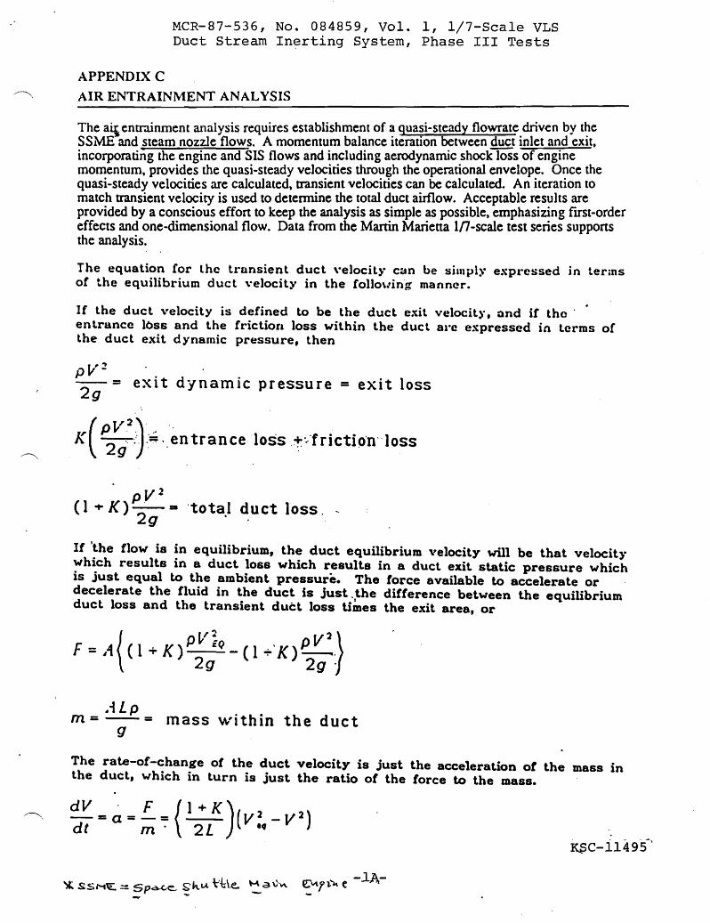
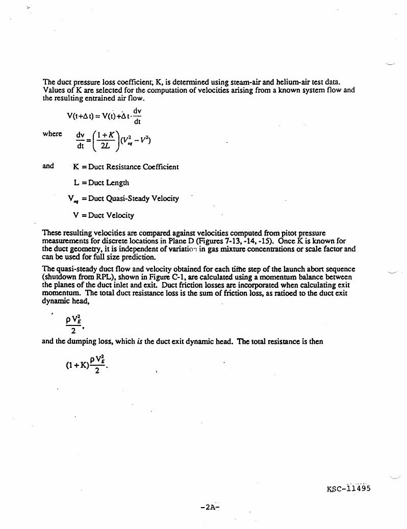
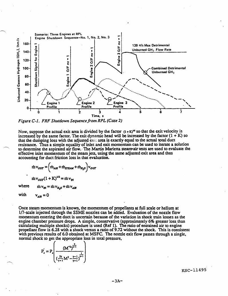
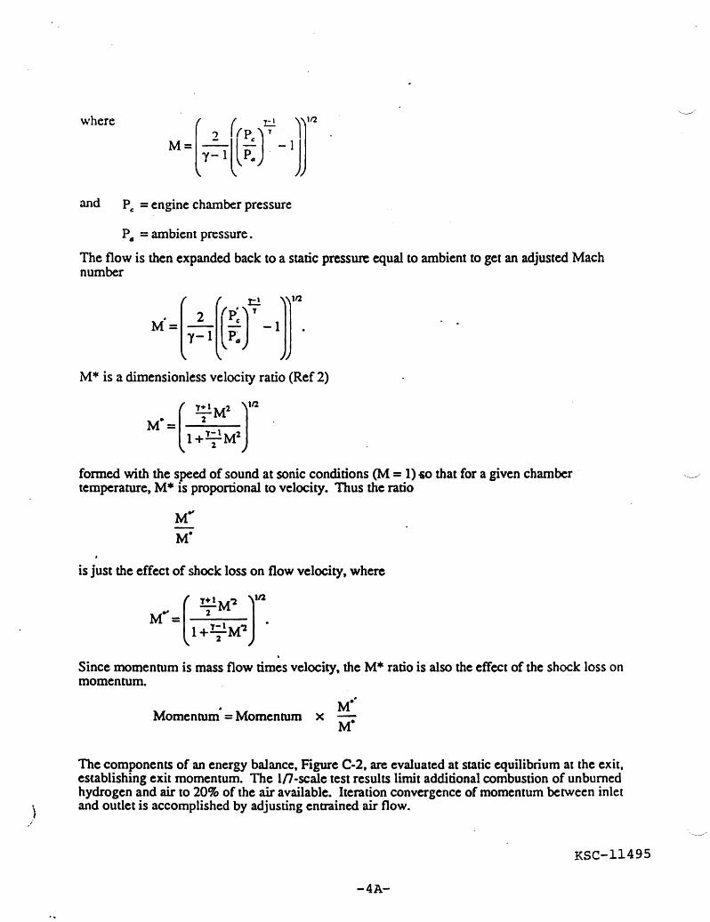
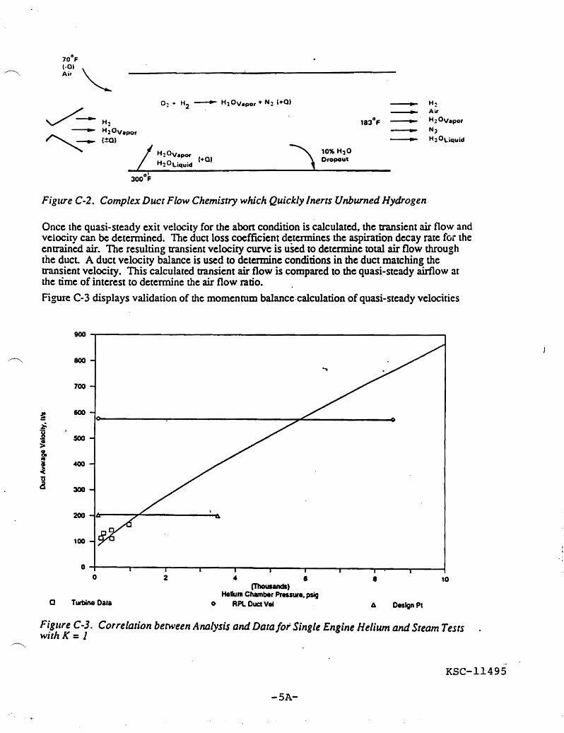
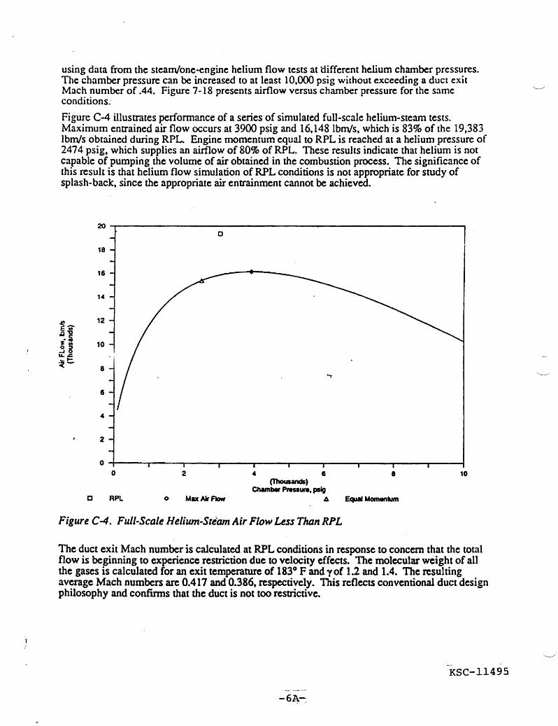
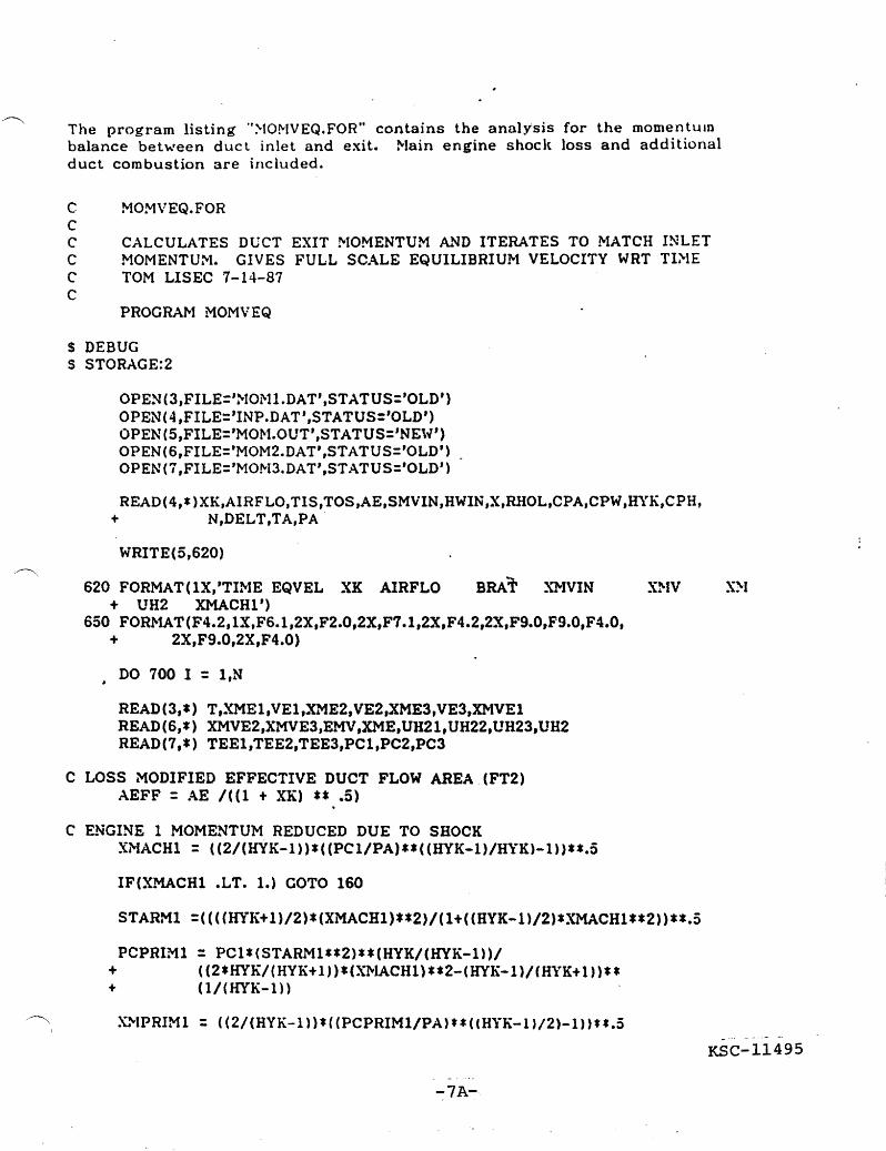
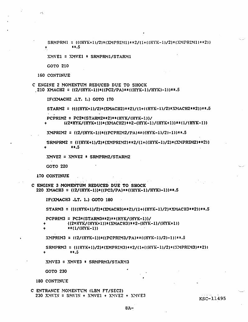
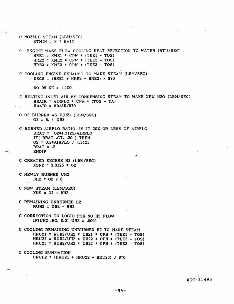
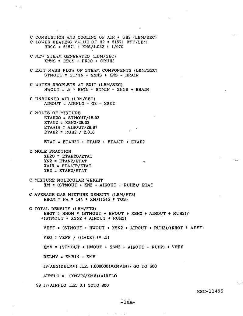
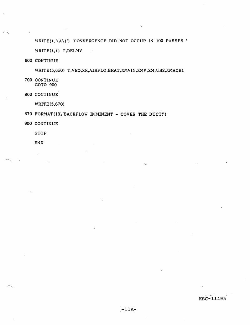
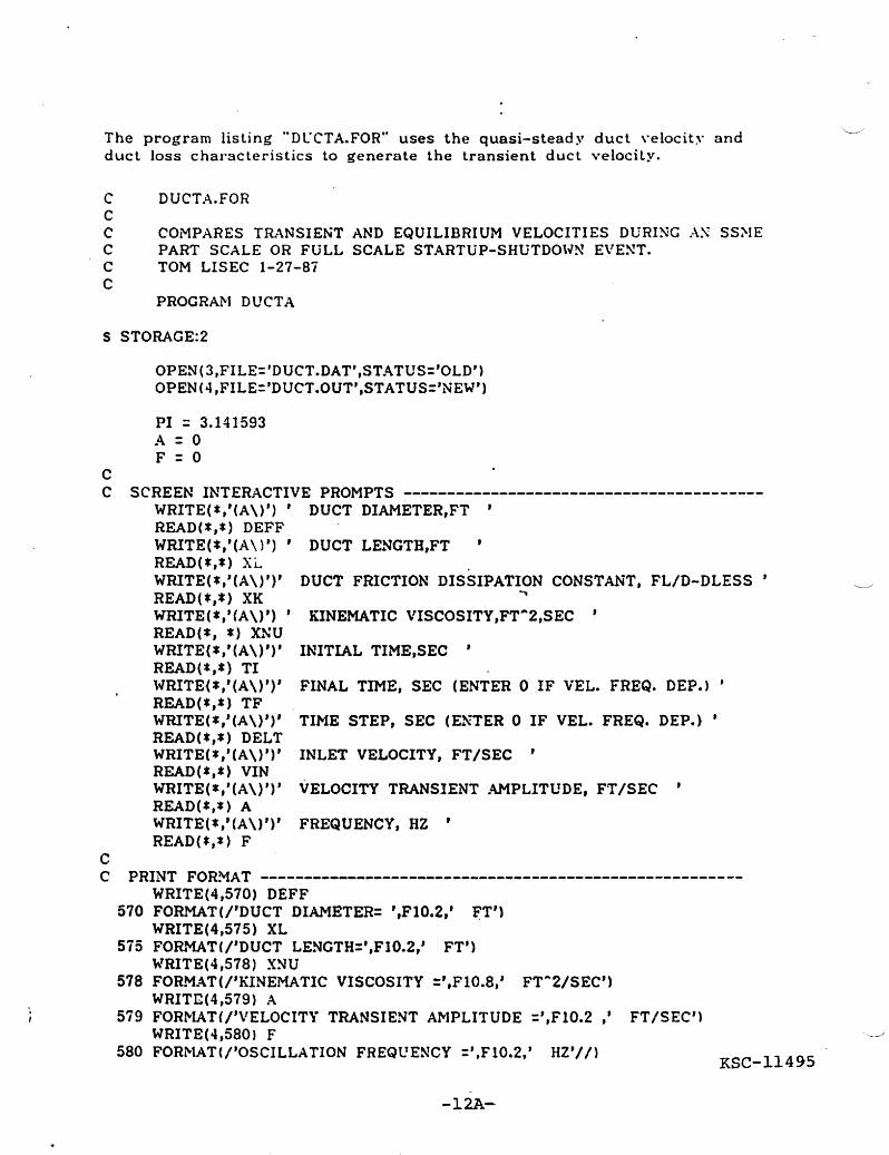
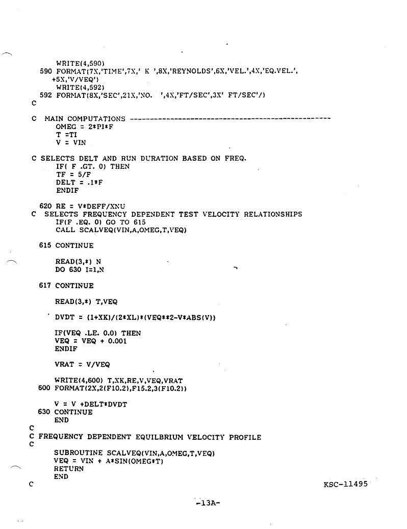
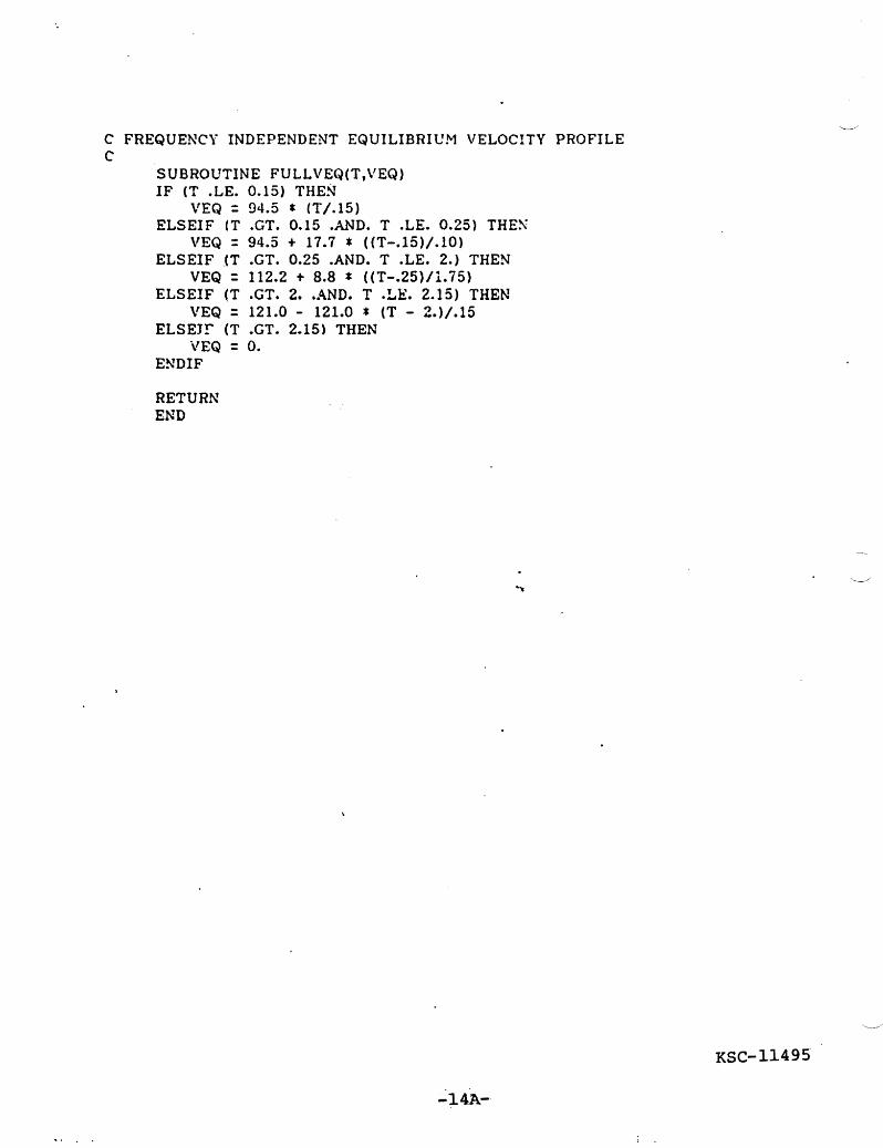
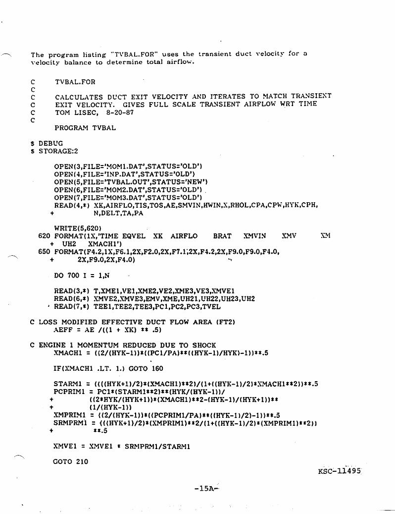
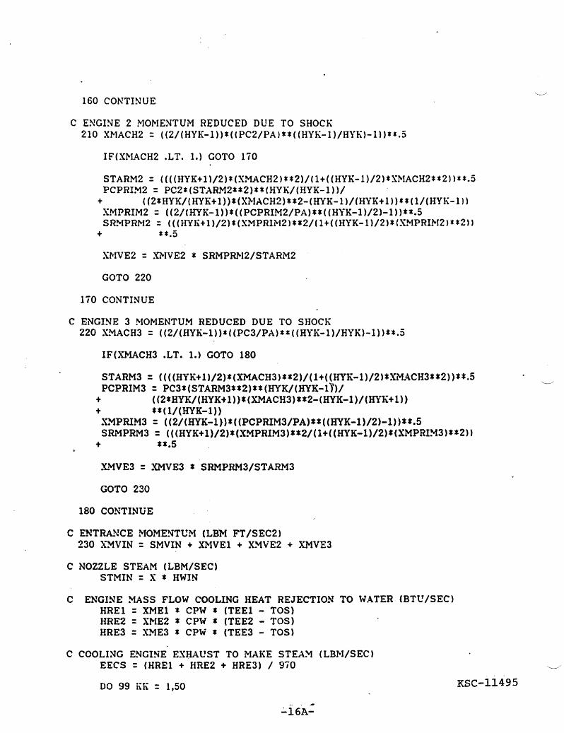
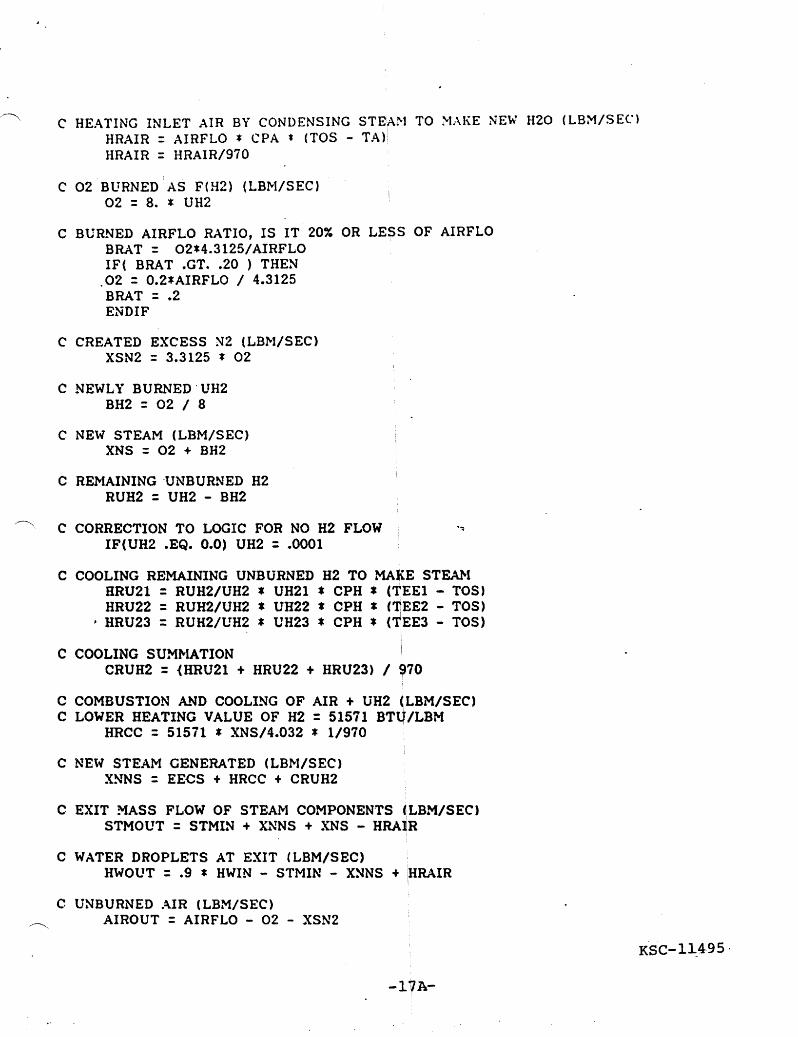
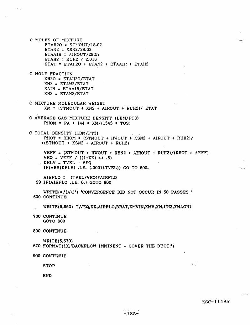
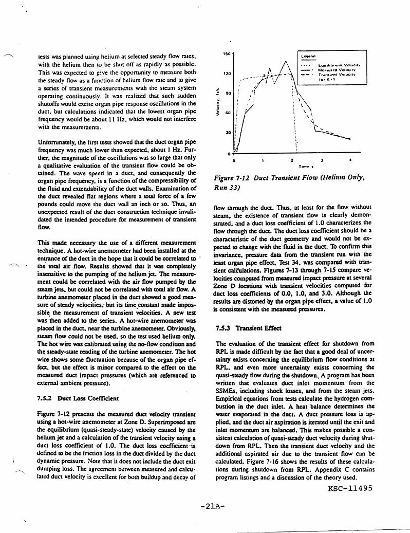
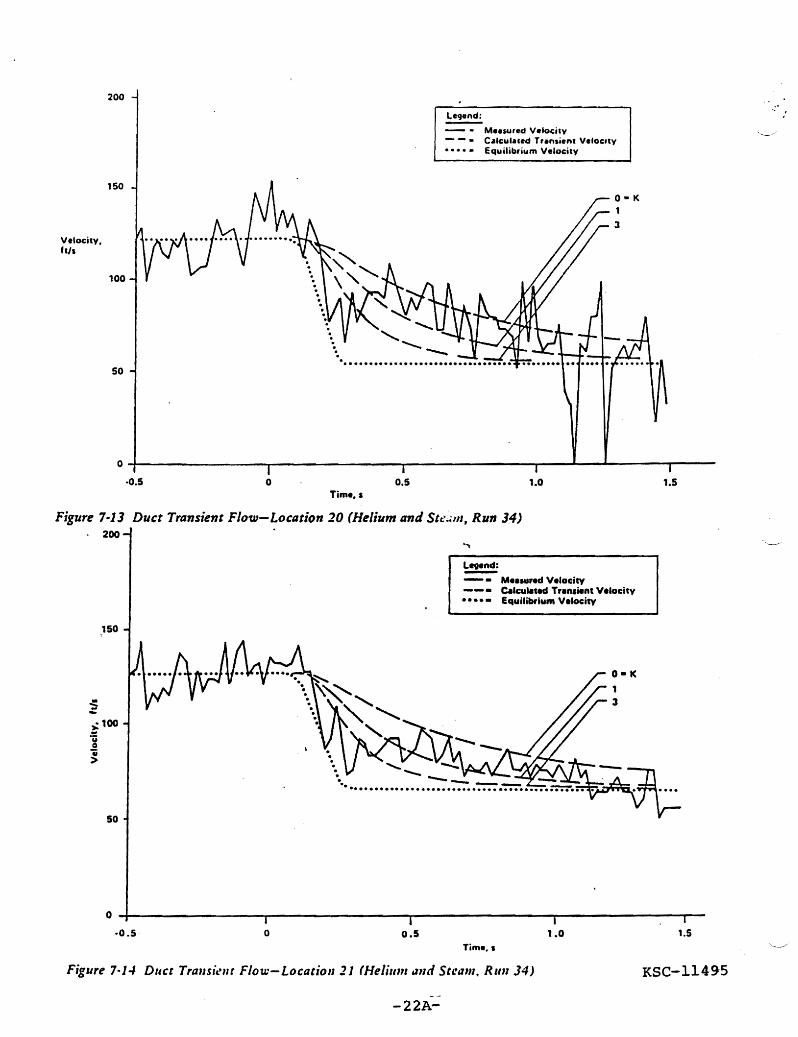
200
Mesured Velocity - - Cllculaed Trllnenc Velocity bullbullbullbullbull Equilibrium Velocity
150
Vlocity his
100
50
bullbullbullbullbullbullbullbullbullbull
O~-----------------r-----------------T----------------~----~--~------~------middot05 o 05 10 15
Tim bullbull s
Figure 7middot13 Duct Transient Flow-Location 20 (Helium and Stem Run 34) 200
Mred VDcity Calculated Trnsient VelDcity
bullbullbullbullbull Equilibrium Velocity
150
~oo
1 gt
50
o middot05 o 05 10 15
Figure 7middot1-1 DUCI Trallstllt Flow-Locatioll 21 (Helillm i111d Steam RlIlI 34) KSC-11495
-22Ashy
200
Legend
Musured VelocilY Calculated Transienl Velocity
bullbullbullbull - Equilibrium Velocity
Velocity hI
150
100
50
o ~----------------~-----------------r-----------------r------------------05 o 05 10 15
Time
Figure 1middot15 Duct Transient Flow-Location 23 (Helium and Steam Run 34) 22
20
18 Lnd
16 QubullbullimiddotStedy
Transient
14
8
amp
4
2
o~--------~------~------~--------~--------~--------~--------~---------o 2 4 6
Times
Figllre 7-16 Predicted Duct -lir Flow Jllri Sblltdotl1 [rom RPL -23Ashy
All of these calculations use a dUCI loss coefficient of 10 helium pressure on duct flow Figure 7-18 presenls calculashyThe 3spiraled air flow 3( RPL is calculated (0 be over lions tor 3ir flow as a funclion of helium pressure The air 19000 Ibis about six limes the mass How of the three low increases with helium pressure up to a value of 10000 SSMEs NOlO that the aspiraled air now does not have the psi Bccause general duct bacldlow could not occur unlil smooth character associated with lhe decrease ofduct velocshy even higher helium pressures were reached this strongly ity The air flow also refleclS me changing composition of suggests that the observed backflow must be a consequence me flow For instance from time = 0 to about 08 seconds of local flow conditions Specifically the proximity of the air flow increases to compensate for the sudden drop in No 1 engine to the west wall makes it probable that a engine flow locally separated flow is the cause of the splashback Apshy
pendix C Figure C-2 presents data correlation with analyshyThe paramecer of interest to me design of the steam inening ses which substantiate the calculation of airflow as a funcshysystem is the ratio of the transient air flow to the quasishy tion of helium pressure Slcady-state airflow Figure 7-17 presents this ratio for the entire shutdown process The design point for the SIS is the time at which the last engine reaches an oxidizer-to-fuel ratio of one the condilion for which combustion inside the engine ceases This design poim is reached at 40 seconds and the air flow ratio at this time is 2SS
754 Observed Splashback
During the highest helium pressure test (Run 35) a signifi cant water backtlow was observed Concern about the cause of this backtlow prompted an analysis of the effect of nozzle
35
3
Ibullbull
25
~ bullI 0 2
Cbull
bullc
i a
05
O~--------r-------~--------T-------~--------~-------r--------r--------r o 2 6 8
Time I
Figure 7-17 Predicted Air FloUJ Ratio durig ShltdowIl from RPL
KSC~~~49~
--24A-
260 17middotScl Entrained Air
240 SingI Engine Helium and Stam K-l
220
200
180
110
140
100
10
20
O~----~__----~----~------~----~------~----~------~----~------r-----~----~ o
IThCKIndU
Helium elMm Preuure paig
Figure 7-18 Predicted Effect ofHelium Pressure on Duct Air Entrtlinment
KSC-11495
-25Ashy
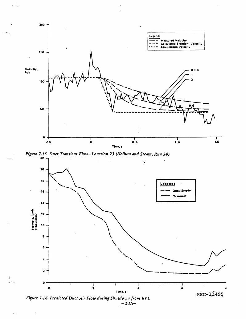
200
Legend
Musured VelocilY Calculated Transienl Velocity
bullbullbullbull - Equilibrium Velocity
Velocity hI
150
100
50
o ~----------------~-----------------r-----------------r------------------05 o 05 10 15
Time
Figure 1middot15 Duct Transient Flow-Location 23 (Helium and Steam Run 34) 22
20
18 Lnd
16 QubullbullimiddotStedy
Transient
14
8
amp
4
2
o~--------~------~------~--------~--------~--------~--------~---------o 2 4 6
Times
Figllre 7-16 Predicted Duct -lir Flow Jllri Sblltdotl1 [rom RPL -23Ashy
All of these calculations use a dUCI loss coefficient of 10 helium pressure on duct flow Figure 7-18 presenls calculashyThe 3spiraled air flow 3( RPL is calculated (0 be over lions tor 3ir flow as a funclion of helium pressure The air 19000 Ibis about six limes the mass How of the three low increases with helium pressure up to a value of 10000 SSMEs NOlO that the aspiraled air now does not have the psi Bccause general duct bacldlow could not occur unlil smooth character associated with lhe decrease ofduct velocshy even higher helium pressures were reached this strongly ity The air flow also refleclS me changing composition of suggests that the observed backflow must be a consequence me flow For instance from time = 0 to about 08 seconds of local flow conditions Specifically the proximity of the air flow increases to compensate for the sudden drop in No 1 engine to the west wall makes it probable that a engine flow locally separated flow is the cause of the splashback Apshy
pendix C Figure C-2 presents data correlation with analyshyThe paramecer of interest to me design of the steam inening ses which substantiate the calculation of airflow as a funcshysystem is the ratio of the transient air flow to the quasishy tion of helium pressure Slcady-state airflow Figure 7-17 presents this ratio for the entire shutdown process The design point for the SIS is the time at which the last engine reaches an oxidizer-to-fuel ratio of one the condilion for which combustion inside the engine ceases This design poim is reached at 40 seconds and the air flow ratio at this time is 2SS
754 Observed Splashback
During the highest helium pressure test (Run 35) a signifi cant water backtlow was observed Concern about the cause of this backtlow prompted an analysis of the effect of nozzle
35
3
Ibullbull
25
~ bullI 0 2
Cbull
bullc
i a
05
O~--------r-------~--------T-------~--------~-------r--------r--------r o 2 6 8
Time I
Figure 7-17 Predicted Air FloUJ Ratio durig ShltdowIl from RPL
KSC~~~49~
--24A-
260 17middotScl Entrained Air
240 SingI Engine Helium and Stam K-l
220
200
180
110
140
100
10
20
O~----~__----~----~------~----~------~----~------~----~------r-----~----~ o
IThCKIndU
Helium elMm Preuure paig
Figure 7-18 Predicted Effect ofHelium Pressure on Duct Air Entrtlinment
KSC-11495
-25Ashy
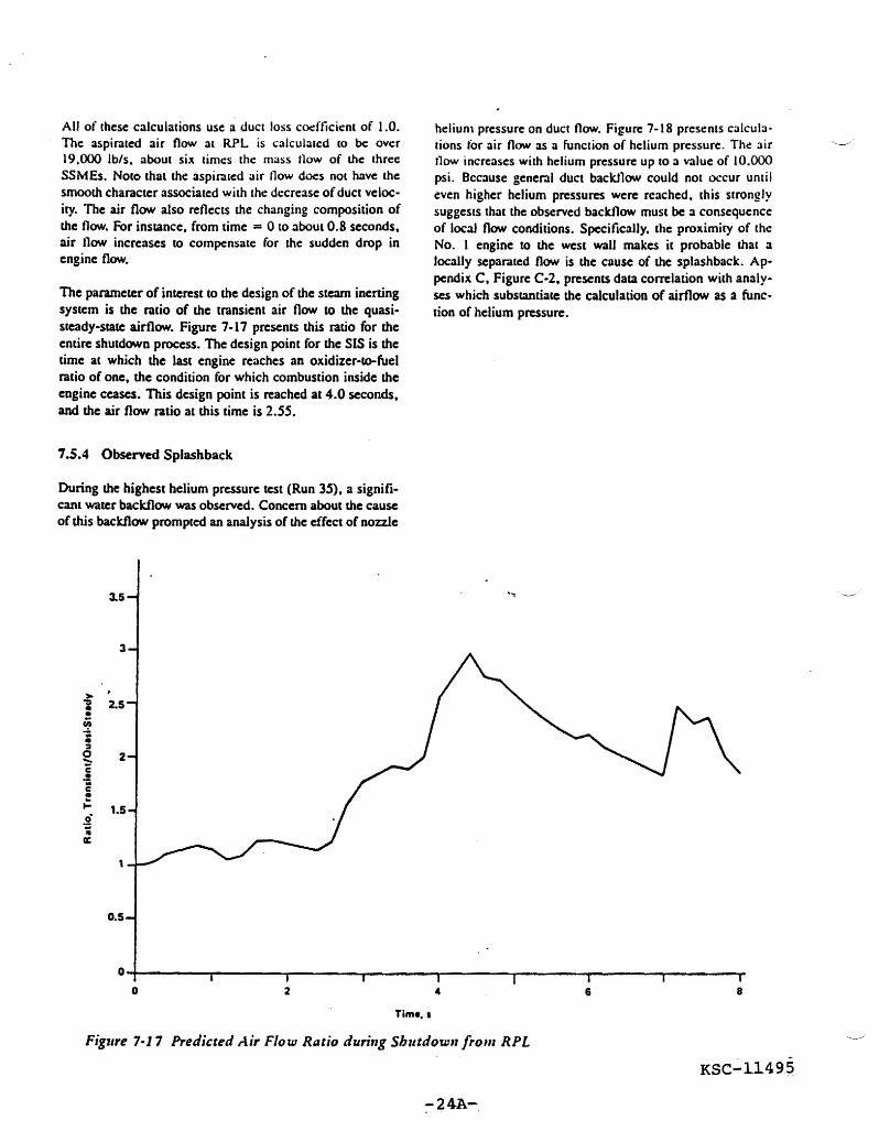
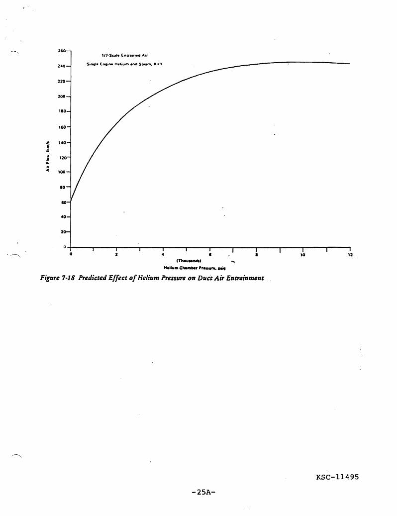
260 17middotScl Entrained Air
240 SingI Engine Helium and Stam K-l
220
200
180
110
140
100
10
20
O~----~__----~----~------~----~------~----~------~----~------r-----~----~ o
IThCKIndU
Helium elMm Preuure paig
Figure 7-18 Predicted Effect ofHelium Pressure on Duct Air Entrtlinment
KSC-11495
-25Ashy