NASA T - Old Dominion Universitymln/ltrs-pdfs/NASA-95-tm110164.pdf · While the standard C...
27
-
Upload
truongphuc -
Category
Documents
-
view
218 -
download
0
Transcript of NASA T - Old Dominion Universitymln/ltrs-pdfs/NASA-95-tm110164.pdf · While the standard C...

NASATechnicalMemorandum 110164
Manual for aWorkstation-basedGeneric Flight SimulationProgram (LaRCsim)Version 1.4
E. Bruce Jackson
Langley Research CenterHampton, Virginia
April 1995

Summary
LaRCsim is a set of ANSI C routines that implement a full set of equations ofmotion for a rigid-body aircraft in atmospheric and low-earth orbital ight, suitablefor pilot-in-the-loop simulations on a workstation-class computer. All six rigid-bodydegrees of freedom are modeled. The modules provided include calculations of thetypical aircraft rigid body simulation variables, earth geodesy, gravity and atmo-sphere models, and support several data recording options. Features/limitations ofthe current version include English units of measure, a 1962 atmosphere model incubic spline function lookup form, ranging from sea level to 75,000 feet, rotatingoblate spheroidal earth model, with aircraft C.G. coordinates in both geocentricand geodetic axes. Angular integrations are done using quaternion angular statevariables. Vehicle X-Z symmetry is assumed.
A copy of this software is available upon request to the author.
Introduction
Historically, six degree of freedom aircraft simulations have been performed onlarger minicomputers or mainframe computers due to limited processing speed anddata storage capability on smaller workstation and desktop computers. With theadvent of more powerful reduced instruction set computer (RISC) architecture, theprocessing capability of a desktop computer exceeds that of a supercomputer of adecade ago.
Simultaneously with the rise in popularity of workstation and desktop com-puters, the acceptance of UNIX-style operating systems has grown. This popularoperating system has brought with it the C programming language in which theoriginal UNIX kernal was written. While the standard C libraries lack some of themathematical procedures of FORTRAN, in which most digital aircraft models arewritten, it is still possible to make use of this powerful and portable language. Ab-stract data types, longer variable names, data structures, and recursion allow thesimulation architect to write maintainable and self-documenting software, with fullaccess, through standardized library routines, to operating system capabilities in anearly machine independent fashion.
Although not fully utilized in this version of LaRCsim, the popular X-Windowsfacility is easily manipulated in C. This provides for graphical operator/userinterface capabilities on any X capable terminal or personal computer terminalemulator (called a window server).
This version of LaRCsim utilizes a curses-based terminal interface, which willsupport almost all types of computer terminals. X-windows support is planned forlater versions of LaRCsim. Also supported is a Silicon Graphics GL workstationinterface that includes out-the-window scenery and heads-up display symbology.The pilot controls are provided through a mouse or, optionally, an analog-to-digitalinterface (driver code for the analog-to-digital interface is not included since thesoftware depends upon the choice of host processor and interface hardware.)
Output options include time history information in ASCII text tab-delimited,Dryden's GetData .ASC1, or Agile-Vu \.flt" format; a fourth option will writethe time history data into a text �le suitable for execution by one of several popularcontrols analysis software tools. Any global or static local variable can be recorded.The recording module uses debugger symbol to access static or global variables ata user-selected frequency. Speci�cation of variables to be recorded can be made atrun-time.
Overview
What is LaRCsim?
LaRCsim is a set of C routines that implement a full set of equations of motionfor a rigid-body aircraft in atmospheric and low-earth orbital ight. It is intended
1

to be used with additional, user-provided subroutines (either FORTRAN or C) thatdescribe the aerodynamics, propulsion system, and other ight dynamic elementsof a speci�c air vehicle. Once combined with the vehicle-speci�c routines, LaRCsimprovides a desktop- and/or cockpit-based near-real-time simulation of the vehiclefor engineering analysis and control law development.
The six rigid-body degrees of freedom are modeled. The modules providedinclude all of the kinematic relationships, most of the conventional output vari-ables, geodesy and atmospheric models, and a data recording option. Some fea-tures/limitations of the current version are as follows:
� English units of measure.� 1962 atmosphere model in cubic spline function lookup form, ranging from sealevel to 75,000 ft. Included in the model are density, speed of sound, and sigma.
� Rotating oblate spheroidal earth model, with aircraft C.G. coordinates in bothgeocentric and geodetic axes.
� Vehicle X-Z symmetry is assumed.� Quaternions are used in determining the angular orientation (although equiv-alent Euler angles are also calculated) to avoid the singularity at �90 degreespitch angle.
� Gravitational harmonic e�ects due to the earth's oblateness are modeled.� Modular design allows user to incorporate modi�ed atmosphere, turbulence, andsteady winds into the simulation.
� Rotating machinery e�ects are not modeled.
Origin and Purpose
LaRCsim was developed as part of an engineering ight simulation facility atNASA Langley Research Center that is used to debug aircraft ight control laws.This facility, known as Advanced Controls Evaluation Simulator (ACES), is usedin the Dynamics and Control Branch (DCB) and currently consists of a dual RISCprocesser Silicon Graphics Onyx computer with RealityEngine-2 graphics drivingan evaluation cockpit with throttles and a side stick hand controller.
The LaRCsim routines are used to provide appropriate aircraft dynamic re-sponses to ight control commands. The ight control laws may be written in C orFortran. The equations of motion are based upon work by McFarland in reference 1.The axis frames and sign conventions comply with the ANSI/AIAA recommendedpractice as outlined in reference 2; geodesy calculations use the relationships out-lined in reference 3, as well as a custom geocentric to geodetic conversion developedby the author. The atmosphere model is derived from data found in references 4and 5; other physical constants were obtained from references 6 and 7. LaRCsimitself is based upon FORTRAN routines originally developed by the author for theU. S. Naval Air Test Center (now the Naval Air Warfare Center) under a projectknown as CASTLE (see reference 8); these routines have ties back to the NASAAmes FORTRAN simulation routines known as BASIC, written by McFarland andothers.
It is intended that LaRCsim applications be capable of running both with acockpit and pilot in the loop as well as in terminal interactive and batch modes.This version includes both a generic display terminal and Silicon Graphics GL-basedkeyboard/mouse interfaces in addition to an external cockpit interface.
Changes from version 1.3
The ACES facility is still being developed, and LaRCsim continues to evolve.This release, version 1.4, di�ers from version 1.3 as follows:
� Six-degree of freedom trim capability has been added.
2

� The default settings �le has been renamed, and is automatically updated at theend of a session so LaRCsim \remembers" settings from the previous session.
� Initial conditions may be speci�ed at by a ag on the command line.� Time step and initialization ags are now passed to model routines.Additional information on these changes is available in the README �le,
provided in the software distribution. Please see this �le for more informationon what is required to adapt a version 1.3 simulation model to version 1.4. Thisreport details the requirements to implement a new version 1.4 simulation model.
Input �les
Default settings �le. LaRCsim is fairly self-contained, and does not require anyspecial supporting �les to run. It does, however, utilize one �le if it is present in thedefault directory: if present, a �le named .simname (also called the default settings�le) speci�es what parameters are to be recorded during the simulation run, whatparameters are to be used to trim the vehicle and what parameters are to be set tozero by the trim algorithm. The settings �le may specify a default initial conditionto which the model is initialized if no other initial condition �le is speci�ed on thecommand line. This �le is automatically updated at the end of a LaRCsim sessionto record any changes in these settings. A sample settings �le is shown in �gure 1.
In the present version of LaRCsim, the default settings �le contains four sectionsof information: previous simulation operation settings, a list of parameters to record,the default trim parameters, and the default initial conditions. These sections areindependent and may appear in any order.
The �rst few lines of the default settings �le demonstrates the use of a poundsign (#) as the �rst non-blank character to denote a comment line; comments canappear on any line (as long as the �rst non-blank character is a # ). Blank linesare ignored.
The third line in the �le is the �rst line that is used by LaRCsim: \sim" appearson a line by itself to indicated the beginning of a list of simulation options that werein force at the end of the last session. This line is followed by \0010" on the next lineby itself; this ag line indicates which version of syntax is used (presently version1.0) so that future version of LaRCsim will be able to recognize and use older input�les. The contents of this section indicate what type of �les to record at the endof the simulation session; the spacing with which to write the data �les, the endtime of the simulation; and the update rates for the model, screen refresh, and datarecording; and how long (in seconds) the data bu�er should be. In the examplegiven in �gure 1, a data �le in matrix format will be written when the simulationends. It will contain up to one hour's worth of simulation data, recorded at 20 Hzand every frame will be written to the data set. The model itself will run up to onehour, at 120 Hz, and the video screen (or terminal screen) will be updated at 30frames per second.
In the next section, \record" appears on a line by itself to indicate the beginningof a list of parameters to be recorded during the simulation session. The next sixlines are parameter declarations; these six parameters, if successfully located inthe debugger symbol tables, will be added to 19 prede�ned variables and recordedduring the simulation session.
The �rst three declaration lines are examples of how to specify scalar parameters.Note that these declarations are local variables to each routine. LaRCsim, by wayof compiler-provided symbol tables, can locate and track the value of any localor global variable, but the variables must be static variables, declared as such atthe top of each function. If the variables are automatic (i.e., not static), thenthe variable is de�ned only as long as the program is executing that function;thus, LaRCsim is unable to track automatic variables. The third declaration, ofvariable forward mu in function navion gear, is actually an automatic variable (in
3

# .navion created at 950406 22:57:12 by bjax#============================== sim
sim0010
write av 0write mat 1write tab 0write asc1 0write spacing 1end time 3600.000000model hz 120.000000term update hz 30.00000data rate 20.000000buffer time 3600.0000
end
#============================== record
record0010
aero elevatoraero ailerongear forward mu* generic .f gear v[0]* generic .f gear v[1]* generic .f gear v[2]
end
#============================== trim
trim0010controls: 3
# module parameter min val max val pert size* generic .euler angles v[1] -7.853981E-01 7.853981E-01 1.000000E-02aero long trim -1.000000E+00 1.000000E+00 1.000000E-02* cockpit .throttle pct 0.000000E+00 1.000000E+00 1.000000E-02
outputs: 3# module parameter trim criteria
* generic .omega dot body v[1] 5.000000E-05* generic .v dot body v[0] 5.000000E-04* generic .v dot body v[2] 5.000000E-04
end
#============================== init
init0010continuous states: 22
# module parameter value* generic .geodetic position v[0] 2.374953E-04* generic .geodetic position v[1] 7.714288E-07* generic .geodetic position v[2] 1.099708E+01* generic .v local v[0] 1.740701E+02* generic .v local v[1] 1.522121E+03* generic .v local v[2] -3.972784E+00* generic .euler angles v[0] -1.481027E-04* generic .euler angles v[1] 1.127979E-01* generic .euler angles v[2] 2.089291E-03* generic .omega body v[0] 5.395570E-06* generic .omega body v[1] 0.000000E+00* generic .omega body v[2] -2.788522E-05* generic .earth position angle 0.000000E+00* generic .mass 8.547270E+01* generic .i xx 1.048000E+03* generic .i yy 3.000000E+03* generic .i zz 3.530000E+03* generic .i xz 0.000000E+00* generic .d cg rp body v[0] 0.000000E+00* generic .d cg rp body v[1] 0.000000E+00* generic .d cg rp body v[2] 0.000000E+00aero long trim -1.365538E-03
discrete states: 0# module parameter valueend
Figure 1. A sample default settings �le.
the example simulation), and thus LaRCsim will complain when it reads this input�le and attempts to locate forward mu for the �rst time.
A local static variable is speci�ed by the name of the function or subroutine inwhich it exists (e.g. aero or navion gear) and the name of the variable. Case isimportant. Elevator is not the same variable as elevator.
4
The next three lines are examples of global variables; these are variables thathave been declared outside the scope of a function. They are identi�ed to LaRCsimas global by use of the * in place of a function name.
These last three lines also demonstrate the capability of LaRCsim to parse andlocate elements of complex data structures; here, the elements of the landing gearforce vector, f gear v, itself a part of the global data structure generic , will beadded to the list of variables to record. The syntax for non-scalar data elementsfollows that of ANSI C. Arrays are all zero-index-based, as in C (unlike FORTRAN).
The end word must appear on a line by itself to delimit the list of recordingvariables that began with record.
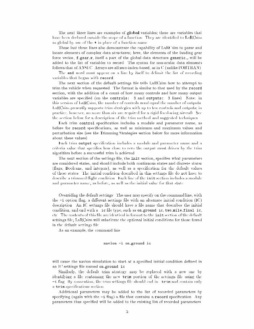
The next section of the default settings �le tells LaRCsim how to attempt totrim the vehicle when requested. The format is similar to that used by the recordsection, with the addition of a count of how many controls and how many outputvariables are speci�ed (on the controls: 3 and outputs: 3 lines). Note: inthis version of LaRCsim, the number of controls must equal the number of outputs.LaRCsim presently supports trim strategies with up to ten controls and outputs; inpractice, however, no more than six are required for a rigid �xed-wing aircraft. Seethe section below for a description of the trim method and suggested techniques.
Each trim control speci�cation includes a module and parameter name, asbefore for record speci�cations, as well as minimum and maximum values andperturbation size (see the Trimming Strategies section below for more informationabout these values).
Each trim output speci�cation includes a module and parameter name and acriteria value that speci�es how close to zero the output must driven by the trimalgorithm before a successful trim is achieved.
The next section of the settings �le, the init section, speci�es what parametersare considered states, and should include both continuous states and discrete states( ags, Booleans, and integers), as well as a speci�cation for the default valuesof these states. The initial condition described in this settings �le do not have todescribe a trimmed ight condition. Each line of the init section includes a moduleand parameter name, as before, as well as the initial value for that state.
Overriding the default settings. The user may specify on the command line, withthe -i option ag, a di�erent settings �le with an alternate initial condition (IC)description. An IC settings �le should have a �le name that describes the initialcondition, and end with a .ic �le type, such as on ground.ic, two mile final.ic,etc. The contents of this �le are identical in format to the init section of the defaultsettings �le; LaRCsim will substitute the optional initial conditions for those foundin the default settings �le.
As an example, the command line
navion -i on ground.ic
will cause the navion simulation to start at a speci�ed initial condition de�ned inan IC settings �le named on ground.ic.
Similarly, the default trim strategy may be replaced with a new one byidentifying a �le containing the new trim portion of the settings �le using the-i ag. By convention, the trim settings �le should end in .trim and contain onlya trim speci�cations section.
Additional parameters may be added to the list of recorded parameters byspecifying (again with the -i ag) a �le that contains a record speci�cation. Anyparameters thus speci�ed will be added to the existing list of recorded parameters.
5

In the present version of LaRCsim, only one settings �le may be speci�ed atrun time; it is possible to combine several settings �le into a single �le, and specifythat �le name at run time to achieve the desired set of trim parameters, recordedvariables, and initial conditions.
Optional search path and redirection. At startup, LaRCsim will search thedirectories listed in an environment variable LARCSIMPATH, if it is de�ned, to �ndboth the default settings �le (e.g. .navion) and any speci�ed settings �le �les (e.g.on ground.ic). LaRCsim will use the �rst occurance of these �les discovered in thepath of directories speci�ed by LARCSIMPATH. The variable LARCSIMPATH should bea colon-separated list of directories, similar to standard UNIX PATH environmentvariables. If LARCSIM is unde�ned, only the default directory will be searched to�nd the settings �le.
A settings �le may contain a line beginning with `@'; this indicates to LaRCsiman additional �le that should be parsed. For example, the default settings �le forthe terminal version of a simulation (e.g. .navion term) could contain the singleline, @.navion; LaRCsim would interpret this to mean the contents of .navionshould be parsed instead of .navion term. (Note: .navion term should be set toread-only to prevent it from being overwritten at the end of the LaRCsim session.)
The �le pointed to by the indirection ag `@' could itself contain an additionalindirection ag; caution should be used to avoid circular references.
Output �les
.simname This default settings �le, if it does not already exist, is created at the endof each simulation session and will contain the default values for recordparameters, trim controls, and initial conditions. If the default settings �lealready exists and is not write-protected it will be replaced with a new copy.
run.flt This �le, if requested with the -a ag, will be generated at the end of asession and will contain a time history of each recorded parameter in Agile-Vu format.
run.m This �le, if requested with the -r ag, will be generated at the end of asession and will contain the time history information in matrix notation,suitable for use as a script in one of the popular control system design andanalysis products.
run.asc1 This �le, if requested by use of the -x command line switch, wil be generatedat the end of a session and will contain the time history information in aformat understood by the Dryden Flight Research Center's GetData andXPlot tools.
run.dat This �le, if requested with the -t command line switch, will contain ASCIItab-delimited columns of the recorded data; the �rst line contains the namesof the parameters included. This format may be useful for importing timehistory data into spreadsheet or other charting programs.
Running a LaRCsim Example
Compiling LaRCsim
Building LaRCsim from the distribution is straightforward:
1. De�ne an environment variable, LARCSIM, to point to the source directory forthe main LaRCsim routines. This should probably be done in the user's .login�le (Example: setenv LARCSIM /aces/larcsim/v014)
2. Change the default directory to $LARCSIM.3. Enter the command \make." This will:
a. create a new object library �le, libls.ab. compile all of the LaRCsim source �les
6
c. put all the generated object �les in the libls.a archive library
The object archive library libls.a only needs to be rebuilt after a LaRCsimmodulehas been modi�ed.
Compiling and building the example simulation
Once the libls.a �le has been built in the $LARCSIM directory, move to thedirectory containing the aircraft �les (in the case of the example simulation, moveto the navion directory).1. Enter the command \make" (for Silicon Graphics-based simulations) or \make
term" for a terminal-based simulation. This will compile all the navion source�les and link them together to form the executable simulation program navion
(for Silicon Graphics-based simulations, or navion term, for a terminal-basedsimulation).
2. If desired, create a default settings �le in the format described above. It shouldbe named .simname, where simname is the name of the executable simulationprogram.
Running the example simulation program
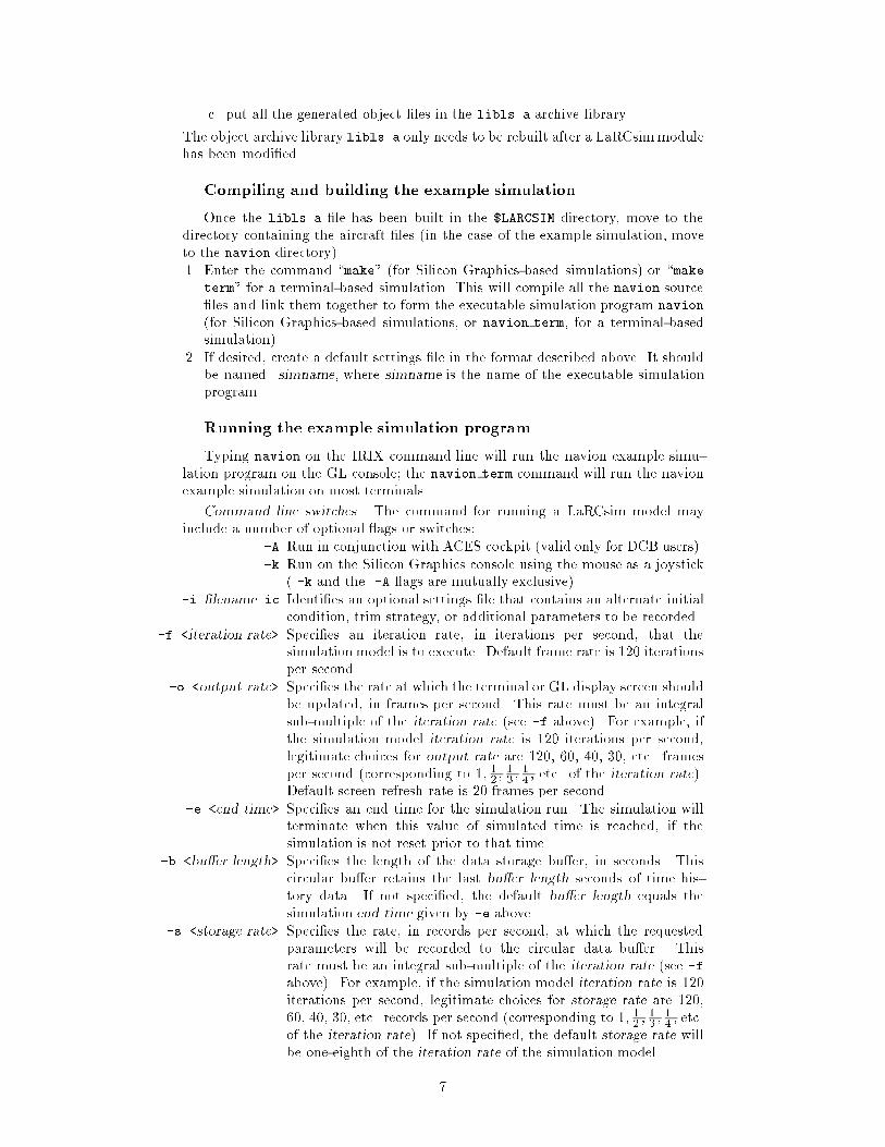
Typing navion on the IRIX command line will run the navion example simu-lation program on the GL console; the navion term command will run the navionexample simulation on most terminals.
Command line switches. The command for running a LaRCsim model mayinclude a number of optional ags or switches:
-A Run in conjunction with ACES cockpit (valid only for DCB users).-k Run on the Silicon Graphics console using the mouse as a joystick
( -k and the -A ags are mutually exclusive).-i �lename.ic Identi�es an optional settings �le that contains an alternate initial
condition, trim strategy, or additional parameters to be recorded.-f <iteration rate> Speci�es an iteration rate, in iterations per second, that the
simulation model is to execute. Default frame rate is 120 iterationsper second.
-o <output rate> Speci�es the rate at which the terminal or GL display screen shouldbe updated, in frames per second. This rate must be an integralsub-multiple of the iteration rate (see -f above). For example, ifthe simulation model iteration rate is 120 iterations per second,legitimate choices for output rate are 120, 60, 40, 30, etc. framesper second (corresponding to 1; 1
2; 13; 14; etc. of the iteration rate).
Default screen refresh rate is 20 frames per second.-e <end time> Speci�es an end time for the simulation run. The simulation will
terminate when this value of simulated time is reached, if thesimulation is not reset prior to that time.
-b <bu�er length> Speci�es the length of the data storage bu�er, in seconds. Thiscircular bu�er retains the last bu�er length seconds of time his-tory data. If not speci�ed, the default bu�er length equals thesimulation end time given by -e above.
-s <storage rate> Speci�es the rate, in records per second, at which the requestedparameters will be recorded to the circular data bu�er. Thisrate must be an integral sub-multiple of the iteration rate (see -f
above). For example, if the simulation model iteration rate is 120iterations per second, legitimate choices for storage rate are 120,60, 40, 30, etc. records per second (corresponding to 1; 1
2; 13; 14; etc.
of the iteration rate). If not speci�ed, the default storage rate willbe one-eighth of the iteration rate of the simulation model.
7
-a <�lename> Speci�es that an Agile-Vu compatible \. t" �le is to be written atthe end of the session. Default �lename is run.flt. If this optionis the last one on the command line, a �lename must be speci�ed.
-t <�lename> Speci�es that a tab-delimited ASCII listing of time history data bewritten at the session. Default �lename is run.dat. If this optionis the last one on the command line, a �lename must be speci�ed.
-x <�lename> Speci�es that a GetData/X-Plot compatible \.asc1" �le is to bewritten at the end of the session. Default �lename is run.asc1. Ifthis option is the last one on the command line, a �lename mustbe speci�ed.
-r <�lename> Speci�es that a matrix manipulation software compatible .m �le isto be written at the end of the session. Default �lename is run.m.If this option is the last one on the command line, a �lename mustbe speci�ed.
-d Speci�es that the run allow interactive debugging; this preventsscheduling of timer interrupts and forces the GL display into single-bu�er mode. This switch is probably not of great use to the typicaluser.
GL console operation. The command navion -k will bring up the out-the-window view, on the SGI console, with a heads-up display (HUD) overlay, andallow the user to maneuver the aircraft using the mouse and keyboard. The mousemovement simulates a control stick: push forward to move the stick forward, left toroll left, etc.
When the simulation �rst comes up, the aircraft is placed in the speci�ed initialcondition and the display will indicate the simulation is paused (on a GL display,this is indicated by the HUD symbology showing up in a red color). At this pointthe simulation may be trimmed (using the `t' key) or put into operation (with the`p' key). A trim may be requested at any time during a run by use of the `t' key;this allows the vehicle to be own to an interesting point of the sky and retrimmed.A successful trim will cause the current ight conditions to be remembered as thenew initial condition.
At any point, the `r' key will reset the simulation to the last remembered initialcondition, allowing repeated landing attempts, for example.
The simulation may be paused at any point by use of the `p' key to togglebetween pause and run modes. Data is recorded in run mode and during trimattempts.
The simulation session will last for up to 60 minutes; a longer period of timemay be speci�ed on the command line as a parameter for the -e option (see theprevious section for information on various command line options).
Pressing the escape key causes the simulation to terminate, and any recordeddata will be written to the requested output �les.
Display terminal operation. The command navion term will operate the samesimulation, but does not use a mouse or provide GL graphics. Instead, a simpleinstrument panel is presented on the user's terminal screen and several keyboardkeys are pressed into service for ight controls. Figure 2 shows the screen used inLaRCsim version 1.4, with ight control keys indicated. No rudder command isavailable in this version.
External cockpit operation. The command navion -A will operate the samesimulation, but LaRCsim will call the external cockpit interface routine to providecontrol stick, rudder pedal, and throttle positions, as well as pause and reset buttons.Most keyboard commands will still operate.
Note for DCB users: in the ACES cockpit, the upper red button on the handgripresets the simulation, and the thumb button pauses the simulation.
8

L a R C S I M navion term 0:00:00.0
Mach 0.007 Psi 0.1 NZ-G 0.997
KEAS 4.3 Thet 0.4 Alt 4 Alpha 0.42
Throt 0 % Phi 0.0 Hdot 0.000 Beta 0.03
Elevator 0.00 Aileron 0.00 Rudder 0.00
stick
i
throttle quit
|
-a +s j -k- l <ESC>
|
<
Figure 2. Terminal mode display
Trimming strategies
The trim algorithm, new to this version of LaRCsim, uses up to ten user-speci�ed\controls" to drive a like number of \outputs" to values near zero. LaRCsim alsoforces pitch rate to zero prior to each trim attempt, so trimmed turns are notcurrently possible. Steady-heading sideslip trims, however, are possible and havebeen demonstrated. On-ground longitudinal trims are also supported.
The current mechanism to specify (and modify) the trimmethod requires editingthe default settings �le, or specifying a settings �le containing a di�erent set of trimcontrols and outputs by use of the -i ag on the command line. Listed beloware examples of trim speci�cations that have been tested and used successfully inLaRCsim simulations at Langley Research Center.
In- ight longitudinal trim. In this example, pitch attitude, throttle, and a localvariable in the aerodynamics module called \long trim" are used to zero out theaccelerations in pitch and body-X and -Z axes:
trim
0010
controls: 3
# module parameter min val max val pert size
* generic .euler angles v[1] -0.785 0.785 1.0E-02
aero long trim -1.0000E+00 1.0000E+00 1.0000E-02
* cockpit .throttle pct 0.0000E+00 1.0000E+00 1.0000E-02
outputs: 3
# module parameter trim criteria
* generic .omega dot body v[1] 5.0000E-05
* generic .v dot body v[0] 5.0000E-04
* generic .v dot body v[2] 5.0000E-04
end
On-ground trim. With this strategy, two controls (pitch attitude and altitude)are used to obtain zero pitch and vertical acceleration, regardless of the aircraft'svelocity or heading:
trim
0010
controls: 2
# module parameter min val max val pert size
* generic .euler angles v[1] -0.785 0.785 1.0E-02
9

* generic .geodetic position v[2] 0 30 0.0001
outputs: 2
# module parameter trim criteria
* generic .omega dot body v[1] 5.0000E-05
* generic .v dot local v[2] 5.0000E-04
end
Steady-heading sideslip trim. In this strategy, three pilot control trim variablesare used, along with throttle, pitch attitude, and heading angle to achieve zeroaccelerations in angular and local velocities:
# this trim is for steady-heading sideslip, where
# sideslip is given by local velocities.
trim
0010
controls: 6
# module parameter min val max val pert size
subsystems longtrim -3.0000E+01 3.0000E+01 3.0000E-02
* generic .euler angles v[1] -0.5 0.5 1.0000E-03
* cockpit .throttle pct 0.0000E+00 1.0000E+00 1.0000E-03
subsystems lattrim -10 10 0.01
subsystems pedtrim -10 10 0.01
* generic .euler angles v[0] -0.5 0.5 0.001
outputs: 6
# module parameter trim criteria
* generic .omega dot body v[0] 5.0000E-05
* generic .omega dot body v[1] 5.0000E-05
* generic .omega dot body v[2] 5.0000E-05
* generic .v dot local v[0] 5.0000E-04
* generic .v dot local v[1] 5.0000E-04
* generic .v dot local v[2] 5.0000E-04
end
Creating a New Aircraft Simulation
Mandatory routines
A new simulation model must provide, as a minimum, an aerodynamics routinewith an entry point labeled aero(). The source code is usually kept in a �le namedafter the speci�c vehicle, e.g. navion aero.c. In addition, a complete vehiclemodel would include engine(), subsystems(), inertias(), and gear() routines,although stub routines are provided for these.
Inputs to these routines come from the GENERIC global variable structure, forwhich useful aliases are provided in the ls generic.h header �le (see Appendix A).The more sophisticated models will undoubtedly create an aircraft-speci�c set ofglobal variables; the use of a struct or COMMON is recommended to share these globalspeci�c variables between simulation components. Interface to the simple keyboard,mouse and/or ACES cockpits is available through the COCKPIT data structure.
The expected outputs from aero() are simply the aerodynamic forces andmoments about the reference point, in lbs and ft-lbs, respectively, being storedin the F aero v and M aero v vectors (scalar names F X aero, F Y aero, F Z aero,M l aero, M m aero, and M n aero).
Likewise, the outputs from any engine() or gear() routines should be storedin the F engine v, M engine v, F gear v, and M engine v vectors as appropriate.Refer to the example simulation for samples of how to do this.
If desired, the LaRCsim user may craft an inertias() routine to keep track offuel burn (using an aircraft speci�c fuel ow parameter provided from engine())
10
and adjust the inertia properties and center of gravity location values kept inGENERIC: Mass, I xx, I yy, I zz, I xz, and vector quantity D cg rp body v (thelocation of the center of gravity, measured from the reference point, in body axis);for most simulation studies of an engineering nature, the fuel quantity is a constantthat can be, along with mass properties and C.G. location, be set at initialization(through user routine model init(), or through a settings �le.).
The user must have a model init() routine, which is called before eachsimulation run, to set certain parameters. See the section below for a list ofnecessary parameters. Failure to set certain parameters will lead to an immediatedivide by zero error, or unreasonable dynamic response of the simulation.
The subsystems() hook allows control system models, navigation systemmodels, sensor models, autopilots, etc. to be included in the more elaboratesimulations. These routines will likely use some of the parameters provided inGENERIC and get other inputs from and store outputs to user-de�ned commonmemory structure(s).
Mandatory parameters
The following is a list of the variables for which the user-supplied vehicle routinesmust provide reasonable values:
Mass vehicle inertial properties;I xx these must be non-zeroI yy
I zz
I xz
D pilot rp body v pilot location w.r.t. reference pointD cg rp body v C. of Grav. location w.r.t. reference pointF aero v aero forces, body axesF engine v engine forces, body axesF gear v gear forces, body axesM aero v aero moments, body axes, about ref. pt.M engine v engine moments, body axes, about ref. pt.M gear v gear moments, body axes, about ref. pt.Runway altitude location of threshold of runway of interestRunway latitude
Runway longitude
Runway heading
These values may be initialized once, in the model init() function, or may becalculated each frame, in a procedure called by ls model(). The mass propertiesmust by non-zero to avoid mathematical errors.
The following variables should be speci�ed in model init() to the appropriateinitial conditions; they are thereafter calculated by the EOM routines:
Geodetic position v geodetic position in radiansfeetEuler angles v aircraft attitude (�; �; ), radiansV local v center of gravity velocities, in ft/sOmega body v body axis rates, in rad/s
where geodetic position is latitude, longitude, and altitude above sea level. Thefollowing variables may be set by the user routines if desired:
V local airmass v airmass velocity: steady windV local gust v body axis turbulence
11

Support for FORTRAN routines
Existing FORTRAN routines can be interfaced to LaRCsim through use of\wrapper" routines that translate between existing FORTRAN COMMON data struc-tures and the GENERIC and other LaRCsim data structures. It is possible to writeFORTRAN versions of aero(), engine(), inertias(), etc., but the reader is en-couraged to write new models in C (or even C++) for maintainability and compat-ibility reasons.
The secret to writing these \wrapper" routines is to realize that, at least inIRIX, FORTRAN entry points and commons appear (from the C side) as havingthe same name that they do in FORTRAN, but in lowercase and with an underscore(` ') appended, and vice-versa. Thus, a FORTRAN COMMON structure named SIMPARwill appear to the C language routine as a global variable named simpar (it mustbe declared as an external global structure in the C routine or header �le). Likewise,a FORTRAN subroutine declared as SUBROUTINE PLSURF can be called from a Cprogram as plsurf (). Consult the documentation for each particular operatingsystem for more information on how to develop a \wrapper" for an implementationon that system.
When the real-time loop is entered, the routines speci�ed in ls model() arecalled once per loop. The user is expected to replace the simple aero() andengine() routines provided in this package with more realistic aerodynamic andpropulsion system models. These models should calculate, based upon the currentMach, altitude, angle of attack, etc. the appropriate forces and moments due toaerodynamics, engines, and perhaps landing gear, if appropriate. These forces andmoments are to be provided in units of lbs and ft-lbs, in the X-Y-Z body axis system(positive indicates forward, right, and down, respectively) acting at the prede�nedreference position. If fuel consumption or weapon drops are to be simulated, aninertias() routine should be added, and the values of Mass, I xx, I yy, I zz
and I xz should be updated in each loop. Center of gravity movement should bere ected in updates to the D cg rp body v vector as well. It is also possible tochange runway location during simulation operation, if appropriate; the code toprovide this capability is not included in the present LaRCsim version, however.
Function Data Interpolation
Overview. Mathematical descriptions of the aerodynamics of most ight vehiclesusually include non-linear elements, such as the stall \break" characteristic exhib-ited by straight �xed-wing aircraft at higher angles of attack. Other aerodynamicproperties exhibit even more pronounced non-linearities with respect to angles ofattack, sideslip, Mach number, control surface de ection and other \independent" ight conditions. Other components of a ight vehicle model, such as propulsionsystems and control law gain tables, often need to represent a very non-linear pa-rameter in some fashion.
Many ways have been developed in previous years to represent these non-linearfunctions, including specialized mechanical analogues and electrical circuits. Inpresent ight simulators these functions are represented through special-purposesoftware. To save memory, early software-based functions were generated usingpolynomials to approximate the non-linear characteristics of the actual airplane.As memory became less expensive, small tables of numbers were stored andthen interpolated at run time. The present industry practice is to use largeamounts of memory to store multi-dimensional tables; a return to polynomialrepresentation may be underway to generate models that are mathematicallysmooth (see reference 10). The atmosphere model developed for LaRCsim usesa combination of these techniques; it represents atmospheric properties by use of atable, based upon altitude, of the coe�cients of a set of cubic spline functions that
12

provide smoothly varying curves that agree with the original atmosphere model atthe \knots".
To provide a general, C-based function generation capability, the ls funcgen.c
module was developed. This simple code makes use of an object paradigm torepresent the function tables and a recursive C-routine to perform the interpolationalong each dimension. This particular solution is, in the opinion of the author,elegant in its object-oriented design, recursiveness and the capability to handlefunction sets of unlimited size and dimension; it is, on the other hand, a littledi�cult to understand, and not as fast as an in-line, non-recursive, FORTRANroutine used for comparision.
To become really useful, a set of tools to generate the function data code for aparticular simulation would be nice and may become available in a later version ofLaRCsim.
Terminology. The following terms are used to describe the function generationroutine:
Breakpoint data set A monotonically increasing vector of real numbers thatrepresent the values of an independent variable for whichthe dependent function is known and tabulated.
Dependent variable The value of the function, or the return value from thefunction generation subroutine. Known values of thedependent variable for speci�c values of the independentvariable(s) upon which it depends are provided by theuser in the form of data tables; the routines describedin this section provide linearly interpolated values of thedependent variable for an arbitrary set of independentvariable values.
Dimension Each dimension of a data table represents an independentvariable upon which the dependent variable, representedas points in the function table, are based.
Function table A multi-dimensional table of dependent variable valuesthat correspond to a given number of breakpoint data sets.In LaRCsim, the �rst dimension varies most rapidly.
Independent variable An argument to the function. In terms of aerodynamictables, the independent variables are usually one or moreof the following: angle of attack, angle of sideslip, Machnumber, and control surface de ection.
Index and weights value A oating point number, corresponding to a speci�c break-point set, that represents the present location of the inde-pendent variable in that breakpoint set. The integer beforethe decimal represents the index (0-origin based) of thebreakpoint data point that is closest to, but less than, theactual independent variable value; the fractional portionof the number represents the fractional distance the inde-pendent variable is between the indexed and next-higherbreakpoint value. It is de�ned as w, where
w = i+ d
where d is the interpolation ratio given below and i is thecurrent index of the next-lower value of the breakpoint set.
Interpolation ratio This fractional quantity, d, represents the location of theindependent variable between the next lower and next-
13

higher values of the breakpoint set. It is de�ned as:
d =x� xi
xi+1 � xi
where x is the value of the independent variable, xi+1 isthe next-higher value of the breakpoint set, and xi is thenext-lower value of the breakpoint set.
Normalization The process of determining the proper index and weightsvalue w (see above) for the present independent variablevalue.
Implementation. If one were to describe the problem of data interpolation, onemight use the following description:
The value of a function is represented in an orthagonal N-dimensional table. Each dimension of the table corresponds to amonotonicly increasing independent breakpoint variable. The datain the table is arranged such that each entry represents the knownvalue of the function, or dependent variable, corresponding to �xedvalue(s) of the breakpoint, or independent variable(s), at that indexof the table. The problem is to determine the value of the dependentvariable at any arbitrary value(s) of the independent variable(s). Thisis done by interpolating the known value of the function between thetwo surrounding table entries; in e�ect, generating a new table entry.If multidimensional, this process may be repeated for each dimensionof the table, but the \known" values used for each succeeding interpo-lation are actually interpolated values from the previous dimension.This recursion continues until the value of the dependent variable hasbeen interpolated for the last dimension; this quantity is the value ofthe function corresponding to the arbitrary values of the independentvariables.
In the most general case, some breakpoint sets may be shared between functiontables; and since breakpoint normalization is relatively CPU intensive, re-use ofnormalized breakpoints is a good idea. Similarly, often times the function tableitself may be duplicted to represent similar but independent functions; a commonexample is a set of spoilers on an aircraft that are operated independently, wherethe spoilers have similar or identical aerodynamic e�ect (except for perhaps a minussign) but may well be operated at di�erent de ections.
The function generator data structures used in LaRCsim allow for re-use ofbreakpoints and function table data; for this reason, understanding the datastructures may take a little examination and thought. Separate \objects" thatrepresent the breakpoint sets, the function values themselves, the actual functiondata (which associates the function data with the corresponding breakpoint sets)and the �nal object, the non-linear function (which associates function data withbreakpoint normalization data) are all stored as separate data structures, asdescribed below.
In keeping with the object-oriented abstraction of the problem, breakpoint datasets and function tables are stored separately in BREAKPOINTS and DATA structures.They are associated together in an individual FUNC DATA structure; the FUNC DATA
structure is an abstraction of a multi-dimensional curve or surface. These datastructures are de�ned in the header �le ls funcgen.h.
The NONLINEAR FUNCTION structure associates this function data with theinterpolation information (index and weights as well as the last value returnedon the previous lookup call). This structure is an abstraction of the process ofinterpolating a FUNC DATA curve; it includes a pointer to the function data as well asstate information about where the function was most recently found, which speeds
14

up subsequent searches since a sequential search through the breakpoint vector,starting with the last index used, is used instead of a binary search. The crawlsearch is believed to be better for ight simulation function generation applicationsthan a binary search, since the traditional independent arguments change fairlyslowly.
The tables are e�ectively unlimited in size and number of dimensions; themaximum length in any dimension is set by MAX LENGTH, and the number ofdimensions is set by MAX DIMENSION; both are declared in the ls funcgen.h header�le.
Another data structure, ARG LIST, is used to pass interpolation information tothe lookup function. It contains the current index value and interpolation ratio foreach dimension of the nonlinear function.
For an example implementation of these data objects and an actual implemen-tation of this code, refer to the header information found in ls funcgen.c.
Implementation Details
File Descriptions
The source and header �les that make up the LaRCsim application are listedbelow, along with individual �le version numbers:
In the LARCSIM directory:
Makefile, v 1.0 ls funcgen.c, v 1.6
ls ACES.h, v 1.4 ls geodesy.c, v 1.5
ls cockpit.h, v 1.3 ls gravity.c, v 1.2
ls constants.h, v 1.0 ls ifgl.c, v 1.15
ls err.h, v 1.1 ls ifterm.c, v 1.1
ls funcgen.h, v 1.1 ls init.c, v 1.4
ls generic.h, v 1.0 ls matrix.c, v 1.1
ls matrix.h, v 1.1 ls model.c, v 1.3
ls sim control.h, v 1.11 ls record.c, v 1.11
ls sym.h, v 1.9 ls settings.c, v 1.6
ls tape.h, v 1.6 ls step.c, v 1.5
ls types.h, v 1.0 ls sym.c, v 2.7
LaRCsim.c, v 1.4.1.7 ls sync.c, v 1.7
atmos 62.c, v 1.0 ls trim.c, v 1.9
default model routines.c, v 1.3 ls writeasc1.c, v 1.7
ls ACES.c, v 1.8 ls writeav.c, v 1.10
ls accel.c, v 1.5 ls writemat.c, v 1.11
ls aux.c, v 1.12 ls writetab.c, v 1.4
ls err.c, v 1.2
In the example directory:
Makefile, v 1.0 navion engine.c, v 1.1
navion.h, v 1.3 navion gear.c, v 1.0
.navion, v 1.0 navion init.c, v 1.0
navion aero.c, v 1.0
Each of these components of the LaRCsim simulation program are described below.
Compilation support �les.
Makefile A simple make�le that allows the LaRCsim object library libls.a to be createdand/or updated on most Unix platforms by the simple command make. To build
15

the example simulation, issue the make command in the LaRCsim directory, andthen move to the navion subdirectory and issue another make command.
Header �les.
ls ACES.h This header �le describes various constants and data structuresused with the Dynamics and Control Branch Advanced ControlsEvaluation Simulator (ACES) hardware; it is not of interest to anon-DCB user.
ls types.h This �le de�nes the two principal data types used in LaRCsim:SCALAR and VECTOR 3. The SCALAR data type, which is de�nedas a double, is suggested for use by any C or C++ routines addedto LaRCsim. This de�nition allows easy modi�cation of the levelof precision of calculations, since changing the type de�nition ofSCALAR in this routine to, say, float, would halve the precision ofall LaRCsim module calculations.Prior to version 1.3, the scalar oating-point type DATAwas de�ned,but is not recommended for further use to avoid confusion withthe FORTRAN compiler directive of the same name. It remainsde�ned in this module for commonality with older routines, butmay be removed in future versions.A 3-element vector of SCALAR elements, VECTOR 3, is de�ned for useby routines which may bene�t from using vector notation. Manyof the components of the generic global variable structure arede�ned in terms of VECTOR 3 elements, with an alternative set ofthree scalar names de�ned for convenience.
ls constants.h This header �le de�nes useful constants, such as PI, equato-rial radius of the earth EQUATORIAL RADIUS as well as its squareRESQ, earth geodesy parameters FP, E, and EPS, the inverse ofnominal gravitational acceleration INVG, the rotation rate of theearth, OMEGA EARTH (in radians per second), useful conversion fac-tors V TO KNOTS, DEG TO RAD, and RAD TO DEG, and standard sea-level atmospheric density, SEA LEVEL DENSITY, in English units(slug/ft3).
ls generic.h This header �le de�nes the generic aircraft parameter globalstructure which is used to pass global parameters between aircraftsubsystem models and the various equations of motion routines.The generic parameters provide the common aircraft state infor-mation (positions and velocities) as well as other parameters suchas accelerations, forces and moments, vehicle geometry, mass andinertia, and atmospheric properties. A complete description of thecontents of the generic data structure is given in Appendix A.
ls sim control.h This header �le de�nes the SIM CONTROL global structure whichis used to indicate command-line and other options set by theuser. It contains the mode ag sim type to indicate what modeof operation has been requested (batch, terminal, GLmouse, orcockpit), as well as information about run number, date and timestamps, and output formats requested for trajectory information.
ls cockpit.h This header �le de�nes the COCKPIT global structure which isused to pass pilot control position information between the cockpit(either a keyboard, mouse, or actual cockpit) and the rest of thesimulation routines. Some abbreviations for locations within theCOCKPIT structure are also provided for convenience.
ls err.h This header �le de�nes the ERROR global structure which is used tosignal error conditions to the rest of the simulation. At present, the
16

only errors de�ned are those relating to the table lookup routinesde�ned in ls funcgen.c.
ls funcgen.h This header �le provides prototypes for the linear interpolation(data table lookup) routines available in this version of LaRCsim.See the section \Function Data Interpolation" above for moreinformation.
ls matrix.h This header �le provides function prototypes for general real matrixmanipulation routines; it is used by the ls trim routines.
ls sym.h This header �le provides prototypes for various symbol table lookupand manipulation routines, ls findsym(), ls put sym val(), andls get sym val(). This particular header �le is probably of notmuch interest to the casual LaRCsim user.
ls tape.h This header �le de�nes the time-history data recording structure,tape , which is used in the ls record() and ls writexxx() rou-tines, and is of not much interest to the casual LaRCsim user.However, the number of parameters that may be stored is deter-mined by the de�nition of MAX TAPE CHANNELS which is containedin this header �le (currently set to 1024 parameters).
Routines called in the main execution loop.
ls accel.c The �rst of three main EOM routines. This function sums thebody-axis forces and moments provided by the aero(), engine(),and gear() routines (these are written by the user; example aero()and engine() routines are found in the �le navion.c included inthis package) and calculates the resulting total angular and linearaccelerations in geocentric coordinates. Forces and moments aretaken to act at the reference point, which is �xed to the body. Thecenter of gravity location is de�ned relative to the reference pointby variables D[xyz] cg (found in vector D cg rp body v). Thetotal angular and linear accelerations are corrected to act throughand about the center of gravity.
ls step.c This is the second of the three main EOM routines. This functionperforms the integration of the vehicle accelerations and velocitiesto form the updated vehicle velocities and positions. The timevariable, Simtime, is integrated as well. The integration of ac-celerations uses a predictive (forward) integration; the integrationof velocities is a modi�ed trapezoidal backwards integration algo-rithm. These integration routines have been used successfully atNASA-Ames, NASA-Langley, and NATC/NAWC Patuxent Riverfor many years and are well proven.
ls aux.c This is the third major EOM routine. This function calculatesmost of the auxiliary variables based upon the updated vehiclestate, including conventional accelerometer readings at both theC.G. and the pilot station, new values for angles of attack, sideslip, ight path, Mach number, gravity, and numerous descriptions ofvelocity and position in several axes. The state variables forgeocentric latitude, longitude, and radius are converted to moreuseful geodetic (map coordinates) latitude, longitude and altitude(M.S.L.) as well as runway relative coordinates from a prespeci�edrunway.
The next three routines are called by the main EOM routines to perform supportingcalculations.
atmos 62.c The 1962 Standard Atmosphere Tables for density and speed ofsound, in cubic spline lookup format, along with the necessary
17

interpolation routines. Data is included from sea level to 240,000ft.; however, the ambient temperature and pressure are describedas parametric equations and are only valid to about 75,000 ft. inthis version of LaRCsim.
ls geodesy.c This function converts geocentric latitude and radius to geodeticlatitude and altitude above sea level, and vice versa. It is basedupon relationships provided in reference 3, which de�ne the trans-formation from geodetic to geocentric; unfortunately, reference 3doesn't include the opposite transformation, which is fairly com-plex. Since LaRCsim uses geocentric coordinates as the inertialaxes set, and performs the translational integrations in the geocen-tric frame, it is necessary to have a means to e�ciently convert backto geodetic coordinates, since these are the coordinates most oftenused for navigation (map latitude, longitude, and altitude). Thels geoc to geod() routine, found in the ls geodesy.c moduleperforms this approximate conversion. Note: recently an engineer-ing note in the AIAA Journal of Guidance, Control and Dynamicsdescribes a closed-form solution; it is quite complex and has notyet been evaluated for this application (reference 9).
ls gravity.c This routine calculates the value for local gravity, based upongeocentric latitude and radius, including e�ects due to oblatenessof the earth (harmonics), based on equations given in reference 3.
The user-supplied aircraft model is called by the next routine.
ls model.c This routine is an executive to the vehicle (user supplied) routinesengine(), subsystems(), aero(), and gear(), or whatever setof routines the user decides are needed to adequately model thevehicle properties.
Any functions that are not satis�ed by user-provided routines are provided by thenext routine:
default model routines.c This module contains stub routines for what are normally user-provided functions, inertias(), subsystems(), engine(), andgear(). If these are not provided by the user, these stub routinessatisfy the loader at link time, with no ill e�ects aside from �xedweight, thrust, and the lack of ability to land. The user mustprovide initial values of certain mass properties, as well as forceand moment vectors, in a routine named model init(). See thesection above on creating a new model for more details on whatparameters must be initialized by user software.
Data logging is provided by a call to the next routine:
ls record.c This routine stores preselected global variables into a data structurefor later playback or analysis. ls record() automatically saves19 channels of data (e.g. these outputs are hardwired) that containstate and basic input information from each run; in addition, theuser can specify (through the settings �le) additional parameters torecord. Variables are addressed via memory locations found in thedebugger symbol table of the executable; for this reason, the variousmodules that comprise a LaRCsim executable must be compiledand linked using the symbol table option (usually a -g switch).A LaRCsim simulation that can't locate a speci�ed variable willcomplain at invocation, but continue to execute; those parametersthat are not found will not be recorded. The data structure TAPE
utilizes a circular bu�er that, when full, begins to replace the oldest
18

time history data with newer data. In the version 1.4 distributionof LaRCsim, this bu�er records every eighth time slice.
Finally, interfaces with the pilot and synchronization with the real world areaccomplished by the following routines:
ls sync This module contains routines involved with synchronizing theoperation of LaRCsim to match simulated time with real-worldtime on some UNIX platforms. The portability of this module isin question, however. It makes use of system services signal(),setitimer(), pause(), and the itimerval data structure, whichare supported on both SGI (IRIX 5.2) and Sun (SunOS 4.1.3)platforms.
ls ifgl.c This module contains an IRIS GL (Graphics Library) interface forinteractive runs on Silicon Graphics computers (running IRIX 5.x),as well as dummy synchronization routines (which aren't neededif run under GL, since the drawing calls e�ectively synchronize toreal-time). This module replaces ls ifsun.c for Silicon Graphicsimplementations.
ls ifterm.c This module contains a simple interface for interactive runs onmost Unix computers, using the curses library of terminal rou-tines, as well as routines to synchronize simulation with real-time,using standard unix system routines setitimer(), signal(), andpause(). It was the intent of the author to keep the routines verygeneric, without relying on either BSD or System V style systemcalls; our ignorance of these nuances may well show through, how-ever; this routine works well on a SunSPARCstation-1 and -2, andwill work on an SGI IRIS 4D machine.
ls ACES.c This module contains driver code to communicate with the Ad-vanced Controls Evaluation Simulator (ACES) cockpit used in theDynamics and Control Branch, and is of little interest to the non-DCB LaRCsim user.
Support routines. The following routines provide additional services for theLaRCsim application, and are not typically called during the main simulation loop:
LaRCsim.c This routine is provided as an example executive function to callthe appropriate routines in the proper sequence both prior, during,and at the end of a simulated run. LaRCsim.c includes the main()procedure for the simulation. It also interprets any commandline options provided by the user, and initializes some simulationdata structures with default values. At the conclusion of thesimulation, it calls the output routines ls writemat, ls writeav,ls writetab, and ls writeasc1.
ls err.c This module reports errors in a semi-meaningful way. By properlyloading the ERROR structure elements (see ls err.h) and thencalling print error(), a LaRCsim routine can have an errormessage printed on stderr.
ls funcgen.c The ls funcgenmodule provides a simple linear interpolation rou-tine for doing function generation using data tables. At present,this routine is limited to functions of six dimensions and 63 break-points along each dimension. It reports errors via the ls err()
routine. See the section above on \Function Data Interpolation"for more information on using this capability.
ls init.c This routine calls the EOM functions and the user-supplied vehicleinitialization routines in the proper sequence to initialize the vehicleprior to a run, or to reset at the end of a run.
19

ls matrix.c This module contains several utilities to create, delete, print, andinvert general real matrices. It is used by the trim routine.
ls settings.c This module contains the code that deals with settings �les.Two main routines are de�ned: ls get settings() and ls -
put settings(). A single parameter, desired file name, is ac-cepted by ls get settings(). Calling ls get settings() witha �le name speci�ed will cause a search for a �le by that namealong the LARCSIMPATH directory path; if a null string is passed tols get settings(), a default settings �le with the name of the ex-ecutable simulation program, prepended with a `.', will be huntedfor along the path. If either �le is found, that �le will be opened,read into memory, and parsed by the ls parse settings() rou-tine. A table of facilities is kept that provide entry points forboth reading and writing each type of information (e.g. trim,init, record). ls parse settings() will call the appropriate rou-tine as the designated keyword is found, passing a pointer tothe appropriate location in the �le bu�er to that routine. Ifls parse settings() encounters a line in which the �rst non-blank characters is `@', it will use the characters following the `@'sign as a �le name, search for and open that �le, and recursivelycall itself. A call to ls put settings() will create a default set-tings �le, replacing the previous one, if it exists, and then calls eachfacilities' put settings() routines, as kept by the facility table, insequence, causing the current LaRCsim settings to be recorded.
ls sym.c This routine performs symbol table lookups to resolve static localand global variable names into virtual memory addresses. It isused by ls record() to record time history data during run time.It is not intended for use by the general LaRCsim user; andits portability is in question, as this capability is usually highlyplatform-dependent. It does appear to work on SGI (IRIX 5.2)and Sun (SunOS 4.1.3) operating systems, however.
ls trim.c This module contains a Newton-Raphson algorithm for solvingsimultaneous non-linear equations. Given n \control" parameters,ls trim() will perturb those parameters and observe the e�ectupon n other \output" variables. After measuring these partialderivatives, using a single-sided di�erence approach, the algorithmmakes a constrained step of all n controls simultaneously to tryto reduce the root-mean-square value of the sum of the n outputs.This process repeats for up to Max Cycles or until all outputs arewithin a speci�ed tolerance of zero.
ls writeav.c This module writes time history data from the Tape data storagestructure to a �le named run.flt at the end of the simulationsession. This data �le is in a format recognizable to the Agile-Vutrajectory visualization tool developed for Silicon Graphics work-stations by McDonnell-Douglas and the Naval Air DevelopmentCenter. The -a command line switch will choose this output for-mat; by default, no run.flt �le is created.
ls writeasc1.c This module writes time history data from the Tape data storagestructure to a �le named run.asc1 at the end of the simulationsession. This data �le is in a format recognizable to the GetDataand XPlot programs, written for X-windows machines by the kindfolk at NASA Dryden Flight Research Center. (see reference 11for information on this time history format.) The -x commandline switch will choose this output format; by default, no run.asc1�le is created.
20

ls writetab.c This module writes time history data from the Tape data storagestructure to a �le named run.dat at the end of the simulationsession. This data �le contains a ASCII based, tab-delimited listingof each parameter at each recording point; these �les can thereforebecome quite large for a long simulation session. The -t commandline switch will choose this output format; by default, no run.dat
�le is created.ls writemat.c This module writes time history data from the Tape data storage
structure to a �le named run.m at the end of the simulation session.This data �le is in a format recognizable to a typical commercialmatrix manipulation application. The -r command line switch willchoose this output format; by default, no run.m �le is created.
The following routines, contained in a separate directory, provide an exampleaircraft simulation including simple aerodynamic, engine, and initialization routines.
navion.h This header �le de�nes a data structure that contains the linearaero coe�cients, COEFFS, which can be made available for run-timemodi�cation of the example aircraft's aerodynamic properties andstability characteristics.
navion aero.c A simple, linear aerodynamics model of the North AmericanNavion for a trimmed level ight at 100 knots.
navion engine.c This �le contains a simple engine() routine with an optimisticthrust calculation that allows the venerable Navion to break Mach1 in level ight.
navion gear.c This module includes a fairly simple landing gear (mass-spring-damper) model of tricycle arrangement, and is not representativeof the North American Aviation Navion.
navion init.c This module initializes the mass properties and sets forces andmoments and velocities to zero. It also initializes elements of thepilot and cg displacement vectors (relative to the reference point).
Makefile This make�le is used to build either a GL-based (for Silicon Graph-ics machines) or terminal-based version of the navion exampleLaRCsim executable. Invoke with make to generate the GL-basedexecutable (which will be named navion), or specify make termi-
nal to create the curses-based executable, navion term..navion This ASCII data �le contains a list of any parameters that are to
be added to the recorded parameters list, as well as the desired setof trim parameters and initial condition states and controls. This�le shows an example of the format to be used, and may be openedand modi�ed with a text editor.
Theory of Operation
Inspection of the LaRCsim code (see Appendix B), beginning with the main()routine found in module LaRCsim.c, will demonstrate how and in what order thesoftware is called. The main() routine initializes the contents of the sim control
data structure and certain execution variables, such as the local variables endtime,speedup, io dt (the terminal refresh period), multiloop (the number of modelloops per terminal refresh), and model dt (the model iteration time step). A call isthen made to ls get settings() which opens the default settings �le, if it exists,allows it to override these hardwired default values.
ls get settings() parses the default settings �le and makes calls to ls -
record get settings(), ls trim get settings(), and ls init get settings(),each of which initialize their various data structures and parse the appropriatesection of the default settings �le. ls get settings() then returns control back tomain().
21

main() then makes a call a call to ls check opts()which looks at any commandline arguments, allowing them to override the default settings, if appropriate. (Ifthe -i ag is encountered, for example, another call is made to ls get settings(),this time passing the name of the requested optional settings �le). ls stamp() isthen called to generate a time and date stamp for the simulation run. These arestored in the sim control data structure.
The main() routine then calls ls init(), which sets Simtime = 0 and theninitializes the initial conditions data structure. If no initial conditions were speci�edin the default settings or optional settings �le, the initial conditions data structureis set to contain information about the thirteen rigid body and environment states.ls init() then uses the values of the initial conditions data structure to set thesimulation to the speci�ed initial condition and then calls model init(), normallya user-supplied routine. The sample routine provided in this package is found in�le navion init.c; it initializes control positions, inertia properties, vehicle forcesand moments, and vehicle positions and velocities. Routine ls init() then callsls step() with a time step of 0 and the initialization ag set.
Responding to the initialization ag, ls step() initializes the integrator internalstates (\past values") to zero, converts the initial geodetic latitude, longitude,and altitude values into geocentric latitude, longitude and radius (from the centerof the earth) values; corrects the eastward velocity component to account forearth rotation; initializes the quaternion variables based upon the present Eulerangles; initializes the local-to-body transformation matrix; calculates local gravity;and calls ls aux() so that the miscellaneous output variables (such as anglesof attack and sideslip, various velocities, and Mach number) re ect the currentinitial conditions. A call is then made to ls model(). This routine calls theuser-supplied vehicle routines inertias(), subsystems(), aero(), engine(), andgear(), passing to them a value of 0 for time step and with the initialization agnon-zero, indicating a reset is requested. These user-supplied routines calculatethe forces and moments for the current ight conditions, setting the appropriatevalues in the generic data structure. A call is then made by ls step() to thels accel() routine to sum the forces and moments and calculate appropriate initialaccelerations at the vehicle center of gravity. ls aux() is then called to calculate theappropriate accelerometer outputs. ls step() then sets the local variable dt = 0
and performs the normal state integration equations. Since dt is 0, the vehicle stateis not updated; however, the past values of the integration �lters become initializedto the appropriate initial condition values. Control ow then returns to ls init(),which returns control to main().
Continuing with the initialization process, main() calls ls record() to recordthe initial time history data. The initial call to ls cockpit() is then made, whichinitializes either the GL screen or the terminal display, depending on which interfaceroutine was linked in at compile time - either the curses library routines to drawa simple instrument panel on the terminal, or the IRIS GL routines to draw anout-the-window and heads-up-display (HUD) presentation on a Silicon Graphicsscreen. A call is then made to ls sync(), with io dt passed as a parameter, whichschedules an interval timer to signal SIGALRM on timer expiration.
The real-time loop portion of the program is then entered. This consists ofmultiloop number of passes to ls loop(). ls loop() calls the following sequence:ls step(), which advances the simulation one dt in simulated time to a newstate; ls aux() which calculates the new ight conditions, based on the new state;ls model(), which calculates new control positions as well as vehicle forces andmoments at the reference point; and �nally ls accel(), which sums the forces andmoments at the vehicle reference point, transfers them to the center of gravity,and then calculates the resulting accelerations. ls loop() then returns control tomain().
main() then calls ls record(), to record the current ight conditions, velocities,
22

accelerations, and other parameters speci�ed in the settings �le. main() then makesa call to ls cockpit() which refreshes the instrument panel display and gets newvalues for controls from the keyboard (or mouse, if GL is used). ls cockpit()
returns a non-zero integer if the user has signaled a desire to end the simulation.If ls cockpit() returns zero, ls pause() is called to await the arrival of theSIGALRM signal, which is caught and rescheduled, with command passing back tomain() (see �le ls sync.c). If Simtime has exceeded the value of endtime orls cockpit() returned a non-zero value, the simulation calls the ls unsync() andls cockpit exit() routines, writes out any data �les, calls ls put settings() toupdate the default settings �le, and the program exits.
23

Concluding Remarks
This report describes how to implement, modify, and utilize a generic ightsimulation software package on a UNIX-based computer. A description of eachroutine and all global variables are provided. The software is written entirely inANSI C; listings of each routine are provided as well.
The structure of the code lends itself to pilot-in-the-loop operation on asu�ciently fast computer, and can be operated from a display terminal, a keyboardand mouse on a Silicon Graphics computer, or some modi�cation, with an actualsimulator cockpit. Time histories of selected parameters may be recorded in avariety of formats.
This software is patterned after similar FORTRAN routines used at the MannedFlight Simulator facility at the U.S. Navy's Naval Air Warfare Center/AircraftDivision, Patuxent River, Maryland. Those routines were themselves rewritesof older FORTRAN simulation routines that comprised a simulation architecturecalled BASIC used at NASA-Ames since the early 1970s.
The potential user is cautioned that results obtained from this software should bevalidated using conventional design methods. It is believed that equations of motionare implemented properly, but a full validation of LaRCsim against a benchmarksimulation has not yet been performed. Simulated ight near either the North orSouth pole should be avoided, due to a singularity in the vehicle position calculationsat either pole.
A copy of the latest version of this software is available upon request:
E. Bruce JacksonMS 489NASA Langley Research CenterHampton, VA [email protected](804) 864-4060
References
1. McFarland, Richard E., A Standard Kinematic Model for Flight Simulation atNASA-Ames, NASA CR-2497, January 1975.
2. ANSI/AIAA R-004-1992,Recommended Practice: Atmospheric and Space FlightVehicle Coordinate Systems, February 1992.
3. Stevens, Brian L. and Lewis, Frank L., Aircraft Control and Simulation, Wileyand Sons, 1992, ISBN 0-471-61397-5.
4. Anon., U. S. Standard Atmosphere, 1962.5. Anon., Aeronautical Vest Pocket Handbook, 17th edition, Pratt & Whitney
Aircraft Group, Dec. 1977.6. Halliday, David, and Resnick, Robert, Fundamentals of Physics, Revised Print-
ing, Wiley and Sons, 1974, ISBN 0-471-34431-1.7. Beyer, William H., editor, CRC Standard Mathematical Tables, 28th edition,
CRC Press, Boca Raton, FL, 1987, ISBN 0-8493-0628-0.8. Dowdy, M. C., Jackson, E. B., and Nichols, J. H., Controls Analysis and
Simulation Test Loop Environment (CASTLE) Programmer's Guide, Version1.3, TM 89-11, Naval Air Test Center, Patuxent River, MD, March 1989.
9. Zhu, J. Exact Converions of Earth-Centered, Earth-Fixed Coordinates to Geode-tic Coordinates. J. Guidance, Control and Dynamics, vol. 16, no. 2, March-April 1993, p 389.
10. Morelli, Eugene A., Nonlinear Aerodynamic Modeling using Multivariate Or-thogonal Functions, AIAA 93-3636, presented at the AIAA Atmospheric FlightMechanics Conference, August 1993, Monterey, CA.
11. Maine, Richard E., Manual for GetData Version 3.1, A FORTRAN UtilityProgram for Time History Data, NASA TM-88288, October 1987.
24

Appendix A: LaRCsim Global Variables
25

Appendix B: Source Code Listings
34