Nanoporous silicon from low-cost natural clinoptilolite...
8
Nanoporous silicon from low-cost natural clinoptilolite for lithium storage† Rongrong Miao, a Jun Yang, * a Yanan Wu, a Jiulin Wang, a Yanna Nuli a and Wei Lu b Despite the fact that silicon materials can be synthesized from various sources, deriving them from earth- abundant resources is of strategic significance for industrial processing. Here nanoporous silicon (pSi) was derived from earth-abundant natural clinoptilolite (NCLI) without complicated pretreatment. After surface carbon coating, the pSi–C composite displayed a superior stable capacity of ca. 1257 mA h g 1 and good cycling stability with 87.5% capacity retention on the 200th cycle versus the 3rd one, which benefit from its nanoporous structure, very small primary particle size of 10 nm and highly conductive carbon-matrix. Introduction Lithium ion batteries, as the most dominant power source currently, have been extensively used in portable devices, (hybrid) electric vehicles (HEV) and grid-scale stationary energy storage. However, the limitation in energy density and power density of existing lithium ion battery systems based on conventional graphite anodes and lithium metal oxide or phosphate cathodes (LiCoO 2 , LiMn 2 O 4 , LiFePO 4 ) is becoming more and more prominent. 1 During searching for new material with much higher energy density, silicon (Si) attracts tremen- dous attention due to its ten times higher theoretical capacity (4200 mA h g 1 ) than traditionally used graphite anodes. 2 Whereas the main impediment of silicon as anode material is its severe particle pulverization and loss of electronic conduc- tivity of the electrode originated from huge volumetric change during repeated lithiation/delithiation. Therefore, extensive research has been devoted to address the aforementioned issue. For instance, downsizing the dimensions of silicon to nanoscale could buffer the large (de)lithiation strains without fracture to some extent; other strategies are to design some inner free space in silicon to accommodate the large volume expansions and thereby well-designed silicon with various special struc- tures have been proposed, including pomegranate-like hierar- chical structure, lotus-root-like mesoporous structure, etc. 3–5 In addition, carbon materials have also been put inside to form diverse Si–C composite, which is used to stabilize the whole structure and further enhance electronic conductivity of active material. 6–8 Among these strategies, constructing porous silicon materials have been proven to be effective in improving cycle life and/or rate properties, but the high-cost silica source (e.g. SBA-15, 9 KIT-6 (ref. 10)) and complicated synthesis process may hinder its large-scale production. As we all know, with the increase of transportation markets in hybrid electrical vehicles (HEVs), plug-in hybrid electrical vehicles (PHEVs) and electrical vehicles (EV), this broader and large-scale application raises issues of price and environment, as well as scalability, thus new designs of Si anodes with the desired combination of functional features have to be supplemented by using cost-effective silica precursor and preparation method, which is becoming extremely signicant for its practical application. Recently, the developments on synthesizing porous or nano- scaled Si from low cost silica precursors look quite promising. 11 Some synthetic silica precursors (e.g. modied stober silica or silica aerogels) are employed to synthesize porous silicon. 12,13 Although excellent cyclability can be obtained, the preparation process of silica precursor seems to be complicated. Thereby, some natural silica precursors also attract attention. For instance, Wang et al. 14 synthesized porous silicon by employing diatomaceous earth as cheap silica source. Nevertheless, the obtained porous silicon with carbon coating demonstrated relatively poor performance with a reversible capacity of 633 mA h g 1 aer 30 cycles and silicon without carbon coating was even lower with only 376 mA h g 1 . Other cheap silica sources such as sand or rice husk have also been selected and some silicon materials keeping the original silica structures were prepared successfully by magnesiothermic reduction process. 15–17 However, the tedious pre-treatments of sand, such as milling, calcining and washing with HCl, HF and NaOH, may be unfavorable for its potential industrial application. 17 Although silicon derived from rice husk exhibits high reversible capacity of 2790 mA h g 1 and long cycle life of 86% capacity retention over 300 cycles, the relatively low silica content (23% in mass) in rice husks largely reduces the single conversion a Shanghai Electrochemical Energy Devices Research Center, School of Chemistry & Chemical Engineering, Shanghai Jiao Tong University, Shanghai 200240, China. E-mail: [email protected]; Fax: +86-21-54747667; Tel: +86-21-54747667 b Department of Chemical Engineering, University of Michigan, Ann Arbor, MI 48109, USA † Electronic supplementary information (ESI) available. See DOI: 10.1039/c5ra08622a Cite this: RSC Adv. , 2015, 5, 56772 Received 9th May 2015 Accepted 22nd June 2015 DOI: 10.1039/c5ra08622a www.rsc.org/advances 56772 | RSC Adv. , 2015, 5, 56772–56779 This journal is © The Royal Society of Chemistry 2015 RSC Advances PAPER View Article Online View Journal | View Issue
Transcript of Nanoporous silicon from low-cost natural clinoptilolite...

RSC Advances
PAPER View Article OnlineView Journal | View Issue
Nanoporous silic
aShanghai Electrochemical Energy Devices
Chemical Engineering, Shanghai Jiao Ton
E-mail: [email protected]; Fax: +86-21-bDepartment of Chemical Engineering, Univ
USA
† Electronic supplementary informa10.1039/c5ra08622a
Cite this: RSC Adv., 2015, 5, 56772
Received 9th May 2015Accepted 22nd June 2015
DOI: 10.1039/c5ra08622a
www.rsc.org/advances
56772 | RSC Adv., 2015, 5, 56772–5677
on from low-cost naturalclinoptilolite for lithium storage†
Rongrong Miao,a Jun Yang,*a Yanan Wu,a Jiulin Wang,a Yanna Nulia and Wei Lub
Despite the fact that silicon materials can be synthesized from various sources, deriving them from earth-
abundant resources is of strategic significance for industrial processing. Here nanoporous silicon (pSi) was
derived from earth-abundant natural clinoptilolite (NCLI) without complicated pretreatment. After surface
carbon coating, the pSi–C composite displayed a superior stable capacity of ca. 1257 mA h g�1 and good
cycling stability with 87.5% capacity retention on the 200th cycle versus the 3rd one, which benefit from
its nanoporous structure, very small primary particle size of �10 nm and highly conductive carbon-matrix.
Introduction
Lithium ion batteries, as the most dominant power sourcecurrently, have been extensively used in portable devices,(hybrid) electric vehicles (HEV) and grid-scale stationary energystorage. However, the limitation in energy density and powerdensity of existing lithium ion battery systems based onconventional graphite anodes and lithium metal oxide orphosphate cathodes (LiCoO2, LiMn2O4, LiFePO4) is becomingmore and more prominent.1 During searching for new materialwith much higher energy density, silicon (Si) attracts tremen-dous attention due to its ten times higher theoretical capacity(4200 mA h g�1) than traditionally used graphite anodes.2
Whereas the main impediment of silicon as anode material isits severe particle pulverization and loss of electronic conduc-tivity of the electrode originated from huge volumetric changeduring repeated lithiation/delithiation. Therefore, extensiveresearch has been devoted to address the aforementioned issue.For instance, downsizing the dimensions of silicon to nanoscalecould buffer the large (de)lithiation strains without fracture tosome extent; other strategies are to design some inner freespace in silicon to accommodate the large volume expansionsand thereby well-designed silicon with various special struc-tures have been proposed, including pomegranate-like hierar-chical structure, lotus-root-like mesoporous structure, etc.3–5 Inaddition, carbon materials have also been put inside to formdiverse Si–C composite, which is used to stabilize the wholestructure and further enhance electronic conductivity of activematerial.6–8 Among these strategies, constructing porous silicon
Research Center, School of Chemistry &
g University, Shanghai 200240, China.
54747667; Tel: +86-21-54747667
ersity of Michigan, Ann Arbor, MI 48109,
tion (ESI) available. See DOI:
9
materials have been proven to be effective in improving cyclelife and/or rate properties, but the high-cost silica source (e.g.SBA-15,9 KIT-6 (ref. 10)) and complicated synthesis process mayhinder its large-scale production. As we all know, with theincrease of transportation markets in hybrid electrical vehicles(HEVs), plug-in hybrid electrical vehicles (PHEVs) and electricalvehicles (EV), this broader and large-scale application raisesissues of price and environment, as well as scalability, thus newdesigns of Si anodes with the desired combination of functionalfeatures have to be supplemented by using cost-effective silicaprecursor and preparation method, which is becomingextremely signicant for its practical application.
Recently, the developments on synthesizing porous or nano-scaled Si from low cost silica precursors look quite promising.11
Some synthetic silica precursors (e.g. modied stober silica orsilica aerogels) are employed to synthesize porous silicon.12,13
Although excellent cyclability can be obtained, the preparationprocess of silica precursor seems to be complicated. Thereby,some natural silica precursors also attract attention. Forinstance, Wang et al.14 synthesized porous silicon by employingdiatomaceous earth as cheap silica source. Nevertheless, theobtained porous silicon with carbon coating demonstratedrelatively poor performance with a reversible capacity of 633mA h g�1 aer 30 cycles and silicon without carbon coating waseven lower with only 376 mA h g�1. Other cheap silica sourcessuch as sand or rice husk have also been selected and somesilicon materials keeping the original silica structures wereprepared successfully by magnesiothermic reductionprocess.15–17 However, the tedious pre-treatments of sand, suchas milling, calcining and washing with HCl, HF and NaOH, maybe unfavorable for its potential industrial application.17
Although silicon derived from rice husk exhibits high reversiblecapacity of 2790 mA h g�1 and long cycle life of 86% capacityretention over 300 cycles, the relatively low silica content (�23%in mass) in rice husks largely reduces the single conversion
This journal is © The Royal Society of Chemistry 2015
Paper RSC Advances
View Article Online
yield of silicon.16 And the sophisticated pretreatments are alsodisadvantageous to large-scale production.
Herein, nanoporous silicon with primary particle size in�10 nm was directly synthesized from low-cost natural cli-noptilolite (NCLI) through magnesiothermic reduction methodwith simple and facile pretreatment. Natural clinoptilolite is anearth-abundant resource of aluminosilicate available all overthe world with extremely low-cost (RMB 2.0 kg�1). It is the mostcommon natural zeolite and commercially used in wastewaterprocessing, with cage-like structure containing AlO4 and SiO4
tetrahedra linked through the common oxygen atoms.18,19 Itbelongs to heulandite family with the molar Si/Al ratio above4,20 and its specic crystal building is characterized by twochannels running parallel to c-axis: a channel consisting of a10-member ring with the size of 0.44–0.72 nm and a channelconsisting of 8-member ring with the size of 0.41–0.47 nm, anda channel running parallel to a-axis consisting of an 8-membertetrahedral ring with the size of 0.40–0.55 nm (Scheme 1).21
These channels in NCLI framework structure form the primarymicro-pores. Notably, the presence of secondary porosity isanother interesting feature of NCLI, which is connected withcleavage of NCLI grains and other minerals in the NCLI rocks.22
This unique polymodal pore size distribution is favorable forthe homogeneity of magnesiothermic reduction reaction andnanoporous silicon was successfully obtained even in thepresence of alumina and other mineral species.
Compared with the reported silica templates for producingporous silicon, the silica source of natural clinoptilolite (NCLI)in this paper has several advantages: (i) the intricate cage andchannel architectures in NCLI are benecial to obtain porousstructured silicon with nano-scaled primary particles in size of10 nm, which accommodate the large volume expansion andensure the facile strain relaxation; (ii) as-synthesized poroussilicon aer carbon modication exhibits excellent capacityretention and rate performance; (iii) NCLI inherits relativelyhigh SiO2 content of 50–70 wt%, extremely low cost and abun-dant reserves in nature; (iv) there is no any complicated pre-treatment for the NCLI and the overall synthesis process is
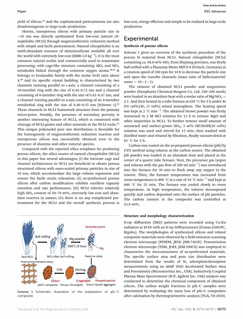
Scheme 1 Schematic illustration of the preparation of pSi–Ccomposite.
This journal is © The Royal Society of Chemistry 2015
low-cost, energy-efficient and simple to be realized in large-scaleproduction.
ExperimentalSynthesis of porous silicon
Scheme 1 gives an overview of the synthesis procedure of theporous Si material from NCLI. Natural clinoptilolite (NCLI)containing ca. 68.6 wt% SiO2 from Zhejiang province, was rstlyball-milled with a Planetary MonoMill P-6 (Fritsch, Germany) ata rotation speed of 500 rpm for 10 h to decrease the particle sizeand open the transfer channels (mass ratio of balls/material/water ¼ 10 : 2 : 1).
The mixture of obtained NCLI powder and magnesiumpowder (Sinopharm Chemical Reagent Co. Ltd, 100–200 mesh)were loaded in an alundum boat with amolar ratio of Mg/SiO2¼2.1. And then heated in a tube furnace at 650 �C for 4 h under Ar(95 vol%)/H2 (5 vol%) mixed atmosphere. The heating speedwas kept at 2 �C min�1. The obtained brown powder was rstlyimmersed in 2 M HCl solution for 12 h to remove MgO andother impurities in NCLI. To further remove small amount ofunreacted and surface-grown SiO2, 5 wt% HF/EtOH(10 vol%)solution was used and stirred for 15 min, then washed withdistilled water and ethanol by ltration, nally vacuum-dried at65 �C for 2 h.
Carbon was coated on the as-prepared porous silicon (pSi) byCVD method using toluene as the carbon source. The obtainedpSi powder was loaded in an alundum boat and placed at thecenter of a quartz tube furnace. Next, the precursor gas (argonand toluene with the gas ow of 200 ml min�1) was introducedinto the furnace for 30 min to ush away any oxygen in thereactor. Then, the furnace temperature was increased fromroom temperature to 800 �C at a rate of 10 �C min�1 and kept at800 �C for 25 min. The furnace was cooled slowly to roomtemperature. At high temperature, the toluene decomposedquickly and carbon deposited onto the surface of pSi particles.The carbon content in the composite was controlled at23.6 wt%.
Structure and morphology characterization
X-ray diffraction (XRD) patterns were recorded using Cu-Karadiation at 40 kV with an X-ray Diffractometer (D/max-2200/PC,Rigaku). The morphologies of synthesized silicon and relatedcomposite materials were observed by a eld emission scanningelectron microscope (FESEM, JEOL JSM-7401F). Transmissionelectron microscope (TEM, JOEL JEM-100CX) was employed tocharacterize the microstructures of as-synthesized materials.The specic surface area and pore size distribution weredetermined from the results of N2 adsorption/desorptionmeasurements using an ASAP 2020 Accelerated Surface Areaand Porosimetry (Micromeritics Inc., USA). Inductively CoupledPlasma Mass Spectrometer (ICP, Agilent Inc. USA) analysis wasconducted to determine the chemical component of obtainedsilicon. The carbon weight fractions in pSi–C samples weredetermined by evaluating the mass loss of pSi–C compositesaer calcination by thermogravimetric analysis (TGA, TA 2050).
RSC Adv., 2015, 5, 56772–56779 | 56773
RSC Advances Paper
View Article Online
Raman spectrums were obtained by using a Thermo ScienticDXR Raman microscope with a laser wavelength of 532 nm atroom temperature.
Cells assembling and electrochemical tests
The electrochemical performances of the as-prepared siliconwere tested using CR2016-type coin cells. The working elec-trodes were prepared by pasting a mixture of 60% active mate-rial, 20% Super P conductive carbon black (40 nm, Timical) and20% styrene butadiene rubber/sodium carboxymethyl cellulosebinder (SBR/SCMC, 3 : 5 by weight) onto pure Cu foil. Theelectrodes were cut to F12 mm sheets aer being dried rstly,and then further dried at 60 �C in vacuum for 4 h. The weight ofthe electrode material was weighed by using XS 105DU analyt-ical balances (METTLER TOLEDO, Inc.) and the readability is0.01 mg. The CR2016 coin cells were assembled in an argon-lled glove box (MB-10 compact, MBraun) with 1 M LiPF6/EC+ DMC (1 : 1 in volume ratio, ethylene carbonate (EC), dimethylcarbonate (DMC)) as electrolyte, including 10% uoroethylenecarbonate (FEC), ENTEK ET20-26 as separator, and pure lithiumfoil as counter electrode. The electrochemical performanceswere evaluated on a LAND battery test system (Wuhan KingnuoElectronics Co., Ltd., China) at 25 �C with the cut-off voltage of0.01 V versus Li/Li+ for discharge (Li insertion) and 1.2 V versusLi/Li+ for charge (Li extraction).
Result and discussion
Porous silicon material can be obtained directly from NCLI viamagnesiothermic reduction process as shown in Scheme 1. Themain impediments of magnesiothermic reduction process byusing NCLI as precursor are the occurrence of side reaction andagglomeration of obtained products due to the intricate cagestructure and small pore size distribution. During the magne-siothermic reaction, reducing agent Mg will become vapor stateat elevated temperature and react with SiO2 in NCLI, the relativereactions are as follows,23
SiO2 (s) + 2Mg (g) / Si (s) + 2MgO (s) (1)
If Mg is in excess, it will react with product Si. In addition,unreacted SiO2 could further react with MgO as followed:
Mg (g) + Si (s) / Mg2Si (2)
SiO2 (s) + 2MgO (s) / Mg2SiO4 (s) (3)
MgO, Mg2Si and unreacted Mg can be removed easily byhydrochloric acid etching, while side reaction product Mg2SiO4
is hard to be removed. It is crucial to prevent the formation ofthe inert and insulating Mg2SiO4 and obtain the desired siliconwith high quality.
NCLI is a natural micro- and mesoporous material withpolymodal pore size distribution. The microporosity (primaryporosity) is related to the clinoptilolite framework structure (asshown in Scheme 1), while the mesoporosity (secondaryporosity) is mainly caused by cleavage phenomenon of the NCLI
56774 | RSC Adv., 2015, 5, 56772–56779
grains.22 In view of this polymodal porosity, it is a suitablesilicon source for our work. However, pristine NCLI materialwithout ball-milling process provides relatively small transportchannels because of the close aggregation of thin-plates, whichmake it difficult for vapor Mg to penetrate into the inner part ofparticles uniformly. As a consequence, the side reaction withthe product of Mg2SiO4 could take place, and the distribution ofthe particles is poor (black appearance revealed in Fig. S1(a)†).The capacity of pSi obtained in this case drops quickly andvoltage polarization is serious (Fig. S2 and S3†). Aer high-energy mechanical milling (HEMM) pretreatment, the aggre-gating thin-plates are split off and the particle size decreasesfrom ca. 20–50 mm to ca. 2 mm as shown in Fig. 2, which isfavorable for the uniform penetration of Mg vapor into internalsilicon oxide with a siginicantly shorter diffusion path. As aresult, the side-reactions can be greatly suppressed and uniformSi powder with typical yellow appearance can be obtained(Fig. S1(b)†).
Apart from inhibiting side reaction, keeping a slow temper-ature ramp rate is very signicant to obtain silicon with goodperformance as well. This nding is in accordance with Cuiet al.16 In view of exothermic property of magnesiothermicreduction, local-heat accumulation may be incurred at hightemperature ramp rate, which may further trigger agglomera-tion of obtained silicon and block its inner space. Therefore,aer premixing with Mg powder, slow temperature ramp rate of2 �C min�1 is necessary to ensure that the heat from the reac-tion can be dissipated sufficiently.
Silicon-based aggregation containing silicon and inorganicspecies (e.g. unreacted SiO2, MgO and other mineral species)was obtained aer the magnesiothermic reduction process.Nano-scaled primary silicon particles can be formed from NCLIthin-plates, while silicon formed on sites of aggregated NCLIbars may go through further crystal growth into larger one orintergrowth into interconnected matrix. Aer being treated byHCl and HF solution to remove inorganic species, the porousstructure with nano-scaled primary particles is constructed byresidual silicon aggregation. At last a carbon layer was directlydeposited on the surface to improve the electronic conductivityand promote solid electrolyte interface (SEI) formation for long-term cycles.
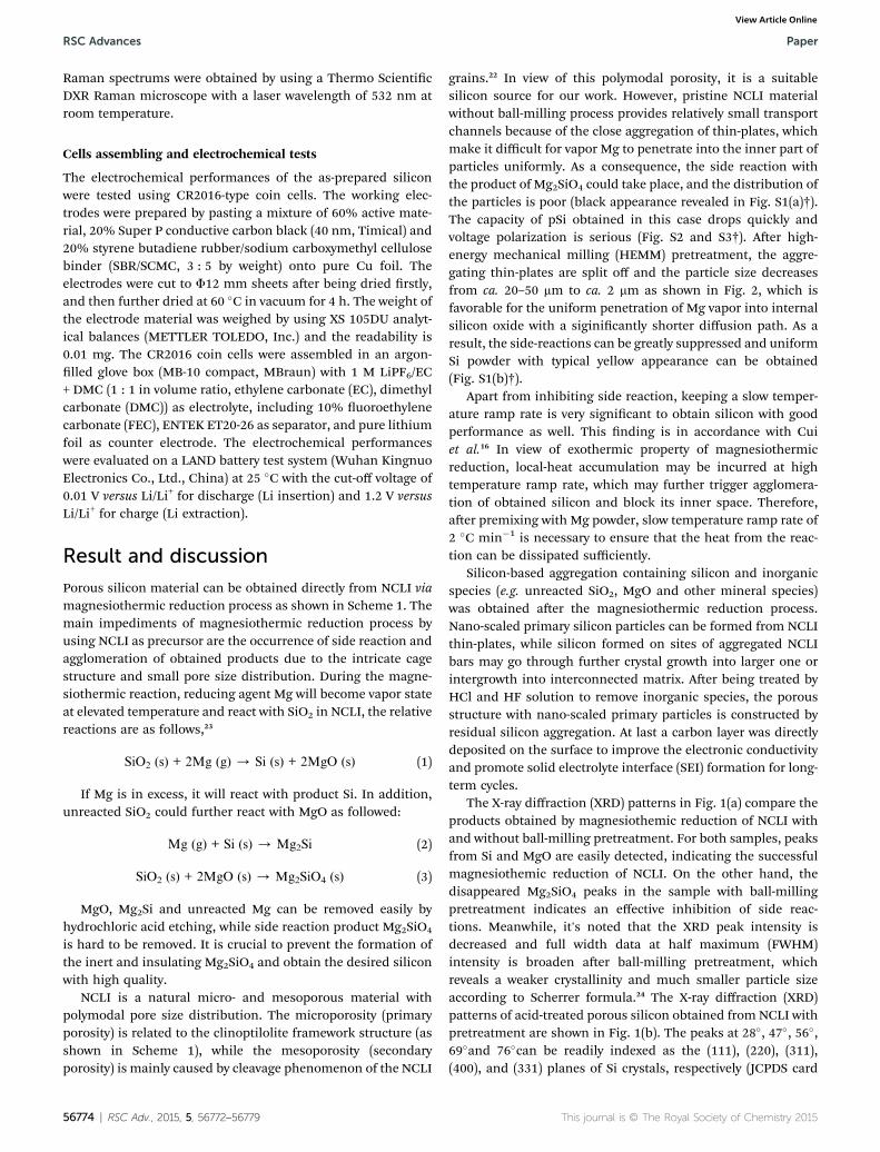
The X-ray diffraction (XRD) patterns in Fig. 1(a) compare theproducts obtained by magnesiothemic reduction of NCLI withand without ball-milling pretreatment. For both samples, peaksfrom Si and MgO are easily detected, indicating the successfulmagnesiothemic reduction of NCLI. On the other hand, thedisappeared Mg2SiO4 peaks in the sample with ball-millingpretreatment indicates an effective inhibition of side reac-tions. Meanwhile, it's noted that the XRD peak intensity isdecreased and full width data at half maximum (FWHM)intensity is broaden aer ball-milling pretreatment, whichreveals a weaker crystallinity and much smaller particle sizeaccording to Scherrer formula.24 The X-ray diffraction (XRD)patterns of acid-treated porous silicon obtained from NCLI withpretreatment are shown in Fig. 1(b). The peaks at 28�, 47�, 56�,69�and 76�can be readily indexed as the (111), (220), (311),(400), and (331) planes of Si crystals, respectively (JCPDS card
This journal is © The Royal Society of Chemistry 2015

Paper RSC Advances
View Article Online
27-1402), suggesting that the target product can be obtainedthrough choosing appropriate ratio of reactive materials inmagnesiothermic reduction reaction and impurities such asmagnesia, residual SiO2, magnesium and other mineral speciescan be removed by acid etching process. The Scherrer analysisbased on silicon patterns in Fig. 1(b) reveals a crystallite size of12.3 nm, which is consistent with an estimate from TEM.Moreover, because silicon is directly formed from NCLI, thepurity is a subject which can't be ignored. According to ICPresult, the main impurity in obtained Si is determined to be Al(�3 wt%), which comes from the cage structure of NCLI. Otherimpurities (K, Na, Fe, Ca and Mg) are common to mineralsubstance and their total concentration is less than 1%. Itappears that these impurities do not exert an obvious negativeeffect.
SEM and TEM characterizations are used to investigate themorphology and structure of the samples. Fig. 2 showsmorphologies of NCLI with/without ball-milling pretreatmentand the obtained silicon samples. It can be seen from Fig. 2(a)that pristine NCLI contains particles with a very broad sizedistribution from less than 5 mm to �50 mm. From Fig. 2(b) wecan see the lamellar texture of NCLI with overlapping plates orbars. The thin-plates are of 30–50 nm in thickness and 700–800nm in length. Furthermore, the transport channels of NCLI(represented as mesopores) caused by splitting of these face-to-face arranging thin plates can be found obviously. However, thesize of these mesopores is relatively small due to the closeaggregation of planes or bars. Aer ball-milling, the particles ofNCLI were broken down to smaller ones with a homogeneousparticle distribution around 2 mm in size (Fig. 2(c)). Moreover,the cleavage degrees are aggrandized signicantly as a result ofmechanical powdering process and transport channels are
Fig. 1 XRD patterns of (a) products obtained by magnesiothermicreduction from NCLI with and without ball-milling pretreatment(before acid etching); (b) acid-treated porous silicon obtained fromNCLI with pretreatment.
This journal is © The Royal Society of Chemistry 2015
opened up (as shown in Fig. 2(d)), which is in favour of theuniform penetration of vapour Mg. As shown in Fig. 2(e) and (f),the sponge-like silicon composed of highly porous network ofinterconnected crystalline silicon is nally obtained aer mag-nesiothemic reduction and acid etching.
The porous properties of NCLI with ball-milling treatmentand the obtained pSi are further examined by Brunauer–Emmett–Teller (BET) measurement (Fig. 3). As exhibited byFig. 3(a), polymodel pores around 4 nm and 17 nm areobservable for NCLI with ball-milling. The broad pore sizedistribution (inset in Fig. 3(a)) may be associated with thedifferent cleavage degree between thin plates in NCLI grains.The nitrogen adsorption–desorption result shown in Fig. 3(b)indicates the presence of pores in the obtained Si. Specicsurface area of the pSi is 148.04 m2 g�1, which is much higherthan that of the as-received NCLI (29.5 m2 g�1) and NCLI aerball-milling (32.1 m2 g�1). And the curves at a relative pressureof 0.7–0.9 can be classied as a type IV isotherm characteristicof mesoporous materials.25 Furthermore, the BJH pore diameterdistribution (inset in Fig. 3(b)) reveals that the main poredistribution lies in �10 nm, with a cumulative pore volume of0.692 cm g�1. The pores arise partly from the nature NCLIstructure and partly from Al and MgO completely removed viachemical etching. Aer carbon coating, the main pore distri-bution decreases from �10 nm to �8 nm due to the carbondeposition within the nano-pores via the penetration of toluenemolecules, as determined by BJH pore diameter distribution inFig. S4.† The broad range of pore size is attributable to therandom pore distribution in NCLI. They could effectively
Fig. 2 SEM images of (a and b) NCLI precursor; (c and d) NCLI afterball-milling; (e and f) as-synthesized silicon after acid etching.
RSC Adv., 2015, 5, 56772–56779 | 56775

Fig. 4 (a)TEM image of pSi; (b) highlighted image of the selected areasin (a) and inset is HR-TEM image of obtained silicon; (c) EDS spectrumcaptured for the region shown in (a); (d) TEM image of pSi–Ccomposite.
RSC Advances Paper
View Article Online
accommodate the volume changes of silicon during charge anddischarge.
The porous structure of as-prepared silicon can be furtherobserved by TEM images in Fig. 4. As shown in Fig. 4(a),nanopores with a broad range of 3–20 nm are formed. Theenlarged image of selected area in Fig. 4(a) conrms that thenanoporous structure is formed by primary silicon crystalliteswith uniform size distribution of �10 nm, which is in goodagreement with the crystalline size based on the Scherreranalysis of Fig. 1(b). The high internal porosity and small size ofprimary silicon particle can better accommodate the volumechange of Si and improve its stability. The lattice fringes withthe interplanar spacing of 3.1 A correspond to Si (111) plane(inset in Fig. 4(b)), which further prove that the silicon wassuccessfully obtained from NCLI. EDS spectrum analysis(Fig. 4(c)) demonstrated the presence of Al, which is in agree-ment with the results of ICP. Because Al exists in the framestructure of NCLI, it may be imbedded in synthesized Si so thatHCl can't access it during etching, which nally results in traceamount of residual Al.
Based on the poor-conducting property of silicon, a surfacemodication method of CVD was employed to further enhancethe electrochemical behavior of pSi. Toluene was used ascarbon source to acquire the carbon coated nanoporous siliconcomposite (pSi–C) with the carbon content of 23.6 wt%. Theresultant pSi–C composite was investigated by Raman spec-troscopy. The two peaks at 508 cm�1 and 840 cm�1 in Fig. 5(a)are associated with crystalline Si. The other two additionalpeaks at 1333 cm�1 and 1589 cm�1 are attributed to the D(disordered) and G (graphite) band of carbon, respectively,indicating the presence of carbon. The ratio of D band to G
Fig. 3 Nitrogen adsorption–desorption isotherm linear plot of (a)NCLI-after ball-milling; (b) obtained porous silicon and the insets areBarrett–Joyner–Halenda (BJH) pore size distribution.
56776 | RSC Adv., 2015, 5, 56772–56779
band is estimated to be �0.92, demonstrating a relatively lowgraphitization degree for the pSi–C composite. Fig. 5(b) pres-ents the morphology of pSi–C composite. The particles becamelarger as a result of carbon deposition compared with theprimary silicon crystallites with the size of �10 nm. The carbonlayer can be further studied through TEM and a fairly homo-geneous carbon layer with a thickness of ca. 5 nm is stronglybound to the surface of the pSi–C composite (Fig. 4(d)). We canalso see the lattice fringes clearly with interplanar spacing of3.1 A, corresponding to Si (111) plane.
Fig. 6 shows the voltage proles of the pSi and pSi–Ccomposite cycled between 0.01 and 1.2 V at 0.05C for the rsttwo cycles and 0.2C for the following cycles. The rst discharge(lithiation) curve displays a long at plateau below 0.1 V, whichcorresponds to the Li-alloying process of crystalline Si to formamorphous LixSi phase.26 Aerwards, the discharge and chargecurves show the characteristic of amorphous Si. pSi electrodedelivers the rst charge and discharge capacities of ca.1768.5 mA h g�1 and ca. 2884.4 mA h g�1 respectively (shown inFig. 6(a)), corresponding to its columbic efficiency of 61.3%. Therelatively low columbic efficiency may be attributed to mass
Fig. 5 (a) Raman spectrum of pSi–C composite; (b) SEM images ofpSi–C composite.
This journal is © The Royal Society of Chemistry 2015

Paper RSC Advances
View Article Online
defected points and abundant surface area of pSi, whichconsumedmore charges to form the solid electrolyte interphase(SEI) layer during the rst discharge process. During cycling, thevoltage polarization of pSi becomes apparent and its speciccapacity drops gradually. To enhance the electric conductivity ofsilicon and stabilize the whole structure, carbon layer wascoated on the surface of pSi. As shown in Fig. 6(b), the rstcharge and discharge capacities of pSi–C composite electrodeare ca. 1302.5 mA h g�1 and ca. 1835.7 mA h g�1 respectively,corresponding to its columbic efficiency of 70.9%. The speciccharge–discharge capacities were calculated according to thewhole weight of silicon and carbon for pSi–C composite elec-trode. Aer carbon coating, some nanopores in pSi will be lledwith carbon and the surface area was decreased, which mayassociate with the slight improvement of columbic efficiency forpSi–C composite electrode. In addition, the reproducible shapeof curves for pSi–C composite electrode aer the initial Liintercalation and de-intercalation process indicates the highelectrochemical reversibility.
To further characterize the electrochemical properties ofpSi–C composite electrodes, cyclic voltammetry (CV) wasmeasured at a scan rate of 0.1 mV s�1 over the potential windowof 0–1.5 V versus Li/Li+(shown in Fig. 7). In the rst cathodicscan, a broad peak at 1.26 V is ascribed to the formation of a SEIlayer at the pSi–C/electrolyte interface, which disappears fromthe subsequent cycles. The distinct current peak below 0.13 Vcorresponds to Li insertion into crystalline Si to form amor-phous LixSi phase.27,28 A new cathodic peak at �0.2 V appearsfrom the second cycle, which could be related to alloying
Fig. 6 Charge–discharge curves of the (a) pSi and (b) pSi–Ccomposite for the 1st, 2nd, 20th and 50th cycles at 0.05C for the initialtwo cycles and at 0.2C for the following cycles (the specific charge–discharge capacities were calculated according to the whole weight ofsilicon and carbon for pSi–C composite electrode).
This journal is © The Royal Society of Chemistry 2015
reaction in the activated electrode with amorphous Si phase. Inthe anodic scan, the two peaks at 0.32 V and 0.47 V are observedin the rst cycle and become more distinct in the followingones. These two peaks correspond to delithiation of amorphousLixSi to a-Si.29 Notably, aer six CV cycles, the proles becamealmost overlapped, which further veries the good cyclingstability of pSi–C electrode.
Fig. 8(a) compares the reversible capacity and stability for thepSi obtained from NCLI, pSi–C composite and commercialnano-silicon (50–200 nm). Although the nano-Si electrodeexhibits the highest initial capacity near 2300 mA h g�1, a rapidcapacity fade occurs from the very start cycling due to theparticle pulverization and electric disconnection of the mate-rial. The pSi electrode presents the initial capacity of ca.1768.5 mA h g�1 and its capacity retention at the 200th cycle is�65.4% against at the 3rd cycle. In contrast, pSi–C compositedelivers superior electrochemical reversibility and its capacity of87.5% can be retained under the same condition. The typicalcoulombic efficiency of pSi–C composite approaches 99.4%. Itsgood cycling stability can be ascribed to the rich porous struc-ture, nano-scaled primary particle size and conducting net-workformed by carbon layer, which buffer the huge volume changeof silicon effectively and improve the mechanical integrity andconductivity of composite material. Meanwhile, this pSi–Ccomposite electrode shows excellent rate performance. Fig. 8(b)shows that the capacity reposefully declines from ca. 1457.7 toca. 907.7 mA h g�1 as the C-rate increased in stages from 0.05Cto 2C. When the C-rate turns back to 0.05C, the capacity canrecover to ca. 1432.7 mA h g�1. However, the capacity of the pSielectrode drastically declines from ca. 1854.1 mA h g�1 to ca.672.9 mA h g�1 with 63.7% capacity loss under the sameconditions.
The electrochemical impedance spectroscopy (EIS) of the pSiand pSi–C composite electrode was investigated to gain furtherinsights into the improved cycling performance (Fig. 9). Thedepressed semicircle in the high-middle frequency region isassigned to the overlap between the SEI lm and the interfacial
Fig. 7 Cyclic voltammograms of the pSi–C composite electrodemeasured in the voltage region of 0–1.5 V with a scan rate of0.1 mV s�1.
RSC Adv., 2015, 5, 56772–56779 | 56777

Fig. 8 (a) Cycling performance of pSi, pSi–C composite andcommercial nano-silicon electrodes at 0.05C for the initial two cyclesand at 0.2C for the following cycles; (b) reversible capacities of pSi andpSi–C composite electrodes cycled at different C-rates from 0.05C to2C (the specific charge–discharge capacities were calculatedaccording to the whole weight of silicon and carbon for pSi–Ccomposite electrode).
RSC Advances Paper
View Article Online
charge transfer impedance, while the oblique straight line inthe low frequency region corresponds to the ion diffusionwithin the anodes. The Nyquist plots of the two electrodesreveals that the total SEI and charge transfer resistancesdecrease from the rst cycle to the 60th cycle, which may beattributed to the enhanced electronic conductivity due to trap-ped lithium in the electrode.30 Moreover, the pSi–C compositeelectrode exhibits apparent smaller high frequency semicircleand become basically stable aer 60 cycles, indicating that
Fig. 9 Impedance plots for the pSi and pSi–C composite electrode at1.2 V vs. Li/Li+ after different cycles.
56778 | RSC Adv., 2015, 5, 56772–56779
pSi–C composite is more favorable for establishing a stableelectronic and ionic transport pathways at the electrode–elec-trolyte interface. The EIS results can explain why pSi–Ccomposite electrode possesses better capacity retention andrate performance than pSi electrode.
Conclusions
In summary, nanoporous silicon material with a sponge-likemorphology was successfully prepared from low-cost earth-abundant natural clinoptilolite (NCLI). The polyporous natureof NCLI is benecial to its reduction to silicon with porousstructure. The nanopores serve as buffer zone to effectivelyaccommodate the volume variations of silicon during lithiationand the well-dispersed primary particles in size of �10 nmensure the facile strain relaxation. Aer surface carbon coating,the pSi–C composite displays a superior stable capacity of ca.1257 mA h g�1 and good stability with 87.5% capacity retentionon the 200th cycle versus the 3rd one (compared at the samecurrent rate). The improvements can be ascribed to the nano-pores, very small primary particle size in �10 nm and highlyconductive carbon layer. The simple and facile synthesis tech-nique, low cost silica precursor and excellent electrochemicalperformance make this Si composite a promising candidate forlarge-scale production of the next-generation high capacitylithium-ion battery anode material.
Acknowledgements
This work was supported by National Key 973 Program of thePRC (no. 2014CB932303) and SJTU-UM Joint Research Project.
Notes and references
1 H. Wu and Y. Cui, Nano Today, 2012, 7, 414–429.2 H. K. Liu, Z. Guo, J. Wang and K. Konstantinov, J. Mater.Chem., 2010, 20, 10055–10057.
3 Y. G. Guo, J. S. Hu and L. J. Wan, Adv. Mater., 2008, 20, 2878–2887.
4 J. Cho, J. Mater. Chem., 2010, 20, 4009–4014.5 N. Liu, Z. Lu, J. Zhao, M. T. McDowell, H.-W. Lee, W. Zhaoand Y. Cui, Nat. Nanotechnol., 2014, 9, 187–192.
6 S.-H. Ng, J. Wang, D. Wexler, K. Konstantinov, Z.-P. Guo andH.-K. Liu, Angew. Chem., Int. Ed., 2006, 45, 6896–6899.
7 Y. Zhao, X. Liu, H. Li, T. Zhai and H. Zhou, Chem. Commun.,2012, 48, 5079–5081.
8 R. C. de Guzman, J. Yang, M. M.-C. Cheng, S. O. Salley andK. Y. Simon Ng, J. Power Sources, 2014, 246, 335–345.
9 H. Jia, P. Gao, J. Yang, J. Wang, Y. Nuli and Z. Yang, Adv.Energy Mater., 2011, 1, 1036–1039.
10 P. Gao, H. Jia, J. Yang, Y. Nuli, J. Wang and J. Chen, Phys.Chem. Chem. Phys., 2011, 13, 20108–20111.
11 M. Ge, Y. Lu, P. Ercius, J. Rong, X. Fang, M. Mecklenburg andC. Zhou, Nano Lett., 2014, 14, 261–268.
12 W. Wang, Z. Favors, R. Ionescu, R. Ye, H. H. Bay, M. Ozkanand C. S. Ozkan, Sci. Rep., 2015, 5, 1–5.
13 Q. Li, L. Yin and X. Gao, RSC Adv., 2015, 5, 35598–35607.
This journal is © The Royal Society of Chemistry 2015

Paper RSC Advances
View Article Online
14 L. Shen, X. Guo, X. Fang, Z. Wang and L. Chen, J. PowerSources, 2012, 213, 229–232.
15 N. Hai, I. Grigoriants and A. Gedanken, J. Phys. Chem. C,2009, 113, 10521–10526.
16 N. Liu, K. Huo, M. T. McDowell, J. Zhao and Y. Cui, Sci. Rep.,2013, 3, 1–7.
17 Z. Favors, W. Wang, H. H. Bay, Z. Mutlu, K. Ahmed, C. Liu,M. Ozkan and C. S. Ozkan, Sci. Rep., 2014, 4, 1–7.
18 K. Pavelic, M. Hadzija, L. Bedrica, J. Pavelic, I. Đikic,M. Katic, M. Kralj, M. H. Bosnar, S. Kapitanovic andM. Poljak-Blazi, J. Mol. Med., 2001, 78, 708–720.
19 Y. F. Wang, F. Lin and W. Q. Pang, J. Hazard. Mater., 2007,142, 160–164.
20 Y. F. Tao, Y. Qiu, S. Y. Fang, Z. Y. Liu, Y. Wang and J. H. Zhu,J. Hazard. Mater., 2010, 180, 282–288.
21 M. W. Ackley, R. F. Giese and R. T. Yang, Zeolites, 1992, 12,780–788.
22 M. Sprynskyy, R. Golembiewski, G. Trykowski andB. Buszewski, J. Phys. Chem. Solids, 2010, 71, 1269–1277.
This journal is © The Royal Society of Chemistry 2015
23 W. Chen, Z. Fan, A. Dhanabalan, C. Chen and C. Wang, J.Electrochem. Soc., 2011, 158, A1055–A1059.
24 H. Borchert, E. V. Shevchenko, A. Robert, I. Mekis,A. Kornowski, G. Grubel and H. Weller, Langmuir, 2005, 21,1931–1936.
25 S. Brunauer, L. S. Deming, W. E. Deming and E. Teller, J. Am.Chem. Soc., 1940, 62, 1723–1732.
26 C. K. Chan, H. Peng, G. Liu, K. McIlwrath, X. F. Zhang,R. A. Huggins and Y. Cui, Nat. Nanotechnol., 2008, 3, 31–35.
27 M. Obrovac and L. Krause, J. Electrochem. Soc., 2007, 154,A103–A108.
28 X. Feng, J. Yang, P. Gao, J. Wang and Y. Nuli, RSC Adv., 2012,2, 5701–5706.
29 L. Zhang, W. Hao, H. Wang, L. Zhang, X. Feng, Y. Zhang,W. Chen, H. Pang and H. Zheng, J. Mater. Chem. A, 2013,1, 7601–7611.
30 X. Chen, K. Gerasopoulos, J. Guo, A. Brown, C. Wang,R. Ghodssi and J. N. Culver, Adv. Funct. Mater., 2011, 21,380–387.
RSC Adv., 2015, 5, 56772–56779 | 56779