
Nano Energy - Northeastern University · Nano Energy journal homepage ... Hamish A. Millera,⁎,...
13
Contents lists available at ScienceDirect Nano Energy journal homepage: www.elsevier.com/locate/nanoen Full paper Highly active nanostructured palladium-ceria electrocatalysts for the hydrogen oxidation reaction in alkaline medium Hamish A. Miller a, ⁎ , Francesco Vizza a, ⁎ , Marcello Marelli b , Anicet Zadick c,d , Laetitia Dubau c,d , Marian Chatenet c,d,e , Simon Geiger f , Serhiy Cherevko f,g , Huong Doan h , Ryan K. Pavlicek h , Sanjeev Mukerjee h , Dario R. Dekel i,j, ⁎ a Istituto di Chimica dei Composti Organometallici (CNR-ICCOM), via Madonna del Piano 10, 50019 Sesto Fiorentino, Firenze, Italy b Istituto di Scienze e Tecnologie Molecolari (ISTM-CNR), via Camillo Golgi 19, 20133 Milano, Italy c University of Grenoble Alpes, LEPMI, F-38000 Grenoble, France d CNRS, LEPMI, F-38000 Grenoble, France e French University Institute (IUF), Paris, France f Department of Interface Chemistry and Surface Engineering, Max-Planck-Institut für Eisenforschung GmbH, 40237 Düsseldorf, Germany g Helmholtz-Institute Erlangen-Nürnberg for Renewable Energy (IEK-11), Forschungszentrum Jülich, 91058 Erlangen, Germany h Department of Chemistry and Chemical Biology, Northeastern University, Boston, MA, 02115, USA i The Wolfson Department of Chemical Engineering, Technion – Israel Institute of Technology, Haifa 3200003, Israel j The Nancy & Stephan Grand Technion Energy Program (GTEP), Technion – Israel Institute of Technology, Haifa 3200003, Israel ARTICLE INFO Keywords: Fuel cell Platinum free Anion exchange membrane Palladium Ceria, hydrogen oxidation ABSTRACT We report an interesting new class of bifunctional electrocatalysts, Pd/C-CeO 2 , with excellent activity and stability for the hydrogen oxidation reaction (HOR) under alkaline conditions. The unique structure of palladium deposited onto a mixed support of Vulcan XC-72 carbon and CeO 2 consists of Pd metal preferable deposited on the ceria regions of the catalyst. The CeO 2 -Pd interaction leads to enhanced HOR kinetics and increased stability. Here we compare catalysts with three different Pd loadings and show that the 10 wt% Pd sample has optimized activity. Hydrogen pumping and fuel cell experiments based on this catalyst show higher activities as compared to a Pd/C sample without ceria. Metal dissolution tests and identical location transmission microscopy experiments show that the catalyst stability under harsh potential cycling experiments in alkaline medium is significantly improved as compared to Pd/C, making this material one of the best options for use as highly active and highly stable electrocatalysts for the HOR in anion exchange membrane fuel cells. 1. Introduction Anion exchange membrane fuel cells (AEM-FCs) have received increasing attention as this technology has the potential to replace expensive platinum and platinum alloy materials currently used in fuel cell electrodes, significantly reducing the cost of fuel cell devices [1]. Recently, significant progress has been made in improving material components for AEM-FCs in particular cell hardware, membranes, ionomers and cathode catalysts for the oxygen reduction reaction (ORR) [2–16]. However, the sluggish hydrogen oxidation reaction (HOR) kinetics of electrocatalysts under alkaline conditions have limited the development of affordable Pt-free catalysts and AEM-FC technology is still awaiting new advanced catalytic materials to fulfill its potential [17]. Hence, the realization of a completely Pt-free AEM-FC requires the development of novel anode catalyst structures that enhance the HOR of the supported metal nanoparticles (NPs) [18].A new class of Pd based materials that exploit mixed carbon and metal oxide supports has recently been reported that have led for the first time, to performances of non-Pt AEM-FCs with power densities around 0.5 W cm -2 , operating with partially filtered air at the cathode and dry hydrogen at the anode [19]. In particular, the addition of CeO 2 to Vulcan XC-72 carbon with a 50:50 weight ratio yields a conductive support onto which Pd deposits preferentially onto the ceria regions (confirmed by EDX-STEM and XAS investigations) [19]. When com- pared to a Pd supported on carbon catalyst (without ceria) with the same particle size distribution and metal loading, a 5-fold improve- ment is obtained in the anode performance under the same fuel cell conditions for the Pd/C-CeO 2 catalyst. It is believed that the presence of an intimate contact between ceria and Pd enhances the OH - transfer from the anion conducting membrane and ionomer regions of the fuel http://dx.doi.org/10.1016/j.nanoen.2017.01.051 Received 25 November 2016; Received in revised form 18 January 2017; Accepted 24 January 2017 ⁎ Corresponding authors. E-mail address: [email protected] (H.A. Miller). Nano Energy 33 (2017) 293–305 Available online 26 January 2017 2211-2855/ © 2017 Elsevier Ltd. All rights reserved. MARK
-
Upload
truongdieu -
Category
Documents
-
view
214 -
download
0
Transcript of Nano Energy - Northeastern University · Nano Energy journal homepage ... Hamish A. Millera,⁎,...

Contents lists available at ScienceDirect
Nano Energy
journal homepage: www.elsevier.com/locate/nanoen
Full paper
Highly active nanostructured palladium-ceria electrocatalysts for thehydrogen oxidation reaction in alkaline medium
Hamish A. Millera,⁎, Francesco Vizzaa,⁎, Marcello Marellib, Anicet Zadickc,d, Laetitia Dubauc,d,Marian Chatenetc,d,e, Simon Geigerf, Serhiy Cherevkof,g, Huong Doanh, Ryan K. Pavlicekh,Sanjeev Mukerjeeh, Dario R. Dekeli,j,⁎
a Istituto di Chimica dei Composti Organometallici (CNR-ICCOM), via Madonna del Piano 10, 50019 Sesto Fiorentino, Firenze, Italyb Istituto di Scienze e Tecnologie Molecolari (ISTM-CNR), via Camillo Golgi 19, 20133 Milano, Italyc University of Grenoble Alpes, LEPMI, F-38000 Grenoble, Franced CNRS, LEPMI, F-38000 Grenoble, Francee French University Institute (IUF), Paris, Francef Department of Interface Chemistry and Surface Engineering, Max-Planck-Institut für Eisenforschung GmbH, 40237 Düsseldorf, Germanyg Helmholtz-Institute Erlangen-Nürnberg for Renewable Energy (IEK-11), Forschungszentrum Jülich, 91058 Erlangen, Germanyh Department of Chemistry and Chemical Biology, Northeastern University, Boston, MA, 02115, USAi The Wolfson Department of Chemical Engineering, Technion – Israel Institute of Technology, Haifa 3200003, Israelj The Nancy & Stephan Grand Technion Energy Program (GTEP), Technion – Israel Institute of Technology, Haifa 3200003, Israel
A R T I C L E I N F O
Keywords:Fuel cellPlatinum freeAnion exchange membranePalladiumCeria, hydrogen oxidation
A B S T R A C T
We report an interesting new class of bifunctional electrocatalysts, Pd/C-CeO2, with excellent activity andstability for the hydrogen oxidation reaction (HOR) under alkaline conditions. The unique structure ofpalladium deposited onto a mixed support of Vulcan XC-72 carbon and CeO2 consists of Pd metal preferabledeposited on the ceria regions of the catalyst. The CeO2-Pd interaction leads to enhanced HOR kinetics andincreased stability. Here we compare catalysts with three different Pd loadings and show that the 10 wt% Pdsample has optimized activity. Hydrogen pumping and fuel cell experiments based on this catalyst show higheractivities as compared to a Pd/C sample without ceria. Metal dissolution tests and identical locationtransmission microscopy experiments show that the catalyst stability under harsh potential cycling experimentsin alkaline medium is significantly improved as compared to Pd/C, making this material one of the best optionsfor use as highly active and highly stable electrocatalysts for the HOR in anion exchange membrane fuel cells.
1. Introduction
Anion exchange membrane fuel cells (AEM-FCs) have receivedincreasing attention as this technology has the potential to replaceexpensive platinum and platinum alloy materials currently used in fuelcell electrodes, significantly reducing the cost of fuel cell devices [1].Recently, significant progress has been made in improving materialcomponents for AEM-FCs in particular cell hardware, membranes,ionomers and cathode catalysts for the oxygen reduction reaction(ORR) [2–16]. However, the sluggish hydrogen oxidation reaction(HOR) kinetics of electrocatalysts under alkaline conditions havelimited the development of affordable Pt-free catalysts and AEM-FCtechnology is still awaiting new advanced catalytic materials to fulfill itspotential [17]. Hence, the realization of a completely Pt-free AEM-FCrequires the development of novel anode catalyst structures that
enhance the HOR of the supported metal nanoparticles (NPs) [18]. Anew class of Pd based materials that exploit mixed carbon and metaloxide supports has recently been reported that have led for the firsttime, to performances of non-Pt AEM-FCs with power densities around0.5 W cm−2, operating with partially filtered air at the cathode and dryhydrogen at the anode [19]. In particular, the addition of CeO2 toVulcan XC-72 carbon with a 50:50 weight ratio yields a conductivesupport onto which Pd deposits preferentially onto the ceria regions(confirmed by EDX-STEM and XAS investigations) [19]. When com-pared to a Pd supported on carbon catalyst (without ceria) with thesame particle size distribution and metal loading, a 5-fold improve-ment is obtained in the anode performance under the same fuel cellconditions for the Pd/C-CeO2 catalyst. It is believed that the presenceof an intimate contact between ceria and Pd enhances the OH- transferfrom the anion conducting membrane and ionomer regions of the fuel
http://dx.doi.org/10.1016/j.nanoen.2017.01.051Received 25 November 2016; Received in revised form 18 January 2017; Accepted 24 January 2017
⁎ Corresponding authors.E-mail address: [email protected] (H.A. Miller).
Nano Energy 33 (2017) 293–305
Available online 26 January 20172211-2855/ © 2017 Elsevier Ltd. All rights reserved.
MARK
cell to the metal surface where the HOR takes place [20]. Cyclicvoltammetry (CV) studies have shown a weakening of the Pd-Hbonding when ceria is in contact with Pd [19]. The oxidative desorptionof hydrogen from Pd (Eq. (1)) is considered to be the rate determiningstep (rds) of the HOR under alkaline conditions (Eq. (1)) [21,22].
Pd H OH Pd H O e− + → + +−2
− (1)
Hence, a weakening of the bonding of the adsorbed hydrogen canenhance significantly the kinetics. Due to the increasing complexity andchallenge of the mechanism of HOR in alkaline media as compared toHOR in acidic medium, the stability of the catalyst is of concern. Due tothe scarce data available on HOR catalysts in alkaline medium, stabilitytests of these materials have not been reported. Specifically for Pdbased catalysts, while Pd dissolution in acidic media is well documen-ted [23,24], literature data on Pd corrosion in alkaline media is veryscarce. Also Pourbaix diagrams, showing stability windows for differentspecies in the E vs. pH space, do not give any conclusive answer towhether Pd corrodes in base. According to a previous report, Pd shouldbe extremely stable in typically used alkaline electrolytes [25]. In thatreport, the authors could not detect any signs of Pd dissolution in 0.5 MKOH at 25 °C. However, at alkali concentrations of 6 M KOH or higher,and at elevated temperatures some dissolution was detected. Bolzan,interpreting the results obtained using rotating ring disk electrodetests, suggested that some Pd dissolution exists in 1 M NaOH, butstressed that the dissolution rates/amounts are significantly lower thanthat measured in acidic electrolytes [26]. More recently, however, usingidentical-location transmission electron microscopy (ILTEM) coupledto electrochemistry, Zadick et al. demonstrated that the relativestability of Pd towards electrochemical dissolution in base was not awarranty for the stability of state-of-the-art carbon supported Pdnanoparticles at high pH. Indeed, the particles suffer dramatic detach-ment from their carbon support, overall yielding a very large decreaseof electrochemical surface area (ECSA) in a rather limited number ofvoltammetric cycles (typically below 1000 cycles at 100 mV s−1 in therange 0.1 < E < 1.23 V vs RHE) in 0.1 M NaOH at 25 °C [27].Surprisingly, Pt/C nanoparticles were demonstrated to suffer evenmore such degradation in base electrolytes [28].
In the present study, we report our continued investigation of theproperties of the Pd/C-CeO2 catalyst, showing its enhanced HORactivity in a hydrogen-pumping cell, confirming the ceria effect onthe catalytic activity of the Pd. We also report further details on itsproperties by comparing different Pd ratios on the same C-CeO2
support (6 wt%, 10 wt% and 20 wt% Pd). Finally, several stabilitystudies of the Pd-C-CeO2 catalyst are also reported here for the firsttime, using both in situ inductively coupled plasma mass spectrometry(ICP-MS) and identical-location transmission electron microscopyexperiments, as well as using hydrogen-pumping cells.
2. Experimental
All material manipulations during materials preparation, except asstated otherwise, were routinely performed under nitrogen atmosphereusing standard airless technique. Carbon black (Vulcan XC-72 pellets)was purchased from Cabot Corp., USA. All metal salts and reagentswere purchased from Aldrich and used as received. All the solutionswere freshly prepared with doubly distilled deionized water.
2.1. Material syntheses
2.1.1. Synthesis of Pd/C (10 wt%)Vulcan XC-72 (6.0 g) was suspended in 250 mL of ethylene glycol
and sonicated for 20 min in a 500 mL three-neck round-bottomedflask. Then a solution of 1.0 g of PdCl2 in a mixture of H2O (50 mL),ethylene glycol (50 mL) and 6 mL HCl (37%) was added dropwiseunder stirring in a N2 stream. After adequate stirring, an alkalinesolution of NaOH (5 g) in H2O (10 mL) and ethylene glycol (35 mL)
was introduced in the reactor which then was heated at 125 °C for 3 hagain under a N2 atmosphere. Then the mixture was cooled to roomtemperature. The solid product was filtered off and washed with H2O toneutral pH. The final product was dried in vacuum oven at 40 °C.(Yield: 6.53 g).
2.1.2. Synthesis of C-CeO2 support (50:50)Vulcan XC-72 (4 g) was added to a solution of Ce(NO3)3·6H2O
(10.1 g) in H2O (250 mL). The mixture was kept under stirring for60 min and sonicated for 30 min. After adjusting the pH to 12 withKOH, the resulting suspension was stirred for 2 h. The product wasseparated by filtration and washed with H2O until neutral pH wasobtained. The product was dried at 65 °C, then subsequently heatedunder air in a tube furnace at 250 °C for 2 h. Cooling to roomtemperature was undertaken under a flow of Ar. The yield of C-CeO2
was 7.15 g.
2.1.3. Synthesis of Pd/C-CeO2
The synthetic procedure used was the same for each catalyst withthe only difference the amount of Pd salt used to obtain the desiredloading of 6 wt%Pd, 10 wt%Pd and 20 wt%Pd. As an example for the10 wt%Pd catalyst, the synthesis was as follows: C-CeO2 (4 g) wassuspended in water (500 mL), stirred vigorously for 30 min andsonicated for 20 min. To this mixture, a solution of K2PdCl4 (1.38 g)in water (60 mL) was slowly added (during ca. 1 h) under vigorousstirring, followed by addition of an aqueous solution of 2.5 M KOH(8.4 mL). Next, ethanol (50 mL) was added and the resulting mixturewas heated at 80 °C for 60 min. The desired product Pd/C-CeO2 wasfiltered off, washed several times with distilled water to neutrality andfinally dried under vacuum at 65 °C until constant weigh was reached.The yield of Pd/C-CeO2 was 4.45 g.
2.2. Electrochemical and physical characterization
Transmission electron microscopy (TEM) was performed on aPhilips CM12 microscope at an accelerating voltage of 100 kV. Themicroscope was equipped with an EDAX energy dispersive microana-lysis system. Scanning Electron Microscopy (SEM) was performed on aHITACHI S4800 microscope operating at 15 kV. High resolution TEM(HR-TEM) images were recorded with a Zeiss Libra 200 FE TEMequipped with a double tilt goniometer at 200 kV and FEI Tecnai-F30microscope which was operated at 300 kV. The active metal surfacearea was determined by CO chemisorption method, adapted to carbonsupported materials, at 70 °C by the use of an ASAP 2020 C Instrument(Micromeritics Corp.). Before the measurements, the samples werereduced at 210 °C with H2 and treated in vacuum at the sametemperature for 15 h.
Cyclic Voltammetry (CV) measurements were performed with aPrinceton 2273 A potentiostat/galvanostat, using a three-electrodearrangement with an Ag/AgCl reference electrode and a platinum foil(25 mm×25 mm×0.1 mm) as counter electrode. No IR drop compen-sation was applied to any of the performed experiments. The potentialscale of the CV curves was then converted to the reversible hydrogenelectrode (RHE) scale.
Procedures for cell preparation for fuel cell tests are describedelsewhere [19]. Membrane electrode assemblies (MEAs) (5 cm2 activearea) consisting of Ag alloy-based cathodes and Pd/C-CeO2 basedanodes with 6 wt%Pd, 10 wt%Pd, and 20 wt%Pd that were activated byoperating at 50 mV in clean air (~10 ppm CO2) (1sLPM, 1 barg, dewpoint 73 °C) and dry hydrogen (0.2sLPM, 3 barg, room temperature),while heating the cell from room temperature to 73 °C. Followingtemperature and current density stabilization, polarization curves weremeasured from 50 mV to open-circuit at a constant scanning rate of0.1 V min−1.
Hydrogen pump experiments were carried out using 5 cm2 electro-des. For the purposes of these tests, three different materials were
H.A. Miller et al. Nano Energy 33 (2017) 293–305
294
evaluated as Hydrogen Oxidation Reaction (HOR) catalysts.Commercial Pt/C (46 wt%, 3 mgPt/cm
2 +20% ionomer layer) was usedas a standard, while 10 wt% Pd/C (0.33 mgPd/cm
2 +27% ionomerlayer) and 10 wt%Pd/C-CeO2 (0.38 mgPd/cm
2 +30% ionomer layer)were also evaluated. In all cases, Pt/C electrodes identical to thestandard were used as CE/RE electrodes for the Hydrogen EvolutionReaction (HER). Electrodes were prepared by spraying an ink solutioncomposed of water, IPA, catalyst, and Nafion onto bare carbon papersupports. An additional topcoat of ionomer was also sprayed onto theelectrodes. Prior to use, anion exchange membranes were hydrated for2 h in 65 °C water, followed by a room temperature solution of 0.5 MNaOH for 1 h to complete the exchange process. The MEAs was hot-pressed for 4 min under a 3600 lb load (100 psi) at 60 °C.
Testing was done on in-house built test stations, with a celloperating temperature of 60 °C with 100% relative humidity. Duringcell heating and humidification, N2 was flowed over both electrodes at100sccm. Anode flow was then switched to H2 at 100sccm, while thecathode flow remained unchanged.
Stabilization of the MEA was achieved by slowly ramping from 10to 100 mA cm−2 (10 mA cm−2 increments, 1 min per step), followed bya 30 min hold at 100 mA cm−2. Polarization curves were taken from 50to at least 300 mA cm−2 in 50 mA cm−2 increments, followed by a 1 hhold at 300 mA cm−2. All measurements were taken on a MetrohmAutolab (PGSTAT302N) paired with a 20 A current booster(PGSTAT30). Electrochemical Impedance Spectra (EIS) were takenpotentiostatically at the potentials corresponding to the polarizationcurve current densities.
A modified scanning flow cell (SFC) with a 2 mm in diameteropening connected to an inductively coupled plasma mass spectro-meter (ICP-MS, NexION, 300X, Perkin Elmer) was used to perform afirst set of electrochemical stability tests [29]. The Pd1°6 signal wasrecorded in relation to the Rh103 as an internal standard, which wasadded downstream of the SFC. The flowrate was 180 µL min−1. Allmeasurements were done in a 0.05 M NaOH electrolyte. A glassycarbon plate was employed as the working electrode to support Pd/C-CeO2 (10 wt%Pd) and Pd/C (10 wt%Pd) catalysts, while a graphite rodand an Ag/AgCl electrode were used as the counter and referenceelectrodes, respectively. All potentials are reported against the RHE.For preparation of the catalyst ink 8.5 mg of Pd/C-CeO2 or Pd/C wassuspended in 5 mL ultrapure water with addition of 20 µL Nafion-solution (5 wt%, Sigma-Aldrich). After ultrasonic treatment 0.3 µL ofthe suspension were drop-casted on the glassy carbon plate, which afterdrying, led to the formation of circular spots of ca. 1 mm in diameter.The resulting catalyst loading was of 6.5 µgPd cm−2. Afterwards, thecarbon plate containing catalyst spots was fixed under the SFC. Thecatalyst spots were located with the help of a vertical camera attachedto the SFC. During measurements the SFC was always placed in such away that the geometrical center of the cell and catalyst spot coincided.
Additional stability tests were performed by applying a sequence ofCVs in supporting electrolyte at room temperature. The stabilityprocedures used in this study are essentially similar to those used inthe literature [27,28] to monitor the degradation of Pd/C nanoparticles(deposited on the same Vulcan XC72 carbon substrate than here andwith a similar loading in Pd. A catalyst ink was prepared by mixing10 mg of Pd/C-CeO2 catalyst powder, 6.74 mL of ultrapure water(18.2 MΩ cm, < 3 ppb TOC, Elix + Milli-Q Gradient, Millipore),18.8 µL of Nafion® solution (5 wt% in water and light alcohols,Electrochem. Inc.®) and 33.9 µL of isopropanol. From this ink, 20 µLwas deposited at a 5 mm-diameter glassy carbon tip, yielding a surfacePd loading of ca. 13 µgPd cm
−2.The electrochemical experiments were performed in a classical
three-electrode cell connected to a VSP numeric potentiostat (Bio-Logic®). The electrolyte was an Ar-purged aqueous solution of 0.1 MNaOH at room temperature (T=25 °C); this supporting electrolyte wasprepared using high-purity reagents (Merck, Suprapur®) and ultrapurewater. The counter-electrode was a carbon plate to avoid pollution
issues by metal cations. Hg/HgO was used as reference electrode in thesame electrolyte, the potential of which was verified by comparisonwith a freshly-prepared RHE. All the potential values are neverthelessexpressed on the RHE scale. The accelerated stress tests (AST)consisted of 150 and then 1000 CV cycles in the supporting electrolyte,within a potential range of 0.1 < E < 1.23 V vs. RHE; the potentialsweep rate was 100 mV s−1. During this AST, CV cycles were periodi-cally monitored. The morphology of the Pd/C-CeO2 nanoparticles wasalso characterized by identical-location transmission electron micro-scopy (ILTEM) after 150 and 1000 CV cycles. In that case, the above-mentioned AST was reproduced using a gold + lacey carbon TEM gridsas the working electrode. In ILTEM, similar regions of the catalyst areobserved before/after the degradation test. The TEM used for thesespecific characterizations is a JEOL 2010 TEM apparatus, equippedwith a LaB6 filament operating at 200 kV (point to point resolution0.19 Å) and with an Oxford Inca® X-Ray dispersive spectrometer forlocal chemical analyses.
3. Results and discussion
3.1. Material characterization
The XRD diffraction patterns of the as prepared catalyst materialsare shown in Fig. 1. Trace 1(a) represents the mixed carbon-ceriasupport and all visible peaks can be assigned to ceria-based reflections.The addition of Pd to the support can be seen by the appearance of apeak at around 40° that can be assigned to Pd metal. The smallintensity and broad nature of the peak for these samples is represen-tative of the presence of a large proportion of amorphous Pd oxides ineach catalyst as has been confirmed by XAS studies in our previousreport [19]. This is particularly obvious when comparing the intensitywith that representative of the Pd/C sample (10 wt% Pd) in trace (e)where most of the Pd present is metallic. In-situ XRD studies haveshown that the Pd oxide in the C-CeO2 supported samples is reducedmetal in the presence of flowing hydrogen [19].
The specific surface area (SBET m2 g−1) of these materials wasdetermined using Brunauer–Emmett–Teller (BET) analysis (Table 1).The value obtained for the as-obtained Vulcan XC-72R (222 m2 g−1) isin the range of what reported in the literature [30]. The addition ofceria which has a BET surface area of approximately 60 m2 g−1 [31] toVulcan XC-72 carbon with a 50:50 weight ratio reduces the surfacearea of the resulting mixed support C-CeO2 (140 m2 g−1). Addition of 6or 10 wt% Pd to C-CeO2 does not affect significantly the values ofspecific surface area measured. With 20 wt% Pd, the BET surface areadrops from around 140–124 m2 g−1. Table 1 also shows the activemetal (Pd) surface area determined by CO chemisorption experiments.The data reported includes the Pd specific surface area m2 g−1Pd andthe average crystallite size calculated from this data (nm). The 10 wt%Pd sample shows the highest Pd specific surface area (236 m2 gPd
−1)and smallest calculated crystallite size (2.1 nm).
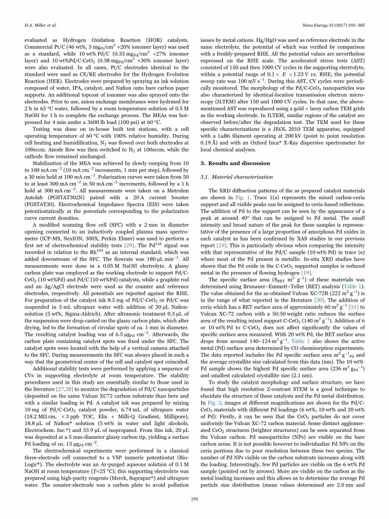
To study the catalyst morphology and surface structure, we havefound that high resolution Z-contrast STEM is a good technique toelucidate the structure of these catalysts and the Pd metal distribution.In Fig. 2, images at different magnifications are shown for the Pd/C-CeO2 materials with different Pd loadings (6 wt%, 10 wt% and 20 wt%of Pd). Firstly, it can be seen that the CeO2 particles do not coveruniformly the Vulcan XC-72 carbon material. Some distinct agglomer-ated CeO2 structures (brighter structures) can be seen separated fromthe Vulcan carbon. Pd nanoparticles (NPs) are visible on the barecarbon areas. It is not possible however to individualize Pd NPs on theceria portions due to poor resolution between these two species. Thenumber of Pd NPs visible on the carbon substrate increases along withthe loading. Interestingly, few Pd particles are visible on the 6 wt% Pdsample (pointed out by arrows). More are visible on the carbon as themetal loading increases and this allows us to determine the average Pdparticle size distribution (mean values determined are 2.0 nm and
H.A. Miller et al. Nano Energy 33 (2017) 293–305
295

2.5 nm for the 10 wt% and 20 wt% samples, respectively).STEM-EDX analysis helps to determine the Pd distribution over the
whole sample including also the ceria portions of the support. Asexample, a representative image of the 20 wt% Pd sample is shown inFig. 3. Two zones are clearly distinguishable. On the right side a purelycarbon portion (in blue) covered with many small Pd NPs (in green).STEM-EDX elemental map analysis shows a large ceria cluster (in red)covering the carbon structure on the left portion of the sample. The Pdmapping shows that although there are many Pd NPs visible on thecarbon section, most of the Pd is actually present on the ceriastructures. STEM-EDX analysis of the sample prepared with 10 wt%Pd shows the same trend with the only difference being that very fewPd nanoparticles are visible on the bare carbon regions (see SI forcomparative analysis). The middle set of TEM images in Fig. 2 alsoshow clearly that there are few Pd nanoparticles visible on the carbonregions for 6 and 10 wt% Pd samples while at 20% loading there ishigher coverage of Pd also on the carbon.
3.2. Electrochemical tests
Electrochemical data are listed in Table 2, including the electro-chemically active surface area (ECSA), exchange current densities (i0)and the mass activity per gram of Pd (i0, m). The mass activity per gram
of Pd is significantly higher for the 10 wt% Pd sample relative to boththe 6 wt% and 20 wt% samples. The Tafel analysis of each catalyst,shown in Fig. 4, also confirms the increased performance of the 10 wt% Pd sample relative to the others. Indeed, increasing the Pd loadingfrom 10% to 20% does not improve the overall activity of the catalyst.Tafel slope analysis reveals a large difference amongst the variouscatalysts with values of 100, 66 and 143 mV dec−1 respectivelysuggesting a change in the HOR mechanism after a doubling of thePd loading 10–20%). A value of 66 mV dec−1 indicates that the ratedetermining step (rds) for the 10% Pd catalyst is molecular hydrogendissociative adsorption (Tafel step), while the 20% Pd sample shows avalue that suggests charge transfer processes are rate limiting [22].
3.3. Fuel cell tests
For fuel cell tests, the Pd/C-CeO2 anode catalysts with different Pdloadings (6 wt%, 10 wt% and 20 wt% Pd) were incorporated into anodecatalyst layers (0.15–0.30 mgPd cm
−2). Three identical cells where theonly change was the anode catalyst layer, were prepared for testing inAEM-FC single cells. Fig. 5 shows the cell performance at 73 °C runwith dry H2 and purified air (~10 ppm CO2). Polarization curves of cellswith anodes made with Pd/C-CeO2 (6 and 20 wt% Pd) were comparedwith the previous reported results made with anodes made with Pd/C-CeO2 10 wt% Pd [19]. As can be seen from Fig. 5, although resultsobtained with all catalysts appear to be similar, the Pd/C-CeO2 10 wt%Pd reported previously shows slightly better performance [19]. Table 3summarizes the fuel cell results.
As shown in Table 3, the performance of the Pd/C-CeO2 10 wt% Pdcatalyst performs slightly better than the other two catalysts withhigher and lower Pd loadings. It seems that the high Pd loading (20 wt%) does not give any beneficial effect on fuel cell performance, asincreasing the amount of Pd from 10 wt% to 20 wt% leads to more Pddeposited on the carbon regions, as discussed previously and alsoshown in Figs. 2 and 3. These isolated Pd on carbon nanoparticles donot contribute to the enhanced activity as they perform as Pd/C, withsignificantly lower performance due to the lack of the advantage of Pd-ceria interactions [19].
Fig. 1. XRD diffraction patterns of (a) 50:50 wt% C-CeO2, (b) Pd/C-CeO2 (6 wt% Pd), (c) Pd/C-CeO2 (10 wt% Pd), (d) Pd/C-CeO2 (20 wt% Pd) and (e) Pd/C (10 wt% Pd). Legend: (•)Pd, (■) CeO2 and (⬟) carbon.
Table 1Physical characterization data obtained from BET experiments and CO-chemisorptionisotherms.
Sample SBET Pd specific surfacearea
Pd particle size
m2 g−1 m2 g−1Pd nm
C (Vulcan XC-72) 222 – –
C-CeO2 (50 wt%CeO2)
140 – –
Pd/C-CeO2 (6 wt%Pd)
141 188 2.6
Pd/C-CeO2 (10 wt%Pd)
145 236 2.1
Pd/C-CeO2 (20 wt%Pd)
124 146 3.4
H.A. Miller et al. Nano Energy 33 (2017) 293–305
296
3.4. Hydrogen pumping tests
A hydrogen pump cell system was developed to test the bestperforming catalyst Pd/C-CeO2 (10 wt%) and compare it to Pd/C(10 wt%) and Pt/C (46 wt%). This system allows us to study the HORactivity of each catalyst under fuel cell type conditions. Fig. 6 shows thepolarization curves for the three materials, demonstrating that the Pd/C-CeO2 material far outperforms the Pd/C catalyst, while showingsimilar performance to that of a Pt/C anode. This is achieved with a Pdmetal loading ~10 times lower than the Pt metal loading (0.33 mgPdcm−2 vs. 3 mgPt cm
−2).As can be seen, the performance of the Pd/C-CeO2 catalyst is clearly
superior to that obtained with Pd/C. For instance, at 0.4 V and 0.8 Vthe current densities obtained with Pd/C-CeO2 were around threetimes higher than the current densities obtained with Pd/C. Theseresults confirm the higher activity of Pd/C-CeO2 as compared to Pd/C(without ceria) as has also been shown in fuel cell tests [19].
Fig. 7 shows the steady state performance of a hydrogen pumpingcell run at constant 300 mA cm−2 over the course of 1 h. While the Pd/C shows an increase in potential during test, Pd/C-CeO2 (as well as Pt/C) shows a very stable performance at a much lower potential. Theseresults indicate that the addition of ceria support to the catalystimproves not just the performance, but also the stability of the catalyst.
Electrochemical Impedance Spectroscopy (EIS) spectra were takenfor all three HOR catalysts. Fig. 8 summarizes these results for J=300 mA cm−2. All three materials showed negative shifts in the high-frequency resistance (HFR) as the current density increased. The shiftin the Pt/C HFR was significantly larger (~25 mΩ) that either the Pd/C
(~5 mΩ) or the Pd/C-CeO2 (~15 mΩ). The charge transfer resistance(approximated by the distance between to the two y-intercepts) of thePt/C was less than that of either of the two Pd-based materials.However, the Pd/C-CeO2 did show an improvement over the Pd/Ccatalyst. Additionally, the HFR of the Pd/C-CeO2 catalyst was verysimilar to that of the Pt/C reference.
3.5. Stability tests
To further evaluate the stability of Pd/C-CeO2, electrochemical testswere performed using a modified SFC to measure the dissolutionproperties of the 10 wt% Pd/C-CeO2 catalyst in alkaline mediumcompared to Pd/C. To get a first insight on the stability of the studiedcatalysts in alkaline media, CVs in a broad potential window (−0.05 to1.4 VRHE) of Pd oxide formation and reduction as well as hydrogensorption and desorption were recorded in Ar-saturated 0.05 M NaOHelectrolyte. The results are summarized in Fig. 9.
In Fig. 9 the upper pane shows variation of potential with time. Thiscontains a short stay at the open circuit potential (OCV), fast cleaningcycles, two cycles recorded at 50 mV s−1, short potentiostating at−0.05VRHE, and a slow scan at 5 mV s−1. The latter is added for aclear separation between anodic and cathodic dissolution processes,well known for corrosion of other noble metals in acid and base [32].Dissolution is shown in the lower pane in Fig. 9. By comparing the Pd/C-CeO2 catalyst with Pd/C one can clearly see that the OCV is slightlylower, while more Pd is detected in this region for Pd/C-CeO2. This canbe an indication of the cathodic dissolution of an unstable Pd oxide,which is consistent with the fact that Pd oxide is found in the Pd/C-
Fig. 2. Comparison between the three Pd loadings (A 6%, B 10% and C 20%) at three different magnifications: scale bar of the first line is 200 nm, middle line 100 nm and bottom line50 nm.
H.A. Miller et al. Nano Energy 33 (2017) 293–305
297

Fig. 3. STEM-EDX analysis of a representative portion of the 20 wt% Pd catalyst. (For interpretation of the references to color in this figure, the reader is referred to the web version ofthis article.)
Table 2Electrochemical characterization data.
Pd content in Pd/C-CeO2 i0 ECSA Tafel slope i0, mwt% µA cmPd
−2 m2 g−1Pd mV dec−1 A gPd−2
6 89 22 100 1910 55 43 66 2420 83 14 143 11
Fig. 4. Tafel slope analysis of Pd/C-CeO2 (6 wt%, 10 wt% and 20 wt% Pd) obtained inH2-saturated 0.1 M KOH at 10 mV s−1 and 1600 rpm.
Fig. 5. Polarization curves of AEM-FCs using Pd/C-CeO2 anode catalysts with 10 wt%Pd [19], 6%Pd and 20 wt%.
Table 3H2/air AEM-FC polarization data summary.
Current density at 0.85 V Peak power densitymA cm−2 mW cm−2
Pd/C-CeO2 10 wt%Pd [19] 100 500Pd/C-CeO2 6 wt%Pd 90 390Pd/C-CeO2 20 wt%Pd 80 460
H.A. Miller et al. Nano Energy 33 (2017) 293–305
298

CeO2 catalyst before flowing hydrogen, which reduces the oxide layer toPd metal (see Section 3.1). Since also some cerium dissolution wasobserved in this region (see Fig. S2), it can be assumed that the two
processes are related, as it was found that Pd was preferable depositedon ceria regions (see Section 3.1). It has to be remarked though, thatthe observed signal must be due to dissolution but not particledetachments as in the latter case the dissolution rates of Pd and Ceshould scale linearly.
From Fig. 9 it can be also seen that the Pd/C-CeO2 catalyststabilizes with potential cycling, although the detection of Pd by ICP-MS is still non-zero. The contrary is observed for Pd/C where Pddetection from this electrode significantly increases with potentialcycling. The origin of the detection of Pd can here originate both fromdissolution of the Pd nanoparticles or from their detachment from thecarbon support, the latter having been found non-negligible in NaOHelectrolytes by ILTEM experiments [27]. The total amount of Pd lostfrom both electrodes during the OCV and the potential cycling is ca.1.4 ng, which is 3% of the initial loading. Both electrodes are stabilizedduring the following potential step at −0.05 VRHE. When potentialsmove into anodic direction, Pd starts to dissolve from both electrodes.Interestingly, the onset of Pd dissolution from Pd/C-CeO2 is signifi-cantly lower that for Pd/C (see inset in Fig. 9), suggesting a differentmechanism (or different kinetics) of Pd loss. Even if initiated later, Pd/C dissolution however, shows much higher dissolution rates (up to anorder of magnitude) at the higher potentials. At even higher potentialsPd passivates, likely due to formation of a stable oxide. Some increasein dissolution is also observed during oxide reduction, although the
Fig. 6. Polarization curves of hydrogen pumping tests comparing the HOR performanceof Pd/C-CeO2 to both Pd/C as well as Pt/C.
Fig. 7. Stability run of hydrogen pumping tests of Pd/C-CeO2 catalyst as compared toboth Pd/C and Pt/C under 300 mA cm−2 steady state operation.
Fig. 8. EIS measured during hydrogen pumping tests at a current density of 300 mA cm2. Right plot shows a zoom-in of the left plot.
Fig. 9. Pd detection profiles of Pd/C and Pd/C-CeO2 (both 10 wt% Pd) during 10 cyclesat 200 mV s−1, 2 cycles at 50 mV s−1 and 1 cycle at 5 mV s−1, in the range of −0.05 to 1.4VRHE in 0.05 M NaOH purged with Argon.
H.A. Miller et al. Nano Energy 33 (2017) 293–305
299
amounts are lower. As previously indicated, the reason for the superiorstability of Pd/C-CeO2 may be a strong Pd-ceria interaction. Asdemonstrated by STEM and XAS investigations in our recent article
most of the Pd nanoparticles are supported on the CeO2 (and not oncarbon) [19], and are therefore not subjected to the harsh nanoparticledetachment that occurs for carbon-supported Pd/C nanoparticles. Thishypothesis will be explored by ILTEM experiments (see below).
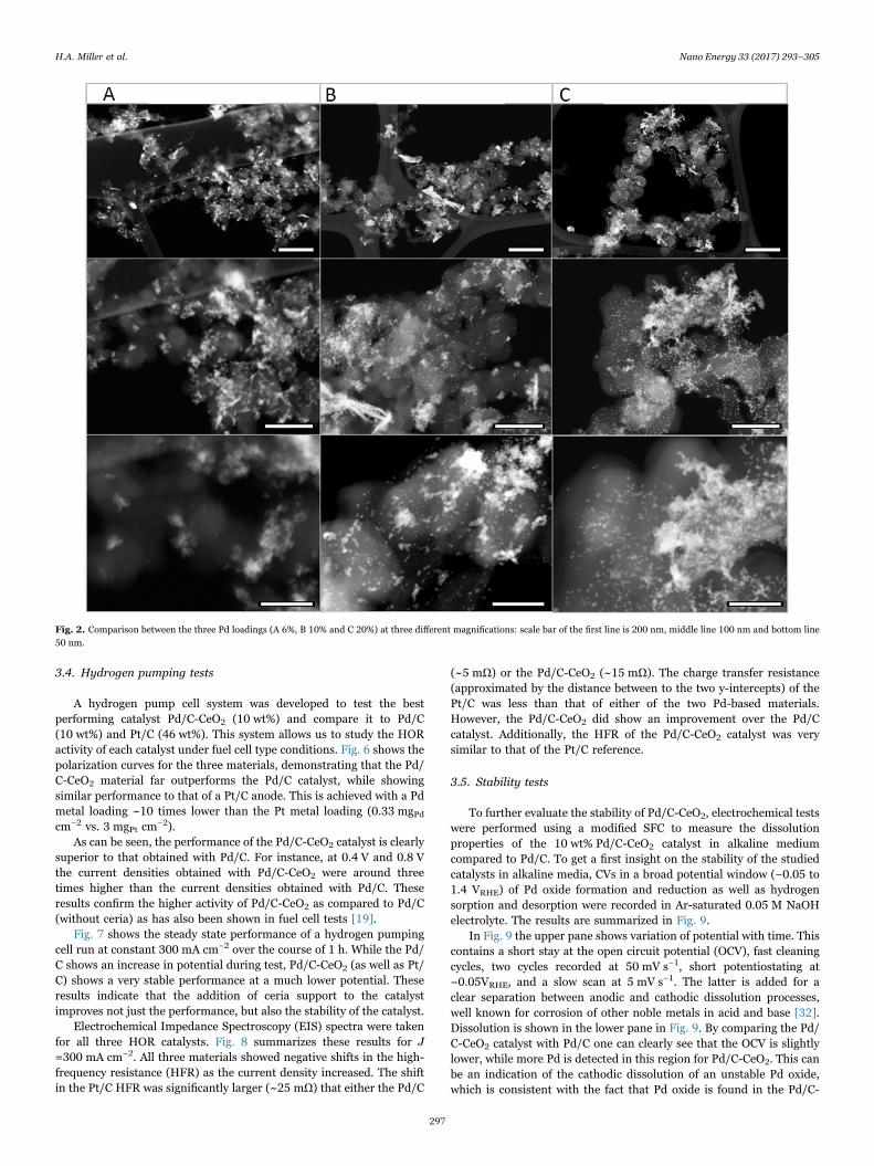
It is anticipated that during normal operation of an AEM-FC thehighest anodic potential the anode will experience is the potential atopen circuit (0.9–1.0 V vs RHE), which is significantly lower than theupper potential limit of cycling used in the experiments presented inFig. 9 (=1.4 V vs RHE). Also, as hydrogen can influence (reduce) the Pdoxide layer of the Pd/C-CeO2 catalyst, a second protocol shown inFig. 10 was used to investigate Pd stability at much more realisticconditions (better simulating an AEM-FC environment). In this case,the upper potential limit was moved to 1.0 VRHE and the cleaning cycleswere excluded. Moreover, dissolution was studied in argon as well as inhydrogen, to test if hydrogen influences stability and to see if theimproved activity of Pd/C-CeO2 towards HOR holds also in SFC tests.
For both electrodes, the dissolution behavior during the OCV andpotential cycling in argon is analogous to that discussed above.Furthermore, no significant difference was observed when the gaswas switched to hydrogen. In hydrogen, Pd behaves similarly to Pt inacid [33]. The inset in Fig. 10 presents a magnified view of thedissolution profile, where it can be clearly seen that the amount ofPd dissolved from Pd/C-CeO2 is significantly lower as compared to thatdissolved from Pd/C, indicating that the stability of the Pd/C-CeO2 isremarkable higher than the stability of Pd/C. In this region, theestimated amount of dissolved Pd was 50 pg and 5 pg for Pd/C andPd/C-CeO2, respectively. Hence, assuming that dissolution rate is notchanging with material consumption (a very rough estimation) all Pdshould be completely dissolved in 3000 and 30,000 cycles up to 1.0VRHE from the Pd/C and Pd/C-CeO2 electrodes, respectively. Theseresults suggest that the excellent stability of the Pd/C-CeO2 may berelated to the Pd-ceria interaction.
To further examine the stability of the Pd/C-CeO2 catalyst andinvestigate the mechanisms of degradation of these materials, CV cyclingtests were also performed and analyzed. Fig. 11 presents a sequence ofCVs obtained on the Pd/C-CeO2 (10 wt%Pd) catalyst upon aging in 0.1 MNaOH (at 25 °C) supporting electrolyte. It can be seen that the overallshape of the CV is very similar to that obtained on the same material in0.1 M KOH, previously reported [19], although in that latter case, thepeak related to Pd-oxides reduction was more pronounced, because theupper vertex potential was larger (1.3 V vs. RHE instead of 1.4 V vs. RHE)and the scan rate value was lower. One also clearly sees that the signatureof Pd-hydrides and Pd-oxides gradually level off upon cycling.
Fig. 10. Dissolution profiles of Pd/C and Pd/C-CeO2 (10 wt%Pd) during cycling at50 mV s−1 in the range of −0.05 to 1.0 VRHE in 0.05 M NaOH purged with argon (in first,green left area) and then with hydrogen (in second, red right area). (For interpretation ofthe references to color in this figure legend, the reader is referred to the web version ofthis article.)
Fig. 11. CVs monitored on the Pd/C-CeO2 (10 wt%Pd) catalyst upon aging in 0.1 MNaOH supporting electrolyte at 25 °C.
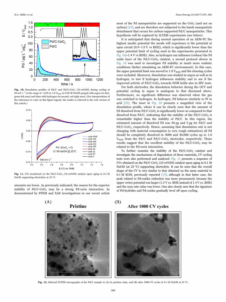
Fig. 12. Selected ILTEM micrographs of the Pd/C sample in (A) its pristine state, and (B) after 1000 CV cycles in 0.1 M NaOH at 25 °C.
H.A. Miller et al. Nano Energy 33 (2017) 293–305
300
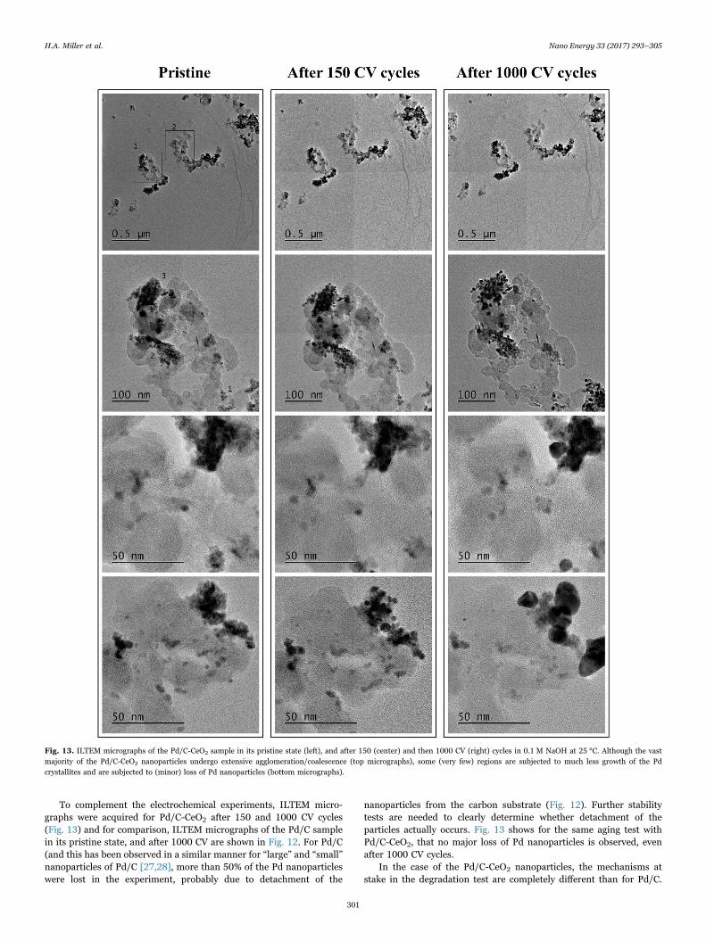
To complement the electrochemical experiments, ILTEM micro-graphs were acquired for Pd/C-CeO2 after 150 and 1000 CV cycles(Fig. 13) and for comparison, ILTEM micrographs of the Pd/C samplein its pristine state, and after 1000 CV are shown in Fig. 12. For Pd/C(and this has been observed in a similar manner for “large” and “small”nanoparticles of Pd/C [27,28], more than 50% of the Pd nanoparticleswere lost in the experiment, probably due to detachment of the
nanoparticles from the carbon substrate (Fig. 12). Further stabilitytests are needed to clearly determine whether detachment of theparticles actually occurs. Fig. 13 shows for the same aging test withPd/C-CeO2, that no major loss of Pd nanoparticles is observed, evenafter 1000 CV cycles.
In the case of the Pd/C-CeO2 nanoparticles, the mechanisms atstake in the degradation test are completely different than for Pd/C.
Fig. 13. ILTEM micrographs of the Pd/C-CeO2 sample in its pristine state (left), and after 150 (center) and then 1000 CV (right) cycles in 0.1 M NaOH at 25 °C. Although the vastmajority of the Pd/C-CeO2 nanoparticles undergo extensive agglomeration/coalescence (top micrographs), some (very few) regions are subjected to much less growth of the Pdcrystallites and are subjected to (minor) loss of Pd nanoparticles (bottom micrographs).
H.A. Miller et al. Nano Energy 33 (2017) 293–305
301
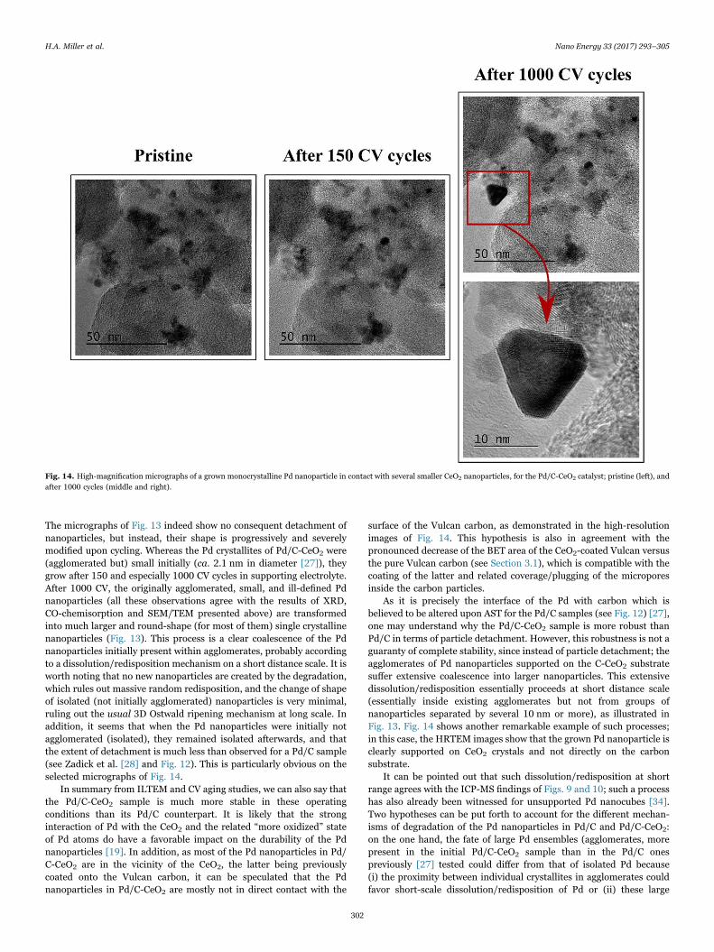
The micrographs of Fig. 13 indeed show no consequent detachment ofnanoparticles, but instead, their shape is progressively and severelymodified upon cycling. Whereas the Pd crystallites of Pd/C-CeO2 were(agglomerated but) small initially (ca. 2.1 nm in diameter [27]), theygrow after 150 and especially 1000 CV cycles in supporting electrolyte.After 1000 CV, the originally agglomerated, small, and ill-defined Pdnanoparticles (all these observations agree with the results of XRD,CO-chemisorption and SEM/TEM presented above) are transformedinto much larger and round-shape (for most of them) single crystallinenanoparticles (Fig. 13). This process is a clear coalescence of the Pdnanoparticles initially present within agglomerates, probably accordingto a dissolution/redisposition mechanism on a short distance scale. It isworth noting that no new nanoparticles are created by the degradation,which rules out massive random redisposition, and the change of shapeof isolated (not initially agglomerated) nanoparticles is very minimal,ruling out the usual 3D Ostwald ripening mechanism at long scale. Inaddition, it seems that when the Pd nanoparticles were initially notagglomerated (isolated), they remained isolated afterwards, and thatthe extent of detachment is much less than observed for a Pd/C sample(see Zadick et al. [28] and Fig. 12). This is particularly obvious on theselected micrographs of Fig. 14.
In summary from ILTEM and CV aging studies, we can also say thatthe Pd/C-CeO2 sample is much more stable in these operatingconditions than its Pd/C counterpart. It is likely that the stronginteraction of Pd with the CeO2 and the related “more oxidized” stateof Pd atoms do have a favorable impact on the durability of the Pdnanoparticles [19]. In addition, as most of the Pd nanoparticles in Pd/C-CeO2 are in the vicinity of the CeO2, the latter being previouslycoated onto the Vulcan carbon, it can be speculated that the Pdnanoparticles in Pd/C-CeO2 are mostly not in direct contact with the
surface of the Vulcan carbon, as demonstrated in the high-resolutionimages of Fig. 14. This hypothesis is also in agreement with thepronounced decrease of the BET area of the CeO2-coated Vulcan versusthe pure Vulcan carbon (see Section 3.1), which is compatible with thecoating of the latter and related coverage/plugging of the microporesinside the carbon particles.
As it is precisely the interface of the Pd with carbon which isbelieved to be altered upon AST for the Pd/C samples (see Fig. 12) [27],one may understand why the Pd/C-CeO2 sample is more robust thanPd/C in terms of particle detachment. However, this robustness is not aguaranty of complete stability, since instead of particle detachment; theagglomerates of Pd nanoparticles supported on the C-CeO2 substratesuffer extensive coalescence into larger nanoparticles. This extensivedissolution/redisposition essentially proceeds at short distance scale(essentially inside existing agglomerates but not from groups ofnanoparticles separated by several 10 nm or more), as illustrated inFig. 13. Fig. 14 shows another remarkable example of such processes;in this case, the HRTEM images show that the grown Pd nanoparticle isclearly supported on CeO2 crystals and not directly on the carbonsubstrate.
It can be pointed out that such dissolution/redisposition at shortrange agrees with the ICP-MS findings of Figs. 9 and 10; such a processhas also already been witnessed for unsupported Pd nanocubes [34].Two hypotheses can be put forth to account for the different mechan-isms of degradation of the Pd nanoparticles in Pd/C and Pd/C-CeO2:on the one hand, the fate of large Pd ensembles (agglomerates, morepresent in the initial Pd/C-CeO2 sample than in the Pd/C onespreviously [27] tested could differ from that of isolated Pd because(i) the proximity between individual crystallites in agglomerates couldfavor short-scale dissolution/redisposition of Pd or (ii) these large
Fig. 14. High-magnification micrographs of a grown monocrystalline Pd nanoparticle in contact with several smaller CeO2 nanoparticles, for the Pd/C-CeO2 catalyst; pristine (left), andafter 1000 cycles (middle and right).
H.A. Miller et al. Nano Energy 33 (2017) 293–305
302
ensembles could have more anchoring points to the substrate. On theother hand, as previously hypothesized, it can be that the stability ofthe Pd/C-CeO2 nanoparticles are uniquely linked to the proximity of Pdto the CeO2 phase (anchoring points of the Pd nanoparticles to theVulcan carbon (see Fig. 12), which are prone to destruction in theseconditions, are replaced by tougher anchoring points to the CeO2
surface, see Fig. 14), again in agreement with the findings of ICP-MS.More studies are necessary to understand precisely the mechanisms ofdegradation of these materials, but this does not put into question themuch enhanced durability of the Pd/C-CeO2 nanoparticles noted herecompared to Pd/C catalysts.
4. Conclusions
We report a new class of bifunctional electrocatalyst for thehydrogen oxidation reaction in fuel cells under alkaline conditions.The electrocatalysts, denoted Pd/C-CeO2, consist of deposited Pdnanoparticles on a support mixture of 50:50 carbon and CeO2. ThePd is preferentially deposited on the ceria regions of the support.Previous reports on AEM-FCs as well as the hydrogen pump testsdescribed in this report show that the Pd/C-CeO2 catalyst hassignificantly higher activity than Pd/C towards the HOR in alkalinemedium. In addition, we have performed preliminary stability studieson Pd/C-CeO2 showing that catalyst stability under harsh potentialcycling is improved as compared to Pd/C. To the best of our under-standing, the Pd/C-CeO2 bifunctional material studied in this report isthe HOR electrocatalyst with highest activity and stability for AEM-FCsso far developed.
Acknowledgements
We acknowledge the Ente Cassa di Risparmio di Firenze ITALY(projects HYDROLAB2 and EnergyLab) for financial support. Thiswork was also partially funded by the Grand Technion Energy Program(GTEP); by the European Commission through H2020 Grant No.NMBP-03-2016 CREATE project; by the Ministry of Science,Technology & Space of Israel through the M.era-NET TransnationalCall 2015, NEXTGAME project; and by the Israel National ResearchCenter for Electrochemical Propulsion (INREP-ISF).
Appendix A. Supporting information
Supporting information associated with this article can be found inthe online version at doi:10.1016/j.nanoen.2017.01.051.
References
[1] J.R. Varcoe, P. Atanassov, D.R. Dekel, A.M. Herring, M.A. Hickner, P.A. Kohl,A.R. Kucernak, W.E. Mustain, K. Nijmeijer, K. Scott, T.W. Xu, L. Zhuang, Anion-exchange membranes in electrochemical energy systems, Energy Environ. Sci. 7(2014) 3135–3191.
[2] Y.S. Li, T.S. Zhao, A passive anion-exchange membrane direct ethanol fuel cellstack and its applications, Int J. Hydrog. Energy 41 (2016) 20336–20342.
[3] Y.S. Li, Y.L. He, An all-in-one electrode for high-performance liquid-feed micropolymer electrolyte membrane fuel cells, J. Electrochem. Soc. 163 (2016)F663–F667.
[4] Y.S. Li, J.H. Lv, Y.L. He, A monolithic carbon foam-supported Pd-based catalysttowards ethanol electro-oxidation in alkaline media, J. Electrochem. Soc. 163(2016) F424–F427.
[5] Y.S. Li, A liquid-electrolyte-free anion-exchange membrane direct formate-per-oxide fuel cell, Int J. Hydrog. Energy 41 (2016) 3600–3604.
[6] Y.S. Li, H. Wu, Y.L. He, Y. Liu, L. Jin, Performance of direct formate-peroxide fuelcells, J. Power Sources 287 (2015) 75–80.
[7] Y.S. Li, Y.L. He, W.W. Yang, A high-performance direct formate-peroxide fuel cellwith palladium-gold alloy coated foam electrodes, J. Power Sources 278 (2015)569–573.
[8] Y.S. Li, Y.L. He, Layer reduction method for fabricating Pd-coated Ni foams ashigh-performance ethanol electrode for anion-exchange membrane fuel cells, RSC
Adv. 4 (2014) 16879–16884.[9] J. Ponce-Gonzalez, D.K. Whelligan, L. Wang, R. Bance-Soualhi, Y. Wang, Y. Peng,
H. Peng, D.C. Apperley, H.N. Sarode, T.P. Pandey, A.G. Divekar, S. Seifert,A.M. Herring, L. Zhuang, J.R. Varcoe, High performance aliphatic-heterocyclicbenzyl-quaternary ammonium radiation-grafted anion-exchange membranes,Energy Environ. Sci. 9 (2016) 3724–3735.
[10] L. Wang, E. Magliocca, E.L. Cunningham, W.E. Mustain, S.D. Poynton,R. Escudero-Cid, M.M. Nasef, J. Ponce-Gonzalez, R. Bance-Souahli, R.C.T. Slade,D.K. Whelligan, J.R. Varcoe, An optimised synthesis of high performance radiation-grafted anion-exchange membranes, Green Chem. (2017). http://dx.doi.org/10.1039/c6gc02526a.
[11] E.F. Holby, P. Zelenay, Linking structure to function: the search for active sites innon-platinum group metal oxygen reduction reaction catalysts, Nano Energy 29(2016) 54–64.
[12] O.V. Korchagin, V.A. Bogdanovskaya, M.R. Tarasevich, A.V. Kuzov, G.V. Zhutaeva,M.V. Radina, V.T. Novikov, V.V. Zharikov, Characteristics of non-platinum cathodecatalysts for a hydrogen-oxygen fuel cell with proton- and anion-conductingelectrolytes, Catal. Ind. 8 (2016) 265–273.
[13] K. Strickland, M.W. Elise, Q.Y. Jia, U. Tylus, N. Ramaswamy, W.T. Liang,M.T. Sougrati, F. Jaouen, S. Mukerjee, Highly active oxygen reduction non-platinum group metal electrocatalyst without direct metal-nitrogen coordination,Nat. Commun. 6 (2015).
[14] A. Amel, N. Gavish, L. Zhu, D.R. Dekel, M.A. Hickner, Y. Ein-Eli, Bicarbonate andchloride anion transport in anion exchange membranes, J. Membr. Sci. 514 (2016)125–134.
[15] A. Amel, S.B. Smedley, D.R. Dekel, M.A. Hickner, Y. Ein-Eli, Characterization andchemical stability of anion exchange membranes cross-linked with polar electron-donating linkers, J. Electrochem Soc. 162 (2015) F1047–F1055.
[16] D.R. Dekel, Alkaline membrane fuel cell (AMFC) materials and system improve-ment - state-of-the-art, ECS Trans. 50 (2013) 2051–2052.
[17] J. Durst, A. Siebel, C. Simon, F. Hasche, J. Herranz, H.A. Gasteiger, New insightsinto the electrochemical hydrogen oxidation and evolution reaction mechanism,Energy Environ. Sci. 7 (2014) 2255–2260.
[18] M. Alesker, M. Page, M. Shviro, Y. Paska, G. Gershinsky, D.R. Dekel, D. Zitoun,Palladium/nickel bifunctional electrocatalyst for hydrogen oxidation reaction inalkaline membrane fuel cell, J. Power Sources 304 (2016) 332–339.
[19] H.A. Miller, A. Lavacchi, F. Vizza, M. Marelli, F. Di Benedetto, F.D.I. Acapito,Y. Paska, M. Page, D.R. Dekel, A Pd/C-CeO2 anode catalyst for high-performanceplatinum-free anion exchange membrane fuel cells, Angew. Chem. Int. Ed. 55(2016) 6004–6007.
[20] D. Strmcnik, M. Uchimura, C. Wang, R. Subbaraman, N. Danilovic, D. van derVliet, A.P. Paulikas, V.R. Stamenkovic, N.M. Markovic, Improving the hydrogenoxidation reaction rate by promotion of hydroxyl adsorption, Nat. Chem. 5 (2013)300–306.
[21] Y. Wang, G.W. Wang, G.W. Li, B. Huang, J. Pan, Q. Liu, J.J. Han, L. Xiao, J.T. Lu,L. Zhuang, Pt-Ru catalyzed hydrogen oxidation in alkaline media: oxophilic effector electronic effect?, Energy Environ. Sci. 8 (2015) 177–181.
[22] S. St John, R.W. Atkinson, R.R. Unocic, T.A. Zawodzinski, A.B. Papandrew,Ruthenium-alloy electrocatalysts with tunable hydrogen oxidation kinetics inalkaline electrolyte, J. Phys. Chem. C 119 (2015) 13481–13487.
[23] S. Cherevko, A.R. Zeradjanin, A.A. Topalov, N. Kulyk, I. Katsounaros,K.J.J. Mayrhofer, Dissolution of noble metals during oxygen evolution in acidicmedia, Chemcatchem 6 (2014) 2219–2223.
[24] B.R. Shrestha, A. Nishikata, T. Tsuru, Channel flow double electrode study onpalladium dissolution during potential cycling in sulfuric acid solution,Electrochim. Acta 70 (2012) 42–49.
[25] J.F. Llopis, J.M. Gamboa, L. Victori, Electrochim. Acta 17 (1972) 2225–2230.[26] A.E. Bolzan, Phenomenological aspects related to the electrochemical-behavior of
smooth palladium electrodes in alkaline-solutions, J. Electroanal. Chem. 380(1995) 127–138.
[27] A. Zadick, L. Dubau, U.B. Demirci, M. Chatenet, Effects of Pd nanoparticle size andsolution reducer strength on Pd/C electrocatalyst stability in alkaline electrolyte, J.Electrochem. Soc. 163 (2016) F781–F787.
[28] A. Zadick, L. Dubau, N. Sergent, G. Berthome, M. Chatenet, Huge instability of Pt/Ccatalysts in alkaline medium, ACS Catal. 5 (2015) 4819–4824.
[29] S.O. Klemm, A.A. Topalov, C.A. Laska, K.J.J. Mayrhofer, Coupling of a highthroughput microelectrochemical cell with online multielemental trace analysis byICP-MS, Electrochem. Commun. 13 (2011) 1533–1535.
[30] Y. Holade, C. Morais, K. Servat, T.W. Napporn, K.B. Kokoh, Enhancing theavailable specific surface area of carbon supports to boost the electroactivity ofnanostructured Pt catalysts, Phys. Chem. Chem. Phys. 16 (2014) 25609–25620.
[31] N. Laosiripojana, S. Assabumrungrat, The effect of specific surface area on theactivity of nano-scale ceria catalysts for methanol decomposition with and withoutsteam at SOFC operating temperatures, Chem. Eng. Sci. 61 (2006) 2540–2549.
[32] S. Cherevko, A.R. Zeradjanin, G.P. Keeley, K.J.J. Mayrhofer, A Comparative studyon gold and platinum dissolution in acidic and alkaline media, J. Electrochem. Soc.161 (2014) H822–H830.
[33] A.A. Topalov, A.R. Zeradjanin, S. Cherevko, K.J.J. Mayrhofer, The impact ofdissolved reactive gases on platinum dissolution in acidic media, Electrochem.Commun. 40 (2014) 49–53.
[34] A. Zadick, L. Dubau, A. Zalineeva, C. Coutanceau, M. Chatenet, When cubicnanoparticles get spherical: an identical location transmission electron microscopycase study with Pd in alkaline media, Electrochem. Commun. 48 (2014) 1–4.
H.A. Miller et al. Nano Energy 33 (2017) 293–305
303
Hamish Andrew Miller is a researcher at the ICCOMinstitute of the CNR based in Florence, Italy. After receiv-ing his PhD in inorganic chemistry from the Queen’sUniversity of Belfast (UK) in 1999, he spent 10 yearsworking in the chemical industry including 6 years devel-oping fuel cells and electrolyzers. His major researchinterests involve nanotechnology and electrocatalysis inenergy related fields. In particular developing non PGMelectrocatalysts for alkaline anion exchange membrane fuelcells, electroreforming of renewable alcohols for co-pro-duction of chemicals and hydrogen and investigating theelectrochemical reduction of CO2 to fuels and chemicals.
Dr. Francesco Vizza is Research Director at the ICCOM-CNR, Florence, Italy and the scientific director of alaboratory of advanced materials for energy (LAME@ICCOM). At the LME@ICCOM research activities, includethe synthesis of catalysts for fuel cells (DAFC and PEMFC),evolution of hydrogen by electrolysis from renewables, CO2
conversion in fuels or chemicals, development of photo-catalysts for H2 evolution, catalysts for hydrogen evolutionby controlled hydrolysis or thermolysis of metal hydrides,recovery of metals from waste lithium batteries. He isauthor of 170 peer-reviewed publications in qualifiedinternational journals, 33 patents, 2 monographs and 8chapters in specialized books.
Marcello Marelli received his master degree in AnalyticalChemistry in 2005 and his PhD in Chemical Science in2008 from the University of Insubria (Como, Italy). From2009 worked at ISTM-CNR in Milan as post-doc researcherin the heterogeneous catalysis group for energy applica-tions and chemical industry. From 2017 is a researchscientist in the same group. His work is focused on theadvanced morphological and chemical structure character-ization of nanostructured materials for catalysis, photo-catalysis and electrocatalysis via electron microscopy TEMand SEM.
Anicet ZADICK received in 2016 his PhD in electrocatalysisfrom Grenoble-Alpes University (France) under the super-vision of Marian CHATENET and Christophe GEANTET.His PhD research focused on hydrogen storage alternativesand non-precious electrocatalysts for the direct electroox-idation of hydrazine borane in alkaline media. He is nowworking as energy storage specialist in the private sector.
Laetitia Dubau received her PhD on Electrocatalysis fromPoitiers University (France) under the supervision ofClaude Lamy and Jean-Michel Léger. After five years ofpost-doctoral researches on durability of PEMFC electro-catalysts in the Interfacial Electrochemistry group ofGrenoble University (France), she became a CNRS re-searcher in 2014 in the same team. Her research interestsfocus on understanding the activity/stability relationshipsin electrocatalysis and on the design of electrocatalysts withlow precious metal content.
Marian Chatenet graduated as an engineer in materialssciences and a master in electrochemistry in 1997 from theGrenoble Institute of Technology (Grenoble-INP). He de-fended his PhD in Electrochemistry in 2000 (Grenoble-INP) and then moved to the University of Minnesota until2002 as a post-doctoral fellow in chemical engineering. Hewas appointed associate professor in Grenoble-INP in2002, as a teacher in electrochemistry and a researcher inelectrocatalysis, and is now professor in the same institute.His research topics deal with electrocatalysis of complexreactions and activity/durability of electrocatalysts, inparticular for fuel cell applications.
Simon Geiger studied chemistry at the University ofStuttgart and received his MSc in 2014. Since then he isPhD candidate in the electrocatalysis group of Dr. Karl J.J.Mayrhofer at the Max-Planck-Institut für Eisenforschung.His research activities focus on electrochemical stability ofiridium based materials for the oxygen evolution reaction.
Serhiy Cherevko received his PhD from the SungkyunkwanUniversity in 2009, where he remained until 2011. He thenspent four years with Prof. K.J.J. Mayrhofer at the Max-Planck-Institut für Eisenforschung before becoming a teamleader at Forschungszentrum Jülich. His research interestsfocus on stability of electrocatalyst materials, fundamentalunderstanding of the electrocatalyst degradation mechan-isms, and development of new experimental techniques forelectrocatalysis.
Huong Doan graduated on May 2014 from Worcester StateUniversity, Worcester, MA. She is in her third year ofpursuing her Ph.D at Mukerjee's lab (NUCRET, Boston,MA). Her previous publication focused on a non-PGM OERcatalyst, Ni-Fe (Co)/ Raney-PANI, which was published onNovember 2015. She also has experience on developingand optimizing the water splitting cell system, with themain purpose of producing hydrogen gas at low cost inalkaline media, using non-PGM OER and HER catalysts(both were developed at NUCRET). Two of her currentprojects are funded by the DoE and partnered with ProtonOn-Site (Connecticut) and Pajarito (New Mexico).
Ryan K. Pavlicek got his Bachelors of Science fromCarnegie Mellon University in 2011, and has since been aPhD Candidate at Northeastern University in Boston, MA,working under the direction of Prof. Sanjeev Mukerjee aswell as the Northeastern University Center for RenewableEnergy Technology (NUCRET). His primary research focushas been the use of non-precious metal catalysts in fuelcells, primarily funded through the Department of Energy.His work has involved the study of catalysts for both theHydrogen Oxidation Reaction (HOR) and the OxygenReduction Reaction (ORR) in PEMFCs, HT-PEMFCs, andAEMFCs, focusing on performance, stability, and theinvestigation of mass transport effects.
H.A. Miller et al. Nano Energy 33 (2017) 293–305
304

Dr. Sanjeev Mukerjee is a Distinguished Professor ofChemistry and Chemical Biology at NortheasternUniversity in Boston, MA. The research activity in Prof.Mukerjee's group is an interdisciplinary approach encom-passing the areas of solid state chemistry, spectroscopy,and electrochemistry of electrode materials for electroche-mical energy conversion and storage. The current focus istargeted towards technologies for proton exchange mem-brane (PEM) fuel cells and for batteries, encompassingelectrocatalysis of oxygen reduction, CO tolerance andmethanol oxidation reactions, elevated temperature poly-mer electrolyte membranes, advanced rechargeable bat-teries with nickel metal hydrides and lithium insertion
electrodes for lithium ion and lithium polymer batteries.
Dario R. Dekel is an Associate Professor of ChemicalEngineering Department at Technion, Israel Institute ofTechnology. Prof. Dekel investigates novel cutting-edgematerials and processes for the development of advancedelectrochemical devices, such as novel fuel cells, as well asother technologies for energy storage and generation. Prof.Dekel's current focus involves research of anion conductingionomeric materials, non-PGM electrocatalysts, anion ex-change membranes, anion transport through electroche-mical cells, and fuel cells. Dekel's research team is one ofthe few groups worldwide leading the research on materialsdesign for anion exchange membrane fuel cell technology.
H.A. Miller et al. Nano Energy 33 (2017) 293–305
305