Nachtfee - cdvandt.org signal onto the Nachtfee internal time-reference by setting the. ... when the...
87
www.cdvandt.org Nachtfee
Transcript of Nachtfee - cdvandt.org signal onto the Nachtfee internal time-reference by setting the. ... when the...

www.cdvandt.org
Nachtfee

Photo on EBay early 2005
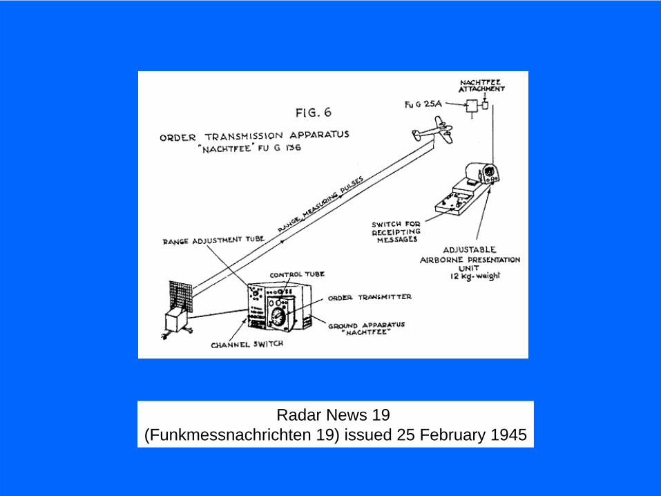
Radar News 19 (Funkmessnachrichten 19) issued 25 February 1945
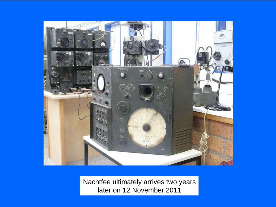
Nachtfee ultimately arrives two yearslater on 12 November 2011
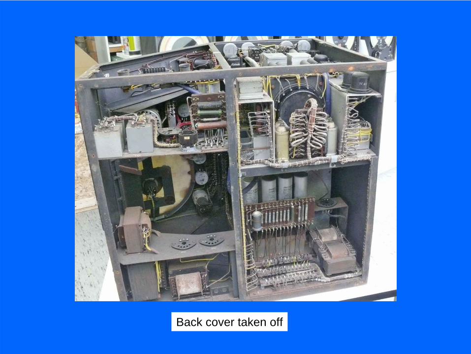
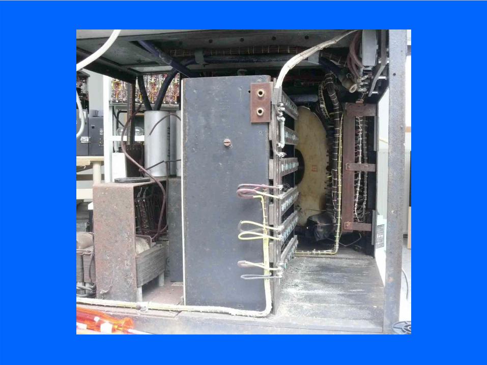
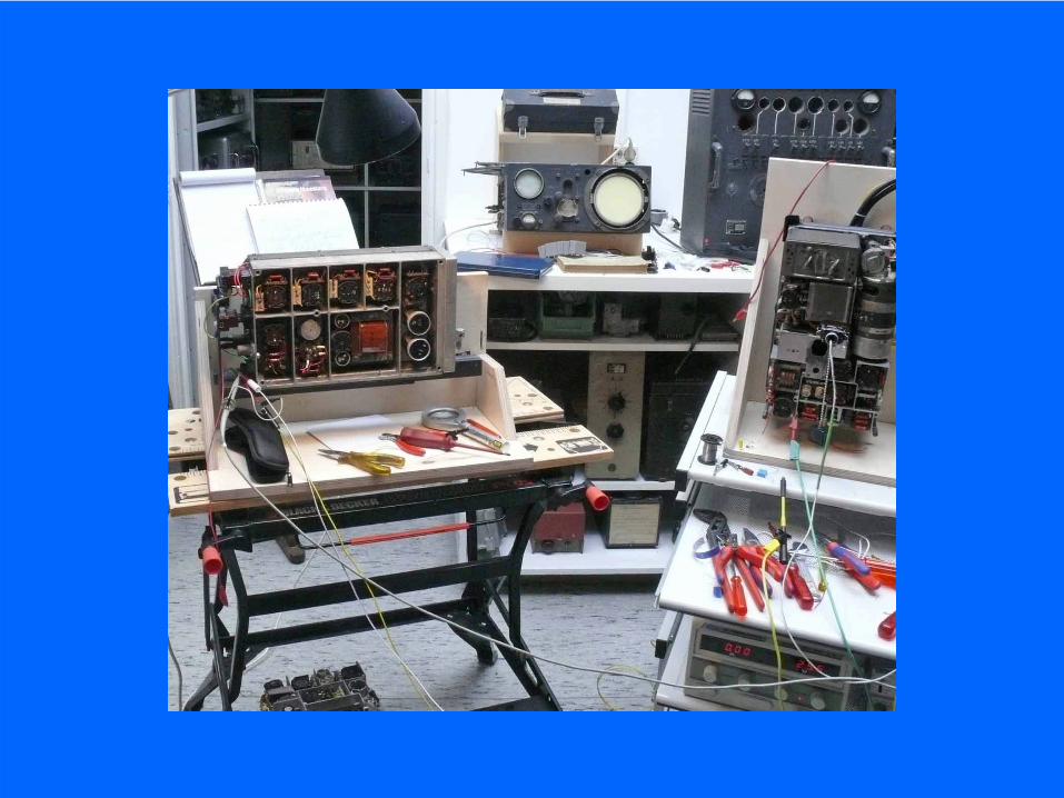
Back cover taken off
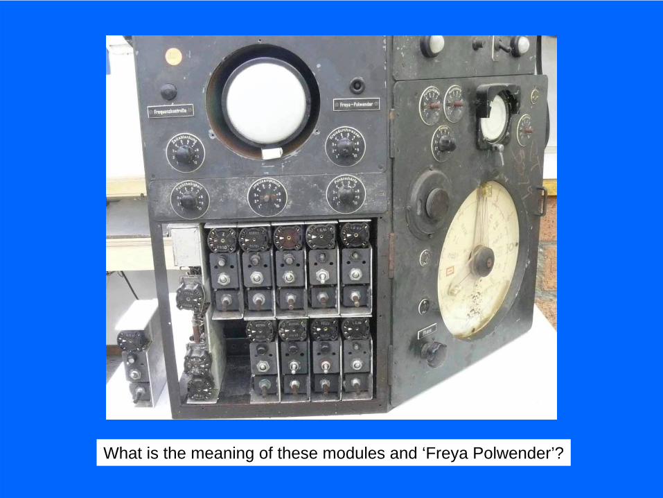
What is the meaning of these modules and ‘Freya Polwender’?
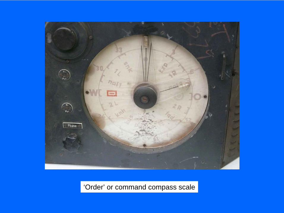
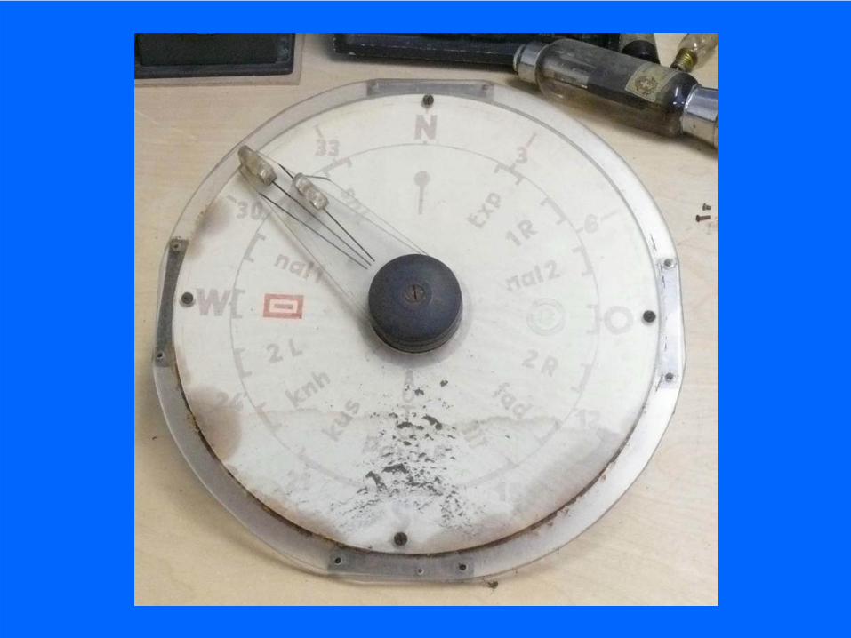
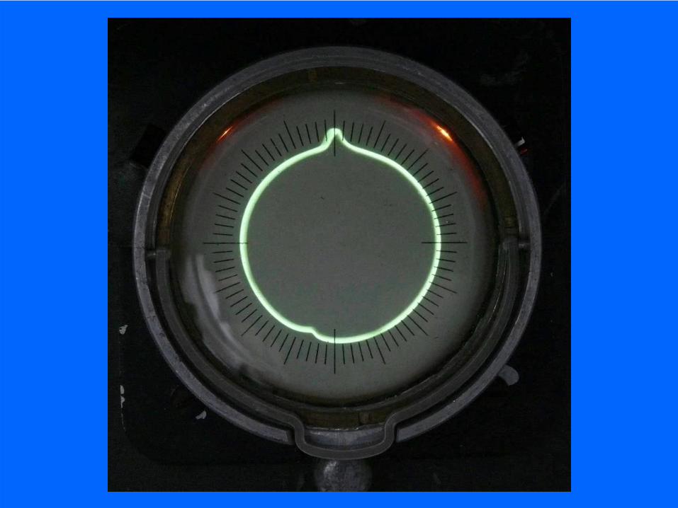
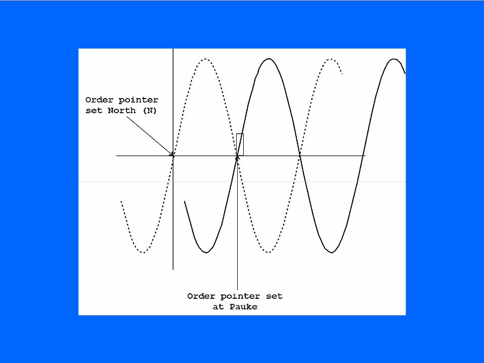
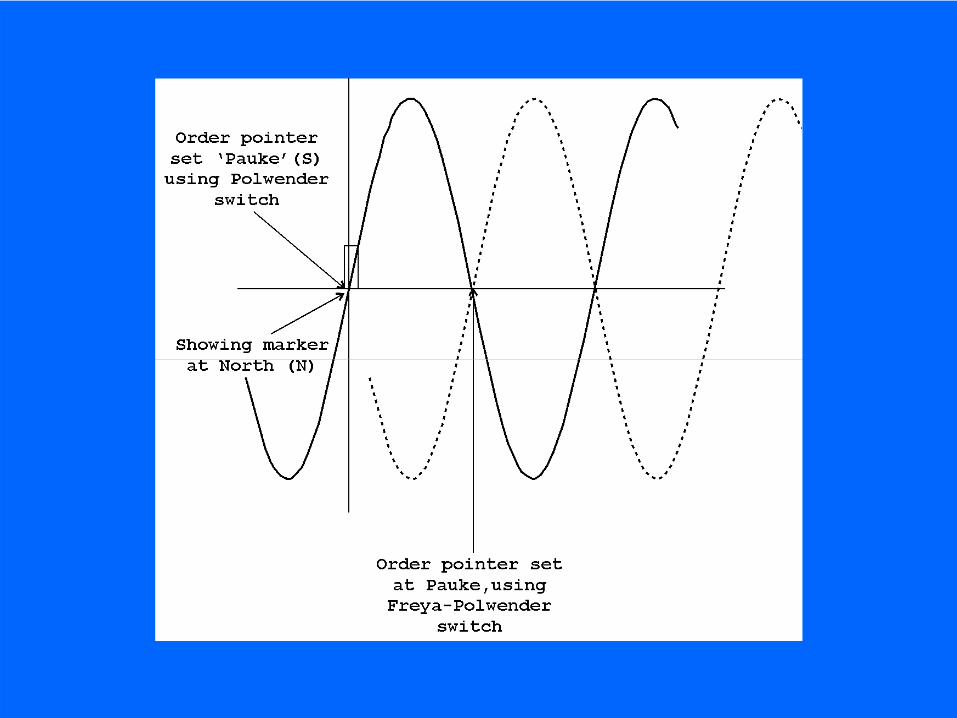
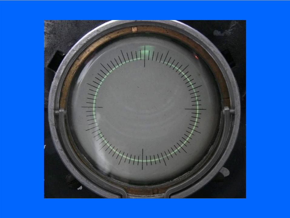
‘Order’ or command compass scale
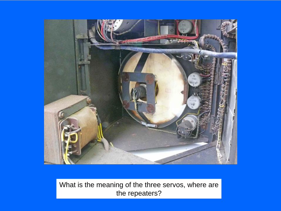
What is the meaning of the three servos, where arethe repeaters?
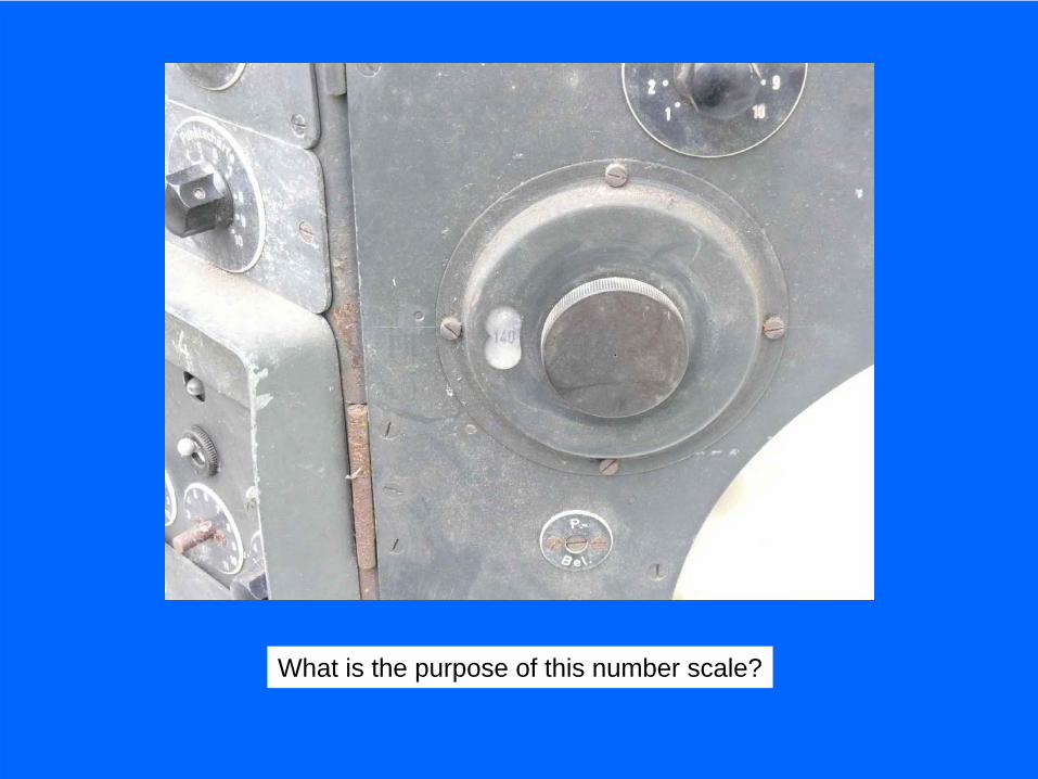
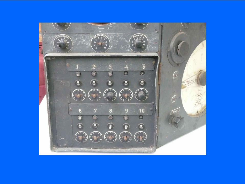
What is the purpose of this number scale?
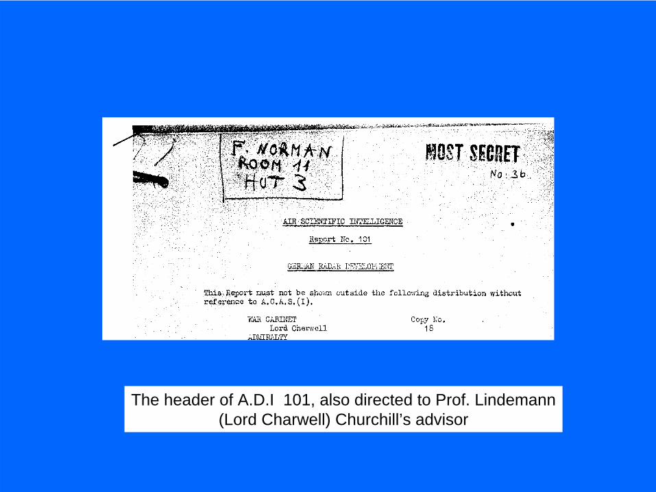
The header of A.D.I 101, also directed to Prof. Lindemann(Lord Charwell) Churchill’s advisor

What is behind the connectors?
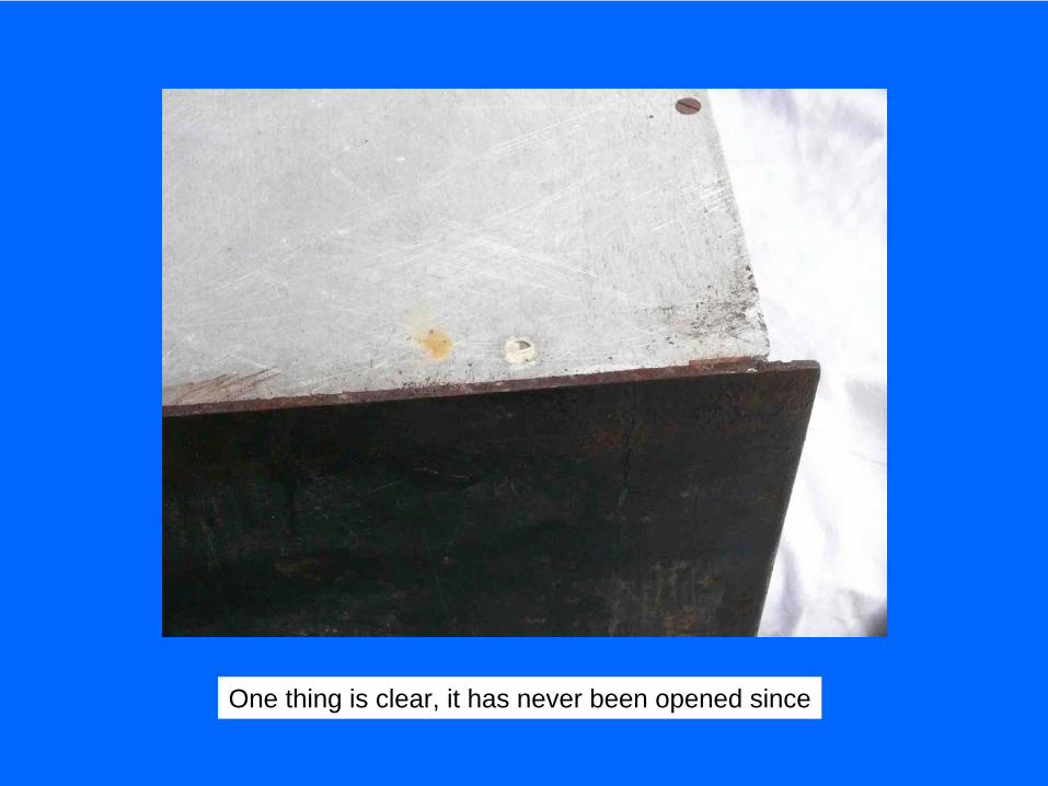
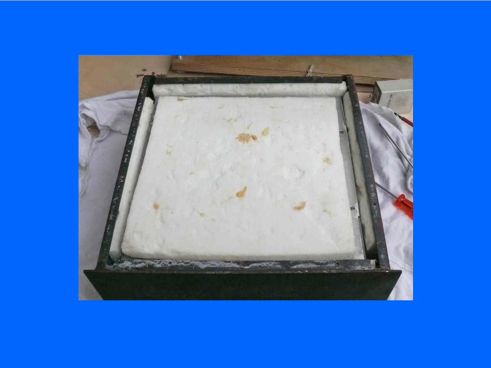
One thing is clear, it has never been opened since


What is the purpose of the two pointers?

The photo is proving that only the small ‘order’ or commandpointer is electrically linked onto the Nachtfee system
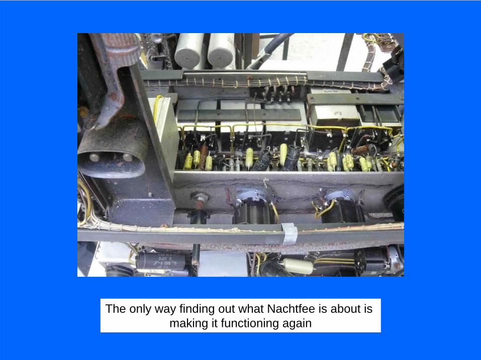
The only way finding out what Nachtfee is about is making it functioning again
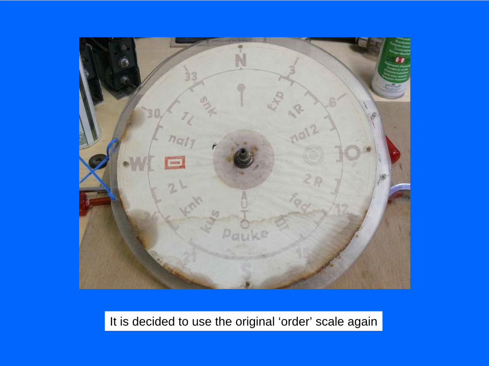
It is decided to use the original ‘order’ scale again
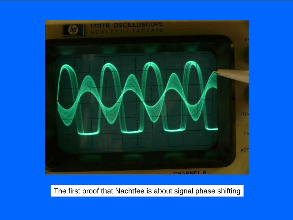
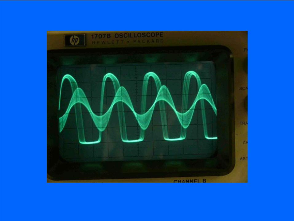
The first proof that Nachtfee is about signal phase shifting
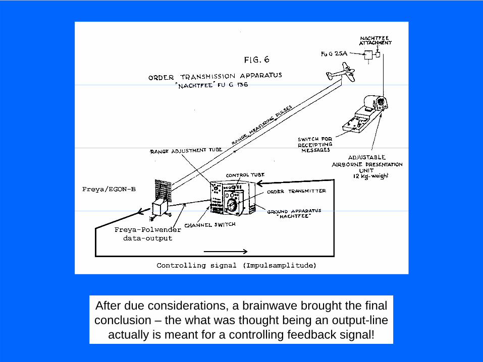
After due considerations, a brainwave brought the finalconclusion – the what was thought being an output-line
actually is meant for a controlling feedback signal!
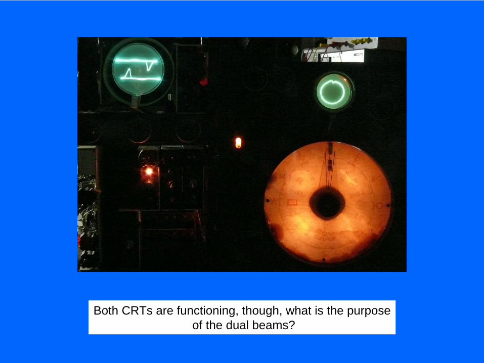
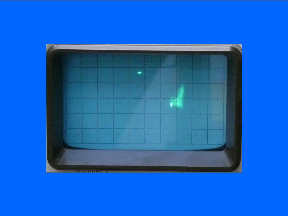
Both CRTs are functioning, though, what is the purposeof the dual beams?
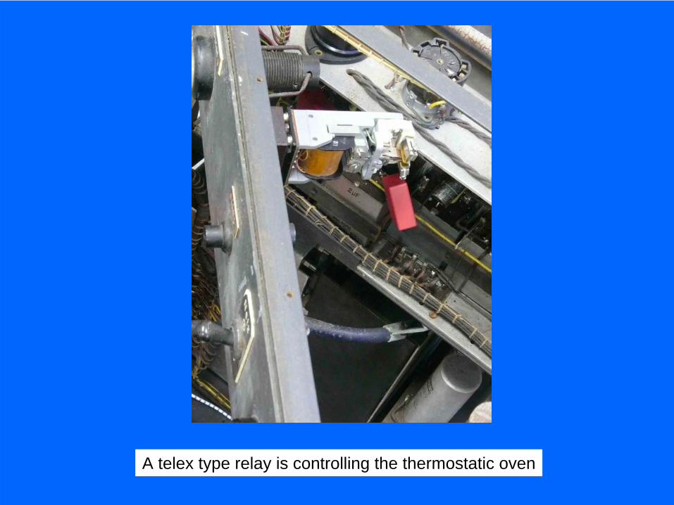
A telex type relay is controlling the thermostatic oven


Principle schematic of the 10 quartz controlled channelsincluding the two frequency dividers. Providing 4 Hz channel steps
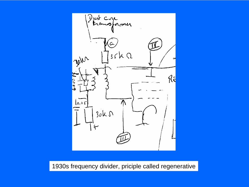
1930s frequency divider, priciple called regenerative

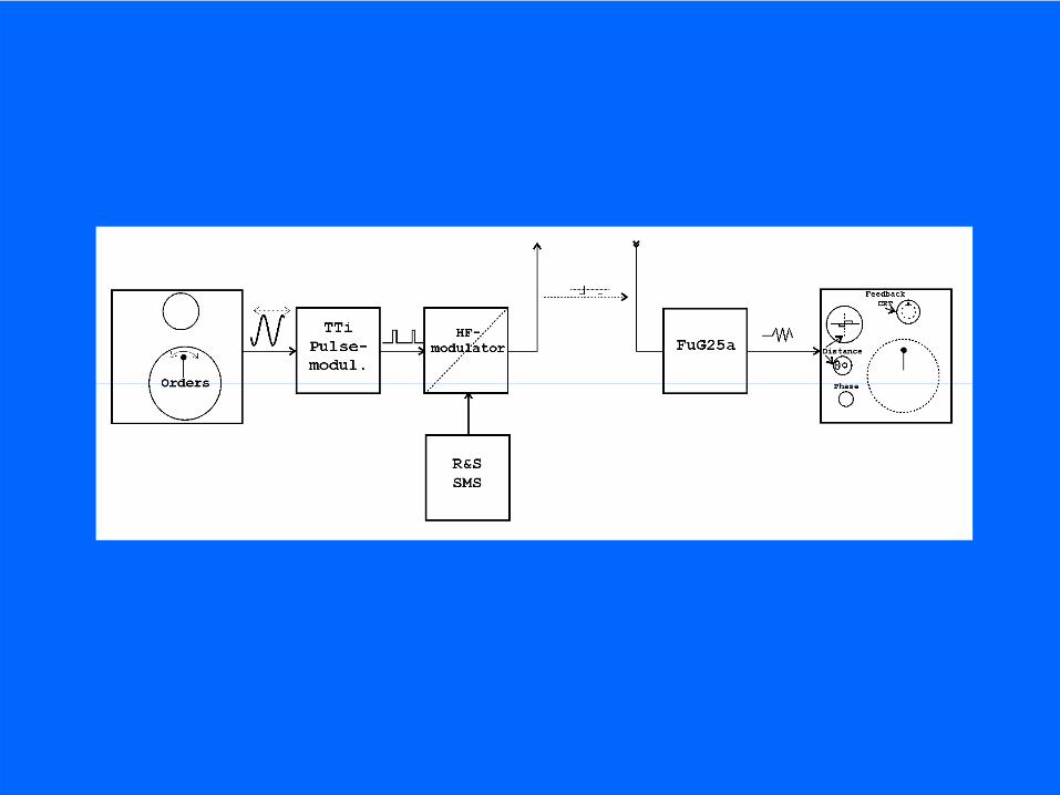
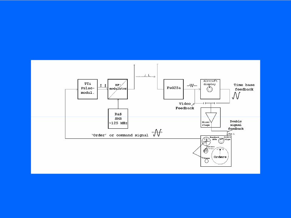
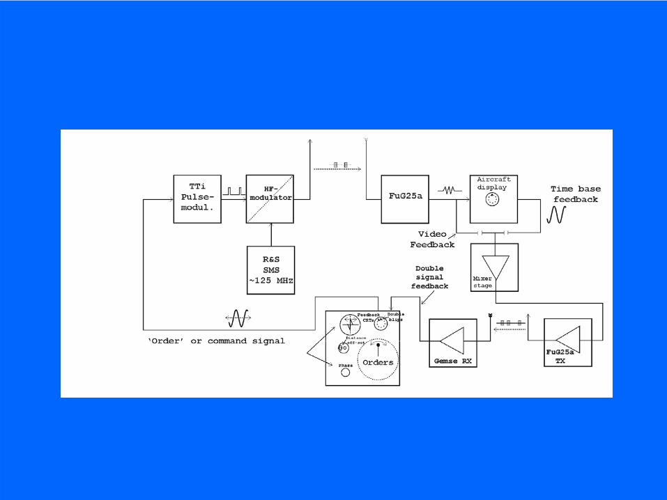
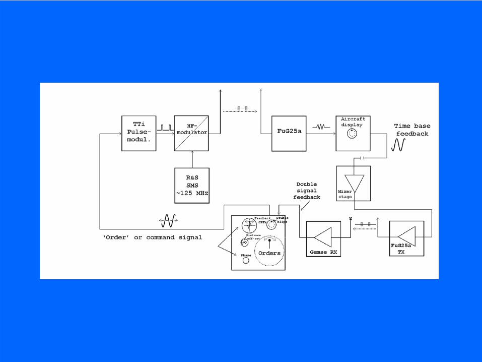
Block diagram of the Nachtfee apparatus
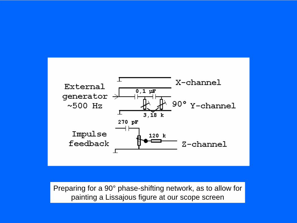
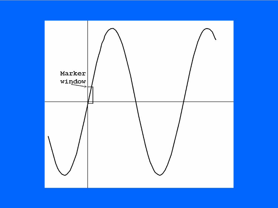
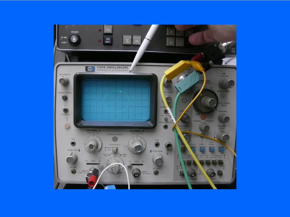
Preparing for a 90° phase-shifting network, as to allow forpainting a Lissajous figure at our scope screen
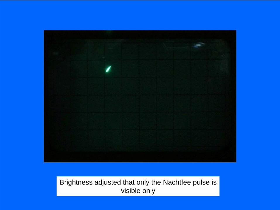
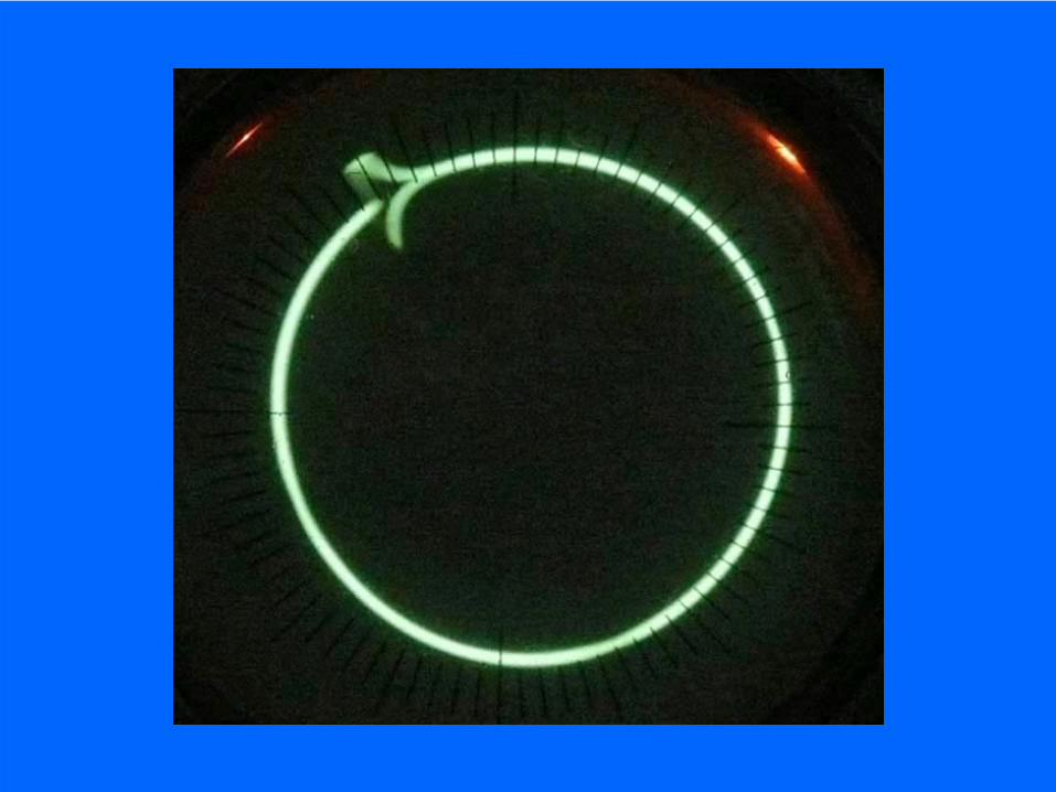
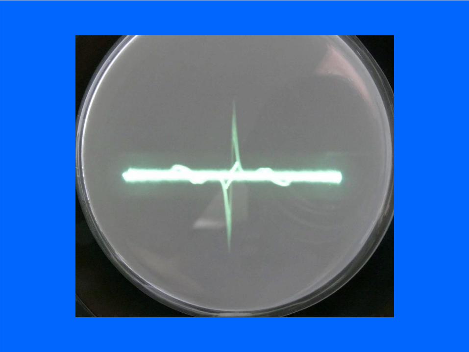
Brightness adjusted that only the Nachtfee pulse isvisible only

This setup is proving that even with steps of 0.01 Hz it is impossiblekeeping synchronism between the synthesizer and Nachtfee
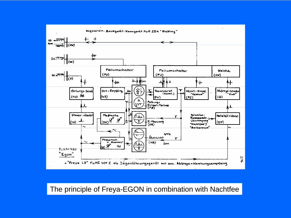
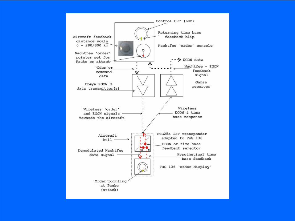
The principle of Freya-EGON in combination with Nachtfee

Distance or range off-set (compensation) scale
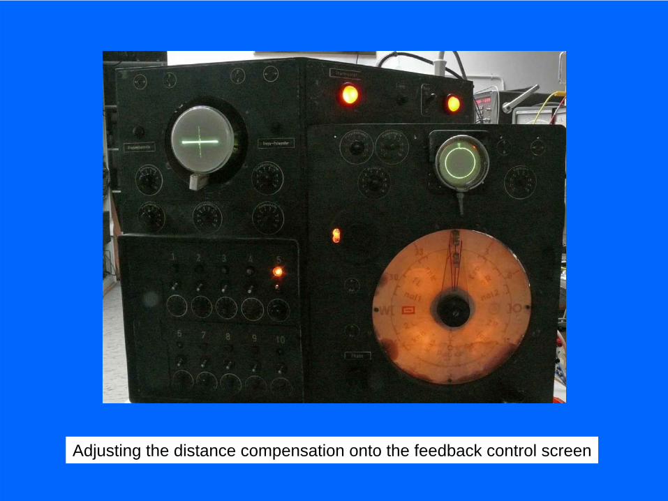
Adjusting the distance compensation onto the feedback control screen
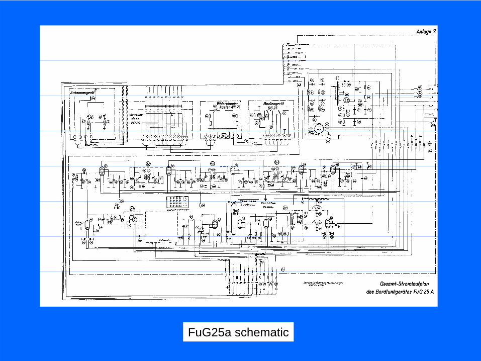
FuG25a schematic
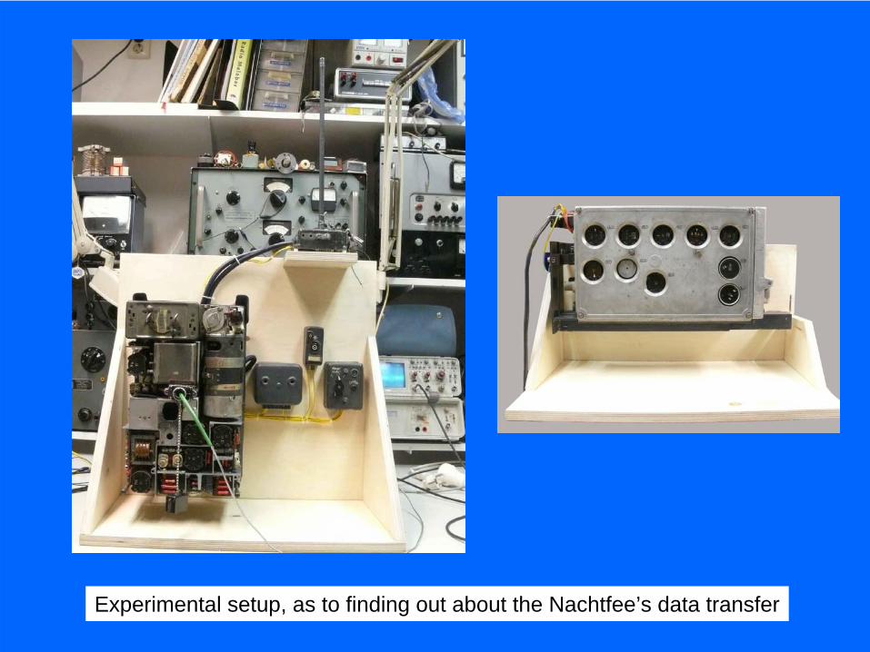
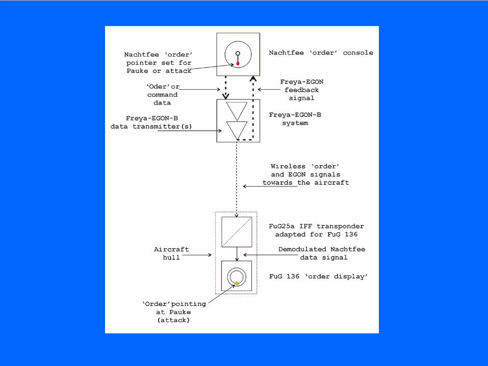
Experimental setup, as to finding out about the Nachtfee’s data transfer


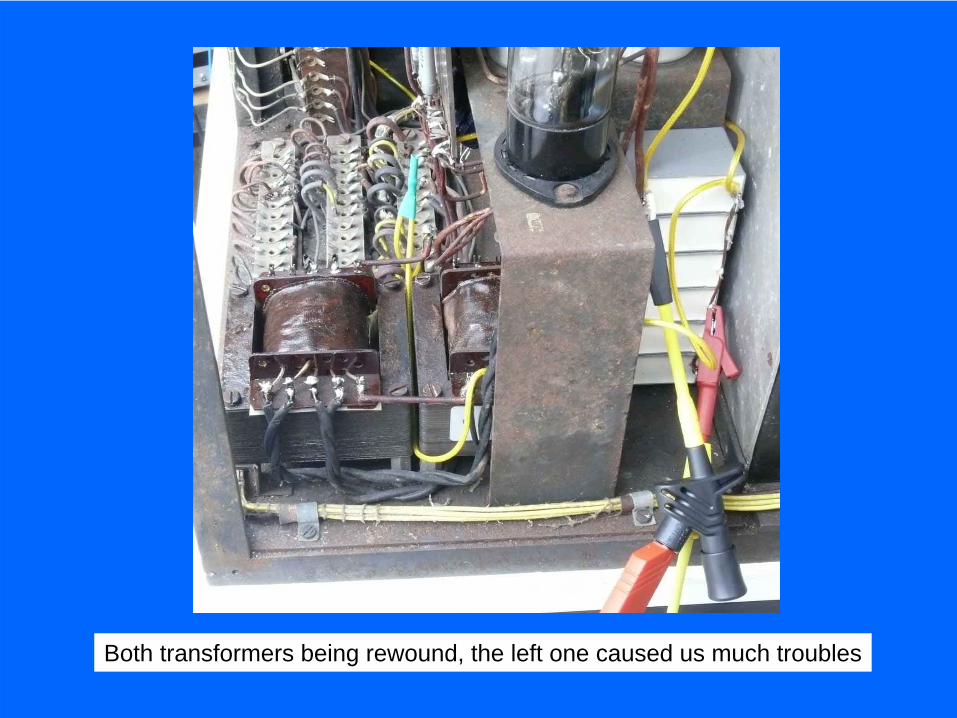
Both transformers being rewound, the left one caused us much troubles
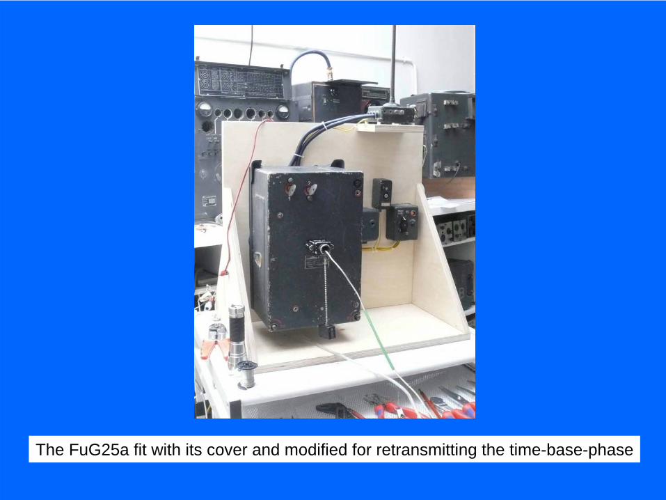
The FuG25a fit with its cover and modified for retransmitting the time-base-phase
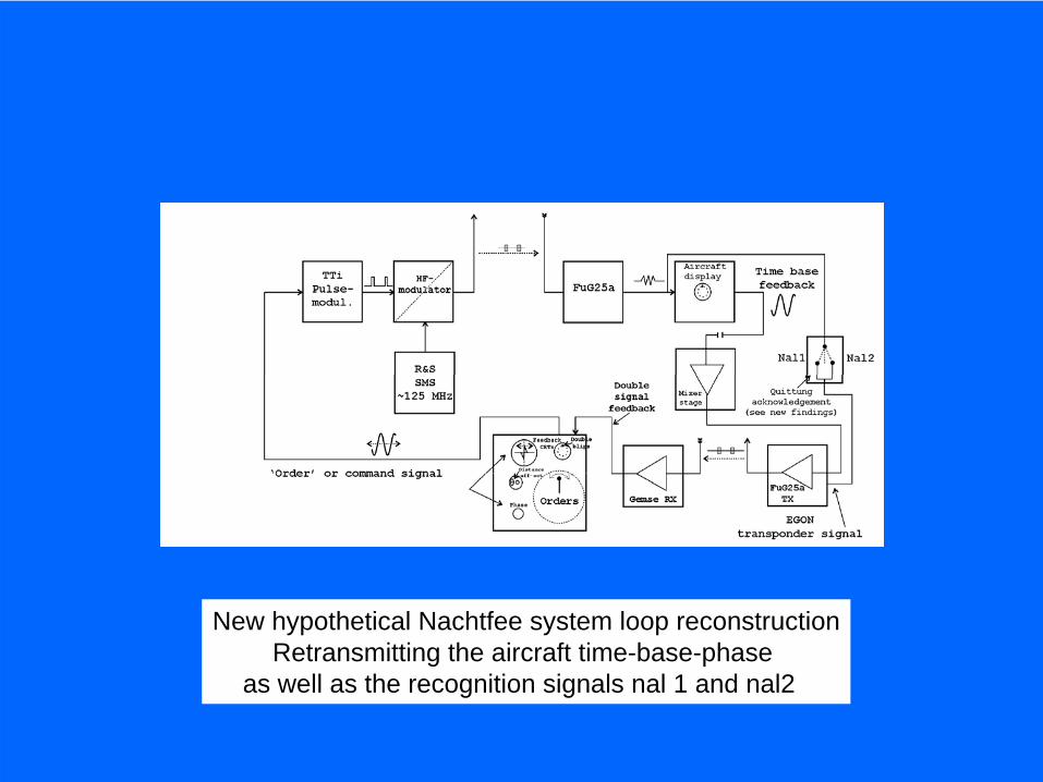
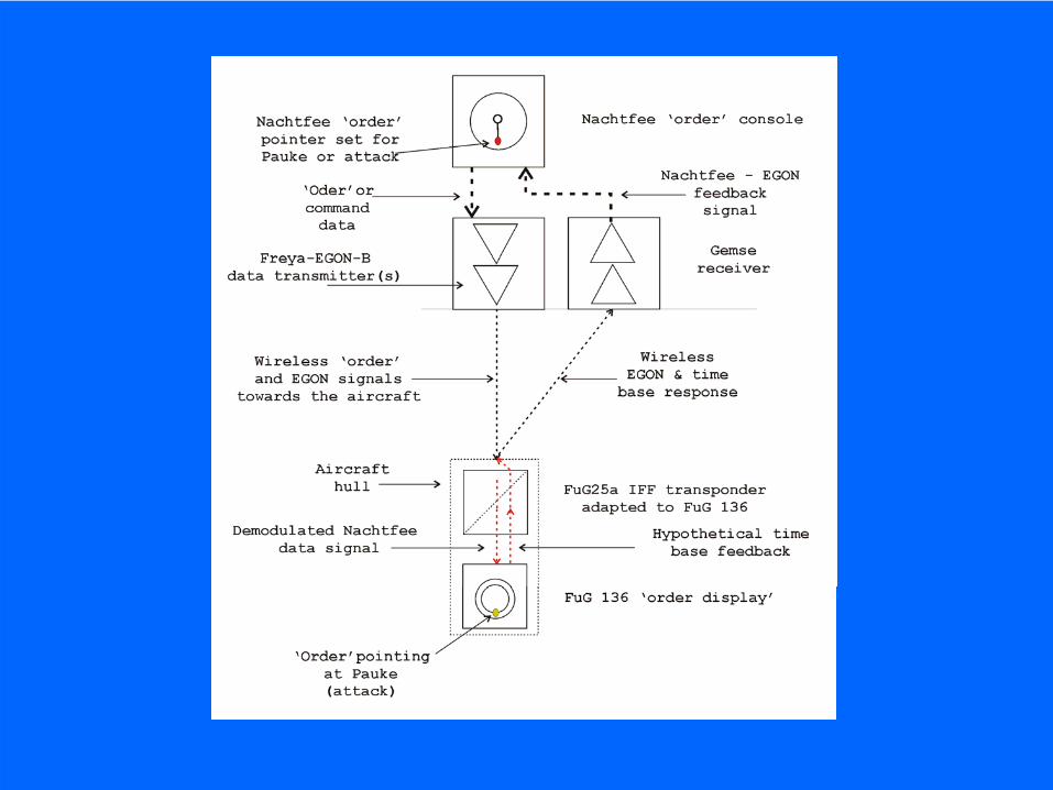
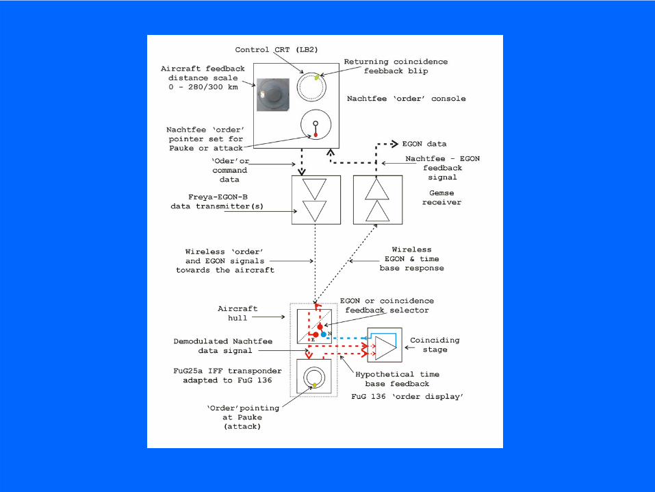
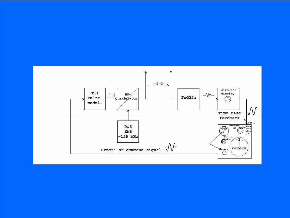
New hypothetical Nachtfee system loop reconstructionRetransmitting the aircraft time-base-phase
as well as the recognition signals nal 1 and nal2
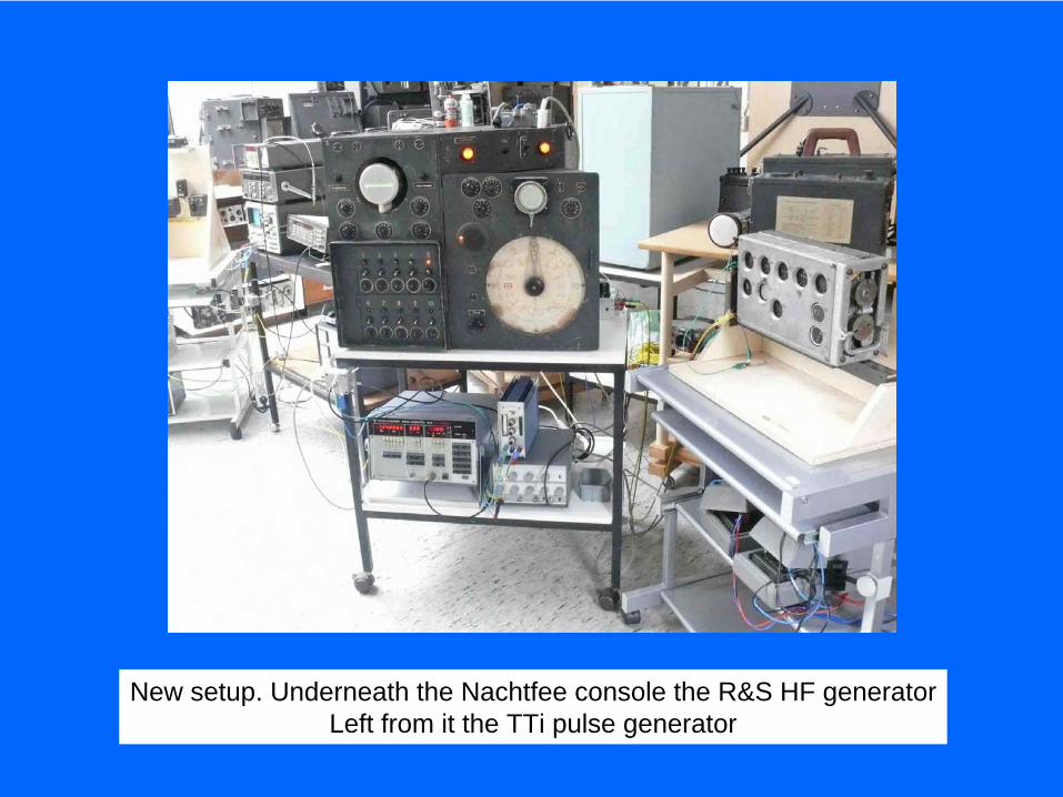
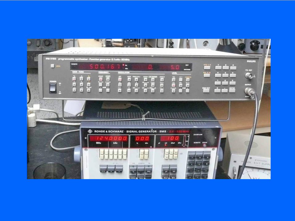
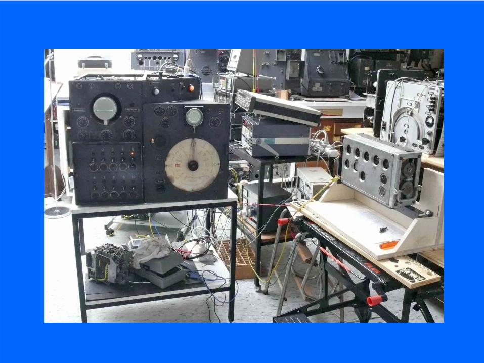
New setup. Underneath the Nachtfee console the R&S HF generatorLeft from it the TTi pulse generator
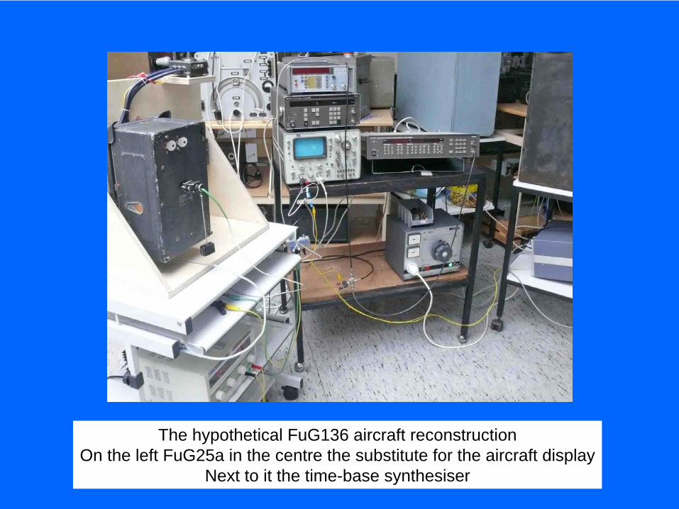
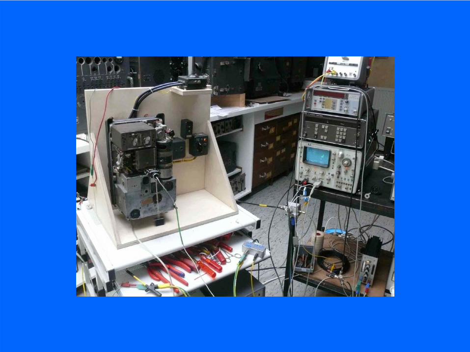
The hypothetical FuG136 aircraft reconstructionOn the left FuG25a in the centre the substitute for the aircraft display
Next to it the time-base synthesiser

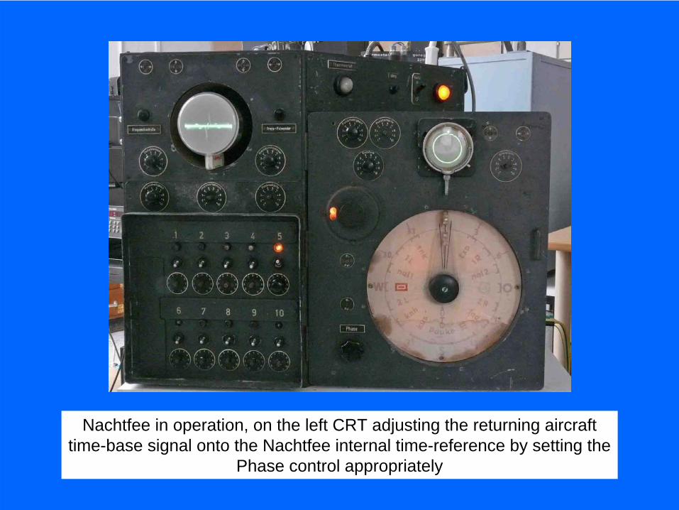
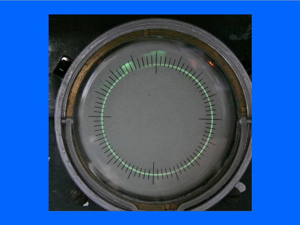
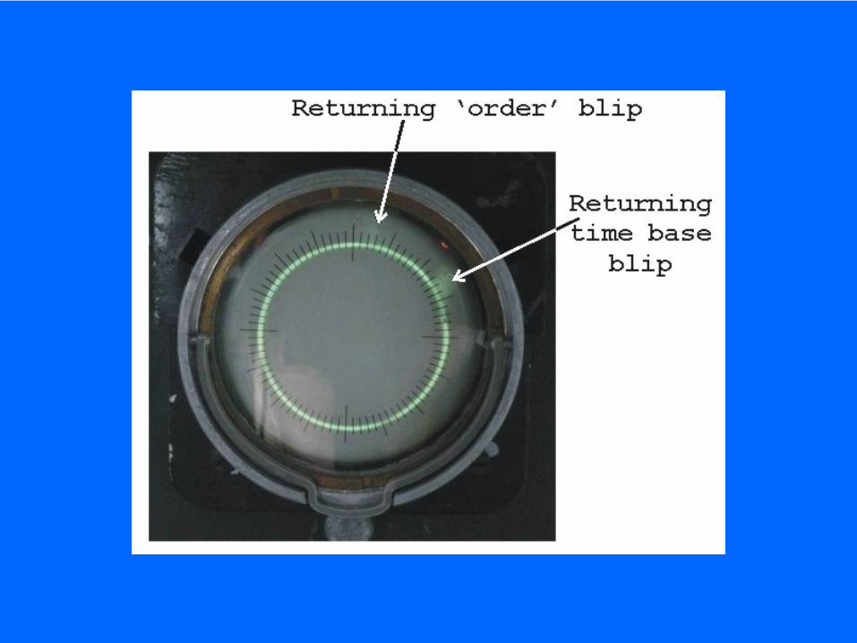
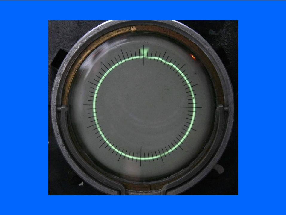
Nachtfee in operation, on the left CRT adjusting the returning aircrafttime-base signal onto the Nachtfee internal time-reference by setting the
Phase control appropriately
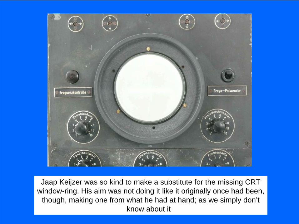
Jaap Keijzer was so kind to make a substitute for the missing CRTwindow-ring. His aim was not doing it like it originally once had been,
though, making one from what he had at hand; as we simply don’tknow about it
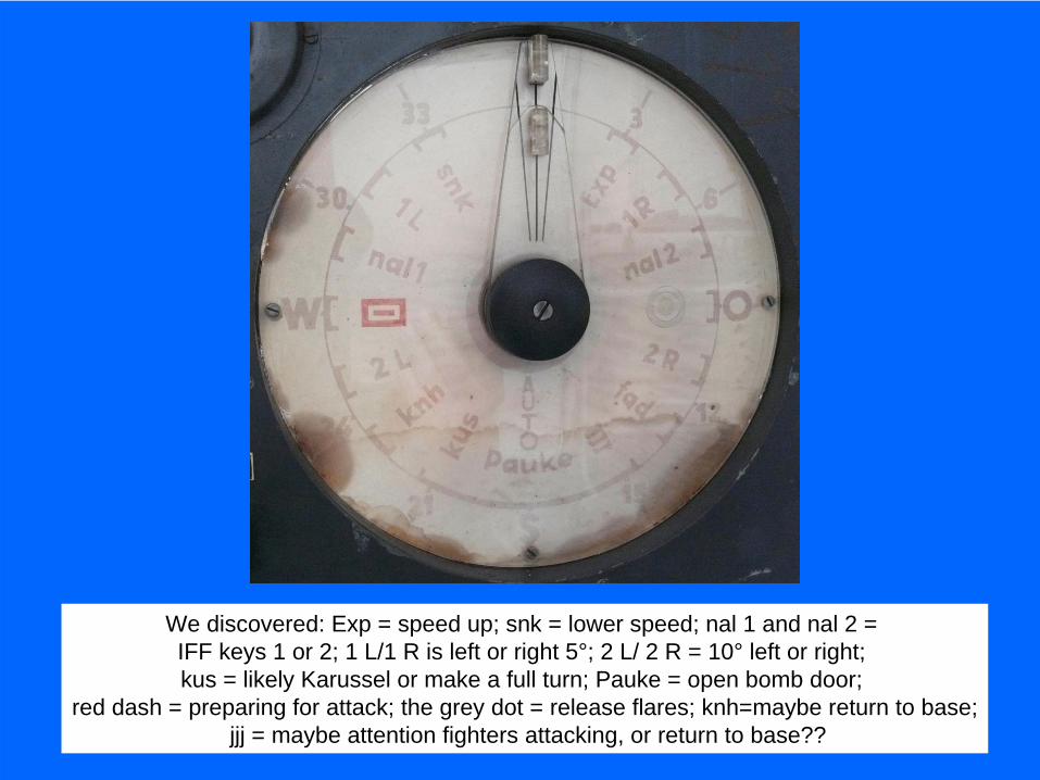
We discovered: Exp = speed up; snk = lower speed; nal 1 and nal 2 = IFF keys 1 or 2; 1 L/1 R is left or right 5°; 2 L/ 2 R = 10° left or right; kus = likely Karussel or make a full turn; Pauke = open bomb door;
red dash = preparing for attack; the grey dot = release flares; knh=maybe return to base;jjj = maybe attention fighters attacking, or return to base??
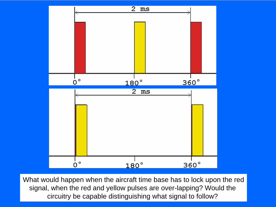
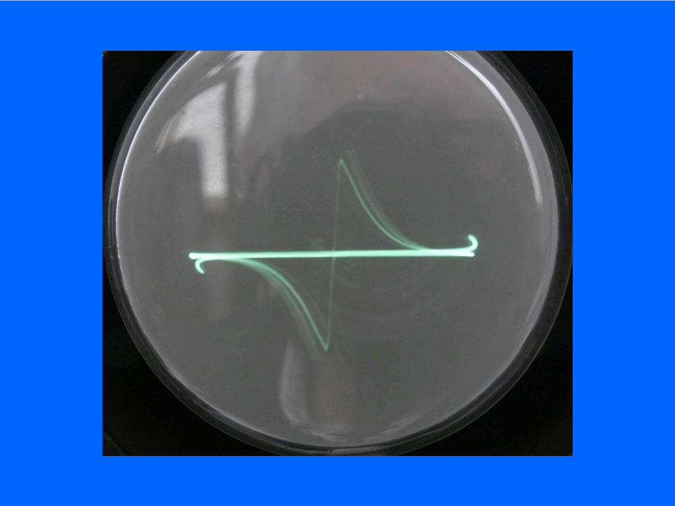
What would happen when the aircraft time base has to lock upon the redsignal, when the red and yellow pulses are over-lapping? Would the
circuitry be capable distinguishing what signal to follow?
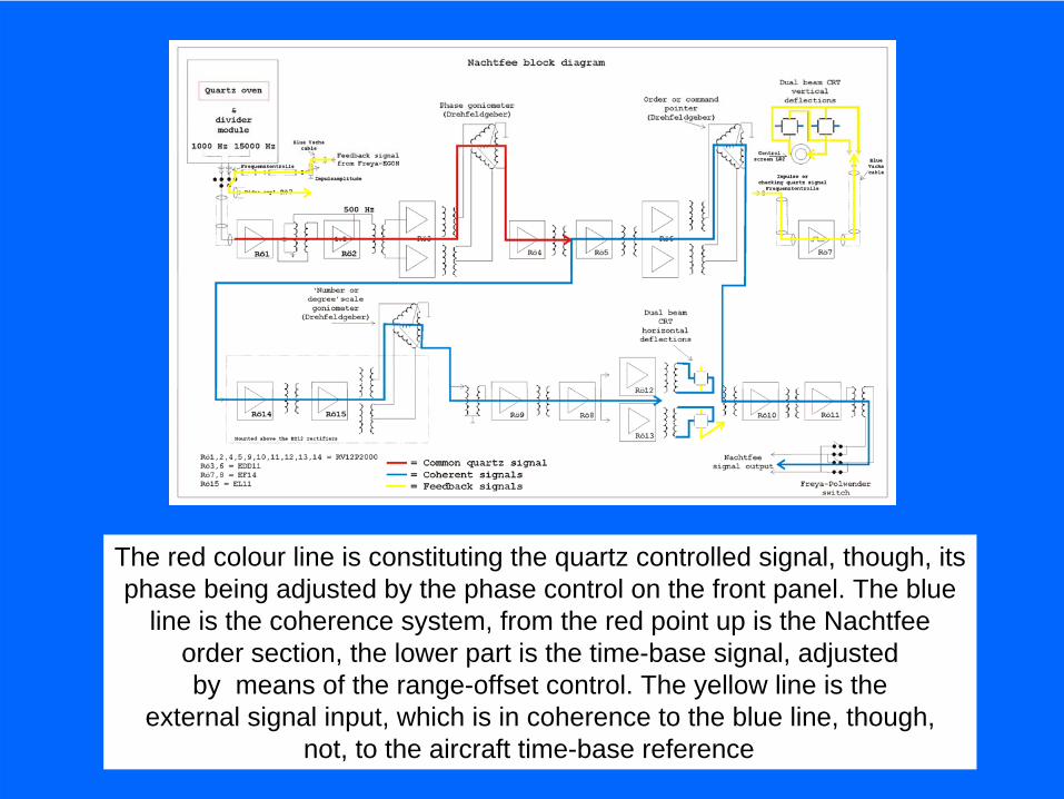
The red colour line is constituting the quartz controlled signal, though, itsphase being adjusted by the phase control on the front panel. The blue
line is the coherence system, from the red point up is the Nachtfeeorder section, the lower part is the time-base signal, adjustedby means of the range-offset control. The yellow line is the
external signal input, which is in coherence to the blue line, though,not, to the aircraft time-base reference
A new hypothetical system concept, we no longer operate at 500 Hzthough, we will operate at say 502 Hz. As to simulate the Freya-EGON pulseof 500 Hz, this signal has to be combined in the HF signal (dual pulses).
The concept of Freya-EGON according Fritz Trenkle

The schematic of the Nachtfee quartz oscillatorIt uses a quartz in serial mode
Quartz oscillator module. The potentiometer is, in contrast to what is thought,for adjusting the load of the quartz vibrator. Thus a negative feedback
The upper screen-shot shows medium quartz loading, the lower screenshows clear quartz over-loading. Q5 stopped within a minute operating
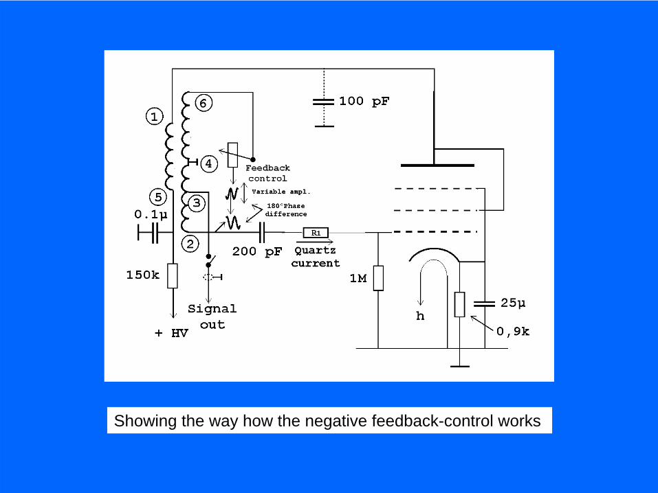
Showing the way how the negative feedback-control works
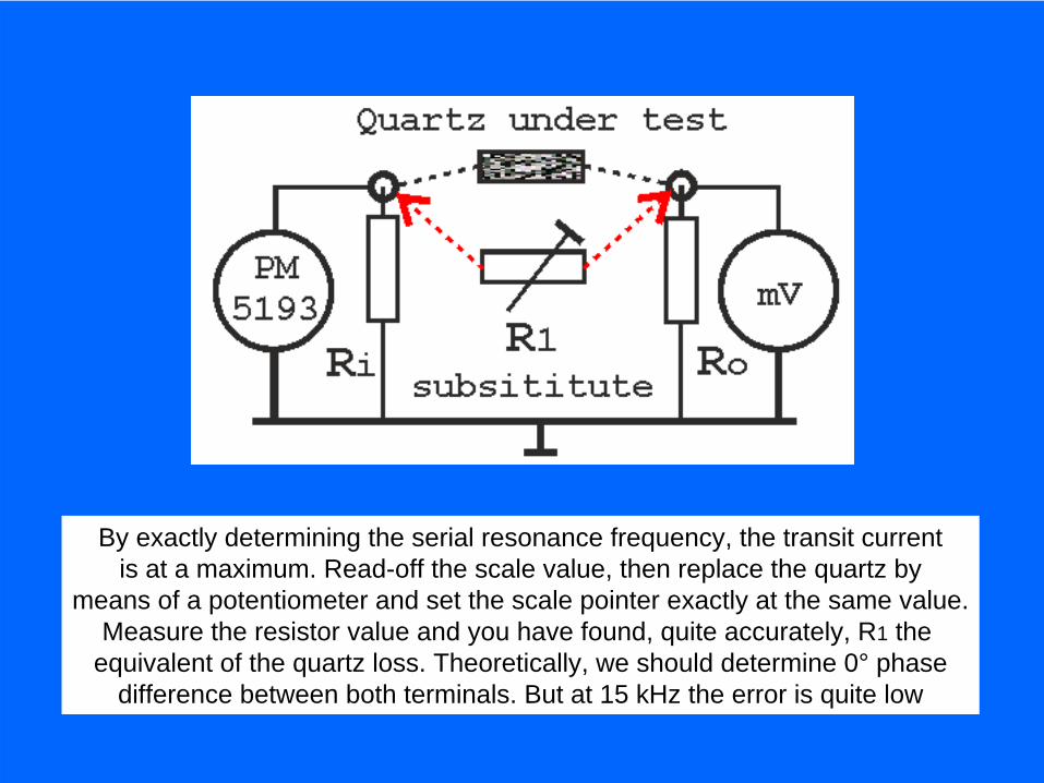
By exactly determining the serial resonance frequency, the transit currentis at a maximum. Read-off the scale value, then replace the quartz by
means of a potentiometer and set the scale pointer exactly at the same value.Measure the resistor value and you have found, quite accurately, R1 the
equivalent of the quartz loss. Theoretically, we should determine 0° phasedifference between both terminals. But at 15 kHz the error is quite low
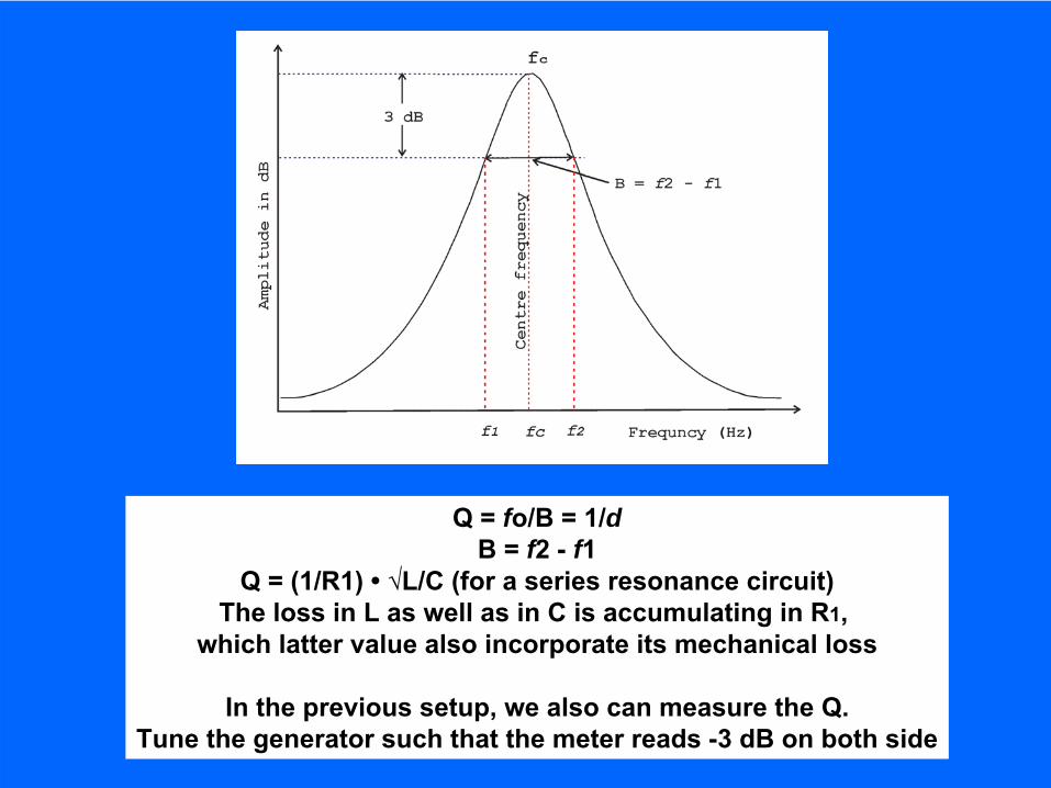
Q = fo/B = 1/dB = f2 -
f1
Q = (1/R1) •
√L/C (for a series resonance circuit)The loss in L as well as in C is accumulating in R1,
which latter value also incorporate its mechanical loss
In the previous setup, we also can measure the Q.Tune the generator such that the meter reads -3 dB on both side