Nabertherm Advanced Materials - Airtemp · chamber furnace, SiC, HTC .., page 50 High-temperature...
72
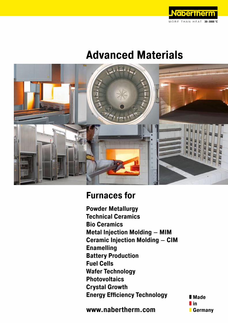
www.nabertherm.com Advanced Materials Furnaces for Powder Metallurgy Technical Ceramics Bio Ceramics Metal Injection Molding – MIM Ceramic Injection Molding – CIM Enamelling Battery Production Fuel Cells Wafer Technology Photovoltaics Crystal Growth Energy Efficiency Technology Made in Germany
Transcript of Nabertherm Advanced Materials - Airtemp · chamber furnace, SiC, HTC .., page 50 High-temperature...
www.nabertherm.com
Advanced Materials
Furnaces forPowder MetallurgyTechnical CeramicsBio CeramicsMetal Injection Molding – MIMCeramic Injection Molding – CIMEnamellingBattery ProductionFuel CellsWafer TechnologyPhotovoltaicsCrystal GrowthEnergy Efficiency Technology Made
inGermany
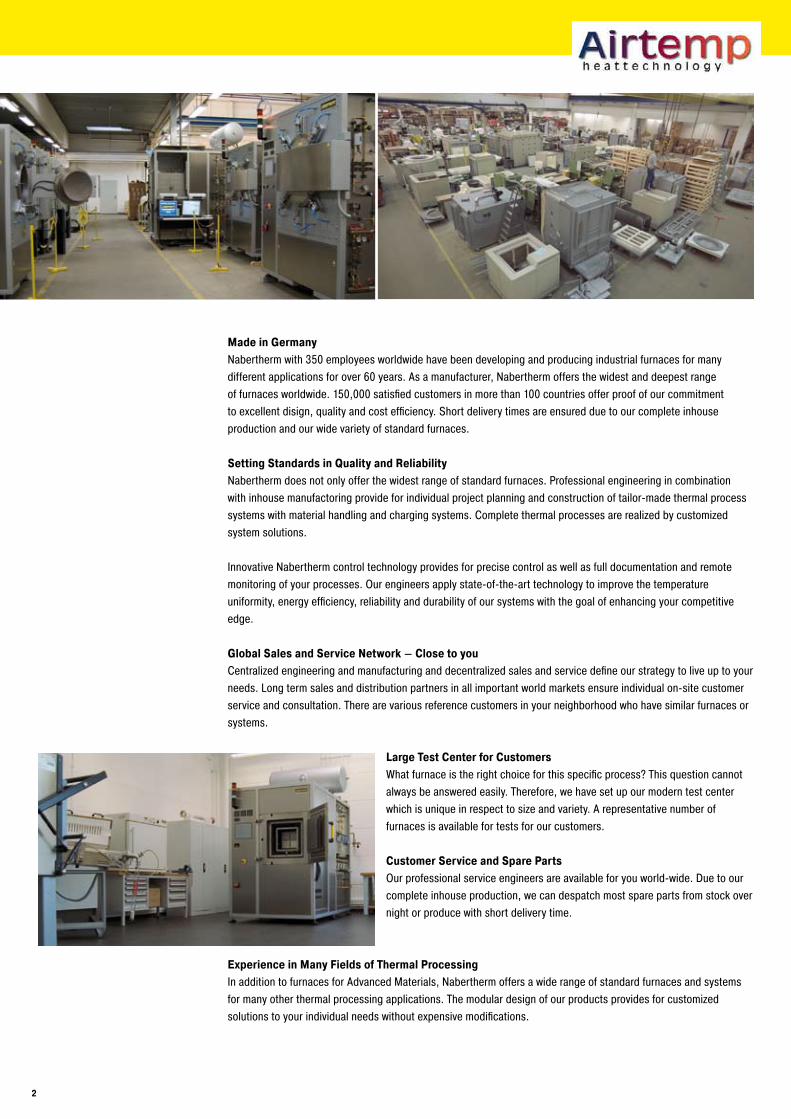
Made in GermanyNabertherm with 350 employees worldwide have been developing and producing industrial furnaces for many different applications for over 60 years. As a manufacturer, Nabertherm offers the widest and deepest range of furnaces worldwide. 150,000 satisfied customers in more than 100 countries offer proof of our commitment to excellent disign, quality and cost efficiency. Short delivery times are ensured due to our complete inhouse production and our wide variety of standard furnaces.
Setting Standards in Quality and ReliabilityNabertherm does not only offer the widest range of standard furnaces. Professional engineering in combination with inhouse manufactoring provide for individual project planning and construction of tailor-made thermal process systems with material handling and charging systems. Complete thermal processes are realized by customized system solutions.
Innovative Nabertherm control technology provides for precise control as well as full documentation and remote monitoring of your processes. Our engineers apply state-of-the-art technology to improve the temperature uniformity, energy efficiency, reliability and durability of our systems with the goal of enhancing your competitive edge.
Global Sales and Service Network – Close to youCentralized engineering and manufacturing and decentralized sales and service define our strategy to live up to your needs. Long term sales and distribution partners in all important world markets ensure individual on-site customer service and consultation. There are various reference customers in your neighborhood who have similar furnaces or systems.
Large Test Center for CustomersWhat furnace is the right choice for this specific process? This question cannot always be answered easily. Therefore, we have set up our modern test center which is unique in respect to size and variety. A representative number of furnaces is available for tests for our customers.
Customer Service and Spare PartsOur professional service engineers are available for you world-wide. Due to our complete inhouse production, we can despatch most spare parts from stock over night or produce with short delivery time.
Experience in Many Fields of Thermal ProcessingIn addition to furnaces for Advanced Materials, Nabertherm offers a wide range of standard furnaces and systems for many other thermal processing applications. The modular design of our products provides for customized solutions to your individual needs without expensive modifications.
�
Content Page
Which Furnace for Which Process? ....................................................................................................... 4
Matrix Debinding Technology ............................................................................................................... 6
Heat Recovery Systems for Energy Savings Purposes .......................................................................... 7
Air Circulation FurnacesAir circulation chamber furnaces for debinding in air up to 650 °C ................................................................. 8Air circulation bogie hearth furnaces for debinding in air up to 600 °C ........................................................... 9Air circulation chamber furnaces/ovens with safety technology for solvent-containing charges according to EN 1539 or NFPA 86 ........................................................................................................10Ovens up to 300 °C ..............................................................................................................................11
Dewaxing Furnaces, Electrically Heated or Gas-Fired .........................................................................12
Furnaces with Radiation Heating up to 1400 °CBogie hearth furnaces, also as combi furnaces for debinding and sintering in one process ..............................14Pit-type and top-loading furnaces ...........................................................................................................17Lift-top or lift-bottom furnaces, also as combi furnaces for debinding and sintering in one process ................. 18Combi chamber furnaces for debinding and sintering in one process .......................................................... 20Chamber furnaces ............................................................................................................................... 22
Gas-fired Chamber Furnaces up to 1400 °CGas-fired chamber furnaces, also as combi furnaces for debinding and sintering in one process ..................... 24Gas-fired bogie hearth furnaces for firing or sintering or as combi furnace for debinding and sintering in one process.. ......................................................................................... 25
High-Temperature Furnaces up to 1800 °CLift-top and lift-bottom furnaces ............................................................................................................ 26Chamber furnaces with fiber insulation ................................................................................................... 30Chamber furnaces with lightweight refractory brick insulation .................................................................... 33Gas-fired Chamber furnaces ................................................................................................................. 34
Catalytic and Thermal Afterburning Systems ...................................................................................... 35
Furnaces for continuous ProcessesRotary hearth furnaces up to 1300 °C, electrically heated or gas-fired ......................................................... 36Continuous furnaces .............................................................................................................................37
Retort Furnaces up to 1100 °C resp. �400 °CChamber retort furnaces ...................................................................................................................... 38Chamber and bogie hearth furnaces with gas box for debinding under protective gases ................................. 40Pit-type retort furnaces .........................................................................................................................41High-temperature chamber retort furnaces .............................................................................................. 42Chamber retort ovens for catalytic debinding .......................................................................................... 46
Laboratory FurnacesFast-firing furnaces ..............................................................................................................................47Gradient or lab strand annealing furnaces ................................................................................................47Professional chamber furnaces with brick or fibre insulation ...................................................................... 48High-temperature furnaces with SiC rod heating ...................................................................................... 50High-temperature furnaces with MoSi2 heating elements as table-top model ................................................51High-temperature lift-bottom furnaces without or with retort ..................................................................... 52High-temperature furnace with scale for determination of combustion loss and thermographical analysis (TGA) .... 53
Tube Furnaces up to 1800 °C .............................................................................................................. 54
Process Control and Documentation .................................................................................................. 70�
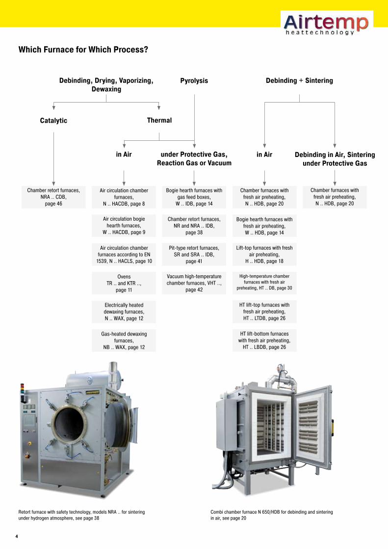
Which Furnace for Which Process?
Debinding, Drying, Vaporizing, Dewaxing
Bogie hearth furnaces with gas feed boxes,
W .. IDB, page 14
Chamber retort furnaces,NRA .. CDB,
page 46
Air circulation bogie hearth furnaces,
W .. HACDB, page 9
Vacuum high-temperature chamber furnaces, VHT ..,
page 42
Pit-type retort furnaces,SR and SRA .. IDB,
page 41
Chamber retort furnaces,NR and NRA .. IDB,
page 38
Air circulation chamber furnaces,
N .. HACDB, page 8
HT lift-bottom furnaces with fresh air preheating,
HT .. LBDB, page 26
HT lift-top furnaces with fresh air preheating,HT .. LTDB, page 26
High-temperature chamber furnaces with fresh air
preheating, HT .. DB, page 30
Lift-top furnaces with fresh air preheating,
H .. HDB, page 18
Bogie hearth furnaces with fresh air preheating,W .. HDB, page 14
Chamber furnaces with fresh air preheating,N .. HDB, page 20
Chamber furnaces with fresh air preheating,N .. HDB, page 20
Catalytic
in Air under Protective Gas, Reaction Gas or Vacuum
Thermal
in Air Debinding in Air, Sintering under Protective Gas
Debinding + SinteringPyrolysis
Gas-heated dewaxing furnaces,
NB .. WAX, page 12
Electrically heated dewaxing furnaces,N .. WAX, page 12
OvensTR .. and KTR ..,
page 11
Air circulation chamber furnaces according to EN
1539, N .. HACLS, page 10
Retort furnace with safety technology, models NRA .. for sintering under hydrogen atmosphere, see page 38
Combi chamber furnace N 650/HDB for debinding and sintering in air, see page 20
4
Lift-top and lift-bottom furnaces,
H .., page 18
Bogie hearth furnaces,W ..,
page 14
Chamber furnaces,N ..,
page 22
Pit-type retort furnaces,SR .. and SRA,
page 41
Chamber retort furnaces,NR .. and NRA ..,
page 40
Sealed high-temperature furnaces,
HT .., page 30
Sealed lift-top and lift-bottom furnaces,
H .., page 18
Bogie hearth furnaces with gas boxes,
W .., page 14
Sealed chamber furnaces,N ..,
page 22
Rotary hearth furnaces,DH ..,
page 36
Continuous furnace,D ..,
page 37
High-temperature chamber furnaces, gas-heated,
HTB .., page 34
High-temperature chamber furnaces, stone-insulated,
HFL .., page 33
High-temperature lift-top furnaces,
HT ..LT, page 26
High-temperature lift-bottom furnaces,
HT .. LB, page 26
High-temperature chamber furnaces,
HT .., page 30
Gas-heated bogie hearth furnaces,
WB .., page 25
Gas-heated chamber furnaces,
NB .., page 24
Pit-type and chest furnaces,
S .., page 17
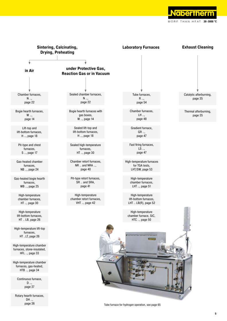
Exhaust CleaningLaboratory FurnacesSintering, Calcinating,Drying, Preheating
under Protective Gas, Reaction Gas or in Vacuum
in Air
High-temperature chamber furnace, SiC,
HTC .., page 50
High-temperature lift-bottom furnaces,
LHT .. LB(R), page 52
High-temperature chamber furnaces,
LHT .., page 51
High-temperature furnaces for TGA tests,
LHT/SW, page 53
Fast firing furnaces,LS ..,
page 47
Gradient furnace,GR ..,
page 47
Chamber furnaces,LH ..,
page 48
Tube furnaces,R ..,
page 54
High-temperature chamber retort furnaces,
VHT .., page 42
Catalytic afterburning,page 35
Thermal afterburning,page 35
Tube furnace for hydrogen operation, see page 65
�
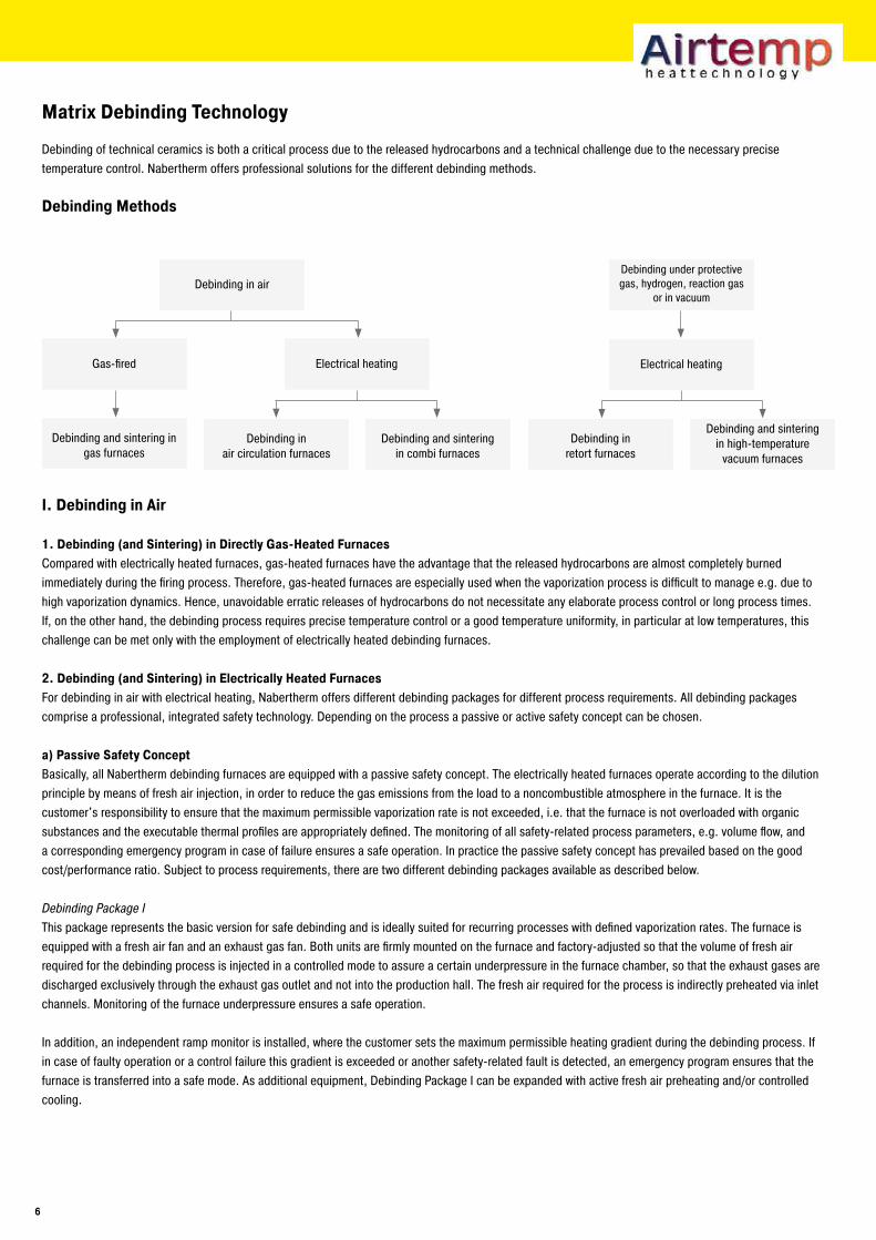
Matrix Debinding Technology
Debinding of technical ceramics is both a critical process due to the released hydrocarbons and a technical challenge due to the necessary precise temperature control. Nabertherm offers professional solutions for the different debinding methods.
Debinding Methods
I. Debinding in Air
1. Debinding (and Sintering) in Directly Gas-Heated FurnacesCompared with electrically heated furnaces, gas-heated furnaces have the advantage that the released hydrocarbons are almost completely burned immediately during the firing process. Therefore, gas-heated furnaces are especially used when the vaporization process is difficult to manage e.g. due to high vaporization dynamics. Hence, unavoidable erratic releases of hydrocarbons do not necessitate any elaborate process control or long process times. If, on the other hand, the debinding process requires precise temperature control or a good temperature uniformity, in particular at low temperatures, this challenge can be met only with the employment of electrically heated debinding furnaces.
�. Debinding (and Sintering) in Electrically Heated FurnacesFor debinding in air with electrical heating, Nabertherm offers different debinding packages for different process requirements. All debinding packages comprise a professional, integrated safety technology. Depending on the process a passive or active safety concept can be chosen.
a) Passive Safety ConceptBasically, all Nabertherm debinding furnaces are equipped with a passive safety concept. The electrically heated furnaces operate according to the dilution principle by means of fresh air injection, in order to reduce the gas emissions from the load to a noncombustible atmosphere in the furnace. It is the customer's responsibility to ensure that the maximum permissible vaporization rate is not exceeded, i.e. that the furnace is not overloaded with organic substances and the executable thermal profiles are appropriately defined. The monitoring of all safety-related process parameters, e.g. volume flow, and a corresponding emergency program in case of failure ensures a safe operation. In practice the passive safety concept has prevailed based on the good cost/performance ratio. Subject to process requirements, there are two different debinding packages available as described below.
Debinding Package IThis package represents the basic version for safe debinding and is ideally suited for recurring processes with defined vaporization rates. The furnace is equipped with a fresh air fan and an exhaust gas fan. Both units are firmly mounted on the furnace and factory-adjusted so that the volume of fresh air required for the debinding process is injected in a controlled mode to assure a certain underpressure in the furnace chamber, so that the exhaust gases are discharged exclusively through the exhaust gas outlet and not into the production hall. The fresh air required for the process is indirectly preheated via inlet channels. Monitoring of the furnace underpressure ensures a safe operation.
In addition, an independent ramp monitor is installed, where the customer sets the maximum permissible heating gradient during the debinding process. If in case of faulty operation or a control failure this gradient is exceeded or another safety-related fault is detected, an emergency program ensures that the furnace is transferred into a safe mode. As additional equipment, Debinding Package I can be expanded with active fresh air preheating and/or controlled cooling.
Debinding and sinteringin combi furnaces
Debinding in air circulation furnaces
Debinding and sintering in gas furnaces
Electrical heatingGas-fired
Debinding in air
Debinding in retort furnaces
Debinding and sinteringin high-temperature
vacuum furnaces
Electrical heating
Debinding under protective gas, hydrogen, reaction gas
or in vacuum
�
Debinding Package IIDebinding Package II is the convenient solution for the variable ceramics production, since there is ample flexibility to accommodate different or frequently changing debinding processes. The basic differences and advantages compared with Debinding Package I are:
Program adjustable fresh air volume depending on the vaporization rate of the productFresh air preheating with separate air preheater. The fresh air temperature (up to max. 500 °C) is controlled as additional heat source depending on the furnace temperature. This results in a very good heat transfer and improved temperature uniformity.Automatic control of the exhaust gas fan depending on the preselected fresh air volume provides for advantages in temperature control (temperature uniformity) and adapted discharge of the exhaust gasesDifferentiated emergency program: Depending on the fault different emergency programs are automatically executedPerforated injection tubes in the furnace chamber depening on furnace model for uniform distribution of the preheated fresh air through the horizontal charging layers Display at the furnace for underpressure and volume flowPLC controls with touch panel H 1700 (see also page 70)Controlled cooling as standard
b) Active Safety ConceptAlternatively, an active safety concept is also available as additional equipment on request. The actually vaporized organic volume in the furnace chamber is monitored by means of the flame-thermal analysis (FTA). The fresh air and exhaust gas fans are automatically reconciled accordingly. In case of unsafe condition in the furnace e.g. from overloading, a heating gradient that is too fast or inadequate fresh air supply, the necessary emergency program is immediately initiated depending on the process step.
�.1. Debinding in Air Circulation FurnacesAir circulation furnaces are generally the right choice when debinding is the only process. Depending on the raw materials or temperature requirements, the green compacts can also be presintered. Air circulation furnaces convince by their good temperature uniformity even with dense loads, their accelerated heat transfer and their better charge penetration. Debinding and sintering in two process steps is always advisable if a better capacity utilization of the different furnaces and a reduced overall investment volume can be achieved.
�.�. Debinding and Sintering in Combi FurnacesCombi furnaces provide for debinding and subsequent sintering in just one furnace system. Debinding and sintering or pre-sintering in one process step offer the following advantages:
Shortened process times: cooling, transfer, no second heating process requiredEnergetic advantagesReduced scrap risk
The use of combi furnaces is always advisable when charging takes a longer a period of time or if the debindered green/brown compacts are sensitive to cooling and transfer due to their material properties or parts geometry. Nabertherm combi furnaces have successfully proven their reliability in the market for years. Equipped with mature system modules, these furnaces are the right choice for sophisticated processes. For example, the controlled air-preheating provides – besides the conventional furnace heating – for an optimum heat distribution up to 500 °C and, therefore, for excellent quality results.
II. Debinding under Protective Gas, Hydrogen, Reaction Gas or in Vacuum
Besides debinding in air, debinding processes in technical ceramics or powder metallurgy are also executed under protective gas, hydrogen, reaction gas or in vacuum to achieve other process or quality requirements. Also, for these applications Nabertherm offers standard as well as customized furnace solutions, explained in detail on following catalog pages. The safety technology varies subject to the specific process requirements.
Heat Recovery Systems for Energy Savings Purposes
With rising energy costs, but also for environmental reasons, the integration of heat recovery systems is paying off more and more. Depending on the furnace size and process, there is always a certain potential for energy recovery through heat exchangers from the released process exhaust gases or warm disposal air of the furnace system. Especially for large furnace systems or long process times the achieven energy savings will pay back the additional investment in just a short time. We would be glad to advise you on whether an additional heat recovery module would be a useful addition to your furnace system.
�
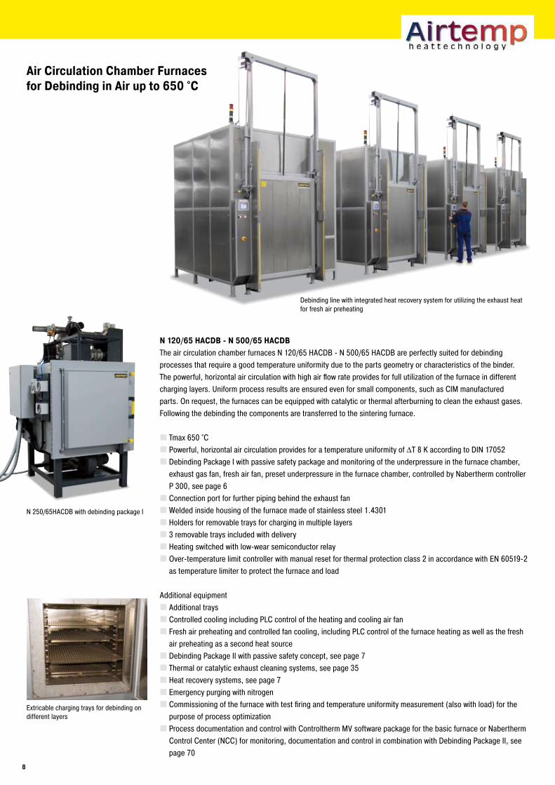
Air Circulation Chamber Furnaces for Debinding in Air up to ��0 °C
N 1�0/�� HACDB - N �00/�� HACDBThe air circulation chamber furnaces N 120/65 HACDB - N 500/65 HACDB are perfectly suited for debinding processes that require a good temperature uniformity due to the parts geometry or characteristics of the binder. The powerful, horizontal air circulation with high air flow rate provides for full utilization of the furnace in different charging layers. Uniform process results are ensured even for small components, such as CIM manufactured parts. On request, the furnaces can be equipped with catalytic or thermal afterburning to clean the exhaust gases. Following the debinding the components are transferred to the sintering furnace.
Tmax 650 °CPowerful, horizontal air circulation provides for a temperature uniformity of ΔT 8 K according to DIN 17052Debinding Package I with passive safety package and monitoring of the underpressure in the furnace chamber, exhaust gas fan, fresh air fan, preset underpressure in the furnace chamber, controlled by Nabertherm controller P 300, see page 6Connection port for further piping behind the exhaust fanWelded inside housing of the furnace made of stainless steel 1.4301Holders for removable trays for charging in multiple layers3 removable trays included with deliveryHeating switched with low-wear semiconductor relayOver-temperature limit controller with manual reset for thermal protection class 2 in accordance with EN 60519-2 as temperature limiter to protect the furnace and load
Additional equipmentAdditional traysControlled cooling including PLC control of the heating and cooling air fanFresh air preheating and controlled fan cooling, including PLC control of the furnace heating as well as the fresh air preheating as a second heat sourceDebinding Package II with passive safety concept, see page 7Thermal or catalytic exhaust cleaning systems, see page 35Heat recovery systems, see page 7Emergency purging with nitrogenCommissioning of the furnace with test firing and temperature uniformity measurement (also with load) for the purpose of process optimizationProcess documentation and control with Controltherm MV software package for the basic furnace or Nabertherm Control Center (NCC) for monitoring, documentation and control in combination with Debinding Package II, see page 70
Extricable charging trays for debinding on different layers
Debinding line with integrated heat recovery system for utilizing the exhaust heat for fresh air preheating
N 250/65HACDB with debinding package I
8
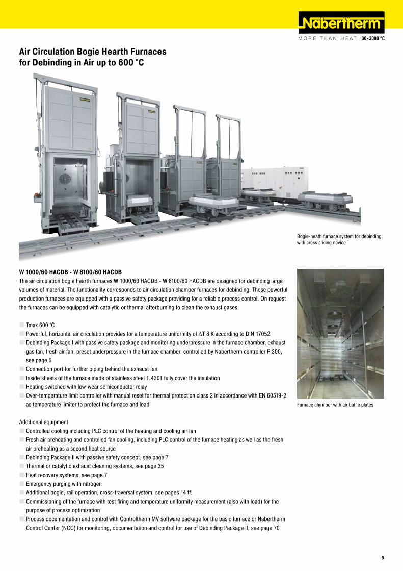
Air Circulation Bogie Hearth Furnaces for Debinding in Air up to �00 °C
W 1000/�0 HACDB - W 8100/�0 HACDBThe air circulation bogie hearth furnaces W 1000/60 HACDB - W 8100/60 HACDB are designed for debinding large volumes of material. The functionality corresponds to air circulation chamber furnaces for debinding. These powerful production furnaces are equipped with a passive safety package providing for a reliable process control. On request the furnaces can be equipped with catalytic or thermal afterburning to clean the exhaust gases.
Tmax 600 °CPowerful, horizontal air circulation provides for a temperature uniformity of ΔT 8 K according to DIN 17052Debinding Package I with passive safety package and monitoring underpressure in the furnace chamber, exhaust gas fan, fresh air fan, preset underpressure in the furnace chamber, controlled by Nabertherm controller P 300, see page 6Connection port for further piping behind the exhaust fanInside sheets of the furnace made of stainless steel 1.4301 fully cover the insulationHeating switched with low-wear semiconductor relayOver-temperature limit controller with manual reset for thermal protection class 2 in accordance with EN 60519-2 as temperature limiter to protect the furnace and load
Additional equipmentControlled cooling including PLC control of the heating and cooling air fanFresh air preheating and controlled fan cooling, including PLC control of the furnace heating as well as the fresh air preheating as a second heat sourceDebinding Package II with passive safety concept, see page 7Thermal or catalytic exhaust cleaning systems, see page 35Heat recovery systems, see page 7Emergency purging with nitrogenAdditional bogie, rail operation, cross-traversal system, see pages 14 ff.Commissioning of the furnace with test firing and temperature uniformity measurement (also with load) for the purpose of process optimizationProcess documentation and control with Controltherm MV software package for the basic furnace or Nabertherm Control Center (NCC) for monitoring, documentation and control for use of Debinding Package II, see page 70
Furnace chamber with air baffle plates
Bogie-heath furnace system for debinding with cross sliding device
�
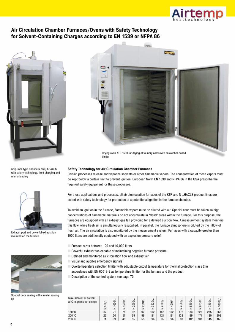
Drying oven KTR 1500 for drying of foundry cores with an alcohol-based binder
Air Circulation Chamber Furnaces/Ovens with Safety Technology for Solvent-Containing Charges according to EN 1��� or NFPA 8�
Special door sealing with circular sealing lip
Exhaust port and powerful exhaust fan mounted on the furnace
Ship-lock type furnace N 560/ 6HACLS with safety technology, front charging and rear unloading
Safety Technology for Air Circulation Chamber FurnacesCertain processes release and vaporize solvents or other flammable vapors. The concentration of these vapors must be kept below a certain limit to prevent ignition. European Norm EN 1539 and NFPA 86 in the USA prescribe the required safety equipment for these processes.
For these applications and processes, all air circirculation furnaces of the KTR and N ..HACLS product lines are suited with safety technology for protection of a potentional ignition in the furnace chamber.
To avoid an ignition in the furnace, flammable vapors must be diluted with air. Special care must be taken so high concentrations of flammable materials do not accumulate in “dead” areas within the furnace. For this purpose, the furnaces are equipped with an exhaust gas fan providing for a defined suction flow. A measurement system monitors this flow, while fresh air is simultaneously resupplied. In parallel, the furnace atmosphere is diluted by the inflow of fresh air. The air circulation is also monitored by the measurement system. Furnaces with a capacity greater than 1000 liters are additionally equipped with an explosion pressure relief.
Furnace sizes between 120 and 10,000 litersPowerful exhaust fan capable of maintaining negative furnace pressureDefined and monitored air circulation flow and exhaust airVisual and audible emergency signalsOvertemperature selection limiter with adjustable cutout temperature for thermal protection class 2 in accordance with EN 60519-2 as temperature limiter for the furnace and the productDescription of the control system see page 70
Max. amount of solvent at°C in grams per charge
N 56
0/..
N 10
00/..
N 15
00/..
N 20
00/..
N 20
10/..
N 39
20/..
N 40
00/..
N 40
10/..
N 45
00/..
N 56
00/..
N 67
50/..
N 72
00/..
N 10
000/
..
150 °C 37 71 76 92 92 162 162 162 172 183 225 235 263200 °C 26 50 57 69 99 121 121 121 132 139 171 180 203250 °C 21 39 45 55 55 96 96 96 98 112 137 145 165
10
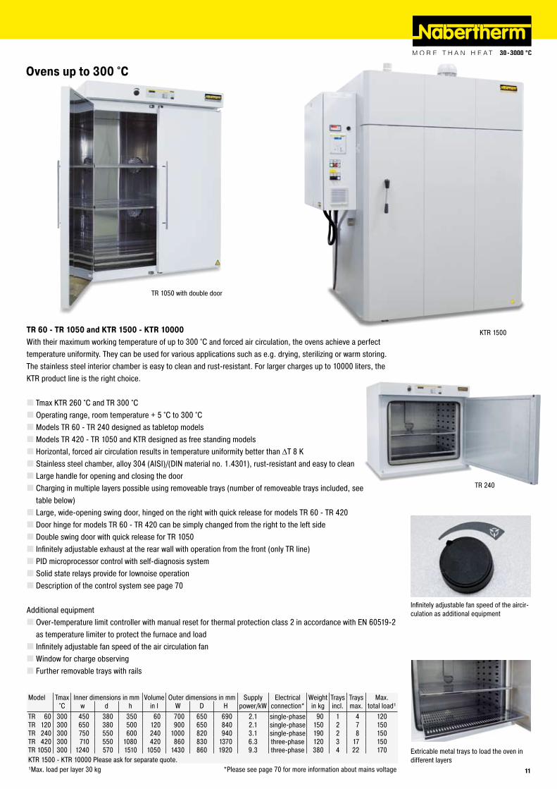
TR 240
KTR 1500
Ovens up to �00 °C
TR 1050 with double door
Infinitely adjustable fan speed of the aircir-culation as additional equipment
Extricable metal trays to load the oven in different layers
TR �0 - TR 10�0 and KTR 1�00 - KTR 10000With their maximum working temperature of up to 300 °C and forced air circulation, the ovens achieve a perfect temperature uniformity. They can be used for various applications such as e.g. drying, sterilizing or warm storing. The stainless steel interior chamber is easy to clean and rust-resistant. For larger charges up to 10000 liters, the KTR product line is the right choice.
Tmax KTR 260 °C and TR 300 °COperating range, room temperature + 5 °C to 300 °CModels TR 60 - TR 240 designed as tabletop modelsModels TR 420 - TR 1050 and KTR designed as free standing modelsHorizontal, forced air circulation results in temperature uniformity better than ΔT 8 KStainless steel chamber, alloy 304 (AISI)/(DIN material no. 1.4301), rust-resistant and easy to cleanLarge handle for opening and closing the doorCharging in multiple layers possible using removeable trays (number of removeable trays included, see table below)Large, wide-opening swing door, hinged on the right with quick release for models TR 60 - TR 420Door hinge for models TR 60 - TR 420 can be simply changed from the right to the left sideDouble swing door with quick release for TR 1050Infinitely adjustable exhaust at the rear wall with operation from the front (only TR line)PID microprocessor control with self-diagnosis systemSolid state relays provide for lownoise operationDescription of the control system see page 70
Additional equipmentOver-temperature limit controller with manual reset for thermal protection class 2 in accordance with EN 60519-2 as temperature limiter to protect the furnace and loadInfinitely adjustable fan speed of the air circulation fanWindow for charge observingFurther removable trays with rails
Model Tmax Inner dimensions in mm Volume Outer dimensions in mm Supply Electrical Weight Trays Trays Max.°C w d h in l W D H power/kW connection* in kg incl. max. total load¹
TR 60 300 450 380 350 60 700 650 690 2.1 single-phase 90 1 4 120TR 120 300 650 380 500 120 900 650 840 2.1 single-phase 150 2 7 150TR 240 300 750 550 600 240 1000 820 940 3.1 single-phase 190 2 8 150TR 420 300 710 550 1080 420 860 830 1370 6.3 three-phase 120 3 17 150TR 1050 300 1240 570 1510 1050 1430 860 1920 9.3 three-phase 380 4 22 170KTR 1500 - KTR 10000 Please ask for separate quote.¹Max. load per layer 30 kg *Please see page 70 for more information about mains voltage 11
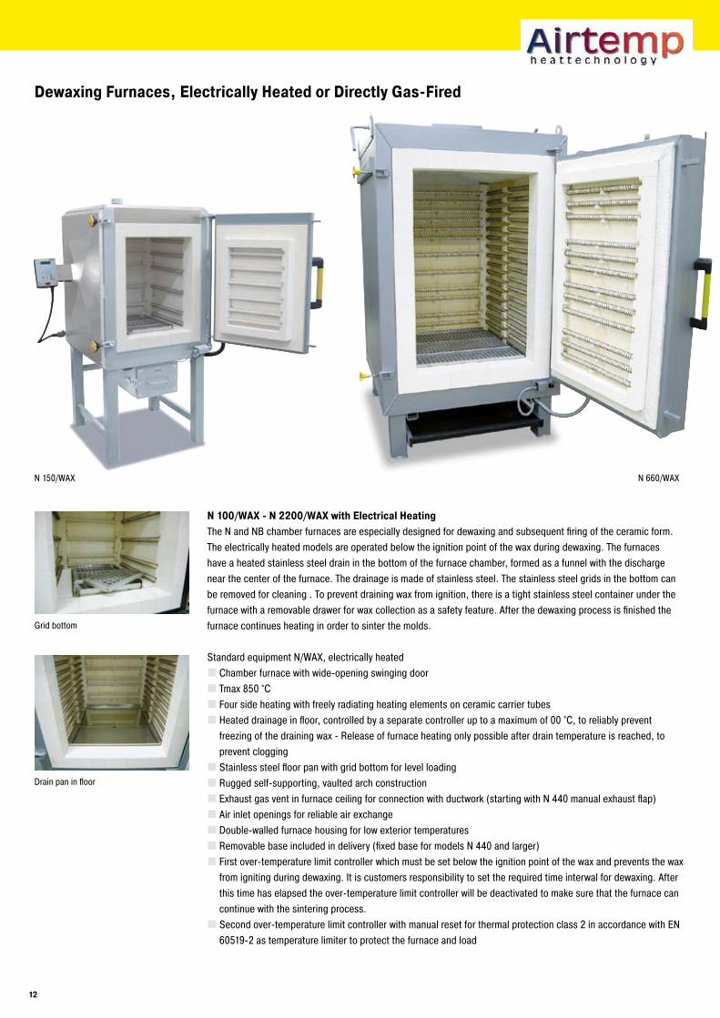
N 150/WAX N 660/WAX
Dewaxing Furnaces, Electrically Heated or Directly Gas-Fired
N 100/WAX - N ��00/WAX with Electrical HeatingThe N and NB chamber furnaces are especially designed for dewaxing and subsequent firing of the ceramic form. The electrically heated models are operated below the ignition point of the wax during dewaxing. The furnaces have a heated stainless steel drain in the bottom of the furnace chamber, formed as a funnel with the discharge near the center of the furnace. The drainage is made of stainless steel. The stainless steel grids in the bottom can be removed for cleaning . To prevent draining wax from ignition, there is a tight stainless steel container under the furnace with a removable drawer for wax collection as a safety feature. After the dewaxing process is finished the furnace continues heating in order to sinter the molds.
Standard equipment N/WAX, electrically heatedChamber furnace with wide-opening swinging doorTmax 850 °CFour side heating with freely radiating heating elements on ceramic carrier tubesHeated drainage in floor, controlled by a separate controller up to a maximum of 00 °C, to reliably prevent freezing of the draining wax - Release of furnace heating only possible after drain temperature is reached, to prevent cloggingStainless steel floor pan with grid bottom for level loadingRugged self-supporting, vaulted arch constructionExhaust gas vent in furnace ceiling for connection with ductwork (starting with N 440 manual exhaust flap)Air inlet openings for reliable air exchangeDouble-walled furnace housing for low exterior temperaturesRemovable base included in delivery (fixed base for models N 440 and larger)First over-temperature limit controller which must be set below the ignition point of the wax and prevents the wax from igniting during dewaxing. It is customers responsibility to set the required time interwal for dewaxing. After this time has elapsed the over-temperature limit controller will be deactivated to make sure that the furnace can continue with the sintering process.Second over-temperature limit controller with manual reset for thermal protection class 2 in accordance with EN 60519-2 as temperature limiter to protect the furnace and load
Grid bottom
Drain pan in floor
1�
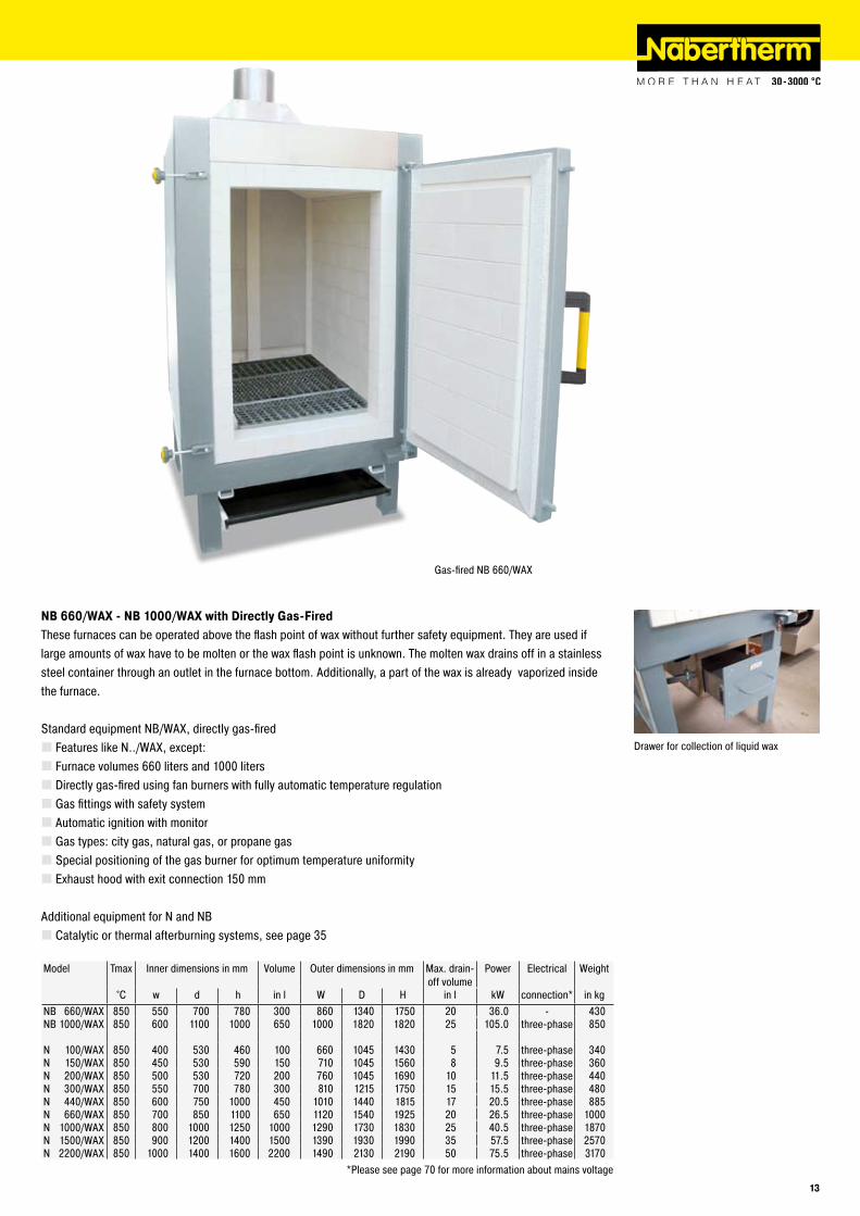
NB ��0/WAX - NB 1000/WAX with Directly Gas-FiredThese furnaces can be operated above the flash point of wax without further safety equipment. They are used if large amounts of wax have to be molten or the wax flash point is unknown. The molten wax drains off in a stainless steel container through an outlet in the furnace bottom. Additionally, a part of the wax is already vaporized inside the furnace.
Standard equipment NB/WAX, directly gas-firedFeatures like N../WAX, except:Furnace volumes 660 liters and 1000 litersDirectly gas-fired using fan burners with fully automatic temperature regulationGas fittings with safety systemAutomatic ignition with monitorGas types: city gas, natural gas, or propane gasSpecial positioning of the gas burner for optimum temperature uniformityExhaust hood with exit connection 150 mm
Additional equipment for N and NBCatalytic or thermal afterburning systems, see page 35
Drawer for collection of liquid wax
Gas-fired NB 660/WAX
Model Tmax Inner dimensions in mm Volume Outer dimensions in mm Max. drain-off volume
Power Electrical Weight
°C w d h in l W D H in l kW connection* in kgNB 660/WAX 850 550 700 780 300 860 1340 1750 20 36.0 - 430NB 1000/WAX 850 600 1100 1000 650 1000 1820 1820 25 105.0 three-phase 850
N 100/WAX 850 400 530 460 100 660 1045 1430 5 7.5 three-phase 340N 150/WAX 850 450 530 590 150 710 1045 1560 8 9.5 three-phase 360N 200/WAX 850 500 530 720 200 760 1045 1690 10 11.5 three-phase 440N 300/WAX 850 550 700 780 300 810 1215 1750 15 15.5 three-phase 480N 440/WAX 850 600 750 1000 450 1010 1440 1815 17 20.5 three-phase 885N 660/WAX 850 700 850 1100 650 1120 1540 1925 20 26.5 three-phase 1000N 1000/WAX 850 800 1000 1250 1000 1290 1730 1830 25 40.5 three-phase 1870N 1500/WAX 850 900 1200 1400 1500 1390 1930 1990 35 57.5 three-phase 2570N 2200/WAX 850 1000 1400 1600 2200 1490 2130 2190 50 75.5 three-phase 3170
*Please see page 70 for more information about mains voltage
1�
W 1500/H
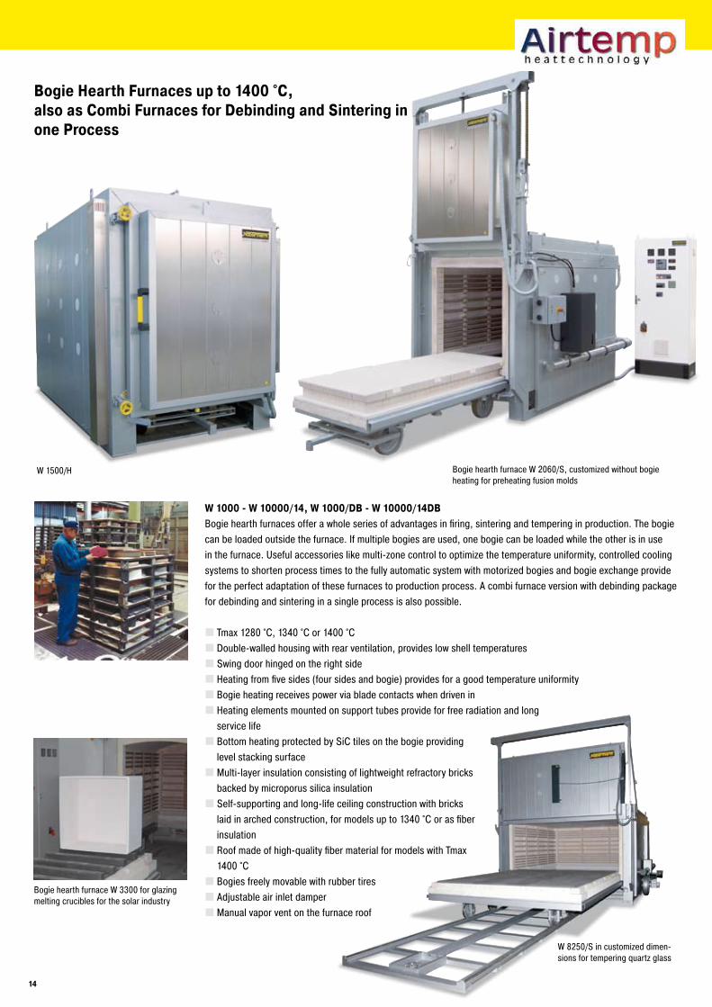
Bogie Hearth Furnaces up to 1400 °C, also as Combi Furnaces for Debinding and Sintering in one Process
Bogie hearth furnace W 2060/S, customized without bogie heating for preheating fusion molds
W 8250/S in customized dimen-sions for tempering quartz glass
Bogie hearth furnace W 3300 for glazing melting crucibles for the solar industry
W 1000 - W 10000/14, W 1000/DB - W 10000/14DBBogie hearth furnaces offer a whole series of advantages in firing, sintering and tempering in production. The bogie can be loaded outside the furnace. If multiple bogies are used, one bogie can be loaded while the other is in use in the furnace. Useful accessories like multi-zone control to optimize the temperature uniformity, controlled cooling systems to shorten process times to the fully automatic system with motorized bogies and bogie exchange provide for the perfect adaptation of these furnaces to production process. A combi furnace version with debinding package for debinding and sintering in a single process is also possible.
Tmax 1280 °C, 1340 °C or 1400 °CDouble-walled housing with rear ventilation, provides low shell temperaturesSwing door hinged on the right sideHeating from five sides (four sides and bogie) provides for a good temperature uniformityBogie heating receives power via blade contacts when driven inHeating elements mounted on support tubes provide for free radiation and long service lifeBottom heating protected by SiC tiles on the bogie providing level stacking surfaceMulti-layer insulation consisting of lightweight refractory bricks backed by microporus silica insulationSelf-supporting and long-life ceiling construction with bricks laid in arched construction, for models up to 1340 °C or as fiber insulationRoof made of high-quality fiber material for models with Tmax 1400 °CBogies freely movable with rubber tiresAdjustable air inlet damperManual vapor vent on the furnace roof
14
Over-temperature limit controller with manual reset for thermal protection class 2 in accordance with EN 60519-2 as temperature limiter to protect the furnace and load
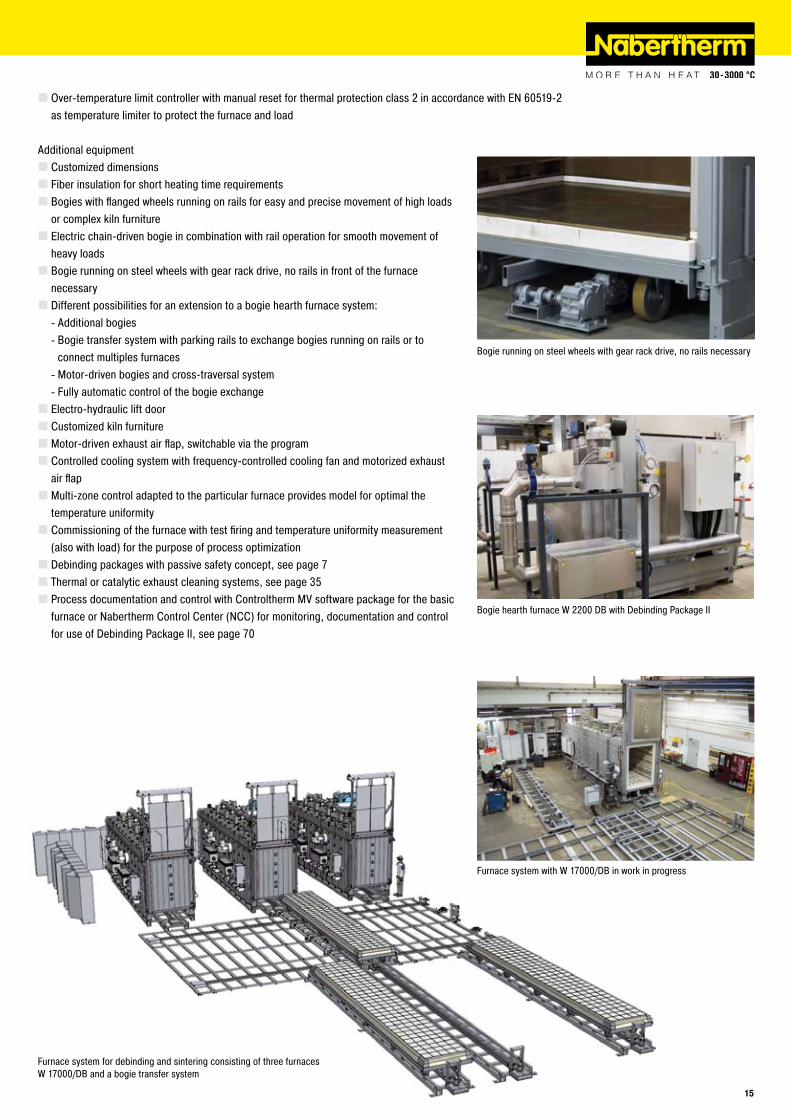
Additional equipmentCustomized dimensionsFiber insulation for short heating time requirementsBogies with flanged wheels running on rails for easy and precise movement of high loads or complex kiln furnitureElectric chain-driven bogie in combination with rail operation for smooth movement of heavy loadsBogie running on steel wheels with gear rack drive, no rails in front of the furnace necessaryDifferent possibilities for an extension to a bogie hearth furnace system:
Additional bogiesBogie transfer system with parking rails to exchange bogies running on rails or to connect multiples furnacesMotor-driven bogies and cross-traversal systemFully automatic control of the bogie exchange
Electro-hydraulic lift doorCustomized kiln furnitureMotor-driven exhaust air flap, switchable via the programControlled cooling system with frequency-controlled cooling fan and motorized exhaust air flapMulti-zone control adapted to the particular furnace provides model for optimal the temperature uniformityCommissioning of the furnace with test firing and temperature uniformity measurement (also with load) for the purpose of process optimizationDebinding packages with passive safety concept, see page 7Thermal or catalytic exhaust cleaning systems, see page 35Process documentation and control with Controltherm MV software package for the basic furnace or Nabertherm Control Center (NCC) for monitoring, documentation and control for use of Debinding Package II, see page 70
--
--
Bogie hearth furnace W 2200 DB with Debinding Package II
Bogie running on steel wheels with gear rack drive, no rails necessary
Furnace system for debinding and sintering consisting of three furnaces W 17000/DB and a bogie transfer system
Furnace system with W 17000/DB in work in progress
1�
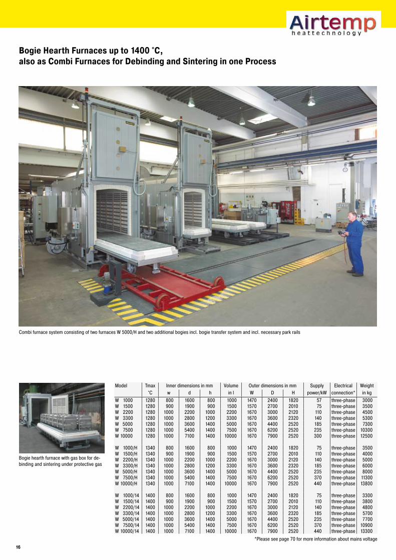
Bogie Hearth Furnaces up to 1400 °C, also as Combi Furnaces for Debinding and Sintering in one Process
Combi furnace system consisting of two furnaces W 5000/H and two additional bogies incl. bogie transfer system and incl. necessary park rails
Bogie hearth furnace with gas box for de-binding and sintering under protective gas
Model Tmax Inner dimensions in mm Volume Outer dimensions in mm Supply Electrical Weight°C w d h in l W D H power/kW connection* in kg
W 1000 1280 800 1600 800 1000 1470 2400 1820 57 three-phase 3000W 1500 1280 900 1900 900 1500 1570 2700 2010 75 three-phase 3500W 2200 1280 1000 2200 1000 2200 1670 3000 2120 110 three-phase 4500W 3300 1280 1000 2800 1200 3300 1670 3600 2320 140 three-phase 5300W 5000 1280 1000 3600 1400 5000 1670 4400 2520 185 three-phase 7300W 7500 1280 1000 5400 1400 7500 1670 6200 2520 235 three-phase 10300W 10000 1280 1000 7100 1400 10000 1670 7900 2520 300 three-phase 12500
W 1000/H 1340 800 1600 800 1000 1470 2400 1820 75 three-phase 3500W 1500/H 1340 900 1900 900 1500 1570 2700 2010 110 three-phase 4000W 2200/H 1340 1000 2200 1000 2200 1670 3000 2120 140 three-phase 5000W 3300/H 1340 1000 2800 1200 3300 1670 3600 2320 185 three-phase 6000W 5000/H 1340 1000 3600 1400 5000 1670 4400 2520 235 three-phase 8000W 7500/H 1340 1000 5400 1400 7500 1670 6200 2520 370 three-phase 11300W 10000/H 1340 1000 7100 1400 10000 1670 7900 2520 440 three-phase 13800
W 1000/14 1400 800 1600 800 1000 1470 2400 1820 75 three-phase 3300W 1500/14 1400 900 1900 900 1500 1570 2700 2010 110 three-phase 3800W 2200/14 1400 1000 2200 1000 2200 1670 3000 2120 140 three-phase 4800W 3300/14 1400 1000 2800 1200 3300 1670 3600 2320 185 three-phase 5700W 5000/14 1400 1000 3600 1400 5000 1670 4400 2520 235 three-phase 7700W 7500/14 1400 1000 5400 1400 7500 1670 6200 2520 370 three-phase 10900W 10000/14 1400 1000 7100 1400 10000 1670 7900 2520 440 three-phase 13300
*Please see page 70 for more information about mains voltage
1�
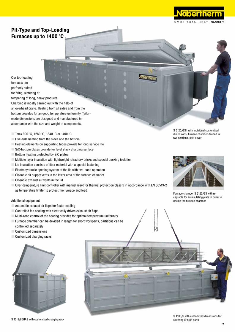
Pit-Type and Top-Loading Furnaces up to 1400 °C
Our top-loading furnaces are perfectly suited for firing, sintering or tempering of long, heavy products. Charging is mostly carried out with the help of an overhead crane. Heating from all sides and from thebottom provides for an good temperature uniformity. Tailor-made dimensions are designed and manufactured inaccordance with the size and weight of components.
Tmax 900 °C, 1280 °C, 1340 °C or 1400 °CFive-side heating from the sides and the bottomHeating elements on supporting tubes provide for long service lifeSiC-bottom plates provide for level stack charging surfaceBottom heating protected by SiC platesMultiple layer insulation with lightweight refractory bricks and special backing isolationLid insulation consists of fiber material with a special fasteningElectrohydraulic opening system of the lid with two-hand operationClosable air supply vents in the lower area of the furnace chamberClosable exhaust air vents in the lidOver-temperature limit controller with manual reset for thermal protection class 2 in accordance with EN 60519-2 as temperature limiter to protect the furnace and load
Additional equipmentAutomatic exhaust air flaps for faster coolingControlled fan cooling with electrically driven exhaust air flapsMulti-zone control of the heating provides for optimal temperature uniformityFurnace chamber can be devided in length for short workparts, partitions can be controlled separatelyCustomized dimensionsCustomized charging racks
S 5120/GS1 with individual customized dimensions, furnace chamber divided in two sections, split cover
S 1512/85HAS with customized charging rack
Furnace chamber S 5120/GS with re-ceptacle for an insulating plate in order to devide the furnace chamber
S 4100/S with customized dimensions for sintering of high parts
1�
H 1000/S
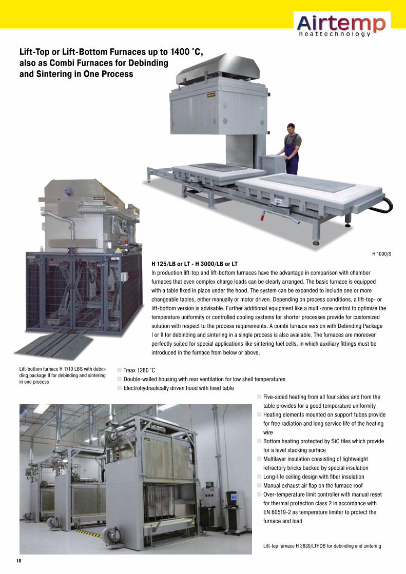
Lift-Top or Lift-Bottom Furnaces up to 1400 °C, also as Combi Furnaces for Debinding and Sintering in One Process
H 1��/LB or LT - H �000/LB or LTIn production lift-top and lift-bottom furnaces have the advantage in comparison with chamber furnaces that even complex charge loads can be clearly arranged. The basic furnace is equipped with a table fixed in place under the hood. The system can be expanded to include one or more changeable tables, either manually or motor driven. Depending on process conditions, a lift-top- or lift-bottom version is advisable. Further additional equipment like a multi-zone control to optimize the temperature uniformity or controlled cooling systems for shorter processes provide for customized solution with respect to the process requirements. A combi furnace version with Debinding Package I or II for debinding and sintering in a single process is also available. The furnaces are moreover perfectly suited for special applications like sintering fuel cells, in which auxiliary fittings must be introduced in the furnace from below or above.
Tmax 1280 °CDouble-walled housing with rear ventilation for low shell temperaturesElectrohydraulically driven hood with fixed table
Five-sided heating from all four sides and from the table provides for a good temperature uniformityHeating elements mounted on support tubes provide for free radiation and long service life of the heating wireBottom heating protected by SiC tiles which provide for a level stacking surfaceMultilayer insulation consisting of lightweight refractory bricks backed by special insulationLong-life ceiling design with fiber insulationManual exhaust air flap on the furnace roofOver-temperature limit controller with manual reset for thermal protection class 2 in accordance with EN 60519-2 as temperature limiter to protect the furnace and load
Lift-top furnace H 3630/LTHDB for debinding and sintering
Lift-bottom furnace H 1710 LBS with debin-ding package II for debinding and sintering in one process
18
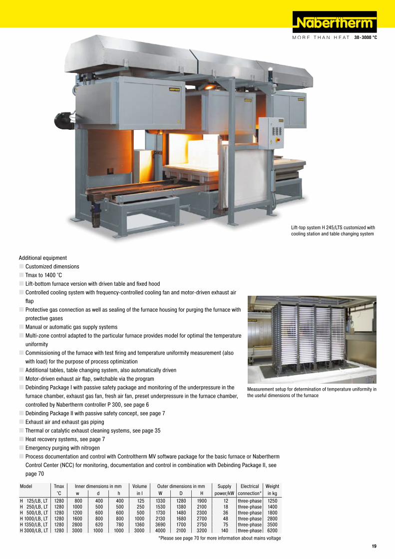
Additional equipmentCustomized dimensionsTmax to 1400 °CLift-bottom furnace version with driven table and fixed hoodControlled cooling system with frequency-controlled cooling fan and motor-driven exhaust air flapProtective gas connection as well as sealing of the furnace housing for purging the furnace with protective gasesManual or automatic gas supply systemsMulti-zone control adapted to the particular furnace provides model for optimal the temperature uniformityCommissioning of the furnace with test firing and temperature uniformity measurement (also with load) for the purpose of process optimizationAdditional tables, table changing system, also automatically drivenMotor-driven exhaust air flap, switchable via the programDebinding Package I with passive safety package and monitoring of the underpressure in the furnace chamber, exhaust gas fan, fresh air fan, preset underpressure in the furnace chamber, controlled by Nabertherm controller P 300, see page 6Debinding Package II with passive safety concept, see page 7Exhaust air and exhaust gas piping Thermal or catalytic exhaust cleaning systems, see page 35Heat recovery systems, see page 7Emergency purging with nitrogenProcess documentation and control with Controltherm MV software package for the basic furnace or Nabertherm Control Center (NCC) for monitoring, documentation and control in combination with Debinding Package II, see page 70
Lift-top system H 245/LTS customized with cooling station and table changing system
Measurement setup for determination of temperature uniformity in the useful dimensions of the furnace
Model Tmax Inner dimensions in mm Volume Outer dimensions in mm Supply Electrical Weight°C w d h in l W D H power/kW connection* in kg
H 125/LB, LT 1280 800 400 400 125 1330 1280 1900 12 three-phase 1250H 250/LB, LT 1280 1000 500 500 250 1530 1380 2100 18 three-phase 1400H 500/LB, LT 1280 1200 600 600 500 1730 1480 2300 36 three-phase 1800H 1000/LB, LT 1280 1600 800 800 1000 2130 1680 2700 48 three-phase 2800H 1350/LB, LT 1280 2800 620 780 1360 3690 1700 2750 75 three-phase 3500H 3000/LB, LT 1280 3000 1000 1000 3000 4000 2100 3200 140 three-phase 6200
*Please see page 70 for more information about mains voltage1�
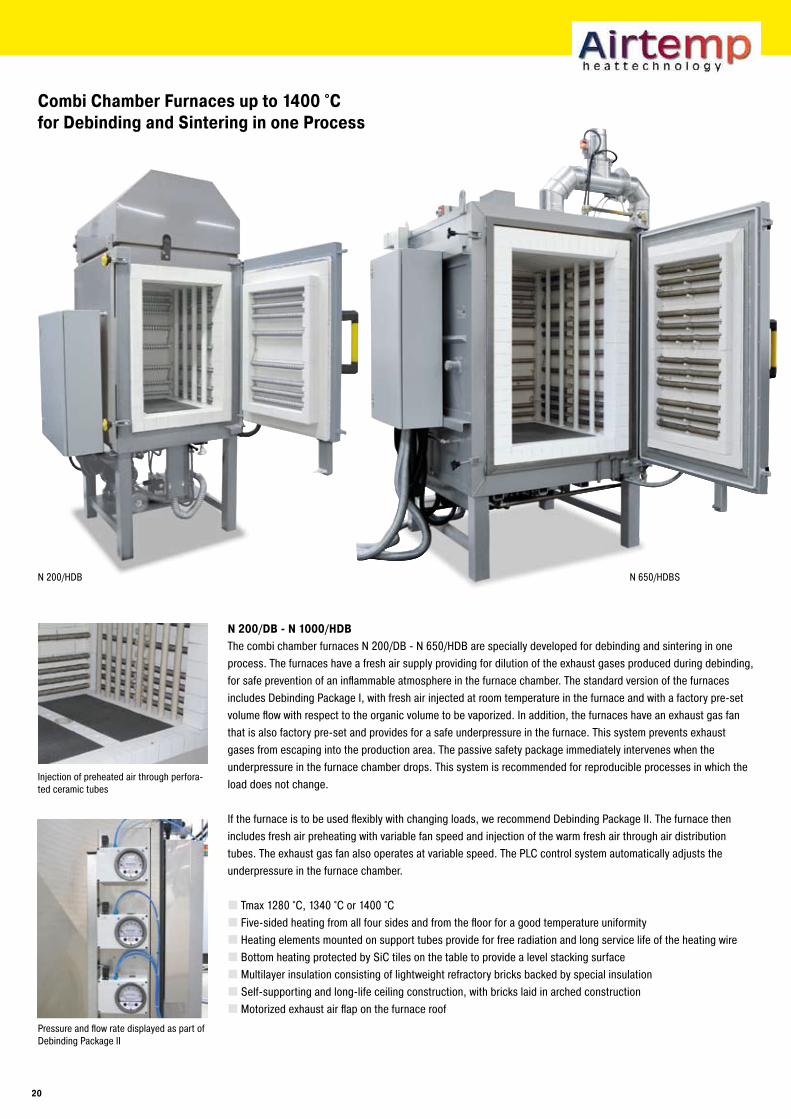
N 200/HDB N 650/HDBS
Combi Chamber Furnaces up to 1400 °C for Debinding and Sintering in one Process
Injection of preheated air through perfora-ted ceramic tubes
N �00/DB - N 1000/HDBThe combi chamber furnaces N 200/DB - N 650/HDB are specially developed for debinding and sintering in one process. The furnaces have a fresh air supply providing for dilution of the exhaust gases produced during debinding, for safe prevention of an inflammable atmosphere in the furnace chamber. The standard version of the furnaces includes Debinding Package I, with fresh air injected at room temperature in the furnace and with a factory pre-set volume flow with respect to the organic volume to be vaporized. In addition, the furnaces have an exhaust gas fan that is also factory pre-set and provides for a safe underpressure in the furnace. This system prevents exhaust gases from escaping into the production area. The passive safety package immediately intervenes when the underpressure in the furnace chamber drops. This system is recommended for reproducible processes in which the load does not change.
If the furnace is to be used flexibly with changing loads, we recommend Debinding Package II. The furnace then includes fresh air preheating with variable fan speed and injection of the warm fresh air through air distribution tubes. The exhaust gas fan also operates at variable speed. The PLC control system automatically adjusts the underpressure in the furnace chamber.
Tmax 1280 °C, 1340 °C or 1400 °CFive-sided heating from all four sides and from the floor for a good temperature uniformityHeating elements mounted on support tubes provide for free radiation and long service life of the heating wireBottom heating protected by SiC tiles on the table to provide a level stacking surfaceMultilayer insulation consisting of lightweight refractory bricks backed by special insulationSelf-supporting and long-life ceiling construction, with bricks laid in arched constructionMotorized exhaust air flap on the furnace roof
Pressure and flow rate displayed as part of Debinding Package II
�0
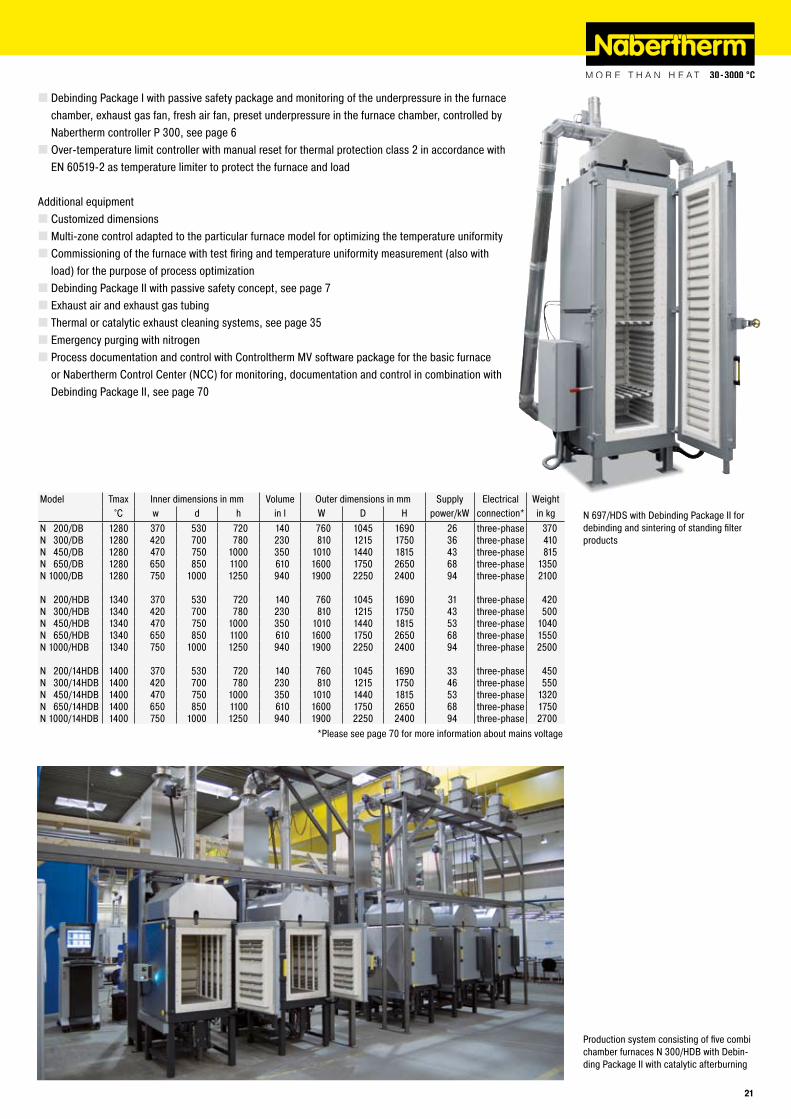
Debinding Package I with passive safety package and monitoring of the underpressure in the furnace chamber, exhaust gas fan, fresh air fan, preset underpressure in the furnace chamber, controlled by Nabertherm controller P 300, see page 6Over-temperature limit controller with manual reset for thermal protection class 2 in accordance with EN 60519-2 as temperature limiter to protect the furnace and load
Additional equipmentCustomized dimensionsMulti-zone control adapted to the particular furnace model for optimizing the temperature uniformityCommissioning of the furnace with test firing and temperature uniformity measurement (also with load) for the purpose of process optimizationDebinding Package II with passive safety concept, see page 7Exhaust air and exhaust gas tubingThermal or catalytic exhaust cleaning systems, see page 35Emergency purging with nitrogenProcess documentation and control with Controltherm MV software package for the basic furnace or Nabertherm Control Center (NCC) for monitoring, documentation and control in combination with Debinding Package II, see page 70
N 697/HDS with Debinding Package II for debinding and sintering of standing filter products
Production system consisting of five combi chamber furnaces N 300/HDB with Debin-ding Package II with catalytic afterburning
Model Tmax Inner dimensions in mm Volume Outer dimensions in mm Supply Electrical Weight°C w d h in l W D H power/kW connection* in kg
N 200/DB 1280 370 530 720 140 760 1045 1690 26 three-phase 370N 300/DB 1280 420 700 780 230 810 1215 1750 36 three-phase 410N 450/DB 1280 470 750 1000 350 1010 1440 1815 43 three-phase 815N 650/DB 1280 650 850 1100 610 1600 1750 2650 68 three-phase 1350N 1000/DB 1280 750 1000 1250 940 1900 2250 2400 94 three-phase 2100
N 200/HDB 1340 370 530 720 140 760 1045 1690 31 three-phase 420N 300/HDB 1340 420 700 780 230 810 1215 1750 43 three-phase 500N 450/HDB 1340 470 750 1000 350 1010 1440 1815 53 three-phase 1040N 650/HDB 1340 650 850 1100 610 1600 1750 2650 68 three-phase 1550N 1000/HDB 1340 750 1000 1250 940 1900 2250 2400 94 three-phase 2500
N 200/14HDB 1400 370 530 720 140 760 1045 1690 33 three-phase 450N 300/14HDB 1400 420 700 780 230 810 1215 1750 46 three-phase 550N 450/14HDB 1400 470 750 1000 350 1010 1440 1815 53 three-phase 1320N 650/14HDB 1400 650 850 1100 610 1600 1750 2650 68 three-phase 1750N 1000/14HDB 1400 750 1000 1250 940 1900 2250 2400 94 three-phase 2700
*Please see page 70 for more information about mains voltage
�1
N 100/G N 660/G
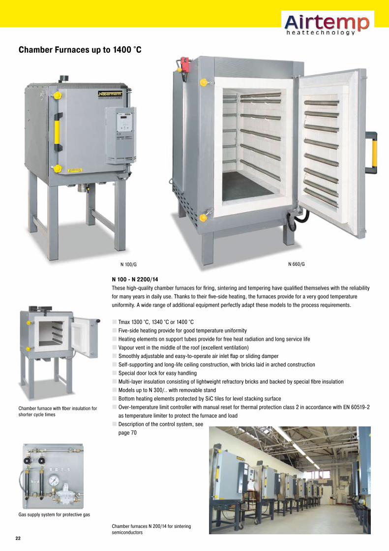
Chamber Furnaces up to 1400 °C
Chamber furnace with fiber insulation for shorter cycle times
N 100 - N ��00/14These high-quality chamber furnaces for firing, sintering and tempering have qualified themselves with the reliability for many years in daily use. Thanks to their five-side heating, the furnaces provide for a very good temperature uniformity. A wide range of additional equipment perfectly adapt these models to the process requirements.
Tmax 1300 °C, 1340 °C or 1400 °CFive-side heating provide for good temperature uniformityHeating elements on support tubes provide for free heat radiation and long service lifeVapour vent in the middle of the roof (excellent ventilation)Smoothly adjustable and easy-to-operate air inlet flap or sliding damperSelf-supporting and long-life ceiling construction, with bricks laid in arched constructionSpecial door lock for easy handlingMulti-layer insulation consisting of lightweight refractory bricks and backed by special fibre insulationModels up to N 300/.. with removable standBottom heating elements protected by SiC tiles for level stacking surfaceOver-temperature limit controller with manual reset for thermal protection class 2 in accordance with EN 60519-2 as temperature limiter to protect the furnace and loadDescription of the control system, see page 70
Chamber furnaces N 200/14 for sintering semiconductors
Gas supply system for protective gas
��
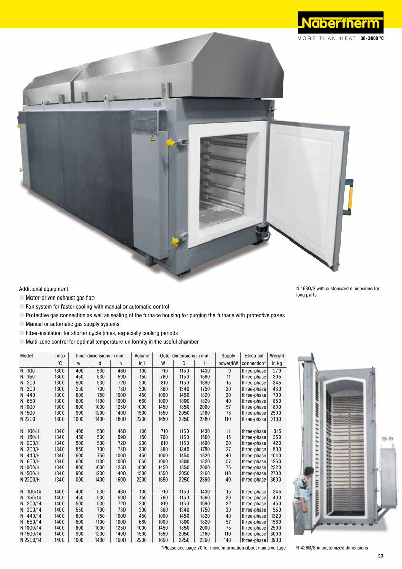
N 4260/S in customized dimensions
N 1680/S with customized dimensions for long parts
Additional equipmentMotor-driven exhaust gas flapFan system for faster cooling with manual or automatic controlProtective gas connection as well as sealing of the furnace housing for purging the furnace with protective gasesManual or automatic gas supply systemsFiber-insulation for shorter cycle times, especially cooling periodsMulti-zone control for optimal temperature uniformity in the useful chamber
Model Tmax Inner dimensions in mm Volume Outer dimensions in mm Supply Electrical Weight°C w d h in l W D H power/kW connection* in kg
N 100 1300 400 530 460 100 710 1150 1430 9 three-phase 270N 150 1300 450 530 590 150 760 1150 1560 11 three-phase 305N 200 1300 500 530 720 200 810 1150 1690 15 three-phase 345N 300 1300 550 700 780 300 860 1340 1750 20 three-phase 430N 440 1300 600 750 1000 450 1000 1450 1820 30 three-phase 700N 660 1300 600 1100 1000 660 1000 1800 1820 40 three-phase 850N 1000 1300 800 1000 1250 1000 1450 1850 2000 57 three-phase 1800N 1500 1300 900 1200 1400 1500 1550 2050 2160 75 three-phase 2500N 2200 1300 1000 1400 1600 2200 1650 2250 2360 110 three-phase 3100
N 100/H 1340 400 530 460 100 710 1150 1430 11 three-phase 315N 150/H 1340 450 530 590 150 760 1150 1560 15 three-phase 350N 200/H 1340 500 530 720 200 810 1150 1690 20 three-phase 420N 300/H 1340 550 700 780 300 860 1340 1750 27 three-phase 500N 440/H 1340 600 750 1000 450 1000 1450 1820 40 three-phase 1040N 660/H 1340 600 1100 1000 660 1000 1800 1820 57 three-phase 1260N 1000/H 1340 800 1000 1250 1000 1450 1850 2000 75 three-phase 2320N 1500/H 1340 900 1200 1400 1500 1550 2050 2160 110 three-phase 2700N 2200/H 1340 1000 1400 1600 2200 1650 2250 2360 140 three-phase 3600
N 100/14 1400 400 530 460 100 710 1150 1430 15 three-phase 345N 150/14 1400 450 530 590 150 760 1150 1560 20 three-phase 400N 200/14 1400 500 530 720 200 810 1150 1690 22 three-phase 450N 300/14 1400 550 700 780 300 860 1340 1750 30 three-phase 550N 440/14 1400 600 750 1000 450 1000 1450 1820 40 three-phase 1320N 660/14 1400 600 1100 1000 660 1000 1800 1820 57 three-phase 1560N 1000/14 1400 800 1000 1250 1000 1450 1850 2000 75 three-phase 2500N 1500/14 1400 900 1200 1400 1500 1550 2050 2160 110 three-phase 3000N 2200/14 1400 1000 1400 1600 2200 1650 2250 2360 140 three-phase 3900
*Please see page 70 for more information about mains voltage��
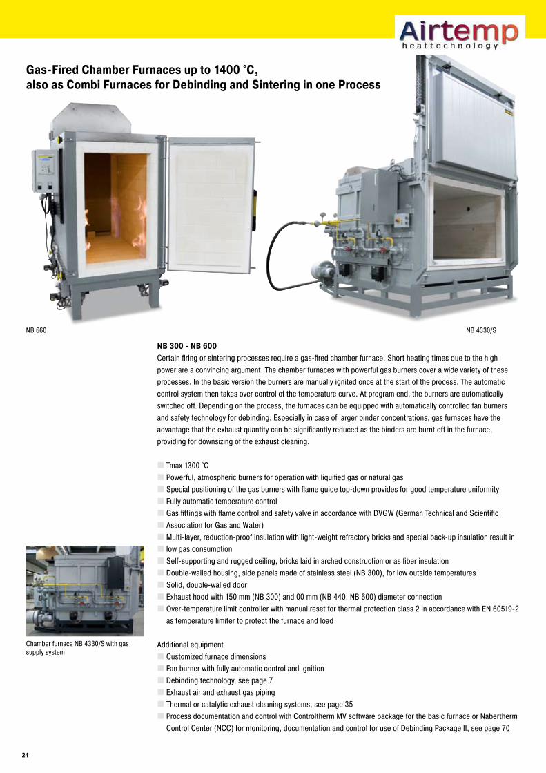
NB 660 NB 4330/S
Gas-Fired Chamber Furnaces up to 1400 °C,also as Combi Furnaces for Debinding and Sintering in one Process
NB �00 - NB �00Certain firing or sintering processes require a gas-fired chamber furnace. Short heating times due to the high power are a convincing argument. The chamber furnaces with powerful gas burners cover a wide variety of these processes. In the basic version the burners are manually ignited once at the start of the process. The automatic control system then takes over control of the temperature curve. At program end, the burners are automatically switched off. Depending on the process, the furnaces can be equipped with automatically controlled fan burners and safety technology for debinding. Especially in case of larger binder concentrations, gas furnaces have the advantage that the exhaust quantity can be significantly reduced as the binders are burnt off in the furnace, providing for downsizing of the exhaust cleaning.
Tmax 1300 °CPowerful, atmospheric burners for operation with liquified gas or natural gasSpecial positioning of the gas burners with flame guide top-down provides for good temperature uniformityFully automatic temperature controlGas fittings with flame control and safety valve in accordance with DVGW (German Technical and ScientificAssociation for Gas and Water)Multi-layer, reduction-proof insulation with light-weight refractory bricks and special back-up insulation result inlow gas consumptionSelf-supporting and rugged ceiling, bricks laid in arched construction or as fiber insulationDouble-walled housing, side panels made of stainless steel (NB 300), for low outside temperaturesSolid, double-walled doorExhaust hood with 150 mm (NB 300) and 00 mm (NB 440, NB 600) diameter connectionOver-temperature limit controller with manual reset for thermal protection class 2 in accordance with EN 60519-2 as temperature limiter to protect the furnace and load
Additional equipmentCustomized furnace dimensionsFan burner with fully automatic control and ignitionDebinding technology, see page 7Exhaust air and exhaust gas pipingThermal or catalytic exhaust cleaning systems, see page 35Process documentation and control with Controltherm MV software package for the basic furnace or Nabertherm Control Center (NCC) for monitoring, documentation and control for use of Debinding Package II, see page 70
Chamber furnace NB 4330/S with gas supply system
�4
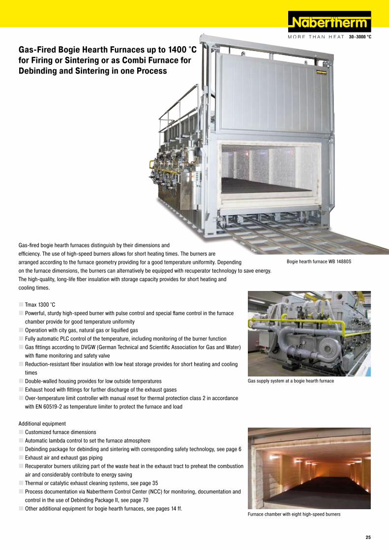
Gas-Fired Bogie Hearth Furnaces up to 1400 °Cfor Firing or Sintering or as Combi Furnace for Debinding and Sintering in one Process
Gas-fired bogie hearth furnaces distinguish by their dimensions and efficiency. The use of high-speed burners allows for short heating times. The burners are arranged according to the furnace geometry providing for a good temperature uniformity. Depending on the furnace dimensions, the burners can alternatively be equipped with recuperator technology to save energy. The high-quality, long-life fiber insulation with storage capacity provides for short heating and cooling times.
Tmax 1300 °CPowerful, sturdy high-speed burner with pulse control and special flame control in the furnace chamber provide for good temperature uniformityOperation with city gas, natural gas or liquified gasFully automatic PLC control of the temperature, including monitoring of the burner functionGas fittings according to DVGW (German Technical and Scientific Association for Gas and Water) with flame monitoring and safety valveReduction-resistant fiber insulation with low heat storage provides for short heating and cooling timesDouble-walled housing provides for low outside temperaturesExhaust hood with fittings for further discharge of the exhaust gasesOver-temperature limit controller with manual reset for thermal protection class 2 in accordance with EN 60519-2 as temperature limiter to protect the furnace and load
Additional equipmentCustomized furnace dimensionsAutomatic lambda control to set the furnace atmosphereDebinding package for debinding and sintering with corresponding safety technology, see page 6Exhaust air and exhaust gas pipingRecuperator burners utilizing part of the waste heat in the exhaust tract to preheat the combustion air and considerably contribute to energy savingThermal or catalytic exhaust cleaning systems, see page 35Process documentation via Nabertherm Control Center (NCC) for monitoring, documentation and control in the use of Debinding Package II, see page 70Other additional equipment for bogie hearth furnaces, see pages 14 ff.
Bogie hearth furnace WB 14880S
Gas supply system at a bogie hearth furnace
Furnace chamber with eight high-speed burners
��
HT 64/17 LT
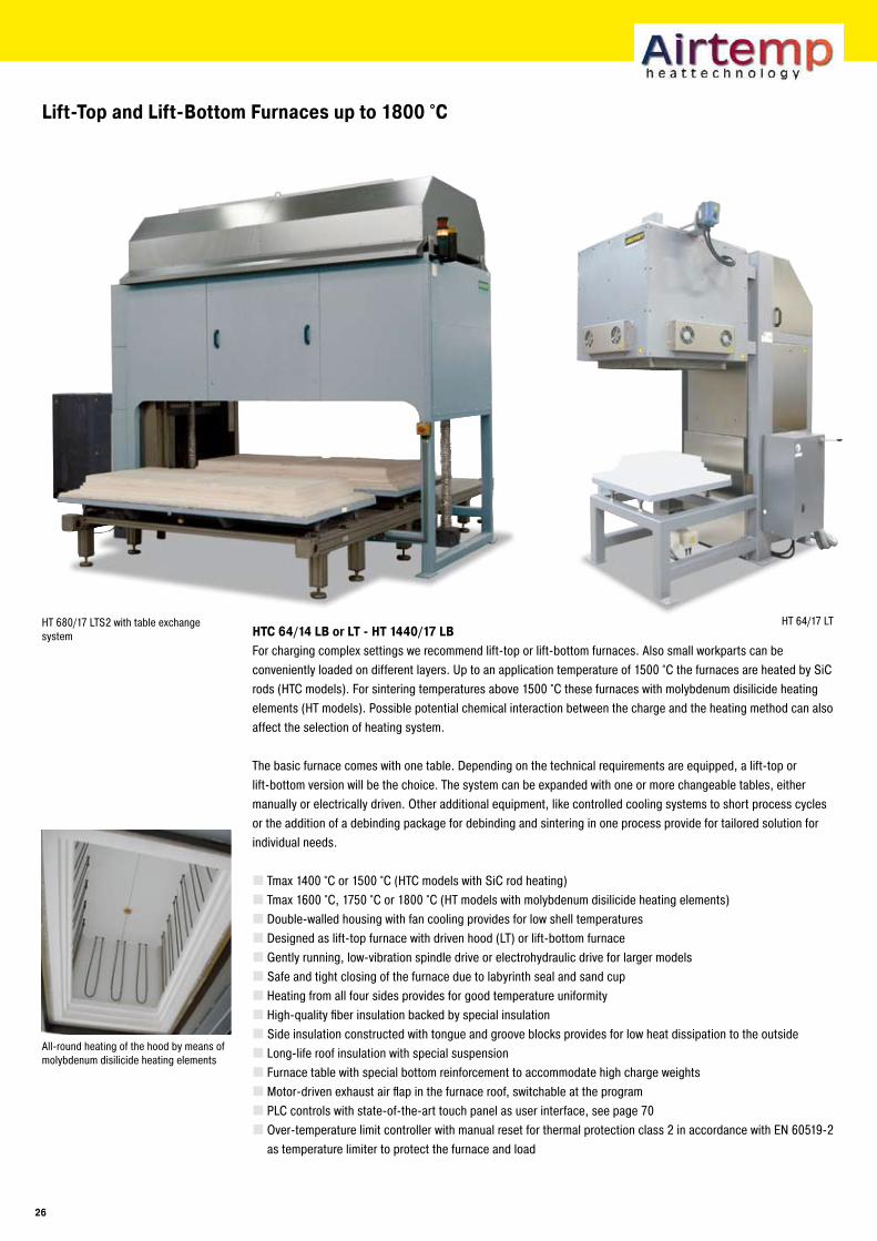
Lift-Top and Lift-Bottom Furnaces up to 1800 °C
HT 680/17 LTS2 with table exchange system HTC �4/14 LB or LT - HT 1440/1� LB
For charging complex settings we recommend lift-top or lift-bottom furnaces. Also small workparts can be conveniently loaded on different layers. Up to an application temperature of 1500 °C the furnaces are heated by SiC rods (HTC models). For sintering temperatures above 1500 °C these furnaces with molybdenum disilicide heating elements (HT models). Possible potential chemical interaction between the charge and the heating method can also affect the selection of heating system.
The basic furnace comes with one table. Depending on the technical requirements are equipped, a lift-top or lift-bottom version will be the choice. The system can be expanded with one or more changeable tables, either manually or electrically driven. Other additional equipment, like controlled cooling systems to short process cycles or the addition of a debinding package for debinding and sintering in one process provide for tailored solution for individual needs.
Tmax 1400 °C or 1500 °C (HTC models with SiC rod heating)Tmax 1600 °C, 1750 °C or 1800 °C (HT models with molybdenum disilicide heating elements)Double-walled housing with fan cooling provides for low shell temperaturesDesigned as lift-top furnace with driven hood (LT) or lift-bottom furnaceGently running, low-vibration spindle drive or electrohydraulic drive for larger modelsSafe and tight closing of the furnace due to labyrinth seal and sand cupHeating from all four sides provides for good temperature uniformityHigh-quality fiber insulation backed by special insulationSide insulation constructed with tongue and groove blocks provides for low heat dissipation to the outsideLong-life roof insulation with special suspensionFurnace table with special bottom reinforcement to accommodate high charge weightsMotor-driven exhaust air flap in the furnace roof, switchable at the programPLC controls with state-of-the-art touch panel as user interface, see page 70Over-temperature limit controller with manual reset for thermal protection class 2 in accordance with EN 60519-2 as temperature limiter to protect the furnace and load
All-round heating of the hood by means of molybdenum disilicide heating elements
��
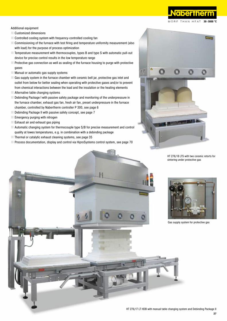
Additional equipmentCustomized dimensionsControlled cooling system with frequency-controlled cooling fanCommissioning of the furnace with test firing and temperature uniformity measurement (also with load) for the purpose of process optimizationTemperature measurement with thermocouples, types B and type S with automatic pull-out device for precise control results in the low temperature rangeProtective gas connection as well as sealing of the furnace housing to purge with protective gasesManual or automatic gas supply systemsGas supply system in the furnace chamber with ceramic bell jar, protective gas inlet and outlet from below for better sealing when operating with protective gases and/or to prevent from chemical interactions between the load and the insulation or the heating elementsAlternative table changing systemsDebinding Package I with passive safety package and monitoring of the underpressure in the furnace chamber, exhaust gas fan, fresh air fan, preset underpressure in the furnace chamber, controlled by Nabertherm controller P 300, see page 6Debinding Package II with passive safety concept, see page 7Emergency purging with nitrogenExhaust air and exhaust gas pipingAutomatic changing system for thermocouple type S/B for precise measurement and control quality at lowes temperatures, e.g. in combination with a debinding packageThermal or catalytic exhaust cleaning systems, see page 35Process documentation, display and control via HiproSystems control system, see page 70
Gas supply system for protective gas
HT 276/17 LT HDB with manual table changing system and Debinding Package II
HT 276/18 LTS with two ceramic retorts for sintering under protective gas
��
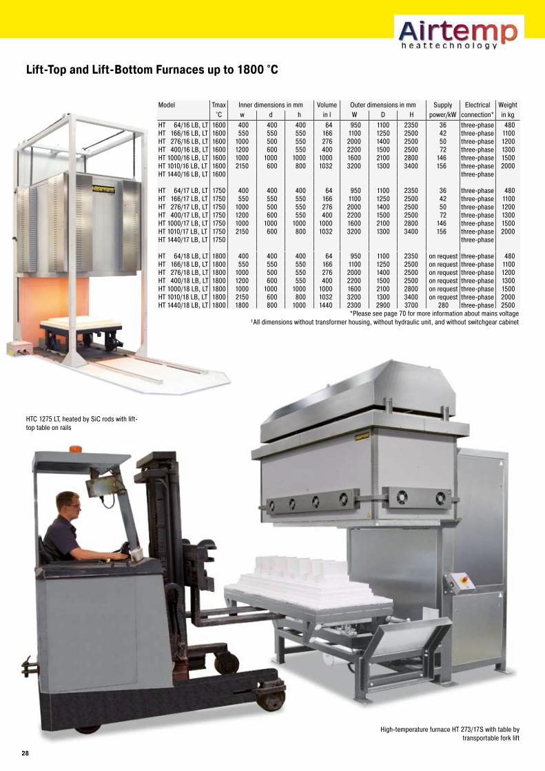
Lift-Top and Lift-Bottom Furnaces up to 1800 °C
High-temperature furnace HT 273/17S with table by transportable fork lift
HTC 1275 LT, heated by SiC rods with lift-top table on rails
Model Tmax Inner dimensions in mm Volume Outer dimensions in mm Supply Electrical Weight°C w d h in l W D H power/kW connection* in kg
HT 64/16 LB, LT 1600 400 400 400 64 950 1100 2350 36 three-phase 480HT 166/16 LB, LT 1600 550 550 550 166 1100 1250 2500 42 three-phase 1100HT 276/16 LB, LT 1600 1000 500 550 276 2000 1400 2500 50 three-phase 1200HT 400/16 LB, LT 1600 1200 600 550 400 2200 1500 2500 72 three-phase 1300HT 1000/16 LB, LT 1600 1000 1000 1000 1000 1600 2100 2800 146 three-phase 1500HT 1010/16 LB, LT 1600 2150 600 800 1032 3200 1300 3400 156 three-phase 2000HT 1440/16 LB, LT 1600 three-phase
HT 64/17 LB, LT 1750 400 400 400 64 950 1100 2350 36 three-phase 480HT 166/17 LB, LT 1750 550 550 550 166 1100 1250 2500 42 three-phase 1100HT 276/17 LB, LT 1750 1000 500 550 276 2000 1400 2500 50 three-phase 1200HT 400/17 LB, LT 1750 1200 600 550 400 2200 1500 2500 72 three-phase 1300HT 1000/17 LB, LT 1750 1000 1000 1000 1000 1600 2100 2800 146 three-phase 1500HT 1010/17 LB, LT 1750 2150 600 800 1032 3200 1300 3400 156 three-phase 2000HT 1440/17 LB, LT 1750 three-phase
HT 64/18 LB, LT 1800 400 400 400 64 950 1100 2350 on request three-phase 480HT 166/18 LB, LT 1800 550 550 550 166 1100 1250 2500 on request three-phase 1100HT 276/18 LB, LT 1800 1000 500 550 276 2000 1400 2500 on request three-phase 1200HT 400/18 LB, LT 1800 1200 600 550 400 2200 1500 2500 on request three-phase 1300HT 1000/18 LB, LT 1800 1000 1000 1000 1000 1600 2100 2800 on request three-phase 1500HT 1010/18 LB, LT 1800 2150 600 800 1032 3200 1300 3400 on request three-phase 2000HT 1440/18 LB, LT 1800 1800 800 1000 1440 2300 2900 3700 280 three-phase 2500
*Please see page 70 for more information about mains voltage¹All dimensions without transformer housing, without hydraulic unit, and without switchgear cabinet
�8
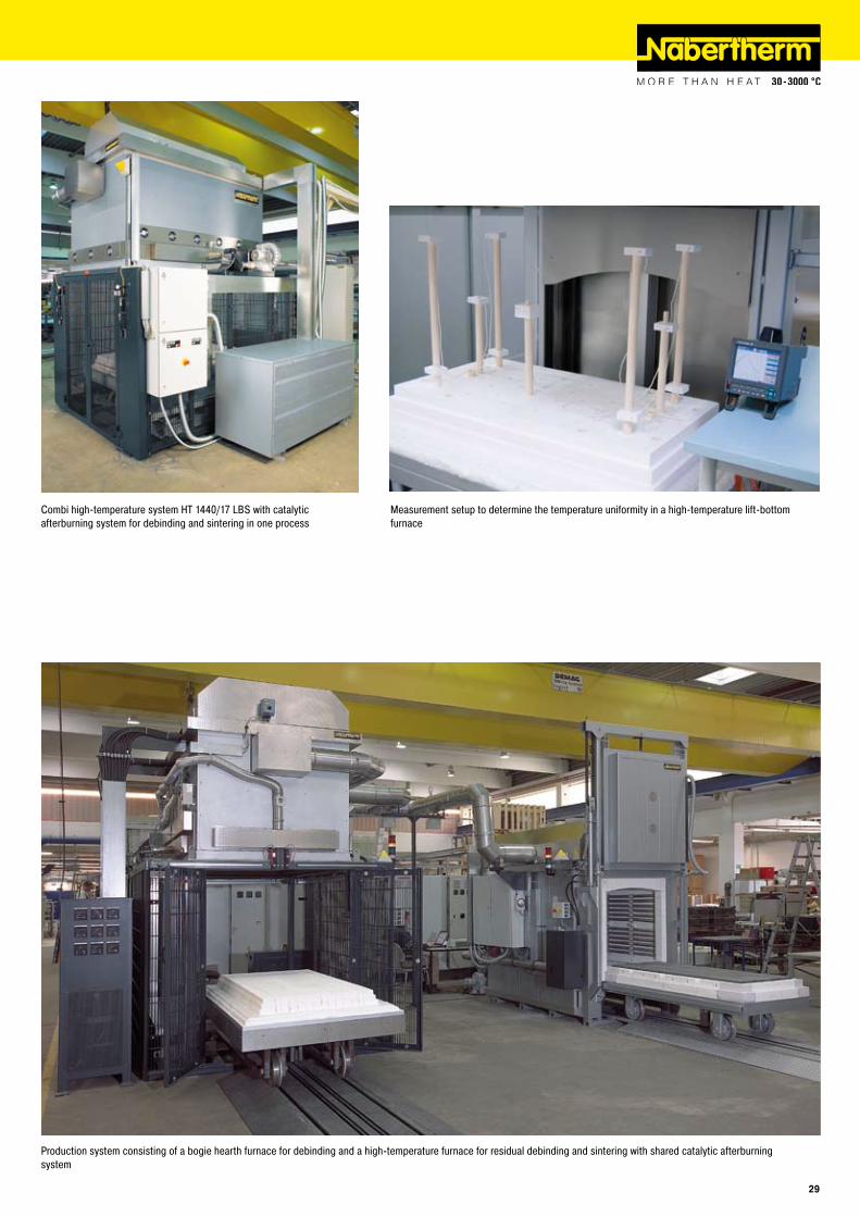
Combi high-temperature system HT 1440/17 LBS with catalytic afterburning system for debinding and sintering in one process
Measurement setup to determine the temperature uniformity in a high-temperature lift-bottom furnace
Production system consisting of a bogie hearth furnace for debinding and a high-temperature furnace for residual debinding and sintering with shared catalytic afterburning system
��
HT 16/16
High-Temperature Chamber Furnaces with Fiber Insulation up to 1800 °C
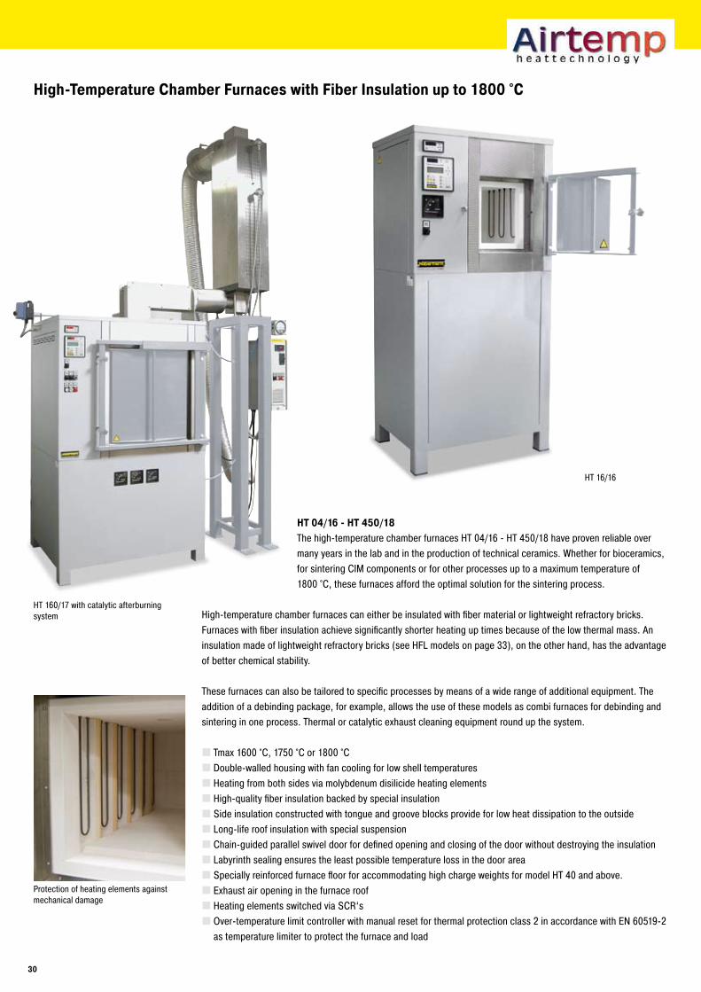
HT 04/1� - HT 4�0/18The high-temperature chamber furnaces HT 04/16 - HT 450/18 have proven reliable over many years in the lab and in the production of technical ceramics. Whether for bioceramics, for sintering CIM components or for other processes up to a maximum temperature of 1800 °C, these furnaces afford the optimal solution for the sintering process.
High-temperature chamber furnaces can either be insulated with fiber material or lightweight refractory bricks. Furnaces with fiber insulation achieve significantly shorter heating up times because of the low thermal mass. An insulation made of lightweight refractory bricks (see HFL models on page 33), on the other hand, has the advantage of better chemical stability.
These furnaces can also be tailored to specific processes by means of a wide range of additional equipment. The addition of a debinding package, for example, allows the use of these models as combi furnaces for debinding and sintering in one process. Thermal or catalytic exhaust cleaning equipment round up the system.
Tmax 1600 °C, 1750 °C or 1800 °C Double-walled housing with fan cooling for low shell temperaturesHeating from both sides via molybdenum disilicide heating elementsHigh-quality fiber insulation backed by special insulationSide insulation constructed with tongue and groove blocks provide for low heat dissipation to the outsideLong-life roof insulation with special suspensionChain-guided parallel swivel door for defined opening and closing of the door without destroying the insulationLabyrinth sealing ensures the least possible temperature loss in the door areaSpecially reinforced furnace floor for accommodating high charge weights for model HT 40 and above.Exhaust air opening in the furnace roofHeating elements switched via SCR‘sOver-temperature limit controller with manual reset for thermal protection class 2 in accordance with EN 60519-2 as temperature limiter to protect the furnace and load
HT 160/17 with catalytic afterburning system
Protection of heating elements against mechanical damage
�0
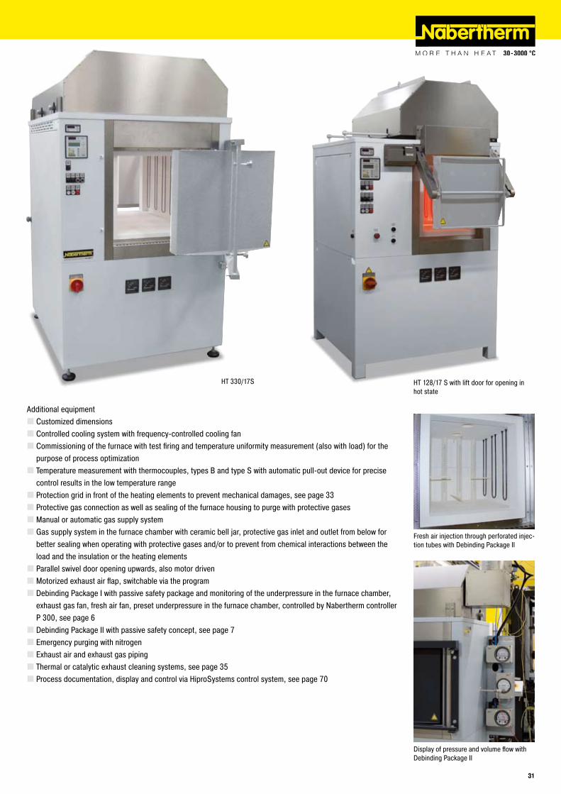
HT 330/17S
Additional equipmentCustomized dimensionsControlled cooling system with frequency-controlled cooling fanCommissioning of the furnace with test firing and temperature uniformity measurement (also with load) for the purpose of process optimizationTemperature measurement with thermocouples, types B and type S with automatic pull-out device for precise control results in the low temperature rangeProtection grid in front of the heating elements to prevent mechanical damages, see page 33Protective gas connection as well as sealing of the furnace housing to purge with protective gasesManual or automatic gas supply systemGas supply system in the furnace chamber with ceramic bell jar, protective gas inlet and outlet from below for better sealing when operating with protective gases and/or to prevent from chemical interactions between the load and the insulation or the heating elementsParallel swivel door opening upwards, also motor drivenMotorized exhaust air flap, switchable via the programDebinding Package I with passive safety package and monitoring of the underpressure in the furnace chamber, exhaust gas fan, fresh air fan, preset underpressure in the furnace chamber, controlled by Nabertherm controller P 300, see page 6Debinding Package II with passive safety concept, see page 7Emergency purging with nitrogenExhaust air and exhaust gas pipingThermal or catalytic exhaust cleaning systems, see page 35Process documentation, display and control via HiproSystems control system, see page 70
Fresh air injection through perforated injec-tion tubes with Debinding Package II
Display of pressure and volume flow with Debinding Package II
HT 128/17 S with lift door for opening in hot state
�1
High-Temperature Chamber Furnaces with Fiber Insulation up to 1800 °C
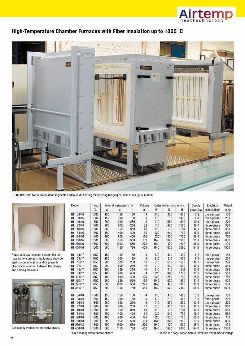
Retort with gas injection through the fur-nace bottom protects the furnace chamber against contamination and/or prevents chemical interaction between the charge and heating elements
HT 1000/17 with two movable door segments and fourside heating for sintering hanging ceramic tubes up to 1700 °C
Gas supply system for protective gases
Model Tmax Inner dimensions in mm Volume Outer dimensions in mm Supply Electrical Weight°C w d h in l W D H power/kW connection* in kg
HT 04/16 1600 150 150 150 4 610 470 1400 5.2 three-phase¹ 150HT 08/16 1600 150 300 150 8 610 610 1400 8.0 three-phase¹ 200HT 16/16 1600 200 300 260 16 710 650 1500 12.0 three-phase¹ 270HT 32/16 1600 200 600 260 32 710 930 1500 18.0 three-phase 350HT 40/16 1600 300 350 350 40 810 710 1610 12.0 three-phase 380HT 64/16 1600 400 400 400 64 1020 840 1700 18.0 three-phase 550HT 128/16 1600 400 800 400 128 1020 1250 1700 26.0 three-phase 750HT 160/16 1600 500 550 550 160 1140 1020 1900 21.0 three-phase 800HT 276/16 1600 500 1000 550 276 1140 1470 1900 36.0 three-phase 1100HT 450/16 1600 500 1150 780 450 1140 1620 2060 64.0 three-phase 1500
HT 04/17 1750 150 150 150 4 610 470 1400 5.2 three-phase¹ 150HT 08/17 1750 150 300 150 8 610 610 1400 8.0 three-phase¹ 200HT 16/17 1750 200 300 260 16 710 650 1500 12.0 three-phase¹ 270HT 32/17 1750 200 600 260 32 710 930 1500 18.0 three-phase 350HT 40/17 1750 300 350 350 40 810 710 1610 12.0 three-phase 380HT 64/17 1750 400 400 400 64 1020 840 1700 18.0 three-phase 550HT 128/17 1750 400 800 400 128 1020 1250 1700 26.0 three-phase 750HT 160/17 1750 500 550 550 160 1140 1020 1900 21.0 three-phase 800HT 276/17 1750 500 1000 550 276 1140 1470 1900 36.0 three-phase 1100HT 450/17 1750 500 1150 780 450 1140 1620 2060 64.0 three-phase 1500
HT 04/18 1800 150 150 150 4 610 470 1400 5.2 three-phase¹ 150HT 08/18 1800 150 300 150 8 610 610 1400 9.0 three-phase¹ 200HT 16/18 1800 200 300 260 16 710 650 1500 12.0 three-phase¹ 270HT 32/18 1800 200 600 260 32 710 930 1500 18.0 three-phase 350HT 40/18 1800 300 350 350 40 810 710 1610 12.0 three-phase 380HT 64/18 1800 400 400 400 64 1020 840 1700 18.0 three-phase 550HT 128/18 1800 400 800 400 128 1020 1250 1700 26.0 three-phase 750HT 160/18 1800 500 550 550 160 1140 1020 1900 21.0 three-phase 800HT 276/18 1800 500 1000 550 276 1140 1470 1900 36.0 three-phase 1100HT 450/18 1800 500 1150 780 450 1140 1620 2060 64.0 three-phase 1500¹Only heating between two phases *Please see page 70 for more information about mains voltage
��
Chamber Furnaces with Refractory Insulation up to 1�00 °C
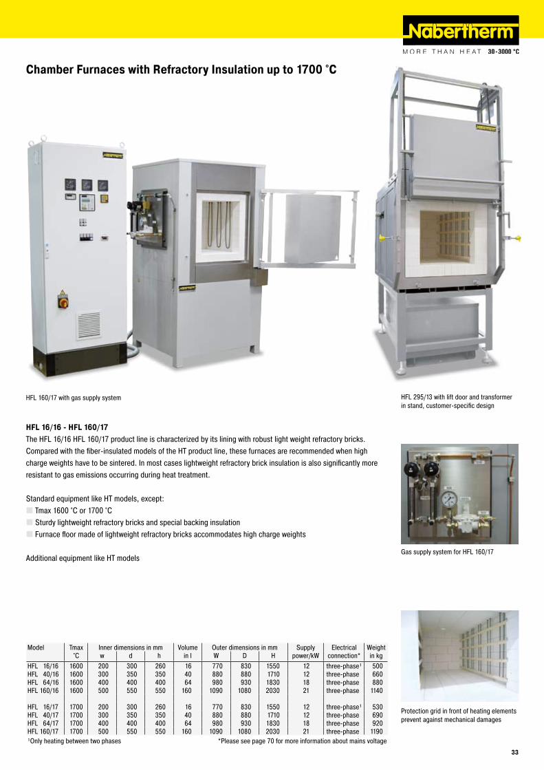
HFL 295/13 with lift door and transformer in stand, customer-specific design
Protection grid in front of heating elements prevent against mechanical damages
HFL 160/17 with gas supply system
Gas supply system for HFL 160/17
HFL 1�/1� - HFL 1�0/1�The HFL 16/16 HFL 160/17 product line is characterized by its lining with robust light weight refractory bricks. Compared with the fiber-insulated models of the HT product line, these furnaces are recommended when high charge weights have to be sintered. In most cases lightweight refractory brick insulation is also significantly more resistant to gas emissions occurring during heat treatment.
Standard equipment like HT models, except:Tmax 1600 °C or 1700 °CSturdy lightweight refractory bricks and special backing insulationFurnace floor made of lightweight refractory bricks accommodates high charge weights
Additional equipment like HT models
Model Tmax Inner dimensions in mm Volume Outer dimensions in mm Supply Electrical Weight°C w d h in l W D H power/kW connection* in kg
HFL 16/16 1600 200 300 260 16 770 830 1550 12 three-phase¹ 500HFL 40/16 1600 300 350 350 40 880 880 1710 12 three-phase 660HFL 64/16 1600 400 400 400 64 980 930 1830 18 three-phase 880HFL 160/16 1600 500 550 550 160 1090 1080 2030 21 three-phase 1140
HFL 16/17 1700 200 300 260 16 770 830 1550 12 three-phase¹ 530HFL 40/17 1700 300 350 350 40 880 880 1710 12 three-phase 690HFL 64/17 1700 400 400 400 64 980 930 1830 18 three-phase 920HFL 160/17 1700 500 550 550 160 1090 1080 2030 21 three-phase 1190¹Only heating between two phases *Please see page 70 for more information about mains voltage
��
HTB 645/17
Gas-Fired Chamber Furnaces up to 1�00 °C
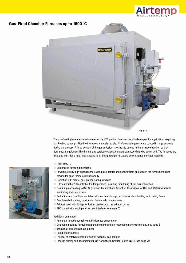
The gas-fired high-temperature furnaces of the HTB product line are specially developed for applications requiring fast heating up ramps. Gas-fired furnaces are preferred also if inflammable gases are produced in large amounts during the process. A large content of the gas emissions are already burned in the furnace chamber, so that downstream equipment like thermal and catalytic exhaust cleaners can accordingly be downsized. The furnaces are insulated with highly heat-resistant and long-life lightweight refractory brick insulation or fiber materials.
Tmax 1600 °CCustomized furnace dimensionsPowerful, sturdy high-speed burners with pulse control and special flame guidance in the furnace chamber provide for good temperature uniformityOperation with natural gas, propane or liquified gasFully automatic PLC control of the temperature, including monitoring of the burner functionGas fittings according to DVGW (German Technical and Scientific Association for Gas and Water) with flame monitoring and safety valveReduction-resistant fiber insulation with low heat storage provides for short heating and cooling timesDouble-walled housing provides for low outside temperaturesExhaust hood with fittings for further discharge of the exhaust gasesPLC control with touch panel as user interface, see page 70
Additional equipmentAutomatic lambda control to set the furnace atmosphereDebinding package for debinding and sintering with corresponding safety technology, see page 6Exhaust air and exhaust gas pipingRecuperator burnersThermal or catalytic exhaust cleaning systems, see page 35Process display and documentation via Nabertherm Control Center (NCC), see page 70
�4
Catalytic and Thermal Afterburning Systems
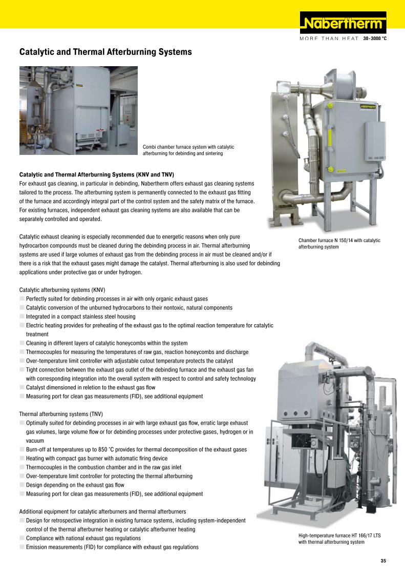
Catalytic and Thermal Afterburning Systems (KNV and TNV)For exhaust gas cleaning, in particular in debinding, Nabertherm offers exhaust gas cleaning systems tailored to the process. The afterburning system is permanently connected to the exhaust gas fitting of the furnace and accordingly integral part of the control system and the safety matrix of the furnace. For existing furnaces, independent exhaust gas cleaning systems are also available that can be separately controlled and operated.
Catalytic exhaust cleaning is especially recommended due to energetic reasons when only pure hydrocarbon compounds must be cleaned during the debinding process in air. Thermal afterburning systems are used if large volumes of exhaust gas from the debinding process in air must be cleaned and/or if there is a risk that the exhaust gases might damage the catalyst. Thermal afterburning is also used for debinding applications under protective gas or under hydrogen.
Catalytic afterburning systems (KNV)Perfectly suited for debinding processes in air with only organic exhaust gasesCatalytic conversion of the unburned hydrocarbons to their nontoxic, natural componentsIntegrated in a compact stainless steel housingElectric heating provides for preheating of the exhaust gas to the optimal reaction temperature for catalytic treatmentCleaning in different layers of catalytic honeycombs within the systemThermocouples for measuring the temperatures of raw gas, reaction honeycombs and dischargeOver-temperature limit controller with adjustable cutout temperature protects the catalystTight connection between the exhaust gas outlet of the debinding furnace and the exhaust gas fan with corresponding integration into the overall system with respect to control and safety technologyCatalyst dimensioned in reletion to the exhaust gas flowMeasuring port for clean gas measurements (FID), see additional equipment
Thermal afterburning systems (TNV)Optimally suited for debinding processes in air with large exhaust gas flow, erratic large exhaust gas volumes, large volume flow or for debinding processes under protective gases, hydrogen or in vacuumBurn-off at temperatures up to 850 °C provides for thermal decomposition of the exhaust gasesHeating with compact gas burner with automatic firing deviceThermocouples in the combustion chamber and in the raw gas inletOver-temperature limit controller for protecting the thermal afterburningDesign depending on the exhaust gas flowMeasuring port for clean gas measurements (FID), see additional equipment
Additional equipment for catalytic afterburners and thermal afterburnersDesign for retrospective integration in existing furnace systems, including system-independent control of the thermal afterburner heating or catalytic afterburner heatingCompliance with national exhaust gas regulationsEmission measurements (FID) for compliance with exhaust gas regulations
High-temperature furnace HT 166/17 LTS with thermal afterburning system
Chamber furnace N 150/14 with catalytic afterburning system
Combi chamber furnace system with catalytic afterburning for debinding and sintering
��
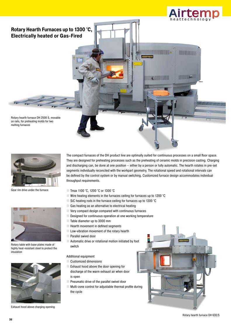
Rotary Hearth Furnaces up to 1�00 °C,Electrically heated or Gas-Fired
Rotary hearth furnace DH 630/S
Gear rim drive under the furnace
Exhaust hood above charging opening
The compact furnaces of the DH product line are optimally suited for continuous processes on a small floor space. They are designed for preheating processes such as the preheating of ceramic molds in precision casting. Charging and discharging can, be done at one position – either by a person or fully automatic. The hearth rotates in pre-set segments individually reconciled with the workpart geometry. The rotational speed and rotational intervals can be defined by the control system or by manual switching. Customized furnace design accommodates individual throughput requirements.
Tmax 1100 °C, 1200 °C or 1300 °C Wire heating elements in the furnaces ceiling for furnaces up to 1200 °CSiC heating rods in the furnace ceiling for furnaces up to 1300 °CGas heating as an alternative to electrical heatingVery compact design compared with continuous furnacesDesigned for continuous operation at one working temperatureTable diameter up to 3000 mmHearth movement in defined segmentsLow-vibration movement of the rotary hearthParallel swivel doorAutomatic drive or rotational motion initiated by foot switch
Additional equipmentCustomized dimensionsExhaust hood above the door opening for discharge of the warm exhaust air when door is openPneumatic drive of the parallel swivel doorMulti-zone control for adjustable thermal profile during the cycle
Rotary table with base plates made of highly heat-resistant steel to protect the insulation
Rotary hearth furnace DH 2500 S, movable on rails, for preheating molds for two melting furnaces
��
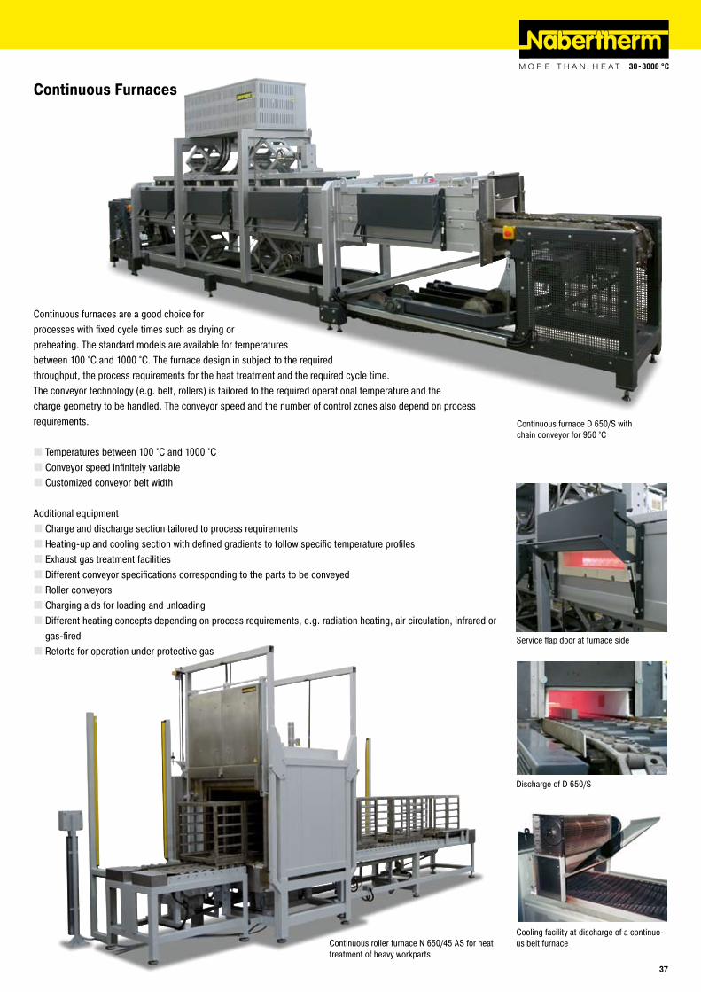
Continuous furnaces are a good choice for processes with fixed cycle times such as drying or preheating. The standard models are available for temperatures between 100 °C and 1000 °C. The furnace design in subject to the required throughput, the process requirements for the heat treatment and the required cycle time. The conveyor technology (e.g. belt, rollers) is tailored to the required operational temperature and the charge geometry to be handled. The conveyor speed and the number of control zones also depend on process requirements.
Temperatures between 100 °C and 1000 °CConveyor speed infinitely variableCustomized conveyor belt width
Additional equipmentCharge and discharge section tailored to process requirementsHeating-up and cooling section with defined gradients to follow specific temperature profilesExhaust gas treatment facilitiesDifferent conveyor specifications corresponding to the parts to be conveyedRoller conveyorsCharging aids for loading and unloadingDifferent heating concepts depending on process requirements, e.g. radiation heating, air circulation, infrared or gas-firedRetorts for operation under protective gas
Continuous furnace D 650/S with chain conveyor for 950 °C
Continuous Furnaces
Service flap door at furnace side
Discharge of D 650/S
Continuous roller furnace N 650/45 AS for heat treatment of heavy workparts
Cooling facility at discharge of a continuo-us belt furnace
��
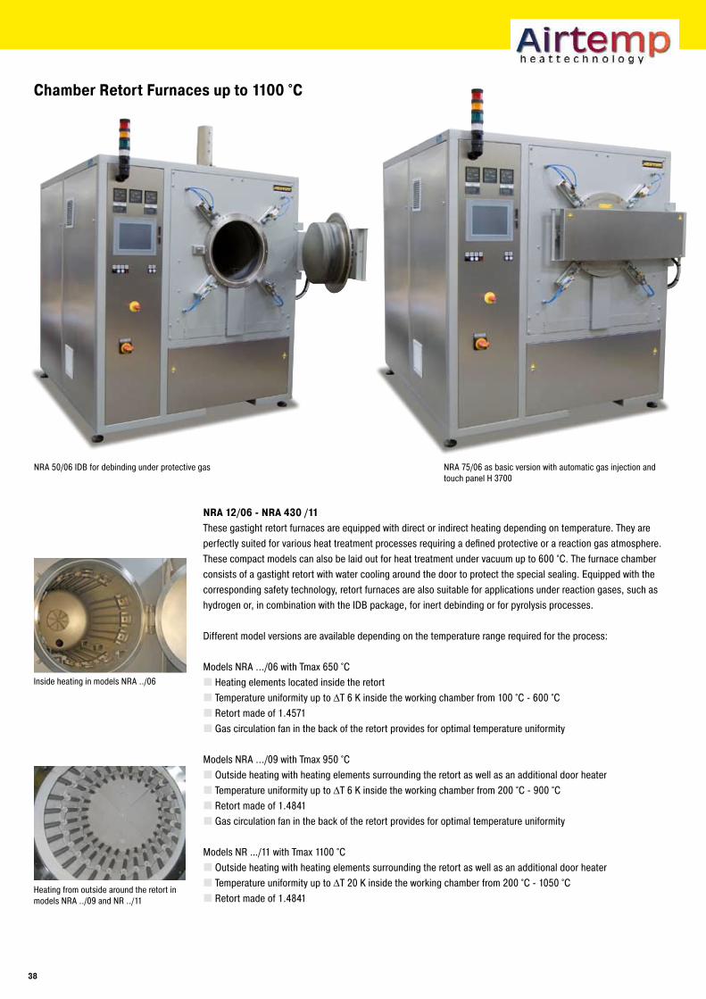
Heating from outside around the retort in models NRA ../09 and NR ../11
NRA 75/06 as basic version with automatic gas injection and touch panel H 3700
NRA 1�/0� - NRA 4�0 /11These gastight retort furnaces are equipped with direct or indirect heating depending on temperature. They are perfectly suited for various heat treatment processes requiring a defined protective or a reaction gas atmosphere. These compact models can also be laid out for heat treatment under vacuum up to 600 °C. The furnace chamber consists of a gastight retort with water cooling around the door to protect the special sealing. Equipped with the corresponding safety technology, retort furnaces are also suitable for applications under reaction gases, such as hydrogen or, in combination with the IDB package, for inert debinding or for pyrolysis processes.
Different model versions are available depending on the temperature range required for the process:
Models NRA .../06 with Tmax 650 °CHeating elements located inside the retortTemperature uniformity up to ΔT 6 K inside the working chamber from 100 °C - 600 °CRetort made of 1.4571Gas circulation fan in the back of the retort provides for optimal temperature uniformity
Models NRA .../09 with Tmax 950 °COutside heating with heating elements surrounding the retort as well as an additional door heaterTemperature uniformity up to ΔT 6 K inside the working chamber from 200 °C - 900 °CRetort made of 1.4841Gas circulation fan in the back of the retort provides for optimal temperature uniformity
Models NR …/11 with Tmax 1100 °COutside heating with heating elements surrounding the retort as well as an additional door heaterTemperature uniformity up to ΔT 20 K inside the working chamber from 200 °C - 1050 °CRetort made of 1.4841
Chamber Retort Furnaces up to 1100 °C
Inside heating in models NRA ../06
NRA 50/06 IDB for debinding under protective gas
�8
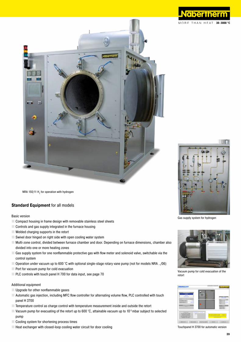
Vacuum pump for cold evacuation of the retort
Touchpanel H 3700 for automatic version
Standard Equipment for all models
Basic versionCompact housing in frame design with removable stainless steel sheetsControls and gas supply integrated in the furnace housingWelded charging supports in the retortSwivel door hinged on right side with open cooling water systemMulti-zone control, divided between furnace chamber and door. Depending on furnace dimensions, chamber also divided into one or more heating zonesGas supply system for one nonflammable protective gas with flow meter and solenoid valve, switchable via the control system Operation under vacuum up to 600 °C with optional single-stage rotary vane pump (not for models NRA ../06)Port for vacuum pump for cold evacuationPLC controls with touch panel H 700 for data input, see page 70
Additional equipmentUpgrade for other nonflammable gasesAutomatic gas injection, including MFC flow controller for alternating volume flow, PLC controlled with touch panel H 3700Temperature control as charge control with temperature measurement inside and outside the retortVacuum pump for evacuating of the retort up to 600 °C, attainable vacuum up to 10-5 mbar subject to selected pumpCooling system for shortening process timesHeat exchanger with closed-loop cooling water circuit for door cooling
Gas supply system for hydrogen
NRA 150/11 H2 for operation with hydrogen
��
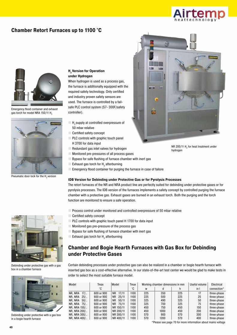
Chamber Retort Furnaces up to 1100 °C
Debinding under protective gas with a gas box in a chamber furnace
Debinding under protective with a gas box in a bogie hearth furnace
Emergency flood container and exhaust gas torch for model NRA 150/11 H2
Pneumatic door lock for the H2 version
NR 200/11 H2 for heat treatment under hydrogen
H� Version for Operation under HydrogenWhen hydrogen is used as a process gas, the furnace is additionally equipped with the required safety technology. Only certified and industry proven safety sensors are used. The furnace is controlled by a fail-safe PLC control system (S7- 300F/safety controller).
H2 supply at controlled overpressure of 50 mbar relativeCertified safety conceptPLC controls with graphic touch panel H 3700 for data inputRedundant gas inlet valves for hydrogenMonitored pre-pressures of all process gasesBypass for safe flushing of furnace chamber with inert gasExhaust gas torch for H2 afterburningEmergency flood container for purging the furnace in case of failore
IDB Version for Debinding under Protective Gas or for Pyrolysis ProcessesThe retort furnaces of the NR and NRA product line are perfectly suited for debinding under protective gases or for pyrolysis processes. The IDB version of the furnaces implements a safety concept by controlled purging the furnace chamber with a protective gas. Exhaust gases are burned in an exhaust torch. Both the purging and the torch function are monitored to ensure a safe operation.
Process control under monitored and controlled overpressure of 50 mbar relativeCertified safety conceptPLC controls with graphic touch panel H 1700 for data inputMonitored gas pre-pressure of the process gasBypass for safe flushing of furnace chamber with inert gasExhaust gas torch for H2 afterburning
Chamber and Bogie Hearth Furnaces with Gas Box for Debinding under Protective Gases
Certain debinding processes under protective gas can also be realized in a chamber or bogie hearth furnace with inserted gas box as a cost-effective alternative. In our state-of-the-art test center we would be glad to make tests in order to select the most suitable furnace model.
Model Tmax Model Tmax Working chamber dimensions in mm Useful volume Electrical°C °C w d h in l connection*
NR, NRA 17/.. 600 or 900 NR 17/11 1100 225 350 225 17 three-phaseNR, NRA 25/.. 600 or 900 NR 25/11 1100 225 500 225 25 three-phaseNR, NRA 50/.. 600 or 900 NR 50/11 1100 325 490 325 50 three-phaseNR, NRA 75/.. 600 or 900 NR 75/11 1100 325 700 325 75 three-phaseNR, NRA 150/.. 600 or 900 NR 150/11 1100 450 750 450 150 three-phaseNR, NRA 200/.. 600 or 900 NR 200/11 1100 450 1000 450 200 three-phaseNR, NRA 300/.. 600 or 900 NR 300/11 1100 570 900 570 300 three-phaseNR, NRA 400/.. 600 or 900 NR 400/11 1100 570 1200 570 400 three-phase
*Please see page 70 for more information about mains voltage
40
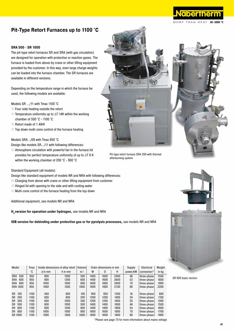
Pit-Type Retort Furnaces up to 1100 °C
SRA �00 - SR 1000The pit-type retort furnaces SR and SRA (with gas circulation) are designed for operation with protective or reaction gases. The furnace is loaded from above by crane or other lifting equipment provided by the customer. In this way, even large charge weights can be loaded into the furnace chamber. The SR furnaces are available in different versions.
Depending on the temperature range in which the furnace be used, the following models are available:
Models SR .../11 with Tmax 1100 °CFour-side heating outside the retort Temperature uniformity up to ΔT 14K within the working chamber of 500 °C - 1100 °CRetort made of 1.4841Top down multi-zone control of the furnace heating
Models SRA ../09 with Tmax 950 °CDesign like models SR…/11 with following differences:
Atmosphere circulation with powerful fan in the furnace lid provides for perfect temperature uniformity of up to ΔT 8 K within the working chamber of 200 °C - 900 °C
Standard Equipment (all models)Design like standard equipment of models NR and NRA with following differences:
Charging from above with crane or other lifting equipment from customerHinged lid with opening to the side and with cooling waterMulti-zone control of the furnace heating from the top down
Additional equipment, see models NR and NRA
H� version for operation under hydrogen, see models NR and NRA
IDB version for debinding under protective gas or for pyrolysis processes, see models NR and NRA
Pit-type retort furnace SRA 200 with thermal afterburning system
Model Tmax Inside dimensions of alloy retort Volume Outer dimensions in mm Supply Electrical Weight°C Ø in mm h in mm in l W D H power/kW connection* in kg
SRA 500 950 800 1000 500 1400 1600 2400 46 three-phase 1500SRA 600 950 800 1200 600 1400 1600 2600 52 three-phase 1600SRA 800 950 1000 1000 800 1600 1800 2400 70 three-phase 1900SRA 1000 950 1000 1300 1000 1600 1800 2700 90 three-phase 2200
SR 100 1100 450 600 100 950 950 1200 16 three-phase 800SR 200 1100 600 800 200 1200 1200 1400 24 three-phase 1100SR 300 1100 600 1000 300 1200 1200 1600 35 three-phase 1300SR 500 1100 800 1000 500 1400 1400 1600 46 three-phase 1500SR 600 1100 800 1200 600 1400 1400 1800 54 three-phase 1600SR 800 1100 1000 1000 800 1600 1600 1600 70 three-phase 1700SR 1000 1100 1000 1300 1000 1600 1600 1900 90 three-phase 1900
*Please see page 70 for more information about mains voltage
SR 600 basic version
41
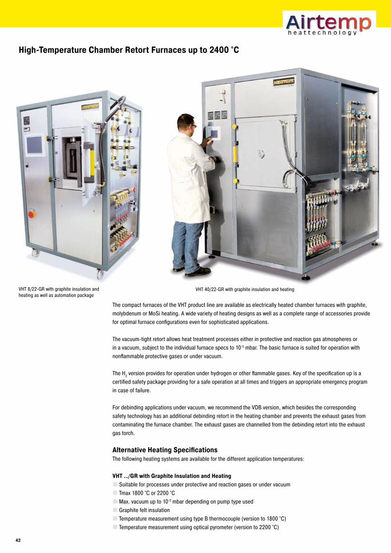
The compact furnaces of the VHT product line are available as electrically heated chamber furnaces with graphite, molybdenum or MoSi heating. A wide variety of heating designs as well as a complete range of accessories provide for optimal furnace configurations even for sophisticated applications.
The vacuum-tight retort allows heat treatment processes either in protective and reaction gas atmospheres or in a vacuum, subject to the individual furnace specs to 10-5 mbar. The basic furnace is suited for operation with nonflammable protective gases or under vacuum.
The H2 version provides for operation under hydrogen or other flammable gases. Key of the specification up is a certified safety package providing for a safe operation at all times and triggers an appropriate emergency program in case of failure.
For debinding applications under vacuum, we recommend the VDB version, which besides the corresponding safety technology has an additional debinding retort in the heating chamber and prevents the exhaust gases from contaminating the furnace chamber. The exhaust gases are channelled from the debinding retort into the exhaust gas torch.
Alternative Heating SpecificationsThe following heating systems are available for the different application temperatures:
VHT ../GR with Graphite Insulation and HeatingSuitable for processes under protective and reaction gases or under vacuumTmax 1800 °C or 2200 °CMax. vacuum up to 10-2 mbar depending on pump type usedGraphite felt insulationTemperature measurement using type B thermocouple (version to 1800 °C)Temperature measurement using optical pyrometer (version to 2200 °C)
High-Temperature Chamber Retort Furnaces up to �400 °C
VHT 8/22-GR with graphite insulation and heating as well as automation package
VHT 40/22-GR with graphite insulation and heating
4�
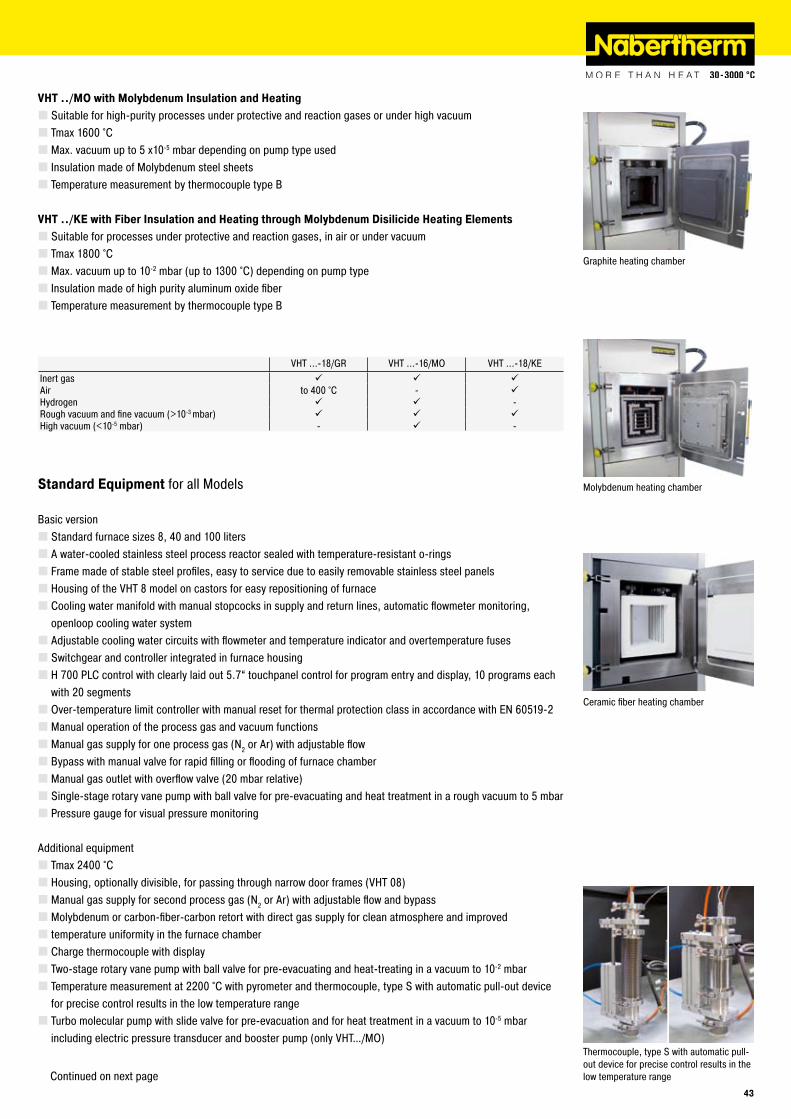
Graphite heating chamber
Ceramic fiber heating chamber
Molybdenum heating chamber
VHT ../MO with Molybdenum Insulation and HeatingSuitable for high-purity processes under protective and reaction gases or under high vacuumTmax 1600 °CMax. vacuum up to 5 x10⁻⁵ mbar depending on pump type usedInsulation made of Molybdenum steel sheetsTemperature measurement by thermocouple type B
VHT ../KE with Fiber Insulation and Heating through Molybdenum Disilicide Heating ElementsSuitable for processes under protective and reaction gases, in air or under vacuumTmax 1800 °CMax. vacuum up to 10-2 mbar (up to 1300 °C) depending on pump typeInsulation made of high purity aluminum oxide fiberTemperature measurement by thermocouple type B
VHT ...-18/GR VHT ...-16/MO VHT ...-18/KEInert gas Air to 400 °C - Hydrogen -Rough vacuum and fine vacuum (>10-3 mbar) High vacuum (<10-5 mbar) - -
Standard Equipment for all Models
Basic versionStandard furnace sizes 8, 40 and 100 litersA water-cooled stainless steel process reactor sealed with temperature-resistant o-ringsFrame made of stable steel profiles, easy to service due to easily removable stainless steel panelsHousing of the VHT 8 model on castors for easy repositioning of furnaceCooling water manifold with manual stopcocks in supply and return lines, automatic flowmeter monitoring, openloop cooling water systemAdjustable cooling water circuits with flowmeter and temperature indicator and overtemperature fusesSwitchgear and controller integrated in furnace housingH 700 PLC control with clearly laid out 5.7“ touchpanel control for program entry and display, 10 programs each with 20 segmentsOver-temperature limit controller with manual reset for thermal protection class in accordance with EN 60519-2Manual operation of the process gas and vacuum functionsManual gas supply for one process gas (N2 or Ar) with adjustable flowBypass with manual valve for rapid filling or flooding of furnace chamberManual gas outlet with overflow valve (20 mbar relative)Single-stage rotary vane pump with ball valve for pre-evacuating and heat treatment in a rough vacuum to 5 mbarPressure gauge for visual pressure monitoring
Additional equipmentTmax 2400 °CHousing, optionally divisible, for passing through narrow door frames (VHT 08)Manual gas supply for second process gas (N2 or Ar) with adjustable flow and bypassMolybdenum or carbon-fiber-carbon retort with direct gas supply for clean atmosphere and improvedtemperature uniformity in the furnace chamberCharge thermocouple with displayTwo-stage rotary vane pump with ball valve for pre-evacuating and heat-treating in a vacuum to 10-2 mbarTemperature measurement at 2200 °C with pyrometer and thermocouple, type S with automatic pull-out device for precise control results in the low temperature rangeTurbo molecular pump with slide valve for pre-evacuation and for heat treatment in a vacuum to 10-5 mbar including electric pressure transducer and booster pump (only VHT…/MO)
Continued on next page
Thermocouple, type S with automatic pull-out device for precise control results in the low temperature range
4�
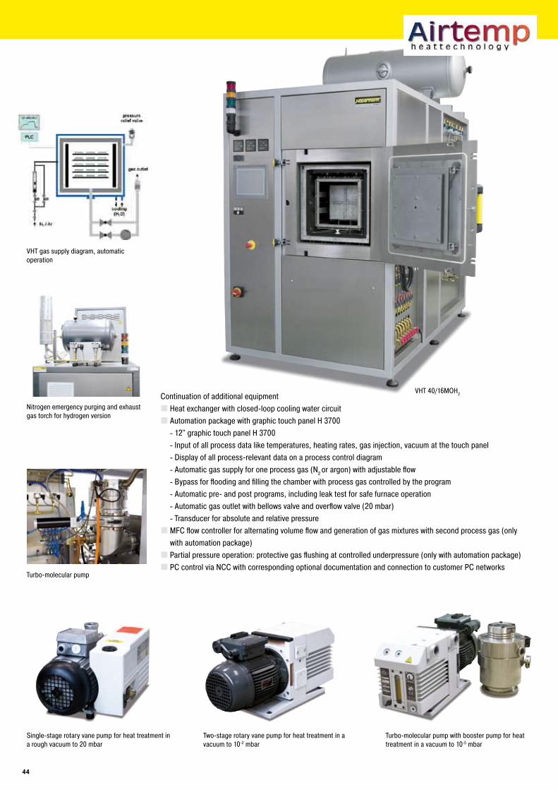
VHT 40/16MOH2
Single-stage rotary vane pump for heat treatment in a rough vacuum to 20 mbar
VHT gas supply diagram, automatic operation
Two-stage rotary vane pump for heat treatment in a vacuum to 10-2 mbar
Turbo-molecular pump with booster pump for heat treatment in a vacuum to 10-5 mbar
Nitrogen emergency purging and exhaust gas torch for hydrogen version
Heat exchanger with closed-loop cooling water circuitAutomation package with graphic touch panel H 3700
12" graphic touch panel H 3700Input of all process data like temperatures, heating rates, gas injection, vacuum at the touch panelDisplay of all process-relevant data on a process control diagramAutomatic gas supply for one process gas (N2 or argon) with adjustable flowBypass for flooding and filling the chamber with process gas controlled by the programAutomatic pre- and post programs, including leak test for safe furnace operationAutomatic gas outlet with bellows valve and overflow valve (20 mbar)Transducer for absolute and relative pressure
MFC flow controller for alternating volume flow and generation of gas mixtures with second process gas (only with automation package)Partial pressure operation: protective gas flushing at controlled underpressure (only with automation package)PC control via NCC with corresponding optional documentation and connection to customer PC networks
--------
Continuation of additional equipment
Turbo-molecular pump
44
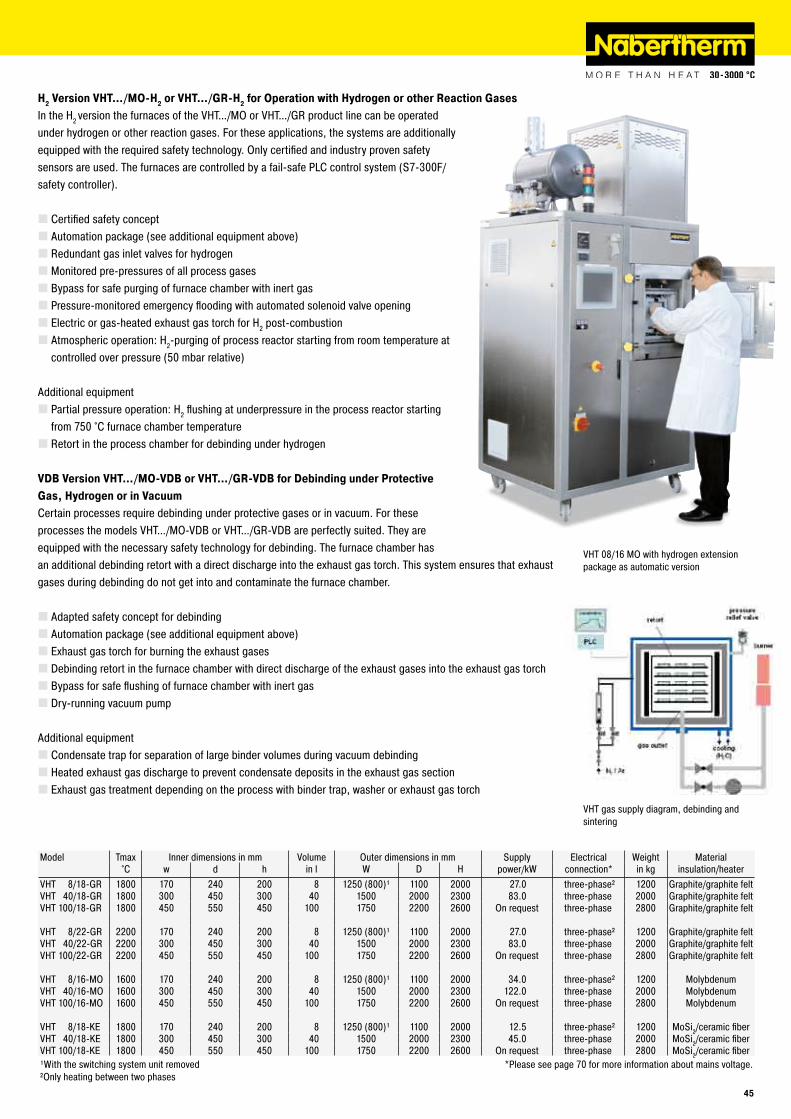
VHT gas supply diagram, debinding and sintering
VHT 08/16 MO with hydrogen extension package as automatic version
Model Tmax Inner dimensions in mm Volume Outer dimensions in mm Supply Electrical Weight Material°C w d h in l W D H power/kW connection* in kg insulation/heater
VHT 8/18-GR 1800 170 240 200 8 1250 (800)¹ 1100 2000 27.0 three-phase² 1200 Graphite/graphite feltVHT 40/18-GR 1800 300 450 300 40 1500 2000 2300 83.0 three-phase 2000 Graphite/graphite feltVHT 100/18-GR 1800 450 550 450 100 1750 2200 2600 On request three-phase 2800 Graphite/graphite felt
VHT 8/22-GR 2200 170 240 200 8 1250 (800)¹ 1100 2000 27.0 three-phase² 1200 Graphite/graphite feltVHT 40/22-GR 2200 300 450 300 40 1500 2000 2300 83.0 three-phase 2000 Graphite/graphite feltVHT 100/22-GR 2200 450 550 450 100 1750 2200 2600 On request three-phase 2800 Graphite/graphite felt
VHT 8/16-MO 1600 170 240 200 8 1250 (800)¹ 1100 2000 34.0 three-phase² 1200 MolybdenumVHT 40/16-MO 1600 300 450 300 40 1500 2000 2300 122.0 three-phase 2000 MolybdenumVHT 100/16-MO 1600 450 550 450 100 1750 2200 2600 On request three-phase 2800 Molybdenum
VHT 8/18-KE 1800 170 240 200 8 1250 (800)¹ 1100 2000 12.5 three-phase² 1200 MoSi2/ceramic fiberVHT 40/18-KE 1800 300 450 300 40 1500 2000 2300 45.0 three-phase 2000 MoSi2/ceramic fiberVHT 100/18-KE 1800 450 550 450 100 1750 2200 2600 On request three-phase 2800 MoSi2/ceramic fiber¹With the switching system unit removed *Please see page 70 for more information about mains voltage.²Only heating between two phases
H� Version VHT…/MO-H� or VHT…/GR-H� for Operation with Hydrogen or other Reaction GasesIn the H2 version the furnaces of the VHT…/MO or VHT…/GR product line can be operated under hydrogen or other reaction gases. For these applications, the systems are additionally equipped with the required safety technology. Only certified and industry proven safety sensors are used. The furnaces are controlled by a fail-safe PLC control system (S7-300F/safety controller).
Certified safety conceptAutomation package (see additional equipment above)Redundant gas inlet valves for hydrogenMonitored pre-pressures of all process gasesBypass for safe purging of furnace chamber with inert gasPressure-monitored emergency flooding with automated solenoid valve openingElectric or gas-heated exhaust gas torch for H2 post-combustionAtmospheric operation: H2-purging of process reactor starting from room temperature at controlled over pressure (50 mbar relative)
Additional equipmentPartial pressure operation: H2 flushing at underpressure in the process reactor starting from 750 °C furnace chamber temperatureRetort in the process chamber for debinding under hydrogen
VDB Version VHT…/MO-VDB or VHT…/GR-VDB for Debinding under Protective Gas, Hydrogen or in Vacuum Certain processes require debinding under protective gases or in vacuum. For these processes the models VHT…/MO-VDB or VHT…/GR-VDB are perfectly suited. They are equipped with the necessary safety technology for debinding. The furnace chamber has an additional debinding retort with a direct discharge into the exhaust gas torch. This system ensures that exhaust gases during debinding do not get into and contaminate the furnace chamber.
Adapted safety concept for debindingAutomation package (see additional equipment above)Exhaust gas torch for burning the exhaust gasesDebinding retort in the furnace chamber with direct discharge of the exhaust gases into the exhaust gas torchBypass for safe flushing of furnace chamber with inert gasDry-running vacuum pump
Additional equipmentCondensate trap for separation of large binder volumes during vacuum debindingHeated exhaust gas discharge to prevent condensate deposits in the exhaust gas sectionExhaust gas treatment depending on the process with binder trap, washer or exhaust gas torch
4�
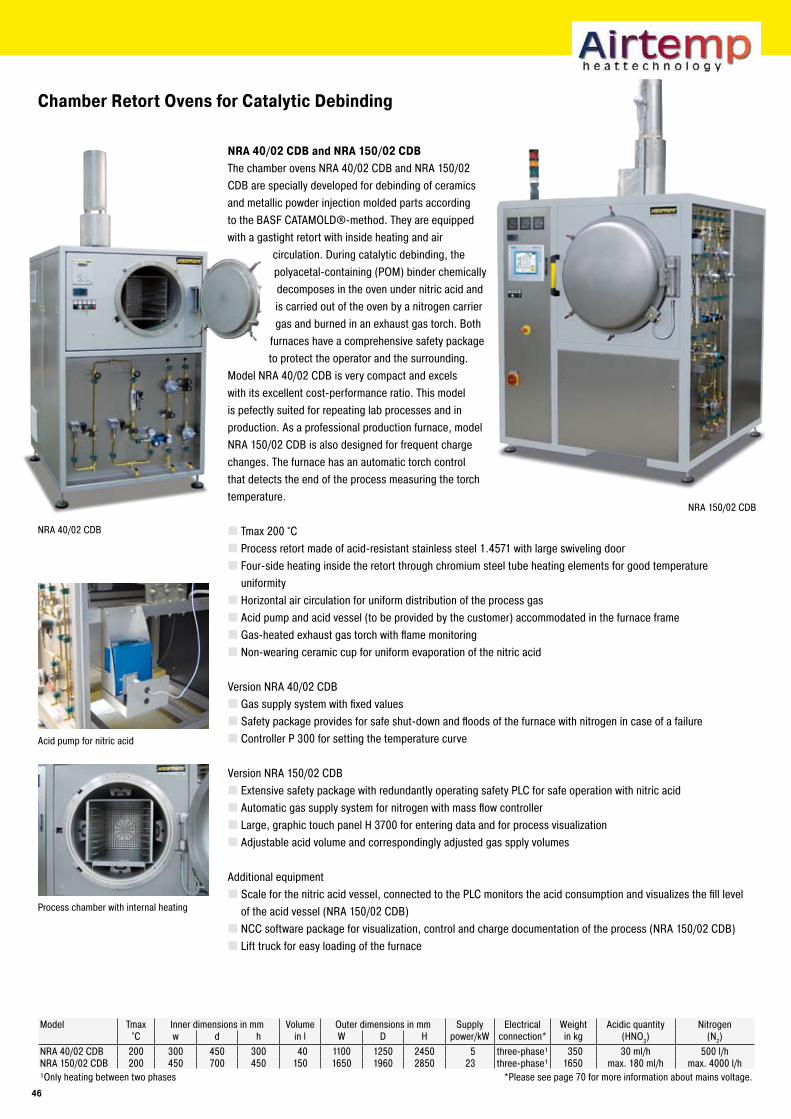
NRA 150/02 CDB
NRA 40/02 CDB
Chamber Retort Ovens for Catalytic Debinding
NRA 40/0� CDB and NRA 1�0/0� CDBThe chamber ovens NRA 40/02 CDB and NRA 150/02 CDB are specially developed for debinding of ceramics and metallic powder injection molded parts according to the BASF CATAMOLD®-method. They are equipped with a gastight retort with inside heating and air
circulation. During catalytic debinding, the polyacetal-containing (POM) binder chemically decomposes in the oven under nitric acid and is carried out of the oven by a nitrogen carrier gas and burned in an exhaust gas torch. Both
furnaces have a comprehensive safety package to protect the operator and the surrounding.
Model NRA 40/02 CDB is very compact and excels with its excellent cost-performance ratio. This model is pefectly suited for repeating lab processes and in production. As a professional production furnace, model NRA 150/02 CDB is also designed for frequent charge changes. The furnace has an automatic torch control that detects the end of the process measuring the torch temperature.
Tmax 200 °CProcess retort made of acid-resistant stainless steel 1.4571 with large swiveling doorFour-side heating inside the retort through chromium steel tube heating elements for good temperature uniformityHorizontal air circulation for uniform distribution of the process gasAcid pump and acid vessel (to be provided by the customer) accommodated in the furnace frameGas-heated exhaust gas torch with flame monitoringNon-wearing ceramic cup for uniform evaporation of the nitric acid
Version NRA 40/02 CDBGas supply system with fixed valuesSafety package provides for safe shut-down and floods of the furnace with nitrogen in case of a failureController P 300 for setting the temperature curve
Version NRA 150/02 CDBExtensive safety package with redundantly operating safety PLC for safe operation with nitric acidAutomatic gas supply system for nitrogen with mass flow controllerLarge, graphic touch panel H 3700 for entering data and for process visualizationAdjustable acid volume and correspondingly adjusted gas spply volumes
Additional equipment Scale for the nitric acid vessel, connected to the PLC monitors the acid consumption and visualizes the fill level of the acid vessel (NRA 150/02 CDB)NCC software package for visualization, control and charge documentation of the process (NRA 150/02 CDB)Lift truck for easy loading of the furnace
Acid pump for nitric acid
Process chamber with internal heating
Model Tmax Inner dimensions in mm Volume Outer dimensions in mm Supply Electrical Weight Acidic quantity Nitrogen°C w d h in l W D H power/kW connection* in kg (HNO3) (N2)
NRA 40/02 CDB 200 300 450 300 40 1100 1250 2450 5 three-phase¹ 350 30 ml/h 500 l/hNRA 150/02 CDB 200 450 700 450 150 1650 1960 2850 23 three-phase¹ 1650 max. 180 ml/h max. 4000 l/h¹Only heating between two phases *Please see page 70 for more information about mains voltage.
4�
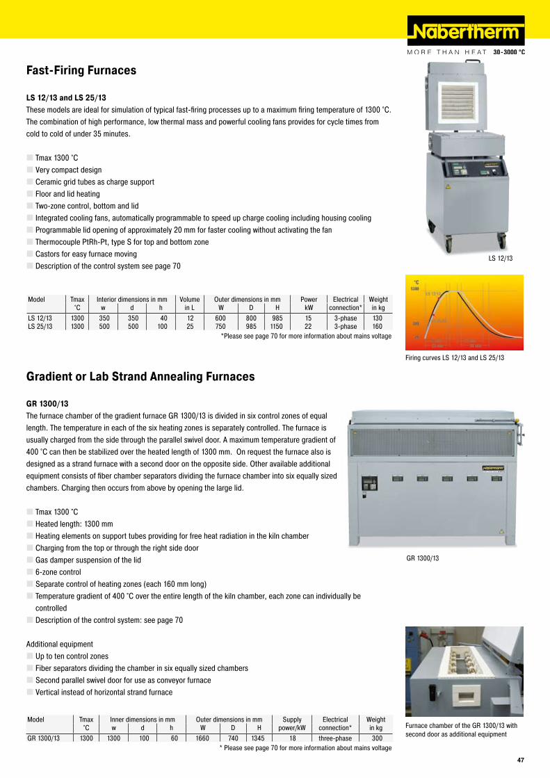
GR 1300/13
LS 12/13
Fast-Firing Furnaces
LS 1�/1� and LS ��/1�These models are ideal for simulation of typical fast-firing processes up to a maximum firing temperature of 1300 °C.The combination of high performance, low thermal mass and powerful cooling fans provides for cycle times fromcold to cold of under 35 minutes.
Tmax 1300 °CVery compact designCeramic grid tubes as charge supportFloor and lid heatingTwo-zone control, bottom and lidIntegrated cooling fans, automatically programmable to speed up charge cooling including housing coolingProgrammable lid opening of approximately 20 mm for faster cooling without activating the fanThermocouple PtRh-Pt, type S for top and bottom zoneCastors for easy furnace movingDescription of the control system see page 70
Model Tmax Interior dimensions in mm Volume Outer dimensions in mm Power Electrical Weight°C w d h in L W D H kW connection* in kg
LS 12/13 1300 350 350 40 12 600 800 985 15 3-phase 130LS 25/13 1300 500 500 100 25 750 985 1150 22 3-phase 160
*Please see page 70 for more information about mains voltage
Firing curves LS 12/13 and LS 25/13
Gradient or Lab Strand Annealing Furnaces
Furnace chamber of the GR 1300/13 with second door as additional equipment
GR 1�00/1�The furnace chamber of the gradient furnace GR 1300/13 is divided in six control zones of equal length. The temperature in each of the six heating zones is separately controlled. The furnace is usually charged from the side through the parallel swivel door. A maximum temperature gradient of 400 °C can then be stabilized over the heated length of 1300 mm. On request the furnace also is designed as a strand furnace with a second door on the opposite side. Other available additional equipment consists of fiber chamber separators dividing the furnace chamber into six equally sized chambers. Charging then occurs from above by opening the large lid.
Tmax 1300 °CHeated length: 1300 mmHeating elements on support tubes providing for free heat radiation in the kiln chamberCharging from the top or through the right side doorGas damper suspension of the lid6-zone controlSeparate control of heating zones (each 160 mm long)Temperature gradient of 400 °C over the entire length of the kiln chamber, each zone can individually be controlledDescription of the control system: see page 70
Additional equipmentUp to ten control zonesFiber separators dividing the chamber in six equally sized chambersSecond parallel swivel door for use as conveyor furnaceVertical instead of horizontal strand furnace
Model Tmax Inner dimensions in mm Outer dimensions in mm Supply Electrical Weight°C w d h W D H power/kW connection* in kg
GR 1300/13 1300 1300 100 60 1660 740 1345 18 three-phase 300* Please see page 70 for more information about mains voltage
4�
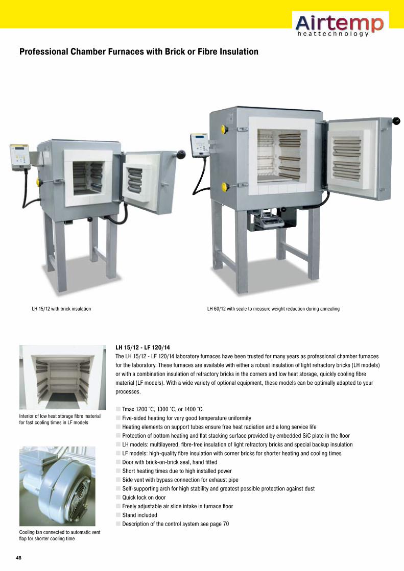
Professional Chamber Furnaces with Brick or Fibre Insulation
LH 1�/1� - LF 1�0/14The LH 15/12 - LF 120/14 laboratory furnaces have been trusted for many years as professional chamber furnaces for the laboratory. These furnaces are available with either a robust insulation of light refractory bricks (LH models) or with a combination insulation of refractory bricks in the corners and low heat storage, quickly cooling fibre material (LF models). With a wide variety of optional equipment, these models can be optimally adapted to your processes.
Tmax 1200 °C, 1300 °C, or 1400 °CFive-sided heating for very good temperature uniformityHeating elements on support tubes ensure free heat radiation and a long service lifeProtection of bottom heating and flat stacking surface provided by embedded SiC plate in the floorLH models: multilayered, fibre-free insulation of light refractory bricks and special backup insulationLF models: high-quality fibre insulation with corner bricks for shorter heating and cooling timesDoor with brick-on-brick seal, hand fittedShort heating times due to high installed powerSide vent with bypass connection for exhaust pipeSelf-supporting arch for high stability and greatest possible protection against dustQuick lock on doorFreely adjustable air slide intake in furnace floorStand includedDescription of the control system see page 70
Interior of low heat storage fibre material for fast cooling times in LF models
Cooling fan connected to automatic vent flap for shorter cooling time
LH 15/12 with brick insulation LH 60/12 with scale to measure weight reduction during annealing
48
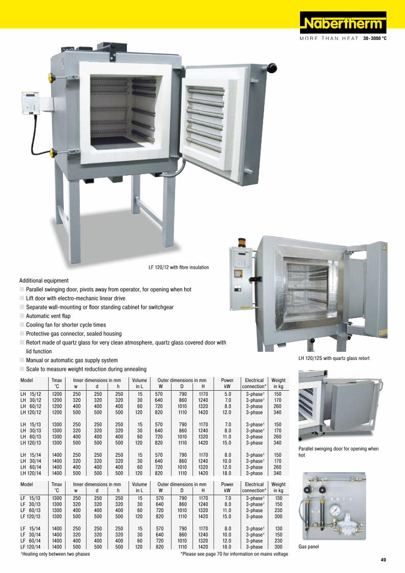
Parallel swinging door for opening whenhot
LF 120/12 with fibre insulation
Additional equipmentParallel swinging door, pivots away from operator, for opening when hotLift door with electro-mechanic linear driveSeparate wall-mounting or floor standing cabinet for switchgearAutomatic vent flapCooling fan for shorter cycle timesProtective gas connector, sealed housingRetort made of quartz glass for very clean atmosphere, quartz glass covered door with lid functionManual or automatic gas supply systemScale to measure weight reduction during annealing
Model Tmax Inner dimensions in mm Volume Outer dimensions in mm Power Electrical Weight°C w d h in L W D H kW connection* in kg
LH 15/12 1200 250 250 250 15 570 790 1170 5.0 3-phase¹ 150LH 30/12 1200 320 320 320 30 640 860 1240 7.0 3-phase¹ 170LH 60/12 1200 400 400 400 60 720 1010 1320 8.0 3-phase 260LH 120/12 1200 500 500 500 120 820 1110 1420 12.0 3-phase 340
LH 15/13 1300 250 250 250 15 570 790 1170 7.0 3-phase¹ 150LH 30/13 1300 320 320 320 30 640 860 1240 8.0 3-phase¹ 170LH 60/13 1300 400 400 400 60 720 1010 1320 11.0 3-phase 260LH 120/13 1300 500 500 500 120 820 1110 1420 15.0 3-phase 340
LH 15/14 1400 250 250 250 15 570 790 1170 8.0 3-phase¹ 150LH 30/14 1400 320 320 320 30 640 860 1240 10.0 3-phase¹ 170LH 60/14 1400 400 400 400 60 720 1010 1320 12.0 3-phase 260LH 120/14 1400 500 500 500 120 820 1110 1420 18.0 3-phase 340
Model Tmax Inner dimensions in mm Volume Outer dimensions in mm Power Electrical Weight°C w d h in L W D H kW connection* in kg
LF 15/13 1300 250 250 250 15 570 790 1170 7.0 3-phase¹ 130LF 30/13 1300 320 320 320 30 640 860 1240 8.0 3-phase¹ 150LF 60/13 1300 400 400 400 60 720 1010 1320 11.0 3-phase 230LF 120/13 1300 500 500 500 120 820 1110 1420 15.0 3-phase 300
LF 15/14 1400 250 250 250 15 570 790 1170 8.0 3-phase¹ 130LF 30/14 1400 320 320 320 30 640 860 1240 10.0 3-phase¹ 150LF 60/14 1400 400 400 400 60 720 1010 1320 12.0 3-phase 230LF 120/14 1400 500 500 500 120 820 1110 1420 18.0 3-phase 300¹Heating only between two phases *Please see page 70 for information on mains voltage
Gas panel
LH 120/12S with quartz glass retort
4�
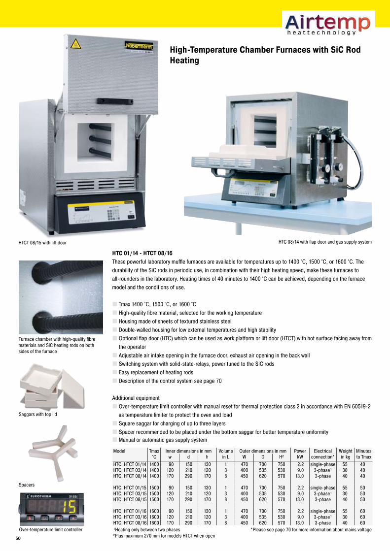
High-Temperature Chamber Furnaces with SiC Rod Heating
HTC 01/14 - HTCT 08/1�These powerful laboratory muffle furnaces are available for temperatures up to 1400 °C, 1500 °C, or 1600 °C. The durability of the SiC rods in periodic use, in combination with their high heating speed, make these furnaces to all-rounders in the laboratory. Heating times of 40 minutes to 1400 °C can be achieved, depending on the furnace model and the conditions of use.
Tmax 1400 °C, 1500 °C, or 1600 °CHigh-quality fibre material, selected for the working temperatureHousing made of sheets of textured stainless steelDouble-walled housing for low external temperatures and high stabilityOptional flap door (HTC) which can be used as work platform or lift door (HTCT) with hot surface facing away from the operatorAdjustable air intake opening in the furnace door, exhaust air opening in the back wallSwitching system with solid-state-relays, power tuned to the SiC rodsEasy replacement of heating rodsDescription of the control system see page 70
Additional equipmentOver-temperature limit controller with manual reset for thermal protection class 2 in accordance with EN 60519-2 as temperature limiter to protect the oven and loadSquare saggar for charging of up to three layersSpacer recommended to be placed under the bottom saggar for better temperature uniformityManual or automatic gas supply system
Furnace chamber with high-quality fibre materials and SiC heating rods on both sides of the furnace
Model Tmax Inner dimensions in mm Volume Outer dimensions in mm Power Electrical Weight Minutes°C w d h in L W D H² kW connection* in kg to Tmax
HTC, HTCT 01/14 1400 90 150 130 1 470 700 750 2.2 single-phase 55 40HTC, HTCT 03/14 1400 120 210 120 3 400 535 530 9.0 3-phase¹ 30 40HTC, HTCT 08/14 1400 170 290 170 8 450 620 570 13.0 3-phase 40 40
HTC, HTCT 01/15 1500 90 150 130 1 470 700 750 2.2 single-phase 55 50HTC, HTCT 03/15 1500 120 210 120 3 400 535 530 9.0 3-phase¹ 30 50HTC, HTCT 08/15 1500 170 290 170 8 450 620 570 13.0 3-phase 40 50
HTC, HTCT 01/16 1600 90 150 130 1 470 700 750 2.2 single-phase 55 60HTC, HTCT 03/16 1600 120 210 120 3 400 535 530 9.0 3-phase¹ 30 60HTC, HTCT 08/16 1600 170 290 170 8 450 620 570 13.0 3-phase 40 60¹Heating only between two phases *Please see page 70 for more information about mains voltage²Plus maximum 270 mm for models HTCT when open
Over-temperature limit controller
HTC 08/14 with flap door and gas supply system
Saggars with top lid
HTCT 08/15 with lift door
Spacers
�0
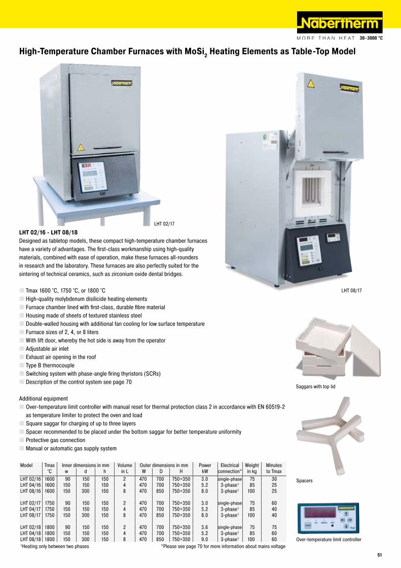
LHT 08/17
LHT 02/17
High-Temperature Chamber Furnaces with MoSi� Heating Elements as Table-Top Model
LHT 0�/1� - LHT 08/18Designed as tabletop models, these compact high-temperature chamber furnaces have a variety of advantages. The first-class workmanship using high-quality materials, combined with ease of operation, make these furnaces all-rounders in research and the laboratory. These furnaces are also perfectly suited for the sintering of technical ceramics, such as zirconium oxide dental bridges.
Tmax 1600 °C, 1750 °C, or 1800 °CHigh-quality molybdenum disilicide heating elementsFurnace chamber lined with first-class, durable fibre materialHousing made of sheets of textured stainless steelDouble-walled housing with additional fan cooling for low surface temperatureFurnace sizes of 2, 4, or 8 litersWith lift door, whereby the hot side is away from the operatorAdjustable air inletExhaust air opening in the roofType B thermocoupleSwitching system with phase-angle firing thyristors (SCRs)Description of the control system see page 70
Additional equipmentOver-temperature limit controller with manual reset for thermal protection class 2 in accordance with EN 60519-2 as temperature limiter to protect the oven and loadSquare saggar for charging of up to three layersSpacer recommended to be placed under the bottom saggar for better temperature uniformityProtective gas connectionManual or automatic gas supply system
Model Tmax Inner dimensions in mm Volume Outer dimensions in mm Power Electrical Weight Minutes°C w d h in L W D H kW connection* in kg to Tmax
LHT 02/16 1600 90 150 150 2 470 700 750+350 3.0 single-phase 75 30LHT 04/16 1600 150 150 150 4 470 700 750+350 5.2 3-phase¹ 85 25LHT 08/16 1600 150 300 150 8 470 850 750+350 8.0 3-phase¹ 100 25
LHT 02/17 1750 90 150 150 2 470 700 750+350 3.0 single-phase 75 60LHT 04/17 1750 150 150 150 4 470 700 750+350 5.2 3-phase¹ 85 40LHT 08/17 1750 150 300 150 8 470 850 750+350 8.0 3-phase¹ 100 40
LHT 02/18 1800 90 150 150 2 470 700 750+350 3.6 single-phase 75 75LHT 04/18 1800 150 150 150 4 470 700 750+350 5.2 3-phase¹ 85 60LHT 08/18 1800 150 300 150 8 470 850 750+350 9.0 3-phase¹ 100 60¹Heating only between two phases *Please see page 70 for more information about mains voltage
Over-temperature limit controller
Saggars with top lid
Spacers
�1
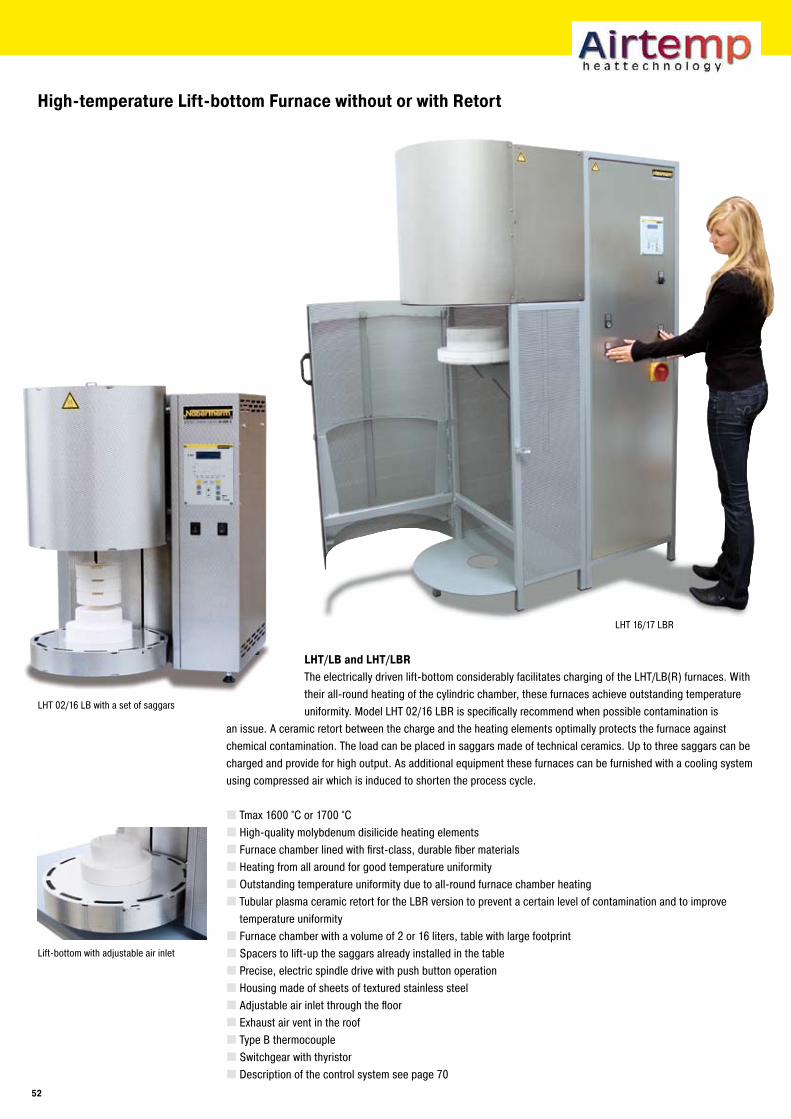
LHT 16/17 LBR
High-temperature Lift-bottom Furnace without or with Retort
LHT/LB and LHT/LBRThe electrically driven lift-bottom considerably facilitates charging of the LHT/LB(R) furnaces. With their all-round heating of the cylindric chamber, these furnaces achieve outstanding temperature uniformity. Model LHT 02/16 LBR is specifically recommend when possible contamination is
an issue. A ceramic retort between the charge and the heating elements optimally protects the furnace against chemical contamination. The load can be placed in saggars made of technical ceramics. Up to three saggars can be charged and provide for high output. As additional equipment these furnaces can be furnished with a cooling system using compressed air which is induced to shorten the process cycle.
Tmax 1600 °C or 1700 °CHigh-quality molybdenum disilicide heating elementsFurnace chamber lined with first-class, durable fiber materialsHeating from all around for good temperature uniformityOutstanding temperature uniformity due to all-round furnace chamber heatingTubular plasma ceramic retort for the LBR version to prevent a certain level of contamination and to improve temperature uniformityFurnace chamber with a volume of 2 or 16 liters, table with large footprintSpacers to lift-up the saggars already installed in the tablePrecise, electric spindle drive with push button operationHousing made of sheets of textured stainless steelAdjustable air inlet through the floorExhaust air vent in the roofType B thermocoupleSwitchgear with thyristorDescription of the control system see page 70
Lift-bottom with adjustable air inlet
LHT 02/16 LB with a set of saggars
��
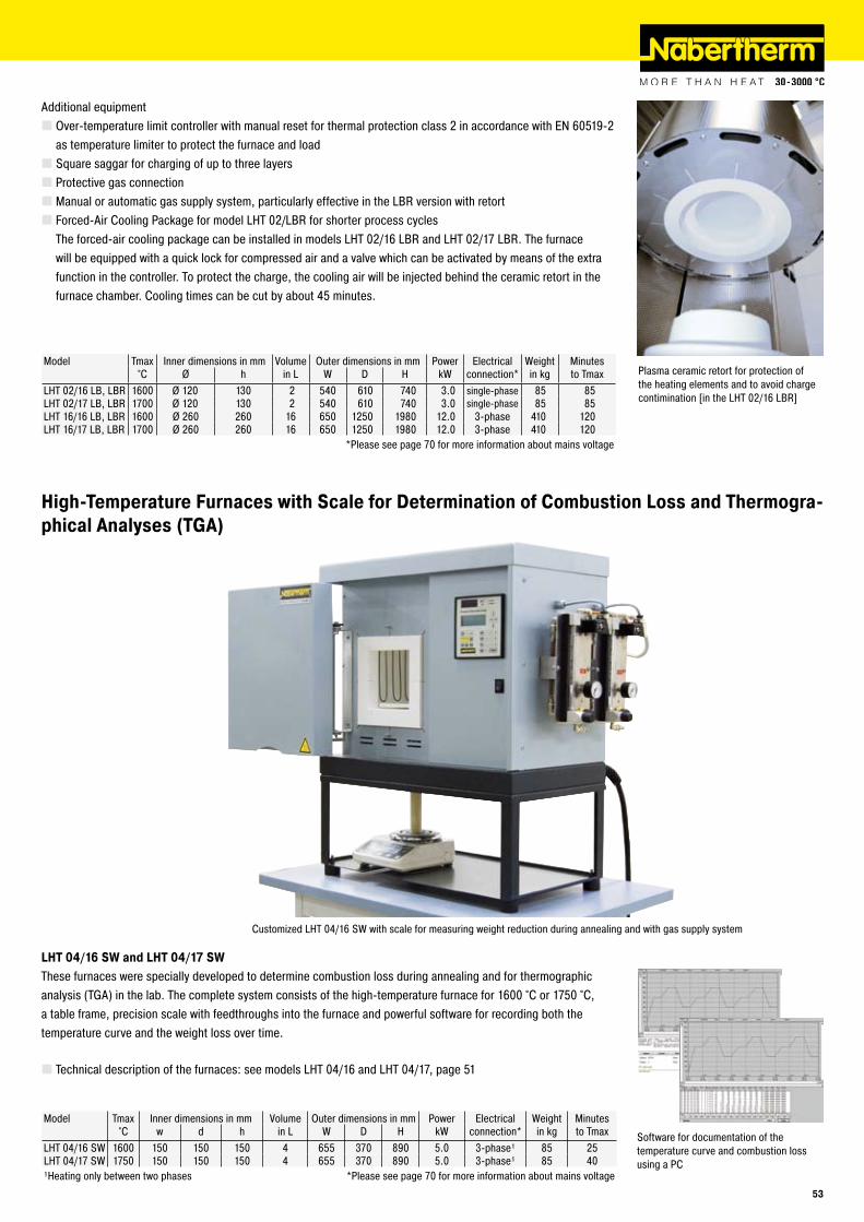
Model Tmax Inner dimensions in mm Volume Outer dimensions in mm Power Electrical Weight Minutes°C Ø h in L W D H kW connection* in kg to Tmax
LHT 02/16 LB, LBR 1600 Ø 120 130 2 540 610 740 3.0 single-phase 85 85LHT 02/17 LB, LBR 1700 Ø 120 130 2 540 610 740 3.0 single-phase 85 85LHT 16/16 LB, LBR 1600 Ø 260 260 16 650 1250 1980 12.0 3-phase 410 120LHT 16/17 LB, LBR 1700 Ø 260 260 16 650 1250 1980 12.0 3-phase 410 120
*Please see page 70 for more information about mains voltage
Plasma ceramic retort for protection of the heating elements and to avoid charge contimination [in the LHT 02/16 LBR]
Additional equipmentOver-temperature limit controller with manual reset for thermal protection class 2 in accordance with EN 60519-2 as temperature limiter to protect the furnace and loadSquare saggar for charging of up to three layersProtective gas connectionManual or automatic gas supply system, particularly effective in the LBR version with retortForced-Air Cooling Package for model LHT 02/LBR for shorter process cycles The forced-air cooling package can be installed in models LHT 02/16 LBR and LHT 02/17 LBR. The furnace will be equipped with a quick lock for compressed air and a valve which can be activated by means of the extra function in the controller. To protect the charge, the cooling air will be injected behind the ceramic retort in the furnace chamber. Cooling times can be cut by about 45 minutes.
Customized LHT 04/16 SW with scale for measuring weight reduction during annealing and with gas supply system
Software for documentation of the temperature curve and combustion loss using a PC
High-Temperature Furnaces with Scale for Determination of Combustion Loss and Thermogra-phical Analyses (TGA)
LHT 04/1� SW and LHT 04/1� SWThese furnaces were specially developed to determine combustion loss during annealing and for thermographic analysis (TGA) in the lab. The complete system consists of the high-temperature furnace for 1600 °C or 1750 °C, a table frame, precision scale with feedthroughs into the furnace and powerful software for recording both the temperature curve and the weight loss over time.
Technical description of the furnaces: see models LHT 04/16 and LHT 04/17, page 51
Model Tmax Inner dimensions in mm Volume Outer dimensions in mm Power Electrical Weight Minutes°C w d h in L W D H kW connection* in kg to Tmax
LHT 04/16 SW 1600 150 150 150 4 655 370 890 5.0 3-phase¹ 85 25LHT 04/17 SW 1750 150 150 150 4 655 370 890 5.0 3-phase¹ 85 40¹Heating only between two phases *Please see page 70 for more information about mains voltage
��
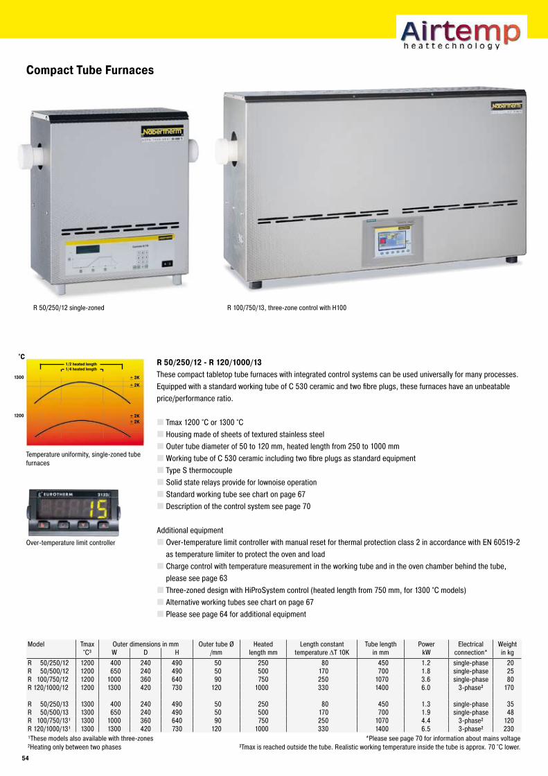
°C
1�00
1�00+ �K+ �K
+ �K
+ �K
Compact Tube Furnaces
R �0/��0/1� - R 1�0/1000/1�These compact tabletop tube furnaces with integrated control systems can be used universally for many processes. Equipped with a standard working tube of C 530 ceramic and two fibre plugs, these furnaces have an unbeatable price/performance ratio.
Tmax 1200 °C or 1300 °CHousing made of sheets of textured stainless steelOuter tube diameter of 50 to 120 mm, heated length from 250 to 1000 mmWorking tube of C 530 ceramic including two fibre plugs as standard equipmentType S thermocoupleSolid state relays provide for lownoise operationStandard working tube see chart on page 67Description of the control system see page 70
Additional equipmentOver-temperature limit controller with manual reset for thermal protection class 2 in accordance with EN 60519-2 as temperature limiter to protect the oven and loadCharge control with temperature measurement in the working tube and in the oven chamber behind the tube, please see page 63Three-zoned design with HiProSystem control (heated length from 750 mm, for 1300 °C models)Alternative working tubes see chart on page 67Please see page 64 for additional equipment
Temperature uniformity, single-zoned tube furnaces
R 100/750/13, three-zone control with H100R 50/250/12 single-zoned
Model Tmax Outer dimensions in mm Outer tube Ø Heated Length constant Tube length Power Electrical Weight°C³ W D H /mm length mm temperature ΔT 10K in mm kW connection* in kg
R 50/250/12 1200 400 240 490 50 250 80 450 1.2 single-phase 20R 50/500/12 1200 650 240 490 50 500 170 700 1.8 single-phase 25R 100/750/12 1200 1000 360 640 90 750 250 1070 3.6 single-phase 80R 120/1000/12 1200 1300 420 730 120 1000 330 1400 6.0 3-phase² 170
R 50/250/13 1300 400 240 490 50 250 80 450 1.3 single-phase 35R 50/500/13 1300 650 240 490 50 500 170 700 1.9 single-phase 48R 100/750/13¹ 1300 1000 360 640 90 750 250 1070 4.4 3-phase² 120R 120/1000/13¹ 1300 1300 420 730 120 1000 330 1400 6.5 3-phase² 230¹These models also available with three-zones *Please see page 70 for information about mains voltage²Heating only between two phases ³Tmax is reached outside the tube. Realistic working temperature inside the tube is approx. 70 °C lower.
Over-temperature limit controller
1/� heated length1/4 heated length
�4
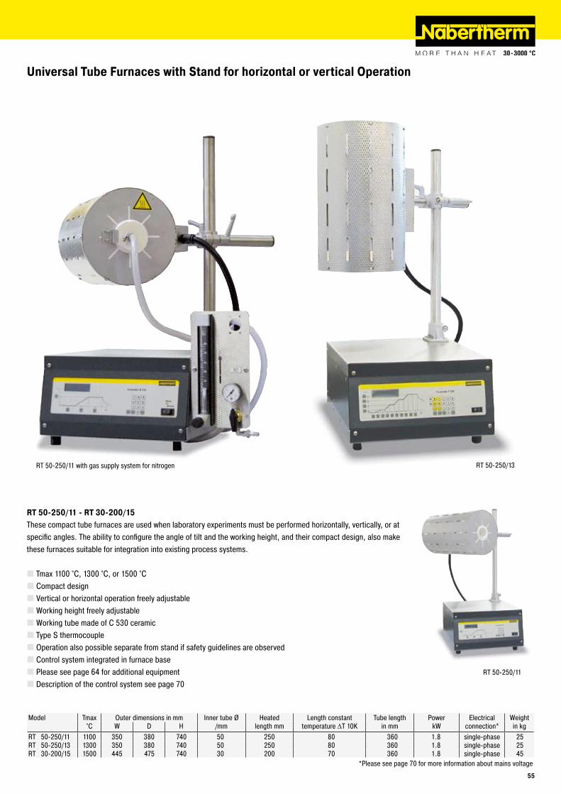
RT 50-250/11
RT 50-250/13
Universal Tube Furnaces with Stand for horizontal or vertical Operation
RT �0-��0/11 - RT �0-�00/1�These compact tube furnaces are used when laboratory experiments must be performed horizontally, vertically, or at specific angles. The ability to configure the angle of tilt and the working height, and their compact design, also make these furnaces suitable for integration into existing process systems.
Tmax 1100 °C, 1300 °C, or 1500 °CCompact designVertical or horizontal operation freely adjustableWorking height freely adjustableWorking tube made of C 530 ceramicType S thermocoupleOperation also possible separate from stand if safety guidelines are observedControl system integrated in furnace basePlease see page 64 for additional equipmentDescription of the control system see page 70
Model Tmax Outer dimensions in mm Inner tube Ø Heated Length constant Tube length Power Electrical Weight°C W D H /mm length mm temperature ΔT 10K in mm kW connection* in kg
RT 50-250/11 1100 350 380 740 50 250 80 360 1.8 single-phase 25RT 50-250/13 1300 350 380 740 50 250 80 360 1.8 single-phase 25RT 30-200/15 1500 445 475 740 30 200 70 360 1.8 single-phase 45
*Please see page 70 for more information about mains voltage
RT 50-250/11 with gas supply system for nitrogen
��
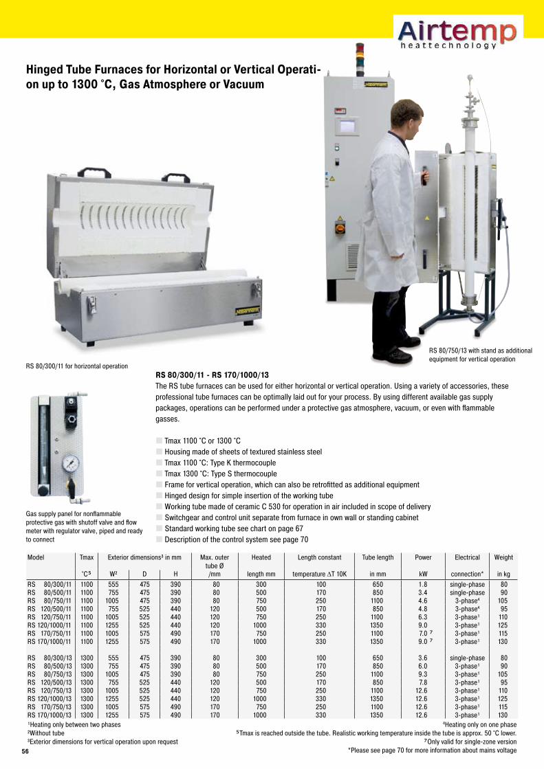
Hinged Tube Furnaces for Horizontal or Vertical Operati-on up to 1�00 °C, Gas Atmosphere or Vacuum
RS 80/300/11 for horizontal operation
RS 80/750/13 with stand as additional equipment for vertical operation
RS 80/�00/11 - RS 1�0/1000/1�The RS tube furnaces can be used for either horizontal or vertical operation. Using a variety of accessories, these professional tube furnaces can be optimally laid out for your process. By using different available gas supply packages, operations can be performed under a protective gas atmosphere, vacuum, or even with flammable gasses.
Tmax 1100 °C or 1300 °CHousing made of sheets of textured stainless steelTmax 1100 °C: Type K thermocoupleTmax 1300 °C: Type S thermocoupleFrame for vertical operation, which can also be retrofitted as additional equipmentHinged design for simple insertion of the working tubeWorking tube made of ceramic C 530 for operation in air included in scope of deliverySwitchgear and control unit separate from furnace in own wall or standing cabinetStandard working tube see chart on page 67Description of the control system see page 70
Model Tmax Exterior dimensions³ in mm Max. outer tube Ø
Heated Length constant Tube length Power Electrical Weight
°C� W² D H /mm length mm temperature ΔT 10K in mm kW connection* in kgRS 80/300/11 1100 555 475 390 80 300 100 650 1.8 single-phase 80RS 80/500/11 1100 755 475 390 80 500 170 850 3.4 single-phase 90RS 80/750/11 1100 1005 475 390 80 750 250 1100 4.6 3-phase4 105RS 120/500/11 1100 755 525 440 120 500 170 850 4.8 3-phase4 95RS 120/750/11 1100 1005 525 440 120 750 250 1100 6.3 3-phase¹ 110RS 120/1000/11 1100 1255 525 440 120 1000 330 1350 9.0 3-phase¹ 125RS 170/750/11 1100 1005 575 490 170 750 250 1100 7.0 � 3-phase¹ 115RS 170/1000/11 1100 1255 575 490 170 1000 330 1350 9.0 � 3-phase¹ 130
RS 80/300/13 1300 555 475 390 80 300 100 650 3.6 single-phase 80RS 80/500/13 1300 755 475 390 80 500 170 850 6.0 3-phase¹ 90RS 80/750/13 1300 1005 475 390 80 750 250 1100 9.3 3-phase¹ 105RS 120/500/13 1300 755 525 440 120 500 170 850 7.8 3-phase¹ 95RS 120/750/13 1300 1005 525 440 120 750 250 1100 12.6 3-phase¹ 110RS 120/1000/13 1300 1255 525 440 120 1000 330 1350 12.6 3-phase¹ 125RS 170/750/13 1300 1005 575 490 170 750 250 1100 12.6 3-phase¹ 115RS 170/1000/13 1300 1255 575 490 170 1000 330 1350 12.6 3-phase¹ 130¹Heating only between two phases 4Heating only on one phase²Without tube �Tmax is reached outside the tube. Realistic working temperature inside the tube is approx. 50 °C lower.³Exterior dimensions for vertical operation upon request �Only valid for single-zone version
*Please see page 70 for more information about mains voltage
Gas supply panel for nonflammable protective gas with shutoff valve and flow meter with regulator valve, piped and ready to connect
��
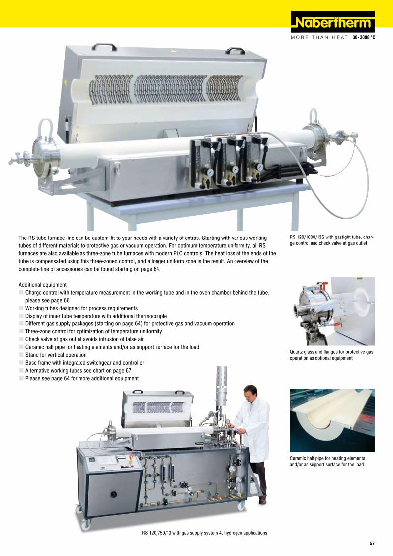
RS 120/1000/13S with gastight tube, char-ge control and check valve at gas outlet
Quartz glass and flanges for protective gas operation as optional equipment
The RS tube furnace line can be custom-fit to your needs with a variety of extras. Starting with various working tubes of different materials to protective gas or vacuum operation. For optimum temperature uniformity, all RS furnaces are also available as three-zone tube furnaces with modern PLC controls. The heat loss at the ends of the tube is compensated using this three-zoned control, and a longer uniform zone is the result. An overview of the complete line of accessories can be found starting on page 64.
Additional equipmentCharge control with temperature measurement in the working tube and in the oven chamber behind the tube, please see page 66Working tubes designed for process requirementsDisplay of inner tube temperature with additional thermocoupleDifferent gas supply packages (starting on page 64) for protective gas and vacuum operationThree-zone control for optimization of temperature uniformityCheck valve at gas outlet avoids intrusion of false airCeramic half pipe for heating elements and/or as support surface for the loadStand for vertical operationBase frame with integrated switchgear and controllerAlternative working tubes see chart on page 67Please see page 64 for more additional equipment
Ceramic half pipe for heating elements and/or as support surface for the load
RS 120/750/13 with gas supply system 4, hydrogen applications
��
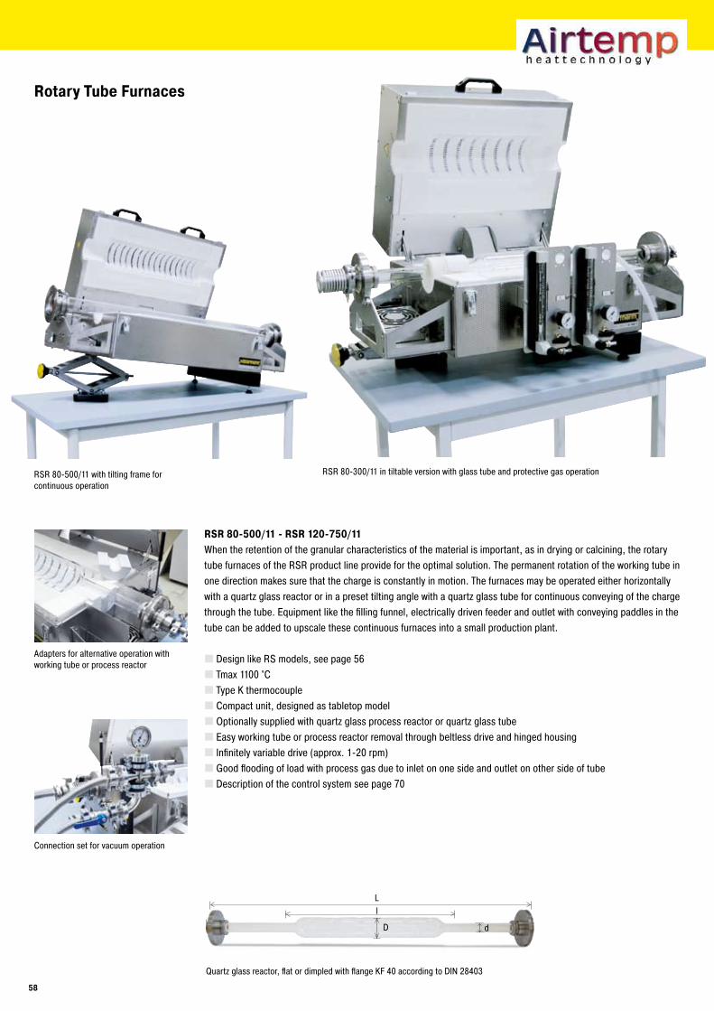
Ll
D d
Rotary Tube Furnaces
RSR 80-500/11 - RSR 120-750/11
When the retention of the granular characteristics of the material is important, as in drying or calcining, the rotary tube furnaces of the RSR product line provide for the optimal solution. The permanent rotation of the working tube in one direction makes sure that the charge is constantly in motion. The furnaces may be operated either horizontally with a quartz glass reactor or in a preset tilting angle with a quartz glass tube for continuous conveying of the charge through the tube. Equipment like the filling funnel, electrically driven feeder and outlet with conveying paddles in the tube can be added to upscale these continuous furnaces into a small production plant.
Design like RS models, see page 56Tmax 1100 °CType K thermocoupleCompact unit, designed as tabletop modelOptionally supplied with quartz glass process reactor or quartz glass tubeEasy working tube or process reactor removal through beltless drive and hinged housingInfinitely variable drive (approx. 1-20 rpm)Good flooding of load with process gas due to inlet on one side and outlet on other side of tubeDescription of the control system see page 70
Adapters for alternative operation with working tube or process reactor
Quartz glass reactor, flat or dimpled with flange KF 40 according to DIN 28403
RSR 80-300/11 in tiltable version with glass tube and protective gas operationRSR 80-500/11 with tilting frame for continuous operation
Connection set for vacuum operation
�8
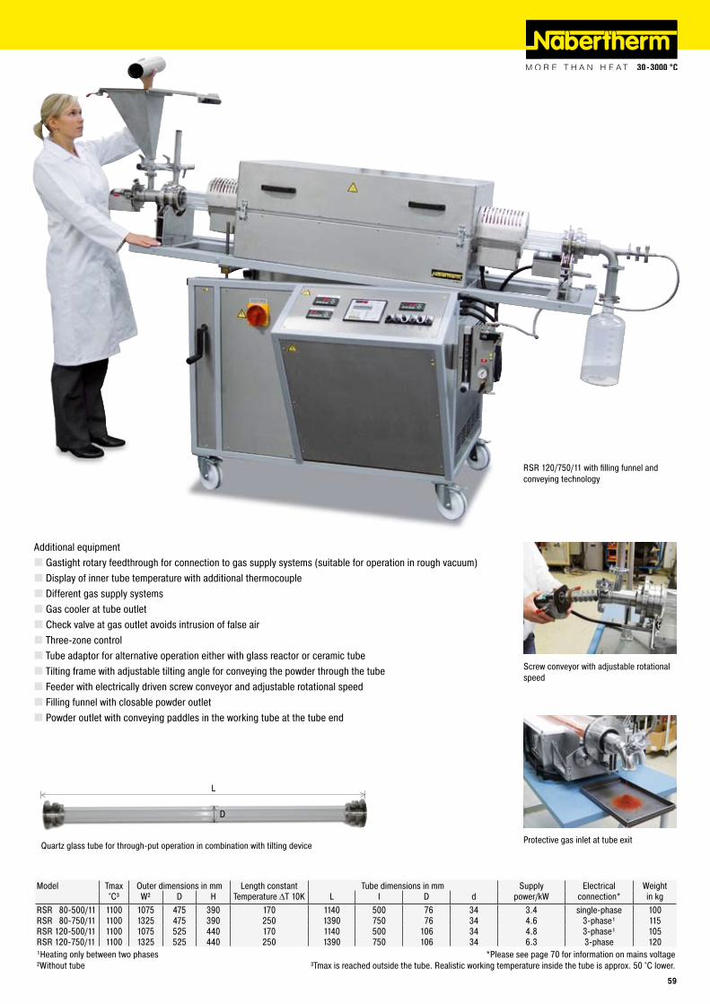
L
D
Quartz glass tube for through-put operation in combination with tilting device
Model Tmax Outer dimensions in mm Length constant Tube dimensions in mm Supply Electrical Weight°C³ W² D H Temperature ΔT 10K L I D d power/kW connection* in kg
RSR 80-500/11 1100 1075 475 390 170 1140 500 76 34 3.4 single-phase 100RSR 80-750/11 1100 1325 475 390 250 1390 750 76 34 4.6 3-phase¹ 115RSR 120-500/11 1100 1075 525 440 170 1140 500 106 34 4.8 3-phase¹ 105RSR 120-750/11 1100 1325 525 440 250 1390 750 106 34 6.3 3-phase 120¹Heating only between two phases *Please see page 70 for information on mains voltage²Without tube ³Tmax is reached outside the tube. Realistic working temperature inside the tube is approx. 50 °C lower.
Screw conveyor with adjustable rotational speed
Protective gas inlet at tube exit
RSR 120/750/11 with filling funnel and conveying technology
Additional equipmentGastight rotary feedthrough for connection to gas supply systems (suitable for operation in rough vacuum)Display of inner tube temperature with additional thermocoupleDifferent gas supply systemsGas cooler at tube outletCheck valve at gas outlet avoids intrusion of false airThree-zone controlTube adaptor for alternative operation either with glass reactor or ceramic tubeTilting frame with adjustable tilting angle for conveying the powder through the tubeFeeder with electrically driven screw conveyor and adjustable rotational speedFilling funnel with closable powder outletPowder outlet with conveying paddles in the working tube at the tube end
��
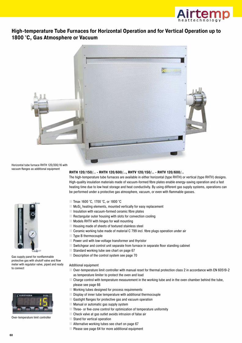
High-temperature Tube Furnaces for Horizontal Operation and for Vertical Operation up to 1800 °C, Gas Atmosphere or Vacuum
RHTH 1�0/1�0/.. - RHTH 1�0/�00/.., RHTV 1�0/1�0/.. - RHTV 1�0/�00/..The high-temperature tube furnaces are available in either horizontal (type RHTH) or vertical (type RHTV) designs. High-quality insulation materials made of vacuum-formed fibre plates enable energy-saving operation and a fast heating time due to low heat storage and heat conductivity. By using different gas supply systems, operations can be performed under a protective gas atmosphere, vacuum, or even with flammable gasses.
Tmax 1600 °C, 1700 °C, or 1800 °CMoSi2 heating elements, mounted vertically for easy replacementInsulation with vacuum-formed ceramic fibre platesRectangular outer housing with slots for convection coolingModels RHTV with hinges for wall mountingHousing made of sheets of textured stainless steelCeramic working tube made of material C 799 incl. fibre plugs operation under airType B thermocouplePower unit with low-voltage transformer and thyristorSwitchgear and control unit separate from furnace in separate floor standing cabinetStandard working tube see chart on page 67Description of the control system see page 70
Additional equipmentOver-temperature limit controller with manual reset for thermal protection class 2 in accordance with EN 60519-2 as temperature limiter to protect the oven and loadCharge control with temperature measurement in the working tube and in the oven chamber behind the tube, please see page 66Working tubes designed for process requirementsDisplay of inner tube temperature with additional thermocoupleGastight flanges for protective gas and vacuum operationManual or automatic gas supply systemThree- or five-zone control for optimization of temperature uniformityCheck valve at gas outlet avoids intrusion of false airStand for vertical operationAlternative working tubes see chart on page 67Please see page 64 for more additional equipment
Horizontal tube furnace RHTH 120/300/16 with vacuum flanges as additional equipment
Over-temperature limit controller
Gas supply panel for nonflammable protective gas with shutoff valve and flow meter with regulator valve, piped and ready to connect
�0
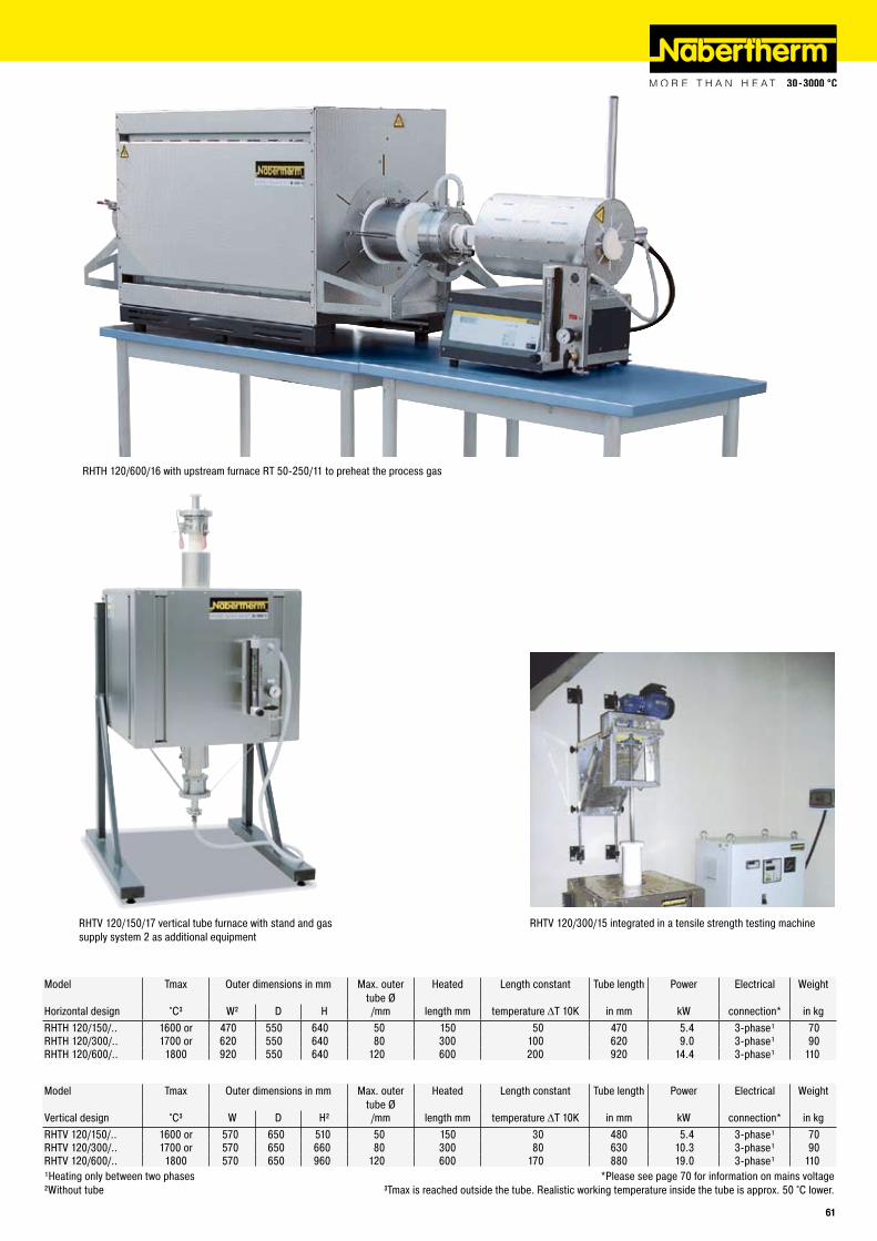
RHTV 120/150/17 vertical tube furnace with stand and gas supply system 2 as additional equipment
Model Tmax Outer dimensions in mm Max. outer tube Ø
Heated Length constant Tube length Power Electrical Weight
Horizontal design °C³ W² D H /mm length mm temperature ΔT 10K in mm kW connection* in kgRHTH 120/150/.. 1600 or 470 550 640 50 150 50 470 5.4 3-phase¹ 70RHTH 120/300/.. 1700 or 620 550 640 80 300 100 620 9.0 3-phase¹ 90RHTH 120/600/.. 1800 920 550 640 120 600 200 920 14.4 3-phase¹ 110
Model Tmax Outer dimensions in mm Max. outer tube Ø
Heated Length constant Tube length Power Electrical Weight
Vertical design °C³ W D H² /mm length mm temperature ΔT 10K in mm kW connection* in kgRHTV 120/150/.. 1600 or 570 650 510 50 150 30 480 5.4 3-phase¹ 70RHTV 120/300/.. 1700 or 570 650 660 80 300 80 630 10.3 3-phase¹ 90RHTV 120/600/.. 1800 570 650 960 120 600 170 880 19.0 3-phase¹ 110¹Heating only between two phases *Please see page 70 for information on mains voltage²Without tube ³Tmax is reached outside the tube. Realistic working temperature inside the tube is approx. 50 °C lower.
RHTV 120/300/15 integrated in a tensile strength testing machine
RHTH 120/600/16 with upstream furnace RT 50-250/11 to preheat the process gas
�1
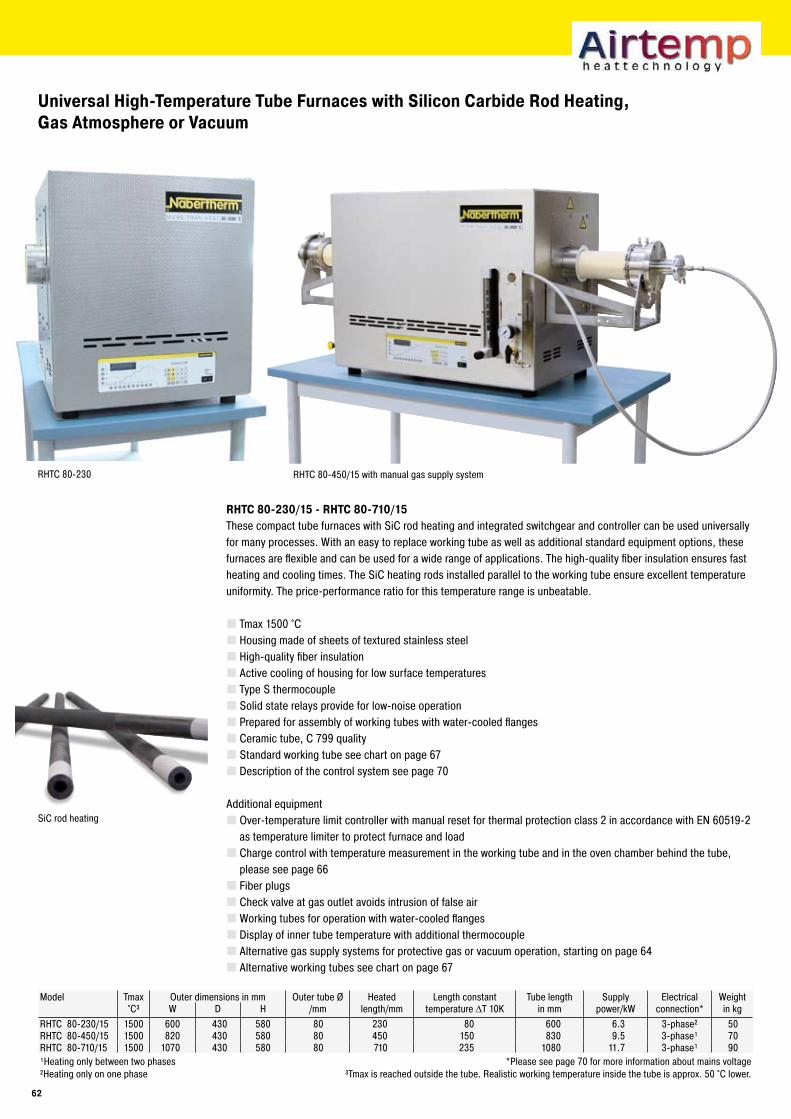
RHTC 80-230
Universal High-Temperature Tube Furnaces with Silicon Carbide Rod Heating,Gas Atmosphere or Vacuum
RHTC 80-��0/1� - RHTC 80-�10/1�These compact tube furnaces with SiC rod heating and integrated switchgear and controller can be used universally for many processes. With an easy to replace working tube as well as additional standard equipment options, these furnaces are flexible and can be used for a wide range of applications. The high-quality fiber insulation ensures fast heating and cooling times. The SiC heating rods installed parallel to the working tube ensure excellent temperature uniformity. The price-performance ratio for this temperature range is unbeatable.
Tmax 1500 °CHousing made of sheets of textured stainless steelHigh-quality fiber insulationActive cooling of housing for low surface temperaturesType S thermocoupleSolid state relays provide for low-noise operationPrepared for assembly of working tubes with water-cooled flangesCeramic tube, C 799 qualityStandard working tube see chart on page 67Description of the control system see page 70
Additional equipmentOver-temperature limit controller with manual reset for thermal protection class 2 in accordance with EN 60519-2 as temperature limiter to protect furnace and loadCharge control with temperature measurement in the working tube and in the oven chamber behind the tube, please see page 66Fiber plugsCheck valve at gas outlet avoids intrusion of false airWorking tubes for operation with water-cooled flangesDisplay of inner tube temperature with additional thermocoupleAlternative gas supply systems for protective gas or vacuum operation, starting on page 64Alternative working tubes see chart on page 67
SiC rod heating
Model Tmax Outer dimensions in mm Outer tube Ø Heated Length constant Tube length Supply Electrical Weight°C³ W D H /mm length/mm temperature ΔT 10K in mm power/kW connection* in kg
RHTC 80-230/15 1500 600 430 580 80 230 80 600 6.3 3-phase² 50RHTC 80-450/15 1500 820 430 580 80 450 150 830 9.5 3-phase¹ 70RHTC 80-710/15 1500 1070 430 580 80 710 235 1080 11.7 3-phase¹ 90¹Heating only between two phases *Please see page 70 for more information about mains voltage²Heating only on one phase ³Tmax is reached outside the tube. Realistic working temperature inside the tube is approx. 50 °C lower.
RHTC 80-450/15 with manual gas supply system
��
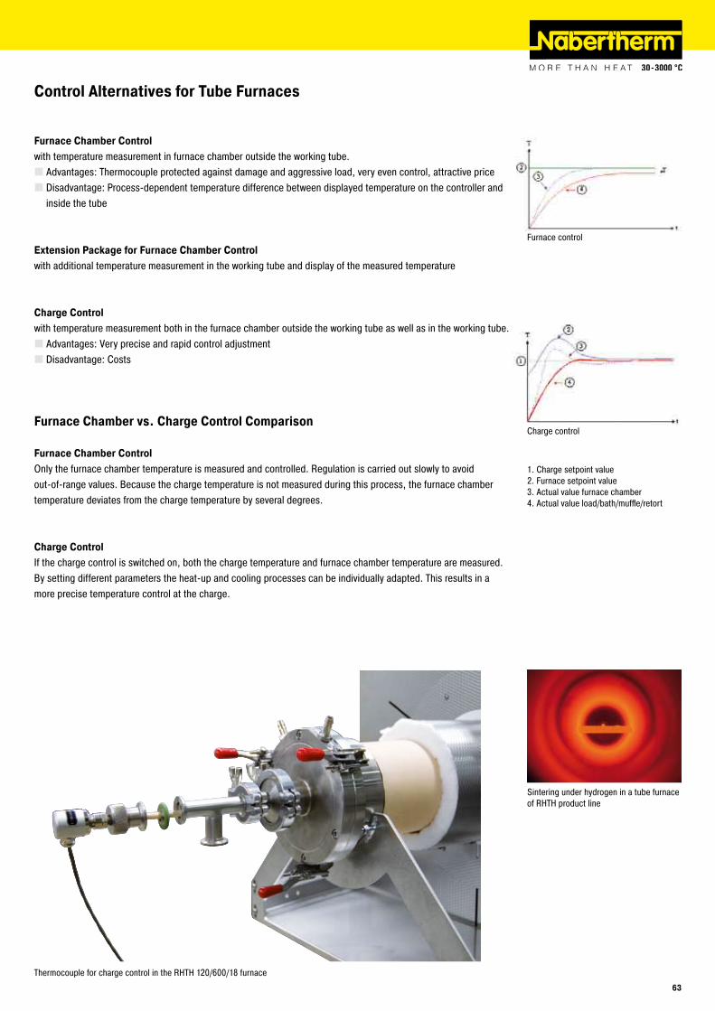
Furnace Chamber Control with temperature measurement in furnace chamber outside the working tube.
Advantages: Thermocouple protected against damage and aggressive load, very even control, attractive priceDisadvantage: Process-dependent temperature difference between displayed temperature on the controller and inside the tube
Extension Package for Furnace Chamber Control with additional temperature measurement in the working tube and display of the measured temperature
Charge Control with temperature measurement both in the furnace chamber outside the working tube as well as in the working tube.
Advantages: Very precise and rapid control adjustmentDisadvantage: Costs
Furnace Chamber vs. Charge Control Comparison
Furnace Chamber ControlOnly the furnace chamber temperature is measured and controlled. Regulation is carried out slowly to avoid out-of-range values. Because the charge temperature is not measured during this process, the furnace chamber temperature deviates from the charge temperature by several degrees.
Charge ControlIf the charge control is switched on, both the charge temperature and furnace chamber temperature are measured. By setting different parameters the heat-up and cooling processes can be individually adapted. This results in a more precise temperature control at the charge.
1. Charge setpoint value2. Furnace setpoint value3. Actual value furnace chamber4. Actual value load/bath/muffle/retort
Furnace control
Charge control
Thermocouple for charge control in the RHTH 120/600/18 furnace
Control Alternatives for Tube Furnaces
Sintering under hydrogen in a tube furnace of RHTH product line
��
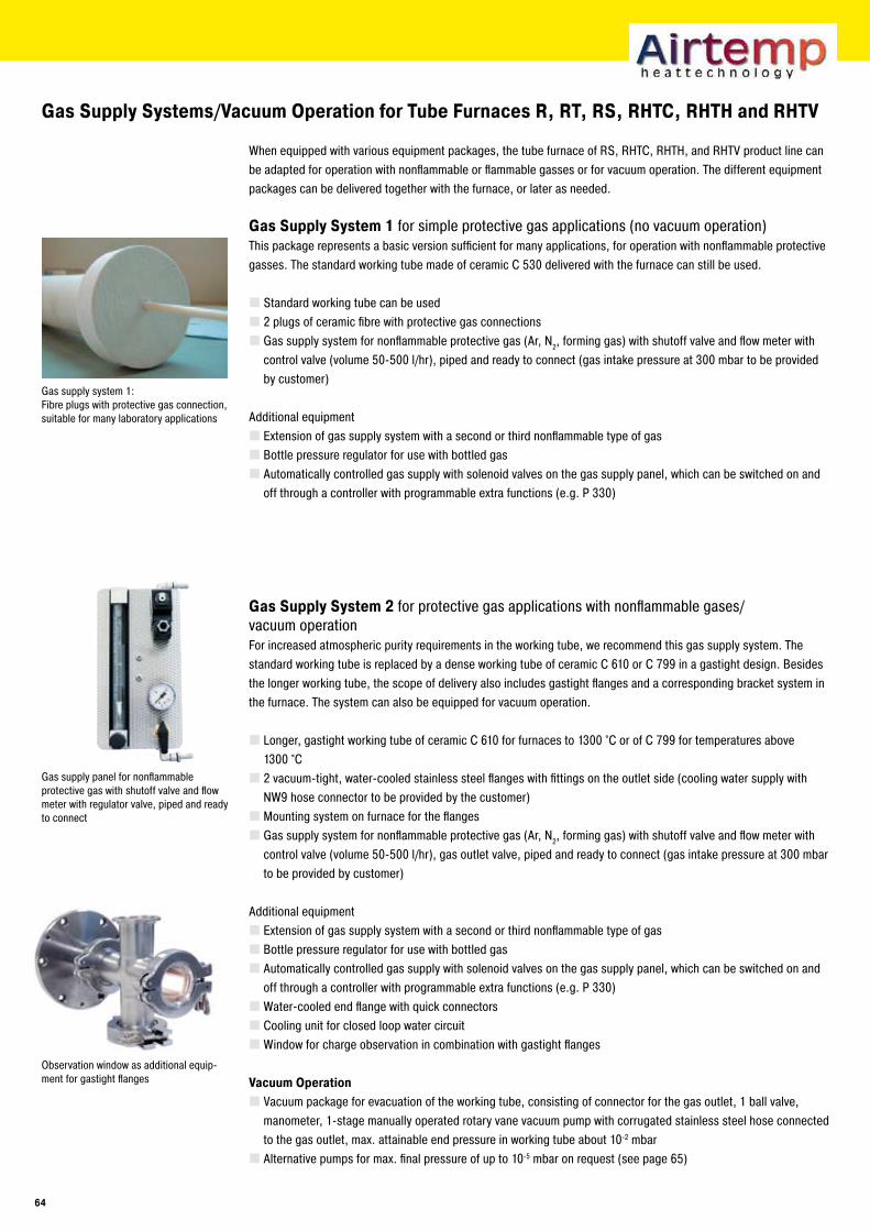
Gas Supply Systems/Vacuum Operation for Tube Furnaces R, RT, RS, RHTC, RHTH and RHTV
When equipped with various equipment packages, the tube furnace of RS, RHTC, RHTH, and RHTV product line can be adapted for operation with nonflammable or flammable gasses or for vacuum operation. The different equipment packages can be delivered together with the furnace, or later as needed.
Gas Supply System 1 for simple protective gas applications (no vacuum operation)This package represents a basic version sufficient for many applications, for operation with nonflammable protective gasses. The standard working tube made of ceramic C 530 delivered with the furnace can still be used.
Standard working tube can be used2 plugs of ceramic fibre with protective gas connectionsGas supply system for nonflammable protective gas (Ar, N2, forming gas) with shutoff valve and flow meter with control valve (volume 50-500 l/hr), piped and ready to connect (gas intake pressure at 300 mbar to be provided by customer)
Additional equipmentExtension of gas supply system with a second or third nonflammable type of gasBottle pressure regulator for use with bottled gasAutomatically controlled gas supply with solenoid valves on the gas supply panel, which can be switched on and off through a controller with programmable extra functions (e.g. P 330)
Gas Supply System � for protective gas applications with nonflammable gases/vacuum operationFor increased atmospheric purity requirements in the working tube, we recommend this gas supply system. The standard working tube is replaced by a dense working tube of ceramic C 610 or C 799 in a gastight design. Besides the longer working tube, the scope of delivery also includes gastight flanges and a corresponding bracket system in the furnace. The system can also be equipped for vacuum operation.
Longer, gastight working tube of ceramic C 610 for furnaces to 1300 °C or of C 799 for temperatures above 1300 °C2 vacuum-tight, water-cooled stainless steel flanges with fittings on the outlet side (cooling water supply with NW9 hose connector to be provided by the customer)Mounting system on furnace for the flangesGas supply system for nonflammable protective gas (Ar, N2, forming gas) with shutoff valve and flow meter with control valve (volume 50-500 l/hr), gas outlet valve, piped and ready to connect (gas intake pressure at 300 mbar to be provided by customer)
Additional equipmentExtension of gas supply system with a second or third nonflammable type of gasBottle pressure regulator for use with bottled gasAutomatically controlled gas supply with solenoid valves on the gas supply panel, which can be switched on and off through a controller with programmable extra functions (e.g. P 330)Water-cooled end flange with quick connectorsCooling unit for closed loop water circuitWindow for charge observation in combination with gastight flanges
Vacuum OperationVacuum package for evacuation of the working tube, consisting of connector for the gas outlet, 1 ball valve, manometer, 1-stage manually operated rotary vane vacuum pump with corrugated stainless steel hose connected to the gas outlet, max. attainable end pressure in working tube about 10-2 mbarAlternative pumps for max. final pressure of up to 10-5 mbar on request (see page 65)
Gas supply panel for nonflammable protective gas with shutoff valve and flow meter with regulator valve, piped and ready to connect
Gas supply system 1: Fibre plugs with protective gas connection, suitable for many laboratory applications
Observation window as additional equip-ment for gastight flanges
�4
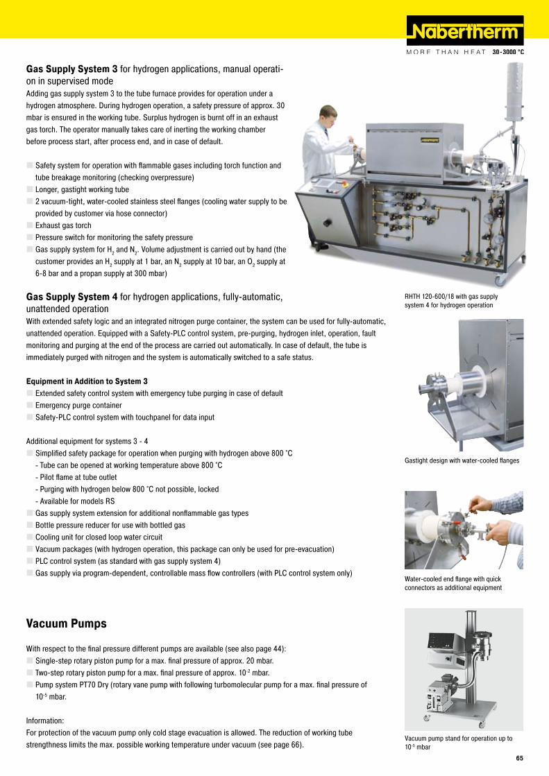
Gastight design with water-cooled flanges
Vacuum pump stand for operation up to 10-5 mbar
RHTH 120-600/18 with gas supply system 4 for hydrogen operation
Vacuum Pumps
With respect to the final pressure different pumps are available (see also page 44):Single-step rotary piston pump for a max. final pressure of approx. 20 mbar.Two-step rotary piston pump for a max. final pressure of approx. 10-2 mbar.Pump system PT70 Dry (rotary vane pump with following turbomolecular pump for a max. final pressure of 10-5 mbar.
Information:For protection of the vacuum pump only cold stage evacuation is allowed. The reduction of working tube strengthness limits the max. possible working temperature under vacuum (see page 66).
Gas Supply System � for hydrogen applications, manual operati-on in supervised modeAdding gas supply system 3 to the tube furnace provides for operation under a hydrogen atmosphere. During hydrogen operation, a safety pressure of approx. 30 mbar is ensured in the working tube. Surplus hydrogen is burnt off in an exhaust gas torch. The operator manually takes care of inerting the working chamber before process start, after process end, and in case of default.
Safety system for operation with flammable gases including torch function and tube breakage monitoring (checking overpressure)Longer, gastight working tube2 vacuum-tight, water-cooled stainless steel flanges (cooling water supply to be provided by customer via hose connector)Exhaust gas torchPressure switch for monitoring the safety pressureGas supply system for H2 and N2. Volume adjustment is carried out by hand (the customer provides an H2 supply at 1 bar, an N2 supply at 10 bar, an O2 supply at 6-8 bar and a propan supply at 300 mbar)
Gas Supply System 4 for hydrogen applications, fully-automatic, unattended operationWith extended safety logic and an integrated nitrogen purge container, the system can be used for fully-automatic, unattended operation. Equipped with a Safety-PLC control system, pre-purging, hydrogen inlet, operation, fault monitoring and purging at the end of the process are carried out automatically. In case of default, the tube is immediately purged with nitrogen and the system is automatically switched to a safe status.
Equipment in Addition to System �Extended safety control system with emergency tube purging in case of defaultEmergency purge containerSafety-PLC control system with touchpanel for data input
Additional equipment for systems 3 - 4Simplified safety package for operation when purging with hydrogen above 800 °C
Tube can be opened at working temperature above 800 °CPilot flame at tube outletPurging with hydrogen below 800 °C not possible, lockedAvailable for models RS
Gas supply system extension for additional nonflammable gas typesBottle pressure reducer for use with bottled gasCooling unit for closed loop water circuitVacuum packages (with hydrogen operation, this package can only be used for pre-evacuation)PLC control system (as standard with gas supply system 4)Gas supply via program-dependent, controllable mass flow controllers (with PLC control system only)
----
Water-cooled end flange with quick connectors as additional equipment
��
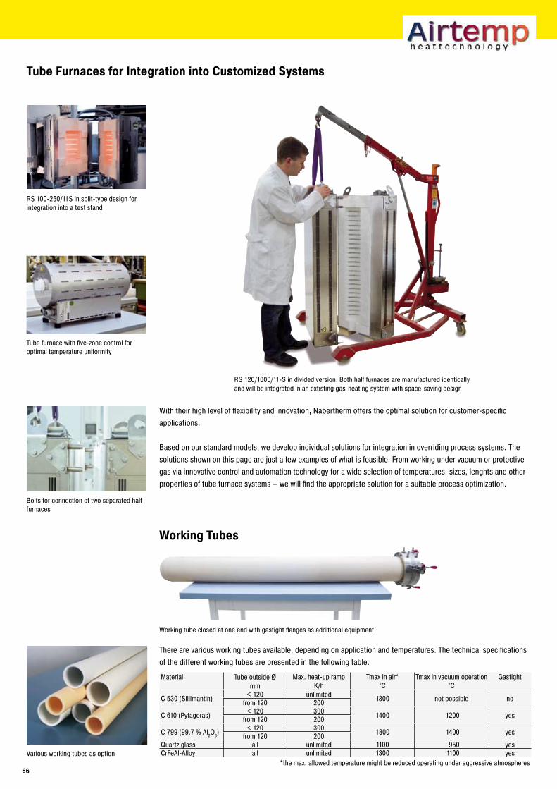
Tube Furnaces for Integration into Customized Systems
With their high level of flexibility and innovation, Nabertherm offers the optimal solution for customer-specific applications.
Based on our standard models, we develop individual solutions for integration in overriding process systems. The solutions shown on this page are just a few examples of what is feasible. From working under vacuum or protective gas via innovative control and automation technology for a wide selection of temperatures, sizes, lenghts and other properties of tube furnace systems – we will find the appropriate solution for a suitable process optimization.
RS 100-250/11S in split-type design for integration into a test stand
Tube furnace with five-zone control for optimal temperature uniformity
Bolts for connection of two separated half furnaces
RS 120/1000/11-S in divided version. Both half furnaces are manufactured identically and will be integrated in an extisting gas-heating system with space-saving design
Various working tubes as option
Working Tubes
Material Tube outside Ømm
Max. heat-up rampK/h
Tmax in air*°C
Tmax in vacuum operation°C
Gastight
C 530 (Sillimantin) < 120 unlimited 1300 not possible nofrom 120 200
C 610 (Pytagoras) < 120 300 1400 1200 yesfrom 120 200
C 799 (99.7 % Al2O3)< 120 300 1800 1400 yesfrom 120 200
Quartz glass all unlimited 1100 950 yesCrFeAl-Alloy all unlimited 1300 1100 yes
*the max. allowed temperature might be reduced operating under aggressive atmospheres
There are various working tubes available, depending on application and temperatures. The technical specifications of the different working tubes are presented in the following table:
Working tube closed at one end with gastight flanges as additional equipment
��
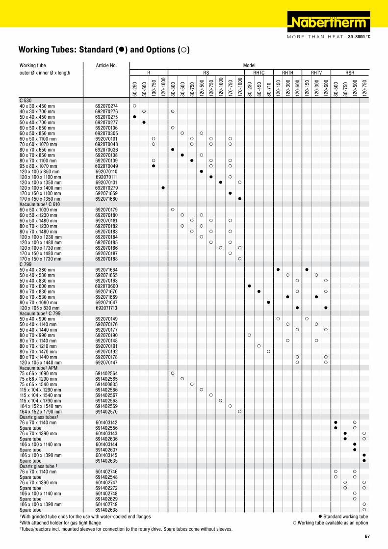
Working Tubes: Standard (l) and Options (¡)
Working tube Article No. Modelouter Ø x inner Ø x length R RS RHTC RHTH RHTV RSR
50-2
50
50-5
00
100-
750
120-
1000
80-3
00
80-5
00
80-7
50
120-
500
120-
750
120-
1000
170-
750
170-
1000
80-2
30
80-4
50
80-7
10
120-
150
120-
300
120-
600
120-
150
120-
300
120-
600
80-5
00
80-7
50
120-
500
120-
750
C 53040 x 30 x 450 mm 692070274 ¡40 x 30 x 700 mm 692070276 ¡ ¡50 x 40 x 450 mm 692070275 l50 x 40 x 700 mm 692070277 l60 x 50 x 650 mm 692070106 ¡60 x 50 x 850 mm 692070305 ¡ ¡60 x 50 x 1100 mm 692070101 ¡ ¡ ¡ ¡70 x 60 x 1070 mm 692070048 ¡ ¡ ¡ ¡80 x 70 x 650 mm 692070036 l80 x 70 x 850 mm 692070108 l ¡80 x 70 x 1100 mm 692070109 ¡ l ¡ ¡95 x 80 x 1070 mm 692070049 l ¡ ¡120 x 100 x 850 mm 692070110 l120 x 100 x 1100 mm 692070111 l ¡120 x 100 x 1350 mm 692070131 l ¡120 x 100 x 1400 mm 692070279 l170 x 150 x 1100 mm 692071659 l170 x 150 x 1350 mm 692071660 lVacuum tube¹ C 61060 x 50 x 1030 mm 692070179 ¡60 x 50 x 1230 mm 692070180 ¡ ¡60 x 50 x 1480 mm 692070181 ¡ ¡ ¡80 x 70 x 1230 mm 692070182 ¡ ¡80 x 70 x 1480 mm 692070183 ¡ ¡ ¡120 x 100 x 1230 mm 692070184 ¡120 x 100 x 1480 mm 692070185 ¡ ¡120 x 100 x 1730 mm 692070186 ¡ ¡170 x 150 x 1480 mm 692070187 ¡170 x 150 x 1730 mm 692070188 ¡C 79950 x 40 x 380 mm 692071664 l l50 x 40 x 530 mm 692071665 ¡ ¡50 x 40 x 830 mm 692070163 ¡ ¡80 x 70 x 600 mm 692070600 l80 x 70 x 830 mm 692071670 l ¡ ¡80 x 70 x 530 mm 692071669 l l80 x 70 x 1080 mm 692071647 l120 x 105 x 830 mm 692071713 l lVacuum tube¹ C 79950 x 40 x 990 mm 692070149 ¡ ¡50 x 40 x 1140 mm 692070176 ¡ ¡50 x 40 x 1440 mm 692070177 ¡ ¡80 x 70 x 990 mm 692070190 ¡80 x 70 x 1140 mm 692070148 ¡ ¡80 x 70 x 1210 mm 692070191 ¡80 x 70 x 1470 mm 692070192 ¡80 x 70 x 1440 mm 692070178 ¡ ¡120 x 105 x 1440 mm 692070147 ¡ ¡Vacuum tube² APM75 x 66 x 1090 mm 691402564 ¡75 x 66 x 1290 mm 691402565 ¡75 x 66 x 1540 mm 691400835 ¡115 x 104 x 1290 mm 691402566 ¡115 x 104 x 1540 mm 691402567 ¡115 x 104 x 1790 mm 691402568 ¡164 x 152 x 1540 mm 691402569 ¡164 x 152 x 1790 mm 691402570 ¡Quartz glass tubes³76 x 70 x 1140 mm 601403142 l ¡Spare tube 691402556 l ¡76 x 70 x 1390 mm 601403143 l ¡Spare tube 691402636 l ¡106 x 100 x 1140 mm 601403144 lSpare tube 691402637 l106 x 100 x 1390 mm 601403145 lSpare tube 691402635 lQuartz glass tube ³76 x 70 x 1140 mm 601402746 ¡ ¡Spare tube 691402548 ¡ ¡76 x 70 x 1390 mm 601402747 ¡ ¡Spare tube 691402272 ¡ ¡106 x 100 x 1140 mm 601402748 ¡Spare tube 691402629 ¡106 x 100 x 1390 mm 601402749 ¡Spare tube 691402638 ¡
¹With grinded tube ends for the use with water-cooled end flanges l Standard working tube²With attached holder for gas tight flange ¡ Working tube available as an option³Tubes/reactors incl. mounted sleeves for connection to the rotary drive. Spare tubes come without sleeves.
��
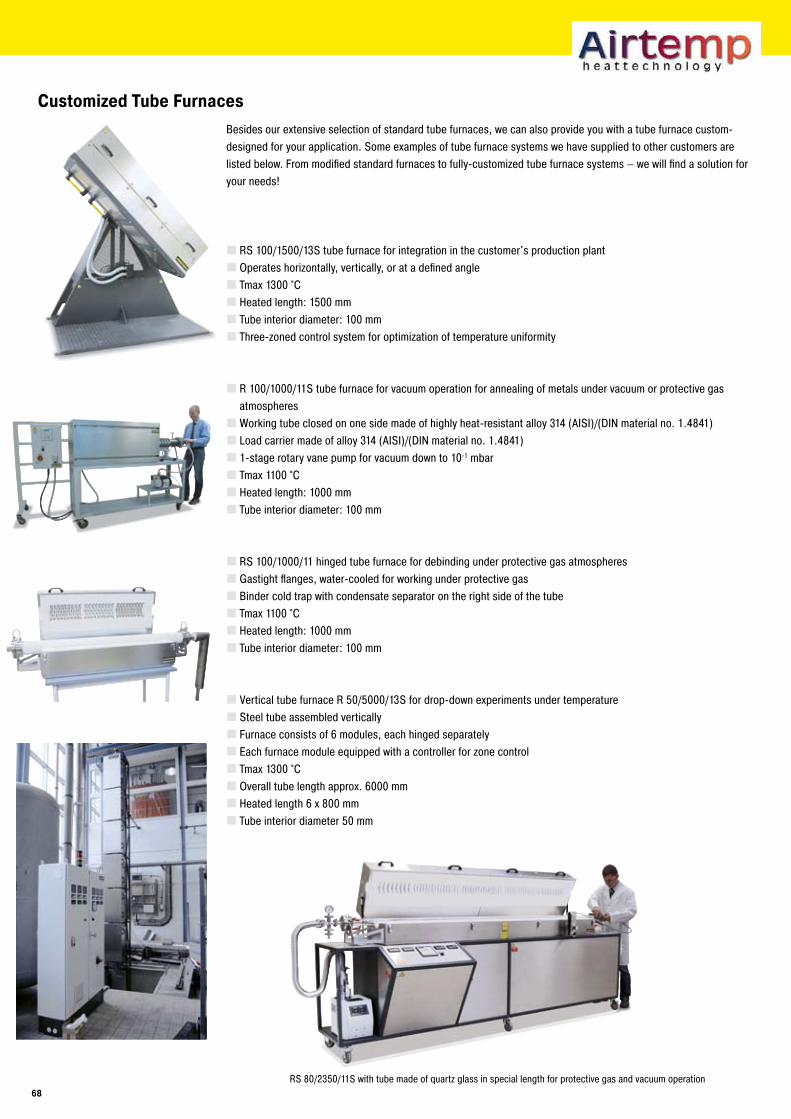
Customized Tube FurnacesBesides our extensive selection of standard tube furnaces, we can also provide you with a tube furnace custom-designed for your application. Some examples of tube furnace systems we have supplied to other customers are listed below. From modified standard furnaces to fully-customized tube furnace systems – we will find a solution for your needs!
RS 100/1500/13S tube furnace for integration in the customer's production plantOperates horizontally, vertically, or at a defined angleTmax 1300 °CHeated length: 1500 mmTube interior diameter: 100 mmThree-zoned control system for optimization of temperature uniformity
R 100/1000/11S tube furnace for vacuum operation for annealing of metals under vacuum or protective gas atmospheresWorking tube closed on one side made of highly heat-resistant alloy 314 (AISI)/(DIN material no. 1.4841)Load carrier made of alloy 314 (AISI)/(DIN material no. 1.4841)1-stage rotary vane pump for vacuum down to 10-1 mbar Tmax 1100 °CHeated length: 1000 mmTube interior diameter: 100 mm
RS 100/1000/11 hinged tube furnace for debinding under protective gas atmospheresGastight flanges, water-cooled for working under protective gasBinder cold trap with condensate separator on the right side of the tubeTmax 1100 °CHeated length: 1000 mmTube interior diameter: 100 mm
Vertical tube furnace R 50/5000/13S for drop-down experiments under temperatureSteel tube assembled verticallyFurnace consists of 6 modules, each hinged separatelyEach furnace module equipped with a controller for zone controlTmax 1300 °COverall tube length approx. 6000 mmHeated length 6 x 800 mmTube interior diameter 50 mm
RS 80/2350/11S with tube made of quartz glass in special length for protective gas and vacuum operation�8
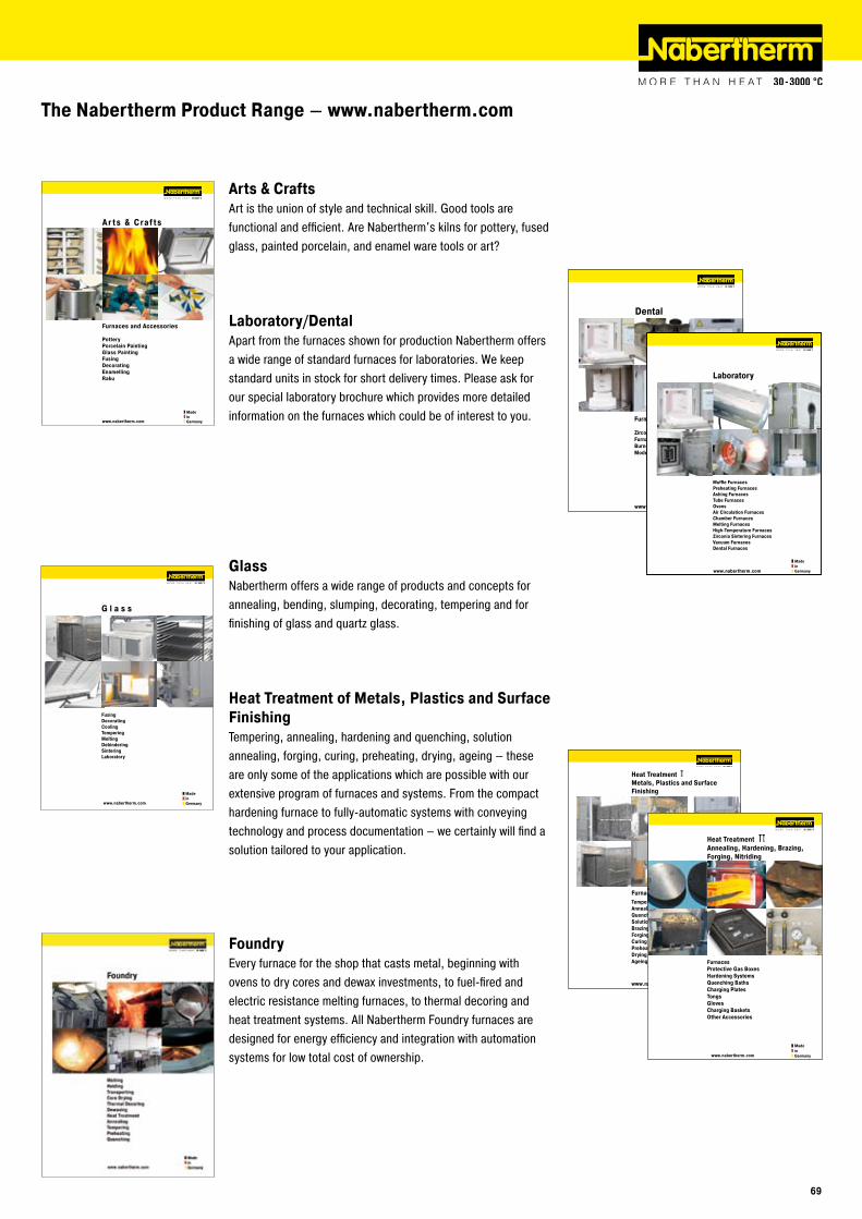
www.nabertherm.com
Madein Germany
Ar ts & Craf ts
Furnaces and Accessories
PotteryPorcelain PaintingGlass PaintingFusingDecoratingEnamellingRaku
www.nabertherm.com
MadeinGermany
FurnacesProtective Gas BoxesHardening SystemsQuenching BathsCharging PlatesTongsGlovesCharging BasketsOther Accessories
Heat TreatmentAnnealing, Hardening, Brazing, Forging, Nitriding
The Nabertherm Product Range – www.nabertherm.com
Arts & CraftsArt is the union of style and technical skill. Good tools are functional and efficient. Are Nabertherm's kilns for pottery, fused glass, painted porcelain, and enamel ware tools or art?
Laboratory/DentalApart from the furnaces shown for production Nabertherm offers a wide range of standard furnaces for laboratories. We keep standard units in stock for short delivery times. Please ask for our special laboratory brochure which provides more detailed information on the furnaces which could be of interest to you.
GlassNabertherm offers a wide range of products and concepts for annealing, bending, slumping, decorating, tempering and for finishing of glass and quartz glass.
Heat Treatment of Metals, Plastics and Surface FinishingTempering, annealing, hardening and quenching, solution annealing, forging, curing, preheating, drying, ageing – these are only some of the applications which are possible with our extensive program of furnaces and systems. From the compact hardening furnace to fully-automatic systems with conveying technology and process documentation – we certainly will find a solution tailored to your application.
FoundryEvery furnace for the shop that casts metal, beginning with ovens to dry cores and dewax investments, to fuel-fired and electric resistance melting furnaces, to thermal decoring and heat treatment systems. All Nabertherm Foundry furnaces are designed for energy efficiency and integration with automation systems for low total cost of ownership.
��
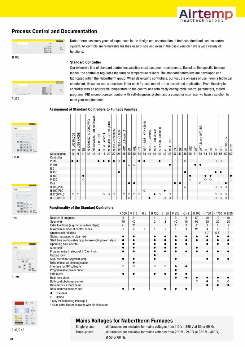
B 180
P 330
P 300
B 150
P 310
C 40/C 42
P startstop
Info
timemin
P 300
wait time 3 time 4time 2time 1
Temp.
T2
T1
Extra1
Extra2 1 2
5
8
0
4
7
3
6
9
P startstop
Info
timemin
P 310
wait time 3 time 4time 2time 1
Temp.
T2
T1
1 / 2
Extra1
Extra2 1 2
5
8
0
4
7
3
6
9
Process Control and Documentation
Nabertherm has many years of experience in the design and construction of both standard and custom control system. All controls are remarkable for their ease of use and even in the basic version have a wide variety of functions.
Standard ControllerOur extensive line of standard controllers satisfies most customer requirements. Based on the specific furnace model, the controller regulates the furnace temperature reliably. The standard controllers are developed and fabricated within the Nabertherm group. When developing controllers, our focus is on ease of use. From a technical standpoint, these devices are custom-fit for each furnace model or the associated application. From the simple controller with an adjustable temperature to the control unit with freely configurable control parameters, stored programs, PID microprocessor control with self-diagnosis system and a computer interface, we have a solution to meet your requirements.
Assignment of Standard Controllers to Furnace Families
Mains Voltages for Nabertherm FurnacesSingle-phase: all furnaces are available for mains voltages from 110 V - 240 V at 50 or 60 Hz.Three-phase: all furnaces are available for mains voltages from 200 V - 240 V or 380 V - 480 V, at 50 or 60 Hz.
Functionality of the Standard Controllers
P 300 P 310 R 6 B 150 B 180 P 330 C 42 H 100 H 700 H 1700 H 3700Number of programs 9 9 1 1 9 9 50 10 10 10Segments 40 40 2 2 40 18 99 20 20 20Extra functions (e.g. fan or autom. flaps) 2¹ 2¹ 2 2 2 2 5 8Maximum number of control zones 1 2 1 1 1 1 1 �² 4 8 8Graphic color display 5,7" 5,7" 12"Status messages in clear text l l l l l l l l l lStart time configurable (e.g. to use night power rates) l l l l l l l l l lOperating hour counter l l l l l l l l lAuto tune l l l l l lProgram entry in steps of 1 °C or 1 min. l l l l l l l l l lKeypad lock lSkip-button for segment jump l l l l l l lDrive of manual zone regulation lInterface for MV software ¡ ¡ ¡ ¡ l lProgrammable power outlet lkWh meter l l l l l lReal-time clock l l l l l lBath control/charge control ¡ l ¡ ¡
Data entry via touchpanel l l lData input via number pad l l l l ll Standard¡ Option¹ only for Debinding Package I ² as an extra feature in ovens with air circulation
N ../
65 H
ACDB
W ..
/60
HACD
B
TR N 10
0/W
AX -
N 20
00/W
AX
NB 6
00/W
AX -
NB 1
000/
WAX
W ..
+ W
.../D
B
H ../
LB o
der L
T
N 20
0/DB
- N
1000
/HDB
N 10
0 - N
220
0/14
NB 3
00 -
NB 6
00
HTC
../LB
ode
r LT
HT HFL
HTB
NRA
12/0
6 - N
RA 4
30/1
1
NRA
.. H 2 v
ersi
on
NRA
.. ID
B ve
rsio
n
SRA
500
- SR
1000
VHT
NRA
..CDB
LS GR
LH HTC
LHT
LHT/
LB u
nd L
HT/L
BR
R RT RS RSR
RHTH
/RHT
V
RHTC
Catalog page 8 9 11 12 12 14 18 20 22 24 26 30 32 34 38 40 40 41 42 46 47 47 48 50 51 52 54 55 56 58 60 62ControllerP 300 l¹ l¹ l l l l ¡ l l l l ¡ ¡ ¡
P 310 ¡ ¡ l l lR 6B 150 l l l lB 180 l l l l lP 330 ¡ ¡ ¡ ¡ ¡
C42 l l l l ¡ lH 100/PLC ¡ ¡ ¡ ¡
H 700/PLC ¡ lH 1700/PLC ¡ ¡ ¡ ¡ ¡ ¡ ¡ ¡ ¡ l ¡ ¡ ¡ ¡ ¡
H 3700/PLC ¡ l ¡ ¡ ¡ ¡ ¡
�0
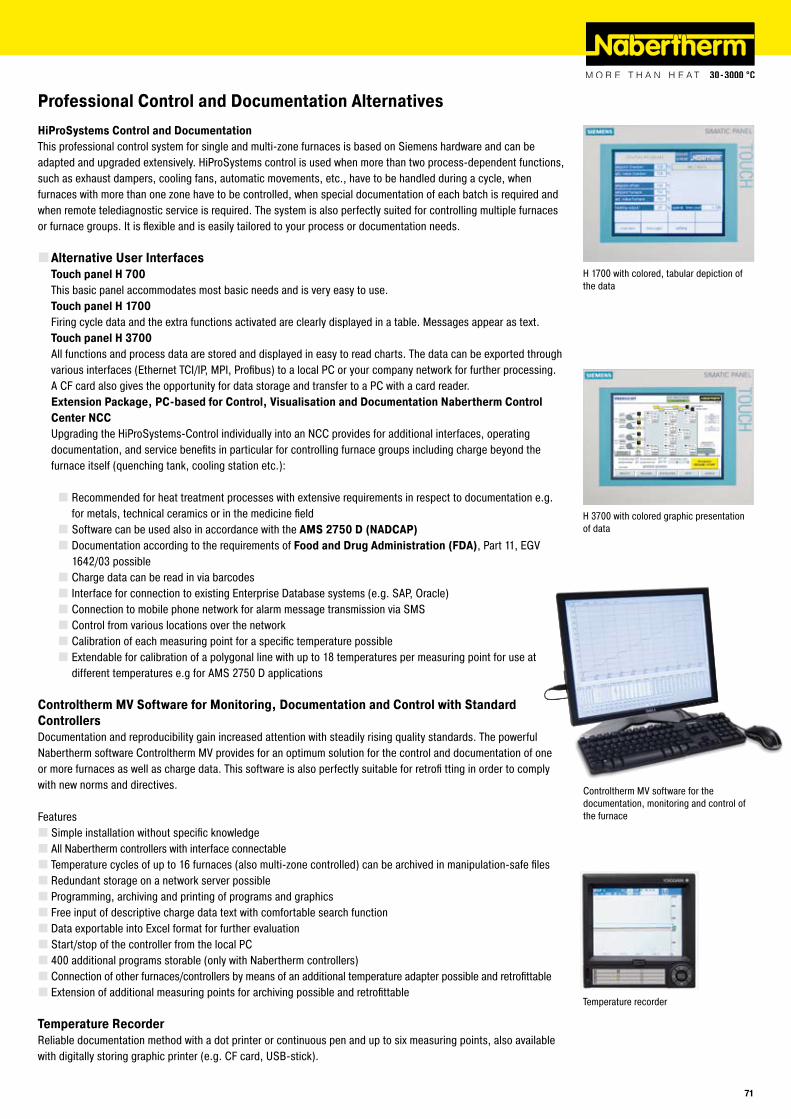
Professional Control and Documentation Alternatives
H 3700 with colored graphic presentation of data
H 1700 with colored, tabular depiction of the data
Temperature recorder
HiProSystems Control and DocumentationThis professional control system for single and multi-zone furnaces is based on Siemens hardware and can be adapted and upgraded extensively. HiProSystems control is used when more than two process-dependent functions, such as exhaust dampers, cooling fans, automatic movements, etc., have to be handled during a cycle, when furnaces with more than one zone have to be controlled, when special documentation of each batch is required and when remote telediagnostic service is required. The system is also perfectly suited for controlling multiple furnaces or furnace groups. It is flexible and is easily tailored to your process or documentation needs.
Alternative User InterfacesTouch panel H �00This basic panel accommodates most basic needs and is very easy to use.Touch panel H 1�00Firing cycle data and the extra functions activated are clearly displayed in a table. Messages appear as text.Touch panel H ��00All functions and process data are stored and displayed in easy to read charts. The data can be exported through various interfaces (Ethernet TCI/IP, MPI, Profibus) to a local PC or your company network for further processing. A CF card also gives the opportunity for data storage and transfer to a PC with a card reader.Extension Package, PC-based for Control, Visualisation and Documentation Nabertherm Control Center NCCUpgrading the HiProSystems-Control individually into an NCC provides for additional interfaces, operating documentation, and service benefits in particular for controlling furnace groups including charge beyond the furnace itself (quenching tank, cooling station etc.):
Recommended for heat treatment processes with extensive requirements in respect to documentation e.g. for metals, technical ceramics or in the medicine fieldSoftware can be used also in accordance with the AMS ���0 D (NADCAP)Documentation according to the requirements of Food and Drug Administration (FDA), Part 11, EGV 1642/03 possibleCharge data can be read in via barcodesInterface for connection to existing Enterprise Database systems (e.g. SAP, Oracle)Connection to mobile phone network for alarm message transmission via SMSControl from various locations over the networkCalibration of each measuring point for a specific temperature possibleExtendable for calibration of a polygonal line with up to 18 temperatures per measuring point for use at different temperatures e.g for AMS 2750 D applications
Controltherm MV Software for Monitoring, Documentation and Control with Standard ControllersDocumentation and reproducibility gain increased attention with steadily rising quality standards. The powerful Nabertherm software Controltherm MV provides for an optimum solution for the control and documentation of one or more furnaces as well as charge data. This software is also perfectly suitable for retrofi tting in order to comply with new norms and directives.
FeaturesSimple installation without specific knowledgeAll Nabertherm controllers with interface connectableTemperature cycles of up to 16 furnaces (also multi-zone controlled) can be archived in manipulation-safe filesRedundant storage on a network server possibleProgramming, archiving and printing of programs and graphicsFree input of descriptive charge data text with comfortable search functionData exportable into Excel format for further evaluationStart/stop of the controller from the local PC400 additional programs storable (only with Nabertherm controllers)Connection of other furnaces/controllers by means of an additional temperature adapter possible and retrofittableExtension of additional measuring points for archiving possible and retrofittable
Temperature RecorderReliable documentation method with a dot printer or continuous pen and up to six measuring points, also available with digitally storing graphic printer (e.g. CF card, USB-stick).
Controltherm MV software for the documentation, monitoring and control of the furnace
�1
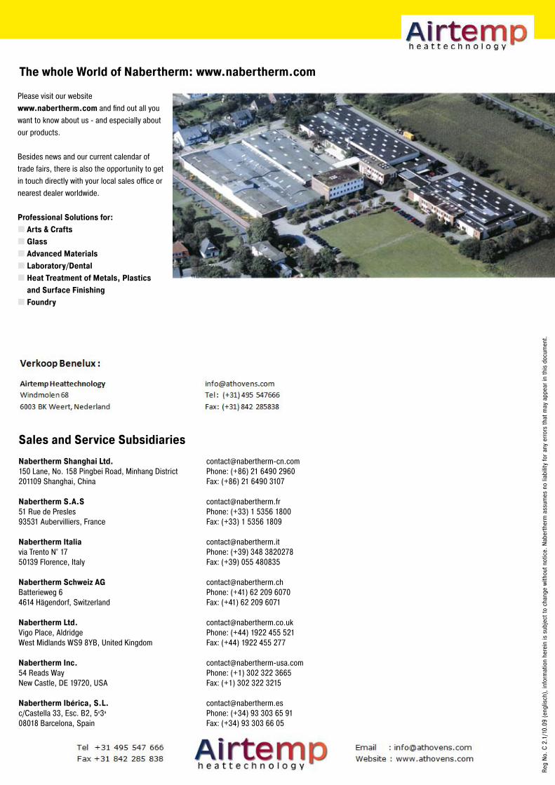
www.nabertherm.com
Please visit our website www.nabertherm.com and find out all you want to know about us - and especially about our products.
Besides news and our current calendar of trade fairs, there is also the opportunity to get in touch directly with your local sales office or nearest dealer worldwide.
Professional Solutions for:Arts & CraftsGlassAdvanced MaterialsLaboratory/DentalHeat Treatment of Metals, Plastics and Surface FinishingFoundry
The whole World of Nabertherm: www.nabertherm.com
Reg
No. C
2.1
/10.
09 (e
nglis
ch),
info
rmat
ion
here
in is
sub
ject
to c
hang
e wi
thou
t not
ice.
Nab
erth
erm
ass
umes
no
liabi
lity
for a
ny e
rrors
that
may
app
ear i
n th
is d
ocum
ent.
[email protected]: (+49) 4298 922-0Fax: (+49) 4298 922-129
[email protected]: (+86) 21 6490 2960Fax: (+86) 21 6490 3107
[email protected]: (+33) 1 5356 1800Fax: (+33) 1 5356 1809
[email protected]: (+39) 348 3820278Fax: (+39) 055 480835
[email protected]: (+41) 62 209 6070Fax: (+41) 62 209 6071
[email protected]: (+44) 1922 455 521Fax: (+44) 1922 455 277
[email protected]: (+1) 302 322 3665Fax: (+1) 302 322 3215
[email protected]: (+34) 93 303 65 91Fax: (+34) 93 303 66 05
Headquarters:
Nabertherm GmbHBahnhofstr. 2028865 Lilienthal, Germany
Sales and Service Subsidiaries
Nabertherm Shanghai Ltd.150 Lane, No. 158 Pingbei Road, Minhang District201109 Shanghai, China
Nabertherm S.A.S51 Rue de Presles93531 Aubervilliers, France
Nabertherm Italiavia Trento N° 1750139 Florence, Italy
Nabertherm Schweiz AG Batterieweg 64614 Hägendorf, Switzerland
Nabertherm Ltd.Vigo Place, AldridgeWest Midlands WS9 8YB, United Kingdom
Nabertherm Inc.54 Reads WayNew Castle, DE 19720, USA
Nabertherm Ibérica, S.L.c/Castella 33, Esc. B2, 5o3a
08018 Barcelona, Spain