N92-22533 - NASA...N92-22533 ROTORCRAFT TRANSMISSIONS John J. Coy SUlVlbIARY The NASA Lewis Research...
12
N92-22533 ROTORCRAFT TRANSMISSIONS John J. Coy SUlVlbIARY The NASA Lewis Research Center and the U.S. Army Aviation Systems Command share an interest in advancing the technology for helicopter propulsion sys- tems. In particular, this paper presents highlights from that portion of the program in drive train technology and the related mechanical components. The major goals of the program are to increase life, reliability, and maintainabil- ity, to reduce weight, noise, and vibration, and to maintain the relatively high mechanical efficiency of the gear train. The current activity emphasizes noise reduction technology and analytical code development followed by experi- mental verification. Selected significant advances in technology for transmis- sions are reviewed, including advanced configurations and new analytical tools. Finally, the plan for transmission research in the future is presented. INTRODUCTION Since 1970 the NASA Lewis Research Center and the U.S. Army Aviation Sys- tems Command have shared an interest in advancing the technology for helicopter propulsion systems. The major goals of the program are to increase life, reli- ability, and maintainability, to reduce weight, noise, and vibration, and to maintain the relatively high mechanical efficiency of the gear train (fig. i, ref. i). Highlights from the current research activity are presented next. ANALYSIS The current activity emphasizes analytical code development and validation with emphasis on noise reduction technology for drive systems (fig. 2). There is a gear technology effort which supports advances in life, higher power den- sity, and lubrication for gears. On the basis of experimental, analytical, and design studies conducted under the transmission technology program, some advanced transmission concepts were evolved, including the advanced 500-hp transmission, the bearingless plan- etary transmission, and the split-torque transmission. An extensive data base has been established for two sizes of helicopter transmissions. The Army's UH-60 Blackhawk transmission has been run in the Lewis test stand to determine thermal, vibration, stress, and efficiency infor- mation for a matrix of operating conditions (ref. 2). This information is 303 https://ntrs.nasa.gov/search.jsp?R=19920013290 2020-04-21T09:02:28+00:00Z
Transcript of N92-22533 - NASA...N92-22533 ROTORCRAFT TRANSMISSIONS John J. Coy SUlVlbIARY The NASA Lewis Research...

N92-22533
ROTORCRAFT TRANSMISSIONS
John J. Coy
SUlVlbIARY
The NASA Lewis Research Center and the U.S. Army Aviation Systems Command
share an interest in advancing the technology for helicopter propulsion sys-
tems. In particular, this paper presents highlights from that portion of the
program in drive train technology and the related mechanical components. The
major goals of the program are to increase life, reliability, and maintainabil-
ity, to reduce weight, noise, and vibration, and to maintain the relatively
high mechanical efficiency of the gear train. The current activity emphasizes
noise reduction technology and analytical code development followed by experi-
mental verification. Selected significant advances in technology for transmis-
sions are reviewed, including advanced configurations and new analytical tools.
Finally, the plan for transmission research in the future is presented.
INTRODUCTION
Since 1970 the NASA Lewis Research Center and the U.S. Army Aviation Sys-
tems Command have shared an interest in advancing the technology for helicopter
propulsion systems. The major goals of the program are to increase life, reli-
ability, and maintainability, to reduce weight, noise, and vibration, and to
maintain the relatively high mechanical efficiency of the gear train (fig. i,
ref. i). Highlights from the current research activity are presented next.
ANALYSIS
The current activity emphasizes analytical code development and validation
with emphasis on noise reduction technology for drive systems (fig. 2). There
is a gear technology effort which supports advances in life, higher power den-
sity, and lubrication for gears.
On the basis of experimental, analytical, and design studies conducted
under the transmission technology program, some advanced transmission concepts
were evolved, including the advanced 500-hp transmission, the bearingless plan-
etary transmission, and the split-torque transmission.
An extensive data base has been established for two sizes of helicopter
transmissions. The Army's UH-60 Blackhawk transmission has been run in the
Lewis test stand to determine thermal, vibration, stress, and efficiency infor-
mation for a matrix of operating conditions (ref. 2). This information is
303
https://ntrs.nasa.gov/search.jsp?R=19920013290 2020-04-21T09:02:28+00:00Z
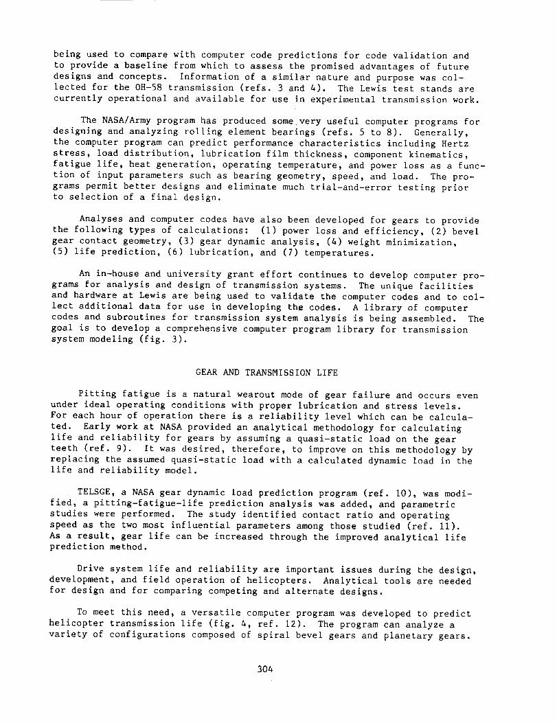
being used to compare with computer code predictions for code validation and
to provide a baseline from which to assess the promised advantages of future
designs and concepts. Information of a similar nature and purpose was col-
lected for the 0H-58 transmission (refs. 3 and 4). The Lewis test stands are
currently operational and available for use in experimental transmission work.
The NASA/Army program has produced somevery useful computer programs for
designing and analyzing rolling element bearings (refs. 5 to 8). Generally,
the computer program can predict performance characteristics including Hertz
stress, load distribution, lubrication film thickness, component kinematics,
fatigue life, heat generation, operating temperature, and power loss as a func-
tion of input parameters such as bearing geometry, speed, and load. The pro-
grams permit better designs and eliminate much trial-and-error testing prior
to selection of a final design.
Analyses and computer codes have also been developed for gears to provide
the following types of calculations: (1) power loss and efficiency, (2) bevel
gear contact geometry, (3) gear dynamic analysis, (4) weight minimization,
(5) life prediction, (6) lubrication, and (7) temperatures.
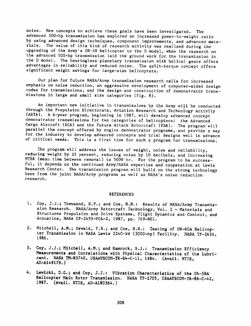
An in-house and university grant effort continues to develop computer pro-
grams for analysis and design of transmission systems. The unique facilities
and hardware at Lewis are being used to validate the computer codes and to col-
lect additional data for use in developing the codes. A library of computer
codes and subroutines for transmission system analysis is being assembled. The
goal is to develop a comprehensive computer program library for transmission
system modeling (fig. 3).
GEAR AND TRANSMISSION LIFE
Pitting fatigue is a natural wearout mode of gear failure and occurs even
under ideal operating conditions with proper lubrication and stress levels.
For each hour of operation there is a reliability level which can be calcula-
ted. Early work at NASA provided an analytical methodology for calculating
life and reliability for gears by assuming a quasi-static load on the gear
teeth (ref. 9). It was desired, therefore, to improve on this methodology by
replacing the assumed quasi-static load with a calculated dynamic load in the
life and reliability model.
TELSGE, a NASA gear dynamic load prediction program (ref. i0), was modi-
fied, a pitting-fatigue-life prediction analysis was added, and parametric
studies were performed. The study identified contact ratio and operating
speed as the two most influential parameters among those studied (ref. ii).
As a result, gear life can be increased through the improved analytical lifeprediction method.
Drive system life and reliability are important issues during the design,
development, and field operation of helicopters. Analytical tools are needed
for design and for comparing competing and alternate designs.
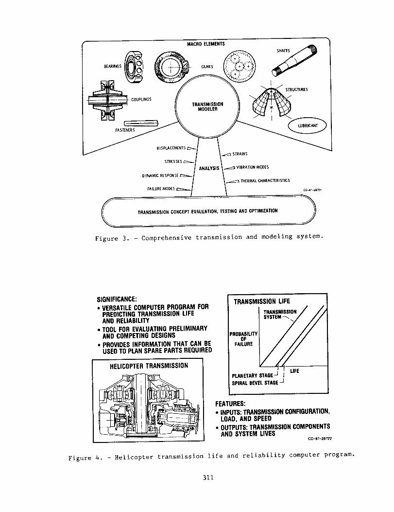
To meet this need, a versatile computer program was developed to predict
helicopter transmission life (fig. 4, ref. 12). The program can analyze a
variety of configurations composed of spiral bevel gears and planetary gears.
304

The program determines the forces on each bearing and gear for a given trans-mission configuration and applied load. The life of each bearing and gear is
determined. Program output includes component and total system lives and load
capacity for a given mission profile. The program predicts mean time between
failures (MTBF) and can be used to evaluate proposed new designs and to project
spare parts requirements for helicopter fleet operations.
GEAR NOISE
Historically, helicopters have been plagued by internal noise problems.
Noise levels range from I00 to 120 dBa in the cabin. The sound can be from
many sources, such as the transmission gear noise, the turbine engine compres-
sor and exhaust noise, the rotor blades, and air turbulence. The transmission
is a particularly troublesome source and is believed to be the main source of
annoying noise in the helicopter cabin. The noise from the transmission enters
the cabin following two paths: structure-borne radiation and direct radiation
(fig. 5). The magnitude of the direct radiation is a function of the acoustic
power radiated from the transmission case, transmitted acoustically to the
cabin outer walls, and transferred through to the cabin. Of course if there
are any small openings in the wall between the transmission compartment and the
cabin, the sound will directly enter the cabin. The structure-borne path is
particularly hard to block because the transmission case and its mounts are an
integral part of the lift-load bearing path. The transmission mounts must be
strong enough to support the entire helicopter by transferring the lift-load
from the rotor blades to the air frame, and rigid enough for stable control of
the helicopter. The stiff mounts pass the gear vibrations exceedingly well to
the airframe, and the sound transmits to the cabin directly.
The major portion of our program in transmissions is devoted to finding
solutions to this problem.
Spiral bevel gears are used in helicopters to transmit power "around the
corner" from a horizontal engine output shaft to the vertical rotor shaft.
Vibration from spiral bevel gears is a strong source of transmission noise
(fig. 6, ref. 13).
The goal of a recent study was to relate gear noise to physical factors
such as deviations of tooth surfaces and gear shaft centerlines from their
ideal positions, tooth and gear body stiffness, bearing and housing support
flexibility, and input shaft torque. Equations have been developed for comput-
ing the vibration and noise of the gear drive system. The work completed
(i) provides the first detailed mathematical understanding of generalized
transmission error in spiral bevel gears, (2) allows prediction of vibration
excitation based on gear tooth measurements, and (3) relates gear noise to
physical design parameters and therefore provides a basis for future improve-
ments in spiral bevel gear design (ref. 14).
ADVANCED TRANSMISSIONS
Advancements in transmissions can come from either improved components or
improved designs of the transmission system (fig. 7). The split-torque
arrangement is in the second category. The figure shows a split-torque design
which is compatible with the Blackhawk (UH-60A) helicopter. The fundamental
305

concept of the split-torque design is that the power from the engine is dividedinto two parallel paths prior to recombination on a single gear that drives theoutput shaft. Studies have shownthat replacement of the planetary gear reduc-tion stage with a split torque results in weight savings and increased relia-bility (ref. 15). There can be manypinions driving the output gear, but inthe case of the UH-60Aapplication it was found that four pinions gave theoptimumdesign on the basis of least overall weight, reduced power losses, com-parable total parts count comparedto the existing UH-60design, and leastnumber (one) of nonredundant gears. The advantage of split torque over plan-etary is greatest for the larger sized helicopters.
The engineering analysis showedthat the following performance benefitscan be achieved for a 3600-hp split-torque transmission comparedwith the con-ventional transmission with a planetary gear stage: (i) weight is reduced15 percent, (2) drive train power losses are reduced by 9 percent, (3) relia-bility is improved and vulnerability is reduced because of redundant powerpaths, and (4) the numberof noise generation points (gear meshes) is reduced.
The transmission has potential for installation in the Blackhawk helicop-ter. The design study has carried the transmission to the detail design stagefor a test model to be used for validation studies in the NASALewis 3000-hphelicopter transmission facility, but a test model has not been built. For thetransmission to be used in the Blackhawk, a separate detail design and instal-lation study would be required first.
The design emphasis for the NASA/Bell Helicopter Textron (BHT) 500-hpadvanced technology demonstrator transmission was placed on a 500-hp version ofthe 0fl-58C, 317-hp transmission that would have a long, quiet life with a mini-mumincrease in the cost, weight, and space that usually increases along withpower increases. This was accomplished by implementing advanced technologythat has been developed during the last decadeand making improvements dictatedby field experience (ref. 16).
These advanced technology components, concepts, and improvements, andtheir effect on the 500-hp transmission are as follows:
(i) High contact ratio planetary gear teeth reduce the noise level andincrease life.
(2) Improved spiral bevel gears madeof vacuumcarburized gear steels,shot peened for increased gear tooth pitting fatigue life, as well as geartooth bending fatigue strength, and lubricated with Aeroshell 555 oil saveweight and space and increase transmission life.
(3) Improved bearings, madeof cleaner steels and designed with improvedanalytical tools, save weight and space and increase reliability.
(4) Improved design of the planet carrier, madeof two-piece constructionwith straddle mounting of the planet gears, improves gear alignment and powercapacity.
(5) The cantilever-mounted planetary ring gear has no working spline togenerate wear debris; it isolates the meshing teeth from the housing to reduce
306

noise, and it provides a flexible mount for a more uniform load distribution
among the planets.
(6) The sun gear now has an improved spline (crown hobbed and hardened)
running submerged in a bath of flowthrough oil, which prevents the spline from
wearing.
(7) The straddle-mounted bevel gear allows higher torque to be transmitted
without detrimental shifting of the tooth contact pattern.
In summary, the improved 500-hp design has a weight/horsepower ratio of
0.26 ib/hp, compared to 0.37 ib/hp for the 317-hp 0H-58C transmission. This
transmission is the basis for the transmission in the Army's improved OH-58D
model helicopter.
One recent development in the area of high-performance power transmis-
sions is the self-aligning, bearingless planetary (SABP) (ref. 17). This
transmission arrangement can be generically classified as a quasl-compound
planetary which uses a sun gear, planet spindle assemblies, ring gears, and
rolling rings.
The design study projects a weight savings of 17 to 30 percent and a reli-
ability improvement factor of 2:1 over the standard transmission. The benefits
of using an SABP transmission are most effective when one uses reduction ratios
between 16:1 and 26:1. It permits high reduction in two compound stages of
high efficiency, providing sufficient flexibility and self-centering to give
good load distribution between planet pinions, while effectively isolating the
planetary elements from housing deflections.
This new transmission concept offers advantages over transmissions that
use conventional planetary gears: higher reduction ratio, lighter weight,
increased reliability, and decreased vulnerability. Since it has no planet
bearings, there is a weight savings, and power losses and bearing failures com-
monly associated with conventional-design transmissions are nonexistent.
In conventional-design transmissions, planet bearings are heavily loaded
and are the weak link when the lubricant is interrupted. The SABP transmission
has decreased vulnerability because of increased operating time after loss of
lubricant since there are no planet bearings.
One SABP transmission with a 17.44:1 ratio is currently being tested in
the 500-hp transmission facility at NASA Lewis, and another variant with a
ratio of i01:i is being fabricated for testing.
FUTURE PLANS
Rotorcraft for the 1990's and beyond require extremely light, long-lived,
quiet drive systems. The NASA/Army research, together with the helicopter
builders' careful designs, has provided reliable and strong drive systems for
civilian and Army helicopters. This paper has reviewed significant research in
drive systems and their components.
The critical issues are (i) to achieve significant advances in power-to-
weight ratio, (2) to increase reliability, and (3) to reduce the transmission
307
noise. New concepts to achieve these goals have been investigated. The
advanced 500-hp transmission has explored an increased power-to-weight ratio
by using advanced design techniques, component improvements, and advanced mate-
rials. The value of this kind of research activity was realized during the
upgrading of the Army's 0H-58 helicopter to the D model, when the research on
the advanced 500-hp transmission laid the ground work for the transmission in
the D model. The bearingless planetary transmission with helical gears offers
advantages in reliability and reduced noise. The split-torque concept offers
significant weight savings for large-size helicopters.
Our plan for future NASA/Army transmission research calls for increased
emphasis on noise reduction, an aggressive development of computer-aided designcodes for transmissions, and the design and construction of demonstrator trans-
missions in large and small size categories (fig. 8).
An important new initiative in transmissions by the Army will be conducted
through the Propulsion Directorate, Aviation Research and Technology Activity
(ARTA). A 6-year program, beginning in 1987, will develop advanced concept
demonstrator transmissions for two categories of helicopters: the Advanced
Cargo Aircraft (ACA) and the Future Attack Rotorcraft (FAR). The program will
parallel the concept offered by engine demonstrator programs, and provide a way
for the industry to develop advanced concepts and trial designs well in advance
of critical needs. This is a first time for such a program for transmissions.
The program will address the issues of weight, noise and reliability,
reducing weight by 25 percent, reducing noise by I0 decibels, and increasing
MTBR (mean time between removal) to 5000 hr. For the program to be success-
ful, it depends on the continued Army/NASA expertise and cooperation at Lewis
Research Center. The transmission program will build on the strong technologybase from the joint NASA/Army programs as well as NASA's noise reductionresearch.
l.
.
.
REFERENCES
Coy, J.J.; Townsend, D.P.; and Coe, H.H.: Results of NASA/Army Transmis-
sion Research. NASA/Army Rotorcraft Technology, Vol. 2 - Materials and
Structures Propulsion and Drive Systems, Flight Dynamics and Control, and
Acoustics, NASA CP-2495-VOL-2, 1987, pp. 769-801.
Mitchell, A.M.; Oswald, F.B.; and Coe, H.H.: Testing of UH-60A Helicop-
ter Transmission in NASA Lewis 2240-kW (3000-hp) Facility. NASA TP-2626,1986.
Coy, J.J.; Mitchell, A.M.; and Hamrock, B.J.: Transmission Efficiency
Measurements and Correlations with Physical Characteristics of the Lubri-
cant. NASA TM-83740, USAAVSCOM-TR-84-C-II, 1984. (Avail. NTIS,AD-AI49179.)
Lewlckl, D.G.; and Coy, J.J.: Vibration Characteristics of the Oh-58A
Helicopter Main Rotor Transmission. NASA TP-2705, USAAVSCOM-TR-86-C-A2,1987. (Avail. NTIS, AD-AI8036A.)
308

.
.
.
Q
.
10.
ii.
12.
13.
14.
15.
16.
17.
Hadden, G.B., et al.: User's Manual for Computer Program AT81Y003
SHABERTH. (SKF-AT81D040, SKF Technology Services; NASA Contract
NAS3-22690) NASA CR-165365, 1981.
Dyba, G.J.; and Kleckner, R.J.: High Speed Cylindrical Roller Bearing
Analysis, SKF Computer Program CYBEAN, Vol. 2 - User's Manual.
(SKF-81ATD049-VOL-2, SKD Technology Services; NASA Contract NAS3-22690)
NASA CR-165364, 1981.
Kleckner, R.J.; Dyba, G.J.; and Ragen, M.A.: SKF Computer Program
SPHERBEAN, Vol II - User's Manual. (AT81DO07, SKF Technology Services;
NASA Contract NAS3-22807) NASA CR-167859, 1982.
Hadden, G.B., et al.: User's Manual for SKF Computer Program AT81YO05,
PLANETSYS. (SKF-AT81D044, SKF Technology Services; NASA Contract
NAS3-22690) NASA CR-165366, 1981.
Coy., J.J.; Townsend, D.P.; and Zaretsky, E.V.: Analysis of Dynamic
Capacity of Low-Contact-Ratio Spur Gears using Lundberg-Palmgren Theory,
NASA TN D-8029, 1975.
Wang, K.L.; and Cheng, H.S.: Thermal Elastohydrodynamic Lubrication of
Spur Gears. NASA CR-3241, 1980.
Lewicki, D.G.: Predicted Effect of Dynamic Load on Pitting Fatigue Life
for Low-Contact-Ratio Spur Gears, NASA TP-2610, AVSCOM-TR-86-C-21, 1986.
(Avail. NTIS, AD-AI70906.)
Savage, M.; and Brikmanis, C.K.: System Life and Reliability Modeling
for Helicopter Transmissions. NASA CR-3967, 1986.
Coy, J.J., et al.: Identification and Proposed Control of Helicopter
Transmission Noise at the Source. NASA/Army Rotorcraft Technology Confer-
ence, Vol. 2 - Materials and Structures, Propulsion and Drive Stysems,
Flight Dynamics and Control, and Acoustics, NASA CP-2495-VOL-2, 1987,
pp. 1045-1065.
Mark, W.D.: Analysis of the Vibratory Excitation Arising from Spiral
Bevel Gears. NASA CR-4081, 1987.
White, G.: 3600-hp Split Torque Helicopter Transmission. NASA
CR-174932, 1985.
Braddock, C.E.; and Battles, R.A.: Design of an Advanced 500 HP Helicop-
ter Transmission. Advanced Power Transmission Technology, G.K. Fischer,
ed., NASA CP-2210, AVRADCOM-TR-82-C-16, 1983, pp. 123-139.
Folenta, D.J.: Design Study of Self-Aligning Bearingless Planetary
(SABP). (TTC-80-01R, Transmission Technology Co. Inc.; NASA Contract
NAS3-21604) NASA CR-159808, 1980.
309

REQUIREMENT
LIGHTER
STRONGER
MORE RELIABLE
QUIETER
GOAL
DRIVE TRAIN SPECIFICWEIGHT0.3 TO 0.5 Iblhp(CURRENTLY0.4 TO 0.6 Iblhp)
5000-hr MEAN TIME BETWEENOVERHAULS(MTBO)(CURRENTLY500 TO 2000 hm)
70 TO 80 dB IN CABIN(CURRENTLY100 TO 110 dB)
BENEFIT
INCREASEDRANGEANDPAYLOAD
LOWEROPERATINGCOSTAND SAFEROPERATION
GREATERUSE FORCOMMER-CIALCOMMUTERSERVICE
INCREASEDPASSENGERANDPILOTCOMFORT
C0-67-28719
Figure i. - Transmission technology required for 1990's.
ANALYTICALCODESAND OPTIMIZATION
ADVANCEDCONFIGURATIONS
VALIDATIONEXPERIMENTS
NOISE REDUCTIONTECHNOLOGY
CD--87-28720
Figure 2. - Current research activity in transmissions.
310
LINGS
rFASTENERS
MACRO ELEMENTS
GEARS
TRANSMISSIONMODELER
DISPLACEMENTS£::_..
STRESSES r"--..._
DYNAMIC RESPONSE
FAILURE MODESC0-§7-2B_I
TRANSMISSION CONCEPT EVALUATION, TESTING AND OPTIMIZATION
Figure 3. - Comprehensive transmission and modeling system.
SIGNIFICANCE:• VERSATILECOMPUTERPROGRAMFOR
PREDICTINGTRANSMISSIONLIFEAND RELIABILITY
• TOOLFOR EVALUATINGPRELIMINARYAND COMPETINGDESIGNS
• PROVIDESINFORMATIONTHAT CAN BEUSEDTO PLANSPAREPARTSREQUIRED
HELICOPTERTRANSMISSION
TRANSMISSIONLIFE
TRANSMISSION/ ,_/
SYSTEM--///
"OB F '"TY/ //
FEATURES:
• INPUTS:TRANSMISSIONCONFIGURATION,LOAD,AND SPEED
• OUTPUTS:TRANSMISSIONCOMPONENTSAND SYSTEM LIVES
CD-87-28722
Figure 4. - Helicopter transmission life and reliability computer program.
311

TRANSMISSION NOISE PATHS
TRANSMISSION--. _. _/
STRUCTURALPATH_. \ _._____
RADIATING-.
II II II II
N
DIRECTRADIATION
• AIRBORNE• ACOUSTIC-INDUCED
STRUCTURE-BORNE
C0-87-28723
Figure 5. - Transmission noise reduction technology for rotorcraft.
VIBRATION
FREQUENCY
MILESTONESCOMPLETED:
• MATHEMATICALMODELOF ZONEOFTOOTHCONTACTFORSPIRALBEVELGEARS
• NEW UNDERSTANDINGOF THREE-DIMENSIONALNATUREOF TOOTHMESHING
• TIME AND FREQUENCYDOMAINANALYSISFORNOISEEXCITATIONFUNCTION
• NASACR 4081
SPIRALBEVELGEARS
SIGNIFICANCE:
• ALLOWSPREDICTIONOFVIBRATIONFROM GEARMEASUREMENTS
• PROVIDESBASISFORFUTUREIMPROVEMENTSIN SPIRALBEVELGEARDESIGN
Figure 6. - Spiral bevel gear noise modeling.
CD-87-28724
312

500-hp BEARINGLESSPLANETARY(LOW-RATIO)
500-hp BEARINGLESSPLANETARY(HIGH-RATIO)
500-hp/ADVANCEDCOMPONENTS
/--ROTOR
/ OUTPUT -TORQUE DIVIOER
/v_TAIL _ENGINE
DRIVE INPUT
3600-hp SPLIT TORQUECD-87-28725
Figure 7. -Advanced transmissions.
ANALYSISAND _ _ LIGHTWEIGHT
VALIDATION "_!__ I _ LOW NOISE
[ ' ._' DESIGN_ [-"' . / LONG LIFEOPTIMIZATION
NEW GEAR GEOMETRY
TEC..OLOGYb NO,SE,SOLATORSkI
21StADVANcEDCENTURY_-,_" _ i
TRANSMISSIONSFOR
U.S. ARMY ADVANCEDROTORCRAFT " _%_CARGOAIRCRAFT (ACA) ,_j_,d_AND FUTURE ATTACK __'_ _-PJ
J TRANSMISSION DEMONSTRATORPROGRj_
cD-eT-2_2e e" ROTORCRAFT(FAR) _ _
Figure 8. - Future thrust.
313