N9032B PXA X-Series Signal Analyzer, Multi-touch
35
Find us at www.keysight.com Page 1 N9032B PXA X-Series Signal Analyzer, Multi-touch 2 Hz to 8.4, 13.6, or 26.5 GHz
Transcript of N9032B PXA X-Series Signal Analyzer, Multi-touch

Find us at www.keysight.com Page 1
N9032B PXA X-Series Signal Analyzer, Multi-touch 2 Hz to 8.4, 13.6, or 26.5 GHz

Find us at www.keysight.com Page 2
Table of Contents
Definition and Terms ..................................................................................................................................... 3 Frequency and Time Specifications .............................................................................................................. 5 Triggers and Gating ...................................................................................................................................... 6 Swept Spectrum Analysis ............................................................................................................................. 7 Amplitude Accuracy ...................................................................................................................................... 8
Amplitude Range ......................................................................................................................................... 11 DANL (Displayed Average Noise Level) ..................................................................................................... 12
Third-Order Intercept (TOI) ......................................................................................................................... 14
Second-Harmonic Intercept (SHI) ............................................................................................................... 16
Gain Compression ...................................................................................................................................... 17 Residuals, Images, and Spurious Responses ............................................................................................ 17
Phase Noise (SSB) ..................................................................................................................................... 18
Wide-Bandwidth IQ Analysis (Demod) ........................................................................................................ 19 5GNR EVM Residuals (“Floor”) vs Power (“Bathtub Curves”) .................................................................... 20
10 MHz Analysis Bandwidth........................................................................................................................ 21
25 MHz Analysis Bandwidth (licensed as Option B25) ............................................................................... 21 40 MHz Analysis Bandwidth (licensed as Option B40) ............................................................................... 22
255 MHz Analysis Bandwidth (licensed as Option B2X) ............................................................................ 23
1 GHz Analysis Bandwidth (Option R10) .................................................................................................... 23 1.5 GHz Analysis Bandwidth (Option R15) ................................................................................................. 25 2 GHz Analysis Bandwidth (Opt R20) ......................................................................................................... 26 Inputs and Outputs ...................................................................................................................................... 27 General Specifications ................................................................................................................................ 31 Regulatory Information ................................................................................................................................ 32 Additional Resources .................................................................................................................................. 35

Find us at www.keysight.com Page 3
Definition and Terms
Specifications describe the performance of parameters covered by the product warranty and apply to temperature ranges 0 to 55 °C, unless otherwise noted.
95th percentile values indicate the breadth of the population (approx. 2 σ) of performance tolerances expected to be met in 95 percent of the cases with a 95 percent confidence, for any ambient temperature in the range of 20 to 30 °C. In addition to the statistical observations of a sample of instruments, these values include the effects of the uncertainties of external calibration references. These values are not warranted. These values are updated occasionally if a significant change in the statistically observed behavior of production instruments is observed.
Typical values (typ) describe additional product performance information that is not covered by the product warranty. It is performance beyond specifications that 80 percent of the units exhibit with a 95 percent confidence level over the temperature range 20 to 30 °C. Typical performance does not include measurement uncertainty.
Nominal values (nom) indicate expected performance or describe product performance that is useful in the application of the product but are not covered by the product warranty.
The analyzer will meet its specifications when:
• It is within its calibration cycle.
• Under auto couple control, except that Auto Sweep Time Rules = Accy
• For signal frequencies < 10 MHz, DC coupling applied.
• Analyzer is used in environment that falls within allowed operating range; and has been in that environment at least 2 hours before being turned on.
• Analyzer has been turned on at least 30 minutes with AutoAlign set to Normal; or, if Auto Align is set to Off or Partial, alignments must have been run recently enough to prevent an Alert message. Note that factory default is with the AutoAlign set to Light, which (compared to Normal) allows wider temperature changes before causing Alignments to run automatically. The benefit is that Alignments interrupt less frequently. The user can change AutoAlign to Normal if desired, and this setting will persist after power cycle or PRESET. If the Alert condition is changed from “Time and Temperature” to one of the disabled duration choices, the analyzer may fail to meet specifications without informing the user. In practice, the impact of such choices is primarily on Absolute Amplitude Accuracy. If temperature changes are small, the impact of Light vs Normal is negligible. Also, the user may invoke Align All at any time, to get the best possible accuracy.
• The term “mixer level” is used as a condition for many specifications in this document. This term is a conceptual quantity that is defined as follows: Mixer Level (dBm) = RF Input Power Level (dBm) - (Mechanical Attenuation) (dB) - (Electronic Attenuation) (dB).
• The term “attenuation” is used for many specifications in this document; this refers to the Mechanical Attenuator, unless otherwise stated.

Find us at www.keysight.com Page 4
BW bandwidth
FBP full bypass path
FFT fast Fourier transform
IQ in-phase quadrature-phase (sample data)
LNA low-noise amplifier
LNP low-noise path
LO local oscillator
PA pre-amplifier
MPB microwave preselector bypass
RBW resolution bandwidth (filter)
VBW video bandwidth (filter)
Common abbreviations

Find us at www.keysight.com Page 5
Frequency and Time Specifications
1. Horizontal resolution is span/(sweep points –1)
Frequency option 508 2 Hz to 8.4 GHz 513 2 Hz to 13.6 GHz 526 2 Hz to 26.5 GHz Minimal frequency DC coupled AC coupled PA off, LNA off 2 Hz 10 MHz PA on 9 kHz 10 MHz LNA on 20 MHz 20 MHz Frequency reference Accuracy (total) ± [ (Initial accuracy) + (aging rate x time since last adjustment) + (temperature stability)] Initial calibration accuracy (immediately following calibration)
± 3.1 x 10⁻⁸
Aging rate ± 3 x 10⁻⁸ / year Temperature stability ± 4.5 x 10⁻⁹ over full temperature range Residual FM Center frequency = 1 GHz, 10 Hz RBW, 10 Hz VBW
≤ (0.25 Hz x N) p–p in 20 ms nominal (N = LO multiple, see band table below)
Frequency readout accuracy (start, stop, center, marker) ± (marker frequency x frequency reference accuracy + 0.10 % x span + 5 % x RBW + 2 Hz + 0.5 x horizontal resolution 1) Marker frequency counter
Accuracy ± (marker frequency x frequency reference accuracy + 0.100 Hz) Delta counter accuracy ± (delta frequency x frequency reference accuracy + 0.141 Hz) Counter resolution 0.001 Hz Frequency span (FFT and swept mode) Range 0 Hz (zero span), 10 Hz to maximum frequency of instrument Resolution 2 Hz Accuracy Swept ± (0.1 % x span + horizontal resolution1) FFT ± (0.1 % x span + horizontal resolution1) Sweep (trace) point range All spans 1 to 100,001

Find us at www.keysight.com Page 6
Triggers and Gating Triggers are methods to begin acquisition at desired point in time. See trigger types below for overview, with “Y” to indicate each trigger is available for “swept SA”, as a gate source for gated SA, or wide-bandwidth IQ measurements. Note that specific applications can make triggers unavailable, modify their behavior, or add triggers not listed here.
Swept trigger
Gate source
Wide bandwidth IQ trigger
Supplemental information
Free Run Y Y External 1 External 2
Y Y
Y Y
Y Y
Jitter up to ~33 ns p-p (nom)
RF burst Y Y Video (IF Mag) Y Y 1
ADC Y Similar to Video, but operates digitally on mag[I,Q], prior to decimation, filtering, and corrections.
Line Y Y Y
Periodic Y Y Y repetitive “frame” trigger, at precise interval, following an External or RF Burst trigger
TV Y Y
1. In 255 MHz IF Path only; at greater bandwidths, ADC trigger is similar.
Range Span = 0 Hz 1 μs to 6000 s Span ≥ 10 Hz 1 ms to 4000 s Accuracy Span ≥ 10 Hz, swept ± 0.01% (nom) Span ≥ 10 Hz, FFT ± 40% (nom) Span = 0 Hz ± 0.01% (nom) Trigger delay Span = 0 Hz or FFT –150 to +500 ms Span ≥ 10 Hz, swept 0 to 500 ms Resolution 0.1 μs Time gating Gate methods Gated LO; Gated video; Gated FFT Gate length range (except method = FFT) 1 μs to 5.0 s Gate delay range 0 to 100.0 s Gate delay jitter 33.3 ns p-p (nom)
Trigger/Gate sources
Sweep time and triggering

Find us at www.keysight.com Page 7
Swept Spectrum Analysis These bands apply to swept spectrum analysis and are not applicable to wide-bandwidth IQ analysis.
Swept frequency band LO multiple (N) Frequency range 0 1 2 Hz to 3.6 GHz 1 1 3.5 to 8.4 GHz 2 2 8.3 to 13.6 GHz 3 2 13.5 to 17.1 GHz 4 4 17.0 to 26.5 GHz Resolution bandwidth (RBW) filters (see also Wide Bandwidth IQ Analysis section)
Range (with –3 dB bandwidth, standard) 1 Hz to 3 MHz (10% steps), 4, 5, 6, 8, and 10 MHz Bandwidth accuracy (power) RBW range 1 Hz to 100 kHz ± 0.5% (± 0.022 dB) 110 kHz to 1.0 MHz (< 3.6 GHz CF) ± 1.0% (± 0.044 dB) 1.1 to 2 MHz (< 3.6 GHz CF) ± 0.07 dB (nom) 2.2 to 3 MHz (< 3.6 GHz CF) 0 to –0.2 dB (nom) 4 to 10 MHz (< 3.6 GHz CF) 0 to –0.4 dB (nom) Bandwidth accuracy (–3 dB) RBW range 1 Hz to 1.3 MHz ± 2% (nom) Selectivity (–60 dB/–3 dB) 4.1: 1 (nom) EMI bandwidths (CISPR compliant; requires N90EMEMCB or N6141EM0E) 200 Hz, 9 kHz, 120 kHz, 1 MHz
EMI bandwidths (MIL-STD-461 compliant; requires N90EMEMCB or N6141EM0E) 10 Hz, 100 Hz, 1 kHz, 10 kHz, 100 kHz, 1 MHz
Video bandwidth (VBW) filters
Range 1 Hz to 3 MHz (10% steps), 4, 5,6, 8 MHz, and wide open (labeled 50 MHz)
Accuracy ± 6%, nominal Detector types
Normal, peak, sample, negative peak, log power average, RMS average, and voltage average

Find us at www.keysight.com Page 8
Amplitude Accuracy Amplitude characteristics vary by user-selectable front-end path. Swept SA measurements are normally made with preselector on (in circuit). These settings impact amplitude accuracy and range.
Front end settings 1a
Standard path
Preselector Default selection following power-on, boot-up, or PRESET. Settings provide best dynamic range and lowest internally-generated distortion. Suitable for harmonics, IMD, spurious in presence of large signals, etc. unless noise-limited.
1b Preselector, LNA on Requires P08, P13, or P26. Settings provide lower DANL, compared to 1a, while preserving very good dynamic range. Suitable for distortion measurements (harmonics, IMD, etc.) when a lower noise floor is needed.
1c Preselector, PA on Requires P08, P13, or P26. Settings provide lower DANL, compared to 1b.
1d Preselector, LNA on, PA on
Requires P08, P13, or P26. Settings provide lowest possible DANL, compared to 1c. Best for finding low-level spurs, oscillations, etc. near the noise floor. Allows use of wider RBW setting to achieve equivalent noise floors, so can make spur searching faster.
2a
Low-noise path (LNP)
Preselector, LNP Settings provide the lowest distortion and best dynamic range, yet with lower DANL at higher frequencies, when compared with 1a. Path not active below 3.6 GHz.
2b Preselector, LNP, LNA on
Requires P08, P13, or P26. Settings provide the lower DANL, compared to 2a, while preserving very good dynamic range. Path not active at below 3.6 GHz.
3a
Microwave Preselector Bypass path (MPB)
MPB Settings provide very good EVM floor at mid-high input power region (using attenuation), including below 3.6 GHz. Good for wideband digitizer and FFT measurements. Recommend using path 4a if above 3.6 GHz.
3b LNA on Requires P08, P13, or P26. Settings provide best EVM at low input power for below 3.6 GHz. Good for wideband digitizer and FFT measurements. Otherwise use path 4b if above 3.6 GHz.
3c PA on Requires P08, P13, or P26. Good for wideband digitizer and FFT measurements. Settings allowed only for very low power levels since preselector is bypassed.
3d LNA on, PA on Requires P08, P13, or P26. Good for wideband digitizer and FFT measurements. Settings provide best EVM at very low power, including below 3.6 GHz
4a
Full Bypass path (FBP)
LNP, MPB Settings provide best EVM floor for mid-high input power region (using attenuation) for above 3.6 GHz. Best for wideband digitizer and FFT measurements. Otherwise use path 3a if below 3.6 GHz.
4b LNP, MPB, LNA on Requires P08, P13, or P26. Settings provide best EVM floor for low input power region (using attenuation) for above 3.6 GHz. Best for wideband digitizer and FFT measurements. Otherwise use path 3b if below 3.6 GHz.
Absolute amplitude accuracy
(10 dB attenuation, RBW <=1 MHz, input signal –10 to –50 dBm, all settings auto-=coupled except Auto Swp Time = Accy, any Reference Level, any vertical Scale) at 50 MHz PA off (1a & 2a) ± 0.35 dB ± 0.10 dB (typ) at 50 MHz PA or LNA on (1b, 1c, 1d, & 2b)
± 0.40 dB ± 0.15 dB (typ)

Find us at www.keysight.com Page 9
at any frequency, any PA off path ± (0.35 dB + Frequency Response) 10 Hz to 3.6 GHz, LNA off, PA off ± 0.20 dB (95th percentile) at any frequency, any PA or LNA on setting
± (0.40 dB + Frequency Response)
Frequency response: PA off (1a. Standard path) 10 dB attenuation, relative to reference conditions (50 MHz), preselector centered Frequency 20 °C to 30 °C 0 °C to 55 °C Typical
2 Hz to 30 MHz ± 0.40 dB ± 0.50 dB ± 0.15 dB
30 to 50 MHz ± 0.35 dB ± 0.40 dB ± 0.20 dB
50 MHz to 3.6 GHz ± 0.35 dB ± 0.60 dB ± 0.20 dB
3.6 to 8.4 GHz ± 1.50 dB ± 2.50 dB ± 0.60 dB
8.4 to 13.6 GHz ± 1.50 dB ± 2.00 dB ± 0.60 dB
13.6 to 17.1 GHz ± 1.50 dB ± 2.20 dB ± 0.60 dB
17.1 to 22.0 GHz ± 1.50 dB ± 2.30 dB ± 0.60 dB
22.0 to 26.5 GHz ± 2.00 dB ± 2.50 dB ± 0.70 dB Frequency response: LNA on (1b. Standard path) 0 dB attenuation, relative to reference conditions (50 MHz), preselector centered) Frequency 20 °C to 30 °C 0 °C to 55 °C Typical
30 MHz to 3.6 GHz ± 0.50 dB ± 0.70 dB ± 0.20 dB
3.6 to 8.4 GHz ± 1.70 dB ± 2.70 dB ± 0.70 dB
8.4 to 13.6 GHz ± 1.70 dB ± 2.30 dB ± 0.70 dB
13.6 to 17.1 GHz ± 1.70 dB ± 2.30 dB ± 0.70 dB
17.1 to 22.0 GHz ± 1.90 dB ± 2.50 dB ± 0.70 dB
22.0 to 26.5 GHz ± 2.30 dB ± 3.00 dB ± 0.80 dB Frequency response: PA on (1c. Standard path) 0 dB attenuation, relative to reference conditions (50 MHz), preselector centered Frequency 20 °C to 30 °C 0 °C to 55 °C Typical
9 kHz to 100 kHz ± 0.40 dB (nom)
100 kHz to 50 MHz ± 0.68 dB ± 0.80 dB ± 0.35 dB
50 MHz to 3.6 GHz ± 0.60 dB ± 0.80 dB ± 0.20 dB
3.6 to 8.4 GHz ± 2.00 dB ± 2.70 dB ± 0.80 dB
8.4 to 13.6 GHz ± 2.00 dB ± 2.50 dB ± 0.80 dB
13.6 to 17.1 GHz ± 2.00 dB ± 2.50 dB ± 0.95 dB
17.1 to 22.0 GHz ± 2.20 dB ± 2.90 dB ± 0.95 dB
22.0 to 26.5 GHz ± 2.70 dB ± 3.70 dB ± 1.20 dB

Find us at www.keysight.com Page 10
Frequency response: LNA on, PA on (1d. Standard path) 0 dB attenuation, relative to reference conditions (50 MHz), preselector centered Frequency 20 °C to 30 °C 0 °C to 55 °C Typical
< 3.6 GHz (if tuning < 3.6 GHz, then standard path with LNA on is used)
3.6 to 8.4 GHz ± 1.80 dB ± 2.80 dB ± 0.75 dB
8.4 to 13.6 GHz ± 1.80 dB ± 2.40 dB ± 0.75 dB
13.6 to 17.1 GHz ± 1.80 dB ± 2.40 dB ± 0.75 dB
17.1 to 22.0 GHz ± 2.10 dB ± 2.70 dB ± 0.75 dB
22.0 to 26.5 GHz ± 2.50 dB ± 3.20 dB ± 0.90 dB Frequency response: PA off (2a. LNP path) 10 dB attenuation, relative to reference conditions (50 MHz), preselector centered Frequency 20 °C to 30 °C 0 °C to 55 °C Typical
< 3.6 GHz If tuning to <3.6 GHz, then actually using Standard Path
3.6 to 8.4 GHz ± 1.50 dB ± 2.50 dB ± 0.75 dB
8.4 to 13.6 GHz ± 1.50 dB ± 2.00 dB ± 0.75 dB
13.6 to 17.1 GHz ± 1.50 dB ± 2.00 dB ± 0.75 dB
17.1 to 22.0 GHz ± 2.00 dB ± 2.50 dB ± 0.90 dB
22.0 to 26.5 GHz ± 2.50 dB ± 3.00 dB ± 1.05 dB Frequency response: LNA on (2b. LNP path) 0 dB attenuation, relative to reference conditions (50 MHz), preselector centered Frequency
< 3.6 GHz If tuning to <3.6 GHz, then actually using Standard Path with LNA ON
3.6 to 8.4 GHz ± 0.80 dB (nom)
8.4 to 17.1 GHz ± 0.70 dB (nom)
17.1 to 26.5 GHz ± 1.00 dB (nom) Frequency response: Electronic attenuator path (Option EA3) 10 dB mechanical attenuation, relative to reference conditions (50 MHz)
Frequency 20 °C to 30 °C 0 °C to 55 °C Typical
2 Hz to 9 kHz ± 0.60 dB ± 0.80 dB ± 0.25 dB
9 kHz to 50 MHz ± 0.60 dB ± 0.80 dB ± 0.25 dB
50 MHz to 3.6 GHz ± 0.40 dB ± 0.60 dB ± 0.20 dB
Attenuator switching uncertainty (relative to 10 dB, LNA off, PA off; excludes 0 dB setting)
50 MHz ± 0.05 dB (nom)
< 8.4 GHz ± 0.5 dB (nom)
8.4 to 26.5 GHz ± 0.7 dB (nom)
Find us at www.keysight.com Page 11
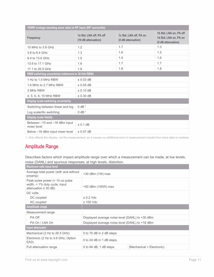
VSWR (voltage standing wave ratio) at RF Input (95th percentile)
Frequency 1a Std, LNA off, PA off (10 dB attenuation)
1c Std, LNA off, PA on (0 dB attenuation)
1b Std, LNA on, PA off 1d Std, LNA on, PA on (0 dB attenuation)
10 MHz to 3.6 GHz 1.2 1.7 1.3
3.6 to 8.4 GHz 1.3 1.6 1.5
8.4 to 13.6 GHz 1.5 1.6 1.6
13.6 to 17.1 GHz 1.6 1.7 1.7
17.1 to 26.5 GHz 1.8 1.8 1.8 RBW switching uncertainty (reference to 30 kHz RBW)
1 Hz to 1.5 MHz RBW ± 0.03 dB
1.6 MHz to 2.7 MHz RBW ± 0.05 dB
3 MHz RBW ± 0.10 dB
4, 5, 6, 8, 10 MHz RBW ± 0.30 dB Display scale switching uncertainty
Switching between linear and log 0 dB 1
Log scale/div switching 0 dB 1 Display scale fidelity Between –10 and –18 dBm input mixer level ± 0.1 dB
Below –18 dBm input mixer level ± 0.07 dB
1. Only affects the display, not the measurement, so it causes no additional error in measurement results from trace data or markers.
Amplitude Range Describes factors which impact amplitude range over which a measurement can be made; at low levels, noise (DANL) and spurious responses; at high levels, distortion. Maximum safe input level Average total power (with and without preamp) +30 dBm (1W) max
Peak pulse power (< 10 us pulse width, < 1% duty cycle, input attenuation ≥ 30 dB)
+50 dBm (100W) max
DC volts DC coupled AC coupled
± 0.2 Vdc ± 100 Vdc
Amplitude range
Measurement range PA Off Displayed average noise level (DANL) to +30 dBm PA On / LNA On Displayed average noise level (DANL) to +18 dBm Input attenuator
Mechanical (2 Hz to 26.5 GHz) 0 to 70 dB in 2 dB steps Electronic (2 Hz to 3.6 GHz, Option EA3) 0 to 24 dB in 1 dB steps,
Full attenuation range 0 to 94 dB, 1 dB steps (Mechanical + Electronic)

Find us at www.keysight.com Page 12
Preamplifiers (2 stages: LNA and PA) Low-Noise Amplifier (LNA) Pre-Amplifier (PA) Option P08 20 MHz to 8.4 GHz 9 kHz to 8.4 GHz Option P13 20 MHz to 13.6 GHz 9 kHz to 13.6 GHz Option P26 20 MHz to 26.5 GHz 9 kHz to 26.5 GHz Noise figure, LNA 4 to 8 dB (nom) 10 dB (nom) Gain 20 dB (nom) 30 dB (nom) Display range
Log scale 0.1 to 1 dB/division in 0.1 dB steps 1 to 20 dB/division in 1 dB steps (10 display divisions) Linear scale 10 divisions Scale units dBm, dBmV, dBμV, dBmA, dBμA, V, W, A
DANL (Displayed Average Noise Level)
DANL defined as average indicated power, using RMS detection, with input terminated in 50 Ohm, and Attenuation set to 0 dB; normalized to a 1 Hz bandwidth.
1a. Standard path (swept, preselector on, LNA off, PA off)
Noise Floor Extension (Option NF2) improves DANL by 8 to 12 dB, for standard path.
Frequency 20 °C to 30 °C Full range Typical
< 10 Hz –125 dBm (nom)
10 to 100 Hz –127 dBm (nom)
100 Hz to 1 kHz –129 dBm (nom)
1 to 9 kHz –138 dBm (nom)
9 to 100 kHz –141 dBm –141 dBm –146 dBm
100 kHz to 1 MHz –150 dBm –148 dBm –153 dBm
1 to 10 MHz –153 dBm –152 dBm –156 dBm
10 MHz to 1.2 GHz –152 dBm –151 dBm –155 dBm
1.2 to 2.1 GHz –150 dBm –148 dBm –153 dBm
2.1 to 3.6 GHz –148 dBm –147 dBm –150 dBm
3.6 to 6.6 GHz –150 dBm –148 dBm –152 dBm
6.6 to 8.4 GHz –150 dBm –148 dBm –152 dBm
8.4 to 13.6 GHz –147 dBm –146 dBm –151 dBm
13.6 to 17 GHz –147 dBm –146 dBm –151 dBm
17 to 22.5 GHz –146 dBm –144 dBm –150 dBm
22.5 to 26.5 GHz –142 dBm –140 dBm –146 dBm
Find us at www.keysight.com Page 13
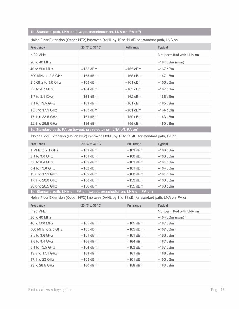
1b. Standard path, LNA on (swept, preselector on, LNA on, PA off)
Noise Floor Extension (Option NF2) improves DANL by 10 to 11 dB, for standard path, LNA on
Frequency 20 °C to 30 °C Full range Typical
< 20 MHz Not permitted with LNA on
20 to 40 MHz –164 dBm (nom)
40 to 500 MHz –165 dBm –165 dBm –167 dBm
500 MHz to 2.5 GHz –165 dBm –165 dBm –167 dBm
2.5 GHz to 3.6 GHz –163 dBm –161 dBm –166 dBm
3.6 to 4.7 GHz –164 dBm –163 dBm –167 dBm
4.7 to 8.4 GHz –164 dBm –162 dBm –166 dBm
8.4 to 13.5 GHz –163 dBm –161 dBm –165 dBm
13.5 to 17.1 GHz –163 dBm –161 dBm –164 dBm
17.1 to 22.5 GHz –161 dBm –159 dBm –163 dBm
22.5 to 26.5 GHz –156 dBm –155 dBm –159 dBm 1c. Standard path, PA on (swept, preselector on, LNA off, PA on)
Noise Floor Extension (Option NF2) improves DANL by 10 to 12 dB, for standard path, PA on.
Frequency 20 °C to 30 °C Full range Typical
1 MHz to 2.1 GHz –163 dBm –163 dBm –166 dBm
2.1 to 3.6 GHz –161 dBm –160 dBm –163 dBm
3.6 to 8.4 GHz –162 dBm –161 dBm –164 dBm
8.4 to 13.6 GHz –162 dBm –161 dBm –164 dBm
13.6 to 17.1 GHz –162 dBm –160 dBm –164 dBm
17.1 to 20.0 GHz –160 dBm –159 dBm –163 dBm
20.0 to 26.5 GHz –156 dBm –155 dBm –160 dBm 1d. Standard path, LNA on, PA on (swept, preselector on, LNA on, PA on) Noise Floor Extension (Option NF2) improves DANL by 9 to 11 dB, for standard path, LNA on, PA on.
Frequency 20 °C to 30 °C Full range Typical < 20 MHz Not permitted with LNA on
20 to 40 MHz –164 dBm (nom) 1
40 to 500 MHz –165 dBm 1 –165 dBm 1 –167 dBm 1
500 MHz to 2.5 GHz –165 dBm 1 –165 dBm 1 –167 dBm 1
2.5 to 3.6 GHz –161 dBm 1 –161 dBm 1 –166 dBm 1
3.6 to 8.4 GHz –165 dBm –164 dBm –167 dBm
8.4 to 13.5 GHz –164 dBm –163 dBm –167 dBm
13.5 to 17.1 GHz –163 dBm –161 dBm –166 dBm
17.1 to 23 GHz –163 dBm –161 dBm –165 dBm
23 to 26.5 GHz –160 dBm –158 dBm –163 dBm
Find us at www.keysight.com Page 14
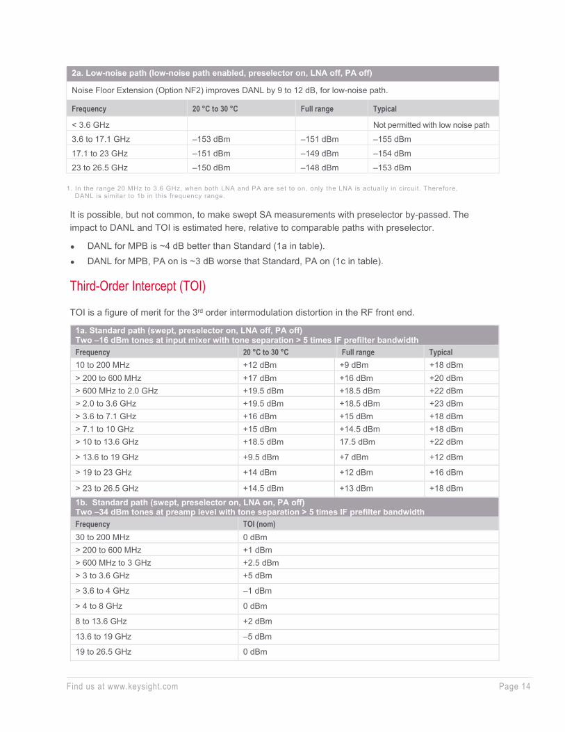
2a. Low-noise path (low-noise path enabled, preselector on, LNA off, PA off)
Noise Floor Extension (Option NF2) improves DANL by 9 to 12 dB, for low-noise path.
Frequency 20 °C to 30 °C Full range Typical
< 3.6 GHz Not permitted with low noise path
3.6 to 17.1 GHz –153 dBm –151 dBm –155 dBm
17.1 to 23 GHz –151 dBm –149 dBm –154 dBm
23 to 26.5 GHz –150 dBm –148 dBm –153 dBm
1. In the range 20 MHz to 3.6 GHz, when both LNA and PA are set to on, only the LNA is actually in circuit. Therefore, DANL is similar to 1b in this frequency range.
It is possible, but not common, to make swept SA measurements with preselector by-passed. The impact to DANL and TOI is estimated here, relative to comparable paths with preselector.
• DANL for MPB is ~4 dB better than Standard (1a in table).
• DANL for MPB, PA on is ~3 dB worse that Standard, PA on (1c in table).
Third-Order Intercept (TOI)
TOI is a figure of merit for the 3rd order intermodulation distortion in the RF front end.
1a. Standard path (swept, preselector on, LNA off, PA off) Two –16 dBm tones at input mixer with tone separation > 5 times IF prefilter bandwidth Frequency 20 °C to 30 °C Full range Typical 10 to 200 MHz +12 dBm +9 dBm +18 dBm > 200 to 600 MHz +17 dBm +16 dBm +20 dBm > 600 MHz to 2.0 GHz +19.5 dBm +18.5 dBm +22 dBm > 2.0 to 3.6 GHz +19.5 dBm +18.5 dBm +23 dBm > 3.6 to 7.1 GHz +16 dBm +15 dBm +18 dBm > 7.1 to 10 GHz +15 dBm +14.5 dBm +18 dBm > 10 to 13.6 GHz +18.5 dBm 17.5 dBm +22 dBm
> 13.6 to 19 GHz +9.5 dBm +7 dBm +12 dBm
> 19 to 23 GHz +14 dBm +12 dBm +16 dBm
> 23 to 26.5 GHz +14.5 dBm +13 dBm +18 dBm 1b. Standard path (swept, preselector on, LNA on, PA off) Two –34 dBm tones at preamp level with tone separation > 5 times IF prefilter bandwidth Frequency TOI (nom) 30 to 200 MHz 0 dBm > 200 to 600 MHz +1 dBm > 600 MHz to 3 GHz +2.5 dBm > 3 to 3.6 GHz +5 dBm
> 3.6 to 4 GHz –1 dBm
> 4 to 8 GHz 0 dBm
8 to 13.6 GHz +2 dBm
13.6 to 19 GHz –5 dBm
19 to 26.5 GHz 0 dBm

Find us at www.keysight.com Page 15
1c. Standard path (swept, preselector on, LNA off, PA on) Two –34 dBm (10 MHz to 3.6 GHz) or –50 dBm (3.6 to 26.5 GHz) tones at preamp level with tone separation > 5 times IF prefilter bandwidth Frequency TOI (nom) 10 to 200 MHz +2 dBm
> 200 to 400 MHz +3 dBm
> 400 MHz to 1 GHz +4 dBm
> 1 to 3.6 GHz +5 dBm
> 3.6 to 4 GHz –14 dBm
> 4 to 8 GHz –13 dBm
> 8 to 13.6 GHz –8 dBm
> 13.6 to 19 GHz –17 dBm
> 19 to 26.5 GHz –12 dBm 1d. Standard path (swept, preselector on, LNA on, PA on) Two –50 dBm tones at preamp level with tone separation > 5 times IF prefilter bandwidth Frequency TOI (nom)
3.6 to 4 GHz –22 dBm
4 to 8 GHz –20 dBm
8 to 13.6 GHz –16 dBm
13.6 to 19 GHz –24 dBm
19 to 26.5 GHz –21 dBm 2a. Low-noise path (swept, Low-noise path enable, preselector on, LNA off, PA off) Two –16 dBm tones at input mixer with tone separation > 5 times IF prefilter bandwidth Frequency 20 °C to 30 °C Full range Typical 3.6 to 7.6 GHz +10 dBm +9 dBm +13 dBm > 7.6 to 10 GHz +11 dBm +10 dBm +14 dBm
> 10 to 13.6 GHz +12 dBm +11 dBm +15 dBm
> 13.6 to 19 GHz +4 dBm +2 dBm +7 dBm
> 19 to 23 GHz +7 dBm +6 dBm +10 dBm
> 23 to 26.5 GHz +8 dBm +6 dBm +10 dBm

Find us at www.keysight.com Page 16
Second-Harmonic Intercept (SHI) SHI is a figure of merit for analyzer distortion at the 2nd harmonic of input signal. Frequency refers to the fundamental signal and extends to ½ the maximum measurable frequency; the 2nd harmonic is at 2*Freq.
1a. Standard path (swept, preselector on, LNA off, PA off)
Frequency of the fundamental Mixer level Distortion SHI 10 MHz to 500 MHz –15 dBm –65 dBc +50 dBm
> 500 MHz to 1.8 GHz –15 dBm –60 dBc +45 dBm
> 1.8 to 3 GHz –15 dBm –77 dBc +62 dBm
> 3 to 4.5 GHz –15 dBm –76 dBc +61 dBm
> 4.5 to 6.5 GHz –15 dBm –77 dBc +62 dBm
> 6.5 to 10 GHz –15 dBm –80 dBc +65 dBm
> 10 to 13.25 GHz –15 dBm –80 dBc +65 dBm 1b. Standard path (swept, preselector on, LNA on, PA off) Preamp Level = Input Level – Input Attenuation Frequency of the fundamental Preamp level Distortion (nom) SHI (nom) 15 to 40 MHz –45 dBm –65 dBc +20 dBm
> 40 MHz to 1 GHz –45 dBm –63 dBc +18 dBm
> 1 to 1.8 GHz –45 dBm –61 dBc +16 dBm
> 1.8 to 13.25 GHz –45 dBm –63 dBc +18 dBm 1c. Standard path (swept, preselector on, LNA off, PA on) Preamp Level = Input Level – Input Attenuation Frequency of the fundamental Preamp level Distortion (nom) SHI (nom) 10 to 400 MHz –45 dBm –78 dBc +33 dBm
> 400 MHz to 1.8 GHz –45 dBm –73 dBc +28 dBm
> 1.8 to 4 GHz –50 dBm –55 dBc +5 dBm
> 4 to 13.25 GHz –50 dBm –60 dBc +10 dBm 1d. Standard path (swept, preselector on, LNA on, PA on) Preamp Level = Input Level – Input Attenuation Frequency of the fundamental Preamp level Distortion (nom) SHI (nom) 1.8 to 4 GHz –50 dBm –44 dBc –6 dBm
4 to 13.25 GHz –50 dBm –47 dBc –3 dBm 2a. Low-noise path: SHI (swept, Low-noise path enable, preselector on, LNA off, PA off)
Frequency of the fundamental Mixer level Distortion SHI 1.8 to 2.5 GHz –15 dBm –95 dBc +80 dBm
> 2.5 to 10 GHz –15 dBm –101 dBc +86 dBm
> 10 to 13.25 GHz –15 dBm –101 dBc +86 dBm

Find us at www.keysight.com Page 17
Gain Compression Standard path: 1 dB gain compression (swept, standard, preselector on, LNA off) (nom)
Frequency Gain Comp PA off (1a)
Gain Comp PA on (1c)
20 to 40 MHz +3 dBm –13 dBm 40 MHz to 3.6 GHz +6 dBm –13 dBm 3.6 to 13.5 GHz +5 dBm 13.5 to 26.5 GHz +1 dBm
Residuals, Images, and Spurious Responses Residual responses (input terminated, 0 dB attenuation)
200 kHz to 8.4 GHz (swept) –100 dBm Zero span or FFT or other frequencies –100 dBm (nom) Image responses (standard path, LNA off, PA off, mixer level = –10 dBm)
Tuned Freq (f) Excitation Freq Full range Typical 10 MHz to 26.5 GHz f+45 MHz –80 dBc –105 dBc 10 MHz to 3.6 GHz f+10,245 MHz –80 dBc –106 dBc 10 MHz to 3.6 GHz f+645 MHz –80 dBc –101 dBc > 3.6 to 13.6 GHz f+645 MHz –78 dBc –87 dBc > 13.6 to 17.1 GHz f+645 MHz –74 dBc –84 dBc > 17.1 to 22 GHz f+645 MHz –70 dBc –82 dBc > 22 to 26.5 GHz f+645 MHz –68 dBc –75 dBc Other spurious responses (input-related, standard path, LNA off, PA off) Mixer level Response First RF order (f ≥ 10 MHz from carrier) –10 dBm –80 dBc + 20 x log(N 1), including IF
feedthrough, LO harmonic mixing responses
Higher RF order (f ≥ 10 MHz from carrier) –40 dBm –80 dBc + 20 x log(N 1), including higher order mixer responses
LO-related spurious responses (Offset from carrier 200 Hz to 10 MHz)
–10 dBm –68 dBc 2 + 20 x log(N 1) –72 dBc 2 + 20 x log(N 1) (typ)
Close-in sidebands spurious response (LO related, offset < 200 MHz)
−73 dBc 2 + 20 × log(N 1) (nom)
1. N is the LO multiplication factor 2. Nominally −40 dBc under large magnetic (0.38 Gauss rms) or vibrational (0.21 g rms) environmental stimuli.
Performance is nominally the same, with PA on, and in low-noise path (LNP).

Find us at www.keysight.com Page 18
Phase Noise (SSB) Phase noise Offset 20-30 °C 0-55 °C Noise sidebands (CF = 1 GHz)
10 Hz Wide Ref Loop BW Narrow Ref Loop BW
–93 dBc/Hz (typ) 1
–88 dBc/Hz (nom) 100 Hz –107 dBc/Hz –107 dBc/Hz –112 dBc/Hz (typ)
1 kHz −125 dBc/Hz –124 dBc/Hz –129 dBc/Hz (typ)
10 kHz –134 dBc/Hz –132 dBc/Hz –136 dBc/Hz (typ)
100 kHz –139 dBc/Hz –138 dBc/Hz –141 dBc/Hz (typ)
1 MHz –145 dBc/Hz –144 dBc/Hz –146 dBc/Hz (typ)
10 MHz –154 dBc/Hz –154 dBc/Hz –157 dBc/Hz (typ)
1. The factory test line l imit is consistent with a warranted specification of –90 dBc/Hz.

Find us at www.keysight.com Page 19
Wide-Bandwidth IQ Analysis (Demod) Several wide-bandwidth IF paths and digitizers are available to acquire IQ data, with LO tuning fixed (not swept), typically to characterize the modulation quality of intentional transmitters (e.g. EVM).
All specifications based on preselector by-passed (RF Path either Microwave Preselector Bypass or Full Bypass) (except <3.6 GHz), unless otherwise noted.
Bandwidth
Bandwidth option 1 IF path name Analysis bandwidth or span range, max Supplemental Information
Standard 10 MHz 10 MHz Standard 25 MHz 25 MHz Licensed as B25 Standard 40 MHz 40 MHz Licensed as B40 Standard 255 MHz 255 MHz Licensed as B2X R10 1.0 GHz 1.0 GHz R15 1.5 GHz 1.5 GHz R20 2.0 GHz 2.0 GHz
1. IF Paths at 10, 25, 40, and 255 MHz are enabled by any of R10, R15, or R20. Each bandwidth option includes and
enables all others with lesser bandwidth; e.g. instruments with R20 also have R15 and R10 licenses, plus B2X, B40, and B25 paths.

Find us at www.keysight.com Page 20
5GNR EVM Residuals (“Floor”) vs Power (“Bathtub Curves”)
Example measurement results are demonstrations of performance (not specifications). EVM residual plots include contributions from the signal generator; the N9032B signal analyzer alone would have lower residuals (by ~3 dB, if assume equal contributions).
Figure 2. 5G NR FR1, 2.0 GHz carrier, 100 MHz single carrier, 256 QAM, 30 kHz SCS, DC Punc off
Figure 3. 5G NR FR1, 4.5 GHz carrier, 100 MHz single carrier, 256 QAM, 30 kHz SCS, DC Punc off

Find us at www.keysight.com Page 21
10 MHz Analysis Bandwidth
10 MHz analysis bandwidth
Analysis bandwidth range 10 Hz to 10 MHz
Tuning range 2 Hz to 26.5 GHz
In practice, low end of tuning range limited to < (½*BW), by image folding and LO feedthrough. Over-range tuning to 27 GHz allowed, but without corrections, performance not specified
IF frequency (center) 322.5 MHz
IF frequency response and phase linearity, demodulation and FFT response relative to the center frequency (nom)
Center Frequency Preselector IF Freq response IF phase linearity, RMS (nom)
≥ 0.02 GHz, ≤ 3.6 GHz N/A ± 0.20 dB ± 0.10 dB (typ) 0.02 dB RMS (nom)
0.037°
3.6 to 26.5 GHz Off ± 0.25 dB ± 0.10 dB (typ) 0.02 dB RMS (nom)
0.067°
Data Acquisition
Description Data packing Supplemental information
32-bit 64-bit Length (IQ sample pairs) 536 MSa (229 Sa) 268 MSa (228 Sa) 2 GB total memory Sample Rate (IQ Pairs) 1.25 × IFBW ADC Resolution 16 bits
25 MHz Analysis Bandwidth (licensed as Option B25)
25 MHz analysis bandwidth (licensed as Option B25)
Analysis bandwidth range 10 Hz to 25 MHz
Tuning range 2 Hz to 26.5 GHz
In practice, low end of tuning range limited to < (½*BW), by image folding and LO feedthrough. Over-range tuning to 27 GHz allowed, but without corrections, performance not specified
IF frequency (center) 322.5 MHz
IF frequency response and phase linearity, demodulation and FFT response relative to the center frequency (nom)
Center Frequency Preselector IF Freq response IF phase linearity, RMS (nom)
≥ 0.02 GHz, ≤ 3.6 GHz N/A ± 0.30 dB ± 0.20 dB (typ) 0.05 dB RMS (nom)
0.28°
3.6 to 26.5 GHz Off ± 0.40 dB ± 0.20 dB (typ) 0.05 dB RMS (nom)
0.28°
Full scale (ADC clipping)
Mixer Level for IF Gain Low (nom) Mixer Level for IF Gain High (nom) 2 Hz to 26.5 GHz –8 dBm –18 dBm

Find us at www.keysight.com Page 22
Data Acquisition
Description Data packing Supplemental information
32-bit 64-bit Length (IQ sample pairs) 536 MSa (229 Sa) 268 MSa (228 Sa) 2 GB total memory Sample Rate (IQ Pairs) 1.25 × IFBW ADC Resolution 16 bits
40 MHz Analysis Bandwidth (licensed as Option B40)
40 MHz analysis bandwidth (licensed as Option B40) Analysis bandwidth range 10 Hz to 40 MHz
Tuning range 2 Hz to 26.5 GHz
In practice, low end of tuning range limited to < (½*BW), by image folding and LO feedthrough. Over-range tuning to 27 GHz allowed, but without corrections, performance not specified
IF frequency (center) 250 MHz IF frequency response and phase linearity, demodulation and FFT response relative to the center frequency Center Frequency Preselector IF Freq response IF phase linearity, RMS (nom)
≥ 0.03 GHz, ≤ 3.6 GHz N/A ± 0.40 dB ± 0.20 dB (typ) 0.05 dB RMS (nom)
0.32°
3.6 to 26.5 GHz Off ± 0.60 dB ± 0.20 dB (typ) 0.05 dB RMS (nom)
0.32°
Full scale (ADC clipping) Mixer level for IF gain low (nom) Mixer level for IF gain high (nom) 2 Hz to 26.5 GHz –8 dBm –18 dBm
Data acquisition Description Data packing Supplemental information 32-bit 64-bit Length (IQ sample pairs) 536 MSa (229 Sa) 268 MSa (228 Sa) 2 GB total memory Sample Rate (IQ Pairs) 1.25 × IFBW ADC Resolution 12 bits

Find us at www.keysight.com Page 23
255 MHz Analysis Bandwidth (licensed as option B2X)
Specifications on this bandwidth apply with center frequencies of 400 MHz and higher.
255 MHz analysis bandwidth (licensed as Option B2X) Analysis bandwidth range 10 Hz to 255 MHz
Tuning range 2 Hz to 26.5 GHz In practice, low end of tuning range limited to < (½*BW), by image folding and LO feedthrough. Over-range tuning to 27 GHz allowed, but without corrections, performance not specified.
IF frequency (center) 690 MHz ADC sample rate 4.8 GSa/sec ADC resolution 14 bits
Final data format I & Q pairs, 32 bits ea, 64 bits/Sa
IQ-pair sample rate 1.25*BW Capture memory 16 GB Capture time (time record length) 7158 msec at full 255 MHz BW
IF frequency response and phase linearity, demodulation and FFT response relative to the center frequency
Center frequency Preselector IF Freq response RMS (nom)
IF phase linearity RMS (nom)
3.3 to 26.5 GHz Off 0.20 dB 1.50° IF dynamic range SFDR (spurious-free dynamic range) (ADC related spurious)
–78 dBc (nom) Signal at –27 dBFS, anywhere in full IF width
Full scale (ADC clipping) (preselector bypassed, LNA off, PA off) 1
Mixer level for IF gain low (nom) Mixer level for IF gain high (nom) < 3.3 GHz –15 dBm –15 dBm 3.3 to 13.3 GHz –8 dBm –17 dBm 13.3 to 26.5 GHz –10 dBm –17 dBm
1. Full scale (ADC clipping level) is a rough estimate of the signal level at which ADC overload occurs. Actual clipping
levels vary significantly; this is only a guide. Mixer level is RF Input level less attenuation setting.

Find us at www.keysight.com Page 24
1 GHz Analysis Bandwidth (Option R10)
Specifications on this bandwidth apply with center frequencies of 700 MHz and higher
1 GHz analysis bandwidth (Option R10)
Analysis bandwidth range 10 Hz to 1.0 GHz
Tuning range 2 Hz to 26.5 GHz
In practice, low end of tuning range limited to < (½*BW), by image folding and LO feedthrough. Over-range tuning to 27 GHz allowed, but without corrections, performance not specified
IF frequency (center) 690 MHz ADC sample rate 4.8 GSa/sec ADC resolution 14 bits
Final data format I & Q pairs, 32 bits ea, 64 bits/Sa
IQ-pair sample rate 1.25*BW Capture memory 16 GB Capture time (time record length)
1660 ms at full 1.0 GHz BW
Capture time increases with each full power-of-2 decrease in BW
IF frequency response
IF frequency response (amplitude flatness); across 1.0 GHz span; relative to amplitude at center of span; for microwave preselector bypass and full bypass paths, with LNA off or LNA on Microwave preselector bypass Full bypass
< 3.3 GHz ± 0.50 dB (nom), LNA off 1 ± 0.50 dB (nom), LNA on 2 NA
3.3 to 26.5 GHz ± 0.75 dB (nom), LNA off
± 0.75 dB (nom), LNA on ± 1.00 dB (nom), LNA off
± 1.00 dB (nom), LNA on
1. ± 0.75 dB at 1.4 GHz ± 500 MHz 2. ± 0.75 dB at 1.4 GHz ± 500 MHz
IF phase linearity; over 1.0 GHz span; peak-to-peak phase, around best-fit straight-line phase (nom)
< 3.3 GHz 30 deg p-p, 8 deg RMS 3.3 to 26.5 GHz 15 deg p-p, 3 deg RMS
IF dynamic range
SFDR (spurious-free dynamic range) (ADC related spurious)
–61 dBc (nom) Signal at –27 dBFS, anywhere in full IF width
Full scale (ADC clipping) (preselector bypassed, LNA off, PA off) (nom) 1 Mixer level for IF gain Low Mixer level for IF gain High < 3.3 GHz –10 dBm –10 dBm 3.3 to 13.3 GHz –8 dBm –17 dBm 13.3 to 26.5 GHz –10 dBm –17 dBm TOI (3rd-order intermodulation distortion, in the IF; 2 tones of equal level, –27 dBFS, 10 MHz tone separation; preselector bypass, IF Gain high) (nom) < 3.3 GHz –74 dBc 3.3 to 20 GHz –74 dBc 20 to 26.5 GHz –72 dBc

Find us at www.keysight.com Page 25
1. Full scale (ADC clipping level) is a rough estimate of the signal level at which ADC overload occurs. Actual clipping
levels vary significantly; this is only a guide. Mixer level is RF Input level less attenuation setting. 2. IF noise up to 5.5 dB worse to either side of IF center.
1.5 GHz Analysis Bandwidth (Option R15)
Specifications on this bandwidth apply with center frequencies of 900 MHz and higher.
1.5 GHz analysis bandwidth (Option R15) Analysis bandwidth range 10 Hz to 1.5 GHz Tuning range 2 Hz to 26.5 GHz In practice, low end of tuning range limited to <
(½*BW), by image folding and LO feedthrough. Over-range tuning to 27 GHz allowed, but without corrections, performance not specified
IF frequency (center) 950 (Band 0) or 1200 MHz for Band 1 to 4
ADC sample rate 4.8 GSa/sec ADC resolution 14 bits Final data format I & Q pairs, 32 bits ea, 64 bits/Sa IQ-pair sample rate 1.25*BW Capture memory 16 GB
Capture time (time record length) 894 ms at full 1.5 GHz BW Capture time increases with each full power-
of-2 decrease in bandwidth
IF frequency response Similar to 2 GHz analysis bandwidth at >3.5 GHz See 2 GHz Analysis Bandwidth section below
IF dynamic range Similar to 2 GHz analysis bandwidth at >3.5 GHz See 2 GHz Analysis Bandwidth section below
IF residual responses (relative to Full Scale; input terminated; IF Gain = High) (nom) < 13.3 GHz –93 dBFS 13.3 to 26.5 GHz –89 dBFS RF residual responses (input terminated, but varies with tuning, generally LO-related) (nom) –88 dBm Noise density in IF (characterized at center of RF band, and center of IF 2) (nom) IF gain low IF gain high < 3.3 GHz –149 dBm/Hz –149 dBm/Hz 3.3 to 8.6 GHz –154 dBm/Hz –156 dBm/Hz 8.6 to 13.3 GHz –153 dBm/Hz –154 dBm/Hz 13.3 to 26.5 GHz –149 dBm/Hz –150 dBm/Hz

Find us at www.keysight.com Page 26
2 GHz Analysis Bandwidth (Option R20)
Assumes Microwave Preselector Bypass Path with center frequencies of 3500 MHz and higher, unless otherwise stated.
2 GHz analysis bandwidth (Option R20)
Analysis bandwidth range 10 Hz to 2.0 GHz
Tuning range 3.5 to 26.5 GHz
In practice, low end of tuning range limited to < (½*BW), by image folding and LO feedthrough. Over-range tuning to 27 GHz allowed, but without corrections, performance not specified
IF frequency (center) 1200 MHz ADC sample rate 4.8 GSa/sec ADC resolution 14 bits
Final data format I & Q pairs, 32 bits ea, 64 bits/Sa
IQ-pair sample rate 1.25*bandwidth Capture memory 16 GB Capture time (time record length) 830 ms at full 2.0 GHz BW Capture time increases with each full power-of-2
decrease in bandwidth
IF frequency response
IF frequency response (amplitude flatness); across 2.0 GHz span; relative to amplitude at center of span; for microwave preselector bypass and full bypass paths, with LNA off or LNA on Microwave preselector bypass Full bypass
3.5 to 26.5 GHz ± 0.75 dB (nom), LNA off
± 1.00 dB (nom), LNA on ± 1.00 dB (nom), LNA off 1
± 1.00 dB (nom), LNA on 2
1. ± 2.00 dB at 3.75 GHz ± 500 MHz 2. ± 2.50 dB at 3.75 GHz ± 500 MHz
IF phase linearity; over 2.0 GHz span; peak-to-peak phase, around best-fit straight-line phase (nom)
3.5 to 26.5 GHz 25 deg p-p, 6 deg RMS
IF dynamic range
SFDR (spurious-free dynamic range) (ADC related spurious)
–54 dBc (nom) Signal at –22 dBFS, anywhere in full IF width
Full scale (ADC clipping) (preselector bypassed, LNA off, PA off) (nom) 1
Mixer level for IF Gain Low Mixer level for IF Gain High 3.5 to 26.5 GHz –8 dBm –18 dBm TOI (3rd-order intermodulation distortion, in the IF; 2 tones of equal level, –19 dBFS, 10 MHz tone separation; preselector bypass, IF gain high) (nom)
3.5 to 20 GHz –75 dBc 20 to 26.5 GHz –70 dBc
IF residual responses (input terminated; IF Gain = High) (nom)
3.5 to 26.5 GHz –86 dBFS

Find us at www.keysight.com Page 27
RF residual responses (input terminated, but varies with tuning, generally LO-related) (nom) –80 dBm Noise density in IF (characterized at center of RF band, and center of IF 2) (nom)
IF Gain Low IF Gain High 3.6 to 8.9 GHz –155 dBm/Hz –157 dBm/Hz
8.9 to 26.5 GHz –151 dBm/Hz –151 dBm/Hz 1. Full scale (ADC clipping level) is a rough estimate of the signal level at which ADC overload occurs. Actual clipping levels
vary signif icantly; this is only a guide. Mixer level is RF Input level less attenuation setting. 2. IF noise up to 5.5 dB worse to either side of IF center.
Inputs and Outputs
Front panel
RF input Standard (Option 508, 513, 526) Option C35 (with Option 526 only)
Type-N female, 50 Ω nominal 3.5 mm male, 50 Ω nominal
External mixing (Option EXM)
Connector SMA, female, 50 Ω, nominal Functions LO output, IF input
IF center frequency
322.5 MHz, for IF bandwidth path ≤ 25 MHz 250.0 MHz, for IF bandwidth path = 40 MHz 690.0 MHz, for IF bandwidth path = 255 MHz 690.0 MHz, for IF bandwidth path = 1 GHz
LO output frequency range 3.75 to 14.1 GHz Output Power 3.75 to 8.72 GHz 7.8 to 14.1 GHz
+16 to +17 dBm (nominal) +16 to +17 dBm (nominal)
Internal calibrator output
Cal out SMA female, 10 MHz to 26.5 GHz internal calibrator output Probe power
Voltage/Current +15 Vdc, ± 7% at 150 mA max (nominal) −12.6 Vdc, ± 10% at 150 mA max (nominal) GND
USB ports
Type Description Connector Output Current
Standard (3) Compatible with USB 2.0
USB Type-A female
0.5 A (nom) for ports not marked with lightning bolt 1.2 A (nom) for port marked with lightning bolt
Headphone Jack
Connector Miniature stereo audio jack 3.5 mm

Find us at www.keysight.com Page 28
Rear Panel
10 MHz out
Connector BNC female, 50 Ω (nominal) Output amplitude ≥ 0 dBm (nominal) Frequency 10 MHz × (1+ frequency reference accuracy) Ext ref in
Connector BNC female, 50 Ω (nominal)
Input amplitude range Sine wave: –5 to 10 dBm (nominal) Square wave: 0.2 to 1.5 V peak-to-peak (nominal)
Input frequency 1 to 50 MHz (nominal) (selectable to 1 Hz resolution)
Frequency lock range ± 2 x 10⁻⁶ of specified external reference input frequency Trigger 1 and 2 inputs
Connector BNC female,10 kΩ (nominal) Trigger level range –5 to +5 V Trigger 1 and 2 outputs
Connector BNC female, 50 Ω (nominal) Trigger level range 0 to 5 V (CMOS) (nominal) VGA (monitor output 1)
Connector VGA compatible, 15-pin mini D-SUB Format XGA (60 Hz vertical sync rates, non-interlaced) analog RGB Resolution 1024 x 768 DisplayPort (monitor output 2)
Connector Mini display port Resolution 1024 x 768 Noise source drive +28 V (pulsed)
Connector BNC female Output Voltage On 28.0 ± 0.1 V Output Voltage Off < 1.0 V SNS series noise source For use with Keysight Technologies SNS series noise sources
Connector 12 pin circular Analog out
Connector BNC female, 50 Ω (nominal) USB ports
USB 3.0 (host, superspeed; 2 ports) Standard Compatible with USB 3.0 Connector USB Type-A female Output current 0.9 A (nominal) USB 2.0 (1 port) Standard Compatible with USB 2.0 Connector USB Type-A female Output current 0.5 A (nominal)
Find us at www.keysight.com Page 29
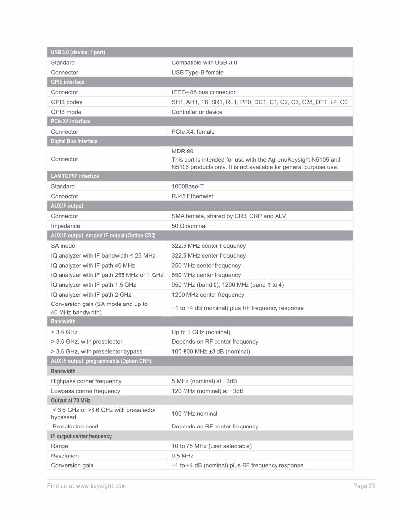
USB 3.0 (device; 1 port)
Standard Compatible with USB 3.0 Connector USB Type-B female GPIB interface
Connector IEEE-488 bus connector GPIB codes SH1, AH1, T6, SR1, RL1, PP0, DC1, C1, C2, C3, C28, DT1, L4, C0 GPIB mode Controller or device PCIe X4 interface
Connector PCIe X4, female Digital Bus interface
Connector MDR-80 This port is intended for use with the Agilent/Keysight N5105 and N5106 products only. It is not available for general purpose use.
LAN TCP/IP interface
Standard 1000Base-T Connector RJ45 Ethertwist AUX IF output
Connector SMA female, shared by CR3, CRP and ALV Impedance 50 Ω nominal AUX IF output, second IF output (Option CR3)
SA mode 322.5 MHz center frequency IQ analyzer with IF bandwidth ≤ 25 MHz 322.5 MHz center frequency IQ analyzer with IF path 40 MHz 250 MHz center frequency IQ analyzer with IF path 255 MHz or 1 GHz 690 MHz center frequency IQ analyzer with IF path 1.5 GHz 950 MHz (band 0), 1200 MHz (band 1 to 4) IQ analyzer with IF path 2 GHz 1200 MHz center frequency Conversion gain (SA mode and up to 40 MHz bandwidth)
−1 to +4 dB (nominal) plus RF frequency response
Bandwidth
< 3.6 GHz Up to 1 GHz (nominal) > 3.6 GHz, with preselector Depends on RF center frequency > 3.6 GHz, with preselector bypass 100-800 MHz ±3 dB (nominal) AUX IF output, programmable (Option CRP)
Bandwidth Highpass corner frequency 5 MHz (nominal) at −3dB Lowpass corner frequency 120 MHz (nominal) at −3dB Output at 70 MHz < 3.6 GHz or >3.6 GHz with preselector bypassed 100 MHz nominal
Preselected band Depends on RF center frequency IF output center frequency Range 10 to 75 MHz (user selectable) Resolution 0.5 MHz Conversion gain –1 to +4 dB (nominal) plus RF frequency response

Find us at www.keysight.com Page 30
Lower output frequencies Subject to folding Residual output signals ≤ −88 dBm (nominal) AUX IF output, Fast Log Video (Option ALV)
General port specifications Connector SMA female Shared with other options
Impedance 50 Ω nominal Fast Log Video Output Output voltage Open-circuit voltages Maximum 1.6 V at –10 dBm nominal Slope 25 ± 1 mV/dB nominal Y-axis video output (Option YAV)
General port specifications Connector BNC female Shared with other options
Impedance 50 Ω nominal Screen video Operating conditions Display scale types Log or Lin “Lin” is linear in voltage Log scales All (0.1 to 20 dB/div) Modes Spectrum analyzer only Gating Gating must be off Output scaling 0 to 1.0 V open circuit, representing bottom to top of screen Offset ± 1% of full scale (nominal) Gain accuracy ± 1% of output voltage (nominal) Log video (log envelope) output Amplitude range (terminated with 50 Ω) Maximum 1.0 V (nominal) for –10 dBm at the mixer Scale factor Output changes 1 V per 192.66 dB change in the signal envelope Bandwidth Set by RBW Operating conditions Select Sweep Type = Swept Linear video (AM demod) output Amplitude range (terminated with 50 Ω) Maximum 1.0 V (nominal) for signal envelope at the reference level Minimum 0 V
Scale factor If carrier level is set to half the reference level in volts, the scale factor is 200% of carrier level per volt. Regardless of the carrier level, the scale factor is 100% of reference level per volt.
Bandwidth Set by RBW Operating conditions Select Sweep Type = Swept

Find us at www.keysight.com Page 31
General Specifications Temperature range
Operating Altitude ≤ 2,300 m
Altitude = 4,600 m Derating
0 to 55 °C 0 to 47 °C The maximum operating temperature derates linearly from altitude of 4,600 m to 2,300 m
Storage –40 to +70 °C Altitude 4,600 m (approx. 15,000 feet)
Maximum Relative humidity
95% RH for temperatures up to 40 °C, decreasing linearly to 45% RH at 55 °C. From 40 °C to 55 °C, the maximum % Relative Humidity follows the line of constant dew point.
Environment
Indoor use Power requirements
Voltage and frequency (nominal) 100/120 V, 50/60/400 Hz 220/240 V, 50/60 Hz
The instruments can operate with mains supply voltage fluctuations up to ± 10% of the nominal voltage
Power consumption, On 630W maximum Power Consumption, Standby 45 W Display
Resolution 1280 x 768 Size 269 mm (10.6 in.) diagonal (nominal) capacitive multi-touch screen Data storage
Internal Removable solid-state drive with 256GB (256GB Micron 1300 2.5-in SSD) External Supports USB 3.0/2.0 compatible memory devices Weight (without options)
Net 27 kg (59 lbs) (nominal) Shipping 39 kg (86 lbs) (nominal) Dimensions
Height 177 mm (7.0 in) Width 426 mm (16.8 in) Length 556 mm (21.9 in)
CPU Modular, upgradeable; Intel i7, 6-core, 1.9 GHz clock, 32 GB DDR4 DRAM; includes secure memory for instrument calibration data
Operating system Windows-10, Enterprise Calibration cycle The recommended calibration cycle is one year; calibration services are available through Keysight service centers.

Find us at www.keysight.com Page 32
Regulatory Information This product is designed for use in INSTALLATION CATEGORY II and POLLUTION DEGREE 2 and MEASUREMENT CATEGORY NONE per IEC 61010 3rd ed, and 664 respectively.
This product has been designed and tested in accordance with accepted industry standards, and has been supplied in a safe condition. The instruction documentation contains information and warnings which must be followed by the user to ensure safe operation and to maintain the product in a safe condition.
This product is intended for indoor use.
Regulatory information
The CE mark is a registered trademark of the European Community (if accompanied by a year, it is the year when the design was proven). This product complies with all relevant directives.
[email protected] The Keysight email address is required by EU directives applicable to our product.
CAN ICES/NMB-001(A) “This ISM device complies with Canadian ICES-001.” “Cet appareil ISM est conforme a la norme NMB du Canada.”
ISM 1-A (GRP.1 CLASS A) This is a symbol of an Industrial Scientific and Medical Group 1 Class A product. (CISPR 11, Clause 4)
The CSA mark is a registered trademark of the CSA International.
The RCM mark is a registered trademark of the Australian Communications and Media Authority.
UK conformity mark is a UK government owned mark. When affixed to the product is declaring all applicable Directives and Regulations have been met in full.
This symbol indicates separate collection for electrical and electronic equipment mandated under EU law as of August 13, 2005. All electric and electronic equipment are required to be separated from normal waste for disposal (Reference WEEE Directive 2002/96/EC).
China RoHS regulations include requirements related to packaging, and require compliance to China standard GB18455-2001.
Find us at www.keysight.com Page 33
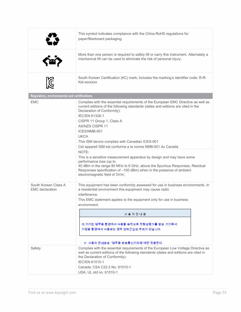
This symbol indicates compliance with the China RoHS regulations for paper/fiberboard packaging.
More than one person is required to safely lift or carry this instrument. Alternately a mechanical lift can be used to eliminate the risk of personal injury.
South Korean Certification (KC) mark; includes the marking’s identifier code: R-R-Kst-xxxxxxx
Regulatory, environmental and certifications EMC Complies with the essential requirements of the European EMC Directive as well as
current editions of the following standards (dates and editions are cited in the Declaration of Conformity): IEC/EN 61326-1 CISPR 11 Group 1, Class A AS/NZS CISPR 11 ICES/NMB-001 UKCA This ISM device complies with Canadian ICES-001 Cet appareil ISM est conforme a la norme NMB-001 du Canada NOTE: This is a sensitive measurement apparatus by design and may have some performance loss (up to 40 dBm in the range 80 MHz to 6 GHz; above the Spurious Responses, Residual Responses specification of –100 dBm) when in the presence of ambient electromagnetic field of 3V/m.
South Korean Class A EMC declaration
This equipment has been conformity assessed for use in business environments. In a residential environment this equipment may cause radio interference. This EMC statement applies to the equipment only for use in business environment.
Safety Complies with the essential requirements of the European Low Voltage Directive as
well as current editions of the following standards (dates and editions are cited in the Declaration of Conformity): IEC/EN 61010-1 Canada: CSA C22.2 No. 61010-1 USA: UL std no. 61010-1

Find us at www.keysight.com Page 34
Acoustic statement (European Machinery Directive)
Acoustic noise emission LpA < 70 dB Operator position Normal operation mode per ISO 7779 Acoustic noise - more information (Values given are per ISO 7779 standard in the “Operator Sitting” position) Ambient temperature (< 40 °C) Nominally under 55 dBA Sound Pressure. 55 dBA is generally considered suitable for use in quiet office environment Ambient temperature (≥ 40 °C) Nominally under 65 dBA Sound Pressure. 65 dBA is generally considered suitable for use in noisy office environment
Environmental stress Samples of this product have been type tested in accordance with the Keysight Environmental Test Manual and verified to be robust against the environmental stresses of storage, transportation, and end-use; those stresses include, but are not limited to, temperature, humidity, shock, vibration, altitude, and power line conditions; test methods are aligned with IEC 60068-2 and levels are similar to MILPRF-28800F Class 3.
To find a current Declaration of Conformity for a specific Keysight product, go to:
http://www.keysight.com/go/conformity

Find us at www.keysight.com Page 35 This information is subject to change without notice. © Keysight Technologies, 2021, Published in USA, November 4, 2021, 3121-1222.EN
Learn more at: www.keysight.com For more information on Keysight Technologies’ products, applications or services, please contact your local Keysight office. The complete list is available at: www.keysight.com/find/contactus
Additional Resources The N9032B PXA X-Series signal analyzer isn't the only thing that will bring you to RF breakthroughs. Powerful software drives your measurements while finely-tuned hardware takes them to new heights. In order to move the measurement plane to your device under test, reach even higher levels of measurement accuracy, and achieve 2 GHz of signal analysis and generation, the N9032B PXA partners with the:
• PathWave X-Series measurement applications and PathWave Vector Signal Analysis (VSA)
• U9361 RCal receiver calibrator for improved receiver test system accuracy by 10X
• M9383B VXG signal generator for wideband stimulus and response testing
N9032B PXA Signal Analyzer Configuration Guide (3121-1216.EN)
www.keysight.com/find/N9032B