N53 W24700 South Corporate Circle • Sussex, WI 53089 • … · · 2012-05-01ID# M740912 02/08...
28
1 02/08 ID# M740912 Toll-Free Customer Service Number for U.S: 1-800-558-5234, For Canada: 1-800-284-8339, For Europe: 00 800 555 85234 (Sweden: 009 555 85234), For Australia: 1800 632 792 Internet Address: www.spalding.com REQUIRED TOOLS AND MATERIALS: OPTIONAL TOOLS AND MATERIALS: • N53 W24700 South Corporate Circle • Sussex, WI 53089 • U.S.A. READ AND UNDERSTAND OPERATOR'S MANUAL BEFORE USING THIS UNIT. FAILURE TO FOLLOW OPERATING INSTRUCTIONS COULD RESULT IN INJURY OR DAMAGE TO PROPERTY. WARNING! • Two (2) Capable Adults • Tape Measure • Wood Board 6” x 6” (scrap) • Sawhorse or Support Table • Hammer • #2 or #3 Phillips Screwdriver • Safety Glasses • Step Ladder 8ft. (2.4 m) SAND SAND (707 lb.) (707 lb.) (321 kg) (321 kg) Write Model Number From Box Here: • (2 each) Wrenches and/or Socket Wrenches and Sockets (Deep-Well Sockets are Recommended). • Extension is Recommended. • Garden Hose or Sand • Large and Small Adjustable Wrenches © COPYRIGHT 2008 by SPALDING AND/OR 1/2" 9/16" 3/4" 1/2" 9/16" 3/4" This manual, accompanied by sales receipt, should be saved and kept on hand as a convenient reference, as it contains important information about your model. Adult Assembly Required. NBA Arena Portable System
Transcript of N53 W24700 South Corporate Circle • Sussex, WI 53089 • … · · 2012-05-01ID# M740912 02/08...

1 02/08 ID# M740912
Toll-Free Customer Service Number for U.S: 1-800-558-5234,
For Canada: 1-800-284-8339,
For Europe: 00 800 555 85234 (Sweden: 009 555 85234),
For Australia: 1800 632 792
Internet Address: www.spalding.com
REQUIRED TOOLS ANDMATERIALS:
OPTIONAL TOOLSAND MATERIALS:
• N53 W24700 South Corporate Circle • Sussex, WI 53089 • U.S.A.
READ AND UNDERSTAND
OPERATOR'S MANUAL BEFORE
USING THIS UNIT.
FAILURE TO FOLLOW
OPERATING INSTRUCTIONS
COULD RESULT IN INJURY OR
DAMAGE TO PROPERTY.
WARNING!
• Two (2) CapableAdults
• Tape Measure
• Wood Board 6” x 6” (scrap)
• Sawhorse orSupport Table
• Hammer
• #2 or #3 PhillipsScrewdriver
• Safety Glasses
• Step Ladder 8ft.(2.4 m)
SA
ND
SA
ND
(707 lb.)
(707 lb.)
(321 k
g)
(321 k
g)
Write Model Number
From Box Here:
• (2 each) Wrenches and/orSocket Wrenches andSockets (Deep-Well Socketsare Recommended).
• Extension is Recommended.
• Garden Hose or Sand
• Large and Small AdjustableWrenches
© COPYRIGHT 2008 by SPALDING
AND/OR
1/2" 9/16" 3/4"
1/2" 9/16" 3/4"
This manual, accompanied by sales receipt, should be saved and kept on hand as a
convenient reference, as it contains important information about your model.
Adult Assembly Required.
NBA Arena Portable System

2ID# M740912 02/08 www.spalding.com
207876 (3pcs)
205711 (4pcs)206340 (7pcs)
207531 (14pcs)
208008 (1pcs)201651 (8pcs)
AR00002
IDENTIFY HARDWARE CARDS
BASE TO POLE HARDWARE CARDFRONT WHEEL ASSEMBLY
HARDWARE CARD
ELEVATOR TO POLE CONNECTION
HARDWARE CARD
ELEVATOR ARMS
HARDWARE CARD
BA00001
BA00002
EL00001
AR00002
RIM ATTACHMENT
HARDWARE CARD AND BAG
STADIUM AND BOARD PAD
HARDWARE CARD
AC00001
To make the assembly easier we have separated the hardware per section.
Each hardware card is dedicated to a specific assembly area.
Open each individually as you progress through the steps. Do not open them all at once.
207552(1pcs)
600158(4pcs)
292901 222700

3www.spalding.com 02/08 ID# M740912
BEFORE YOU START!
To ensure optimal playability of backboard system, a close tolerance
fit between the elevator components and hardware is required. Test-fit
large bolts into large holes of elevator tubes, backboard brackets, and
triangle plates. Carefully rock them in a circular motion to ream out
any excess paint from holes if necessary.
Not all items pictured are included with every model.
SAFETY INSTRUCTIONS
FAILURE TO FOLLOW THESE SAFETY INSTRUCTIONS MAY RESULT IN SERIOUS INJURY OR
PROPERTY DAMAGE AND WILL VOID WARRANTY.
Owner must ensure that all players know and follow these rules for safe operation of the system.
To ensure safety, do not attempt to assemble this system without following the instructions carefully.
Check entire box and inside all packing material for parts and/or additional instruction material. Before
beginning assembly, read the instructions and identify parts using the hardware identifier and parts list in
this document. Proper and complete assembly, use, and supervision are essential for proper operation and
to reduce the risk of accident or injury. A high probability of serious injury exists if this system is not
installed, maintained, and operated properly.
Most injuries are caused by misuse and/or not following instructions.Use caution when using this system.
• If using a ladder during assembly, use extreme caution.
• Two (2) capable adults are recommended for this operation.
• Check base regularly for leakage. Slow leaks could cause system to tip over unexpectedly.
• Seat the pole sections properly (if applicable). Failure to do so could allow the pole sections
to separate during play and/or transport of the system.
• Climate, corrosion, or misuse could result in system failure.
• Minimum operational height is 6' 6" (1.98 m) to the bottom of backboard.
• This equipment is intended for home recreational use only and NOT excessive competitive
play.
• Read and understand the warning label affixed to pole.
• The life of your basketball pole depends on many conditions. The climate, placement of the
pole, location of the pole, exposure to corrosives such as pesticides, herbicides, or salts are
all important.
• If technical assistance is required, contact Customer Service.
• Adult supervision is recommended when adjusting height.
574090 12/06
MOVING SYSTEM
HEIGHTADJUSTMENT
B
A
Rotate crank handle to raise and lower backboard.
Do not over crankhandle beyond the manufactured height indicator range of 7-1/2 - 10 feet. Damage may be caused to the screw jack’s internal adjustment mechanism if adjusted over 10 or under 7-1/2 feet.
1
3 2
4
1.
2.
3.
4.
5.
Adjust basketball backboard height to lowest postion.
Rotate handle forward until wheels engage ground.
Move basketball system to desired location.
Rotate handle back to original position.
Check system for stability.
53

4ID# M740912 02/08 www.spalding.com
IMPORTANT!
Remove all contents from boxes.
Be sure to check inside pole sections,
hardware and additional parts are packed inside.
WARNING!IF YOUR SYSTEM IS EQUIPPED WITH AN ACRYLIC BACKBOARD, EXAMINE BACKBOARD FOR ANY
DAMAGE THAT MAY HAVE OCCURRED DURING SHIPMENT. CRACKS IN THE BACKBOARD COULD RESULT
IN SUDDEN BREAKAGE. IF BACKBOARD IS DAMAGED IN ANY WAY PRIOR TO OR AFTER ASSEMBLY,
CALL TOLL-FREE NUMBER: U.S. 1-800-558-5234; CANADA: 1-800-284-8339; http://www.spalding.com
NOTICE TO ASSEMBLERSAdult Assembly Required. Dispose of ALL packaging materials promptly. As with all products,
periodically inspect for loose small parts.
Assembled unit MUST be filled with sand or water at ALL times.
ALL basketball systems, including those used for DISPLAYS, MUST be assembled and installedaccording to instructions. Failure to follow instructions could result in SERIOUS INJURY. It is NOT
acceptable to devise a makeshift support system.

5www.spalding.com 02/08 ID# M740912
FRONT VIEW BACK VIEW
Get to know the basic parts of your basketball system...
BACKBOARD
RIM
TOP POLE
ELEVATOR
ASSEMBLY
STADIUM PAD
TOP
STADIUM PAD
BOTTOM
BOTTOM POLE
STRUTS
TOP BASE
BOTTOM
BASE
WHEEL
CARRIAGE
ASSEMBLY
GROUND
RESTRAINT
ROPE

6ID# M740912 02/08 www.spalding.com
TOOLS REQUIRED FOR THIS SECTION
SECTION A: BASE AND POLE ASSEMBLY
9/16” 3/4”
(2) Wrenches
AND/OR
(2) Socket Wrenches and Sockets
Extension
#B8 (1)
#B3 (2)
#B2 (12)#B7 (4)
#B4 (2) #B5 (4) #B6 (1)
Item Qty. Part No. Description
1 1 600076 Top Base
2 1 FR908622 Bottom Pole Section
3 1 FR908661 Top Pole Section
4 2 908459 Strut, Front, 62.75” Long, with Holes
5 2 908699 Strut, Rear, 62.75” Long
B1 4 265523 Bolt, Hex Head, 3/8-16 x 1” Long
B2 12 203309 Washer, Flat, 3/8 x 1 O.D.
Item Qty. Part No. Description
B3 2 203041 Nut, Hex-Flange, 3/8-16
B4 2 203331 Bolt, Hex Head, 3/8-16 x 1.5” Long
B5 4 205593 Lock-nut, Nylon Insert, 3/8-16
B6 1 206340 Lock-nut, Nylon Insert, 1/2-13
B7 4 202602 Lock-washer, 0.375 I.D. x 0.675 O.D.
B8 1 206304 Bolt, Hex Head, 1/2-13 x 6-5/16” Long
HARDWARE LIST AND IDENTIFIER
#B1 (4)
BASE TO POLE HARDWARE CARD
BA00001
9/16” 3/4”

7www.spalding.com 02/08 ID# M740912
2.
1.
202900
202900
203041207585
207692
203309
203331
202602
203309
600200908624
600074
206340
PRE-ASSEMBLED
COMPONENTS
203331
202602
203309
600200
WARNING!
The components in steps 1 - 3
are factory pre-assembled.
CHECK THE PRE-ASSEMBLED
AREAS FOR TIGHTNESS.
If any parts are missing or
damaged please contact our
customer service department to
receive replacement parts (see
page 1 for customer service
information).

8ID# M740912 02/08 www.spalding.com
4. B4
B2 B2
B4
B3
ASSEMBLY REQUIRED
3. 265523265523
202602 202602
203309203309
600075
203309
203309
203309
203309
1
Attach top base (1) to bottom base using bolts (B4),
washers (B2) and nuts (B3).
B2B2
9www.spalding.com 02/08 ID# M740912
5.
6.
Wood Scrap - 6” x 6” minimum
(NOT SUPPLIED)
2
3
TOP
BOTTOM
TOP
BOTTOM
Pole
Identification
Stickers
3
2
Correctly identify each pole section.
IMPORTANT!
THE IDENTIFICATION STICKER
IS LOCATED 5" FROM THE END
OF THE POLE.
WHEN PROPERLY ASSEMBLED,
THE POLE SECTIONS SHOULD
HAVE A 4" MINIMUM OVERLAP,
LEAVING 1" BETWEEN THE
OVERLAPPING POLE AND THE
IDENTIFICATION STICKER.
CAUTION!While maintaining alignment, bounce bottom pole section (2)
into top section (3) using a wood scrap as shown until the
top pole no longer moves toward the pole identification
sticker on the middle pole.
NOTE
ORIENTATION
OF EACH POLE
SECTION.
Position each
pole section so
the words
“REAR” are
aligned on the
same side of the
pole when
assembled.
WARNING!
TWO CAPABLE ADULTS REQUIRED
FOR THIS PROCEDURE. FAILURE TO
FOLLOW THIS WARNING COULD
RESULT IN SERIOUS INJURY
AND/OR PROPERTY DAMAGE.
Bottom
Top
Bottom
Top
2
5"
1"
3

10ID# M740912 02/08 www.spalding.com
7. WARNING!
TWO CAPABLE ADULTS REQUIRED
FOR THIS PROCEDURE. FAILURE TO
FOLLOW THIS WARNING COULD
RESULT IN SERIOUS INJURY
AND/OR PROPERTY DAMAGE.
The flange of the bottom
pole will rest on the nut and
washer of frame plate.
NOTE:
Cutaway Views
Assemble pole to base as shown:
A. Place 4 washers (B2) onto the 4 pre-installed bolts so
they rest on the nuts.
B. Rest pole on the 4 washers (B2).
Allow 4 pre-attached bolts to pass through the 4 holes in
bottom pole flange.
Secure pole assembly to plate with washers (B2) and nuts (B5)
as shown.
B2
B2
B2
B5
A
2
B2
B5
B

11www.spalding.com 02/08 ID# M740912
8.
B6
45
4
5
B8
9.
2
Attach struts (4 and 5) to base frame using
bolts (B1) and lock washers (B7).
Attach struts (4 and 5) to bottom pole (2)
using bolt (B8) and nut (B6).
IMPORTANT!NOTE ORIENTATION OF
STRUTS.
Picture shown is as if
you are facing the front
of the system.
Front struts (4) have
holes in them to attach
the stadium pad. The
rear struts (5) DO NOT
have the holes.
WARNING!
TWO CAPABLE ADULTS REQUIRED
FOR THIS PROCEDURE. FAILURE TO
FOLLOW THIS WARNING COULD
RESULT IN SERIOUS INJURY
AND/OR PROPERTY DAMAGE.
B1
B7
4
4
4
4
5
5
5
5
DO NOT fully tighten
at this time.
NOTE:
Fully tighten all
hardware in step 8
and 9 at this time.
NOTE:
IMPORTANT!NOTE POSITION OF STRUTS
Front struts, with holes (4),
get placed closest to the pole.
B1B7

12ID# M740912 02/08 www.spalding.com
Item Qty. Part No. Description
10 2 600074 Wheel, 6”
11 1 600079 Transport Handle, Plastic
12 1 800373 U-Bracket, Pivot
13 1 908466 Bracket, Wheel
14 1 206948 Bracket, Pivot, Lower
15 1 206956 Disk, Pivot, Plastic
16 1 908513 Cross Member
17 1 206082 Axle, Rod, 20.5” Long
18 2 908460 Tube, Hinged
W1 2 200514 Bolt, Hex Head, 3/8-16 x 3” Long
Item Qty. Part No. Description
W2 12 203041 Nut, Hex-Flange, 3/8-16
W3 4 203232 Washer, Flat
W4 2 265563 Bolt, Hex Head, 3/8-16 x 2.5” Long
W5 1 203330 Bolt, Hex Head, 3/8-16 x 4.5” Long
W6 2 203063 Lock-Nut, 3/8-16
W7 1 206252 Bolt, Hex Head, 3/8-16 x 1” Long
W8 8 203277 Bolt, Carriage, 3/8-16 x 2”
W9 2 207550 Push Caps, Metal,, Wheel Assembly
W10 1 202274 Spacer, 0.379 I.D. x 0.50 O.D. x 3.5” Long
#W1 (2)
#W7 (1)
#W10 (1)
#W4 (2)
#W9 (2)
#W8 (8)#W5 (1)
#W2 (12) #W6 (2)#W3 (4)
TOOLS REQUIRED FOR THIS SECTION
SECTION B: WHEEL CARRIAGE ASSEMBLY
9/16”
9/16”
(2) Wrenches
AND/OR
(2) Socket Wrenches and Sockets
Extension
HARDWARE LIST AND IDENTIFIER
FRONT WHEEL ASSEMBLY HARDWARE
CARD
BA00002

13www.spalding.com 02/08 ID# M740912
W1
1.
W1
W2
W2
W2
W4
W2
W3
W4
W3W3
12
4
W3
416
A. Attach u-bracket (12) to cross member (16) using bolts (W4), washers (W3) and nuts (W2).
B. Secure cross member (16) to front struts (4) using bolts (W1), washer (W3) and nuts (W2)
IMPORTANT!
NOTE ORIENTATION
OF BRACKET (12).
IMPORTANT!
NOTE ORIENTATION
OF STRUT BRACE (16).
16
A
B
12
IMPORTANT!
NOTE ORIENTATION
OF STRUT BRACE (16).
COMPLETED ASSEMBLY

14ID# M740912 02/08 www.spalding.com
3.
18
W8
18
W2W2
W2W2
W813
TO INSTALL SECOND
PUSHNUT:
• Assemble Pushnut,
Wheels, Axle, And
Wheel Bracket As
Shown.
• Support
Pushnut/Axle From
The End With A Block
Of Wood To Install
The Second Pushnut
Onto The Axle.
NOTE:
Wood Block
2.
10
10
13
17
W9
W9
Insert axle (17) through wheel bracket (13). Secure wheels (10) to axle using pushnuts (W9). Carefully
tap pushnuts (W9) onto axle with hammer or mallet.
Secure hinge tubes (18) to wheel bracket (13) using bolts (W8),
and nuts (W2).
W8
IMPORTANT!
NOTE ORIENTATION OF
HINGED TUBES (18).
THE SHORT END OF THE
HINGED TUBES (18) GO
UNDER THE WHEEL
BRACKET (13).
18
10

15www.spalding.com 02/08 ID# M740912
4.
5.
W8
W2
W216
11
Attach transport handle (11) to wheel
assembly using carriage bolts (W8)
and nuts (W2).
Secure lower pivot bracket (14) to
wheel assembly using bolt (W7),
pivot disk (15), lower pivot
bracket (14) and nut (W6). Secure
wheel assembly to u-bracket (12)
using bolt (W5), spacer (W10),
and nut (W6).
IMPORTANT!
DO NOT OVER TIGHTEN
BOLT (W5).
W6
12W10
15
14
W6
W7
W5

16ID# M740912 02/08 www.spalding.com
Item Qty. Part No. Description
20 1 700009 Handle, Screw-Jack
21 1 800972 Screw Jack
22 1 600199 Sleeve, Screw Jack
23 1 600165 Cap, Screw Jack
Item Qty. Part No. Description
24 1 202528 Pin, Handle
E1 1 201518 Bolt, Hex-Head, 5/16-18 x 2.75” Long
E2 1 203099 Lock-Nut, Nylon Insert, 5/16-18
#E2 (1)#E1 (1)
TOOLS REQUIRED FOR THIS SECTION
SECTION C: ELEVATOR ASSEMBLY PART 1
1/2”
1/2”
(2) Wrenches (2) Socket Wrenches
and Sockets
Extension
HARDWARE LIST AND IDENTIFIER
Hammer or
Mallet
ELEVATOR TO POLE CONNECTION
HARDWARE CARD
EL00001
AND/OR

17www.spalding.com 02/08 ID# M740912
1.
E2
E1
22
21
23
24
20
A
C
B
D
A. Securely rest the assembly on sawhorse.
B. Slide screw-jack sleeve (22) over screw jack and attach cap (23) to top end.
C. Attach screw-jack (21, 22, 23) to pole bracket with bolt (E1) and nut (E2) as shown.
D. Attach handle (20) to screw jack with pin (24).

18ID# M740912 02/08 www.spalding.com
Item Qty. Part No. Description
30 1 908508 Elevator Tube, Upper
31 1 908509 Elevator Tube, Lower
32 1 Backboard
33 2 700012 Plug Cap
A1 4 205711 Bolt, Hex-Head, 1/2-13 x 2.25”
Long
Item Qty. Part No. Description
A2 7 206340 Nut, Nylock, 1/2-13
A3 14 207531 Washer, Flat, 1.08” O.D.
A4 8 201651 Bushing, Plastic, 1.13” O.D.
A5 3 207876 Bolt, Hex-Head, 1/2-13 x 8.4” Long
A6 1 208008 Spacer, Metal, 0.53” I.D. x 0.75
O.D.x 5.125” Long
#A2 (7)
#A3 (14)
#A4 (8)
#A6 (1)
#A1 (4)
TOOLS REQUIRED FOR THIS
SECTION
3/4”
3/4”
(2) Wrenches
AND/OR
(2) Socket Wrenches and Sockets
Extension
HARDWARE LIST AND IDENTIFIER
207876 (3pcs)
205711 (4pcs)206340 (7pcs)
207531 (14pcs)
208008 (1pcs)201651 (8pcs)
AR00002
ELEVATOR ARMS
HARDWARE CARD
AR00002
SECTION D: ELEVATOR ASSEMBLY PART 2
#A5 (3)

19www.spalding.com 02/08 ID# M740912
TWO CAPABLE ADULTS
REQUIRED FOR THIS
PROCEDURE. FAILURE TO
FOLLOW THIS WARNING COULD
RESULT IN SERIOUS INJURY
AND/OR PROPERTY DAMAGE.
WARNING!
TIGHTEN BOLT (A5) IN
LOCK NUT (A2) UNTIL
FLUSH (EVEN) WITH LOCK
NUT’S OUTER EDGE.
WARNING!
31
31
30
30
31
31
30
30
COMPLETED ASSEMBLY
A5
A5
A2
A3
A2A4
A4
A4A4
1.
2.
A3A3
A3
While system is still resting on sawhorse,
Identify elevator tubes (30 and 31).
While the system is securely resting on the
sawhorse. Install elevator tubes (30 and 31)
to top pole section (3) as shown.
3

20ID# M740912 02/08 www.spalding.com
4.
A1
A4
A3A3
A3
A3
A2
32
A1
A4
A2
Attach backboard (32) to elevator tubes (30, 31) as shown.
3.A5
A3
A3
A6
A2
While the system is still resting on the sawhorse, install
screw jack assembly to lower elevator tube (31). Secure with
bolt (A5), washers (A3), spacer (A6) and nut (A2).
TWO CAPABLE ADULTS
REQUIRED FOR THIS
PROCEDURE. FAILURE TO
FOLLOW THIS WARNING COULD
RESULT IN SERIOUS INJURY
AND/OR PROPERTY DAMAGE.
WARNING!
TIGHTEN BOLT (A5) IN
LOCK NUT (A2) UNTIL
FLUSH (EVEN) WITH LOCK
NUT’S OUTER EDGE.
WARNING!
TIGHTEN BOLT (A1) IN
LOCK NUT (A2) UNTIL
FLUSH (EVEN) WITH LOCK
NUT’S OUTER EDGE.
WARNING!
21www.spalding.com 02/08 ID# M740912
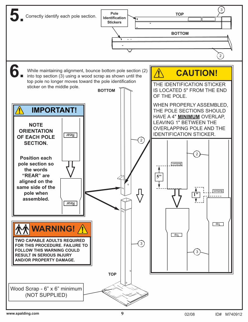
5. A. Fill bottom base half-way with water (approx. 25
gallons (95 Liters)) or sand (approx. 295 of total 590
lbs. (134 of total 268 kg)).
B. Set backboard to the LOWEST elevator setting
C. CAREFULLY upright system.
Make sure that the
anchor rope is centered.
NOTE:
TWO CAPABLE ADULTS
REQUIRED FOR THIS
PROCEDURE. FAILURE TO
FOLLOW THIS WARNING
COULD RESULT IN SERIOUS
INJURY AND/OR PROPERTY
DAMAGE.
ADD TWO GALLONS (7.6
LITERS) OF NON-TOXIC
ANTIFREEZE IN BOTTOM
BASE FOR SUB-FREEZING
CLIMATES.
IF USING SAND: 2 GALLONS
OF ANTI-FREEZE IS NOT
REQUIRED.
CAUTION!
SA
ND
SA
ND
WARNING!
DO NOT LEAVE ASSEMBLY
UNATTENDED WHEN EMPTY;
IT MAY TIP OVER.

22ID# M740912 02/08 www.spalding.com
6. Roll completed assembly to desired
position.
After system is placed in an upright
position, COMPLETE the filling process
in BOTH bases.
If using WATER, the total amounts are
as follows:
Top Base: approx. 9.8 gallons (37.1
liters)
Bottom Base: approx. 49 gallons (186 liters)
If using SAND, the total amounts are as follows:
Top Base: approx. 117 lbs. (53.1 kg)
Bottom Base: approx. 590 lbs. (268 kg)
Rotate caps (33) securely into BOTH bases.
1
33
Make sure that the
anchor rope is centered.
NOTE:
Cap (33) MUST be tightened COMPLETELY
and SECURELY to prevent leakage.
CHECK WATER LEVEL BEFORE EACH
USE! FAILURE TO FOLLOW THIS
WARNING COULD RESULT IN SERIOUS
INJURY AND/OR PROPERTY DAMAGE.
WARNING!
TWO CAPABLE ADULTS
REQUIRED FOR THIS
PROCEDURE. FAILURE TO
FOLLOW THIS WARNING
COULD RESULT IN SERIOUS
INJURY AND/OR PROPERTY
DAMAGE.
ADD ONE GALLONS (7.6
LITERS) OF NON-TOXIC
ANTIFREEZE IN TOP BASE
FOR SUB-FREEZING
CLIMATES.
IF USING SAND: 2 GALLONS
OF ANTI-FREEZE IS NOT
REQUIRED.
CAUTION!S
AN
D
SA
ND
WARNING!
DO NOT LEAVE ASSEMBLY
UNATTENDED WHEN EMPTY;
IT MAY TIP OVER.

23www.spalding.com 02/08 ID# M740912
Sawhorse or Support Table
Item Qty. Part No. Description
32 1 Board
40 1 Rim
41 1 Net
R1 4 600158 Spacer, .87” O.D., 0.50 Long
Item Qty. Part No. Description
R2 1 207552 Foam, 1/16, 3x 4
R3 4 201611 Bolt, Hex-Flange, 5/16-18 x 3” Long
R4 4 203309 Washer, 3/8, 1: O.D.
R5 4 203100 Nut, Hex-Flange, 5/16-18
TOOLS REQUIRED FOR THIS SECTION
SECTION E: ATTACH BOARD RIM
1/2” 9/16”
(2) Wrenches
AND/OR
(2) Socket Wrenches and Sockets
Extension
HARDWARE LIST AND IDENTIFIER
Phillips Screwdriver
#R4 (4)#R1 (4)
#R2 (1)
#R5 (4)
#R3 (4)
RIM ATTACHMENT HARDWARE CARD
AND BAG
207552(1pcs)
600158(4pcs)
222700292901
1/2” 9/16”

24ID# M740912 02/08 www.spalding.com
1.
R1
R5
R5
R1
R3R2
Rim Assembly (40)
Remove screws that secure rim cover.
2. Adjust backboard to lowest setting and attach rim assembly (40) to board using bolts (R3), foam
pad (R2), spacers (R1), washers (R4), and nuts (R5).
Cover Screw
Cover Screw
Rim Cover
R4
R4
Peel off backing of
foam pad and adhere
it to the board before
attaching rim and
spacers.
NOTE:
R2

25www.spalding.com 02/08 ID# M740912
4.
OUTSIDE VIEW
B.
D.C.
A.5.
3.
40
41
41
Install cover plate on rim (40) using self
tapping screws removed in step 1 of
this section (note orientation of cover
plate).
Cover plate will fit
INSIDE back bracket.
NOTE:
Install net (41).
TO ADJUST RIM TENSION
Make adjustments as shown.
Tightening the nut, preloads the spring increases the
rim’s resistance to movement.
• The more the preload, the more force will be required
to move the rim downward.
(9/16”)
LoosenTighten
Rim Cover
40
Cover Screw 220140:
Self-tapping Screw,
1/4-20 x 0.5”
Cover Screw
220140: Self-
tapping Screw,
1/4-20 x 0.5”

26ID# M740912 02/08 www.spalding.com
Item Qty. Part No. Description
50 1 600077 Stadium Pad, Bottom
51 1 600078 Stadium Pad, Top
52 1 203124 Ground Stake
Item Qty. Part No. Description
53 1 574090 Label, Height Adjustment and Moving
P1 10 206011 Bolt, Carriage, 3/8-16 x 2.75” Long
P2 10 203041 Nut, Hex-Flange, 3/8-16
TOOLS REQUIRED FOR THIS SECTION
SECTION F: STADIUM PAD AND FINALIZING SET-UP
9/16”
9/16”
(2) Wrenches
AND/OR
(2) Socket Wrenches and Sockets
Extension
HARDWARE LIST AND IDENTIFIER
#P1 (10)#P2 (10)
STADIUM AND BOARD PAD
HARDWARE CARD
AC00001
27www.spalding.com 02/08 ID# M740912
50
11
51
4
P1
P2
P2
P2
P2
P1
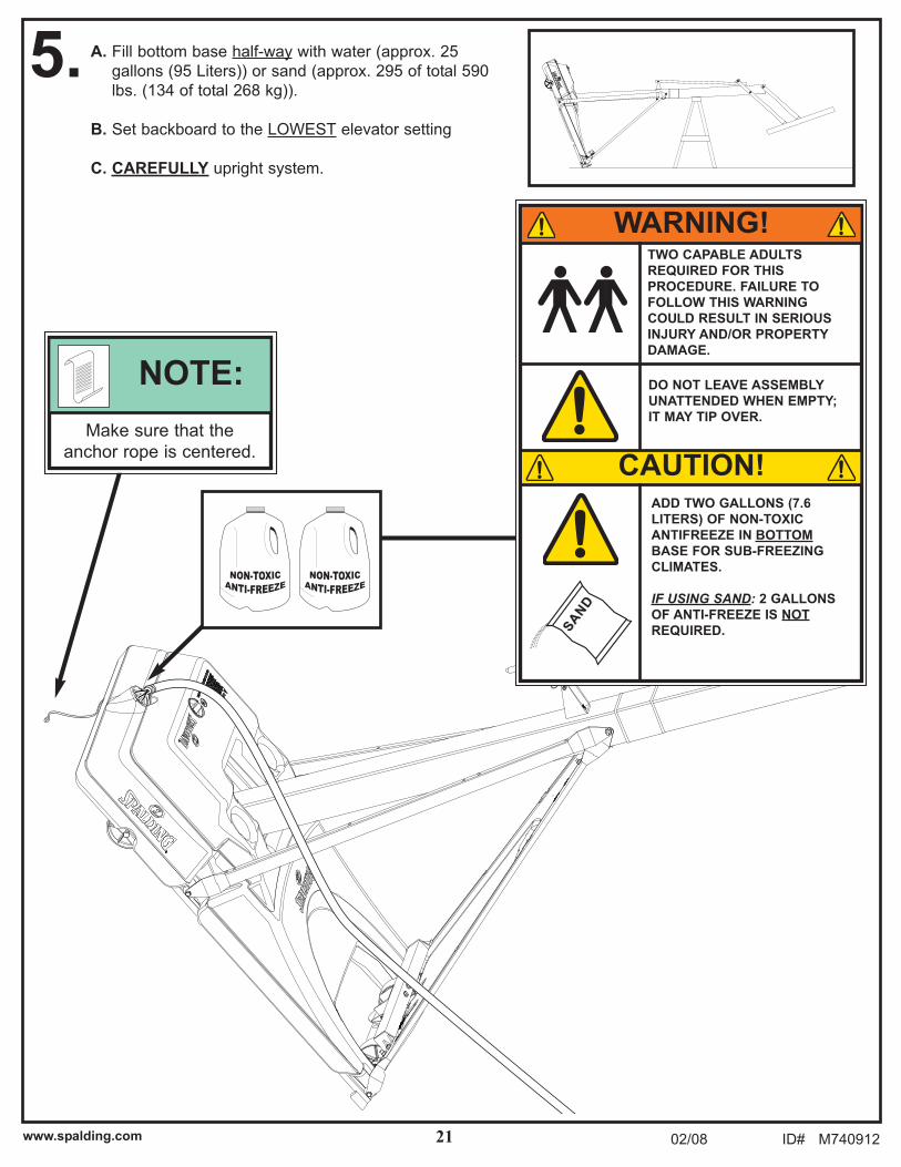
STADIUM PAD - INSTALLATION
1. Attach top stadium pad (51) with bolts (P1)
and Nuts (P2).
2. Slide bottom stadium pad (50) behind the transport
handle (11) and secure with bolts (P1) and nuts (P2).
If necessary, slightly
loosen bolts that
secure front struts
to pole and base
frame (circled
areas).
RE-TIGHTEN after
stadium pads are
attached.
NOTE:

28ID# M740912 02/08 www.spalding.com
52
SECURING SYSTEM WITH GROUND STAKE
3.Secure system by hooking loose end of
rope onto ground stake (52).
Place stake so that when it is screwed into
the ground the rope is taut. DO NOT OVER-CRANK
HANDLE BEYOND THE
MANUFACTURED HEIGHT-
INDICATOR RANGE OF
7-1/2 - 10 FEET. DAMAGE
MAY BE CAUSED TO THE
SCREW JACK’S INTERNAL
ADJUSTMENT MECHANISM
IF ADJUSTED OVER 10 OR
UNDER 7-1/2 FEET.
HEIGHT AND MOVING
LABEL MUST NOT
OBSTRUCT FACTORY
ATTACHED WARNING
LABEL.
B
A
CAUTION!
Official rim height is 10-0’ (3.05 m)
from top of rim to playing surface.
NOTE:
10 ft.
(3.05M)
4. Apply Height Adjustment and Moving
Label (53) to front of pole, where it is
clearly visible.
Handle (20) can be
removed and
stored by removing
pin (24).
NOTE:
24
20
574090 12/06
MOVING SYSTEM
HEIGHTADJUSTMENT
B
A
Rotate crank handle to raise and lower backboard.
Do not over crankhandle beyond the manufactured height indicator range of 7-1/2 - 10 feet. Damage may be caused to the screw jack’s internal adjustment mechanism if adjusted over 10 or under 7-1/2 feet.
1
3 2
4
1.
2.
3.
4.
5.
Adjust basketball backboard height to lowest postion.
Rotate handle forward until wheels engage ground.
Move basketball system to desired location.
Rotate handle back to original position.
Check system for stability.
53
If elevator is hard
to adjust, slightly
loosen bolts
(circled areas).
NOTE: