N1 Service Provisioning System 4.1 User's Guide license from Xerox to the Xerox Graphical User...
202
N1 Service Provisioning System 4.1 User’s Guide 4150 Network Circle Santa Clara, CA 95054 U.S.A. Part No: 817–4822 February 2004
Transcript of N1 Service Provisioning System 4.1 User's Guide license from Xerox to the Xerox Graphical User...

N1 Service Provisioning System4.1 User’s Guide
4150 Network CircleSanta Clara, CA 95054U.S.A.
Part No: 817–4822February 2004

Copyright 2003 Sun Microsystems, Inc. 4150 Network Circle, Santa Clara, CA 95054 U.S.A. All rights reserved.
This product or document is protected by copyright and distributed under licenses restricting its use, copying, distribution, and decompilation. Nopart of this product or document may be reproduced in any form by any means without prior written authorization of Sun and its licensors, if any.Third-party software, including font technology, is copyrighted and licensed from Sun suppliers.
Parts of the product may be derived from Berkeley BSD systems, licensed from the University of California. UNIX is a registered trademark in the U.S.and other countries, exclusively licensed through X/Open Company, Ltd.
Sun, Sun Microsystems, the Sun logo, docs.sun.com, AnswerBook, AnswerBook2, the N1 logo, N1 and N1 Service Provisioning System, EJB, Java,J2EE, IPlanet and Solaris are trademarks, registered trademarks, or service marks of Sun Microsystems, Inc. in the U.S. and other countries. All SPARCtrademarks are used under license and are trademarks or registered trademarks of SPARC International, Inc. in the U.S. and other countries. Productsbearing SPARC trademarks are based upon an architecture developed by Sun Microsystems, Inc. Netscape, Netscape Navigator
The OPEN LOOK and Sun™ Graphical User Interface was developed by Sun Microsystems, Inc. for its users and licensees. Sun acknowledges thepioneering efforts of Xerox in researching and developing the concept of visual or graphical user interfaces for the computer industry. Sun holds anon-exclusive license from Xerox to the Xerox Graphical User Interface, which license also covers Sun’s licensees who implement OPEN LOOK GUIsand otherwise comply with Sun’s written license agreements.
U.S. Government Rights – Commercial software. Government users are subject to the Sun Microsystems, Inc. standard license agreement andapplicable provisions of the FAR and its supplements.
DOCUMENTATION IS PROVIDED “AS IS” AND ALL EXPRESS OR IMPLIED CONDITIONS, REPRESENTATIONS AND WARRANTIES,INCLUDING ANY IMPLIED WARRANTY OF MERCHANTABILITY, FITNESS FOR A PARTICULAR PURPOSE OR NON-INFRINGEMENT, AREDISCLAIMED, EXCEPT TO THE EXTENT THAT SUCH DISCLAIMERS ARE HELD TO BE LEGALLY INVALID.
Copyright 2003 Sun Microsystems, Inc. 4150 Network Circle, Santa Clara, CA 95054 U.S.A. Tous droits réservés.
Ce produit ou document est protégé par un copyright et distribué avec des licences qui en restreignent l’utilisation, la copie, la distribution, et ladécompilation. Aucune partie de ce produit ou document ne peut être reproduite sous aucune forme, par quelque moyen que ce soit, sansl’autorisation préalable et écrite de Sun et de ses bailleurs de licence, s’il y en a. Le logiciel détenu par des tiers, et qui comprend la technologie relativeaux polices de caractères, est protégé par un copyright et licencié par des fournisseurs de Sun.
Des parties de ce produit pourront être dérivées du système Berkeley BSD licenciés par l’Université de Californie. UNIX est une marque déposée auxEtats-Unis et dans d’autres pays et licenciée exclusivement par X/Open Company, Ltd.
Sun, Sun Microsystems, le logo Sun, docs.sun.com, AnswerBook, AnswerBook2, le logo N1, N1 et N1 Service Provisioning System, Java, EJB, J2EE,IPlanet et Solaris sont des marques de fabrique ou des marques déposées, ou marques de service, de Sun Microsystems, Inc. aux Etats-Unis et dansd’autres pays. Toutes les marques SPARC sont utilisées sous licence et sont des marques de fabrique ou des marques déposées de SPARCInternational, Inc. aux Etats-Unis et dans d’autres pays. Les produits portant les marques SPARC sont basés sur une architecture développée par SunMicrosystems, Inc. Netscape, Netscape Navigator
L’interface d’utilisation graphique OPEN LOOK et Sun™ a été développée par Sun Microsystems, Inc. pour ses utilisateurs et licenciés. Sun reconnaîtles efforts de pionniers de Xerox pour la recherche et le développement du concept des interfaces d’utilisation visuelle ou graphique pour l’industriede l’informatique. Sun détient une licence non exclusive de Xerox sur l’interface d’utilisation graphique Xerox, cette licence couvrant également leslicenciés de Sun qui mettent en place l’interface d’utilisation graphique OPEN LOOK et qui en outre se conforment aux licences écrites de Sun.
CETTE PUBLICATION EST FOURNIE “EN L’ETAT” ET AUCUNE GARANTIE, EXPRESSE OU IMPLICITE, N’EST ACCORDEE, Y COMPRIS DESGARANTIES CONCERNANT LA VALEUR MARCHANDE, L’APTITUDE DE LA PUBLICATION A REPONDRE A UNE UTILISATIONPARTICULIERE, OU LE FAIT QU’ELLE NE SOIT PAS CONTREFAISANTE DE PRODUIT DE TIERS. CE DENI DE GARANTIE NES’APPLIQUERAIT PAS, DANS LA MESURE OU IL SERAIT TENU JURIDIQUEMENT NUL ET NON AVENU.
031219@7518

Contents
Preface 11
1 An Overview of the N1 Service Provisioning System Software 15
The Challenges Facing Data Centers 15The N1 Service Provisioning System Software Solution 16The N1 Service Provisioning System Software Architecture 17
Master Server (MS) 19Remote Agent (RA) 20Local Distributor (LD) 21Command Line Interface Client 21Web 21Network Protocols 21Complex Heterogeneous Data Center Environments 23
The N1 Service Provisioning System Software Object Model 25Components 25Plans 29Hosts 30
Object Attributes 31
Approaches to Modeling 31
A Typical J2EE Modeling Process 32
A Typical Windows Modeling Process 33
The N1 Service Provisioning System Software Interfaces 33
The HTML Interface 34
The HTML Interface Navigation 34
The Command Line Interface (CLI) 35
Using the N1 Service Provisioning System Software 38
3

� How to use the HTML User Interface 39� How To Use the Command Line Interface 40
2 Assessing Your Application Environment 43
Preparing to Use the Command Line Interface 43Preparing to Use the HTML User Interface 44Giving Authorized Users Access to the N1 Service Provisioning SystemSoftware 45Managing Hosts 46Managing Applications 46
3 Common Tasks in the HTML User Interface 49
Common Tasks Page 49Windows 49WebLogic 50
Logging in 50� How To Log in 50
Changing Your Password 51� How To Change Your Password from the Log In Page 51� How To Change Your Password from the Users Details Page 51
Logging Out 52� How To Log Out 52
Managing User Accounts and User Groups 52User Groups 52User Accounts 53� How To View User Groups 54� How To Create User Groups 54� How To Edit User Groups 55� How To View User Accounts 56
� How To Create User Accounts 56
� How To Edit User Accounts 57
Summary of CLI Commands for Account Management 58
4 Hosts 61
Working with Hosts 61
Hosts Introduction 61
Physical Hosts 62
4 N1 Service Provisioning System 4.1 User’s Guide • February 2004

Virtual Hosts 62Preparing a Host 62Overview of Managing Hosts 63Locked and Unlocked Hosts 63Hosts and IP Addresses 64The Hosts User Interface 64� How To View Hosts 71� How To View a Host’s Configuration 72� How To Create Hosts 72� How To Edit Hosts 73� How To Hide a Host 74� How To Show a Hidden Host 74Summary of CLI Commands for Hosts 75
Working With Host Types 76The Default Host Type 76Host Type Attributes 77The Host Types User Interface 78� How To View Host Types List 79� How To Viewing Host Types Details 79� How To Create a Host Type 80� How To Edit a Host Type 80Summary of CLI Commands for Host Types 81
Working with Host Sets 81Platform Host Sets 82The Host Sets User Interface 82� How To View Host Sets 84� How To Create Host Sets 84� How To Edit Host Sets 85
Working With Host Searches 86The Host Search User Interface 86� How To View Host Searches 88� How To Create Host Searches 88� How To Edit a Host Searches 89
5 Components 91
Working with Components 91Basic Concepts for Components 91
Contents 5

Modeling Components 92Fully Automated Modeling 92Extending Built-in Resource Types with XML Authoring 93Authoring Component Models in XML 93Overview of Modeling Components 93Building a Component 94Procedures 96Component Inheritance 96Access Modes and Modifiers 96The Component Schema 98Component Variables 99Variable Sets 100Variable Overrides 100Component Reports 100The Components User Interface 101� How To View Components List 107� How To View Components Details 107� How To View A Component’s Installations 108� How To Create Components 108� How To Edit Components 109Where to Find Information Reported by the N1 Service Provisioning SystemSoftware 110Summary of Component CLI Commands 110
Working with Component Types 112Introduction 112Checking In a Component Type 112Extended Control Services 113Built-in Components Types 113Component Type: File 114Component Type: Directory 115IIS Types Introduction 116Component Type: IIS Global Filter Settings 118Component Type: IIS Web Site Filter Settings 119Component Type: IIS Global Settings 119Component Type: COM+ Application 120Component Type: COM Component 122Component Type: Registry Keys 124Component Type: Registry File 125
6 N1 Service Provisioning System 4.1 User’s Guide • February 2004
Component Type: Data Source Name 127
Component Type: Windows Installer File (*.msi) 128
Component Type: Windows Batch File 129
Component Type: Windows Scripting Host Script 130
Component Type: IIS Website (IIS Virtual Directory) 132
Component Type: IIS Website Filter 132
Component Type: Symbolic Link 132
Component Type: WebLogic WAR file 133
Component Type: WebLogic web application settings 133
Component Type: WebLogic Web Application 134
Component Type: WebLogic JAR file 136
Component Type: WebLogic EJB settings 137
Component Type: WebLogic EJB container 137
Component Type: WebLogic EJB 138
Composite Component: WebLogic EJB Container 139
Component Type: WebLogic EAR file 140
Component Type: WebLogic enterprise application settings 141
Component Type: WebLogic Enterprise Application Container 142
Component Type: WebLogic Enterprise Application 143
Component Type: WebLogic List 144
Component Type: Contained WebLogic web Application Container 145
Component Type: contained WebLogic web application 146
Component Type: Contained WebLogic EJB Container 146
Component Type: Contained WebLogic EJB 147
System Components 147
Windows System Service 147
Control Procedures 147
WebLogic Target 148
Procedures 148
Component Type User Interface 148
The Component Type Page 148
The Component Type Details Page 150
The New Component Type Edit Page 150
� How To View Component Types 151
� How To View Component Types Details 151
� How To Create Component Types 152
� How To Edit Component Types 152
General Purpose Extended Control Services 153
Contents 7

Extended Control Services for IIS 154
Extended Control Services for Windows Services 154
6 Plans 155
Working with Plans 155
Plan Types 156
Types of Steps 156
Plan XML Schema 156
Plans User Interface 156
� How To View Plans List 159
� How To View Plan Details 160
� How To Edit Plans 160
How To Create Plans 160
Summary of CLI Commands 162
Session Variables 163
Session Variables User Interface 163
� How To View Session Variables 165
� How To View Session Variables Details 165
� How To Edit Session Variables 165
Running Plans 166
� How To View Running Plans 166
� How To Use a Component’s Direct Run Procedures 166
Summary of CLI Commands 167
7 Comparisons 169
Snapshots 169
How Snapshots Help 170
Types of Comparisons and Their Features 170
Model to Model Comparisons 170
Model-to-Install Comparisons 171
Install-to-Install Comparisons 171
Why Use Scripts in Install-to-Install Comparisons? 172
Using Scripts in Install-to-Install Comparisons 172
Running Comparisons 173
Time Synchronization for Comparisons 173
M-I (Model to Installation) Comparisons 173
Comparisons User Interface 175
8 N1 Service Provisioning System 4.1 User’s Guide • February 2004
� How To View Comparisons List 179
� How To View Comparisons Details 179
� How To Create an M to M Comparison 179
� How To Create an M to I Comparison 180
� How To Create an I to I Comparison 181
� Choosing Directories or Files to Ignore During Comparisons 182
� Removing a Directory or File from the Ignore List 183
� Canceling a System Comparison in Progress 183
Running a Saved Comparison When a Component’s Version has Changed 183
Summary of CLI Commands 184
8 Configuring Notifications 185
Working with Notifications 185
Notifications User Interface 186
� How To View Notifications 188
� How To View Notifications Details 188
� How To Create Notifications 188
Default Event Messages 189
Event Severities 192
Summary of Notification CLI Commands 193
A Special Names 195
Reserved Names 195
Glossary 197
Index 201
Contents 9

10 N1 Service Provisioning System 4.1 User’s Guide • February 2004

Preface
The N1 Service Provisioning System 4.1 User’s Guide introduces you to the product anddescribes how to perform many tasks using the HTML user interface.
Who Should Use This BookThis book is for advanced system administrators who are performing the initialconfiguration of the N1 Service Provisioning System software and for systemadministrators who are responsible for maintaining the system.
This document is intended for experienced system administrators with extensiveknowledge of Sun™ software and hardware. Do not use this document as a planningor pre-sales guide. You should have already determined your system requirementsand purchased the appropriate equipment and software before reading this document.
How This Book Is OrganizedThe N1 Service Provisioning System 4.1 User’s Guide provides an overview of the N1Service Provisioning System software and provides task-based procedures forcommon tasks.
Chapter 1 provides an introduction to the N1 Service Provisioning System software .The product architecture, object model, and interfaces are described.
Chapter 2 prompts you with questions that will aid you in setting up the N1 ServiceProvisioning System software .
11

Chapter 3 provides procedures to perform tasks in the N1 Service Provisioning Systemsoftware ’s HTML user interface.
Chapter 4 provides a description of how the provisioning software interacts withhosts. The chapter also contains procedures on managing hosts with the provisioningsoftware.
Chapter 5 provides conceptual information about what components are, how theywork, and which components are built-in. This chapter also provides procedures forbasic component management tasks.
Chapter 6 describes how to work with plans in the N1 Service Provisioning Systemsoftware .
Chapter 7 describes the types of comparisons that the provisioning software can run.
Chapter 8 provides information on how to set up the N1 Service Provisioning Systemsoftware to notify you when an event occurs.
Appendix A contains a list of names that are restricted to system use only.
Glossary provides a list of words and phrases found in this book and their definitions.
Related BooksThe following books provide conceptual information or procedures to administer theN1 Service Provisioning System software . If you plan to use this documentation in ahardcopy format, ensure that you have the following books available for yourreference.
� N1 Service Provisioning System 4.1 Installation Guide� N1 Service Provisioning System 4.1 Reference Guide� N1 Service Provisioning System 4.1 Release Notes
Accessing Sun Documentation OnlineThe docs.sun.comSM Web site enables you to access Sun technical documentationonline. You can browse the docs.sun.com archive or search for a specific book title orsubject. The URL is http://docs.sun.com.
12 N1 Service Provisioning System 4.1 User’s Guide • February 2004

Ordering Sun DocumentationSun Microsystems offers select product documentation in print. For a list ofdocuments and how to order them, see “Buy printed documentation” athttp://docs.sun.com.
Typographic ConventionsThe following table describes the typographic changes used in this book.
TABLE P–1 Typographic Conventions
Typeface or Symbol Meaning Example
AaBbCc123 The names of commands, files, anddirectories; on-screen computer output
Edit your .login file.
Use ls -a to list all files.
machine_name% you havemail.
AaBbCc123 What you type, contrasted withon-screen computer output
machine_name% su
Password:
AaBbCc123 Command-line placeholder: replace witha real name or value
To delete a file, type rmfilename.
AaBbCc123 Book titles, new words, or terms, orwords to be emphasized.
Read Chapter 6 in User’s Guide.
These are called class options.
You must be root to do this.
Shell Prompts in Command ExamplesThe following table shows the default system prompt and superuser prompt for the Cshell, Bourne shell, and Korn shell.
Preface 13

TABLE P–2 Shell Prompts
Shell Prompt
C shell prompt machine_name%
C shell superuser prompt machine_name#
Bourne shell and Korn shell prompt $
Bourne shell and Korn shell superuser prompt #
14 N1 Service Provisioning System 4.1 User’s Guide • February 2004
CHAPTER 1
An Overview of the N1 ServiceProvisioning System Software
This chapter introduces the N1™ Service Provisioning System software solution formanaging applications in data centers. It discusses the problems that the provisioningsoftware solves. It also describes the provisioning software architecture and theobject-oriented methodology that is applied to application management.
This section discusses the following topics:
� “The Challenges Facing Data Centers” on page 15� “The N1 Service Provisioning System Software Solution” on page 16� “The N1 Service Provisioning System Software Architecture” on page 17� “The N1 Service Provisioning System Software Object Model” on page 25� “Approaches to Modeling” on page 31� “The N1 Service Provisioning System Software Interfaces” on page 33� “Using the N1 Service Provisioning System Software” on page 38
The Challenges Facing Data CentersBusinesses of all kinds depend increasingly on software applications for their coreoperations. Managing these applications is a mission-critical task. Yet, until now, IToperators in data centers have had only rudimentary tools for deploying, configuring,and analyzing applications. Most data centers find themselves relying on customscripts to perform essential functions. IT operators recognize the risk involved withthese scripts:
� Scripts are usually hastily written and are prone to error.� Scripts tend to operate using a long lists of files and lack the ability to manage
applications as discrete units.� Scripts are written with an imperfect knowledge of application requirements,
component dependencies, host environments, and other factors that can affect thesuccess or failure of a deployment.
15

� Scripts lack the benefits of a complete management platform; for example, theytypically can not rollback operations systematically, dynamically adjustconfiguration values, and so on.
The N1 Service Provisioning SystemSoftware SolutionN1 Service Provisioning System software is an enterprise-class software platform thatautomates the deployment, configuration, and analysis of applications in data centers.The provisioning software applies an object-oriented approach to:
� Application components
� Tasks that IT operators perform on application components: deployment,configuration, and analysis.
This object-oriented approach ensures that all the intelligence about an applicationcomponent is automatically taken into account every time that component is actedupon. This consistency makes data center operations more accurate and less prone toerror. Through Application Awareness–knowledge of what an application requires as awhole–IT operators gain unprecedented control over applications and data centeroperations.
N1 Service Provisioning System software can:
� Automate and manage software rollouts, patches, and upgrades� Develop models of your existing deployment processes� Determine what software is installed on your hosts� Compare the configurations of hosts� Monitor and maintain documented and consistent configurations.
N1 Service Provisioning System software offers a full range of features that help makethat task of managing an enterprise wide computing environment easier and faster.
The provisioning software provides:
Automated Deployment End-to-end automation of the deployment process,including distribution, configuration, and startup ofpackaged and custom applications.
Differential Deployment Enabling delta-only distribution of large contentdirectories thereby speeding up deployments significantlyand optimizing incremental directory updates.
Deployment Simulation Complete simulation of deployments to ensure that keyrequirements for success are in place before deployment.
16 N1 Service Provisioning System 4.1 User’s Guide • February 2004

Dynamic Configuration Real-time generation of application configuration for thetarget environment provides flexibility duringdeployment.
Dependency Management Ability to encode application dependency informationwhich is checked during Deployment Simulation toprevent errors that cause downtime and to leverages bestpractices across entire operations team.
Application Comparison Ability to track application configuration drifts, andpinpoint unauthorized changes to servers reduces thetime required for root-cause analysis of application errors.
Version Control Central repository that tracks all deployment andconfiguration data for reference, reconstruction, and toautomate rollback to previous states.
Logging and Reporting Detailed logs of every action taken by the system acrossall applications and managed servers provides completeaudit history of every change made to every server.
Native Windows Support For COM+ components, no XML editing is required inorder to install COM+ components as eitherInteractiveUser or a particular User and Password.
Windows System Reboot Many applications require that a server be rebootedduring or after software installation. Plans include stepsthat can reboot a Microsoft Windows server.
The N1 Service Provisioning SystemSoftware ArchitectureThe N1 Service Provisioning System software is a distributed software platform thatautomates the deployment and configuration tasks in an enterprise wide computingenvironment and provides increased visibility and control of the servers, installedapplications, and file structures.
The provisioning software includes the following special-purpose applications:
� Master Server, a server that hosts the N1 Service Provisioning System softwareapplication. This server stores components and plans and provides an interface formanaging application deployments. There can only be one Master Server within anenterprise.
Chapter 1 • An Overview of the N1 Service Provisioning System Software 17

� Remote Agent, small management applications that perform operations on theindividual host on which it is installed. Every host that is under provisioningsoftware control must have the Remote Agent installed.
� Local Distributors, optional servers that act as a proxy for the Master Server tooptimize network communications across data centers, through firewalls, and toreduce the load on the Gold Server.
� Command Line Interface Client, establishes a communication path to the MasterServer allowing command execution on the Master Server.
� Web Server, establishes a communication path to the Master Server allowingcontrol of the N1 Service Provisioning System software through the use of a webbrowser.
The following illustration shows how an example of how applications might beinstalled on an enterprise network.
18 N1 Service Provisioning System 4.1 User’s Guide • February 2004

TomcatWeb Server
WebBrowser
User System
Master Server
FileSystem
PostgreSQLData Base
TCP/IP
CLIClient
SecureShell
User System
SSH
TCP/IP or SSL
TCP/IP or SSL
RA
Server
RA
Server
RA
Server
RA
Server
RA
Local Distributor
Master Server Application
FIGURE 1–1 The N1 Service Provisioning System Software Architecture.
Master Server (MS)The Master Server is the main processing engine of the N1 Service ProvisioningSystem software . It is installed on a dedicated machine and provides the primaryprocessing engine that drive the various provisioning software functions. The MasterServer houses the database that defines all the objects, object attributes, and plans thatdefine the tasks to be performed. The Master Server also runs a Command LineInterface (CLI) client to provide typed control over the N1 Service ProvisioningSystem software and a web server that provides the HTML (graphical) interface.
Chapter 1 • An Overview of the N1 Service Provisioning System Software 19

The Master Server:
� A database identifying all hosts registered in the provisioning software
� A database of system objects, components, and plans
� Performs version control on the objects stored in the repository
� Authenticates IT operators and ensures that only authorized users perform specificoperations
� Includes special purpose engines for performing tasks such as dependencytracking and deployments
� Provides both an HTML interface and a command-line interface for users
The N1 Service Provisioning System software repository stores components and plansin a secure, embedded SQL relational database accessible only to authorized users.The repository tracks the version of each component and each plan. For example, aspart of a deployment, an IT operator can run plan version 5, which deploys version 3of a Web server and a version 4 of a custom application.
In live data center operations, proposed changes to applications can come from manysources: from the original application development group, from the QA team, andfrom the IT team managing production servers. The provisioning software enables IToperators to capture configuration data from any of these sources and check thesechanges into the repository. IT operators can use the command line interface (CLI) toaccess any machine on the network and capture its configuration data. Alternatively,they can install a Remote Agent on a machine and then use the HTML interface toselect resources from the machine that the provisioning software stores in therepository and combines with configuration data to create a component.
Remote Agent (RA)A Remote Agent is a Java™ application that runs on every system managed by the N1Service Provisioning System software . Its job is to perform the tasks requested by theMaster Server. Because Remote Agents are typically invoked only when application isbeing brought up or taken down, Remote Agents do not compete for resources withapplications on data center servers.
Remote Agents:
� Report server hardware and software configurations to the Master Server� Start and stop services� Manage directory contents and properties� Caches applications and/or directories and files before actual installation� Install and uninstall software� Run OS commands and native scripts specified in component models
20 N1 Service Provisioning System 4.1 User’s Guide • February 2004

Local Distributor (LD)The use of Local Distributors is optional. When used they become a proxy thattemporarily acts as the Master Server to optimizes the distribution and managementof applications, files, and directories.
Data centers can use Local Distributors to:
� Minimize network traffic during deployments. The Master Server can send onecopy of a component to a Local Distributor, which then replicates the componentfor installation on a collection of servers through the use of the Remote Agent.
� Minimize firewall reconfigurations. If a firewall stands between the Master Serverand a collection of servers, administrators can open the firewall just for the serversrunning Local Distributors, rather than for every server involved in a deployment.
� Minimize the load to the Master Server during large scale deployments.
Command Line Interface ClientThe Command-Line Interface Client provides a communication path to the MasterServer to enable the execution of N1 Service Provisioning System software commandsfrom a remote system. These commands are entered using the Windows commandline or a UNIX® shell such as bash. The command-line interface also supports the useof shell scripts using sh or Perl.
The Command-Line Interface Client can also use the Jython programming language.Jython is a Java implementation of the high-level, dynamic, object-oriented languagePython. You should install Jython on any system on which you plan to install theCommand-Line Interface Client. For more information about Jython and to downloadJython, visit http://www.jython.org.
WebThe Web provides a communication path to the Master Server.
Network ProtocolsN1 Service Provisioning System software supports a variety of network protocols forcommunication among the N1 Service Provisioning System software applications. Theprotocols are:
� Raw TCP/IP� Secure Shell (SSH v1 and v2)
Chapter 1 • An Overview of the N1 Service Provisioning System Software 21

� Secure Sockets Layer (SSL)
Raw TCP/IPRaw TCP/IP is standard TCP/IP without additional encryption or authentication. Theadvantage of raw TCP/IP is that it requires no additional set-up and configuration. Ifyour data center network is protected by a firewall and secured from intrusion, usingraw TCP/IP provides a convenient method for communication among N1 ServiceProvisioning System software applications.
Secure Shellssh (Secure Shell) is a UNIX-based command suite and protocol for securely accessinga remote computer. ssh secures network client/server communications byauthenticating both endpoints with a digital certificate and by encrypting passwords.ssh uses RSA public key cryptography to manage connections and authentication.Because it is more secure than telnet or other shell-based communication methods,many system administrators use ssh to manage Web servers and other remotesystems.
The provisioning software can be configured so that its applications communicateusing ssh. N1 Service Provisioning System software supports OpenSSH explicitly.OpenSSH is a free version of ssh that has been primarily developed by the OpenBSDProject. (For more details, see www.openssh.com.) The provisioning software can beconfigured to support other versions of ssh, as well.
Secure Sockets LayerSecure Sockets Layer (SSL) is a protocol for securing communication over IP networks.SSL uses TCP/IP sockets technology to exchange messages between a client and aserver, while protecting the message with a public-and-private key encryption systemdeveloped by RSA. Support for SSL is included in most Web server products, as wellas in the Netscape and Microsoft Web browsers.
N1 Service Provisioning System software applications can be configured to use SSL fortheir network communications, preventing the provisioning software’s messages frombeing read or tampered with. Optionally, N1 Service Provisioning System softwareapplications can be configured to use SSL to authenticate each other beforecommunicating, further increasing network security.
22 N1 Service Provisioning System 4.1 User’s Guide • February 2004

Selecting Protocols to Meet Specific NeedsN1 Service Provisioning System software enables you to select the protocol you willapply to each of the following types of network communication:
� Communication between the Master Server and its children (Local Distributors andRemote Agents)
� Communication between a particular Local Distributor and its children (RemoteAgents)
� Communication between the Master Server and a Command Line Interface Client
You can tailor your network security to meet the needs of your particular networktopology. For example, if communication within each of your data centers is secure,but your network connection to a remote data center passes through the publicInternet, you could configure the Master Server to use SSL when communicating aLocal Distributor installed inside the firewall for the remote data center, so that allcommunication over the Internet is secured. The Local Distributor could use rawTCP/IP to communicate with its children, since all the communication over the localnetwork is secure, and SSL is not required.
For information on configuring SSL and SSH, please see N1 Service ProvisioningSystem 4.1 Installation Guide.
Complex Heterogeneous Data CenterEnvironmentsThe N1 Service Provisioning System software is designed to fit into data centerenvironments and complement the management, monitoring, and control systemsalready in place.
Recognizing the diversity of hardware and software found in most Internet datacenters, the provisioning software has been designed with cross-platform support inmind. It uses standard communication protocols (HTTP, HTTPS, SSH, and TCP/IP)and standard file and presentation formats (HTML and XML), and it works withstandard application architectures (J2EE™ and .Net). It provides data centers with astandards-based system for managing all their applications, whether thoseapplications are UNIX-based or Windows-based.
Supported Operating SystemsYou can install the N1 Service Provisioning System software Master Server on systemsthat are running the following operating systems:
� Solaris 8, Solaris 9
Chapter 1 • An Overview of the N1 Service Provisioning System Software 23

� Red Hat Linux 7.2, 7.3, 8.0 and Red Hat Advanced Server 2.1� Microsoft Windows 2000 Server and Microsoft Windows 2000 Advanced Server
You can install the N1 Service Provisioning System software Remote Agent, LocalDistributor, and CLI Client on systems that are running the following operatingsystems:
� Solaris 2.6, Solaris 7, Solaris 8, Solaris 9� Red Hat Linux 7.2, 7.3, 8.0 and Red Hat Advanced Server 2.1� IBM AIX 4.3.3, 5.1, 5.2� Microsoft Windows 2000 Server and Microsoft Windows 2000 Advanced Server
For more information about system requirements, see the N1 Service ProvisioningSystem 4.1 Installation Guide.
Supported Web BrowsersThe following table summarizes the Web browser requirements for the HTML userinterface.
TABLE 1–1 Web Browser Requirements for the HTML User Interface
Platform Browser
Solaris Netscape 6.2.2, Netscape 7.0
Red Hat Netscape 6, Netscape 7.1
Windows Internet Explorer 5.5 and 6, Netscape 6,Netscape 7.1
Supported LocalesThe N1 Service Provisioning System software has been internationalized to install andrun in localized environments. You will need to adhere to the following requirementsif you want to run the software in a localized environment.
� All applications must be run in the same locale or in locales that are equivalent.The Remote Agent, Local Distributors, and CLI Client must run in the same localeas the Master Server.
� The software accepts only ASCII characters for file names, directory names, andother input.
24 N1 Service Provisioning System 4.1 User’s Guide • February 2004
The N1 Service Provisioning SystemSoftware Object ModelN1 Service Provisioning System software provides an object-oriented methodology formanaging application deployment and configuration. It provides increased visibilityand control of the servers, installed applications, and file structures.
The objects are loosely grouped as infrastructure, main, and supporting. Infrastructureobjects are things like Users, User Groups, Hosts and Host Sets. Main objects arethings like Resources, Components, and plans. Supporting objects are things likeComparisons and Notifications.
ComponentsA component is a logical grouping of source information (software and/or filestructures or other components) that define an application.
The N1 Service Provisioning System software supports two types of components,simple and composite. A simple component is a component that references a singlesource item. The type of source items that simple component references corresponds tothe component’s Component Type. For example, a file, a directory of files, a registrykey, a COM object, a Java™ Archive (JAR), an EAR, an IIS website, etc. A compositecomponent is a component that references other components. Composite componentscan contain any number of simple and/or composite components.
All components, regardless of whether they are simple or composite have thefollowing characteristics in common:
Name A text field that identifies the component. This includes the pathwhere the component is stored.
Type A user definable object (Component Type) that is used to controlhow to handle source information. The component type object isactually another component that manages the acquisition anddeployment of source objects such as files, directories, andconfigurations. The provisioning software comes populated with alarge number of component types that support WebLogic andWindows, UNIX® , and some generic models.
Version The revision number of the component. Each time a component ismodified, the repository increments its version number.
Platform Identifies the platform(s) or operating system(s) that are validtargets for the component’s deployment.
Chapter 1 • An Overview of the N1 Service Provisioning System Software 25

Source Identifies from where the component source information came. Thisinclude the path.
Checked in The date and time when the component was checked in. That is,created or modified.
Checked in by The user ID of the person who checked in the component. Thisprovides an audit trail when trying to troubleshoot problems orinconsistencies.
Label A user definable text string that can be used to control the sortingon the components page.
Description A text string that describes the component object. This attribute isnot used by the provisioning software but can provide meaningfulinformation to the user.
For a more complete description of component attributes see “Building a Component”on page 94.
The N1 Service Provisioning System software stores each component along withmetadata that contains important information about the component, including how to:
� Install and uninstall the component
� Configure the component
� Control the component (e.g., through administration consoles or other interfaces)
� Analyze the component in comparison to other application components (forexample, specifying whether log files and /tmp directories should be considered incomparisons)
� Start up and shut down the component
By reading this metadata and comparing components, the provisioning software canidentify and track dependencies among components.
Figure 1–2 shows the contents of a component.
26 N1 Service Provisioning System 4.1 User’s Guide • February 2004

DirectoriesConfiguration
templates.aspfiles
COM-DLLS
.txtfiles
Simple components
Compositecomponent
Hostdefinition
Planexecutor
Plan
Deploy
FIGURE 1–2 N1 Service Provisioning System software components include software,templates, and metadata.
In addition to this metadata, components include configuration templates that enableIT operators to adjust specific configuration parameters—for example, portnumbers—on a server-by-server basis or according to the rules defined in an executionplan. These variables can be set when an operation is performed, rather than beinghard-coded in traditional data center scripts.
Component models are written in XML. The object model incorporates features fromthe Common Information Model (CIM) and from JSR-77, a Java Specification Requestproposing a standard management model for J2EE components. Through the N1Service Provisioning System software console, you can use component templates toquickly customize existing components. You can also author new templates forapplications developed in-house. To perform advanced customizations on complexJ2EE components, you can edit components through the HTML interface on theconsole or with an XML editing tool such as XML Spy.
The provisioning software stores components and plans in a secure repository. Usingthe console, you check components and plans in and out of the repository, runcomparisons, and make changes.
To perform a data center operation such as a deployment, you apply plans tocomponents. Through the N1 Service Provisioning System software , every data centeroperation incorporates all the knowledge available about each component. Errors areautomatically detected. Missing information is flagged. Through automation,deployments and configuration changes become faster and more accurate.
Chapter 1 • An Overview of the N1 Service Provisioning System Software 27

The Component LibraryN1 Service Provisioning System software makes it easy for IT operators to begin usingcomponent models right away. The Master Server includes a component library withtemplates for the most common components used in Internet data centers. Table 1–2lists the templates included in the library.
TABLE 1–2 Templates in the Component Library
Application Component Templates Simple Files and Directories
J2EE Enterprise Archive (EAR)
J2EE Web Archive (WAR)
J2EE Java Archive (JAR)
Solaris Package
Solaris OS Patch
IIS Web Site or Virtual Directory
COM+ Application
COM Component
MSI Application
Windows Registry Keys
Windows Data Source
.Net Application
ASP .Net Application
Web Server Templates Sun™ONE /iPlanet™ (admin with managedinstances)
Apache Web Server
Microsoft IIS (with Metabase settings)
Application Server Templates BEA WebLogic (admin with simple, managed,and clustered instances)
IBM WebSphere (admin with simple andcloned instances)
Microsoft Component Services/COM+
Microsoft Transaction Server (MTS)
In addition to working with these components, the provisioning software cancoordinate activities with standard databases, load balancers, and operating systemsas part of deploying, configuring, and analyzing applications. Table 1–3 lists thedatabases, load balancers, and operating systems that can be acted upon.
28 N1 Service Provisioning System 4.1 User’s Guide • February 2004

TABLE 1–3 Databases, Operating Systems, and Load Balancers that can be acted upon
Databases Oracle Enterprise
Microsoft SQL Server
Supported Operating Systems Solaris™ 6, Solaris 7, or Solaris 8 releases
IBM AIX 4.3.x, 5.1, 5.2
Red Hat Linux 7.2, 7.3, 8.0
Red Hat Advanced Server 2.1
Microsoft Windows Server 2000
Load Balancers Nortel/Alteo WebSystems ACEdirector
Foundry ServerIron
PlansJust as it captures information about applications in component models, the N1Service Provisioning System software stores information about data center proceduresin plans. A plan is an XML document containing a sequence of instructions used tomanipulate one or more components or calls to other plans. Plans can encode thisinformation explicitly, or they can leave some details, such as specific server namesand port numbers, for the IT operator to specify at run time. When the provisioningsoftware runs a plan, it reads component models for details about configurationrequirements, dependencies, and instructions for performing specific operations, suchas installing a particular set of files and setting permissions on a directory.
N1 Service Provisioning System software uses plans to:
� Perform operations such as deployments� Coordinate activities among components during these operations� Coordinate activities among servers during these operations
There are two types of Plans, simple and composite. Simple plans contain a sequenceof instruction that is performed on the target host or hosts unilaterally and cannot callother plans. Composite Plans can only call other Plans so that each step in a multi-stepdeployment—shutting down an application, removing servers from a load balancer,etc.—can be managed by its own carefully written plan.
For example, a plan to roll out a multi-tiered application might consist of foursub-plans:
� a subplan for removing servers from the load balancer� a subplan for updating web servers� a subplan for updating application servers� a subplan for re-inserting the servers into the load balancer
Chapter 1 • An Overview of the N1 Service Provisioning System Software 29

The rollout plan itself would coordinate activities among the sub-plans and servers.For example, running this plan on a cluster of 10 servers, the N1 Service ProvisioningSystem software would ensure that each subplan had completed successfully and allten servers were synchronized before proceeding with the next subplan.
Inserting variables in components, plans, and sub-plans gives operators fine-grainedcontrol over data center operations. For example, a component can be configured toinclude a variable for a port number. A plan can assign a value for this variable.Alternatively, the IT operator can assign a value for variable (overriding the valuespecified in the plan) through the CLI or the HTML interface. Variable settings can beapplied to sets of hosts or individual hosts.
By providing a common format for execution plans, the provisioning software replacesthe chaotic variety of script formats and languages found in most data centers. Ratherthan trying to understand the contents of a hastily written script, operators can selectthe plans they need from a central, version-controlled repository.
Built-In Procedures vs. PlansThe N1 Service Provisioning System software automatically generates procedures formany operations, such as installation and un-installations, for the most common typesof components. If your deployments involve installing one component at a time on asingle set of hosts, you can use these built-in procedures and never have to author aplan.
Use plans, rather than built-in procedures, if you want to:
� automate the installation of multiple components through a single procedure� automate the installation of components onto different sets of target hosts� add dependency checking to installation procedures (e.g., have the installation
confirm that a particular component is installed and running before installing thenext component)
� synchronize the steps in an installation, so that a particular step does not beginuntil a previous step has completed successfully
HostsThe N1 Service Provisioning System software makes it easier to manage servers orhosts by modeling them as objects and storing the model in the host database. Theprovisioning software enables you to define host types, so you can classify hosts bytheir configuration or function. The software also enables you to create hostsets–groups of hosts that you can manage as a single unit. Host searches enable you todynamically group hosts based on current attributes. These host managementfunctions, combined with the component and plan objects described above,significantly reduce the complexity of deploying, configuring, and analyzing
30 N1 Service Provisioning System 4.1 User’s Guide • February 2004

applications in data centers. To enable the provisioning software to work with a host itmust have a Remote Agent installed, registered in the database, and prepared by theprovisioning software for use. Hosts that have gone through all of these processes arealso called Nodes. For more information on Hosts see Chapter 4.
Object AttributesAll of the N1 Service Provisioning System software objects have many attributes thateither serve to identify the object such as its name, to classify it in some way, providerevision tracking, define grouping, hiding, and so on. Some attributes are unique to aspecific object while others are available for some or all of the objects.
CategoriesThe N1 Service Provisioning System software includes a built-in category calledsystem, which is automatically applied to internal resources. All other categories areuser definable. As with naming conventions, careful planning should go into definingcategories. When category naming conventions are well thought through they becomepowerful tools when used with searches and views to quickly identify or select groupsof objects. Categories for each object are discussed in more detail in the sectionsrelating to each particular object.
You can use categories to classify:
� plans� components� resources� comparisons
Show/HideOver time these objects may become obsolete. To reduce the visual clutter you canhide unwanted objects so that they are not shown by default on web pages or listed byCLI commands. It is also possible to delete most of the objects.
Approaches to ModelingModeling creates a representation of an application, so that the application can beinstalled, configured, and managed on targeted host computers. The model for theapplication can be based on the configuration of a specific host computer running anapplication, or it can be based on components stored in a repository such as a sourcecode control system.
Chapter 1 • An Overview of the N1 Service Provisioning System Software 31

A host computer that is designated to serve as a reference system for a particularapplication is called a gold server.1 In many organizations, a development team, a QAteam, or a data center team creates a gold server, so that IT operators have a tested andapproved example of an application that needs to be deployed in a productionenvironment.
Using the N1 Service Provisioning System software , you can model an applicationfrom a gold server or some other repository. The component model that you createcan:
� preserve the unalterable aspects of the configuration–the contents andconfiguration settings that should be used wherever the application is installed
� establish variables for dynamically adjusting the host- or installation-specificaspects of the configuration (e.g., port numbers or IP addresses that vary from hostto host)
� omit the incidental aspects of the configuration (e.g., the contents of log files on agold server)
Creating models makes applications more manageable. An application model canincludes vast amounts of information (files, directories, and so on) that it would bedifficult or impossible to manage manually.
A Typical J2EE Modeling ProcessIn J2EE applications, components typically comprises several resources, such asdirectories, archives, and so on. In modeling a J2EE application, then, you check in theresources that make up a component and then build the component model based onthe resources.
These are the steps typically involved in modeling J2EE applications.
1. Define and configure hosts.
2. Check in resources that make up each component.
� Install a Remote Agent on the gold server or development system with thecomponents you want to model.
� Select the resources you want to include in components.
3. Define components.
� In addition to defining the resources that make up a component, you can createvariables for configuration parameters, add information about componentdependencies, etc.
4. Write plans for deploying and configuring components.
1 For an overview of the design philosophy behind gold servers, see Traugott and Huddleson, “Bootstrapping anInfrastructure,” Twelfth USENIX Systems Administration Conference (LISA "98), Boston, Massachusetts. This paper, alongwith others devoted to the issues of IT infrastructure, is available at http://www.infrastructures.org.
32 N1 Service Provisioning System 4.1 User’s Guide • February 2004

5. Run plans.
6. Run comparisons as necessary to analyze your application environment.
A Typical Windows Modeling ProcessWindows application components are usually managed as a whole units, rather thanas a collections of distinct resources.
These are the steps typically involved in modeling Windows applications.
1. Define and configure hosts.
2. Check in components.
� Install a Remote Agent on the gold server or development system with thecomponents you want to model.
� Select the components you want to model. The N1 Service Provisioning Systemsoftware includes model templates for the most common Windows applicationcomponents (see Table 1–2 for a list). In many cases, once you have selected theresource template for the Windows component, no further modeling will benecessary.
3. If appropriate, add additional resources to components.
� In addition to defining the resources that make up a component, you can createvariables for configuration parameters, add information about componentdependencies, etc.
4. Write plans for deploying and configuring components.
5. Run plans.
6. Run comparisons as necessary to analyze your application environment.
The N1 Service Provisioning SystemSoftware InterfacesThere are two interfaces to the N1 Service Provisioning System software :
� an HTML interface accessed through a Netscape™ or Internet Explorer Webbrowser
� a Command-Line Interface (CLI) accessed through a shell, a Windows prompt, or ascript
Chapter 1 • An Overview of the N1 Service Provisioning System Software 33

The HTML InterfaceThe HTML interface consists of a series of web pages that enable authenticated usersto model components, develop and run plans, and perform other operations with the .The HTML interface is designed to be easy to use. It works with both Netscape andMicrosoft Web browsers and uses a few basic navigation tools on every page.
All web pages in the HTML interface use the following conventions:
� The left-hand navigation menu appears on all pages (except pop-up windows). Theleft-hand navigation menu can be collapsed or expanded by clicking on the plus(+) or minus (-) signs.
� All major headings, when clicked, displays a collection of useful links associatedwith the major heading.
� Information is presented in tables.� New objects, such as a plans or components, are created by entering information in
the top row of a table.� Clicking Edit takes you to a Web page with graphical controls for editing the
content of an object, such as a component.� Clicking Advanced Edit takes you to a Web page that enables you to edit the XML
of a component or plan.� Information about problems is presented in red.� The location of the current page is always listed at the top of the page, and the
symbol > is used to indicate one page being linked from another (for example, thelocation Components > Details > Variables Settings tells you that you are viewingthe Variable Settings page, which is accessible from the Component > Details page,which in turn is accessible from the main Components page).
The HTML Interface NavigationBetween the many built-in components and the ones you create, the number ofcomponents, component types, and plans can become extremely large making itdifficult to locate the one you want. To help in locating and using a specific object,easier, the N1 Service Provisioning System software allows you to organizecomponents, component types, and plans in a hierarchical filing system.
The following text describes the Path area of the HTML user interface.
Path Displays the name of the current working directory.
Show Allows you to list either components or plans. If you select plans TheHTML user interface displays the plans page as though you had click onthe plans option in the left-hand navigation menu.
Category Filters the lists objects by category.
34 N1 Service Provisioning System 4.1 User’s Guide • February 2004

To access objects (either components, component types, or plans) in a specific directoryclick on the “change path...” text. The provisioning software brings up the Change Pathpage.
Simply enter the desired path into the “selected path” text field or click on the desiredicon to select a path.
The Command Line Interface (CLI)The command-line interface (CLI) is a suite of tools for accessing the provisioningsoftware through non-HTML interfaces, such as a Windows prompt, a shell, or ascript. CLI commands can be used in scripts to automate operations, such as checkingin files. They can also be used to access the Master Server from systems that lack aWeb browser or an HTTP connection.
The CLI is a Command-Line Interface Client which can be installed on any computerthat can make a network connection to the Master Server. The client parses thecommands into native objects and sends them to the Master Server. Results of thecommands are then translated by the client to a textual format and presented to users.
Most CLI commands require authentication. Users authenticate themselves byspecifying a user name and a password or a session ID with each command. See“Authentication by Username and Password or Session ID” in N1 Service ProvisioningSystem 4.1 Reference Guide for more information.
There are two tools for invoking the CLI:
� cr_cli, which operates in single-line command mode, executing one command ata time
� cr_clij, which operates in interactive command mode using a Jython interpreter
cr_cli: Single-Line Command ModeThe single-line command mode accepts one command at a time as input. Eachcommand submitted must be complete; the user is not interactively prompted for thenext input parameter. Operating in this mode, the Command-Line Interface Clientdoes not maintain a command history.
Here is an example of a CLI command executed with the cr_cli tool. This commandadds a host of type prodserver to the host database. The user running thiscommand, rbarnes, supplies his password to authenticate himself to the MasterServer.
cr_cli –cmd hdb.h.add -u barnes -p bar123 -name webb1 -desc ‘web server 1’ –tID prodserver
Chapter 1 • An Overview of the N1 Service Provisioning System Software 35

cr_cli commands can be stored in a file and be called from a shell script. This isuseful for repetitive tasks such as running execution plans, comparisons or populatinghosts.
cr_clij: Interactive Command ModeThe interactive command line mode uses the Jython interpreter as its shell. Operatingin this mode, the CLI offers you these advantages:
� You do not have to type an entire command on a single line. You can simply entera command name and then enter the command arguments that cr_clij promptsyou for.
� You can take advantage of the command history stored by the shell.
� You can call a N1 Service Provisioning System software command from within aJython script.
� You can create more powerful scripts for more complex, repetitive operations.
� For the purposes of automation, the interactive mode results are more detailed.
Note – To call commands from within a Jython script, include the following at thebeginning of the script:
from clui import *app=PyCLUI() make Jython calls to the N1 Service Provisioning Systemapp.execStr(CLI command) invoke Jython methods from the
new Jython object
App.close() delete the instance of this Jython class
The Structure of CLI CommandsWhether invoked through cr_cli or cr_clij, all CLI commands use the followingformat:
subsystem.object.command arguments
For example, the command for adding a host to the N1 Service Provisioning Systemsoftware database is hdb.h.add. This command consists three elements that identify:
� a N1 Service Provisioning System software subsystem, in this case the hostdatabase (hdb)
� an object to operate on, in this case a host (h)
� a command or operation, in this case adding (add)
36 N1 Service Provisioning System 4.1 User’s Guide • February 2004

Table 1–4 lists the CLI prefix for each N1 Service Provisioning System softwaresubsystem, along with the chapters in this guide that discuss the subsystem.
TABLE 1–4 N1 Service Provisioning System Software Subsystems and Their CLI Prefixes
Subsystem CLI Prefix Chapters
Component database cdb See Chapter 6, “cdb: CLICommands for ManagingComponents” in N1 ServiceProvisioning System 4.1Reference Guide
Configuration generator cfg See Chapter 7, “cfg: CLICommands for PerformingConfig-Generation” in N1Service Provisioning System 4.1Reference Guide
Comparison Engine cmp See Chapter 8, “cmp: CLICommands for RunningComparisons” in N1 ServiceProvisioning System 4.1Reference Guide
Host Database hdb See Chapter 9, “hdb: CLICommands for ManagingHosts” in N1 ServiceProvisioning System 4.1Reference Guide
Network Operations net See Chapter 10, “net: CLICommands for PerformingNetwork Operations” in N1Service Provisioning System 4.1Reference Guide
Plan Database pdb See Chapter 11, “pdb: CLICommands for ManagingPlans” in N1 ServiceProvisioning System 4.1Reference Guide
Plan Execution pe See Chapter 12, “pe: CLICommands for RunningPlans” in N1 ServiceProvisioning System 4.1Reference Guide
Chapter 1 • An Overview of the N1 Service Provisioning System Software 37

TABLE 1–4 N1 Service Provisioning System Software Subsystems and Their CLI Prefixes(Continued)Subsystem CLI Prefix Chapters
Resources cdb.rsrc See Chapter 13, “CLICommands for ManagingResources” in N1 ServiceProvisioning System 4.1Reference Guide
Rules for Notifications rule See Chapter 14, “rule: CLICommands for Notifications”in N1 Service ProvisioningSystem 4.1 Reference Guide
User Database udb See Chapter 15, “udb: CLICommands for ManagingUsers and Groups” in N1Service Provisioning System 4.1Reference Guide
Categories cat See Chapter 16, “ConfigurationGeneration” in N1 ServiceProvisioning System 4.1Reference Guide
Note – This user manual does not contain a complete list of CLI commands. Eachsection does list the more frequently used CLI commands that relate to the specifictopic. For a complete list of CLI commands, please see N1 Service ProvisioningSystem 4.1 Reference Guide.
Using the N1 Service ProvisioningSystem SoftwareThis section provides an overview of how you use the N1 Service Provisioning Systemsoftware to deploy and configure applications. The steps you will follow varydepending on whether you are using the HTML user interface or the command-lineinterface. Other chapters in this guide provide detailed instructions for performingeach of these steps.
38 N1 Service Provisioning System 4.1 User’s Guide • February 2004

� How to use the HTML User InterfaceYou can use the HTML user interface to model components and to install componentson target hosts.
1. Install a Remote Agent on each server that you want to model, whether it be agold server, source code control system, or some other type of server.
Note – See the N1 Service Provisioning System 4.1 Installation Guide for informationon installing Remote Agents.
2. Define a host type for the host you will be modeling and for the hosts you willbe deploying the application to. Include host type attributes (name-value pairs)for any configuration variables you want to set dynamically.
Note – For a description of host types, see “Working With Host Types” on page 76.
3. Using the Hosts page, add each host to the host repository. The final step inadding a host is “preparing a host,” which enables the provisioning software tofine tune the configuration of the host’s Remote Agent in preparation foroperating upon the host.
Note – For more information about adding and preparing hosts, see “Working withHosts” on page 61.
4. If you are going to define multiple components from a collection of resources,you can check in resources next. Most likely, though, you’re working withcomponents that have their own set of resources, so you should begin bycreating components directly.
� Use the Components page to create a new component.� On the Component > Details page, add the resources that make up the
component. If a resource has already been checked in, you add it as an existingresource. Otherwise, check in the resource as a new resource.
� Save the component. Saving the component builds the component–that is, theN1 Service Provisioning System software saves the component with a specificname and version number and associates this specific version of the componentwith the specific versions of the resources that make it up.
5. You can now either install the component or to extend the component by editingXML.
Steps
Chapter 1 • An Overview of the N1 Service Provisioning System Software 39

� With most components, you’re now ready to run installation procedures usingthe install procedure that the provisioning software has automaticallygenerated. To run an installation procedure–or some other extended controlservice associated with this component–display the Component > Details pagefor the component, select the check box for the procedure you want to run, andclick run. This method of running procedures is called direct run.
� If you want to add more information to the component, such as additionalconfiguration variables, additional steps to perform during specific procedures,or more details about what to include and what to exclude during comparisons,check out the component, edit its XML, and then check it back in.
6. Once you’ve edited the XML, you’re ready to continue with operations.
If you want to install one component at a time on a single set of hosts, you can runthe install procedure listed on the component details page of the component. If youwant to automate the installation of the component on different sets of hosts, adddependency checking to the installation, synchronize steps in the installation, writea plan for the component, and then run the plan to install the component.
� How To Use the Command Line InterfaceYou can also use the command-line interface to model components and install them ontarget hosts
1. Install the Command Line Interface Client on the server where you will beexecuting CLI commands. The server must be able to establish a networkconnection to the Master Server.
2. Using an XML editor such as TurboXML, write the XML definition of thecomponent.
3. Run the cdb.cd.ci command to check in the component.
Note – Once you have checked in the component, you have the option of installingit on a single set of target hosts by using the HTML user interface to directly runthe component’s install procedure. Direct run procedures can be called through theHTML user interface, but not through the command line interface.
4. Use an XML editor such as TurboXML to write a plan for the component.
5. Run the pdb.ci command to check in the plan.
6. Run the pe.p.run command to run the plan.
Steps
40 N1 Service Provisioning System 4.1 User’s Guide • February 2004

Note – The CLI commands that run plans do not report on the progress of theplan’s execution. To monitor the progress of a plan while it is running, run the planfrom the HTML user interface.
Chapter 1 • An Overview of the N1 Service Provisioning System Software 41

42 N1 Service Provisioning System 4.1 User’s Guide • February 2004

CHAPTER 2
Assessing Your ApplicationEnvironment
The N1 Service Provisioning System software provides a framework for organizingyour data center and automating data center operations.
This chapter guides you through a series of questions that will enable you to beginusing N1 Service Provisioning System software in your data center.
This section discusses the following topics:
� “Preparing to Use the Command Line Interface” on page 43� “Preparing to Use the HTML User Interface” on page 44� “Giving Authorized Users Access to the N1 Service Provisioning System Software”
on page 45� “Managing Hosts” on page 46� “Managing Applications” on page 46
Preparing to Use the Command LineInterfaceAs described in Chapter 1, you can use the CLI to run individual commands and batchscripts on the Master Server.
To begin make a list of the systems from which you expect to use command-line tools,and install the Command-Line Interface Client on each of these systems.
Consider these questions to help you to decide which systems to include in your list.
� From which server are you likely to execute these commands?� Is there a command console used by the entire data center?� Does each IT operator have his or her own system for executing commands?
43

The table below summarizes the planning steps involved with the Command-LineInterface Client.
TABLE 2–1 Preparing to Use the CLI
Question Action
If you plan to use the CLI, which servers will you run iton?
Install the Command-Line Interface Client on each ofthese servers.
See the N1 Service Provisioning System 4.1 InstallationGuide.
Is Jython 2.0 or higher already installed on any of theseservers?
If Jython 2.0 or higher is installed on a server, you maychoose not to re-install Jython from the installer.
Note – You can access HTML interface from any system that can establish an HTTPconnection to the Master Server. You do not need to install any N1 ServiceProvisioning System software on a local machine in order to access the Master Server.
Preparing to Use the HTML UserInterfaceAs described in Chapter 1, you can use the HTML user interface to modelcomponents, to develop plans, to perform direct run procedures such as installations,and to develop and run plans that include complex, multi-step procedures.
Before you begin make a list of the systems on which you will be modelingcomponents.
The table below lists questions that will help you plan your use of the HTML userinterface.
TABLE 2–2 Preparing to Use the HTML User Interface
Question Action
Which servers hold the components that you are goingto model with the HTML user interface?
Install a Remote Agent on each of these servers.
See the N1 Service Provisioning System 4.1 InstallationGuide.
44 N1 Service Provisioning System 4.1 User’s Guide • February 2004

TABLE 2–2 Preparing to Use the HTML User Interface (Continued)Question Action
Which web browser is installed on your local system(the system from which you plan to access web pages)?
Make sure you have one of the web browsers listedTable 1–1
Giving Authorized Users Access to theN1 Service Provisioning SystemSoftwareBefore you begin consider these questions:
� Which users will be using the provisioning software?
� Do you plan to create an account for each user or create a general user account thatusers will share?
� Do you want to grant different privileges to different users? Restrict certain usersfrom performing certain operations?
The table below will help you plan your management of users and groups.
TABLE 2–3 Managing Users
Question Action
Which users will be using the system? Will users needindividual accounts or generic accounts that they willshare?
Define each user account you plan to use.
See “Managing User Accounts and User Groups”on page 52.
Will different groups of users be accessing theprovisioning software? Would it be convenient to defineuser groups with different access privileges, rather thanassign privileges on a user-by-user basis?
Define user groups and use the permissions assigned toeach group to control permissions for users. (All theusers in a group receive the privileges granted to thatgroup.)
See “Managing User Accounts and User Groups”on page 52.
Chapter 2 • Assessing Your Application Environment 45

Managing HostsYour data center may include tens, hundreds, or even thousands of hosts. To prepareto manage these hosts, answer the questions listed in the table below.
The table below lists questions that will help you plan your management of hosts.
TABLE 2–4 Managing Hosts.
Question Action
How do you classify your hosts? What classificationswould make them easier to identify and work with?
For each type of host, define a host type.
See “Working With Host Types” on page 76.
What hosts are you working with? Enter each host in the repository by defining it.
See “Working with Hosts” on page 61.
How would you group hosts to make them easier towork with?
For each group, define a host set.1
You can define host sets based on different types ofcriteria, such as location, purpose, and configuration.
A host can belong to more than one host set. Host setsmay overlap and may contain other host sets.
See “Working with Host Sets” on page 81.
What query executed in real time would identify agroup of hosts needed for a particular operation?
To record a query that you will use to identify hosts,define a host search.
See “Working With Host Searches” on page 86.1 To define a host set based on a host type, use a host search as described in Chapter 4.
Managing ApplicationsThe table below lists the questions you should ask when developing a strategy formanaging applications.
46 N1 Service Provisioning System 4.1 User’s Guide • February 2004

TABLE 2–5 Managing Applications.
Question Action
For each application you want to manage, determine itssource: is it a gold server or a source code controlsystem? Where is it?
Install a Remote Agent on the gold server or the serverwith source code control system.
See the N1 Service Provisioning System 4.1 InstallationGuide.
What are the components that make up thisapplication?
Using the CLI cdb.c.ci and cdb.rsrc.ci or theComponents pages in the HTML user interface, checkeach application component into the repository.
Do you want to extend the component with additionalinformation and controls? These can include:
• configuration variables
• dependencies among components
• information about content to include or exclude incomparisons
Use an XML editor to add component schema tags tothe component. Then check the extended version of thecomponent back into the repository.
See “The Component Schema” on page 98 for anoverview of component schema tags.
See the N1 Service Provisioning System 4.1 Reference Guidefor details about component schema tags.
Do you want to install the component on a single set oftarget hosts? Can this component be installed directlywithout the need for coordinating activities with othercomponents and hosts?
Install the component using the direct run controls inthe HTML user interface.
Do you want to automate the installation of thiscomponent on more than one set of hosts? Do you wantto manage this installation as part of larger process?
Use an XML editor to author a plan for the component.
See Chapter 6 for an overview of plans.
See the N1 Service Provisioning System 4.1 Reference Guidefor details about plan schema tags.
When you perform an operation such as an installation,do you want to notify specific users when procedurescomplete or if exceptions occur?
Use the rule.add CLI command to add a notificationrule, to edit the XML tags for the component, or to planto add a sendCustomEvent tag.
See Chapter 8.
Do you want to compare one application component toanother?
Run a model-to-model (M-M) comparison.
See “Model to Model Comparisons” on page 170.
Do you want to compare an application component toan installed instance of the application?
Run a model-to-install (M-I) comparison.
See “Model-to-Install Comparisons” on page 171.
Do you want to compare two installed instances of thesame component?
Run an install-to-install (I-I) comparison.
See “Install-to-Install Comparisons” on page 171.
Chapter 2 • Assessing Your Application Environment 47

48 N1 Service Provisioning System 4.1 User’s Guide • February 2004

CHAPTER 3
Common Tasks in the HTML UserInterface
This chapter tells you how to log in to and out of the HTML user interface, changeyour password, create and manage user accounts.
This section discusses the following topics:
� “Common Tasks Page” on page 49� “Logging in” on page 50� “Logging Out” on page 52� “Managing User Accounts and User Groups” on page 52� “Summary of CLI Commands for Account Management” on page 58
Common Tasks PageThe Common Tasks page is intended to allow users to quickly access the morefrequently performed tasks from a single starting point. This reduces the number ofclicks required to perform routine functions such as deployments, getting statusreports, viewing run histories, and creating new components. There is also enhancedWindows and WebLogic support.
WindowsThe N1 Service Provisioning System software provides enhanced capabilities inout-of-the-box support for Windows Component Types. The eliminates the need forXML editing to install COM+ components as either Interactive User or a particularUser and Password.
49

WebLogicThe N1 Service Provisioning System software provides enhanced capabilities inout-of-the-box support for BEA WebLogic 6.1 and 7.0 applications. No XML editing isrequired in order to capture, configure and deploy WebLogic Enterprise, EJB™ andWeb Applications.
Users can capture a WebLogic application from a reference server, select precisely howthis application should be configured and deploy it to either standalone, managed orclustered WebLogic environments.
Note – Ensure that WebLogic applications are not deployed and managed outside ofthe provisioning software. WebLogic applications must be managed exclusively withthe N1 Service Provisioning System software .
Logging in
� How To Log in
1. In a Web browser, navigate to the home page of the Master Server.
Note – The Web address for the Master Server is configured during the installationprocess. If you don’t know the Web address for your master server, consult theperson who installed and configured the N1 Service Provisioning System software .
2. Enter your user name in the user name field.
3. Enter your password in the password field.
4. Click the log in button.
Note – You must hit the tab key after filling in the password field before you canthen hit return key to initiate the log in process.
Steps
50 N1 Service Provisioning System 4.1 User’s Guide • February 2004

Changing Your PasswordYou can change your password from the log in page or on the Users Details page foryour account.
� How To Change Your Password from the Log InPage
1. In the left-hand navigation menu on the log in page, click change password.
2. Enter your user name in the user name field.
3. Enter your current password in the current password field.
4. Enter the new password you would like to use in the new password field.
5. Confirm that you have typed the new password correctly by entering it in theconfirm new password field.
6. Click the change password button.
� How To Change Your Password from the UsersDetails PageIf you have already logged in to the HTML user interface, you can follow these stepsto change your password.
1. In the left-hand navigation bar, click users.
The HTML user interface displays the Users page, which lists the user accountsdefined.
2. In the table listing user accounts, find the row listing your account. In the actioncolumn for your row, click details.
The HTML user interface displays the Users Details page for your account.
3. Enter your new password in the new password field.
4. Confirm your new password by entering it in the confirm new password field.
5. At the bottom of the Users Details page, click the save button.
Steps
Steps
Chapter 3 • Common Tasks in the HTML User Interface 51

Logging Out
� How To Log Out
� To log out from any HTML user interface page, click log out in the left-handnavigation menu.
Managing User Accounts and UserGroupsThe N1 Service Provisioning System software allows you to create user accounts andto define user groups. Because an individual user’s permissions are determined by thepermissions granted to his or her group some though must go into how accounts andgroups are set up.
When setting up these accounts and groups you must decide if groups of users willshare a specific account based on the permissions required or if everyone should havetheir own account to facilitate better audit trails.
User GroupsA user group is a user definable object that is used to categorize users and definepermissions. By carefully planning out the names for user groups and whichpermissions to grant to each group, you can easily manage individual userpermissions by making them part of one or more groups. User groups can include oneor more individual users. User groups can also include one or more user groups. Thisa user group can be a super set of all the user groups included in its member list.
The User Group object has the following attributes.
User Group A user definable text string that names the usergroup object.
Description An optional user defined text string that describesthe user group object. This attribute is not used bythe provisioning software but can providemeaningful information to the user.
Steps
52 N1 Service Provisioning System 4.1 User’s Guide • February 2004

Member of Group. . . Allows the user to add users and/or user groups tothe currently selected user group. This section of theuser group page has two pull down menus that allthe user to select and which user(s) or which usergroup(s) to add this the currently selected usergroup.
Current Member Users Lists the users that are a member of the currentlyselected user group.
Permissions of Member Users Lists the permission granted to the members thatare part of the currently selected user group.
User AccountsThe N1 Service Provisioning System software restricts access and provides audit trailsthrough the use of user accounts. All users are required to log in to use the application.The Master Server includes a single default account –admin. All other accounts areuser definable
The admin User AccountThis default account provides initial access to the provisioning software and isintended for system administrators. The user name for this account is admin and thepassword is admin.
Once you have logged in as admin, you can change the account password and set upuser accounts and user groups.
Note – Be sure to change the default password for this admin account, in order to keepunauthorized users from accessing it.
Other User AccountsWhen setting up user accounts you must decide if everyone is to have their ownaccount or if groups of people will share a specific account. In some organizations itmay be simpler to create user accounts based on function and give people log in basedon the function they perform. For example, everyone who performs administrativetasks may share the admin account. Providing every user with a unique account willallow for better audit tracking because the provisioning software maintains a historyof what is done and by whom.
Chapter 3 • Common Tasks in the HTML User Interface 53

The User Group object has the following attributes.
User A user definable text string that names the user account.
Password section This section shows wether a password is set or not andallows a password to be set or changed.
Member of User Groups Allows the user to add or remove the currently selecteduser account to or from one or more user groups.
Net Permissions for User Displays the permissions granted to the currentlyselected user account. These permissions are granted byvirtue of which user group or groups to which the user isa member.
Other Allows the user to deactivate and hide a user account.Because it is not possible to remove user accounts, theprovisioning software makes it possible to deactivate andhide obsolete accounts.
� How To View User Groups
1. In the left-hand navigation menu, click user setup.
HTML user interface displays the User Setup page, which provides a link to theUser Group page.
2. In the information area of the page, click user groups. This displays the UserGroups page, which lists the user groups already defined. The two arrows in theheader of the user group column allow you to revers the order of how the usergroups names are sorted. The white arrow indicates the order of the sort.
Note – To view a list of users within a group, find the row listing the group you areinterested in, and click details.
� How To Create User Groups
1. In the left-hand navigation menu, click user setup.
The HTML user interface displays the User Setup page, which provides a link tothe User Group page.
2. In the information area of the page, click user groups. This displays the UserGroups page, which lists the user groups already defined.
Steps
Steps
54 N1 Service Provisioning System 4.1 User’s Guide • February 2004

3. In the top row of the table listing user groups, enter a name and a description forthe new user group, and click create.
The HTML user interface displays a User Groups Details page in which you canconfigure the new user group.
4. Use the fields on this page to configure the new user group. When you firstdefine a user group, it includes no members.
� Add an individual user to the group. In the members of group area of the page,use the pull-down menu in the user row to select the name of an individualuser that you want to add to this group. When the menu is displaying the nameyou want, click add. The HTML user interface updates the User Group Detailspage, and adds the name of the user to the list of users in the current groupmembers field.
� Add another user group to this group. In the members of group area of thepage, use the pull-down menu in the user group row to select the name of anexisting user group that you want to add to this group. When the menu isdisplaying the name you want, click add. The HTML user interface updates theUser Group Details page, and adds the names of all the users in the group youselected to the list of users in the current group members field.
Note – The current group members field will only list a user once, even if thatuser belongs to two or more groups that you have added to this group.
� Set permissions for the new user group. In the permissions of group users areaof the page, use the check boxes to define the permissions you want to assignthis group. Assigning write permission for an object allows users in this groupto enter those objects into the repository. For example, a user with writepermission for plans can check plans into the repository. A user with writepermission for admin users and groups can create user accounts and defineuser groups, as you’re doing now. You can use the check boxes and menus inthe run on host set column to limit the host sets on which the users in thisgroup can run plans and preflights and (independently) the host sets on whichthey can run comparisons.
5. When you have finished configuring the group, click save.
The HTML user interface saves the configuration you defined and displays theUser Groups page, which will now list the new user group.
� How To Edit User Groups
1. In the left-hand navigation menu, click user setup.Steps
Chapter 3 • Common Tasks in the HTML User Interface 55

The HTML user interface displays the User Setup page, which provides a link tothe User Group page.
2. In the information area of the page, click user groups. This displays the UserGroups page, which lists the user groups already defined.
In the table listing user groups, find the row describing the group you want tomodify, and click details.
The HTML user interface displays a User Groups Details Edit page for the group.
3. Use the controls on this page to:
� Add users or user groups to this user group. In the members of group area ofthe page, use the pull-down menus and the add links to add users or usergroups to this group.
� Delete users or user groups from this user group. Click remove beside the nameof any user or user group you want to remove from the group.
� Change the permissions of the user group. In the permissions of group usersarea of the page, use the check boxes to define the permissions you want toassign this group.
4. When you have made all your modifications, click the save button to save yourchanges and apply them to the user group.
� How To View User Accounts
1. In the left-hand navigation menu, click user setup.
HTML user interface displays the User Setup page, which provides a link to theUsers and Users Group page.
2. In the information area of the page, click users. This displays the Users page,which lists the users already defined.
� How To Create User Accounts
1. In the left-hand navigation menu, click user setup.
The HTML user interface displays the User Setup page, which provides a link tothe Users and Users Group page.
2. In the information area of the page, click users. This displays the Users page,which lists the users already defined.
Steps
Steps
56 N1 Service Provisioning System 4.1 User’s Guide • February 2004

3. In the top row of the table listing user accounts, enter a name for the new useraccount, and click create.
The HTML user interface displays a Users Details page for the new account.
4. Enter a password for the user account in the new password field, and then enterit exactly the same way in the confirm new password field.
5. Use the controls in the member of user groups area to add this user account toone or more user groups.
Note – In the N1 Service Provisioning System software , permissions are based onuser groups, rather than on individual user accounts. By adding this user accountto a group, you determine the privileges it will be assigned.
6. If you want to hide this user account, click the checkbox labeled hidden.
7. Click save.
� How To Edit User Accounts
1. In the left-hand navigation menu, click user setup.
The HTML user interface displays the User Setup page, which provides a link tothe User Group page.
2. In the information area of the page, click users. This displays the Users page,which lists the users already defined.
In the table listing user users, find the row describing the user you want to modify,and click details.
The HTML user interface displays a Users Details page for the selected user.
3. To change the password, enter a new password for the user account in the newpassword field, and then enter it exactly the same way in the confirm newpassword field.
4. To change membership in any group, use the controls in the member of usergroups area to add or remove this user account to one or more user groups.
5. To either hide and/or deactivate this user account click the checkbox labeledhidden and/or deactivate.
6. Click save.
Steps
Chapter 3 • Common Tasks in the HTML User Interface 57

Summary of CLI Commands forAccount ManagementYou can use the udb.g commands to define, modify, delete, and list user groups.
TABLE 3–1 Summary of User Group (udb.g) Commands
Command Name Description
udb.g.add Adds a new user group
udb.g.del Deletes a user group
udb.g.la Lists all the user groups
udb.g.lo Retrieves information about the specified usergroup.
udb.g.lp Lists the permissions granted to the specifiedgroup
udb.g.lu Lists the users who are members of thespecified group
udb.g.mod Modifies an existing user group
The udb.p commands enable you to display information about the permissionsestablished in the provisioning software.
TABLE 3–2 Summary of Permissions Management (udb.p) Commands
Command Description
udb.p.la Lists all permissions.
udb.p.lo Retrieves the specified permission.
You can use the udb.u commands to manage individual user accounts.
TABLE 3–3 Summary of User Account Management (udb.u) Commands
Command Name Description
udb.u.add Adds a new user account
udb.u.cp Changes the password of the specified user
udb.u.la Lists all user accounts
58 N1 Service Provisioning System 4.1 User’s Guide • February 2004

TABLE 3–3 Summary of User Account Management (udb.u) Commands (Continued)Command Name Description
udb.u.lo Retrieves information about the specified user.
udb.u.lp Lists the permissions granted to the specifieduser
udb.u.mod Modifies the specified user account
Chapter 3 • Common Tasks in the HTML User Interface 59

60 N1 Service Provisioning System 4.1 User’s Guide • February 2004

CHAPTER 4
Hosts
Hosts are physical computer systems connected to your network that provide contentto the rest of the network for various purposes.
A host is a machine that serves as either a deployment target, deploymentintermediary (Local Distributor), or a deployment source (Gold Server).
There are two types of hosts- Physical and Virtual hosts. This section discusses thefollowing topics:
� “Working with Hosts” on page 61� “Working With Host Types” on page 76� “Working with Host Sets” on page 81� “Working With Host Searches” on page 86
Working with Hosts
Hosts IntroductionA host is an entity (typically a server) on which you install a component. You managehosts by defining them. To define a host you must enter them into the host repository(or host database), assign them host types, and specify the configuration variablesneeded to manage each particular host. Within the N1 Service Provisioning Systemsoftware there are two major groupings of hosts, physical and virtual.
61

Physical HostsA physical host represents a server in your network. Once the host is defined,information about that host is stored in the host database and can be selected as atarget for deployment.
There are two functional roles for physical hosts. A physical host can be configuredwith a Remote Agent and acted upon directly by a Master Server or a LocalDistributor. Additionally, a host can be configured as a Local Distributor and act as asoftware distributor.
Virtual HostsA virtual host is a host that is only a source for deployment, such as an instance of anapplication server. Multiple virtual hosts can exist on a single physical machine. Everyvirtual host has a parent host, which can be either a physical host or another virtualhost. Virtual hosts can be nested arbitrarily, although the outermost parent host mustbe a physical host.
It can be helpful to think of virtual hosts as containers for sets of related components.
In this example, there are two physical hosts, Host 1 and Host 2. There are five virtualhosts: Servers 1, 2, 3, and 4, and the Admin Server.
Virtual hosts are useful for maintaining multiple instances of an application on asingle physical host. They establish a clear distinction between physical machines andthe applications running on them. This distinction is especially useful when managingmultiple applications that must interact with one another to function.
If your installation requires you to use an administrative server to install andconfigure hosts, the N1 Service Provisioning System software allows you to defineexecution plans that specify a virtual or physical host.
Preparing a HostBefore the N1 Service Provisioning System software can work with a physical host, aRemote Agent must be installed on the physical host and the physical host must beprepared. The provisioning software prepares a host by installing OS-specific utilitieson the host’s Remote Agent. The HTML user interface gives you the option ofpreparing host when you save its definition. You can also select hosts listed on theHosts page and prepare them by running the prepare command. The Hosts pageidentifies hosts that haven’t been prepared, yet, by highlighting them in yellow.
Once a host has been prepared, you can perform operations with it, such as runningcomparisons and performing installations.
62 N1 Service Provisioning System 4.1 User’s Guide • February 2004

Overview of Managing HostsManaging a host involves these steps:
1. Installing a Remote Agent on the host. You can install a Remote Agent either by:
� Running the installer.� Running the Remote Agent Remote Installer script to install a set of Remote
Agents.
2. Defining the host. You define a host either by:
� Entering the host’s data on the Hosts > Detail page and saving the host.� Running the hdb.h.add command.
Note – Once you have completed these first two steps, you can add the host to ahost set or query the host with a host search. However, you cannot run plans orperform comparisons on the host until it is prepared.
3. Preparing the host. You prepare the host either by:
� Leaving the “Prepare Host” check box selected when you save the host with theHTML user interface.
� Selecting the host on the Hosts page and running the “Prepare” command.
Note – Once you have prepared the host, you can run plans and performcomparisons on it.
Locked and Unlocked HostsWhen the N1 Service Provisioning System software performs an operation on a host, itlocks the host, preventing other plans from operating on it at the same time. Locking ahost ensures that one operation, such as an installation, does not undo or overwritethe effects of another. It ensures that the provisioning software can accuratelydetermine the status of a host at any time.
The provisioning software manages the lock automatically. You never need toexplicitly lock or unlock a host yourself. However, if the provisioning softwareindicates that a host is locked, you should wait until its status changes before you tryto run a new plan on it.
Chapter 4 • Hosts 63

Hosts and IP AddressesEach host defined in the N1 Service Provisioning System software must have a uniqueIP address. You cannot define two hosts, even with different names, that share thesame IP address. This restriction helps ensure that one user’s work, which might beaccessing an address through one host name, doesn’t interfere with another user’swork, which might be using a different host name to access the same address.
The Hosts User Interface
The Hosts Setup PageThe Hosts Setup page allows you to easily access the three most common tasks;creating hosts, creating hosts sets, and creating host searches. You can access thesemajor areas of function from either the main work area of the Hosts Setup page orfrom the left hand menu bar once Hosts Setup is selected.
The Hosts PageThe Hosts page allows you to view a list of the hosts and some basic information aboutthem and to create hosts. The top row of the Hosts Page is used to create new hosts.The rows that follow lists the hosts and displays basic information about each host.The Hosts Page has the following fields.
(Check Box) Marks a host for inclusion when one of the actions areclicked in the Actions for Checked Hosts area. When youinitiate one of the Actions for Checked Hosts processes allhosts that are checked will acted upon.
Host A user definable text string that names the host object.By default, the hosts are listed in alphabetical order byhost name. You can change the sort order betweenascending and descending by clicking on one of thesort arrows that are in the Hosts header area. The whitearrow indicates the sort order. MS, LD, RA, VirtualIdentifies the host as either a Master Server (MS), LocalDistributor (LD), Resource Agent (RA), or a VirtualHost (Virtual). You can sort the host list by the items inthis column by clicking on one of the sort arrows in theheader area for this column.
Host Type A user definable attribute used to categorize hosts. Youcan sort the host list by the items in this column byclicking on one of the sort arrows in the header area forthis column. For more information see “Working WithHost Types” on page 76.
64 N1 Service Provisioning System 4.1 User’s Guide • February 2004

OS Displays the operating system installed on the host.Possible options are any of the supported Windows orUNIX operation systems. This attribute is set at thetime the host is created and can not be changed.
Version Displays the revision level of the host’s operatingsystem. This attribute is set at the time the host iscreated and can not be changed.
Description An optional user defined text string that describes thehost object. This attribute is not used by theprovisioning software but can provide meaningfulinformation to the user.
Action Links that take you to other hosts related pages toeither create a new host, view more information abouta specific host, view the history of the host, or view theinstalled components for a specific host.
(Colored Bar) This is a vertical colored bar located to the left of thecheck box for a given host. It indicates that the host isnot prepared. The N1 Service Provisioning Systemsoftware can not manage a host unless it is firstprepared.
Actions for Checked Hosts From this area you can either prepare or delete thehosts that are checked.
The Host Details PageThe Hosts Details page allows you to view host information and attributes. This pageis organized into several general informational and functional sections. The firstsection addresses the host name, host type, operating system, and attributes. Thesecond section addresses using the Remote Agent on the host. The next sectionaddresses using a host as a Master Server. The next section addresses using a host as aLocal Distributor. The next section addresses host relationships. The last sectionindicates if the host is hidden or not. The Hosts page has the following fields.
General Information
First section of the Hosts Details Page.
Host A user definable text string that names the host object. This attributeis set at the time the host is created and can be changed using theHosts Details page by clicking the edit button.
Description An optional user defined text string that describes the host object.This attribute is not used by the provisioning software, but can
Chapter 4 • Hosts 65

provide meaningful information to the user. This attribute is set atthe time the host is created, and can be changed using the HostsDetails page by clicking the edit button.
OS Displays the operating system installed on the host. Possible optionsare any of the supported Windows or UNIX operation systems. Thisattribute is set at the time the host is created and can not bechanged.
OS Version Displays the revision level of the host’s operating system. Thisattribute is set at the time the host is created and can not bechanged.
Locked Status Indicates whether the host is locked or not. This is controlled by theprovisioning software and cannot be changed by the user.
Last Prepared Displays the date the host was last prepared or that the host is notprepared yet.
Host Type Displays the host types.
For more information on host types see “Working With Host Types”on page 76.
For more information on Physical Hosts see “Physical Hosts”on page 62 and for Virtual Hosts see “Virtual Hosts” on page 62.
Attributes A user-definable object that can control some aspect of adeployment. For example, you can define an attribute calling it portand set its default value to 1020. This can then be used to configurethe communication port for an application. This attribute is set atthe time the host Type is created.
This area contains three fields that displays information about thehost attributes.
� Attribute - Displays the Attribute name.� Default Value - Displays the default value for the attribute.� Attribute Value - Displays the actual value for the attribute. If
this value is different from the default value the backgroundcolor is different from the rest of the values.
Remote Agent on this Physical Host
This section of the Hosts Details Page displays information regarding the RemoteAgent installed on the host.
Connection Type Displays the communication protocols.For more information, see “NetworkProtocols” on page 21.
66 N1 Service Provisioning System 4.1 User’s Guide • February 2004

IP Address or Name Displays the IP Address or IP HostName for the host. This must match theIP address for the host.
Port Specifies the user definable port numberused for network communication. Thismust match the port number set duringthe Remote Agent software installation.
Parent Type Displays the parent type for the RemoteAgent. The Parent Type field is a pulldown menu allowing you to choose theHost Type. The options are MasterServer and Local Distributor.
Parent Host Displays the parent host name for theRemote Agent. This defines source hostfor a deployment.
Advanced Parameters Displays the XML code used foradvance molding. For more informationan advanced modelling contact yourSun service provider.
View Connection & Configuration & log... This is a button that brings up a popupwindow that displays three separatetypes of information depending onwhich button is selected on the popupwindow.
� Connection - Displays hostconnection information.
� Configuration - Displays hostconfiguration information.
� Log - Displays host connection log.
Prepare Remote Agent... This is a button that prepares theRemote Agent on the host. A popupwindow displays the status of thisprocess while it is running.
Update Remote Agent... This is a button that updates the RemoteAgent on the host. A popup windowdisplays the status of this process whileit is running.
This Physical Host is a Master Server
This section displays IP address and port number, if the Master Server software isinstalled on the host.
Chapter 4 • Hosts 67

IP Address or Name Displays the IP Address or IP Host Name for the host. Thismust match the IP address for the host.
Port Specifies the user definable port number used for networkcommunication. This must match the port number set duringthe Remote Agent software installation.
Local Distributor on this Physical Host
This section of the Hosts Details Page displays information regarding the LocalDistributor if, the software is installed on the host.
Connection Type Displays the communication protocols. For more information,see “Network Protocols” on page 21.
IP Address or Name Displays the IP Address or IP Host Name for the host. Thismust match the IP address for the host.
Port Specifies the user definable port number used for networkcommunication. This must match the port number set during theRemote Agent software installation.
Parent Type Displays the parent type for the Remote Agent. The Parent Type fieldis a pull down menu allowing you to choose the Host Type. Theoptions are Master Server and Local Distributor.
Parent Host Displays the parent host name for the Remote Agent. Thisdefines source host for a deployment.
Advanced Parameters Displays the XML code used for advance molding. For moreinformation an advanced modelling contact your Sunservice provider.
Host Relationships This section of the Hosts Details Page displays membershipin Host Set(s), and lists any virtual hosts on this host. Thefollowing two items relate to this area.
Member of Host Sets Displays the host sets that this host is a member. There aretwo links that allow you to either add this host to more hostsets or remove this host from host sets.
Virtual Host Children Lists any virtual hosts on this host.
Other
This is the last section of the Hosts Details Page and allows the user to hide or view ahost.
68 N1 Service Provisioning System 4.1 User’s Guide • February 2004

The Host Edit PageThe Hosts Edit page allows you to view and change host information and attributes.This page is organized into several general informational and functional sections. Thefirst section addresses the host name, host type, operating system, and attributes. Thesecond section addresses using the Remote Agent on the host. The next sectionaddresses using a host as a Master Server. The next section addresses using a host as aLocal Distributor. The next section addresses host relationships. The next sectionindicates if the host is hidden or not. The last section indicates if the host is to beupdated. The Hosts Edit page has the following fields.
General Information
First section of the Hosts Edit Page.
Host A user definable text string that names the host object.
Description An optional user defined text string that describes the host object.This attribute is not used by the provisioning software, but canprovide meaningful information to the user.
OS Displays the operating system installed on the host. Possible optionsare any of the supported Windows or UNIX operation systems.
OS Version Displays the revision level of the host’s operating system.
Locked Status Indicates whether the host is locked or not. This is controlled by theprovisioning software and cannot be changed by the user.
Last Prepared Displays the date the host was last prepared or that the host is notprepared yet.
Host Type A pull down menu the allows you to select one of the user definedhost types. For more information on host types see “Working WithHost Types” on page 76. Along with one of the user definable hoststype, you must select one of the two radio buttons that indicatewhether this is a Physical Host (the default) or a Virtual Host.
For more information on Physical Hosts see “Physical Hosts”on page 62, and for Virtual Hosts see “Virtual Hosts” on page 62.
Attributes A user-definable object that can control some aspect of adeployment. For example, you can define an attribute calling it portand set its default value to 1020. This can then be used to configurethe communication port for an application. This attribute is set atthe time the host Type is created.
This area contains three fields that displays information about thehost attributes.
� Attribute - Displays the Attribute name.
Chapter 4 • Hosts 69

� Default Value - Displays the default value for the attribute.� Attribute Value - Displays the actual value for the attribute. If
this value is different from the default value, the backgroundcolor is different from the background color of the default values.
Include Remote Agent on this Physical Host
This section of the Hosts Edit Page includes a check box that indicates if the RemoteAgent is to be prepared at this time. Once the check box is selected the following itemsapply. The Remote Agent software must already be installed on the host before it cambe prepared using this section.
Connection Type A pull down menu to select one of the supportedcommunication protocols. For more information, see“Network Protocols” on page 21.
IP Address or Name Identifies the IP address to allow a network connection tothe host. A host name may also be used if using a host nameis supported.
Port Specifies the user definable port number used for networkcommunication.
Parent Type A pull down menu that allows you to select the parent typeof the deployment source. This is typically either the MasterServer or a Local Distributor.
Parent Host A pull down menu that allows you to select the host nameof the source for deployments. The pull down menu lists allthe currently defined hosts.
Advanced Parameters Displays the XML code used for advance modeling. Formore information on advanced modeling, contact your Sunservice provider.
Include Local Distributor on this Physical Host
This section of the Hosts Edit Page includes a check box that indicates if the LocalDistributor is to be prepared at this time. Once the check box is selected the followingitems apply.
Connection Type See “Connection Type” above.
IP Address or Name See “IP Address or Name” above.
Port See “Port” above.
Test Connection See “Test Connection” above.
Parent Type See “Parent Type” above.
70 N1 Service Provisioning System 4.1 User’s Guide • February 2004

Parent Host See “Parent Host” above.
Advanced Parameters See “Advanced Parameters” above.
This Physical Host is a Master Server
This section displays IP address and port number if the Master Server software isinstalled on the host.
IP Address or Name Displays the IP Address or IP Host Name for the host. Thismust match the IP address for the host.
Port Specifies the user definable port number used for networkcommunication. This must match the port number set duringthe Remote Agent software installation.
Host Relationships
This section of the Hosts Edit Page displays membership in Host Set(s) and lists anyvirtual hosts on this host. The following two items relate to this area.
Member of Host Sets Displays the host sets that this host is a member. There aretwo links that allow you to either add this host to more hostsets or remove this host from host sets.
Virtual Host Children Lists any virtual hosts on this host.
Other
The next section of the Hosts Edit Page allows you to hide or view a host.
Options
This is the last section of the Hosts Edit Page and allows you to update the host withthe most recent updates.
� How To View Hosts
1. In the left-hand navigation menu, click hosts Setup.
The HTML user interface displays the Hosts Setup page, which allows you toaccess the three most common tasks; creating hosts, creating hosts sets, andcreating host searches.
Steps
Chapter 4 • Hosts 71

2. In the Hosts Setup page, click hosts.
The HTML user interface displays the Hosts page, which displays a list of hosts.
� How To View a Host’s Configuration
1. In the left-hand navigation menu, click hosts Setup.
The HTML user interface displays the Hosts Setup page, which allows you toaccess the three most common tasks; creating hosts, creating hosts sets, andcreating host searches.
2. In the Hosts Setup page, click hosts.
The HTML user interface displays the Hosts page, which displays a list of hosts.
3. Find the row listing the host you’re interested in, and click details.
The HTML user interface displays a Host Details page for the host. The HostDetails page presents the configuration details of the host.
� How To Create Hosts
1. In the left-hand navigation menu, click hosts Setup.
The HTML user interface displays the Hosts Setup page, which allows you toaccess the three most common tasks; creating hosts, creating hosts sets, andcreating host searches.
2. In the Hosts Setup page, click hosts.
The HTML user interface displays the Hosts page, which displays a list of hosts.
3. In the top row of the table listing hosts, do the following:
a. Enter a name for the new host in the Host text box
b. Use the pull-down menu to select a host type for the host
c. Enter a brief description of the new host in the Description text box
d. Click create
The HTML user interface displays the Hosts Edit page for the new host.
4. Use the controls on the Hosts Edit page to configure the new host.
a. In the host type field, use the pull-down menu to select the host type
Steps
Steps
72 N1 Service Provisioning System 4.1 User’s Guide • February 2004

b. Click the appropriate button to indicate whether this is a physical host or avirtual host. For information about physical hosts and virtual hosts, see“Physical Hosts” on page 62 and “Virtual Hosts” on page 62
c. If the host type you selected has attributes associated with it, the Hosts Editpage lists the attributes, along with their default values, in the attribute table.To assign a non-default value to an attribute, enter the value in the attributecolumn for the attribute row describing the attribute
d. Click the check box that indicates which type of provisioning softwareapplication you want to install on this host
e. Configure the connection type, network address, and parent information tocorrespond to the configuration values you provided the N1 ServiceProvisioning System software installer when you installed the provisioningsoftware application on this host
Note – See N1 Service Provisioning System 4.1 Installation Guide for information onconfiguring SSL and SSH network connections.
f. To add this host to a host set, click add to host sets... in the hosts relationshipsarea of the page. In the popup window, select the host set you want to addthis host to.
5. Click save.
The HTML user interface displays the Hosts page, which now lists the new host.
� How To Edit Hosts
1. In the left-hand navigation menu, click hosts Setup.
The HTML user interface displays the Hosts Setup page, which allows you toaccess the three most common tasks; creating hosts, creating hosts sets, andcreating host searches.
2. In the Hosts Setup page, click hosts.
The HTML user interface displays the Hosts page, which displays a list of hosts.
3. Find the row listing the host you’re interested in, and click details.
The HTML user interface displays a Host Details page for the host. The HostDetails page presents the configuration details of the host.
Steps
Chapter 4 • Hosts 73

4. On the Hosts Details page click the Edit button located near the bottom of thepage.
5. Use the controls on the Host Edit page to modify the host’s configuration.
6. When you have finished your modifications, click save.
� How To Hide a Host
1. In the left-hand navigation menu, click hosts Setup.
The HTML user interface displays the Hosts Setup page, which allows you toaccess the three most common tasks; creating hosts, creating hosts sets, andcreating host searches.
2. In the Hosts Setup page, click hosts.
The HTML user interface displays the Hosts page, which displays a list of hosts.
3. Find the row listing the host you’re interested in, and click details.
The HTML user interface displays a Host Details page for the host. The HostDetails page presents the configuration details of the host.
4. Click the check box labeled hidden at the bottom of the page.
5. Click save.
� How To Show a Hidden HostIf the Hosts page is not showing hidden hosts, do the following:
1. In the left-hand navigation menu, click hosts Setup.
The HTML user interface displays the Hosts Setup page, which allows you toaccess the three most common tasks; creating hosts, creating hosts sets, andcreating host searches.
2. In the Hosts Setup page, click hosts.
The HTML user interface displays the Hosts page, which displays a list of hosts.
3. In the upper right corner of the Hosts page, click the check box labeled showhidden hosts.
The HTML user interface updates the Hosts page, which now lists hidden hosts aswell as displayed hosts.
Steps
Steps
74 N1 Service Provisioning System 4.1 User’s Guide • February 2004

Note – The HTML user interface indicates that a host is hidden by placing a verticalcolored bar just to the left of the check box.
4. Find the row listing the host you want to view, and click details.
The HTML user interface displays a Host Details page for the host. The HostDetails page presents the configuration details of the host.
5. To display the host, so that it always shows up, find the row describing the hostyou want to hide. Click details.
The HTML user interface displays a Host Details page for the host.
6. Click the check box labeled hidden at the bottom of the page, so that the box isno longer selected.
7. Click save.
Summary of CLI Commands for HostsThe hdb.h commands manage target hosts: physical and virtual hosts whoseapplications you are managing with the provisioning software.
TABLE 4–1 Summary of hdb.h Commands
Command Description
hdb.h.add Adds a new host.
hdb.h.del Deletes a host
hdb.h.la Lists all hosts.
hdb.h.lo Retrieves information about a host.
hdb.h.lq Queries for matching hosts.
hdb.h.mod Modifies an existing host.
The net commands listed below perform networking tasks related to hosts.
Chapter 4 • Hosts 75

TABLE 4–2 Summary of net Commands
Command Description
net.gencfg Generates the Transport Config file for aprovisioning software
application.
net.ping Checks connectivity to a Remote Agent orLocal Distributor by executing the TCP/IPping command.
net.traceroute Uses the IP traceroute utility to find the routeto a Remote Agent or Distributor
Working With Host TypesA host type is a user definable classification for hosts based on some combination ofattributes, such as function, location, or configuration. By assigning each host a hosttype, you make it easier to group hosts by their most important characteristics. Forexample, you can define a host type for the hosts that are used as Web servers, anotherhost type for hosts that are used for database servers, and so on. The Web server hosttype might include attributes such as Location, WebServer_User,WebServer_Group, HTTP_Port, and HTTPS_Port. The database server host typemight include attributes such as Location, DB_Directory, DB_InstanceName,DB_Port, and DB_SecurePort.
Host types also enable you to set configuration values dynamically when a data centeroperation is performed. For example, you could define a host type for Web servers,and this host type could include an HTTP port variable. When you run an installationon hosts with this host type, your installation plan could automatically set the HTTPport variable for each host.
Every host you manage with the provisioning software will be assigned a hosttype–either the default host type, crhost, or a host type that you have defined. Eachhost may only have one host type.
The Default Host TypeThe N1 Service Provisioning System software includes a default host type: crhost. Bydefault, all hosts are assigned this host type. The crhost type includes two attributes:
� host name� description
76 N1 Service Provisioning System 4.1 User’s Guide • February 2004

There are no default values for these attributes. The values must be specified for eachhost when you define the host. The crhost host type cannot be modified or deleted.
Host Type AttributesA host type is distinguished by its name and its attributes. An attribute is aname-value pair. Each attribute may have a default value.
For example, you might define a host type, production_web_hosts, for productionservers running a Web application. The table below describes an example of such ahost type.
TABLE 4–3 Host Type Attributes Examples
Attribute Name Default Value Comment
name None. The name of the host. Thisattribute is inherited from thecrhost host type.
description None. A description of the host. Thisattribute is inherited from thecrhost host type.
location San Francisco The name of the data centerwhere the host is located. Inthis example, an organizationhas most of its servers in adata center in San Francisco.So, the user has made this thedefault value.
host_role web An identifier for the role thishost plays in the Data Center.By default, this variable isassigned the value web,indicating the host acts as aweb server.
web_port 80 The number of the portthrough which users willaccess this Web application.Because this variable is listedin the host type, it is accessibleto plans, command lines, andWeb pages and it can beconfigured dynamically.
Host attributes must begin with a letter and cannot include spaces.
Chapter 4 • Hosts 77

Adding new attributes to the host type results in the attributes and their defaultsbeing added to every host of that type. Removing attributes from a host typepermanently deletes those attributes from every host of that type. Attributes cannot berenamed; they can only be deleted and re-added with a new name, which results inthe attribute value being reset to the default on all hosts of that type.
When you define a host (an individual target machine), you can selectively overridethe values of attributes specified by the host’s host type. Default values that are notoverwritten will be applied to the host.
The Host Types User InterfaceThe Host Types object is accessed by clicking on the Administration link in theleft-hand navigation menu.
The Hosts Types PageThe Host Types Page allows you to view a list of host types and create a host type.
You can sort the host types list by clicking on one of the sort arrows in the header areahost types column. Click either the ascending or descending arrow to select thedesired sort order.
The Host Types Page has the following fields.
(Check Box) Marks a host type for inclusion when host typesare deleted.
Host Type A user definable text string that names the hosttypes object.
Description An optional user defined text string that describesthe host type object. This attribute is not used bythe provisioning software but can providemeaningful information to the user.
Action Links that take you to other host type relatedpages to either create a host type, view moreinformation about a specific host type, or find aspecific host type.
Actions for Checked Host Types Permanently deletes all checked host types.
The Hosts Types Details PageThe Host Types Details Page allows you to view and change a specific host type’sinformation and attributes.
78 N1 Service Provisioning System 4.1 User’s Guide • February 2004

The Host Types Details Page has the following fields.
Host Type A user definable text string that names the host types object.
Description An optional user defined text string that describes the host type object.This attribute is not used by the provisioning software but can providemeaningful information to the user.
Attributes A user-definable object that can control some aspect of a deployment.For example, you can define an attribute calling it port and set itsdefault value to 1020. This can then be used to configure thecommunication port for an application. This attribute is set at the timethe host type is created.
This area contains two fields that displays information about the hostattributes.
� Attribute - Displays the Attribute name.� Default Value - Displays the default value for the attribute.
Other Allows you to hide or display the host type.
� How To View Host Types List
1. In the left-hand navigation menu, click Administrative.
The HTML user interface displays the Administrative page.
2. In the Administrative page, click Host Types.
The HTML user interface displays the Host types page.
� How To Viewing Host Types Details
1. In the left-hand navigation menu, click Administrative.
The HTML user interface displays the Administrative page.
2. In the Administrative page, click Host Types.
The HTML user interface displays the Host types page.
3. Find the row listing the Host type you’re interested in, and click details.
The HTML user interface displays a Host Types Details page for the Host Type.
Steps
Steps
Chapter 4 • Hosts 79

� How To Create a Host Type
1. In the left-hand navigation menu, click Administrative.
The HTML user interface displays the Administrative page.
2. In the Administrative page, click Host Types.
The HTML user interface displays the Host types page.
3. In the top row of the table on the Host Types page, enter a name and briefdescription for the new host type, and click create.
The HTML user interface displays a Host Types Details page for the new host type.
4. For each attribute you want to assign to the host type, do the following:
a. In the attributes table, enter a name for the attribute in the attribute column.
b. If you would like to assign the attribute a default value, enter a default valuefor the attribute in the default value column.
c. In the action column, click add.
5. If you want to hide the host type, click the check box labeled hidden.
6. To save the host type, click save.
� How To Edit a Host Type
1. In the left-hand navigation menu, click Administrative.
The HTML user interface displays the Administrative page.
2. In the Administrative page, click Host Types.
The HTML user interface displays the Host types page.
3. Find the row listing the Host type you’re interested in, and click details.
The HTML user interface displays a Host Types Details page for the Host Type.
4. For each attribute you want to change, do the following:
a. In the Host Type field, enter a new name.
b. In the Description field, enter a new description.
c. In the attributes table, enter a name for a new attribute in the attributecolumn.
Steps
Steps
80 N1 Service Provisioning System 4.1 User’s Guide • February 2004

d. If you would like to assign the attribute a default value, enter a default valuefor the attribute in the default value column.
e. In the action column, click add.
f. You either move up, move down, or delete existing attributes.
5. If you want to hide the host type, click the check box labeled hidden.
6. To save the host type, click save.
Summary of CLI Commands for Host TypesTable 4–4 lists the CLI commands you can use when managing host types. For moreinformation on CLI commands, see N1 Service Provisioning System 4.1 Reference Guide.
TABLE 4–4 CLI Commands for Managing Host Types (hdb.ht).
Task CLI Command
hdb.ht.la List all host types
hdb.ht.del Deletes a host type.
hdb.ht.lo Retrieve information about a host type
hdb.ht.add Add a host type
hdb.ht.mod Modify a host type
Working with Host SetsA host set is a logical grouping of hosts. A host set can include any of the following:
� one or more hosts (referenced by name)� one or more host searches (which adds all the hosts found by the host searches to
the host set)� one or more other host sets
When you define a host set to include a host search, the host search is performed andthe resulting list of hosts determined whenever the provisioning software acts uponthe host set. For example, when the provisioning software uses the host set as a targetfor an installation or a comparison. Host sets based on host searches enable the
Chapter 4 • Hosts 81

provisioning software to group hosts based on their actual configurations at run time.They enable you to be sure you really have found all the hosts that match the searchcriteria, rather than having to try to remember which hosts are configured a certainway.
Host sets enable you to perform operations on groups of hosts. For example, to installnew IIS global filter settings on all the hosts in the Chicago data center, on a hostnamed barolo2, and on all the servers running the application SalesExpress, youwould define a host set to include:
� the host barolo2� a host search for all the hosts in the Chicago data center (using a host type attribute
you have already defined, such as location)� a host search for all the hosts that are running the application SalesExpress
A host can appear in a host set only once. If, in the previous example, the two hostsearches happened both to retrieve the same hosts (hosts that were both in Chicagoand configured to run SalesExpress), each of these hosts would appear in the host setjust once.
Platform Host SetsThe N1 Service Provisioning System software includes a hierarchy of nested host setsthat are based on the OS platforms of hosts. The top host set is any, which includeshosts running any of the supported OS platforms.
The Host Sets User Interface
The Host Sets PageThe Hosts Sets page allows you to view and create host sets. Host Sets are userdefinable categories that are used to group hosts together. These Host Sets are usedwith host searches and plans to facilitate identifying and displaying selecting groupsof hosts.
You can sort the host sets list by clicking on one of the sort arrows in the header areahost sets column. Click either the ascending or descending arrow to select the desiredsort order.
The Host Sets Page has the following fields.
(Check Box) Marks a host set for inclusion when host sets aredeleted.
Host Set A user definable text string that names the hostset object.
82 N1 Service Provisioning System 4.1 User’s Guide • February 2004

Description An optional user defined text string that describesthe host set object. This attribute is not used bythe provisioning software but can providemeaningful information to the user.
Action Links that take you to other host sets relatedpages to either create a host set, view moreinformation about a specific host set, or find aspecific host set.
Actions for Checked Host Types Permanently deletes all checked host sets.
The Host Sets Detail PageThe Host Sets Details Page allows you to view and change a specific Host Sets’information and attributes.
The Host Sets Details Page has the following fields.
Top Area This section of the Host Sets Details page allows you to assign ahost set name and description.
Host Set A user definable text string that names the host set object.
Description An optional user defined text string that describes the host setobject. This attribute is not used by the provisioning software butcan provide meaningful information to the user.
Member of Set This section of the Host Sets Details page allows you to assignmembership in one or more host sets. The fields in this section aregrouped into three columns, Member Type, Name, and action.
Member type Lists the type of objects that can be included in this host set. Theobjects included are Host, Hosts Set, and Host Search.
� Host - Allows you to assign individual hosts to this host set.� Host Set - Allows you to make this host set a member of other
host sets.� Host Search - Displays the Attribute name.� Current Member Hosts - Displays a list of the hosts that are a
member of this host set.
Other Allows you to either hide or display the host set.
Chapter 4 • Hosts 83

� How To View Host Sets
1. In the left-hand navigation menu, click Host Setup.
The HTML user interface displays the Host Setup page.
2. In the Host Setup page, click Host Sets.
The HTML user interface displays the Host Sets page. By default, this page lists allthe unhidden Host Sets. To include the hidden Host Sets click the checkbox in theupper right hand corner of the page.
3. Find the row listing the host set you are interested in, and click details.
The HTML user interface displays the Host Set Details page for the host set. Thispage will list the host set’s member criteria and the hosts that currently match thiscriteria and are included in the host set.
� How To Create Host Sets
1. In the left-hand navigation menu, click Host Setup.
The HTML user interface displays the Host Setup page.
2. In the Host Setup page, click Host Sets.
The HTML user interface displays the Host Sets page. By default, this page lists allthe unhidden Host Sets. To include the hidden Host Sets click the checkbox in theupper right hand corner of the page.
3. In the top row of the table listing host sets, enter a name and a brief descriptionfor the host set you want to create. In the action column of this row, click create.
The HTML user interface displays a Host Set Details page for the new host set. Thispage includes:
� a text field listing the name for the host set
� a text field listing the description for the host set
� a table labeled members of set which includes controls for defining selectioncriteria for the host set
� a display field labeled current member hosts that lists the hosts that meet thecriteria of the host set as it is currently defined.
4. Use the controls on this page to define the host set. Each time you add a host,host set, or host search to the host set, The HTML user interface displays thispage and updates the list of hosts in the host set.
� To add a host by name, enter its name in the name field, and click add.
Steps
Steps
84 N1 Service Provisioning System 4.1 User’s Guide • February 2004

� To add a host based on its configuration attributes, click select from list. In theSelect Hosts from List popup window, define a host search that selects the hostsyou want, and then click return selected hosts to main window.
� To include another host set within this host set, select the other host set’s namefrom the host set pull down menu, and click add set.
� To include the hosts found by a host search, select the host search from the hostsearch pull-down menu, and click add search.
� To highlight the hosts in the host set that match a criterion you have defined,click the highlight link in the row listing that criterion.
� To remove a criterion from the host set configuration, click the remove link inthe row listing that criterion.
� To hide the host set, click the check box labeled hidden.
5. Click the save button at the bottom of the page.
� How To Edit Host Sets
1. In the left-hand navigation menu, click Host Setup.
The HTML user interface displays the Host Setup page.
2. In the Host Setup page, click Host Sets.
The HTML user interface displays the Host Sets page. By default, this page lists allthe unhidden Host Sets. To include the hidden Host Sets click the checkbox in theupper right hand corner of the page.
3. Find the row listing the host set you are interested in, and click details.
The HTML user interface displays a Host Set Details page for the host set. Thispage will list the host set’s member criteria and the hosts that currently match thiscriteria and are included in the host set.
4. Use the controls on this page to define the host set. Each time you add a host,host set, or host search to the host set, The HTML user interface displays thispage and updates the list of hosts in the host set.
� To add a host by name, enter its name in the name field, and click add.
� To add a host based on its configuration attributes, click select from list. In theSelect Hosts from List popup window, define a host search that selects the hostsyou want, and then click return selected hosts to main window.
� To include another host set within this host set, select the other host set’s namefrom the host set pull down menu, and click add set.
� To include the hosts found by a host search, select the host search from the hostsearch pull-down menu, and click add search.
Steps
Chapter 4 • Hosts 85

� To highlight the hosts in the host set that match a criterion you have defined,click the highlight link in the row listing that criterion.
� To remove a criterion from the host set configuration, click the remove link inthe row listing that criterion.
� To hide the host set, click the check box labeled hidden.
5. Click the save button at the bottom of the page.
Working With Host SearchesA host search is a query run on the repository that yields a list of hosts whoseattributes match those specified in the query. You can use host searches to create listsof hosts that have the same host type, are running the same applications, areconfigured with the same subnet masks, and so on.
In Host Searches are objects with names and attributes. Therefore, when you create ahost search, you assign it a name, a description, search parameters, and save it in therepository. Because host searches are objects and saved, you can invoke them laterwhenever you need to determine which hosts match the criteria described in the hostsearch.
Invoking host searches provides you with up-to-the-moment information about hostconfigurations. Which hosts are configured with a certain host type? With a certainapplication? Which have applications running on a specified port? Host searchesenable to you generate lists of hosts meeting conditions like these.
By defining a host set (a group of hosts) to include the list of hosts returned by aspecific host search, you can dynamically generate a list of hosts for use as targetsbased on the host configurations at run time.
Note – For more information on host sets see “Working with Host Sets” on page 81.
The Host Search User Interface
The Hosts Search PageThe Hosts Search page allows you to view, create, and run host searches.
86 N1 Service Provisioning System 4.1 User’s Guide • February 2004

(Check Box) Marks a host search for inclusion when hostsearch are deleted.
Host Search A user definable text string that names the hostsearch object.
Description An optional user defined text string that describesthe host search object. This attribute is not usedby the provisioning software but can providemeaningful information to the user.
Action Links that take you to other host search relatedpages to either create a host search, view moreinformation about a specific host search, or find aspecific host search.
Actions for Checked Host Types Permanently deletes all checked host search.
The Hosts Search Details PageThe Hosts Search page allows you to view, create, and run host searches.
Top Area
This section of the Host Searches Details page allows you to edit host searchinformation.
Host Search A user definable text string that names the host search object.
Description An optional user defined text string that describes the host searchobject. This attribute is not used by the provisioning software but canprovide meaningful information to the user.
Search for Hosts Meeting ALL of the Following Conditions
This section defines the criteria for the search and displays the result. The searchcriteria fields are grouped into three columns labeled Attribute, Comparison, andValue.
Attribute Contains a pull down menu and two other sets of criteria to set theparameters of a search. You can search by any of several attributes suchas host name, host type, or domain name.
It is possible to define what to include as well as what to exclude.
Comparison Allows you to set whether the search is to equal or containthe value set in the Value column.
Chapter 4 • Hosts 87

Value Allows you to specify wether the attribute either equals orcontains a value.
Host Allows you to limit a search to either physical host orvirtual hosts.
Physical Host Allows you to limit a search to hosts that are Master Servers,Local Distributors, or have a Remote Agent installed.
Current Found Hosts Lists the result. of a search.
Other Allows you to either hide or display the host search.
� How To View Host Searches
1. In the left-hand navigation menu, click Host Setup.
The HTML user interface displays the Host Setup page.
2. In the Host Setup page, click Host Searches.
The HTML user interface displays the Host Searches page. By default, this pagelists all the unhidden Host Searches. To include the hidden Host Searches click thecheckbox in the upper right hand corner of the page.
3. Find the row listing the host set you are interested in, and click details.
The HTML user interface displays a Host Searches Details page.
� How To Create Host Searches
1. In the left-hand navigation menu, click Host Setup.
The HTML user interface displays the Host Setup page.
2. In the Host Setup page, click Host Searches.
The HTML user interface displays the Host Searches page. By default, this pagelists all the unhidden Host Searches. To include the hidden Host Searches click thecheckbox in the upper right hand corner of the page.
3. In the top row of the Host Searches table, enter:
� a name for the new host search� a brief description of the host search
4. Click create.
Steps
Steps
88 N1 Service Provisioning System 4.1 User’s Guide • February 2004

The HTML user interface displays the Host Searches Details page. This page willdisplay the name and description you entered on the Host Searches page.
5. Use the controls on this page to define your host search.
� Use the pull-down menu in the attribute column to select an attribute to beadded to the search. This menu will list any attributes you have defined as partof host types, as well as the following standard attributes:
� host name� description� host type� ip address� parent� os� os version
Once you have selected an attribute, use the pull-down menu in the comparisoncolumn to select either equals or contains.
In the value column of the table, enter a string that the attribute should equal orcontain.
In the action column of the table, click add to add this attribute-comparison-value criterion to the search.
You can add as many of these criteria as you like.
� Use the check boxes labeled physical and virtual to indicate whether the searchshould look only for physical hosts, only for virtual hosts, or for both.
� Use the check boxes in the bottom row of the search criteria table to indicatewhether the search should be limited to hosts running a specific provisioningsoftware application: the Master Server, a Local Distributor, or a Remote Agent.
� To view the list of hosts that match the criteria you have defined so far, clickrefresh list.
6. When you have defined your host search, click save.
The HTML user interface saves the host search and displays the Host Searchespage, which now lists the host search.
� How To Edit a Host Searches
1. In the left-hand navigation menu, click Host Setup.
The HTML user interface displays the Host Setup page.
2. In the Host Setup page, click Host Searches.
Steps
Chapter 4 • Hosts 89

The HTML user interface displays the Host Searches page. By default, this pagelists all the unhidden Host Searches. To include the hidden Host Searches, click thecheckbox in the upper right hand corner of the page.
3. Find the row listing the host Search you are interested in, and click details.
The HTML user interface displays a Host Searches Details page for the host Search.This page displays the search criteria for the host search.
4. Use the controls on this page to define the search parameters for the host search.
� Use the pull-down menu in the attribute column to select an attribute to beadded to the search. This menu will list any attributes you have defined as partof host types, as well as the following standard attributes:
� host name� description� host type� ip address� parent� os� os version
Once you have selected an attribute, use the pull-down menu in the comparisoncolumn to select either equals or contains.
In the value column of the table, enter a string that the attribute should equal orcontain.
In the action column of the table, click add to add this attribute-comparison-value criterion to the search.
You can add as many of these criteria as you like.
� Use the check boxes labeled physical and virtual to indicate whether the searchshould look only for physical hosts, only for virtual hosts, or for both.
� Use the check boxes in the bottom row of the search criteria table to indicatewhether the search should be limited to hosts running a specific provisioningsoftware application: the Master Server, a Local Distributor, or a Remote Agent.
� To view the list of hosts that match the criteria you have defined so far, clickrefresh listing
5. When you have defined your host search, click save.
The HTML user interface saves the host search and displays the Host Searchespage, which now lists the host search.
90 N1 Service Provisioning System 4.1 User’s Guide • February 2004

CHAPTER 5
Components
This chapter discusses the Component object model. It describes the basic concepts ofcomponents, the approaches for modeling components, the component schema (thesystem of XML tags) that the N1 Service Provisioning System software uses formodeling components, and CLI commands that can be used to manage components.
This section discusses the following topics:
� “Working with Components” on page 91� “Working with Component Types” on page 112� “General Purpose Extended Control Services” on page 153
Working with Components
Basic Concepts for ComponentsA Component is a logical grouping of source information (file(s) and/or directorystructures or other components) that define an application and a set of instructionsspecifying how to handle the source information. A component can be a collection offiles and directories, an autonomous archive such as a J2EE Enterprise Archive (EAR)or a COM component, a complete application such as BEA WebLogic, or an operatingsystem-level update such as a patch or service pack. Components can also referenceother components.
N1 Service Provisioning System software makes components more manageable by:
� Creating component models that include a carefully defined group of softwareresources for each component, along with information about how the componentshould be installed, configured, and analyzed
91

� Storing components in a repository with version control, so that you can retrieveany previous version of a component
� Making components available to plans, which perform data center operations in astep-by-step manner, taking advantage of the knowledge embedded in eachcomponent model
� Enabling components to be compared to one another as well as to installations ofsoftware
For an overview of how the N1 Service Provisioning System software managescomponents and plans, please see “The N1 Service Provisioning System SoftwareObject Model” on page 25.
Modeling ComponentsThe N1 Service Provisioning System software offers great flexibility in modelingcomponents. Depending on the application that you are modeling, you may choose touse any of the following approaches:
� Fully automated modeling� Extending built-in resource types with XML authoring� Authoring component models in XML
Fully Automated ModelingYou can check in a component from a gold server or source code control system, havethe provisioning software automatically generate a component model, and then usethe component model for installation, configuration, and comparison procedures. Youcan do all this without ever viewing or editing the XML contents of the componentmodel yourself.
We recommend this approach for modeling components in the Windows environment.The provisioning software’s built-in resource types can be used to automaticallymodel the most common resources that make up Windows application components.The resource type templates even include built-in procedures for basic operations suchas installations, so that you can perform basic operations on common types ofresources without even writing a plan.
For a complete list of resource types, see “Built-in Components Types” on page 113.
92 N1 Service Provisioning System 4.1 User’s Guide • February 2004

Extending Built-in Resource Types with XMLAuthoringYou can begin with an automatically generated component model, as described above,and then customize the component model by editing XML. You can edit a componentmodel’s XML by using the Advanced Edit feature on the component’s Component >Details page. You can also edit the XML by downloading it to your local system andediting it with an XML-schema-validating editor, such as Turbo XML.
Editing XML enables you to:
� Customize the component with additional variables
� Add calls to extended control services, such as starting and stopping IIS orWindows services
Authoring Component Models in XMLYou can write a component model from scratch, using an XML editor and thecomponent schema described in this chapter. Note, though, that you still have to checkthe component’s XML file and the component’s resources into the repository in orderfor the model to be useful.
Overview of Modeling ComponentsTable 5–1 provides an overview of the steps for modeling components through theHTML user interface and through the CLI. These steps are described in further detailin the “Procedures” on page 96 section of this chapter.
Chapter 5 • Components 93

TABLE 5–1 Summary of Steps for Creating Components
HTML User Interface Command Line Interface
1. Use the Components page to create a newcomponent.
2. On the Component > Details page, add thereference to components that make up thecomponent. If a components has alreadybeen checked in, you add it as an existingcomponent. Otherwise, check in thecomponent as a new resource.
3. Save the component. Saving thecomponent creates a new version of thecomponent with a specific name andversion number. This new version of thecomponent is associated with the specificversions of the resources that make it up.
1. Run the cdb.c.lo command to list theresources that make up the componentyou want to manage.
2. Using an XML editor such as TurboXML,write the XML definition of thecomponent.
3. Run the cdb.rsrc.ci command to checkin the resources that make up thecomponent you want to manage.
Building a ComponentA key in creating a useful component is building the component.
Building a component selects specific versions of specific resources for use in thecomponent. It assigns a version number to the component, and ensures that version ofthe component is always associated with specific versions of the component’sresources.
Components consist of the following attributes.
� Path - A user definable location to store components. Between the many built-incomponents and the ones you create, the number of components can becomeextremely large making it difficult to locate the one you want. To help locating andusing components easier, the provisioning software allows you to organize them ina hierarchical filing system.
� Component - (Name) A user definable text string that identifies the component. Insome pages the component (name) will include the associated path such as in theComponent Details page. In other pages such as the Components page it does not.
� Type - A user definable name for an object (Component Type) that serves as aservice that manages the acquisition and deployment of source objects such as filesdirectories, and configurations. The component type object is just anothercomponent that is used to control how to handle source information.
The N1 Service Provisioning System software comes with a large number ofcomponent types that support WebLogic and Windows, UNIX, and some genericmodels.
94 N1 Service Provisioning System 4.1 User’s Guide • February 2004

� Version - The provisioning software manages version control by assigning a newversion number each time a component is modified. This version number has amajor number—the number to the left of the decimal point—and a minornumber—the number to the right of the decimal point. You have the option ofincrementing the minor number or the major number.
� Platform - Specifies which operating system(s) are valid for hosts that are targetsfor deployment.
� Checked in - The date and time the component was checked in. When a componentis checked in it time and date stamps the component.
� Checked in by - The provisioning software provides an audit trail by storing theuser ID of the person checking in the component.
� Label - A user definable text string that is used to categorize or group components.Labels can be used as sorting criteria on the component page.
� Category - A user definable object that is used to filter the component list. Categories arecreated using the categories page accessed from the Administrative page. Categories arethen applied to a component from the Components page. Categories can also be created byclicking in the “Apply Categories . . .” link. at the bottom of the components page.
� Description - An optional user defined text string that describes the componentobject. This attribute is not used by the provisioning software but can providemeaningful information to the user. The better a description is the more useful it isfor the user.
� Source - Identifies where the component source information came from includingthe path. This may be an object to be deployed (simple component), othercomponents consisting (composite component) each consisting of othercomponents or of an object to be deployed.
� Component Variables - User definable containers that store values required todeploy a component resource. For more information on component variables see“Component Variables” on page 99.
� Procedures - A set of instructions that tells what to with the resources andvariables.
� Hidden - A flag that marks a component for exclusion from lists. Hiddencomponents are not included in lists unless specifically requests.
If you’re using the HTML user interface to define a component, saving the componentautomatically builds it.
Once a component has been built, it is ready to be deployed at which point you caneither:
� install the component on a single set of hosts, using the HTML user interface todirectly run the install procedure
� write a plan to install the component on several sets of target hosts
Plans are described in Chapter 6.
Chapter 5 • Components 95

ProceduresComponent procedures contain the logic for how to install, uninstall, and control acomponent. A given component can define any number of procedures. For example, itcan define more than one way to install or uninstall a component. An example of acontrol procedure might be some logic for starting and stopping a server.
The only way to add install, uninstall, and control procedures is through the advanced editfeature in the HTML user interface or through the XML check-in process using theCLI.
When you create a composite component, by default it will inherit a default installprocedure and a default uninstall procedure. In general, components often inherittheir procedures from their component type. For more details on inheritance see“Component Inheritance” on page 96.
Component InheritanceInheritance the characteristic of getting certain attributes from something else. Forexample, when a component is created, by default, it gets or inherits variables,snapshots, and/or procedures from its component type.
This makes the component model much more powerful and flexible. For example, ifyou have a thousand components that all extend the IIS Application Component Typeand you need to add additional functionality to these components you do not need toadd it a thousand times, you only need to add it to the base component type that allthese components extend. All one thousand components will inherit the change fromthe component type.
Access Modes and ModifiersAccess modes and modifiers control how a component attributes can be used and bywhom or what. Access modes and modifiers can effect contained components,component variables, procedures, and source data.
There are basically four access modes, public, private, path, and protected. While someaccess mode apply to all of the attributes others do not. There are two modifiers finaland abstract.
Note – Both the concept of inheritance and the access modes and modifiers functionlike their Java language counterparts. To understand either of these more fully, pleaserefer to the "Plan and Component Language Specification" as well as the any booksthat explain these concepts for Java.
96 N1 Service Provisioning System 4.1 User’s Guide • February 2004

Component Access Modes and ModifiersThe access attribute for a component controls how a component can be deployed.There are two modes, path and public. If access is set to path, then the component canonly be referenced by other components in the same path and cannot be directlyinstalled by the user. If access is set to public, then no such restrictions apply. Acomponent can be referenced by any other component regardless of its path and it canbe deployed directly by a user. The default access mode for a component is public.
The modifiers, abstract and final, for a component effect deployment options. If themodifier is set to abstract then the component may not be installed. It serves only as abase component for other components to extend. Only abstract components maydeclare abstract child elements. If the modifier is set to final then the component maynot be extended by another component. If the modifier is omitted, then the componentmay be extended and installed.
Component Variable Access Modes and ModifiersThe access attribute for a component variable controls what can access the variable.There are four access modes, public, private, path, and protected. If the access mode isset to public, then access to the variable is not restricted in any way. If the access modeis set to protected, then access to the variable is restricted to derived components andentities in the same path. If the access mode is set to path, then access to the variable isrestricted to entities in the same path. If the access mode is set to private, then accessto the variable is restricted to the component containing the variable. The defaultaccess mode for a component is public.
The modifiers, abstract and final, for a component variable effect the default valuesand overrides for a component variable. If the modifier is set to abstract then thevariable default attribute is omitted and must be specified by non-abstract derivedcomponents. Variables can only be declared abstract if the component is also declaredabstract. Abstract variables may not be private. Non-abstract variables must declare adefault value. If the modifier is set to final then the variable may not be overridden byderived components. If the modifier is omitted, then derived components can choosewhether or not to override the variable.
Component Source Access Modes and ModifiersThe access attribute for a component source is not supported and therefore is impliedto be public.
The modifiers, abstract and final, for a component source effect the overrides for thecomponent source location. If the modifier is set to abstract then the source location isomitted and must be specified by non-abstract derived components. The sourcelocation for a component can only be declared abstract if the component is alsodeclared abstract. If the source location is declared non-abstract then the source
Chapter 5 • Components 97

location must be specified. If the modifier is set to final then the source location maynot be overridden by derived components. If the modifier is omitted, then derivedcomponents can choose whether or not to override the location for the source data.
The Component Schema
The <component> TagThe <component> tag is the basic tag for defining a component. The <component>names the component, specifies its version number, and includes optional informationsuch as the software vendor that create the application modeled by the component.
Other Component TagsWithin the opening <component> tag and the closing </component> tag in thecomponent’s XML file are a number of other tags that define:
� the list of resources that make up the component
� what to install (by default, all the resources) in the component
� what to remove when un-installing the component (by default, all the resourcesthat were installed)
By editing the XML definition of the component, you can add other tags that define:
� configuration variables for the component
� additional procedures that can be called to manage the component
� content that should be included or excluded when the component is analyzed
<component attributes>component_contents
</component>
Table 5–2 describes the XML tags that you can use to modify or extend a component.
TABLE 5–2 XML Tags for the Component Schema
Schema Tag Required/Optional Description
resourceList Required A list of the resources that make up the component. Ifyou define the component through the HTML userinterface, this list will include each resource that youhave added to the component.
98 N1 Service Provisioning System 4.1 User’s Guide • February 2004

TABLE 5–2 XML Tags for the Component Schema (Continued)Schema Tag Required/Optional Description
varList Optional Contains a list of configuration variables for thecomponent. Each variable is assigned a name and,optionally, a default value.
installList Required. Includes one or more installSteps tags, each of whichincludes a grouped block of installation instructions. Bydefault, installList includes a single installSteps blockwhich includes a single command: deployAllResources.
uninstallList Required Includes one or more uinstallSteps tags, each of whichincludes a grouped block of instructions for un-installing(removing) the component. By default, uninstallListincludes a single installSteps block which includes asingle command: deployAllResources.
controlList Optional Defines one or more higher-level procedures, such asstart and stop, that can be called to control thecomponent.
snapShotList Optional Defines what should be included in a snapshot. Eachsnapshot can be assigned a name, a list of files to beincluded, and operations (such as console commands) tobe performed before or after the snapshot is taken.
diff Optional Defines what should be excluded during snapshots.
For details about each of these tags, please see N1 Service Provisioning System 4.1Reference Guide.
Component VariablesComponents support the use of variables, which are user definable containers thatstore values used during deployment. The purpose of component variables is to makeparts of the component accessible and configurable external to the component. Forexample, a component may have a variable named installPath that is overriddenon a per host basis that defines where to install each component.
The value of the component variable can be a reference to other component variables,including variables that are defined by the component’s container. When a nestedcomponent is added to a container component, the HTML user interface verifies thatthe referenced variable is defined within the container. If the variable is not definedwithin the container component, the HTML user interface automatically adds thereferenced variable to the container’s variable list. As an example, it is typical forsimple components to define their installPath variable to have the value of the
Chapter 5 • Components 99

container component’s installPath variable. In this example, the syntax of thereferenced variable is :[container:installPath]. For more information onvariable substitution, see Chapter 16, “Configuration Generation” in N1 ServiceProvisioning System 4.1 Reference Guide.
Component variables are evaluated and assigned a value at the time the component isdeployed. They can be used to define host names, IP addresses, paths, or any otherpiece of information that is required to implement a deployment.
Variable SetsA variable set is a list of component variables with alternate values for one or more ofthe variables overriding their default value. This allows the user to specify differentvalues for component variables based on which variable set is used.
An example of using a variable set is when a component is deployed into differentenvironments such as a production environment and a development environment. Ifthe variables defined in a component allow for the differences between bothenvironments then you can use different variable sets based on where the componentwill be installed. At plan run time, the user simply chooses which variable set to usebased on which environment the component will to be installed.
Variable OverridesVariable overrides only pertain to composite components and are not used withsimple components.
When a component contains other components (children components), a variable setonly effects the top-level parent component. All children components use the defaultvalues for their variables.
The way to override the defaults values for children components is to set the variableoverride variables when creating a component that contains children components.Each referenced component will have a set of variable overrides that you can use.
Component ReportsThe N1 Service Provisioning System software provides a number of lists that provideuseful information about components. It is possible to list all the places where aspecific component has been installed, the resources included in a specific component,all the versions of a specific component (the component’s version history).
100 N1 Service Provisioning System 4.1 User’s Guide • February 2004

The Components User Interface
The Components PageThe Components page allows you to list components, view component details, createcomponents, and edit components. This page also contains controls for filtering thecomponent list and selecting sort criteria. You can change the sort criteria for thecomponents list by clicking on one of the sort arrows in the header area. Click eitherthe ascending or descending arrow selects that column for sorting and the sort order.
Path Allows you to specify where to look for or store components. Click onchange path to specify a different path.
Show Allows you to list either components or plans. If you select plans theHTML user interface displays the plans page as though you had clickon the plans option in the left-hand navigation menu.
You can also narrow the list by selecting a category from the categorypull down menu.
(Check Box) Marks a component for inclusion when one of the actions are clickedin the Actions for Checked components area. When clicked, Actions forChecked components will either delete, check in, or categorize acomponent.
Component A user definable text string that names the component object. Bydefault, the components are listed in alphabetical order by componentname. You can sort the components list by the items in this column byclicking on one of the sort arrows in the header area for this column.Click either the ascending or descending arrow selects this column forsorting and the sort order.
Type A user definable object that is used to control how to handleresources.
For more information on component types see “Building aComponent” on page 94.
Version Displays the revision number of the component. Each time acomponent is modified, its version number is incremented.
You can sort the components list by the items in this column by clicking on one of thesort arrows in the header area for this column. Click either the ascending ordescending arrow selects this column for sorting and the sort order.
Label A optional user definable text string that can beused to further group components together.
Chapter 5 • Components 101

You can sort the components list by the items inthis column by clicking on one of the sort arrowsin the header area for this column. Click eitherthe ascending or descending arrow selects thiscolumn for sorting and the sort order.
Description An optional user defined text string thatdescribes the component object. This attribute isnot used by the provisioning software but canprovide meaningful information to the user.
Action Links that take you to other component relatedpages to either create a new component, viewmore information about a specific component, oredit components.
Actions for Checked Component From this area you can either delete, check in, orapply categories to the checked components.
The Components Details PageThe Component Details page allows you to view Component information andattributes. This page is organized into several general informational and functionalsections and also contains buttons that allow you to show where the component isuninstalled, delete the component, go to the Component Edit page, and downloadXML files.
General Information
This section of the Components Details Page displays general information about thecomponent.
Component The name of the component. By default, the components are listedin alphabetical order by component name. You can sort thecomponents list by the items in this column by clicking on one ofthe sort arrows.
Type The name of the component type.
A user definable object that is used to control how to handleresources.
For more information on component types see “Building aComponent” on page 94.
Version Displays the revision number of the component.
Platform Displays the operating system(s) that are valid targets forcomponent deployment.
102 N1 Service Provisioning System 4.1 User’s Guide • February 2004

Checked In Displays the date and time when the component was checked in.That is, created or modified.
Checked In By Displays the user ID of the one who checked in the component.That provides an audit trail when trying to troubleshoot problemsor inconsistencies.
Label A user definable text string that can be used to control the sortingon the components page.
Category A user definable object that is used to filter the component list.Categories are created using the categories page accessed from theAdministrative page. Categories are then applied to a componentfrom the Components page. Categories can also be created byclicking in the “Apply Categories . . .” link.
Description An optional user defined text string that describes the componentobject. This attribute is not used by the provisioning software butcan provide meaningful information to the user.
File/Directory Information
This section only appears if the component type is a file and displays generalinformation about the file. The directory section is identical to this one except that it islabeled directory.
File Name This is a the text string that names the component type. This field iscalled Directory Name for a directory.
Time Stamp The date and time the file or directory was created.
Total Size The total amount of disk storage space required to store the file ordirectory.
User This is the owner of the file or directory.
Group This is the group relationship for this file or directory.
Permissions This shows the Read, Write, and Execute permissions for the User,Group, and everyone else not in the first two categories. The firstthree characters represent the R (read), W (write), and X (execute)permissions for the user (owner). The second three charactersrepresent the R (read), W (write), and X (execute) permissions for thegroup. The third set of three characters represent the permissions foreveryone else who is not either the owner or part of the group.
Options Displays the options that were checked when the component wascreated.
Chapter 5 • Components 103

Referenced Components
This section of the Components Details Page displays components that are referencedby the parent component.
Resource [tree] A user definable text string that names the component type that is achild of the parent component (resource object).
Type This identifies the component type for the child component.
Version Displays the revision number of the resource. Each time a resourcedefinition is modified, its version number is incremented.
Source Identifies the source path for the child component (resource).
Action Allows you to either check in (define) a new resource for thecomponent or select resources from a list of resources that alreadyexist.
Component Variables
This section of the Components Details Page displays information about thecomponent variables.
Variable A user definable variable that can be used to customize deployments.
Value A user specified value for the component variables.
Component Procedures
This section of the Components Details Page displays information about thecomponent procedures.
Checkbox Marks a procedure for inclusion in a plan.
Procedure Lists the procedures defined in this component.
Actions Generates a plan that incudes the checked
Buttons
This section of the Components Details Page displays information about thecomponent procedures.
Edit Takes you to the component edit page allowing you to changecomponent information.
Advanced Edit Takes you to the XML edit page allowing you to changecomponent information and function at the code level.
104 N1 Service Provisioning System 4.1 User’s Guide • February 2004

Delete Allows you to delete this component. If some other objectreferences this component, the HTML user interface displays amessage and will not allow you to delete the component.
Done Takes you back to the components page.
Download Allows you to export the component XML code to a text file.
Variable Settings Allows you to override the default value of any variable.
Where Installed Displays where the component has been installed.
The Components Edit PageThe Component Edit page allows you to change Component information andattributes. However, not all fields can be changed.
As with the details page, the edit page displays different fields depending on whichcomponent type is displayed. For example, the fields for a file are different from thatof an IIS application. The following only discuss the fields that yo can change.
Also, as with the details page, the edit page is organized into the same several generalinformational and functional sections as the component details page. Each section willbe discussed individually.
General Information
This is the first section of the Components Edit Page and displays general informationabout the component.
Component Displays the name for the component object. This field was setwhen the component was created and cannot be changed.
Type Displays the name for the component type. This field was set whenthe component was created and cannot be changed
Version Displays the revision number of the component. Each time acomponent is modified, its version number is incremented. Theversion number cannot be changed by the user.
Platform Allows you to change the operating system(s) that are valid targetsfor component deployment. This is done by selecting an item fromthe pull down menu.
Checked In Displays the date and time when the component was checked in.This field is set by the provisioning software and cannot be changeby the user.
Chapter 5 • Components 105

Checked In By Displays the user ID of the one who checked in the component.This field is controlled by the provisioning software and cannot bechange by the user.
Label A text field that allows you to enter or change the label.
Category Displays the component category. This field was set when thecomponent was created and cannot be changed.
Description A text field that allows you to enter or change the componentdescription.
File/Directory Information
This section only appears if the component type is a file and displays generalinformation about the file. The directory section is identical to this one except that it islabeled directory. None of these fields are changeable.
Resources Included
This section of the Components Edit Page displays information about the component’sresources. Some fields can be changed and some cannot.
Resource [tree] Displays the path to the resource component.
Type Allows you to change the resource component type by selecting anew type form the pull down menu.
Version Displays the revision number of the resource. This field iscontrolled by the provisioning software and cannot be changed bythe user.
Source Identifies the source for the resource.
Action Allows you to either check in (define) a new resource for thecomponent or select resources from a list of resources that alreadyexist.
(Check Box) Marks a resource for inclusion when one of the actions are clickedin the Actions for Checked Resources area. When clicked, Actions forChecked Resources will either check in, delete, move up or down andresource, or set the resource version to the most recent one.
Component Variables
This section of the Components Edit Page displays information about the component’svariables.
106 N1 Service Provisioning System 4.1 User’s Guide • February 2004

Variable This field allows the user to create new variables. This column alsolists existing variables.
Value This field allows the user to set the value for new variables. Thiscolumn also lists the value for all existing variables.
(Check Box) Marks a component variable for inclusion when one of the actions areclicked in the Actions for Checked Variables area. When clicked, Actionsfor Checked Variables will either move up, move down, or deletevariable.
Buttons
This section of the Components Details Page displays information about thecomponent procedures.
Check in Checks in the changed version of the component and increments therevision number.
Check in as Checks in the changed version of the component using a differentname and sets the appropriate revision number.
Cancel Takes you to the components details page without saving any changes.
� How To View Components List
� In the left-hand navigation menu, click components.
The HTML user interface displays the components page, which lists thecomponents already checked in to the database.
� How To View Components Details
1. In the left-hand navigation menu, click components.
The HTML user interface displays the components page, which lists thecomponents already checked in to the database.
2. Find the row listing the component you’re interested in, and click details.
The HTML user interface displays a Components Details page for the component.
Steps
Steps
Chapter 5 • Components 107

� How To View A Component’s Installations
1. In the left-hand navigation menu, click components.
The HTML user interface displays the components page, which lists thecomponents already checked in to the database.
2. Find the row listing the component you’re interested in, and click whereinstalled.
The HTML user interface displays a Components Where Installed page for thecomponent.
� How To Create Components
1. In the left-hand navigation menu, click components.
The HTML user interface displays the components page, which lists thecomponents already checked in to the database.
2. In the top row of the table listing components, enter a name in the componentfield for the new component, and click create.
The HTML user interface displays the Components Details Edit page for the newcomponent. This page is slightly different from the component edit page discussedearlier in that the name and type can be changed here.
3. Use the controls on this page to specify the necessary information that will makeup the component.
� Change the name in the component field, if desired. Once the component ischecked in you will not be able to change the name.
� Select the type from the pull down menu. The component edit page fields willchange to match those relevant to the component type selected.
� Select the platform from the pull down menu.
� Enter a label in the Label field.
� Enter a description in the Description field.
� Continue entering the required information. The information required fromhere will depend on the component type selected.
� When finished click check in.
The HTML user interface displays a window reporting that it is checking in thecomponent as version 1.0.
4. Click continue to check in to finish checking in the component.
Steps
Steps
108 N1 Service Provisioning System 4.1 User’s Guide • February 2004

� How To Edit Components
1. In the left-hand navigation menu, click components.
The HTML user interface displays the components page, which lists thecomponents already checked in to the database.
2. Find the row listing the component you’re interested in, and click details.
The HTML user interface displays a Components Details page for the component.
3. Click the edit button.
The HTML user interface displays a Components Details Edit page for thecomponent.
4. Use the controls on the Components Edit page to modify the component’sconfiguration.
5. When you have finished your modifications, click check in.
6. When you have finished listing all the resources for the component, click checkin.
The HTML user interface displays a window reporting that it is checking in thecomponent as version nth which will be the next incremental number.
7. Click continue to check in to finish checking in the component.
Steps
Chapter 5 • Components 109

Where to Find Information Reported by the N1Service Provisioning System SoftwareThe following table tells you how to find some of the information reported byprovisioning software.
Topic To Find . . . Do This . . .
Components All the places where a specificcomponent has been installed.
� Navigate to theComponents page.
� Find the row listing thecomponent you want.Click where installed.
A list of the resourcesincluded in a specificcomponent.
� Navigate to theComponents page.
� Find the row listing thecomponent you want.
� Click details.
A list of all the versions of aspecific component (thecomponent’s version history).
� Navigate to theComponents page.
� Find the row listing thecomponent you want.
� Click details. On theComponents Details page,click version history.
Summary of Component CLI CommandsThe cdb.c commands provide general-purpose controls for managing components.
TABLE 5–3 CLI Commands for Managing Components
Command Description
cdb.c.ci Checks in non-browsable components andcomponent models.
cdb.c.co Checks out a component.
cdb.c.la Lists all versions of all components.
cdb.c.lo Lists detailed information about a component.
cdb.c.lv Lists all versions of a component.
110 N1 Service Provisioning System 4.1 User’s Guide • February 2004

TABLE 5–3 CLI Commands for Managing Components (Continued)Command Description
cdb.c.mod Modifies a component.
cdb.c.sc Applies one or more categories to acomponent.
cdb.c.sh Shows or hides a component.
cdb.c.del Deletes a component
The cdb.ic commands retrieve information about components that are alreadyinstalled on hosts.
TABLE 5–4 CLI Commands for Managing Installed Components
Command Description
cdb.ic.lbc Lists all the hosts on which a component isinstalled.
cdb.ic.lbh Lists all the components installed on a specifichost.
cdb.ic.vs.lo Lists details of the specified generatedvariable settings object.
The cdb.vs commands manage variable settings for components.
TABLE 5–5 CLI Commands for Managing Variable Settings
Command Description
cdb.vs.add Adds a new variable settings object.
cdb.vs.del Deletes a variable settings object.
cdb.vs.imp Imports a variable settings object from onecomponent into another.
cdb.vs.la Lists all the variable settings objects associatedwith a specific component.
cdb.vs.lo Lists the details of a specific variable settingsobject.
cdb.vs.mod Modifies a variable settings object.
Chapter 5 • Components 111

Working with Component Types
IntroductionA Component Type is a user definable object that is used to control how to handlesource items referenced by a component. The component type object is actuallyanother component that manages the acquisition and deployment of source items suchas files, directories, and configurations.
All components must have its component type attribute set to some component type.Even if a component does not have a defined component type, its component type isset to untyped.
The files, directories, and other tree structures referenced by a simple component ismanaged as a discrete unit within a component. For example, an IIS application,which the provisioning software would manage as referenced source items mightinclude the following:
� a directory of content� IIS Web site settings� COM+ application� Windows Registry settings
Some source items referenced by components, such as files and directories, can beeasily copied from a gold server or data source. Others, such as IIS Web site settings orWindows registry entries, need to be intelligently extracted from a data source in orderto be treated as an independent, manageable entity. With its built-in component types,the provisioning software can recognize the most common source items used for J2EEand Windows applications, and can intelligently and accurately extract data for use asa component source, store the component source in a repository, and install the sourceitems correctly in its intended destination.
When a component contains a procedure, such as testing to verify that a web server isalive, the procedure is seen ion the procedures section of the components details page.
The provisioning software comes populated with a large number of commonly usedcomponent types. See “Built-in Components Types” on page 113 for more informationon built-in component types.
Checking In a Component TypeChecking in a resource means copying a specific piece of software from a specificlocation (such as a directory on a gold server) and entering it in the repository with aspecific name, a version number, and a resource type.
112 N1 Service Provisioning System 4.1 User’s Guide • February 2004

A resource type identifies the format and in many cases the function of a resource.Examples of resource types are file, directory, IIS Web Site Settings, and COM+Application. For a complete list, see “Built-in Components Types” on page 113.
The resource repository uses a hierarchical namespace. Within this namespace,individual resources are identified by their name, which must be unique, and theirversion number.
The CLI command cdb.rsrc.ci checks in a resource. When you check in a resourcewith cdb.rsrc.ci, you specify the location of the source of the resource (with the-src argument), the location (a hierarchical name) in the repository where you wouldlike to store the resource (with the -dst argument), and the resource type (with the-type argument).
A resource may be used for more than one component. Checking in a resource withcdb.rsrc.ci does not associate the resource with any particular component.
Extended Control ServicesExtended control services are procedures that perform a software operation related toa resource or component. For a description of general purpose control services, see“General Purpose Extended Control Services” on page 153.
Built-in Components TypesBuilt-in component types enable you to quickly model many of the most commonWebLogic, Windows, and J2EE application components and to automatically associateinstall, uninstall, export, and snapshot behavior with a particular resource.
Chapter 5 • Components 113

TABLE 5–6 List of Built-in Component Types
Any WebLogic
WebLogic Enterprise Application
WebLogic Web Application
WebLogic EJB
Any IIS
IIS Application
IIS Web Site or Virtual Directory Settings
IIS Global Settings
Global ISAPI Filter Settings
Web site ISAPI Filter Settings
Any Windows
COM+ Application
COM Object
Registry Key
Windows Registry File
Data Source Name
Windows Installer File (.msi)
Windows Batch file
Windows scripting host script
Any UNIX
Symbolic Link
RPM File
File
Directory
Container
untyped
Component Type: FileFiles represent an untyped single file taken from a target machine. The provisioningsoftware deploys the files directly with no special post processing. Although files havea system component the functionality for installation, snapshot, and un-installation arebuilt-in to the system and are not represented in the component XML.
BrowsingTABLE 5–7 File Browsing Behavior
Unix Windows
Root Path “/” List of physical drives on thehost or network sharesmapped to a drive letter.Removable media (floppy, cd,zip, etc.) are not displayed.
Delimiter “/” “\”
Ordering Alphabetical with directories first
Selection Type User can single select a file for check in. Double click on adirectory to view its contents
114 N1 Service Provisioning System 4.1 User’s Guide • February 2004

TABLE 5–7 File Browsing Behavior (Continued)Sample Path /foo/foo.txt C:\foo\foo.txt
Filters None
Special Links will display their localname and the locationpointed to.
i.e. “foo->/usr/bar”
Extended Control ProceduresTABLE 5–8 File Extended Control Procedures
Name Parameters Description
Delete path: Full path to a file ondisk
Removes the file from thefilesystem. Provides a platformindependent way to removefiles.
Component Type: DirectoryDirectories represent an untyped collection of files and folders taken from a targetmachine. Although Directories have a system component the functionality forinstallation, snapshot, and un-installation are built-in to the system and are notrepresented in the component XML.
BrowsingTABLE 5–9 Directory Browsing Behavior
Unix Windows
Root Path “/” List of physical drives on thehost or network sharesmapped to a drive letter.Removable media (floppy, cd,zip, etc.) are not displayed.
Delimiter “/” “\”
Ordering Alphabetical with directories first
Selection Type User can single select a directory for check in. Double click ona directory to view its contents
Chapter 5 • Components 115

TABLE 5–9 Directory Browsing Behavior (Continued)Sample Path /foo/foo C:\foo\foo
Filters None
Special Links will display their localname and the locationpointed to.
i.e. “foo/->/usr/bar/”
Extended Control ProceduresTABLE 5–10 Directory Extended Control Procedures
Name Parameters Description
Delete path: Full path to a directoryon disk
Removes the directory fromthe filesystem and all if itschildren recursively. Providesa platform independent way toremove directories.
IIS Types IntroductionThe following four IIS Types share a common implementation. All four export, Install,and delete data stored in the IIS metabase. As a result there are a common set offunctions, formats, and errors.
Exported/Internal File FormatAll four IIS types use an XML format to store their section of the metabase. Thepresent XML format does not support metabase properties of type NTACL (such asAdminACL); if any are encountered while reading/writing to the metabase, they areignored. Also, properties of type IPSec (such as IPSecurity) are written out asserialized objects, and as a result they are not human-readable (during either directexamination, or as difference results).
M-I DifferenceDuring a snapshot the current state of the metabase is exported into an XML file.During an M-I difference the metabase is re-exported and compared against theoriginal XML file. The standard XML differentiator is used to generate differencesbetween these files.
116 N1 Service Provisioning System 4.1 User’s Guide • February 2004

Error ConditionsTABLE 5–11 IIS Types Introduction Error Conditions
Action Condition Result
Install/Export IIS Does not exist or is theimproper version
Install/Export fails
Install/Uninstall Remote Agent does not haveadministrator privileges
Install/Uninstall fails
IIS Web Site or Virtual Directory SettingsRepresents the settings for an IIS Website or Virtual Directory. Please note that thisresource type only contains the settings for a website or virtual directory. The contenton the web site must be checked in as a separate resource.
BrowsingTABLE 5–12 IIS Types Introduction Browsing Behavior
Root Path List of web sites on the target system
Delimiter “\”
Ordering web sites and virtual directories appear in theorder they occur in the metabase. Thiscorresponds to the order they appear in the IISControl panel and are NOT alphabetical.
Selection Type User can single select a web site or virtualdirectory. Selecting a web site is consideredrecursive. Double-clicking on a web siteprovides a listing of the virtual directoriesunderneath the web site.
Sample Path Website1\VirturalDir2
Filters None
InstallationInstallation occurs by reading the XML file and importing into the target systemmetabase. If a web site with the same name exists it is overwritten. If there aremultiple web sites with the same name on the system the first matching one will beremoved and overwritten.
Chapter 5 • Components 117

Special cases include untyped keys/nodes (see below for more info) and SSLcertificates, which are not deployed. The relevant settings for SSL certs in IIS(SSLCertHash and SSLStoreName) are preserved during a deployment if they exist onthe target, but if they do not exist they are not added.
To bring up a secure site after being deployed (or redeployed) requires a restart of IIS.
Un-InstallThe entire web site is removed on the target system. All Virtual Directories underneaththe web site are removed regardless of whether they were installed by theprovisioning software. If the settings are just for a virtual directory only that directoryis removed, not its containing site. Note the matching for uninstall is done via name,so the first web site with the same name found on the system will be uninstalled. Oncethis is complete the XML file used during installation is removed.
Component Type: IIS Global Filter SettingsResource type is used to represent Global ISAPI filter settings. Please note that thisresource type only contains the settings for a IIS Global Filter. The actual DLLimplementing the filter must be installed separately.
BrowsingTABLE 5–13 IIS Global Filter Settings Browser Behavior
Root Path Flat list of the global filters on the targetsystem
Delimiter N\A
Ordering Filters appear in the order they occur in themetabase. This corresponds to the order theyappear in the IIS Control panel. This is notalphabetical.
Selection Type User can single select a filter. Filters cannot beexpanded
Sample Path Filter1
Filters None
InstallationInstallation occurs by reading the XML file and importing into the target systemmetabase. If a filter setting with the same name exists on the target machine it isoverwritten.
118 N1 Service Provisioning System 4.1 User’s Guide • February 2004

Un-InstallThe filter settings are removed on the target system then the XML file used duringinstallation is removed.
Component Type: IIS Web Site Filter SettingsPlease note that this resource type only contains the settings for a Web site Filter. Theactual DLL implementing the filter must be installed separately.
BrowsingTABLE 5–14 IIS Web Site Filter Settings Browser Behavior
Root Path List of the web sites on the system
Delimiter \
Ordering Filters will appear in the order they occur inthe metabase. This will correspond to theorder they appear in the IIS Control panel.This is not alphabetical.
Selection Type User must first expand a web site to see thelist of filters for that web site. All web sitefilters, or just an individual filter may beselected for check in.
Sample Path Website1\filter1
Filters None
InstallationInstallation occurs by reading the XML file and importing into the target systemmetabase. If a filter settings with the same name exists on the target machine it isoverwritten.
Un-InstallThe filter settings are removed on the target system metabase, then the XML file usedduring installation is removed.
Component Type: IIS Global SettingsResource type is used to represent Global IIS Settings.
Chapter 5 • Components 119

BrowsingTABLE 5–15 IIS Global Settings Browser Behavior
Root Path List of the global settings on the target system
Delimiter N\A
Ordering Settings will appear in the order they arepresented in the metabase.
Selection Type User can single select an individual setting forcheck in. Settings have no children and cannotbe expanded.
Sample Path AspCacheSize
Filters none
InstallationInstallation occurs by reading the XML file and importing into the target systemmetabase. The setting on the target system is overwritten if it exists.
Un-InstallGlobal settings cannot be uninstalled. Uninstalls will have no affect on the targetsystem except to remove the *.XML file used during install.
Component Type: COM+ ApplicationResource type is used to represent COM+ Applications. COM+ Applications aretreated as a monolithic unit. The settings and content are installed as a group.
BrowsingTABLE 5–16 COM+ Application Browser Behavior
Root Path List of COM+ Applications on the system
Delimiter N\A
Ordering Alphabetical based on application name.
120 N1 Service Provisioning System 4.1 User’s Guide • February 2004

TABLE 5–16 COM+ Application Browser Behavior (Continued)Selection Type User can single select an individual COM+
Application for check in. COM+ Applicationshave no children and cannot be expanded.
Sample Path FM Stocks
Filters None
Exported/Internal File FormatCOM+ Applications are exported into a Windows Installer File (*.MSI) using theCOM+ Admin SDK.
M-I DifferenceThe COM+ Application is re-exported on the target system as an MSI file andcompared against the MSI file used to install the application. M-I diff will onlyindicate that there were differences (i.e. the two binary files are different) but will notindicate the details of the differences.
Installation� If the COM+ Application with the same name is already installed on the target
system and running as a service then it is stopped along with all of its runningdependent services. The COM+ Application will then be deleted from the COM+Catalog.
� The new COM+ Application is installed using the COM+ Admin SDK.
� To start the COM+ Application the user will have to use the startApplication callstep to manually start the COM+ application.
Un-InstallThe MSI used to install the COM+ Application is used to uninstall the COM+Applications using the following command line:
msiexec /qn /x <path to msi file>
Once this is complete the msi file is removed from the target system.
Chapter 5 • Components 121

Error ConditionsTABLE 5–17 COM+ Application Error Conditions
Action Condition Result
Install COM+ Application alreadyexists with the same nameand either cannot be stoppedor dependent services cannotbe stopped.
Installation fails.
Uninstall MSI file used for installationis no longer available
Uninstall fails
Install/Uninstall Remote Agent does not haveadministrator privileges
Install/Uninstall fails
Extended Control ProceduresTABLE 5–18 COM+ Application Extended Control Procedures
Name Parameters Description
startApp appName: Full name of theCOM+ application.
Starts the COM+ application ifit is run as a service
stopApp appName: Fill name of theCOM+ application to stop.
Stops the COM+ applicationand all dependent services
stopRouter N/A Stops the COM+ Routingservices
startRouter N/A Starts the COM+ Routingservices
installAsUser rsrcSrcPath: Name of theCOM+ application
rsrcInstallPath: Path to themsi file representing theapplication
userID: User whom is goingto run the application
password: Password of theuser
Allows installation of a COM+application which runs as aparticular user.
Component Type: COM ComponentResource type is used to represent COM components.
122 N1 Service Provisioning System 4.1 User’s Guide • February 2004

BrowsingTABLE 5–19 COM Component Browser Behavior
Root Path Uses standard File Browser
Delimiter
Ordering
Selection Type
Sample Path
Filters *.ocx. *.dll
Exported/Internal File FormatCOM components are stored as a file in their native format.
M-I DifferenceThe COM component is compared as a binary file against the file used duringinstallation. M-I diff will only indicate that there were differences (i.e. the two binaryfiles are different) but will not indicate the details of the differences.
InstallationRegsvr32 is called to register the COM components in the dll using the followingcommand line call:
regsvr32.exe /s <file path>
UninstallRegsvr32 is called to unregister the COM components in the dll using the followingcommand line call:
regsvr32.exe /s /u <file path>
After the dll is unregistered it is removed from the target system.
Chapter 5 • Components 123

Error ConditionsTABLE 5–20 COM Component Error Conditions
Action Condition Result
Install The supplied .dll or .ocx doesnot contain COM components
Installation fails.
Uninstall The supplied .dll or .ocx doesnot contain COM components
Uninstall fails
Component Type: Registry KeysThis resource type is used to represent registry keys and their associated values.
BrowsingTABLE 5–21 Registry Keys Browser Behavior
Root Path List of the 5 main registry roots:
HKEY_LOCAL_MACHINE
HKEY_CLASSES_ROOT
HKEY_CURRENT_USER HKEY_USERS
HKEY_CURRENT_CONFIG
Delimiter \
Ordering Settings will appear in the order in which theyare presented in the registry.
Selection Type User can single select an individual key forcheck in. Selecting a key will check in that keyand all of its children. Double clicking on keyswill recursively check down the registry untila value is found. The name the value isdisplayed but not its contents. Values can beindividually exported.
Sample Path HKEY_LOCAL_MACHINE\Software\Example\Key
Filters None
Exported/Internal File FormatRegistry keys are exported into an XML file.
124 N1 Service Provisioning System 4.1 User’s Guide • February 2004

M-I DifferenceDuring a snapshot the current state of registry key (and its children) is exported intoan XML file. During an M-I difference the registry key is re-exported and comparedagainst the original XML file. The standard XML diff comparator is used to generatedifferences between these files.
InstallationThe XML file representing the registry is read and imported into the target systemusing an execJava step. Any keys are values already existing in the target system isoverwritten.
Un-InstallThe execJava implementation will take the root of the exported key, and delete all keysand values beneath it. If the root is a value, it will be deleted.
Error ConditionsTABLE 5–22 Registry Keys Error Conditions
Action Condition Result
Install/Uninstall Remote Agent does not haveadministrator privileges
Install/Uninstall fails
Component Type: Registry FileRegistry files are generated by Regedit to represent exports to the metabase. *.reg filesare in text format and specify the keys and values to add or remove from the registry.
Chapter 5 • Components 125

BrowsingTABLE 5–23 Registry File Browser Behavior
Root PathUses standard File Browser
Delimiter
Ordering
Selection Type
Sample Path
Filters *.reg
Exported/Internal File FormatCOM components are stored as a file in their native text file format.
M-I DifferenceM-I Differencing is not supported for *.reg files. Snapshots will not be taking duringinstallation resulting in nothing to diff during the M-I diff. If the user would like todifference registry changes they are encouraged to use the built-in Registry keys type.
InstallationRegedit /s <file path> is called on the *.reg file to write its changes to the registry.
Un-InstallDuring uninstall only the *.reg file used during installation will be removed. Theregistry keys inside the reg file are unaffected. Users are encouraged to use thebuild-in Registry keys type to allow for registry un-installation.
Error ConditionsTABLE 5–24 Registry File Error Conditions
Action Condition Result
126 N1 Service Provisioning System 4.1 User’s Guide • February 2004

TABLE 5–24 Registry File Error Conditions (Continued)Install The supplied *.reg file is not
in the proper format forregedit.
Installation fails.
Install The agent does not haveproper permissions to writeinto the registry sectionsdesignated by the *.reg file
Installation fails.
Component Type: Data Source NameDSN Entries represent ODBC settings for connecting to a database. They can be editedby the user on the system by bringing up the “Data Source Administrator” controlpanel. The actual settings are stored in specific places in the registry. As a result, theData source name Resource Type is built on top of the Registry keys resource type.The DSN Install, export, and uninstall directly use the facilities provided by theRegistry Key resource handler. The DSN browser wraps the Registry browser toprovide an experience closer to the “Data Source Administrator” control panel.
BrowsingTABLE 5–25 Data Source Name Browser Behavior
Root Path List of the 2 DSN roots:
User
System
Delimiter /
Ordering Settings will appear in alphabetical order.
Selection Type Double clicking on the System and User rootswill provide a list of the DSN entriesunderneath. Users can then select a singleentry for check in.
Sample Path User/Oracle8
Filters None
Exported/Internal File FormatOn export the browser will export the key containing all the DSN settings, as well asthe value of the same name in the ‘ODBC Data Sources’ key at the same level in theregistry hierarchy.
Chapter 5 • Components 127

Un-InstallThe DSN uninstall is based on the registry uninstall with the caveat that the pathbeing deleted is the key containing the DSN settings, but not the key the DSN GUIuses to display the available DSN settings. Special logic exists to delete this key aswell. The semantics of this differ slightly from the registry uninstall semantics, thoughthey use the same executor.
Error ConditionsThe DSN system component directly calls the Install method of the registry systemcomponent. Please reference the Registry Key section of this document for furtherinformation on implementation and possible errors.
Component Type: Windows Installer File (*.msi)Resource type used to represent Silent MSI files.
BrowsingTABLE 5–26 Windows Installer File Browser Behavior
Root PathUses standard File Browser
Delimiter
Ordering
Selection Type
Sample Path
Filters *.msi
Exported/Internal File FormatMSI files are stored as a file in their native format.
M-I DifferenceM-I Differencing is not supported for Windows Installer files. Snapshots will not betaking during installation resulting in nothing to diff during the M-I diff. Since ROXdoes not have first-hand knowledge of the actions taken during the installer run it isnot feasible to determine what needs to be captured.
128 N1 Service Provisioning System 4.1 User’s Guide • February 2004

InstallationThe windows installer service is called on the msi file to import it into the targetsystem with the following command:
misexec /qn /i <file path>
Un-InstallThe windows installer service uninstalls is called on the msi file used duringinstallation to uninstall the package using the following command:
msiexec /qn /x <file path>
After msiexec is called the msi file is removed.
Error ConditionsTABLE 5–27 Windows Installer File Error Conditions
Action Condition Result
Install The supplied *.msi is not aproper windows installer file.
Installation fails.
Install The agent does not haveproper permissions to runinstallations
Installation fails.
Uninstall The package has already beenuninstalled
Uninstall fails
Component Type: Windows Batch FileResource type used to represent *.bat and *.cmd files.
Chapter 5 • Components 129

BrowsingTABLE 5–28 Windows Batch File Browser Behavior
Root PathUses standard File Browser
Delimiter
Ordering
Selection Type
Sample Path
Filters *.cmd, *.bat
Exported/Internal File FormatWindows batch files are stored as a file in their native text format.
M-I DifferenceM-I Differencing is not supported for Windows Batch files. Snapshots are not takenduring installation resulting in nothing to diff during the M-I diff.
InstallationThe batch file is run during installation.
Un-InstallDuring uninstall the *.bat file is removed from the target system.
Error ConditionsTABLE 5–29 Windows Batch File Error Conditions
Action Condition Result
Install The supplied batch file is nota valid batch file or containserrors.
Installation fails.
Component Type: Windows Scripting Host ScriptWindows scripting host (WSH) scripts are text files either vbscript (*.vbs) or jscript(*.js) or contained within an XML project file (*.wsf).
130 N1 Service Provisioning System 4.1 User’s Guide • February 2004

BrowsingTABLE 5–30 Windows Scripting Host Script Browsing Behavior
Root PathUses standard File Browser
Delimiter
Ordering
Selection Type
Sample Path
Filters *.js, *.vbs, *.wsf
Exported/Internal File FormatStored as a file in their native text format.
M-I DifferenceM-I Differencing is not supported for WSH files. Snapshots will not be taking duringinstallation resulting in nothing to diff during the M-I diff.
InstallationThe WSH script is run via cscript.exe as follows:
cscript <file path>
Un-InstallDuring uninstall the script file is removed from the target host.
Error ConditionsTABLE 5–31 Windows Scripting Host Script Error Conditions
Action Condition Result
Install The supplied file is not avalid wsf file or containserrors.
Installation fails.
Chapter 5 • Components 131
Component Type: IIS Website (IIS VirtualDirectory)
BrowsingUses IIS Website Settings Browser.
Exported/Internal File FormatComposite Component: IIS Website/VDir Settings, IIS Virtual Directory Set, IISWebsite Filter Set, Directory
Upon creation the contained entities (listed above) are created and linked to separatelyas appropriate.
Component Type: IIS Website Filter
BrowsingUses IIS Website Filter Settings Browser.
Exported/Internal File FormatComposite Component: IIS Website Filter Settings, COM Object
Upon creation the contained entities (listed above) are created and linked to separatelyas appropriate.
Component Type: Symbolic Link
BrowsingUses standard File Browser (with restricted export rules)
Exported/Internal File FormatSymlinks are an exception among simple component types in that they do not containa resource. The data of a symlink is stored as a set of variables (one each for name andlocation) in the component.
132 N1 Service Provisioning System 4.1 User’s Guide • February 2004

Component Type: WebLogic WAR file
BrowsingNot directly browsable. Must be obtained through WebLogic web applicationbrowsers.
Exported/Internal File FormatThis component has a dual nature. It can be either a .war archive, or the explodedversion of that archive. Thus the file format is either an archive file in native format, ora package, respectively.
M-I DifferenceWill use the standard file/directory MI diff approach.
InstallationCan not be directly installed. Must be installed as part of a WebLogic web applicationcontainer. The file/directory is copied to the filesystem based on the install path, andthen registered with the WL admin server.
Un-InstallCan not be directly uninstalled. The containing WebLogic web application containermust be uninstalled, which will result in the removal of this file/dir.
Error ConditionsSee “Error Conditions” on page 136.
Component Type: WebLogic web applicationsettings
BrowsingNot directly browsable. Must be obtained through WebLogic web applicationbrowsers.
Chapter 5 • Components 133

Exported/Internal File FormatOn export the relevant settings for this webapp will be read from the admin serverand stored as a custom config gen’d file.
M-I DifferenceThe relevant settings for the app. will be exported into a file, which will be comparedto the file that contained the settings during deployment.
InstallationCan not be directly installed. Must be installed as part of a WebLogic web applicationcontainer. Installation involves reading the post-configured file and applying all thesettings to the admin server.
Un-InstallCan not be directly uninstalled. The containing WebLogic web application containermust be uninstalled, which will result in the removal of this file and related settings ofthe webapp within WebLogic. Settings not specific to the webapp will not be removed.
Error ConditionsSee Table 5–34.
Component Type: WebLogic Web Application
BrowsingTwo browsers are supported. An admin server browser from which you can select oneof the installed applications and its relevant settings, and a filesystem browser fromwhich you can select the WAR file and a component without settings is created.
134 N1 Service Provisioning System 4.1 User’s Guide • February 2004

Admin Server Browser:TABLE 5–32 WebLogic Web Application Browsing Behavior (Admin Server)
Root Path List of Web Applications on the admin server
Delimiter N/A
Ordering Alphabetical based on app name
Selection Type Single individual web app.
Only standalone web applications will showup in this list. Any webapps that are part of anEAR file will not be displayed in, or selectionallowed from, this list.
Sample Path JChart
Filters None
Filesystem Browser:TABLE 5–33 WebLogic Web Application Browsing Behavior (File System)
Root Path Uses standard File Browser (directories arevalid selections)
Delimiter
Ordering
Selection Type
Sample Path
Filters *.war
Exported/Internal File FormatComposite Component: WebLogic web application container
InstallationMust be targeted at a WL target (server/cluster) which will install the component onthat target, and install the contained reg component on the admin server of the target.
Un-InstallUntargets the webapp from the target, and if not currently targeted elsewhere,removes the registration comp from the admin server.
Chapter 5 • Components 135

Error ConditionsTABLE 5–34 WebLogic Web Application Error Conditions
Action Condition Result
Install The topology is incorrectlyconfigured (target hostdoesn’t point at correctdomain host)
Targeting fails.
Install The target host is not a validWL target.
Installation prohibited.
Browsing/Install/Uninstall Credentials aren’t properlyconfigured.
Operation fails.
Browsing Path not correctly configuredin domain host.
Browsing fails.
Component Type: WebLogic JAR fileBrowsing
Not directly browsable. Must be obtained through WebLogic EJB browsers.
Exported/Internal File FormatThis component has a dual nature. It can be either a.jar archive, or the explodedversion of that archive. Thus the file format is either an archive file in native format, ora package, respectively.
M-I DifferenceWill use the standard file/directory MI diff approach.
InstallationCan not be directly installed. Must be installed as part of a WebLogic EJB container.The file/directory is copied to the filesystem based on the install path, and thenregistered with the WL admin server.
Un-InstallCan not be directly uninstalled. The containing WebLogic EJB container must beuninstalled, which will result in the removal of this file/dir.
136 N1 Service Provisioning System 4.1 User’s Guide • February 2004

Error ConditionsSee “Component Type: WebLogic EJB” on page 138.
Component Type: WebLogic EJB settings
BrowsingNot directly browsable. Must be obtained through WebLogic EJB browsers.
Exported/Internal File FormatOn export the relevant settings for this EJB will be read from the admin server andstored as a custom config gen’d file.
M-I DifferenceThe relevant settings for the EJB will be exported into a file, which will be compared tothe file that contained the settings during deployment.
InstallationCan not be directly installed. Must be installed as part of a WebLogic web applicationcontainer.Installation involves reading the post-configured file and applying all thesettings to the admin server.
Un-InstallCan not be directly uninstalled. The containing WebLogic web application containermust be uninstalled, which will result in the removal of this file and related settings ofthe webapp within WebLogic. Settings not specific to the webapp will not be removed.
Error ConditionsSee “Component Type: WebLogic EJB” on page 138
Component Type: WebLogic EJB container
BrowsingNot directly browsable. Must be obtained through WebLogic EJB browsers.
Chapter 5 • Components 137
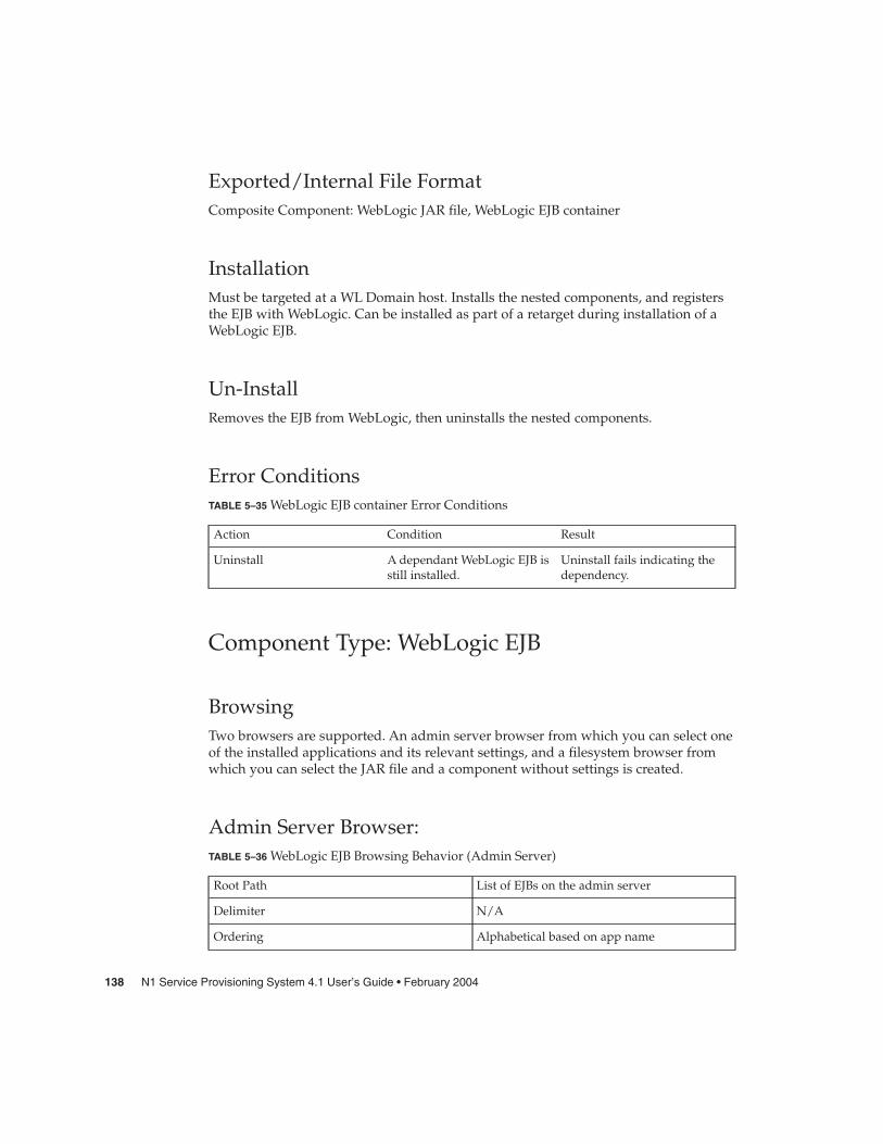
Exported/Internal File FormatComposite Component: WebLogic JAR file, WebLogic EJB container
InstallationMust be targeted at a WL Domain host. Installs the nested components, and registersthe EJB with WebLogic. Can be installed as part of a retarget during installation of aWebLogic EJB.
Un-InstallRemoves the EJB from WebLogic, then uninstalls the nested components.
Error ConditionsTABLE 5–35 WebLogic EJB container Error Conditions
Action Condition Result
Uninstall A dependant WebLogic EJB isstill installed.
Uninstall fails indicating thedependency.
Component Type: WebLogic EJB
BrowsingTwo browsers are supported. An admin server browser from which you can select oneof the installed applications and its relevant settings, and a filesystem browser fromwhich you can select the JAR file and a component without settings is created.
Admin Server Browser:TABLE 5–36 WebLogic EJB Browsing Behavior (Admin Server)
Root Path List of EJBs on the admin server
Delimiter N/A
Ordering Alphabetical based on app name
138 N1 Service Provisioning System 4.1 User’s Guide • February 2004

TABLE 5–36 WebLogic EJB Browsing Behavior (Admin Server) (Continued)Selection Type Single individual web app.
Only standalone EJBs will show up in this list.Any EJBs that are part of an EAR file will notbe displayed in, or selection allowed from, thislist.
Sample Path companyStoreEJBs
Filters None
Filesystem Browser:TABLE 5–37 WebLogic EJB Browsing Behavior (File System)
Root PathUses standard File Browser (directories arevalid selections)Delimiter
Ordering
Selection Type
Sample Path
Filters *.jar
Composite Component: WebLogic EJB Container
InstallationMust be targeted at a WL target (server/cluster) which will install the component onthat target, and install the contained reg component on the admin server of the target.
Un-InstallUntargets the EJB from the target, and if not currently targeted elsewhere, removes theregistration comp from the admin server.
Chapter 5 • Components 139

Error ConditionsTABLE 5–38 WebLogic EJB Container Error Conditions
Action Condition Result
Install The topology is incorrectlyconfigured (target hostdoesn’t point at correctdomain host)
Targeting fails.
Install The target host is not a validWL target.
Installation prohibited.
Browsing/Install/Uninstall Credentials aren’t properlyconfigured.
Operation fails.
Browsing Path not correctly configuredin domain host.
Browsing fails.
Component Type: WebLogic EAR file
BrowsingNot directly browsable. Must be obtained through WebLogic enterprise applicationbrowsers.
Exported/Internal File FormatThis component has a dual nature. It can be either a .EAR archive, or the explodedversion of that archive. Thus the file format is either an archive file in native format, ora package, respectively.
M-I DifferenceWill use the standard file/directory MI diff approach.
InstallationCan not be directly installed. Must be installed as part of a WebLogic enterpriseapplication container. The file/directory is copied to the filesystem based on the installpath, and then registered with the WL admin server.
140 N1 Service Provisioning System 4.1 User’s Guide • February 2004

Un-InstallCan not be directly uninstalled. The containing WebLogic EJB container must beuninstalled, which will result in the removal of this file/dir.
Error ConditionsSee Table 5–34
Component Type: WebLogic enterprise applicationsettings
BrowsingNot directly browsable. Must be obtained through WebLogic enterprise applicationbrowsers.
Exported/Internal File FormatOn export the relevant settings for this app will be read from the admin server andstored as a custom config gen’d file.
M-I DifferenceThe relevant settings for the Application will be exported into a file, which will becompared to the file that contained the settings during deployment.
InstallationCan not be directly installed. Must be installed as part of a WebLogic enterpriseapplication container. Installation involves reading the post-configured file andapplying all the settings to the admin server.
Un-InstallCan not be directly uninstalled. The containing WebLogic enterprise applicationcontainer must be uninstalled, which will result in the removal of this file and relatedsettings of the webapp within WebLogic. Settings not specific to the webapp will notbe removed.
Chapter 5 • Components 141

Error ConditionsSee Table 5–34
Component Type: WebLogic EnterpriseApplication Container
BrowsingNot directly browsable. Must be obtained through WebLogic enterprise applicationbrowsers.
Exported/Internal File FormatWebLogic EAR file, WebLogic enterprise application container, WebLogic List.
InstallationMust be targeted at a WL Domain host. Installs the nested components, and registersthe Enterprise Application with WebLogic. Can be installed as part of a retarget duringinstallation of a WebLogic enterprise application, or WebLogic Contained module.
Un-InstallRemoves the Enterprise Application from WebLogic, then uninstalls the nestedcomponents.
Error ConditionsTABLE 5–39 WebLogic Enterprise Application Container Error Conditions
Action Condition Result
Uninstall A dependant WebLogicenterprise application, orcontained WebLogic moduleis still installed.
Uninstall fails indicating thedependency.
142 N1 Service Provisioning System 4.1 User’s Guide • February 2004

Component Type: WebLogic EnterpriseApplication
BrowsingTwo browsers are supported. An admin server browser from which you can select oneof the installed applications and its relevant settings, and a filesystem browser fromwhich you can select the EAR file and a component without settings is created.
Admin Server Browser:TABLE 5–40 WebLogic Enterprise Application Browsing Behavior (Admin Server)
Root Path List of Enterprise Applications on the adminserver
Delimiter N/A
Ordering Alphabetical based on app name
Selection Type Single individual enterprise application.
Sample Path companyStoreAdmin
Filters None
Filesystem Browser:TABLE 5–41 WebLogic Enterprise Application Browsing Behavior (File System)
Root PathUses standard File Browser (directories arevalid selections)Delimiter
Ordering
Selection Type
Sample Path
Filters *.ear
Exported/Internal File FormatComposite Component: WebLogic enterprise application container.
Chapter 5 • Components 143

InstallationMust be targeted at a WL target (server/cluster) which will install the component onthat target, and install the contained reg component on the admin server of the target.
Un-InstallUntargets the enterprise app from the target, and if not targeted elsewhere, removesthe registration comp from the admin server.
Error ConditionsTABLE 5–42 WebLogic Enterprise Application Error Conditions
Action Condition Result
Install The topology is incorrectlyconfigured (target hostdoesn’t point at correctdomain host)
Targeting fails.
Install The target host is not a validWL target.
Installation prohibited.
Browsing/Install/Uninstall Credentials aren’t properlyconfigured.
Operation fails.
Browsing Path not correctly configuredin domain host.
Browsing fails.
Component Type: WebLogic List
BrowsingNot directly browsable. Must be obtained through WebLogic enterprise applicationbrowsers.
Exported/Internal File FormatThis component is a container component with some custominstall/uninstall/snapshot blocks. In all other ways it is only a generic containercomponent.
InstallationDoes not support direct installation.
144 N1 Service Provisioning System 4.1 User’s Guide • February 2004

Un-InstallDoes not support direct uninstallation.
Error ConditionsSee contained WebLogic module types.
Component Type: Contained WebLogic webApplication Container
BrowsingNot directly browsable. Must be obtained through WebLogic enterprise applicationbrowsers.
Exported/Internal File FormatComposite Component:
Contains a final WebLogic WAR file stub component, and a non-final, stub by default,WebLogic web application settings component.
Also contains a final compRef to the WebLogic enterprise application containercomponent contained by the WebLogic enterprise application that contains theWebLogic List that contains this component.
InstallationCan be installed on a WL Domain host. Results in the installation of the WebLogicenterprise application container as well.
Un-InstallUninstalls the WebLogic enterprise application container.
Chapter 5 • Components 145

Error ConditionsTABLE 5–43 Contained WebLogic web Application Container Error Conditions
Action Condition Result
Uninstall A dependant containedWebLogic web application isinstalled.
Uninstall fails indicating thedependency.
Component Type: contained WebLogic webapplicationSame as WebLogic web application except it contains a final Contained WebLogic webapplication container.
Component Type: Contained WebLogic EJBContainer
BrowsingNot directly browsable. Must be obtained through WebLogic enterprise applicationbrowsers.
Exported/Internal File FormatComposite Component:
Contains a final WebLogic JAR file stub component, and a non-final, stub by default,WebLogic web application settings component.
Also contains a final compRef to the WebLogic enterprise application containercomponent contained by the WebLogic enterprise application that contains theWebLogic List that contains this component.
InstallationCan be installed on a WL Domain host. Results in the installation of the WebLogicenterprise application container as well.
Un-InstallUninstalls the WebLogic enterprise application container.
146 N1 Service Provisioning System 4.1 User’s Guide • February 2004

Error ConditionsTABLE 5–44 Contained WebLogic EJB Container Error Conditions
Action Condition Result
Uninstall A dependant containedWebLogic web application.
Uninstall fails indicating thedependency.
Component Type: Contained WebLogic EJBSame as WebLogic EJB except it contains a final Contained WebLogic web applicationcontainer.
System ComponentsIn addition to the Component Types described above System Components alsoprovide functionality available to advanced plan and component authors. Thefollowing components have additional functionality:
Windows System ServiceThe Windows System Component provides utilities for interacting with differentwindows systems, beyond those related to any specific component type describedabove.
Control ProceduresTABLE 5–45 Contained WebLogic EJB Control Procedures (Windows)
Name Parameters Description
stopIIS None Shuts down the IIS process.
startIIS None Restarts IIS if it was notrunning
stopService serviceName: Name of theservice to stop.
Shuts down the service.
Chapter 5 • Components 147

TABLE 5–45 Contained WebLogic EJB Control Procedures (Windows) (Continued)startService serviceName: Name of the
service to start.Starts the windows service
WebLogic TargetThe WebLogic Target component provides utilities for interacting with WebLogicmanaged servers and clusters.
ProceduresTABLE 5–46 Contained WebLogic EJB Control Procedures (WebLogic)
Name Parameters Description
Start None Starts the target.
Stop None Stops the target.
Restart Boolean restart Restarts the target, based onthe value of the restart flag.
Component Type User InterfaceThe component types user interface provides the functionality for users to managecomponent types. Users can check-in component types, view lists of all componenttypes, view component type versions. Users can also view install information forcomponent types such as which hosts a component is installed on and which planinstalled the component.
The HTML User Interface also provides browsing of several component types. Thisallows for the selection of component types for remote check in.
The Component Type PageThe component type page allows you to list component types, view component typedetails, and create component types. This page also contains controls for filtering thecomponent type list and selecting sort criteria. You can change the sort criteria for thecomponent type list by clicking on one of the sort arrows in the header area. Clickeither the ascending or descending arrow selects that column for sorting and the sortorder.
148 N1 Service Provisioning System 4.1 User’s Guide • February 2004

Component Types A user definable text string that names the component object.By default, the components are listed in alphabetical orderby component name. You can sort the component type list byits name by clicking on one of the sort arrows in the headerarea for this column. Click either the ascending ordescending arrow selects this column for sorting and the sortorder.
Menu Group The component type menu is divided into several sections orgroups. This field identifies which section or group withinthe pull down menu the component type belongs. Note:Other than the hidden menu group, this field is only used as asort criteria and does not effect the menu list. Assigning acomponent type to the hidden menu group overrides themenu order causing the component type not to appear in themenu.
Menu Order This field controls where in the component type menu acomponent type name appears. The provisioning softwaresimply sorts the menu list in alpha numerical order based onthis field. You can use both number and letters in this field.However, the provisioning software has only used numbersby convention. To help organize the data the provisioningsoftware has also adopted the following numberingconvention.
Assigning a component type a menu group of Any WebLogicdoes not effect where in the menu the component type willappear. However, by following the arbitrary convention setby the provisioning software, assigning a component typethat belongs with the menu group of Any WebLogic the000100-xxxxxx-xxxxxx will put it in the menu in the correctplace.
Indent Level This defines how many units of 2 spaces to the right themenu item will be indented.
Description An optional user defined text string that describes thecomponent object. This attribute is not used by theprovisioning software application but can providemeaningful information to the user.
Defining Component Displays the component that defines this component type.
Version Displays the revision number of the component. Each time acomponent is modified, its version number is incremented.
Chapter 5 • Components 149

You can sort the component type list by version number byclicking on one of the sort arrows in the header area for thecolumn. Click either the ascending or descending arrowselects this column for sorting and the sort order.
Action Links that take you to other component type related pages toeither create a new component type, view more informationabout a specific component type, or edit component types.
The Component Type Details PageThe component types details page allows you to view Component types informationand attributes. None of the fields can be changed on this page.
Component Type Displays the name of the component type.
Menu Group Displays the name of the menu group.
Menu Order Displays 18 character code that controls where in the menuthis component type is placed.
Indent Level Displays how many spaces this menu item is indented.
Description Displays the description of the component type.
Defining Component Displays the component that defines this component type.
Version Displays the version number for this component type.
Edit Button A link that takes you to the component types edit page.
Done Button A link that takes you to the component types page.
The New Component Type Edit Page“Working with Components” on page 91 shows the Component Edit page whencreating a component. This edit page is different from the on used to edit existingcomponents.
Component Type Displays the name of the component type. This cannot bechanged.
Menu Group A text field that allows you to change the name of the menugroup for this component type. Only predefined menugroups are allowed.
Menu Order A text field that allows you to change the location in themenu for this component type. This field accepts any alphaor numeric character.
150 N1 Service Provisioning System 4.1 User’s Guide • February 2004

Indent Level A text field that allows you to change the indentation on themenu for this component type. This field accepts number inthe range of 0 through 10.
Description A text field that allows you to change the description for thiscomponent type.
Defining Component Displays the component that defines this componenttype.The View Component is a link that take you to thecomponent details page for the defining component.
Save Button Saves the contents of the edit page incrementing the versionnumber.
Cancel Button A link that takes you to the component types page.
� How To View Component Types
1. In the left-hand navigation menu, click administrative.
The HTML user interface displays the administrative page, which allows the userto select one of four administrative functions.
2. Click on the component types link on the administrative page.
The HTML user interface displays a list of the component types.
� How To View Component Types Details
1. In the left-hand navigation menu, click administrative.
The HTML user interface displays the administrative page, which allows the userto select one of four administrative functions.
2. Click on the component types link on the administrative page.
The HTML user interface displays a list of the component types.
3. Find the row listing the component type you’re interested in, and click details.
The HTML user interface displays a Components Types Details page for thecomponent type.
Steps
Steps
Chapter 5 • Components 151

� How To Create Component Types
1. In the left-hand navigation menu, click administrative.
The HTML user interface displays the administrative page, which allows the userto select one of four administrative functions.
2. Click on the component types link on the administrative page.
The HTML user interface displays a list of the component types.
3. In the top row of the table listing components types, enter a name in thecomponent types field for the new component type, and click create.
The HTML user interface displays the Components Types Details Edit page for thenew component type.
4. Use the controls on this page to specify the necessary information that will makeup the component type.
a. Change the name in the component field, if desired. Once the component ischecked in you will not be able to change the name.
b. Enter a Menu Group name.
c. Define the menu order by entering a 18 digit number.
d. Specify the indent level.
e. Enter a description in the Description field.
f. Enter a description if one is desired.
g. Select a defining component.
h. When finished click save.
� How To Edit Component Types
1. In the left-hand navigation menu, click administrative.
The HTML user interface displays the administrative page, which allows the userto select one of four administrative functions.
2. Click on the component types link on the administrative page.
The HTML user interface displays a list of the component types.
3. Find the row listing the component type you’re interested in, and click details.
Steps
Steps
152 N1 Service Provisioning System 4.1 User’s Guide • February 2004

The HTML user interface displays a Components Types Details page for thecomponent type.
4. Click the edit button located near the bottom of the page.
The HTML user interface displays a Components Types Details Edit page for thecomponent type.
5. Use the controls on this page to change any information that you want to change.
� Enter a Menu Group name.� Define the menu order by entering a 18 digit number.� Specify the indent level.� Enter a description in the Description field.� Enter a description if one is desired.� Select a defining component.� When finished click save.
General Purpose Extended ControlServicesExtended control services are procedures that perform a software operation related toa resource or component. These services include services for starting and stop theMicrosoft IIS Web Server and for starting and stopping specific Windows services. Theprovisioning software includes two sets of extended control services that are notspecific to individual resource types:
� general purpose control services, which can be called by any component or plan
� resource-type-specific control services, which are related to a specific type ofresource and that can be called only by components or plans that include resourceswith those resource types
General purpose control services include the ability to start or stop Windows services.These control services can be called by any component or plan.
An example of a resource-type-specific control service is the startRouter procedureincluded with the COM+ Application resource type. This procedure starts COM+routing services. It works only with resources that are of the COM+ Applicationresource type.
Chapter 5 • Components 153

Extended Control Services for IISTable 5–47 lists the provisioning software’s built-in procedures for controlling IIS.
TABLE 5–47 Built-in Procedures for Controlling IIS
Name Parameters Description
stopIIS None Shuts down the IIS process.
startIIS None Restarts IIS if it is not running
Extended Control Services for Windows ServicesA component or plan may include steps to start or stop specific Windows Services.
Table 5–48 describes provisioning software’s built-in procedures for controllingWindows Services.
TABLE 5–48 Built-in Procedures for Controlling Windows Services
Name Parameters Description
stopService serviceName: Name of theservice to stop.
Shuts down the service.
startService serviceName: Name of theservice to start.
Starts the windows service
154 N1 Service Provisioning System 4.1 User’s Guide • February 2004

CHAPTER 6
Plans
A plan is an XML document that performs operations on hosts specified by theoperator.
This section discusses the following topics:
� “Working with Plans” on page 155� “Running Plans” on page 166
Working with PlansA plan is a sequence of instructions typically used to manipulate one or morecomponents. For example, an execution plan may instruct the provisioning software toinstall three components and initiate the “startup” control on another. A plan can alsobe defined as a sequence of other plans, which allows common instruction sequencesto be shared between multiple plans.
The provisioning software provides an in-memory representation of the objectsexpressed by the plan and component language and also defines a process for thevalidation, persistence and version control for those objects. The provisioning softwaremanages the physical resources associated with a component. When the provisioningsoftware executes a plan, substitution variables declared by a component are replaced.The Notification feature can be used to send email in response to plan executionrelated events. The provisioning software also includes a number of predefinedcomponents that may be used directly, or as samples for constructing othercomponents.
155

Plan TypesWithin the N1 Service Provisioning System software mode there are two types ofplans:
� Composite plans, which contain only subplans.� Simple plans, which contain a collection of simple steps, but which cannot call
other plans.
The XML Schema enforces these restrictions so that you can either have a top-levelplan which only calls other subplans, or you can have a simple plan with varioussimple steps but no calls to other subplans. The distinction is important because thesteps contained in a simple plan all execute on the same set of target hosts, whereasthe steps of a composite plan may execute on different sets of target hosts, using oneset of target hosts for each simple plan recursively contained in the composite plan.
Types of StepsSteps are logical blocks that manage what to do with subplans or components. The N1Service Provisioning System software supports three types of steps:
� Steps that can be called only from a component. These steps can in turn be dividedinto two types:
� Component steps that can only be called from an install block.� Component steps that can be called from outside an install block.
� Steps that can be called only from plans. These steps consist of two groups:
� Steps that can be called only from composite plans.� Steps that can be called only from simple plans.
� Steps that can be called from both components and plans
Plan XML SchemaFor a detailed description of the XML schema for plans, see N1 Service ProvisioningSystem 4.1 Reference Guide.
Plans User Interface
The Plans PageThe plans page allows you to list plans, view plan details, create plans, and edit plans.This page also contains controls for filtering the component list and selecting sortcriteria. There are blue wedge shaped arrows over several of the columns on the planspage that allow you to select the column to sort the list by and in either ascending or
156 N1 Service Provisioning System 4.1 User’s Guide • February 2004

descending order. When one of the arrows is clicked it selects that column by which tosort, sorts the list in either ascending or descending order (depending on which arrowwas clicked), and changes the arrow to white . The white arrow indicates whichcolumn was used for the sort and in which order (ascending or descending).
Path Allows you to specify where to look for or store plans. Click on changepath to specify a different path.
Show Allows you to list either plans or components. If you selectcomponents, the HTML user interface displays the components pageas though you had click on the components option in the left-handnavigation menu.
You can also narrow the list by selecting a category from the categorypull down menu.
(Check Box) Marks a plan for inclusion when one of the actions are clicked in theActions for Checked plans area. When clicked, Actions for Checked planswill either delete or categorize a plan.
Plan A user definable text string that names the plan object. By default, theplans are listed in alphabetical order by plan name. You can changethe sort order between ascending and descending by clicking on oneof the sort icons that is in the plans header area.
Version Displays the revision number of the plan. Each time aplan is modified, its version number is incremented.
You can sort the plan list by version number by clickingon one of the sort icons in the header area for thiscolumn. Clicking this icon toggles the order betweenascending and descending.
Description An optional user defined text string that describes theplan object. This attribute is not used by theprovisioning software but can provide meaningfulinformation to the user.
Action Links that take you to other plan related pages to eitherfind a specific plan, create a new plan, view moreinformation about a plan, or view the run history for aplan.
Actions for Checked Plans From this area you can either delete or apply categoriesto the checked plan(s).
Chapter 6 • Plans 157

The Plans Details PageThe Plans Details page allows you to view a Plan’s information and attributes. Thispage includes information and attributes information, and also contains buttons thatallow you to run, edit, and delete a plan.
Plan The name of the plan.
Version Displays the revision number of the plan.
Checked In Displays the date and time when the plan was checked in. That is,created or modified.
Checked In By Displays the user ID of the one who checked in the plan. Thisprovides an audit trail when trying to troubleshoot problems orinconsistencies.
Category A user definable object that is used to filter the plan list. Categoriesare created using the categories page accessed from theAdministrative page. Categories are then applied to a plan from theplans page. Categories can also be created by clicking in the “ApplyCategories . . .” link.
Description An optional user defined text string that describes the plan object.This attribute is not used by the provisioning software but canprovide meaningful information to the user.
Buttons By clicking one of these buttons you initiate one of the followingfunctions.
Run Runs the plan.
Advanced Edit Allows you to edit the XML code for the plan.
Delete Removes the plan from the database. If there ismore than one version then the provisioningsoftware asks if you want to delete just thisversion or all versions.
Done Takes you to the plans page.
Download Allows you to save the XML code to a text file.Between this function and the Replace DefinitionWith File function the provisioning softwareallows you to use other text editors to create andmodify the XML code for plans.
The Plans Advanced Edit PageThe Plan Advanced Edit page allows you to change what a plan does by changing theXML code of a plan.
158 N1 Service Provisioning System 4.1 User’s Guide • February 2004

Plan Allows you to change the name of the plan.
Version Displays the revision number of the plan. This willincrement when the plan is checked in. This cannotbe changed by the user.
Checked In This will reflect a new time and date when the plan ischecked in. This cannot be changed by the user.
Checked In By This will reflect the user ID of the one who checks inthe plan providing an audit trail. This cannot bechanged by the user.
Category Displays the category for the plan. Categories can beassigned or changed at from the plans page byclicking in the “Apply Categories . . .” link.
Edit The Plan Definition This is a text field that displays the XML codedefining what the plan does. You can make anydesired changes directly into this text field.
Replace Definition With File: This is a text field that allows you to replace the XMLcode in the plan definition field with that of a textfile. Either type in the name of the file, including thepath, into the text field or use the browse button tolocate a file. Initiate this feature by clicking on theReplace link just to the right of the browse button.
Buttons By clicking one of these buttons you initiate one ofthe following functions.
Check in Allows you to check in the plan usingits current name.
Check in as Allows you to check in the plan usinga new name.
Cancel Takes you to the plans page withoutsaving any changes.
� How To View Plans List
� In the left-hand navigation menu, click plans.
The HTML user interface displays the plans page, which lists the plans alreadychecked in to the database. By clicking on one of the sort arrows in the header yocan change the sort criteria.
Steps
Chapter 6 • Plans 159

� How To View Plan Details
1. In the left-hand navigation menu, click plans.
The HTML user interface displays the plans page, which lists the plans alreadychecked in to the database.
2. Find the row listing the plan you’re interested in, and click details.
The HTML user interface displays a Plan Details page for the plan.
� How To Edit Plans
1. In the left-hand navigation menu, click components.
The HTML user interface displays the plans page, which lists the plans alreadychecked in to the database.
2. Find the row listing the plan you’re interested in, and click details.
The HTML user interface displays a Plan Details page for the plan.
3. Click the advanced edit button.
The HTML user interface displays a Plan Advanced Edit page for the plan.
4. In the text box, make the changes you want to the plan’s XML code, or enter newXML for the plan that you have authored in another program.
To upload a plan stored on your local system, enter the path of the file or use thebrowse button, then click Replace.
5. Click the check in button to use the same name or click the check in as button touse a different name.
The HTML user interface displays the plans page, which lists the plans alreadychecked in to the database.
The HTML user interface displays a new page, telling you that you are about tocheck in a plan and increments the version number.
6. Click continue to check in to finish checking in the plan.
How To Create PlansYou can create an auto-generated plan, create a completely custom plan, or start withan auto-generated plan and customize it.
Steps
Steps
160 N1 Service Provisioning System 4.1 User’s Guide • February 2004

The N1 Service Provisioning System software can automatically generate a planconsisting of multiple “direct run” procedures. You can run this plan directly or save itfor use as a template for more sophisticated plans that you author in XML.
For deployments that involve the coordination of multiple components, multiple hostsets, or both, write a plan and use the provisioning software XML schema to defineoperations such as dependency checks and scripting that executes commands on anapplication console. Once the plan is written, you need to check it into the planrepository.
� How To Create Auto Generated Plans
1. In the left-hand navigation menu, click components.
The HTML user interface displays the components page, which lists thecomponents already checked in to the database.
2. In the table listing components, find the row describing the component youwould like to deploy, and click details.
The HTML user interface displays a Components Details page for the component.
3. In the component procedures table, click the checkbox next to the name of eachprocedure you want to include in the plan.
4. When you have selected all the procedures you want to include, click the linklabeled generate plan with checked procedures.
The HTML user interface displays a Plan Advanced Edit page for the plan.
5. Click check in.
� How To Create Custom PlansYou can begin by writing the XML code for the plan using a schema-validating editorsuch as TurboXML or you can write the XML code within the HTML user interface.The following description assumes that you will write the XML code using an externaleditor.
1. Using a schema-validating editor, write your plan using the XML schemaelements described in N1 Service Provisioning System 4.1 Reference Guide.
2. When you have finished writing the plan, log in through your web browser.
3. In the left-hand navigation menu, click plans located under the applicationdeployment heading.
Steps
Steps
Chapter 6 • Plans 161

The HTML user interface displays the plans page, which lists the plans alreadychecked in to the database.
4. In the top row of the table listing plans, enter a name and a brief description forthe plan you want to create, and click create.
The HTML user interface displays a Plan Advanced Edit page for the plan . Notethat the provisioning software has populated the plan definition with an XMLskeleton.
In the text box, enter the XML for the plan. To upload a plan stored on your localsystem, enter the path of the file or use the browse button, then click Replace.
5. Click the check in button.
The HTML user interface displays a new page, telling you that you are about tocheck in a plan. It assigns the plan version 1.0.
6. Click continue to check in to finish checking in the plan.
Summary of CLI CommandsTable 6–1 lists the CLI commands you can use to manage plans.
TABLE 6–1 Summary of the pdb Commands
Command Description
pdb.p.ci Checks in a new version of a plan.
pdb.p.co Checks out a plan (outputs a plan in XML).
pdb.p.genplan Generates and outputs a plan in XML.
pdb.p.la Lists the latest versions of all plans.
pdb.p.lo Views a plan.
pdb.p.lv Lists all the versions of the specified plan.
pdb.p.del Deletes an execution plan.
pdb.p.sh Shows or hides a plan.
pdb.p.sc Associates a plan with a set of categories.
Note – To run plans, use the pe commands described in Table 6–2.
162 N1 Service Provisioning System 4.1 User’s Guide • February 2004

Session VariablesSession variables are global values associated with deployments that expands theflexibility of the provisioning software. Session variables can be created and saved forfuture use with any deployment or created and not saved for use with a singledeployment.
Session Variables User Interface
The Session Variables PageThe Session Variables page allows you to list, create, edit and, view the details ofSessions Variables.
(Check Box) Marks a session variable for inclusion when one of theactions are clicked in the Actions for Checked SessionVariables area. When clicked, Actions for Checked SessionVariables will either delete the session variable.
Session Variable A user definable text string that names the sessionvariable object.
Password Indicates if a password is required to change the sessionvariable.
Value Displays the value of the session variable. If a passwordis required for the session variable the value is seen as aseries of ellipses
Action Links that take you to other session variables relatedpages to either create or edit a session variable.
Actions for Checked Plans From this area you can delete the checked sessionvariable(s).
The Session Variables Details PageThis page is used to view the details for a session variables.
Session Variable Displays the name of the session variable object.
Description An optional user defined text string that describes the sessionvariable. This attribute is not used by the provisioning softwarebut can provide meaningful information to the user.
Chapter 6 • Plans 163

Value Displays the value of the session variable unless it is passwordprotected.
Session Variables Displays the name of the session variable object.
Buttons By clicking one of these buttons you initiate one of the followingfunctions.
Delete Allows you to permanently delete the sessionvariable.
Edit Takes you to the edit page for the session variable.
Done Takes you to the session variables page withoutsaving any changes.
The Session Variables Edit PageThis page is used to create and edit session variables. If you are editing an existingsession variable the top two items are displayed and cannot be changed.
Session Variable A text field that allows you to enter a name for the sessionvariable. If this is an existing session variable then this field onlydisplays the name. It cannot be changed.
(Check Box) Marks this session variable as password protected. Whenchecked, the value of the session variable will be seen as a seriesof ellipses.
Description A text field that allows you to enter an optional text string thatdescribes the session variable. This attribute is not used by theprovisioning software but can provide meaningful information tothe user.
Value A text field that allows you to enter a value of the sessionvariable.
Password A text field that allows you to enter a password for the sessionvariable.
Buttons By clicking one of these buttons you initiate one of the followingfunctions.
Save Saves the changes and takes you to the sessionvariables page.
Cancel Takes you to the session variables page withoutsaving any changes.
164 N1 Service Provisioning System 4.1 User’s Guide • February 2004

� How To View Session Variables
� In the left-hand navigation menu, click session variables.
The HTML user interface displays the session variables page, which lists thesession variables already checked in to the database.
� How To View Session Variables Details
1. In the left-hand navigation menu, click session variables.
The HTML user interface displays the session variables page, which lists thesession variables already checked in to the database.
2. Find the row listing the session variable you’re interested in, and click details.
The HTML user interface displays a session variables Details page for the sessionvariable.
3. Near the bottom of the page, click the done button when finished.
The HTML user interface displays a session variables page.
� How To Edit Session Variables
1. In the left-hand navigation menu, click session variables.
The HTML user interface displays the session variables page, which lists thesession variables already checked in to the database.
2. Find the row listing the session variable you’re interested in, and click details.
The HTML user interface displays a session variables Details page for the sessionvariable.
3. Near the bottom of the page, click the edit button.
The HTML user interface displays the session variables edit page for the sessionvariables.
4. Using the text fields make any desired changes.
5. Near the bottom of the page, click the save button when finished.
The HTML user interface save the changes and displays a session variables page.
6. Near the bottom of the page, click the cancel button to cancel any changes.
Steps
Steps
Steps
Chapter 6 • Plans 165

The HTML user interface displays a session variables page without saving anychanges.
Running PlansOnce you have checked in a plan, you can run it in order to perform operations onhosts.
� How To View Running Plans
1. In the left-hand navigation menu, click plans.
The HTML user interface displays the plans page, which lists the plans alreadychecked in to the database.
2. Find the row listing the plan you’re interested in, and click details.
The HTML user interface displays a Plan Details page for the plan.
3. Near the bottom of the page, click the run button.
The HTML user interface displays a Plan Details Run page.
4. Enter the required information and click run preflight only to verify that the planwill run successfully or click run plan (includes preflight) to run the plan.
� How To Use a Component’s Direct Run ProceduresFor straightforward deployments that don’t involve multiple components orsynchronization among hosts, you may not need to write a plan at all. Instead, youmay be able to use one of the “direct run” procedures that the provisioning softwareautomatically generated when you checked in the component you want to deploy.
To use one of these “direct run” procedures, do the following:
1. In the left-hand navigation menu, click components.
The HTML user interface displays the components page, which lists thecomponents already checked in to the database.
Steps
Steps
166 N1 Service Provisioning System 4.1 User’s Guide • February 2004

2. In the table listing components, find the row describing the component youwould like to deploy, and click details.
The HTML user interface displays a Components Details page for the component.
3. In the component procedures table, click the checkbox next to the name of theprocedure you want to run, and then click run.
The HTML user interface displays the Plan Details Run page for the procedure.
4. Use the fields on the page to enter the variables and select the parameters youwant to use when you run the plan.
� In the plan parameters area, use the target host field to select the host on whichyou want to run this plan, or use the pull-down menu to select a target host set.
� In the plan variables area, configure the variables you want to set. Whetherthere are variables to configure depends on the contents of the plan.
� In the options area, select whether you want to perform a detailed preflight.Running a detailed preflight increases the amount of time preflight takes, butalso increases the detail the preflight goes into.
� In the limits area, limit the number of hosts running at the same time byentering the number of hosts in the field provided. You can also limit overallrunning time of plan or limit running time of native calls by entering a numberin the fields provided, and then selecting the time unit, such as “minutes,” frompull-down menus.
5. Do one of the following:
� To run just the preflight test of the procedure, click run preflight only.
� To run the preflight test and then (assuming the preflight test finds no errors)to run the procedure itself, click run plan (includes preflight).
Summary of CLI CommandsTable 6–2 describes the CLI commands associated with running plans.
TABLE 6–2 Summary of the pe Commands
Command Description
pe.h.prep Prepares a set of hosts.
pe.p.en Displays the output of an execNative step.
pe.p.la Lists running and completed plans.
pe.p.lo Lists information about a running orcompleted plan.
Chapter 6 • Plans 167

TABLE 6–2 Summary of the pe Commands (Continued)Command Description
pe.p.del Deletes the history of a completed plan run.
pe.p.lp Lists the subplans and targets associated witha plan.
pe.p.run Runs a plan.
pe.p.stop Stops a plan that is running
pe.pi.lo Lists the parameters used to run a plan.
168 N1 Service Provisioning System 4.1 User’s Guide • February 2004

CHAPTER 7
Comparisons
Comparisons are used to validate an installation or system configuration. Bycomparing the configuration of a host against its original configuration you can tell ifanything has changed. You can also compare one or more hosts against a referencehost to ensure that all hosts are configured the same. With the N1 Service ProvisioningSystem software you can compare one or more hosts against another host, one or morehosts against a model in the Master Server, or a host against its original configuration.The provisioning software allows you to check the entire configuration of a host orlimit what is checked to a single directory.
When you have run a comparison, you can save the output to a file and view it in astandard application such as Excel.
This section discusses the following topics:
� “Snapshots” on page 169� “Types of Comparisons and Their Features” on page 170� “Running Comparisons” on page 173
SnapshotsSnapshots are an advanced feature that define what a component should capture atthe time it is installed and when it is analyzed for differences. Snapshots are largely achange management tool that helps in the process of detecting when a componentinstallation has changed.
Because the source items for a component is deployed in the order in which they arelisted in the component’s XML file, it’s possible for one source item to overwriteanother that has already been deployed, if they both have the same name.
169

How Snapshots HelpOne way that a snapshot is used is to validate that a deployment was done correctly.Because the source items for a component is deployed in the order in which they arelisted in the component’s XML file, it’s possible for one source item to overwriteanother that has already been deployed, if they both have the same name.
For example, you may have a component that installs the source for a componentnamed pockets onto a host. One source (S1) of the pants component, pants/config.txtmay be deployed, followed by a second, different source (S2), also pants/config.txt. Ifyou were then to go and look at pants/config.txt you might think you were looking atS1, when in fact, config.txt now reflects the contents of S2. To avoid this sort ofdifficulty, you can define a snapshot that the provisioning software can use to makesure the correct baseline, post installation version of config.txt is used in anyModel-to-install comparisons.
Another way snapshots are useful is when a component’s source items might betransformed using the transform element, or otherwise changed during the course ofdeployment by an execNative call that you have defined. Without a snapshot of the“just installed” state, a Model-to-Install comparison would be made against the sourceitems before they were deployed, which would lead to errors in the results.
It is not necessary to define a snapshot block, or specify that one be used, in yourcomponents. However, if one is not specified, the installed component that you arecomparing against the model will contain no snapshot information, and will neverpresent any differences.
Types of Comparisons and TheirFeaturesN1 Service Provisioning System software allows you to perform three types ofcomparisons:
� Model to Model (M-M)� Model to Install (M-I)� Install to Install (I-I)
Model to Model ComparisonsA Model to Model comparison is the simplest type of comparison. It compares the listof components that the provisioning software has installed on one host with the list ofcomponents that the provisioning software has installed on another host. This is
170 N1 Service Provisioning System 4.1 User’s Guide • February 2004

purely a comparison of the records that the provisioning software has about what ithas installed. If there have been out of band changes made to either component list,they will not be detected. A Model-to-Model comparison takes place entirely on theMaster Server based on information it has received about what has been deployed.
Model-to-Install ComparisonsA Model-to-Install comparison compares the ‘just installed’ state of the resources in acomponent or components to their current state on a given host or host set. You canspecify that this comparison compares the model to hosts, host sets, or to componentlevel.
A Model-to-Install comparison uses information about what components andsubsequent resources have been deployed to a given host based on snapshotinformation. A snapshot is a record of the state of an installed component immediatelyafter it has been deployed to a host. The component’s XML model includes parametersthat control the scope of this snapshot. For example, the XML model can list files, suchas log files, that should be ignored during a comparison.
When the provisioning software performs a Model-to-Install comparison, the MasterServer looks up the list of snapshots for all the components being compared. It sendsthis list to the Remote Agent on the host where the components are installed. Thesnapshot information includes rules for any files and directories that should beignored during the comparison. The Remote Agent then processes these rules. BothMaster Server and Remote Agents must be using the same locale for theModel-to-Install comparison to function properly.
Unlike Model-to-Model comparisons, which compare one ideal installation to another,Model-to-Install comparisons compare the actual state of the installed component orcomponents at deployment time against their current state.
Install-to-Install ComparisonsInstall-to-Install comparisons compare the current states of the contents of directoriesin components that the provisioning software has installed on two different hosts. Thelist of elements (files, directories, and so on) from the reference host being compared inan Install-to-Install comparison are grouped into batches on the Master Server andthen sent to the Remote Agent of the comparison host for processing. If you havedefined some rules about file types or specific directories or files for the provisioningsoftware to ignore, the Master Server will discard the appropriate items before sendingthe remainder of the list to the comparison host. The Remote Agents from each hostmust be set to use the same locale for Install-to-Install comparisons to functionproperly.
Chapter 7 • Comparisons 171

You can provide the provisioning software with scripts to be run before and after thecomparison occurs, in case you need to manipulate files before running thecomparison or need to clean up any files you have manipulated to prepare for thecomparison.
Why Use Scripts in Install-to-Install Comparisons?If the components you are comparing include resources that stored in a package, adatabase, or an archive such as a ZIP file, you can use scripts to export or transformthe resources before the comparison occurs. Use execNative step to direct theprovisioning software to perform native commands such as unzipping or exportingfile contents.
Using Scripts in Install-to-Install ComparisonsYou can run any native command within the prepare and cleanup blocks. A commonusage of these blocks before and after a comparison is to extract the files from acompressed archive and output them to a specified output file, then delete that fileduring the cleanup.
Note – Unlike the execNative contained in a plan or component, this execNativeinstance must be contained within either a <prepare> or a <cleanup> block, andcannot make use of any variable substitutions.
When you are performing an Install-to-Install comparison using the HTML userinterface, you can select a checkbox labeled include temporary files generated byscripts during comparison. When you select this option, the page refreshes andprovides two fields into which you can enter the prepare and cleanup blocks.
You can also specify alternate prepare/generate and cleanup blocks for the target hostby un-selecting the appropriate boxes.
You can enter scripts such as these into the fields:
This prepare /generate block specifies the output file for the result of theexecNative. The execNative lists the contents of the /tmp directory.
<prepare><execNative outputFile="file.txt" dir="temp"><exec cmd="ls"><arg value="-l"></arg><arg value="/tmp"></arg>
</exec>
</execNative></prepare>
172 N1 Service Provisioning System 4.1 User’s Guide • February 2004

This cleanup block then removes the outputFile, file.txt, from the temp directory.
<cleanup><execNative dir="/temp/"><exec cmd="rm"><arg value="-rf"></arg><arg value="file.txt"></arg>
</exec>
</execNative></cleanup>
Running Comparisons
Time Synchronization for ComparisonsBecause the time stamp for a comparison is based on the clock in the Master Server, itis a good idea to run some kind of synchronization utility on all your N1 ServiceProvisioning System software machines so that all system clocks are synchronized onthe same time.
M-I (Model to Installation) ComparisonsAn M-I comparison (sometimes called an M-I difference) is a comparison of acomponent model to a specific installation of a component. When relevant, thischapter’s description of a resource type will include information about how the formator content of a resource type affects an M-I comparison.
During a snapshot the current state of the metabase is exported into an XML file.During an M-I comparison, the metabase is re-exported and compared against theoriginal XML file.
M-I Comparison for IIS Types IntroductionDuring a snapshot the current state of the metabase is exported into an XML file.During an M-I difference the metabase is re-exported and compared against theoriginal XML file. The standard XML differentiator is used to generate differencesbetween these files.
Chapter 7 • Comparisons 173

M-I Comparison for COM+ ApplicationThe COM+ Application is re-exported on the target system as an MSI file andcompared against the MSI file used to install the application. M-I difference will onlyindicate that there were differences (i.e. the two binary files are different) but will notindicate the details of the differences.
M-I Comparison for COM ComponentThe COM component is compared as a binary file against the file used duringinstallation. M-I difference will only indicate that there were differences (i.e. the twobinary files are different) but will not indicate the details of the differences.
M-I Comparison for H KeysDuring a snapshot the current state of registry key (and its children) is exported intoan XML file. During an M-I difference the registry key is re-exported and comparedagainst the original XML file. The standard XML differentiator is used to generatedifferences between these files.
M-I Comparison for Registry SettingsM-I Differencing is not supported for *.reg files. Snapshots will not be taking duringinstallation resulting in nothing to difference during the M-I difference. If the userwould like to difference registry changes they are encouraged to use the built-inRegistry keys type.
M-I Comparison for MSI Files or Windows Installer FilesM-I Differencing is not supported for Windows Installer files. Snapshots will not betaking during installation resulting in nothing to difference during the M-I difference.Since ROX does not have first-hand knowledge of the actions taken during theinstaller run it is not feasible to determine what needs to be captured.
M-I Comparison for Windows Batch FilesM-I Differencing is not supported for Windows Batch files. Snapshots are not takenduring installation resulting in nothing to difference during the M-I difference.
M-I Comparison for Comparison for Windows ScriptingHost FilesM-I Differencing is not supported for WSH files. Snapshots will not be taking duringinstallation resulting in nothing to difference during the M-I diff.
174 N1 Service Provisioning System 4.1 User’s Guide • February 2004

M-I Comparison for WebLogic WAR FilesWill use the standard file/directory MI difference approach.
M-I Comparison for WebLogic Web Application SettingsThe relevant settings for the application will be exported into a file, which will becompared to the file that contained the settings during deployment.
M-I Comparison for WebLogic JAR FilesWill use the standard file/directory MI difference approach.
M-I Comparison for WebLogic EJB SettingsThe relevant settings for the EJB will be exported into a file, which will be compared tothe file that contained the settings during deployment.
M-I Comparison for WebLogic EAR FilesWill use the standard file/directory MI difference approach.
M-I Comparison for WebLogic Enterprise ApplicationSettingsThe relevant settings for the Application will be exported into a file, which will becompared to the file that contained the settings during deployment.
Comparisons User Interface
The Comparisons PageThe Comparisons user interface provides the functionality for users to create, run, andview the results of comparisons.
This page also contains controls for filtering the component list and selecting sortcriteria. There are blue wedge shaped arrows over the comparison column that allowyou to sort the list by and in either ascending or descending order.
Chapter 7 • Comparisons 175

Comparison A user definable text string that names the comparisonobject. By default, the comparisons are listed inalphabetical order by component name. You can changethe sort order between ascending and descending byclicking on one of the sort icons that is in the plansheader area.
Description An optional user defined text string that describes thecomparison object. This attribute is not used by theprovisioning software but can provide meaningfulinformation to the user.
Action Links that take you to other comparison related pagesto either create, view details for, or view the results ofcomparisons.
Actions for Checked Plans From this area you can either delete or apply categoriesto the checked plan(s)
The Comparisons Details PageThe details page for comparisons is different for each of the three types ofcomparisons.
The Comparisons Details Page for M to MComparison Displays the names the comparison object.
Category A user definable object that is used to filter the comparisonslist. Categories are created using the categories page accessedfrom the Administrative page. Categories are then applied toa plan from the plans page. Categories can also be created byclicking in the “Apply Categories . . .” link.
Description An optional user defined text string that describes thecomparison object. This attribute is not used by theprovisioning software but can provide meaningfulinformation to the user.
Style of Comparison This allows you to select the type of comparison you want.
Model to Model Sets up the user interface to run a modelto model comparison.
Model to Install Sets up the user interface to run a modelto install comparison.
Install to Install Sets up the user interface to run an installto install comparison.
176 N1 Service Provisioning System 4.1 User’s Guide • February 2004

Reference Host Specifies which hosts model to use as a reference model forthe comparison.
Comparison Host Specifies which hosts model to compare to the referencehost’s model.
Limits This allows you to set a time limit for the provisioningsoftware to complete the comparison. Some types of problemscan cause the provisioning software to wait endlessly whileattempting to take a snapshot of an installation. This featureprovides a time-out to prevent the provisioning softwarefrom never finishing a comparison.
Buttons By clicking one of these buttons you initiate one of thefollowing functions.
Save Saves the comparison using the currentname.
Save As Saves the comparison using a differentname.
Save & Run Saves the comparison using the currentname and performs a comparison.
Previous Results Displays previous results of acomparison.
Delete Deletes the comparison.
Cancel Takes you to the comparisons pagewithout saving any changes.
The Comparisons Details Page for M to IThis comparison allows you to validate that current state of an installation bycomparing it to its last know good state.
Because only the model reference and comparison object area changes, the followingdiscussion will focus only on the area of the comparisons page that is different.
Scope This is a pull down menu that allows you to limit the scope of thecomparison to either a host set, a host, or component.
Host Set - changes the following field on this page to allow you to select which hostset to compare. The provisioning software then compares that last known state of thespecified host set to its current state.
Host - changes the following field on this page to allow you to enter a host name tocompare. The provisioning software then compares that last known state of thespecified host to its current state.
Chapter 7 • Comparisons 177

Component - changes the following field on this page to allow you to enter a hostname and component path to compare. The provisioning software then compares thatlast known state of the specified component to its current state.
Directories & Files to Ignore During ComparisonAllows you to specify things to ignore during this comparison. This feature allowsthe provisioning software to accommodate changes to things like log files withoutcausing the comparison to fail.
The Comparisons Details Page for I to IThis comparison allows you to validate that current state of an installation bycomparing it to an other know good installation.
Because only the model reference and comparison object area changes, the followingdiscussion will focus only on the area of the comparisons page that is different.
Reference Host Specifies which hosts to use as a reference model for thecomparison. This also includes a second field that requires thatyou specify where in the hierarchical files structure to limit thecomparison. If you use the top of the tree structure you willevaluate the entire host.
Comparison Host Specifies which hosts to compare to the reference host’s model.This also includes a second field that requires that you specifywhere in the hierarchical files structure to limit the comparison.
OptionsDefines some parameters when taking a snapshot of the host.
Include All Sub-Directories in Comparison — This causes the provisioning softwareto recursively follow all subdirectories. within a parent directory.
Follow Symbolic Links Found in Directories — This causes the provisioningsoftware to resolve symbolic links to determine that what the link points to is alsovalid.
Include Temporary Files Generated by Scripts During Comparison — This causesthe provisioning software to include any legacy files generated by running a script.This can be used to verify that a particular script has or has not been run on all thehosts included in the comparison.
Directories & Files to Ignore During ComparisonAllows you to specify things to ignore during this comparison. This feature allowsthe provisioning software to accommodate changes to things like log files withoutcausing the comparison to fail.
178 N1 Service Provisioning System 4.1 User’s Guide • February 2004

� How To View Comparisons List
� In the left-hand navigation menu, click comparisons.
The HTML user interface displays the comparisons page, which lists thecomparisons already checked in to the database. By clicking on one of the sortarrows in the header yo can change the sort criteria.
� How To View Comparisons Details
1. In the left-hand navigation menu, click comparisons.
The HTML user interface displays the comparisons page, which lists thecomparisons already checked in to the database.
2. Find the row listing the plan you’re interested in, and click details.
The HTML user interface displays the comparisons Details page for thecomparison.
� How To Create an M to M Comparison
1. In the left-hand navigation menu, click comparisons.
The HTML user interface displays the comparisons page, which lists thecomparisons already checked in to the database.
2. Find the row listing the plan you’re interested in, and click details.
The HTML user interface displays the comparisons Details page for thecomparison.On this page you select the type of comparison you want to define, and you defineparameters for the comparison. When the page is first displayed, it is configuredfor a Model-to-Model comparison.
3. In the style of comparison area, leave model to model selected.
4. In the reference host field, enter the name of the host whose model should serveas the reference (the standard) for the comparison. If you like, you can clickselect from list to perform a host search to find the host.
5. In the comparison host field, enter the name of the host whose model you wouldlike to compare to the reference model. If you like, you can click select from listto perform a host search to find the host.
6. In the fields labeled limits, specify the maximum number of hours or minutesthe comparison should run. By default, comparisons are allowed to run for 4
Steps
Steps
Steps
Chapter 7 • Comparisons 179

hours.
7. Click save to save the comparison.
� How To Create an M to I Comparison
1. In the left-hand navigation menu, click comparisons.
The HTML user interface displays the comparisons page, which lists thecomparisons already checked in to the database.
2. Find the row listing the plan you’re interested in, and click details.
The HTML user interface displays the comparisons Details page for the plan.
3. Click the button labeled model to install.
The HTML user interface displays the page, which now contains fields for defininga model-to-install comparison.
4. Use the pull-down menu at the end of the model to install line to specify thecontents that should be used in the comparison:
� directory and file properties Select this choice to confirm that both hosts havethe same files and directories and that the files and directories are the samesizes.
� file contents Select this choice if you want to determine if there are anydifferences in the contents of files on the two hosts.
Note – If the component you are using in a comparison includes its own rulesabout files to ignore, they will be used in addition to any ignore rules youdefine for this comparison.
5. In the scope drop-down list, select whether you want to compare host or host set,or a component.
6. Specify the name of the host or host set.
If you have specified a scope of ‘component’, perform the following steps:
a. Specify the name of the host on which this component exists.
b. Refresh the screen by clicking Apply change.
c. Select the path to the component.
7. Set a time limit for the comparison using the limits controls.
Steps
180 N1 Service Provisioning System 4.1 User’s Guide • February 2004

Once you’ve set a time limit, you can choose to save the comparison to run later orrun it right now.
8. Do one of the following:
� To save the comparison without running it, click save.
� To both save the comparison and run it right now, click save & run.
� How To Create an I to I ComparisonThe Remote Agents from each host must be set to use the same locale forInstall-to-Install comparisons to function properly.
1. In the left-hand navigation menu, click comparisons.
The HTML user interface displays the comparisons page, which lists thecomparisons already checked in to the database.
2. Find the row listing the plan you’re interested in, and click details.
The HTML user interface displays the comparisons Details page for thecomparison.
3. Choose a level of detail for the comparison.
� Directory and File Properties — Are all the files and directories there? Are theythe same sizes?
� File Contents — Are there any text-level differences between files?
4. Enter the name of the reference host and the path to the directory you want tocompare against the target host.
5. Enter the name of the comparison host and the path to the directory you want tocompare against the reference host.
The Include all subdirectories in comparison checkbox is checked by default.If you want the provisioning software to run a script before and/or after runningthis comparison, perform the following actions.
a. Check the Include temporary files generated by scripts during comparisoncheckbox.
The page will refresh and provide two fields for prepare (generate) and cleanupscripts:
b. Enter the scripts into the appropriate fields.
For information on scripts for prepare/generate and cleanup, refer to “UsingScripts in Install-to-Install Comparisons” on page 172.
Before YouBegin
Steps
Chapter 7 • Comparisons 181

c. If you do not want the provisioning software to run the same scripts on thetarget (comparison) host as on the reference host, uncheck the appropriateboxes.
� If you uncheck the ‘generate’ checkbox, a field is displayed so that you canprovide an alternate prepare/generate script for the reference host.
� If you uncheck the ‘cleanup’ checkbox, a field is displayed so that you canprovide an alternate cleanup script for the reference host.
If you want to specify resources to ignore during this comparison, proceed to“Choosing Directories or Files to Ignore During Comparisons” on page 182.
6. Set a time limit for the comparison using the Limits controls.
Once you’ve set a time limit, you can choose to save the comparison to run later orrun it right now.
� Choosing Directories or Files to Ignore DuringComparisonsIn addition to describing the level of detail and what hosts/components/resourcesyou want to compare, if you are comparing a host to a model in the repository, or ifyou are simply comparing two directories on a host, you have the option of definingsets of files or directories to exclude from a comparison. You might want to do this ifyou know for certain that certain resources have many differences that are notimportant to you. You can save these definitions and reuse them in other comparisondefinitions.
To specify directories or files to be ignored, do the following:
1. Enter the name of the directory or file you want to ignore, or provide anexpression to represent the directories or files you want to ignore usingwildcards (*).
For example, if you want to ignore all log files, you can specify *.log to beexcluded.
Note – You must specify a complete pattern (with or without wildcards) all the wayto the file name; simply specifying down to the directory level will not exclude thefiles in that directory unless you add a * to the end. For example, if you want toexclude all the files in /usr/apache/logs, you must specify/usr/apache/logs*
2. Click add.
Your specification will be added to the bottom of the list of directories and files tobe ignored.
Steps
182 N1 Service Provisioning System 4.1 User’s Guide • February 2004

The ignore box is checked by default to mark this directory or file so that it is notincluded in the system comparison.If you want to remove this exclusion rule in a future comparison, you can uncheckthe ignore box.
� Removing a Directory or File from the Ignore List
� To remove a directory or file from the ignore list, click on remove.
You can also temporarily disable the ignoring of a directory or file by uncheckingthe ignore checkbox.
Note – You cannot remove or disable a global ignore rule.
� Canceling a System Comparison in Progress
� To cancel a system comparison currently in progress, click cancel.
Note – If you cancel a comparison in progress, you are returned to the page listingall the comparisons. Occasionally, it may take a short while for the listing to refreshand show you that the comparison you canceled has been stopped. The reason forthis is that some comparisons include file transfers between the Master Server andthe comparison or reference hosts, and the comparison will not halt inmid-transfer, but will continue until the current file is completely transferred (referto the description of each sort of comparison at the beginning of this chapter forspecific information about files being transferred). The time it takes to refresh thepage depends on the size of the file that provisioning software is currentlytransferring. When the comparison is completely halted, the updated list isdisplayed.
Running a Saved Comparison When aComponent’s Version has ChangedIf you have saved a comparison involving a component, and that component has beenupgraded or its version numbers have changed for some other reason, theprovisioning software automatically updates the comparison you saved to run againstthe new version of the component.
Steps
Steps
Chapter 7 • Comparisons 183

Summary of CLI CommandsTable 7–1 lists the CLI commands related to comparisons.
TABLE 7–1 Summary of cmp Commands
Command Name Description
cmp.dj.add Adds (starts) a new comparison.
cmp.dj.del Deletes (stops) a new comparison.
cmp.dj.la Lists running and completed comparisons.
cmp.dj.lo Retrieves a running comparison to display itsstatus.
cmp.ds.add Adds comparison settings to the specifiedcomparison.
cmp.ds.la Lists all comparison settings.
cmp.ds.lo Retrieves the specified comparison settings.
cmp.ds.sc Associates a comparison settings with a set ofcategories.
cmp.ds.mod Modifies the specified comparison settings.
184 N1 Service Provisioning System 4.1 User’s Guide • February 2004

CHAPTER 8
Configuring Notifications
You can configure the provisioning software to notify you or anyone with an emailaddress when the following events occur:
� A plan starts to run, completes, or stops abnormally� A comparison starts, completes, or stops abnormally
This section discusses the following topics:
� “Working with Notifications” on page 185� “Default Event Messages” on page 189� “Event Severities” on page 192� “Summary of Notification CLI Commands” on page 193
Working with NotificationsYou can be notified when any system, administrative, or custom event that you specifyoccurs. You can define a notification rule to apply to a single host or a host set, to anevent containing a particular message, to be triggered by an event of a specifiedseverity, or by an event of that severity or higher. You can specify what email addressor addresses a notification will be sent to.
When you installed the provisioning software, you specified:
� the email address from which the provisioning software sends notifications� the subject line that should appear in the header of notification email messages
The notification email address is set during installation of the provisioning software,and the default subject line text is “N1 Service Provisioning System Notification.”
185

Notifications User Interface
The Notifications PageThe plans page list notifications, view notifications details, and create notifications.
Rule A user definable text string that names the notification object. Bydefault, the notifications are listed in alphabetical order by notificationname.
Description An optional user defined text string that describes the notificationobject. This attribute is not used by the provisioning software but canprovide meaningful information to the user.
Action Links that take you to other notification related pages toeither create a new notification or view moreinformation about a notification.
(Check Box) Marks a notification for inclusion when one of theactions are clicked in the Actions for Checked plans area.When clicked, Actions for Checked plans delete allchecked notifications.
Actions for Checked Plans From this area you can delete notification(s).
The Notifications Details PageThe Notifications Details page allows you to view and edit a notification’s informationand attributes. Along with notification information and attributes this page containsbuttons that allow you to save, save as, and delete a notification.
RuleA text filed that allows you to name an new notification or change the name of anexisting notification.
DescriptionA text filed that allows you to describe the notification object.
For Events meeting ALL of the Following CriteriaThis section of the notifications details page allows you to define the criteria fornotifications. Within in this section there are two radio buttons (Event Type andEvent Severity) that are mutually exclusive. By selecting on, you deselect the other.
Event TypeSelecting this radio button enable the associated pull down menu that allows you toselect from a list of events that will trigger a notification. The menu include thefollowing events:
� Any Event� Plan Starts
186 N1 Service Provisioning System 4.1 User’s Guide • February 2004

� Plan Ends Abnormally� Plan Completes normally� Comparison Starts� Comparison Ends Abnormally� Comparison Completes normally� System Events� Administrative Events� Custom Events
Event SeveritySelecting this radio button enable the two associated pull down menus that allowsyou to select from a list of thresholds that will trigger a notification. The left menuinclude the following levels of severity.
� Information� Warning� Error
The right menu include the following logical operators that sets limits on theseverity level.
� This Severity Only� This Severity or Worse
Event Text ContainsA text filed that allows you specify the body of the email message.
Event OccursThis section has two fields that determines which host or hosts will be monitored ofthe specified event.
On HostA text box that allow you to specify which host to monitor for the specified event. Ifthis field is left empty then you can specify a host set in the following field.
Or On Host SetA pull down menu that allow you to specify which host set to monitor for thespecified event. If this on host field is left empty then this field is evaluated.
Take The Following ActionA text box that allow you to specify one or more email addresses to send anotification when a triggering event is detected.
ButtonsBy clicking one of these buttons you initiate one of the following functions.
Save Saves the notification using the current name.
Save As Saves the notification using the different user specified name.
Delete Removes the notification from the database.
Cancel Takes you to the notifications page without saving anything.
Chapter 8 • Configuring Notifications 187

� How To View Notifications
� In the left-hand navigation menu, click notification rules.
The HTML user interface displays the notifications page, which lists thenotifications already saved in to the database.
� How To View Notifications Details
1. In the left-hand navigation menu, click notification rules.
The HTML user interface displays the notifications page, which lists thenotifications already saved in to the database.
2. Find the row listing the notification you’re interested in, and click details.
The HTML user interface displays a notifications Details page for the notification.
� How To Create Notifications
1. In the left-hand navigation menu, click notification rules.
The HTML user interface displays the notifications page, which lists thenotifications already saved in to the database.
2. In the top row of the table listing rules, enter a name and a brief description forthe rule you want to create, and click create.
The HTML user interface displays the Notification Rules Details page.
Use the controls on this page to specify:
� the event or events that will trigger the notification� the email address that the notification should be sent to.
3. Select an event type from the Event Type drop-down list, or select a severitylevel.
Events
You can create a notification rule for any of the following events:
� any event that occurs� a plan starts� a plan ends abnormally� a plan completes normally� a comparison starts
Steps
Steps
Steps
188 N1 Service Provisioning System 4.1 User’s Guide • February 2004

� a comparison ends abnormally� a comparison ends normally� any system event occurs� any administrative event occurs� a custom event occurs
Severity Levels
The severity levels you can choose from are:
� Information� Warning� Error
You can specify whether you want the notification to be triggered when an event ofa particular severity occurs, or whether an event of that severity or higher occurs.To determine what the severity of a particular type of event is, refer to Table 8–2.
4. Choose This Severity Only or This Severity or Worse from the drop-down list.
5. If you want to select events based on the messages they automatically generate,you can specify part or all of an event text message in the event text containsfield.
If you want to match a specific Event message, refer to the list of event messages inTable 8–1. You can use special character * to match any number of characters.
6. If you want to specify that this rule applies only when events occur on aparticular host or a particular host set, enter the name of a hosts or hosts in theon host field or select a host set from the on host set drop-down list. To specifymultiple hosts by name, lists the names in the on host field and separate themwith spaces, semicolons, or commas.
7. Enter an email address for the recipient of this notification.
You can specify multiple addresses by separating them with spaces, semicolons, orcommas.
8. When you have finished specifying the notification rule, click save.
The HTML user interface saves the notification rule, which will now be listed onthe Notification Rules page.
Default Event MessagesThe following are the default messages sent to the address you specified when youdefined the notification rule.
Chapter 8 • Configuring Notifications 189

TABLE 8–1 Default Event Messages
Event Type Event Message
ROXErrorEvent <always specified by the calling subsystem>
ROXWarningEvent <always specified by the calling subsystem>
ROXInfoEvent <always specified by the calling subsystem>
ROXComponentInstallEvent During <preflight|deployment>, plan <planname or id> is installing component<component name or id> on host <host nameor id> on <datetime>.
ROXComponentUninstallEvent During <preflight|deployment>, plan <planname or id> is uninstalling component<component name or id> on host <host nameor id> on <datetime>.
ROXComponentControlServiceEvent During <preflight|deployment>, plan <planname or id> is executing control service<control service name> for component<component name or id> on host <host nameor id> on <datetime>.
ROXResourceInstallEvent During <preflight|deployment>, plan <planname or id> is installing resource <resourcename or id> for component <componentname or id> on host <host name or id> on<datetime>.
ROXResourceUninstallEvent During <preflight|deployment>, plan <planname or id> is uninstalling resource <resourcename or id> for component <componentname or id> on host <host name or id> on<datetime>.
ROXDifferenceAbortEvent A comparison was cancelled on <datetime>.This comparison used settings: <differencesettings or id>.
ROXDifferenceAbortRequestedEvent A comparison was requested to be cancelledon <datetime>. This comparison used settings:<difference settings or id>.
ROXDifferenceCompleteEvent A comparison completed on <datetime>. Thiscomparison used settings: <difference settingsor id>.
ROXDifferenceFailedEvent A comparison failed <may contain “because<reason>”> on <datetime>. This comparisonused settings: <difference settings or id>.
190 N1 Service Provisioning System 4.1 User’s Guide • February 2004

TABLE 8–1 Default Event Messages (Continued)Event Type Event Message
ROXDifferenceFoundEvent A comparison found a difference <differencename or id> at <difference path> on<datetime>. This comparison used settings:<difference settings or id>.
ROXDifferenceProgressEvent A comparison was <numeral percent>complete on <datetime>. This comparison isusing settings: <difference settings or id>.
ROXDifferenceStartEvent A comparison started on <datetime>. Thiscomparison is using settings: <differencesettings or id>.
ROXNodeStartEvent <Master Server> started on host <host nameor id> on <datetime>.
ROXNodeStopEvent <Master Server> stopped on host <host nameor id> on <datetime>.
ROXPreflightCompleteEvent The preflight for plan <plan name or id>completed on <datetime>.
ROXTaskAbortEvent During <preflight|deployment>, plan <planname or id> <may contain: “on host <hostname or id>”> was cancelled on <datetime>.
ROXTaskAbortRequestedEvent Plan <plan name or id> cancellation wasrequested on <datetime>.
ROXTaskCompleteEvent During <preflight|deployment>, plan <planname or id> completed on <datetime>.
ROXTaskFailedEvent During <preflight|deployment>, plan <planname or id> failed <may contain: “because<reason>”> on <datetime>.
ROXTaskProgressEvent During <preflight|deployment>, plan <planname or id> was <percent complete>complete on <datetime>.
ROXTaskStartEvent During <preflight|deployment>, plan <planname or id> started on <datetime>.
ROXTaskTimeoutEvent During <preflight|deployment>, plan <planname or id> timed out <may contain: “on host<host name or id>”> on <datetime>.
ROXStepCustomStepEvent <always specified by the calling subsystem>
ROXStepCompleteEvent During <preflight|deployment>, step <stepname> in plan <plan name or id> completedon host <hostname or id> on <datetime>.
Chapter 8 • Configuring Notifications 191

TABLE 8–1 Default Event Messages (Continued)Event Type Event Message
ROXStepFailedEvent During <preflight|deployment>, step <stepname> in plan <plan name or id> failed onhost <hostname or id> <may contain:“because <reason>”> on <datetime>.
ROXStepProgressEvent During <preflight|deployment>, step <stepname> in plan <plan name or id> was<percent complete> on host <hostname or id>on <datetime>.
ROXStepStartEvent During <preflight|deployment>, step <stepname> in plan <plan name or id> started onhost <hostname or id> on <datetime>.
ROXUserLoginEvent User <user name or id> logged in on<datetime>.
ROXUserLoginFailedEvent User <username> failed to log in <maycontain: “because <reason>”> on <datetime>.
ROXUserLogoutEvent User <username or id> logged out on<datetime>.
Event SeveritiesFor events, the following strings and event severities apply:
TABLE 8–2 Event Severities
Event Event Description Severity
ROXErrorEvent System Error ERROR
ROXWarningEvent System Warning WARNING
ROXInfoEvent System Information INFO
ROXComponentInstallEvent Component Installed INFO
ROXComponentUninstallEvent Component Uninstalled INFO
ROXComponentControlServiceEvent Component Control ServiceExecuted
INFO
ROXResourceInstallEvent Resource Installed INFO
192 N1 Service Provisioning System 4.1 User’s Guide • February 2004
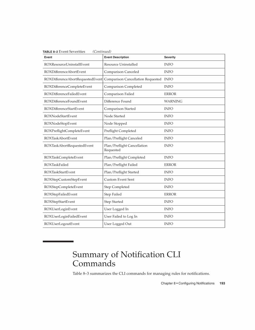
TABLE 8–2 Event Severities (Continued)Event Event Description Severity
ROXResourceUninstallEvent Resource Uninstalled INFO
ROXDifferenceAbortEvent Comparison Canceled INFO
ROXDifferenceAbortRequestedEvent Comparison Cancellation Requested INFO
ROXDifferenceCompleteEvent Comparison Completed INFO
ROXDifferenceFailedEvent Comparison Failed ERROR
ROXDifferenceFoundEvent Difference Found WARNING
ROXDifferenceStartEvent Comparison Started INFO
ROXNodeStartEvent Node Started INFO
ROXNodeStopEvent Node Stopped INFO
ROXPreflightCompleteEvent Preflight Completed INFO
ROXTaskAbortEvent Plan/Preflight Canceled INFO
ROXTaskAbortRequestedEvent Plan/Preflight CancellationRequested
INFO
ROXTaskCompleteEvent Plan/Preflight Completed INFO
ROXTaskFailed Plan/Preflight Failed ERROR
ROXTaskStartEvent Plan/Preflight Started INFO
ROXStepCustomStepEvent Custom Event Sent INFO
ROXStepCompleteEvent Step Completed INFO
ROXStepFailedEvent Step Failed ERROR
ROXStepStartEvent Step Started INFO
ROXUserLoginEvent User Logged In INFO
ROXUserLoginFailedEvent User Failed to Log In INFO
ROXUserLogoutEvent User Logged Out INFO
Summary of Notification CLICommandsTable 8–3 summarizes the CLI commands for managing rules for notifications.
Chapter 8 • Configuring Notifications 193

TABLE 8–3 Summary of the rule Commands
Command Description
rule.add Adds a notification rule.
rule.del Deletes a notification rule.
rule.la Lists all notification rules.
rule.lo Retrieves a specific rule.
rule.mod Modifies an existing rule.
194 N1 Service Provisioning System 4.1 User’s Guide • February 2004

APPENDIX A
Special Names
Reserved NamesWithin the provisioning software there are certain names that are reserved for systemuse. If you attempt to use one of the reserved names, the provisioning software willgive you an error message regarding the name.
� Paths
/system The provisioning software reserves the /system path and everythingunder it.
� Hosts
masterserver This is the Master Server.
� Host Types
crhost This the default host type.
� Component Variables
name Name of the component
description Description of the component
label Label of the component
softwareVendor Software vendor of the component definition
author Author of the component definition
� Host Types
name Name of the target host
description Description of the target host
hostTypeName The name of the host type of the target host
195

raIP IP address of the remote agent on the target host
raPort Port of the remote agent on the target host
raHomeDir The absolute path of the remote agent home directory on thetarget host
raDataDir The absolute path of the remote agent data directory on thetarget host
raTmpDir The absolute path of the remote agent temporary directory onthe target host
raConfigDir The absolute path of the remote agent config directory on thetarget host
196 N1 Service Provisioning System 4.1 User’s Guide • February 2004

Glossary
Component model: An XML representation of a component. The component model is a billof materials of the applications that includes:
� A list of resources used by the application� Install steps� Uninstall steps� Dependencies
Component: A component is a unit that is deployed to hosts in the provisioningsoftware. It comprises a build between a component model and aspecific set of resources for an application, such as a custom Javaapplication or an infrastructure software package. A component cancomprise multiple versions of an application. In this case, eachchecked-in version of the application is represented by a separatecomponent build.
Deployment: The execution of a plan, which automatically distributes a componentor components included in the plan. The deployment followsinstallation instructions set in the plan. Deployment is alwayspreceded by a preflight. If the preflight is successful, the Plan Executorwill actually deploy/install components to the target host.
Comparisons: A provisioning software feature that searches for and identifiesdifferences between hosts. There are three types of comparisons:Model to Install, Model-to-Model, Directory-to-Directory.
The install-to-install comparison examines the contents of two hosts’ filesystems and reports any differences.
The model-to-install comparison compares what the Master Serverreports is installed on a host against what is actually installed on thehost, and reports any differences.
197

A model-to-model comparison examines the deployment repository andhistory (stored on the Master Server) for two hosts, and reports anydifferences.
execNative: An optional call out to custom scripts from a plan XML.
Gold server: A reference (outside) host that contains files, directories, and otherresources comprising an application you want to deploy. Theseresources are checked in (uploaded) to the provisioning software fromthe gold server.
Host: A server connected to the provisioning software. A host can representan individual server or a set of servers.
Host set: A user-defined, logical grouping of hosts sharing one or more commonattributes, such as physical location or functional group. A definedhost set allows quick and easy application updates to all hosts in theset, as well as install-to-install comparisons between the hosts. Hostsets can be nested.
Host type: A base class of servers bound by a set of common attributes, all ofwhich are user-defined. Hosts belonging to a host type set useparticular attribute values in variable substitutions in all deployments.Host types can be used to categorize hosts into logical groupings, suchas sets of applications required for the hosts, geographic locations ofthe hosts, or functional groups. Host types also facilitate host searchesby allowing users to search for all hosts of a certain type.
Host search: A query run on the repository that yields a list of hosts whoseattributes match those specified in the query. You can use host searchesto create lists of hosts that have the same host type, are running thesame applications, are configured with the same subnet masks, and soon.
Local Distributor, or LD An engine, installed on a machine with the provisioning software, thatacts as a link between other objects, such as the Master Server toRemote Agents, the Master Server to other LDs, and another LD toRemote Agents. Designed to maximize bandwidth efficiency andspeed, LDs can also provide secure network connections fornavigating restricted environments.
Master Server, or MS: The main processing engine in the provisioning software. It is installedon a dedicated machine at a central location, where it can connect toany of the data center environments. The MS provides the centralizeddata storage, data processing, and user interfaces.
Plan: An XML representation of the deployment script that referencescomponents to be deployed. A plans include:
� Install/uninstall steps.� Start/Stop components (optional).� Verification steps (optional)
198 N1 Service Provisioning System 4.1 User’s Guide • February 2004

� ExecNatives (optional)
Plan executor: The provisioning software’s deployment engine. It handles preflightsand actual deployments.
Preflight: A test “deployment” of a plan to a simulated UNIX environment that:
� Checks availability and connectivity of target hosts.� Confirms permissions.� Validates dependencies.
A preflight finds and reports any errors or potential errors that couldaffect the actual deployment. Preflights always automatically proceed adeployment; they can also be run as standalone procedures that arenot automatically followed by a deployment.
Remote Agent, or RA: An engine installed on any machine in the provisioning software towhich components are deployed. On that machine, the RA managestasks such as installing software, controlling services, collectinginformation to send back to the MS.
Resources: Files that are deployed to hosts when a plan is executed.
Resource types: Built-in resource categories identified and supported by theprovisioning software. When a resource is checked in, it must betagged with the appropriate resource type. Resource types includefiles, directories, IIS Types, and COM+ components.
Snapshot: A capture of resources stored on a Remote Agent during adeployment. The snapshot is used during comparisons between hosts(install-to-install) or between a host and the model of the host on theMaster Server (model-to-install).
Verification step: An optional URL or process test that can be run at the end of adeployment to ensure successful completion of the plan.
Glossary 199

200 N1 Service Provisioning System 4.1 User’s Guide • February 2004

Index
CCanceling a comparison, 183Comparisons, 169
canceling, 183ignoring directories or files, 182Model to Directory, 171Model to Model, 170synchronization, 173Types, 170
DDirectory to Directory comparisons
using scripts, 172prepare and cleanup, 172
EEvent messages, 189Event severities, 189Excluding files and directories from
comparisons, 182
MModel to Directory comparison, 171
snapshots, 171Model to Model comparisons, 170
NNotification rules
event messages, 189event severities, 189event severities table, 192overview, 185
PPhysical Hosts, 62Preparing Hosts, 62
RROXComponentControlServiceEvent, 190ROXComponentInstallEvent, 190ROXComponentUninstallEvent, 190ROXDifferenceAbortEvent, 190ROXDifferenceAbortRequestedEvent, 190ROXDifferenceCompleteEvent, 190ROXDifferenceFailedEvent, 190ROXDifferenceFoundEvent, 191ROXDifferenceProgressEvent, 191ROXDifferenceStartEvent, 191ROXErrorEvent, 190ROXInfoEvent, 190ROXNodeStartEvent, 191ROXNodeStopEvent, 191ROXPreflightCompleteEvent, 191ROXResourceInstallEvent, 190ROXResourceUninstallEvent, 190
201

ROXStepCompleteEvent, 191ROXStepCustomStepEvent, 191ROXStepFailedEvent, 192ROXStepProgressEvent, 192ROXStepStartEvent, 192ROXTaskAbortEvent, 191ROXTaskAbortRequestedEvent, 191ROXTaskCompleteEvent, 191ROXTaskFailedEvent, 191ROXTaskProgressEvent, 191ROXTaskStartEvent, 191ROXTaskTimeoutEvent, 191ROXUserLoginEvent, 192ROXUserLoginFailedEvent, 192ROXUserLogoutEvent, 192ROXWarningEvent, 190
SSnapshots, 169
VVirtual Hosts, 62
202 N1 Service Provisioning System 4.1 User’s Guide • February 2004