N 455 - c-a-b.org.uk · prEN 13830-rev:2013 (E) 5 . Foreword . This document (EN 13830) has been...
80
CEN/TC 33/WG 6 N 455 CEN/TC 33/WG 6 CEN/TC 33/WG 6 - Curtain walling Email of secretary: Secretariat: UNI (Italy) doc.WG6 0455-prEN 13830 Curtain walling Product Standard – (up to 23rd April 2014) Document type: Committee draft Date of document: 2014-04-23 Expected action: ACT Action due date: 2014-04-28 Background: Committee URL: http://cen.iso.org/livelink/livelink/open/centc33wg6
Transcript of N 455 - c-a-b.org.uk · prEN 13830-rev:2013 (E) 5 . Foreword . This document (EN 13830) has been...

CEN/TC 33/WG 6 N 455
CEN/TC 33/WG 6CEN/TC 33/WG 6 - Curtain wallingEmail of secretary: Secretariat: UNI (Italy)
doc.WG6 0455-prEN 13830 Curtain walling Product Standard – (up to 23rd April 2014)
Document type: Committee draft
Date of document: 2014-04-23
Expected action: ACT
Action due date: 2014-04-28
Background:
Committee URL: http://cen.iso.org/livelink/livelink/open/centc33wg6

Document type: European Standard Document subtype: Document stage: Formal Vote Document language: E
CEN/TC 33
Date: 2013-02
prEN 13830-rev:2013
CEN/TC 33
Secretariat: AFNOR
Curtain Walling — Product standard
Vorhangfassaden — Produktnorm
Façades rideaux — Norme de produit
ICS:
Descriptors:
MonicaBoscaino
Text Box
CEN TC33 WG6 n. 0455

prEN 13830-rev:2013 (E)
2
Contents
Page
Foreword ..............................................................................................................................................................5
Introduction .........................................................................................................................................................5
1 Scope ......................................................................................................................................................5
2 Normative references ............................................................................................................................6
3 Terms, definitions and abbreviated terms ..........................................................................................9
4 Product characteristics ...................................................................................................................... 11 4.1 Reaction to fire (of components, when relevant) ............................................................................ 11 4.2 Fire resistance ..................................................................................................................................... 11 4.3 Fire propagation (to upper levels) ..................................................................................................... 11 4.4 Watertightness .................................................................................................................................... 12 4.5 Resistance to its own dead load ....................................................................................................... 12 4.6 Wind load resistance .......................................................................................................................... 12 4.7 Resistance to snow load (only for elements subjected to snow load) ......................................... 12 4.8 Impact resistance................................................................................................................................ 13 4.9 Resistance to live horizontal loads at sill level ............................................................................... 13 4.10 Seismic resistance ............................................................................................................................. 13 4.11 Thermal shock resistance .................................................................................................................. 14 4.12 Direct airborne sound insulation ...................................................................................................... 14 4.13 Flanking sound transmission ............................................................................................................ 14 4.14 Thermal transmittance ....................................................................................................................... 14 4.15 Air permeability ................................................................................................................................... 14 4.16 Water vapour permeability ................................................................................................................. 14 4.17 Radiation properties ........................................................................................................................... 14 4.18 Equipotential bonding (protection against electric shock) (where specifically required) .......... 14 4.19 Durability ............................................................................................................................................. 15 4.19.1 Durability of watertightness .............................................................................................................. 15 4.19.2 Durability of thermal transmittance .................................................................................................. 15 4.19.3 Durability of air permeability ............................................................................................................. 15
5 Testing, assessment and sampling methods .................................................................................. 15 5.1 Sampling .............................................................................................................................................. 15 5.1.1 Sequence of testing ............................................................................................................................ 16 5.2 Reaction to fire (of components, when relevant) ............................................................................ 17 5.3 Fire resistance ..................................................................................................................................... 17 5.4 Fire propagation (to upper levels) ..................................................................................................... 17 5.5 Watertightness .................................................................................................................................... 17 5.6 Resistance to its own dead load ....................................................................................................... 17 5.7 Wind load resistance .......................................................................................................................... 18 5.8 Resistance to snow load (only for elements subject to snow load) .............................................. 18 5.9 Impact resistance................................................................................................................................ 18 5.10 Resistance to live horizontal loads at sill level ............................................................................... 18 5.11 Seismic resistance ............................................................................................................................. 19 5.11.1 Safety in use ........................................................................................................................................ 19 5.11.2 Serviceability (where specially required) ......................................................................................... 19 5.12 Direct airborne sound insulation ...................................................................................................... 19 5.13 Flanking sound transmission ............................................................................................................ 19 5.14 Thermal transmittance ....................................................................................................................... 19 5.15 Air permeability ................................................................................................................................... 19 5.16 Radiation properties ........................................................................................................................... 20

prEN 13830-rev:2013 (E)
3
5.17 Equipotential bonding (protection against electric shock) (where specifically required) ........... 20 5.18 Durability .............................................................................................................................................. 20 5.18.1 Durability of watertightness ............................................................................................................... 20 5.18.2 Durability of thermal transmittance ................................................................................................... 21 5.18.3 Durability of air permeability .............................................................................................................. 21
6 Assessment and verification of constancy of performance (AVCP) ............................................. 21 6.1 General ................................................................................................................................................. 21 6.2 Type testing ......................................................................................................................................... 22 6.2.1 General ................................................................................................................................................. 22 6.2.2 Test samples, testing and compliance criteria ................................................................................ 22 6.2.3 Test reports .......................................................................................................................................... 24 6.2.4 Cascading determination of the product type results ..................................................................... 24 6.3 Factory production control (FPC) ...................................................................................................... 25 6.3.1 General ................................................................................................................................................. 25 6.3.2 Requirements ....................................................................................................................................... 25 6.3.3 Product specific requirements ........................................................................................................... 28 6.3.4 Initial inspection of factory and of FPC ............................................................................................. 29 6.3.5 Continuous surveillance of FPC (only for curtain walling kits covered by AVCP system 1) ...... 29 6.3.6 Procedure for modifications............................................................................................................... 29 6.3.7 One-off products, pre-production products (e.g. prototypes) and products produced in
very low quantity ................................................................................................................................. 30
7 Marking, labelling ................................................................................................................................ 31
Annex A (informative) Maintenance .............................................................................................................. 32
Annex B (informative) Equipotential bonding conditions ........................................................................... 33 B.1 General Requirements ........................................................................................................................ 33 B.2 Connectors ........................................................................................................................................... 33
Annex C (informative) Resistance to actions: guidance on the use of Eurocodes.................................. 34 C.1 Introduction of the Annex ................................................................................................................... 34 C.2 Scope of the Annex ............................................................................................................................. 34 C.3 Symbols and abbreviations in the Annex ......................................................................................... 34 C.4 Definition and principle ....................................................................................................................... 35 C.4.1 Classes of consequence..................................................................................................................... 35 C.4.2 Curtain walling kit operating as safety barrier ................................................................................. 36 C.4.3 Loaded area "A" .................................................................................................................................. 36 C.5 Requirements ....................................................................................................................................... 38 C.6 Actions.................................................................................................................................................. 38 C.6.1 Dead load action .................................................................................................................................. 38 C.6.2 Wind action .......................................................................................................................................... 38 C.6.3 Actions for curtain walling serving as parapets .............................................................................. 38 C.7 Assumptions related the combinations of actions .......................................................................... 40 C.7.1 Combinations of actions: generalities .............................................................................................. 40
Annex D (normative) Seismic resistance ...................................................................................................... 43 D.1 General principles ............................................................................................................................... 43 D.1.1 Required performance limits .............................................................................................................. 43 D.1.2 Factors affecting seismic performance ............................................................................................ 43 D.2 Assessment of seismic serviceability limit ...................................................................................... 43 D.3 Assessment of seismic safety limit ................................................................................................... 44 D.4 Seismic movement regime ................................................................................................................. 44 D.4.1 Principles.............................................................................................................................................. 44 D.4.2 Test apparatus ..................................................................................................................................... 45 D.4.3 Test procedure ..................................................................................................................................... 45
Annex E (normative) Selection, preparation, mounting and fixing of test specimen for reaction to fire tests of curtain walling and field of direct application .............................................................. 48
E.1 General ................................................................................................................................................. 48 E.2 EN ISO 11925-2:2010 (Single flame test) ........................................................................................... 49 E.2.1 Profile .................................................................................................................................................... 49
prEN 13830-rev:2013 (E)
4
E.2.2 Infill ....................................................................................................................................................... 50 E.2.3 Sealing between infill and profile ...................................................................................................... 51 E.2.4 Organic coating/top layers ................................................................................................................ 52 E.3 Mounting and fixing for EN 13238 (SBI-test) .................................................................................... 52 E.4 EN ISO 1182 (Non-combustibility test) ............................................................................................. 53 E.5 EN ISO 1716 (Determination of the heat of combustion) ................................................................ 54 E.6 Field of direct application .................................................................................................................. 54
Annex F (normative) Characteristics and range of direct application ...................................................... 55 F.1 Selection of a representative test specimen .................................................................................... 58
Annex G (informative) Requirements Characteristics and performances of curtain walling kit ........... 61
Annex H (informative) Interchangeability between characteristics and components ............................ 63
Annex I (informative) Basic approach to durability .................................................................................... 65
Annex ZA (informative) Clauses of this standard addressing the provisions of the EU Construction Product Regulation ..................................................................................................... 67
ZA.1 Scope and relevant characteristics....................................................................................................... 67 ZA.2 Procedure for AVCP of curtain walling kit ........................................................................................... 70 ZA.2.1 System(s) of AVCP .............................................................................................................................. 70 ZA.2.2.2 Declaration of performance (DoP) .................................................................................................. 72 ZA.2.2.2 Content ............................................................................................................................................... 72
ZA.3 CE Marking and labelling ....................................................................................................................... 76
Bibliography ..................................................................................................................................................... 79

prEN 13830-rev:2013 (E)
5
Foreword
This document (EN 13830) has been prepared by Technical Committee CEN/TC 33 “Doors, windows, shutters, building hadware and curtain walling”, the secretariat of which is held by AFNOR.
This document supersedes EN 13830:2003.
This document has been prepared under a mandate given to CEN by the European Commission and the European Free Trade Association, and supports essential requirements of EU Directive(s).
For relationship with EU Directive(s), see informative Annexe ZA which is integral parts of this document.
The new revision extends the scope to sloping parts included in the curtain walling kit and clarifies the exclusion of the following products:
⁻ “Patent glazing” (glazed sloping roofs) kits;
⁻ Roof glazing constructions;
⁻ Façades made of precast concrete panels as part of the wall (see EN 14992).
Here below the list the most important changes compared with the previous version EN 13830:2003:
⁻ new characteristics were added;
⁻ new annexes were introduced, particularly the one for the range of direct application of characteristics (extension rules);
⁻ the durability was dealt in details in Annex I;
⁻ updated clause 6 and Annex ZA with the provisions of the EU Construction Product Regulation No. 305/2011.
Introduction
This European Standard specifies the technical characteristics of curtain walling kit and includes a systematic framework of requirements, test methods and compliance criteria to allow the product to fulfil with it.
Curtain walling kit might not be completed in all respects within a manufacturing area, and some kit components could be supplied separately on site. Curtain walling kit could be also preassembled in plant(s) as prefabricated units.
1 Scope
This European Standard specifies requirements of curtain walling kit intended to be used as a building envelope to provide weather resistance, safety in use and energy economy and heat retention and provides test/assessments/calculation methods and compliance criteria of the related performances.
The curtain walling kit covered by this standard shall fulfil its own integrity and mechanical stability but does not contribute to the load bearing or stability of the main building structure, and could be replaced independently of it.

prEN 13830-rev:2013 (E)
6
This standard applies to curtain walling kit ranging from a vertical position to ±15° from the vertical. Any sloping parts should be contained within the curtain walling kit.
This standard is applicable to the whole of the curtain walling kits, including the fixings.
Curtain walling according to this standard is intended to be used as part of the building envelope.
This European Standard does not include:
“Patent glazing” (glazed sloping roofs) kits;
Roof glazing constructions;
Façades made of precast concrete panels as part of the wall (see EN 14992);
NOTE precast concrete panels may be used in curtain walling kits as infill panels.
NOTE Durability of structural sealed glazing infills is not covered by this standard.
2 Normative references
The following documents, in whole or in part, are normatively referenced in this document and are indispensable for its application. For dated references, only the edition cited applies. For undated references, the latest edition of the referenced document (including any amendments) applies.
EN 1096-2, Glass in building - Coated glass - Part 2: Requirements and test methods for class A, B and S coatings
EN 1096-3, Glass in building - Coated glass - Part 3: Requirements and test methods for class C and D coatings
EN 1096-4, Glass in building - Coated glass - Part 4: Evaluation of conformity/Product standard
EN 1279-1, Glass in Building - Insulating glass units - Part 1: Generalities, dimensional tolerances and rules for the system description
EN 1279-2, Glass in building - Insulating glass units - Part 2: Long term test method and requirements for moisture penetration
EN 1279-3, Glass in building - Insulating glass units - Part 3: Long term test method and requirements for gas leakage rate and for gas concentration tolerances
EN 1279-4, Glass in building - Insulating glass units - Part 4: Methods of test for the physical attributes of edge seals
EN 1279-5, Glass in building - Insulating glass units - Part 5: Evaluation of conformity
EN 1364-3, Fire resistance tests for non-loadbearing elements - Part 3: Curtain walling – Full configuration (complete assembly)
EN 1364-4, Fire resistance tests for non-loadbearing elements - Part 4: Curtain walling - Part configuration water spray
EN 1990, Eurocode - Basis of structural design

prEN 13830-rev:2013 (E)
7
EN 1991-1-1, Eurocode 1: Actions on structures – Part 1-1: General actions – Densities, self-weight, imposed loads for buildings
EN 1991-1-3, Eurocode 1: Actions on structures - Part 1-3: General actions - Snow loads
EN 1991-1-4, Eurocode 1: Actions on structures - Part 1-4: General actions - Wind actions
EN 1998-1, Eurocode 8: Design of structures for earthquake resistance - Part 1: General rules, seismic actions and rules for buildings
EN 12152, Curtain walling - Air permeability - Performance requirements and classification
EN 12153, Curtain walling - Air permeability - Test method
EN 12154, Curtain walling - Watertightness - Performance requirements and classification
EN 12155, Curtain walling - Watertightness – Laboratory test under static pressure
EN 12179, Curtain walling - Resistance to wind load - Test method
EN 12354-1, Glass in building - Laminated glass and laminated safety glass - Definitions and description of component parts EN 12365-1, Building hardware - Gasket and weatherstripping for doors, windows, shutters and curtain walling - Part 1: Performance requirements and classification
EN 12365-4, Building hardware – Gasket and weatherstripping for doors, windows, shutters and curtain walling - Part 4: Recovery after accelerated ageing test method
EN 12567-1, Thermal performance of windows and doors - Determination of thermal transmittance by the hot-box method - Part 1: Complete windows and doors EN 12600, Glass in building - Pendulum test - Impact test method and classification for flat glass
EN 12758, Glass in building - Glazing and airborne sound insulation - Product descriptions and determination of properties
EN 13022-1, Glass in building - Structural sealant glazing - Part 1: Glass products for structural sealant glazing systems for supported and unsupported monolithic and multiple glazing
EN 13022-2, Glass in building - Structural sealant glazing - Part 2: Assembly rules
EN 13050, Curtain Walling - Watertightness - Laboratory test under dynamic condition of air pressure and water spray
EN 13116, Curtain walling - Resistance to wind load - Performance requirements
EN 13119, Curtain walling – Terminology
EN 13162, Thermal insulation products for buildings - Factory made mineral wool (MW) products - Specification
EN 13163, Thermal insulation products for buildings - Factory made expanded polystyrene (EPS) products - Specification
EN 13164, Thermal insulation products for buildings - Factory made extruded polystyrene foam (XPS) products - Specification

prEN 13830-rev:2013 (E)
8
EN 13165, Thermal insulation products for buildings - Factory made rigid polyurethane foam (PU) products - Specification
EN 13166, Thermal insulation products for buildings - Factory made phenolic foam (PF) prodcts - Specification
EN 13167, Thermal insulation products for buildings - Factory made cellular glass (CG) products - Specification
EN 13168, Thermal insulation products for buildings - Factory made wood wool (WW) products - Specification
EN 13169, Thermal insulation products for buildings - Factory made expanded perlite board (EPB) products - Specification
EN 13170, Thermal insulation products for buildings - Factory made products of expanded cork (ICB) - Specification
EN 13171, Thermal insulating products for buildings - Factory made wood fibre (WF) products – Specification
EN 13363-1, Solar protection devices combined with glazing - Calculation of solar and light transmittance - Part 1: Simplified method
EN 13363-2, Solar protection devices combined with glazing - Calculation of total solar energy transmittance and light transmittance - Part 2: Detailed calculation method
EN 13501-1, Fire classification of construction products and building elements - Part 1: Classification using data from reaction to fire tests
EN 13501-2, Fire classification of construction products and building elements - Part 2: Classification using data from fire resistance tests, excluding ventilation services
EN 14019, Curtain walling - Impact resistance - Performance requirements
EN 14509, Self-supporting double skin metal faced insulating panels - Factory made products – Specifications
EN 15434, Glass in building - Product standard for structural and/or ultra-violet resistant sealant (for use with structural sealant glazing and/or insulating glass units with exposed seals)
EN 15651-1, Sealants for non-structural use in joints in buildings and pedestrian walkways - Part 1: Sealants for facade elements
EN 15651-2, Sealants for non-structural use in joints in buildings and pedestrian walkways - Part 2: Sealants for glazing
EN 62305, Protection against lightning
EN ISO, 717-1, Acoustics – Rating of sound insulation in buildings and of building elements – Part 1: Airborne sound insulation
EN ISO 1182, Reaction to fire tests for building products - Non combustibility test EN ISO 1716, Reaction to fire tests for building products - Determination of the heat of combustion EN ISO 8339, Building construction – Sealants – Determination of tensile properties (Extension to break)
EN ISO 8340, Building construction - Sealants - Determination of tensile properties at maintained extension
EN ISO 9046, Building construction - Jointing products - Determination of adhesion/cohesion properties of sealants at constant temperature

prEN 13830-rev:2013 (E)
9
EN ISO 9047, Building construction - Jointing products - Determination of adhesion/cohesion properties of sealants at variable temperatures
EN ISO 10140-2, Acoustics - Laboratory measurement of sound insulation of building elements - Part 2: Measurement of airborne sound insulation EN ISO 10140-3, Acoustics – Measurement of sound insulation in buildings and of building elements – Part 3: Laboratory measurements of airborne sound insulation of building elements
EN ISO 10140-5, Acoustics - Measurement of sound insulation in buildings and of building elements - Part 5: Field measurements of airborne sound insulation of façade elements and façades
EN ISO 10590, Building construction - Sealants - Determination of tensile properties of sealants at maintained extension after immersion in water
EN ISO 10591, Building construction - Sealants - Determination of adhesion/cohesion properties of sealants after immersion in water
EN ISO 10848-1, Acoustics - Laboratory measurement of the flanking of airborne and impact sound between adjoining rooms - Part 1: Frame document
EN ISO 10848-2, Acoustics - Laboratory measurement of the flanking transmission of airborne and impact sound between adjoining rooms - Part 2: Application to light elements when the junction has a small influence
EN ISO 11600, Building construction - Jointing products - Classification and requirements for sealants
EN ISO 11925-2:2010 Reaction to fire tests - Ignitability of building products subjected to direct impingement of flame - Part 2: Single-flame source test EN ISO 12631, Thermal performances of curtain walling - Calculation of thermal transmittance - Simplified method
3 Terms, definitions and abbreviated terms
3.1 Definitions
For the purposes of this document, the terms and definitions given in EN 1279-1, EN 13022-1, EN 13022-2, EN 13119, EN 15434 and the following apply.
3.1.1 curtain walling a part of the building envelope made of a framework usually consisting of horizontal and vertical profiles, connected together and anchored to the supporting structure of the building, and containing fixed and/or openable infills, which provides all the required functions of an internal or external wall or part thereof, but does not contribute to the load bearing or the stability of the structure of the building. Curtain walling is designed as a self-supporting construction which transmits dead-loads and imposed loads to the main building structure
3.1.2 curtain walling kit a defined set of components and/or assemblies that when installed on a building, form curtain walling
3.1.3 double skin curtain walling a type of curtain walling kit comprising inner and outer skins and an air cavity, the whole designed as an integrated system fulfilling the functions of the curtain walling kit

prEN 13830-rev:2013 (E)
10
3.1.4 curtain walling system a defined set of components from which a curtain walling kit may be created for subsequent installation on a building. It can give rise to one or more different kits
3.1.5 curtain walling kit of similar design a curtain walling kit in which the replacement of components (e.g. glazing, hardware, gaskets and sealants), and/or a change of material specification and/or dimensional change of profile section and/or methods and means of assembly which will not adversely affect the classification and/or declared value of a performance characteristic
NOTE Certain modifications might cause more favourable values for one or more characteristics, but also more
unfavourable values for other characteristics (see Annex H)
3.1.6 patent glazing kits patent glazing is a system of ventilated glazing in which the glass, often supported on only two edges with open joints, is dry glazed and does not provide an air seal
3.1.7 sloping parts of curtain walling kit parts of curtain walling kit tilted more than 15° from the vertical
Key
1 curtain walling – ranging from a vertical position to ±15° from the vertical
2 sloping part not included in curtain walling kit (roof glazing construction)
3 sloping part included within curtain walling kit
Figure 1: sloping parts of curtain walling kit
3.1.8 sill height (for panels that include openable/fixed infills) the height from the finished floor level at which the live horizontal loads are applied for calculation or testing, whether or not there is a framing member at that level

prEN 13830-rev:2013 (E)
11
3.1.9 curtain walling framework curtain walling kits assembled using frames, supporting frames and brackets are not loadbearing structures insofar they are designed as a self supporting framework transferring loads to the main building structure
3.1.10 composite infill panel (sandwich panel) Non-transparent infill panel incorporated into the framework of curtain walling consisting of two faces positioned on either side of a core that might be made of thermal insulating material, bonded to both faces on a way that these components act compositely when under load
3.1.11 non-composite infill panel Non-transparent infill panel incorporated into the framework of curtain walling not acting compositely when under load. It might comprise an outer pane, a spacer, a core, a vapour barrier and an inner back pane
3.1.12 openable infill transparent or non-transparent element incorporated into the framework of curtain walling that can be both opened and closed
NOTE Openable infills are generally dealt with in the relevant product standard, e.g. in EN 14351-1, EN 12101, EN
13241-1, etc, and they shall be tested accordingly
3.2 Abbreviations used in this standard
AVCP Assessment and Verification of Constancy of Performance
FPC Factory Production Control
DoP Declaration of Performance
IGU Insulating Glass Unit
NPD No Performance Determined
REACH Registration, Evaluation, Authorisation and Restriction of Chemicals
CEN European Committee for Standardization (fr.: Comité Européen de Normalisation)
CWFT Classification without further testing
4 Product characteristics
4.1 Reaction to fire (of components, when relevant)
When relevant, response of components used in curtain walling kit in contributing by their own decomposition to a fire to which they are exposed, under specified conditions.
When tested in accordance with 5.2, results shall be classified according to 5.2.
4.2 Fire resistance
Ability of the curtain walling kit to provide integrity (E), integrity and insulation (EI) and integrity and radiation (EW) in the event of fire, for a given period of time.
When tested in accordance with the test methods indicated in 5.3, the results shall be classified according to 5.3.
4.3 Fire propagation (to upper levels)
Ability of curtain walling kit to limit the spread of fire and smoke to adjacent parts of the same works for a certain amount of time in relation to one or more of characteristics listed above.

prEN 13830-rev:2013 (E)
12
The curtain walling kit shall limited the transmission of fire and smoke through voids in the curtain construction at its abutment at all levels with structural floor slabs and walls.
When tested in accordance with the test methods indicated in 5.4, the results shall be classified according 5.4.
4.4 Watertightness
Ability of the curtain walling kit to prevent rain water penetration into the building that could affect the hygiene and health indoor conditions. Any water entering the curtain walling should not be retained within the curtain walling and drained outside.
When tested in accordance with 5.5, results shall be classified according to Table 1 of 5.5.
4.5 Resistance to its own dead load
Ability of the curtain walling kit to support its self-weight including any attachments incorporated into it by original design. It shall transfer the weight to the building structure via the fixings intended for that purpose.
NOTE 1 The design dead loads likely to act upon the curtain walling kit shall be calculated in accordance with EN 1991-1-1 taking into account the nationally determined parameters relevant to the place of use. For the application of the
relevant Eurocodes to the design of curtain walling kit see Annex C.
NOTE 2 The engineering stresses induced into infills, framing components, structural brackets and fixings shall be no
greater than those specified within the appropriate materials standard from which the components and brackets are made. The engineering stresses shall be calculated in accordance with the appropriate Eurocodes taking into account the
nationally determined parameters relevant to the place of use; principles of their application are given in Annex C.
When calculated in accordance with 5.6, results shall be declared.
4.6 Wind load resistance
Ability of the curtain walling kit to resist the difference of air pressure between inside and outside, both positive and negative, without damage, permanent deformation.
When tested in accordance to 5.7, results shall be declared.
The curtain walling kit shall transfer the declared wind loads to the building’s structure, safely, via the fixings intended for that purpose.
NOTE 1 The design wind loads likely to act upon the curtain walling kit should be calculated in accordance with EN
1991-1-4 taking into account the nationally determined parameters relevant to the place of use. For the application of the relevant Eurocodes to the design of curtain walling kit, see Annex C.
NOTE 2 The stiffness of the curtain walling kit should be determined by calculation. When calculating the rigidity of the curtain walling kit no account should be taken of the potential stiffening effect of the glass.
4.7 Resistance to snow load (only for elements subjected to snow load)
Ability of the curtain walling kit to resist snow loads.
When calculated in accordance to 5.8, results shall be declared.
NOTE 1 The design snow loads likely to act upon the curtain walling kit shall be calculated in accordance with EN 1991-1-3 taking into account the nationally determined parameters relevant to the place of use.
For the application of the relevant Eurocodes to the design of curtain walling kit, see Annex C.
NOTE 2 The stiffness of the curtain walling kit shall be determined by calculation. When calculating the rigidity of the
curtain walling kit no account shall be taken of the potential stiffening effect of the glass.

prEN 13830-rev:2013 (E)
13
4.8 Impact resistance
Ability of the curtain walling kit to resist under soft body impact.
4.8.1 Internal
Ability of the curtain walling kit to maintain its integrity under internal impact load.
When tested in accordance to 5.9, results shall be classified according to Table 2 of 5.9.
4.8.2 External
Ability of the curtain walling kit to maintain its integrity under external impact load.
When tested in accordance to 5.9, results shall be classified according to Table 2 of 5.9.
4.9 Resistance to live horizontal loads at sill level
Ability of the curtain walling to resist live horizontal load at sill height as specified in EN 1991-1-1.
NOTE 1 For calculation and testing, the sill height shall not be greater than 1,20 m, in accordance with EN 1991-1-1.
NOTE 2 The design live horizontal loads likely to act upon the curtain walling kit shall be calculated in accordance with
EN 1991-1-1 taking into account the nationally determined parameters relevant to the place of use.
For the application of the relevant Eurocodes to the design of curtain walling kit, see Annex C.
NOTE 3 The stiffness of the curtain walling kit shall be determined by calculation. When calculating the stiffness of the
curtain walling kit no account shall be taken of the potential stiffening effect of the glass.
When calculated in accordance with 5.10, results shall be declared.
4.10 Seismic resistance
Ability of the curtain walling to withstand a seismic action having a larger probability of occurrence than the design seismic action, without risks to persons, the occurrence of damage and the associated limitations of use, in accordance with EN 1998-1, 2.1.
4.10. 1 Safety in use
Ability of the curtain walling to:
A. Resist the inertia forces caused by the declared seismic action. The fixings shall transfer the inertia forces to the supporting structure.
B. Have movement accommodation to prevent failure of the infill panels, frame connections or fixings as a result of the declared seismic action. When tested in accordance with 5.11.1, results must comply with 5.11.1.
No components of the curtain walling kit shall separate and fall from the curtain walling kit as a result of the declared seismic safety limit, unless it has been specifically evaluated that it is safe for them to do so.
4.10.2 Serviceability (where specially required)
Where specifically required, ability of the curtain walling to remain serviceable following the declared seismic action of shorter return period (see EN 1998-1, 2.1). When tested in accordance with 5.11 the watertightness and the air permeability classes shall confirm those measured according to 4.4 and 4.14.
When tested in accordance with 5.11.2, results shall be declared.

prEN 13830-rev:2013 (E)
14
4.11 Thermal shock resistance
Where specifically required Where it is determined that a suitable glass resistant to thermal shock is required shall be chosen which conforms in accordance to the appropriate European Standard(s) and the type of glass (i.e. heat-strengthened or toughened glass) shall be declared.
4.12 Direct airborne sound insulation
Ability of the curtain walling kit to acoustically insulate the interior from direct airborne external noise.
When tested in accordance with 5.12, results shall be declared.
4.13 Flanking sound transmission
Ability of the curtain walling kit to mitigate the propagation through the façade of noise produced in an adjacent space.
When tested in accordance to 5.13, results shall be declared.
4.14 Thermal transmittance
Ability of the curtain walling kit to reduce energy losses through it and to contribute to the global indoor thermal comfort.
When assessed in accordance to 5.14, results shall be declared.
4.15 Air permeability
Ability of the curtain walling kit to limit energy loss due to the airflow through it.
When tested in accordance to 5.15, results shall be classified according to Table 3 of 5.15.
4.16 Water vapour permeability
For non transparent infill panel, a vapour control layer barrier shall be chosen which conform to the appropriate European Standard shall take into account in accordance with the specified hydro-thermal conditions of the building, and the type of vapour control layer shall be declared.
4.17 Radiation properties
Ability of the curtain walling kit to control the total solar energy transmittance (solar factor, g-value) and light transmittance of transparent and translucent parts.
When assessed in accordance to 5.16, results shall be declared.
4.18 Equipotential bonding (protection against electric shock) (where specifically required)
Equipotentialization is the method to avoid dangerous touch voltages (electric shock).
Where specifically required, equipotentialization is achieved by electric interconnecting of:
metal components of curtain walling kit;
external conductive parts and lines connected to the structure;
electric and electronic systems via SPD (Surge Protective Device).

prEN 13830-rev:2013 (E)
15
The minimum dimensions or minimum electrical resistance of conductors connecting metal installations are to be seen in normative annex B.
Any components which are electrical insulated from the framing do not need to be connected.
NOTE Lightning equipotential bonding according EN 62305 needs more measures and is not taken into account.
When assessed in accordance to 5.17, results shall be declared.
4.19 Durability
Ability of the curtain walling kit to maintain its required performance of essential characteristics under the influence of foreseeable actions. Subject to normal maintenance, the product shall enable a properly designed and executed works to fulfil the Essential Requirements for an economically reasonable period of time (working life of the product).
The manufacturer shall provide information about maintenance and replaceable parts, see Annex A.
In either case, the underlying assumption is that the performance of the product will be maintained at an acceptable level, in relation to its initial performance, throughout its working life, see Annex I.
NOTE Foreseeable actions represent potential degradation factors that may affect the compliance of the works with the Essential Requirements. They include, weathering, ageing and UV action (i.e. actions related to “normal” agents that
could be expected to act on the works or parts thereof).
4.19.1 Durability of watertightness
Durability of watertightness shall be against, ageing and it depends mainly on the gaskets, weatherstrippings and sealant.
When assessed in accordance to 5.18.1, results must comply with 5.18.1.
4.19.2 Durability of thermal transmittance
Durability of thermal transmittance shall be against:
ageing and UV action and it is mainly linked to long-term performance of the glazing (Low Emissivity Coated Glass and Insulated Glass Units);
ageing and it is mainly linked to long-term performance of core thermal insulation products.
When assessed in accordance to 5.18.2, results must comply with 5.18.2.
4.19.3 Durability of air permeability
Durability of air permeability shall be against weathering, ageing and UV action and it depends mainly on gaskets, weatherstrippings and sealants.
When assessed in accordance to 5.18.3, results must comply with 5.18.3.
5 Testing, assessment and sampling methods
5.1 Sampling
The samples selected for testing shall be representative of the product family, taking into account 3.1.4 and Annex F as well as the product descriptions. For the purpose of sampling and testing the manufacturer shall

prEN 13830-rev:2013 (E)
16
have the option of declaring one product from the product family as representative for the whole family or part of it provided that this product has the more unfavourable combination of performance characteristics.
NOTE A product may be in different families for different characteristics.
Where a range of tests is to be carried out a sufficient number of samples shall be selected to take account of the destructive nature of the tests (see Annex F). Annex F specifies the number of test specimens (samples) required for each test and any change in size that is allowed for similar designs. Suitable test sequence for curtain walling kit is identified in 5.1.1.
5.1.1 Sequence of testing
Weather resistance tests are interdependent on each other. The following groups of tests carried out in sequence shall be considered as a single weather test. All tests shall be carried out strictly in sequence, as follows.
No test in the sequence shall be carried out unless all previous tests have been passed to the acceptance criteria.
Method A:
a) Air permeability – for classification;
b) Watertightness, under static pressure – for classification;
c) Wind load resistance – serviceability;
d) Air permeability – repeat to confirm classification after wind load resistance test classification;
e) Watertightness - repeat to confirm classification after wind load resistance test classification;
f) Wind load resistance, increased wind resistance test – safety.
Method B (where specifically required):
a) Air permeability – for classification;
b) Watertightness, under static pressure – for classification;
c) Resistance to wind load – serviceability;
d) Air permeability – repeat to confirm classification after wind load resistance test classification;
e) Watertightness - repeat to confirm classification after wind load resistance test classification;
Where specifically required, individual tests from f) to l) with the exception of j) may be added or omitted upon request. If g) is chosen, h), i) and l) have to be performed.
f) Watertightness, under dynamic pressure – for classification according to EN 13050;
g) seismic movement regime described in Annex D;
h) Air permeability – repeat to confirm classification after seismic serviceability limit test;
i) Watertightness – repeat to confirm classification after seismic serviceability limit test;
j) Resistance to wind load, increased wind resistance test – safety.

prEN 13830-rev:2013 (E)
17
Individual tests of k) and l) may be performed separately from the sequence above.
k) Impact resistance/safe breakage – for classification
l) seismic movement – safety limit.
5.2 Reaction to fire (of components, when relevant)
When relevant, the reaction to fire test shall be carried out in accordance with the test method relevant for the class claimed by the manufacturer. Test results are classified according to EN 13501-1.
The materials to be considered belonging to the Class A1 without test are listed in the EC Decision 96/603/EC (as amended).
For the conditions for mounting and fixing for the relevant test procedure and the field of direct application see Annex E.
5.3 Fire resistance
Curtain walling kit (complete assembly) shall be tested in accordance with EN 1364-3. Partial configuration of curtain walling kit shall be tested in accordance with EN 1364-4.
The performance shall be classified in accordance with EN 13501-2.
5.4 Fire propagation (to upper levels)
Partial configuration of curtain walling kit shall be tested in accordance with EN 1364-4.
Test results shall be classified in accordance with EN 13501-2.
5.5 Watertightness
A watertightness test shall be carried out in accordance with EN 12155. The results shall be expressed in accordance with EN 12154. The following classes are defined:
Table 1 - classes for watertightness according with EN 12154
Test pressure (Pa)
R4 (150)
R5 (300)
R6 (450)
R7 (600)
RExxxx (>600)
5.6 Resistance to its own dead load
Self-weights shall be calculated in accordance with EN 1991-1-1 taking into account the nationally determined parameters relevant to the place of use.
The maximum deflection of any main horizontal framing (transom) from vertical loads only shall not exceed L/500 and shall prevent any contact between transom and infill panel, ensuring adequate ventilation and drainage of the infill panel if required.
NOTE 1 L is the length of the horizontal framing member measured between the points of support.
NOTE 2 The profile could deflect within other limits than those above mentioned according to the nature of the material
of infills (glass, IGU, stone, etc.).
NOTE 3 Guidance on the combinations of different loads is given in Annex C.

prEN 13830-rev:2013 (E)
18
5.7 Wind load resistance
The curtain walling kit shall be tested in accordance with EN 12179. Under the imposed wind loads only the maximum frontal deflection (d) of the curtain walling’s framing members shall not exceed the following limits:
d ≤ L /200, if L ≤ 3000mm;
d ≤ 5mm + L /300, if 3000mm < L < 7500mm;
d ≤ L /250, if L ≥ 7500mm.
when measured between the points of support or anchorage to the building’s structure (L).
NOTE 1 In addition, the permissible deflection limits of the infill (e.g. IGU, stone, etc.) must be taken into account.
NOTE 2 Guidance on the combinations of different loads is given in Annex C.
5.8 Resistance to snow load (only for elements subject to snow load)
Snow load shall be calculated in accordance with EN 1991-1-3 taking into account the nationally determined parameters relevant to the place of use.
The maximum deflection (d) of the curtain walling’s framings members under snow load only shall not exceed the following limits, when measured normally to the member:
d ≤ L/200, if L≤ 3000mm;
d ≤ 5mm + L/300, if 3000mm<L<7500mm;
d ≤ L /250, if L ≥ 7500mm.
NOTE 1 L is the length of the curtain walling’s framing members measured between the points of support or anchorage to the building’s structure.
NOTE 2 Guidance on the combinations of different loads is given in Annex C.
5.9 Impact resistance
Tests shall be performed in accordance with EN 14019. The results shall be classified in accordance with EN 14019.
Table 2 - classes for impact according with EN 14019
Internal Drop height
mm
I0 (n.a.)
I1 (200)
I2 (300)
I3 (450)
I4 (700)
I5 (950)
External Drop height
mm
E0
(n.a.)
E1
(200)
E2
(300)
E3
(450)
E4
(700)
E5
(950)
5.10 Resistance to live horizontal loads at sill level
Live horizontal loads at sill height shall be determined in accordance with EN 1991-1-1 taking into account the nationally determined parameters relevant to the place of use.
In case of horizontal curtain walling’s framing member (transom) acting as a sill, the maximum frontal deflection (d) of the curtain walling’s framing members (transom) shall not exceed the following limits:

prEN 13830-rev:2013 (E)
19
d ≤ L/200, if L ≤ 3000mm;
d ≤ 5mm + L/300, if L > 3000 mm.
L is the length of the curtain walling’s framing members measured between its points of support.
NOTE Guidance on the combinations of different loads is given in Annex C.
5.11 Seismic resistance
5.11.1 Safety in use
A. The resistance against the inertial forces can be assessed either by calculation or testing.
NOTE The design seismic loads likely to act upon the curtain walling kit should be calculated in accordance with EN
1998-1 taking into account the nationally determined parameters relevant to the place of use.
B. When tested in accordance with Annex D the maximum horizontal in-plane racking movement that the curtain walling kit can undergo without becoming unsafe shall be recorded. Seismic safety limit shall be expressed as both angular rotation of a mullion from the vertical (in-plane).
5.11.2 Serviceability (where specially required)
Where specially required the curtain walling kit shall be assessed by imposing horizontal in-plane racking movements as shown in Annex D.4 prior to re-testing for air permeability and watertightness (see 5.1).
The maximum racking movement that the specimen can undergo and still retain its acceptable air permeability (see Annex D.2) and watertightness performance shall be recorded. Seismic serviceability limit is expressed as angular rotation of a mullion from the vertical (in-plane).
5.12 Direct airborne sound insulation
Sound reduction index (Rw) shall be assessed by test in accordance with EN ISO 10140-2. The performance shall be assessed in accordance with EN ISO 717-1.
5.13 Flanking sound transmission
Where specifically required, the normalized flanking level difference has to be determined by test in accordance with EN ISO 10848-1 and -2. The flanking sound transmission in vertical and horizontal direction have to be distinguished. The common coupling length of the curtain walling and the separating wall or floor have to be specified. The test results shall be rated according with EN ISO 717-1.
5.14 Thermal transmittance
The thermal transmittance of curtain walling kit shall be calculated in accordance with EN ISO 12631. Testing according to EN ISO 12567-1 is an alternative to this calculation method.
5.15 Air permeability
An air permeability test shall be carried out in accordance with EN 12153. The performance shall be expressed in accordance with EN 12152.
Table 3 - classes for air permeability according with EN 12152
Test pressure (Pa)
A1 (150)
A2 (300)
A3 (450)
A4 (600)
AE (>600)
prEN 13830-rev:2013 (E)
20
5.16 Radiation properties
The determination of the total solar energy transmittance (solar factor, g-value) and light transmittance of transparent and translucent glazings shall be carried out in accordance with EN 410, or if relevant, with EN 13363-1 or EN 13363-2 (reference method).
5.17 Equipotential bonding (protection against electric shock) (where specifically required)
Where specifically required, curtain walling kit and its bond to the equipotential system of the building shall be measured between equipotential connection of the curtain walling kit and furthest corresponding metal framing component in each floor with prospective current of 200 mA.
NOTE The test shall not be carried out under conditions which have left the curtain walling kit surface, either partially
or totally, in a wet state, since the results may well be affected.
The report for testing shall be completed to include all of the identifying information required and shall clearly designate the positions on the façade where tests were made, with appropriate drawings where necessary.
5.18 Durability
The manufacturer shall declare in technical documentation the material(s) from which the product is manufactured including any applied coating and/or surface treatment. This shall apply to all components that have an effect on the durability of the product in intended use except those components that comply with individual component standards. Where possible this shall be done by reference to European Standards.
By means of adequate choice of materials (including coatings, surface treatment, composition and thickness), components and assembly methods, the manufacturer shall ensure the durability of his product(s) for an economically reasonable working life taking into account his published maintenance recommendations.
NOTE The durability of curtain walling kit depends on the long-term performance of the individual components and materials as well as product assembly, its maintenance and the service environment. Specifications and classifications for
individual materials and components are to be found in their standards.
5.18.1 Durability of watertightness
Durability of gaskets and weatherstrippings, as their ability to recover their free height (height of the gasket or weatherstripping at zero load) after being compressed or deflected after ageing test, shall be expressed as long-term material performance at their maximum working temperature. Durability of gaskets and weatherstrippings shall be tested in accordance with EN 12365-4. The results shall be expressed in accordance with EN 12365-1.
Durability of sealants, as their ability to maintain adhesion and cohesion to maintain the mechanical and environmental stresses to which they are exposed.
According to EN 15651-1 and 2 these characteristics shall be evaluated:
without any ageing, according to EN ISO 8339, EN ISO 8340;
after ageing, according to EN ISO 9046, EN ISO 9047, EN ISO 10590, EN ISO 10591.
The sealant performance is determined by classification to the appropriate EN ISO 11600 specification and this classification will indicate suitable durability of the sealant after ageing. Long-term durability of joints based on such sealants is obtained when they are selected and applied according to the sealant data sheets taking into account the expected service conditions on site.
NOTE durability of watertightness should maintain the designed performances of fire resistant sealants and infill panels
and glazings, in relation to moisture damages.

prEN 13830-rev:2013 (E)
21
5.18.2 Durability of thermal transmittance
Durability of Low Emissivity Coated Glass shall be assessed in accordance to EN 1096-4, as their ability to:
resist to external chemical weathering and abrasion in accordance to EN 1096-2 (external coated glass);
resist to UV degradation in accordance to EN 1096-3 (coated glass placed in the cavity of Insulated Glass Units).
Durability of Insulated Glass Units shall be assessed in accordance to EN 1279-5, as their ability to:
resist to water moisture penetration, in accordance to EN 1279-2;
maintaining the quantity of gas in the cavity, according to EN 1279-3;
maintaining the edge seal strength, complying with EN 1279-4.
Durability of factory made sandwich infill panels, as their ability to maintain thermal conductivity properties under ageing and UV actions, shall be assessed in accordance to EN 14509.
Durability of thermal insulation products (for non composite infill panels), as their ability to maintain thermal conductivity properties under ageing and UV actions, shall be assessed in accordance to EN 13162, EN 13163, EN 13164, EN 13165, EN 13166, EN 13167, EN 13168, EN 13169, EN 13170, EN 13171.
The results shall be expressed in accordance to EN 14509, EN 13162, EN 13163, EN 13164, EN 13165, EN 13166, EN 13167, EN 13168, EN 13169, EN 13170, EN 13171.
5.18.3 Durability of air permeability
Durability of gaskets and weatherstrippings, as their ability to recover their cross sectional geometry in the uncompressed state after being compressed or deflected after aging, shall be expressed as long-term material performance at their maximum working temperature. Durability of gaskets and weatherstrippings shall be tested in accordance with EN 12365-4. The results shall be expressed in accordance to EN 12365-1.
Durability of sealants, as their ability to maintain adhesion and cohesion to maintain the mechanical and environmental stresses to which they are exposed.
According to EN 15651-1 and 2 these characteristics shall be evaluated:
without any ageing, according to EN ISO 8339, EN ISO 8340;
after ageing, according with EN ISO 9046, EN ISO 9047, EN ISO 10590, EN ISO 10591.
Results are classified in accordance with EN ISO 11600.
6 Assessment and verification of constancy of performance (AVCP)
6.1 General
The compliance of curtain walling kit with the requirements of this standard and with the performances declared by the manufacturer in the DoP shall be demonstrated by:
determination of the product type;
factory production control by the manufacturer, including product assessment.

prEN 13830-rev:2013 (E)
22
The manufacturer shall always retain the overall control and shall have the necessary means to take responsibility for the conformity of the product with its declared performance(s).
NOTE The assignment of tasks to the notified body(ies) and the manufacturer is shown in Annex ZA, Table ZA.3.
6.2 Type testing
6.2.1 General
All performances related to characteristics included in this standard shall be determined when the manufacturer intends to declare the respective performances unless the standard gives provisions for declaring them without performing tests. (e.g. use of previously existing data, CWFT and conventionally accepted performance).
Assessment previously performed in accordance with the provisions of this standard, may be taken into account provided that they were made to the same or a more rigorous test method, under the same AVCP system on the same product or products of similar design, construction and functionality, such that the results are applicable to the product in question.
NOTE 1 Same AVCP system means testing by an independent third party (only for products covered by system 1 and 3), under the responsibility of a notified product certification body (only for products covered by system 1).
For the purposes of assessment, the manufacturer's products may be grouped into families, where it is considered that the results for one or more characteristics from any one product within the family are representative for that same characteristics for all products within that same family.
When grouping products into families, the value of a characteristic given on the Declaration of Performance for the group must be the worst value for the products in the group.
NOTE 2 Products may be grouped in different families for different characteristics.
NOTE 3 Reference to the assessment method standards should be made to allow the selection of a suitable
representative sample.
In addition, the determination of the product type shall be performed for all characteristics included in the standard for which the manufacturer declares the performance:
at the beginning of the production of a new or modified curtain walling kit (unless a member of the same product range), or
at the beginning of a new or modified method of production (where this may affect the stated properties); or
they shall be repeated for the appropriate characteristic(s), whenever a change occurs in the curtain walling kit design, in the raw material or in the supplier of the components, or in the method of production (subject to the definition of a family), which would affect significantly one or more of the characteristics.
Where components are used whose characteristics have already been determined, by the component manufacturer, on the basis of assessment methods of other product standards, these characteristics need not be re-assessed (see Annex F). The specifications of these components shall be documented.
Products bearing regulatory marking in accordance with appropriate harmonized European specifications may be presumed to have the performances declared in the DoP, although this does not replace the responsibility on the curtain walling kit manufacturer to ensure that the curtain walling kit as a whole is correctly manufactured and its component products have the declared performance values.
6.2.2 Test samples, testing and compliance criteria
The number of samples of curtain walling kit to be tested/assessed shall be in accordance with Table 4.

prEN 13830-rev:2013 (E)
23
Table 4 - Number of samples to be tested and compliance criteria
Characteristic Requirement Assessment
method
No. of
samples
Compliance
criteria
Reaction to fire of
components 4.1 5.2
1 set per
component 5.2
Fire resistance 4.2 5.3 1 5.3
Fire propagation (to upper
levels) 4.3 5.4 1 5.4
Watertightness 4.4 5.5 1 5.5
Resistance to its own dead
loads 4.5 5.6 1 5.6
Wind load resistance 4.6 5.7 1 5.7
Resistance to snow load
(only for elements subjected to snow load)
4.7 5.8 1 5.8
Impact resistance/safe
breakage
Internal
4.8.1
5.9
1
5.9
External 4.8.2 5.9 1 5.9
Resistance to live horizontal loads at sill level
4.9 5.10 1 5.10
Seismic resistance
Safety in use
4.10.1
5.11.1
1
5.11.1
Serviceability 4.10.2 5.11.2 1 5.11.2
Thermal shock resistance 4.11
Direct airborne sound
insulation 4.12 5.12 1 5.12
Flanking sound transmission 4.13 5.13 1 5.13
Thermal transmittance 4.14 5.14 1 5.14
Air permeability 4.14 5.15 1 5.15
Water vapour permeability 4.15
Radiation properties
Total solar energy
transmittance (Solar factor)
4.16.1 5.16 1 5.16
Light transmittance 4.16.2 5.16 1 5.16
Table 5 - Number of samples to be tested and compliance criteria (continue)
Equipotential bonding (protection against electric
shock)
4.18 5.17 1 5.17
Durability
Durability of watertightness
4.19.1
5.18.1
1
5.18.1
Durability of thermal
transmittance 4.19.2 5.18.2 1 5.18.2
Durability of air permeability 4.19.3 5.18.3 1 5.18.3

prEN 13830-rev:2013 (E)
24
6.2.3 Test reports
The results of the determination of the product type shall be documented in test reports. All test reports shall be retained by the manufacturer for at least 10 years after the last date of production of the curtain walling kit to which they relate.
6.2.4 Cascading determination of the product type results
For some construction products, there are companies (often called “system houses” 1
) which supply or ensure the supply of, on the basis of an agreement,
2 some or all of the components (e.g. profiles, gaskets, weather
strips, hardware) to an manufacturer who then assembles the finished product (referred to below as the manufacturer) in his factory.
NOTE 1 A system house is a company which supplies or ensures the supply of, on the basis of agreement, some or all
of the components (e.g. profiles, gaskets, weather strips for curtain walling kit) to an manufacturer who then assembles the finished product (referred to below as the manufacturer) in his factory. These companies may produce components
but they are not required to do so.
NOTE 2 The agreement can be, for instance, a contract, a licence or whatever kind of written agreement, which should
also contain clear provisions with regard to responsibility and liability of the component producer (system house, on the one hand, and the manufacturer of the finished product, on the other hand.
Provided that the activities for which such a system house is legally established include manufacturing/assembling of products as the assembled one, the system house may take the responsibility for the determination of the product type regarding one or several essential characteristics of an end product which is subsequently manufactured and/or assembled by other firms in their own factory.
When doing so, the system house shall submit an “assembled product” using components manufactured by it or by others, to the determination of the product type and then make the determination of the product type report available to the assemblers, i.e. the actual manufacturer of the product placed on the market.
To take into account such a situation, the concept of cascading determination of the product type might be taken into consideration in the technical specification, provided that this concerns characteristics for which either a notified product certification body or a notified test laboratory intervene, as presented below.
The determination of the product type report that the system house has obtained with regard to tests carried out by a notified body, and which is supplied to the assemblers, may be used for the regulatory marking purposes without the manufacturer having to involve again a notified body to undertake the determination of the product type of the essential characteristic(s) that were already tested, provided that:
the manufacturer assembles a product which uses the same combination of components (components with the same characteristics), and in the same way, as that for which the system house has obtained the determination of the product type report. If this report is based on a combination of components not representing the final product as to be placed on the market, and/or is not assembled in accordance with the system house’s instruction for assembling the components, the manufacturer needs to submit his finished product to the determination of the product type;
the system house has notified to the manufacturer the instructions for manufacturing/assembling the product and installation guidance;
the manufacturer assumes the responsibility for the correct assembly of the product in accordance with the instructions for manufacturing/assembling the product and installation guidance notified to him by the system house;
the instructions for manufacturing/assembling the product and installation guidance notified to the manufacturer by the system house are an integral part of the assembler’s Factory Production Control system and are referred to in the determination of the product type report;

prEN 13830-rev:2013 (E)
25
the manufacturer is able to provide documented evidence that the combination of components he is using, and his way of manufacturing, correspond to the one for which the system house has obtained the determination of the product type report (he needs to keep a copy of the system house’s determination of the product type report);
regardless the possibility of referring, on the basis of the agreement signed with the system house, to the latter’s responsibility and liability under private law, the manufacturer remains responsible for the product being in compliance with the declared performances, including both the design and the manufacture of the product, which is given when he affixes the regulatory marking on his product.
6.3 Factory production control (FPC)
6.3.1 General
The manufacturer shall establish, document and maintain an FPC system to ensure that the products placed on the market comply with the declared performance of the essential characteristics.
The FPC system shall consist of procedures, regular inspections and tests and/or assessments and the use of the results to control raw and other incoming materials or components, equipment, the production process and the product.
All the elements, requirements and provisions adopted by the manufacturer shall be documented in a systematic manner in the form of written policies and procedures.
This factory production control system documentation shall ensure a common understanding of the evaluation of the constancy of performance and enable the achievement of the required product performances and the effective operation of the production control system to be checked. Factory production control therefore brings together operational techniques and all measures allowing maintenance and control of the compliance of the product with the declared performances of the essential characteristics.
In case the manufacturer has used shared or cascading product type results, the FPC shall also include the appropriate documentation as foreseen in 6.2.3 and 6.2.4.
6.3.2 Requirements
6.3.2.1 General
The manufacturer is responsible for organizing the effective implementation of the FPC system in line with the content of this product standard. Tasks and responsibilities in the production control organization shall be documented and this documentation shall be kept up-to-date.
The responsibility, authority and the relationship between personnel that manages, performs or verifies work affecting product constancy , shall be defined. This applies in particular to personnel that need to initiate actions preventing product non-constancies from occurring, actions in case of non-constancies and to identify and register product constancy problems.
Personnel performing work affecting the constancy of performance of the product shall be competent on the basis of appropriate education, training, skills and experience for which records shall be maintained.
In each factory the manufacturer may delegate the action to a person having the necessary authority to:
identify procedures to demonstrate constancy of performance of the product at appropriate stages;
identify and record any instance of non-constancy;
identify procedures to correct instances of non-constancy.

prEN 13830-rev:2013 (E)
26
The manufacturer shall draw up and keep up-to-date documents defining the factory production control. The manufacturer's documentation and procedures should be appropriate to the product and manufacturing process. The FPC system should achieve an appropriate level of confidence in the constancy of performance of the product. This involves :
a) the preparation of documented procedures and instructions relating to factory production control operations, in accordance with the requirements of the technical specification to which reference is made;
b) the effective implementation of these procedures and instructions;
c) the recording of these operations and their results;
d) the use of these results to correct any deviations, repair the effects of such deviations, treat any resulting instances of non-conformity and, if necessary, revise the FPC to rectify the cause of non-constancy of performance.
Where subcontracting takes place, the manufacturer shall retain the overall control of the product and ensure that he receives all the information that is necessary to fulfill his responsibilities according to this European standard.
If the manufacturer has part of the product designed, manufactured, assembled, packed, processed and/or labeled by subcontracting, the FPC of the subcontractor may be taken into account, where appropriate for the product in question.
The manufacturer who subcontracts all of his activities may in no circumstances pass the above responsibilities on to a subcontractor.
NOTE Manufacturers having an FPC system, which complies with EN ISO 9001 standard and which addresses the provisions of the present European standard are considered as satisfying the FPC requirements of the Regulation (EU) No
305/2011.
6.3.2.2 Equipment
6.3.2.2.1 Testing
All weighing, measuring and testing equipment shall be calibrated and regularly inspected according to documented procedures, frequencies and criteria.
6.3.2.2.2 Manufacturing
All equipment used in the manufacturing process shall be regularly inspected and maintained to ensure use, wear or failure does not cause inconsistency in the manufacturing process. Inspections and maintenance shall be carried out and recorded in accordance with the manufacturer’s written procedures and the records retained for the period defined in the manufacturer's FPC procedures.
6.3.2.3 Raw materials and components
The specifications of all incoming raw materials and components shall be documented, as shall the inspection scheme for ensuring their compliance. In case supplied kit components are used, the constancy of performance system of the component shall be that given in the appropriate harmonized technical specification for that component.
6.3.2.4 Traceability and marking
Individual curtain walling kit shall be identifiable and traceable with regard to its production origin. The manufacturer shall have written procedures ensuring that processes related to affixing traceability codes and/or markings are inspected regularly.

prEN 13830-rev:2013 (E)
27
6.3.2.5 Controls during manufacturing process
The manufacturer shall plan and carry out production under controlled conditions.
6.3.2.6 Product testing and evaluation
The manufacturer shall establish procedures to ensure that the stated values of the characteristics he declares are maintained. The characteristics, and the means of control, are:
Table 5 sets for each characteristic the test frequency, as far as relevant modifications do not occur (see 6.3.6):
Table 6 - Test frequency
Characteristic Relevant clause for
testing/calculation/assessment Frequency
Reaction to fire of components 4.1 At least once
Fire resistance 4.2 At least once
Fire propagation (to upper levels) 4.3 At least once
Watertightness 4.4 At least once
Resistance to its own dead loads 4.5 At least once
Wind load resistance 4.6 At least once
Resistance to snow load (only for elements subjected to snow load)
4.7 At least once
Impact resistance/safe breakage
Internal
4.8.1
At least once
External 4.8.2 At least once
Resistance to live horizontal loads at sill level
4.9 At least once
Seismic resistance
Safety in use
4.10.1
At least once
Serviceability 4.10.2 At least once
Thermal shock resistance 4.11 Once
Direct airborne sound insulation 4.12 At least once
Flanking sound transmission 4.13 At least once
Thermal transmittance 4.14 At least once
Air permeability 4.15 At least once
Table 7 - Test frequency (continue)
Water vapour permeability 4.16 Once
Radiation properties
Total solar energy
transmittance (Solar factor)
4.17.1
At least once
Light transmittance 4.17.2 At least once
Equipotential bonding (protection against
electric shock) 4.18 At least once
Durability of

prEN 13830-rev:2013 (E)
28
watertightness 4.19.1 At least once
thermal transmittance 4.19.2 At least once
air permeability 4.19.3 At least once
6.3.2.7 Non-complying products
The manufacturer shall have written procedures which specify how non-complying products shall be dealt with. Any such events shall be recorded as they occur and these records shall be kept for the period defined in the manufacturer’s written procedures.
Where the product fails to satisfy the acceptance criteria, the provisions for non-complying products shall apply, the necessary corrective action(s) shall immediately be taken and the products or batches not complying shall be isolated and properly identified.
Once the fault has been corrected, the test or verification in question shall be repeated.
The results of controls and tests shall be properly recorded. The product description, date of manufacture, test method adopted, test results and acceptance criteria shall be entered in the records under the signature of the person responsible for the control/test.
With regard to any control result not meeting the requirements of this European standard, the corrective measures taken to rectify the situation (e.g. a further test carried out, modification of manufacturing process, throwing away or putting right of product) shall be indicated in the records.
6.3.2.8 Corrective action
The manufacturer shall have documented procedures that instigate action to eliminate the cause of non-conformities in order to prevent recurrence.
6.3.2.9 Handling, storage and packaging
The manufacturer shall have procedures providing methods of product handling and shall provide suitable storage areas preventing damage or deterioration.
6.3.3 Product specific requirements
The FPC system shall address this European Standard and ensure that the products placed on the market comply with the declaration of performance.
The FPC system shall include a product specific FPC, which identifies procedures to demonstrate compliance of the product at appropriate stages, i.e.:
a) the controls and tests to be carried out prior to and/or during manufacture according to a frequency laid down in the FPC test plan, and/or;
b) the verifications and tests to be carried out on finished products according to a frequency laid down in the FPC test plan.
If the manufacturer uses only finished products, the operations under b) shall lead to an equivalent level of compliance of the product as if FPC had been carried out during the production.
If the manufacturer carries out parts of the production himself, the operations under b) may be reduced and partly replaced by operations under a). Generally, the more parts of the production that are carried out by the manufacturer, the more operations under b) may be replaced by operations under a).

prEN 13830-rev:2013 (E)
29
In any case the operation shall lead to an equivalent level of compliance of the product as if FPC had been carried out during the production.
NOTE Depending on the specific case, it can be necessary to carry out the operations referred to under a) and b), only the operations under a) or only those under b).
The operations under a) refer to the intermediate states of the product as on manufacturing machines and their adjustment, and measuring equipment etc. These controls and tests and their frequency shall be chosen based on product type and composition, the manufacturing process and its complexity, the sensitivity of product features to variations in manufacturing parameters etc.
The manufacturer shall establish and maintain records that provide evidence that the production has been sampled and tested. These records shall show clearly whether the production has satisfied the defined acceptance criteria and shall be available for at least three years.
6.3.4 Initial inspection of factory and of FPC
Initial inspection of factory (production line) and of FPC (only for curtain walling kits covered by AVCP system 1) shall be carried out when the production process has been finalized and in operation. The factory (production line) and FPC documentation shall be assessed to verify that the requirements of 6.3.2 and 6.3.3 are fulfilled.
During the inspection it shall be verified:
a) that all resources necessary for the achievement of the product characteristics included in this European standard are in place and correctly implemented, and
b) that the FPC-procedures in accordance with the FPC documentation are followed in practice, and
c) that the product complies with the product type samples, for which compliance of the product performance to the DoP has been verified.
All locations where final assembly or at least final testing of the relevant product is performed, shall be assessed to verify that the above conditions a) to c) are in place and implemented. If the FPC system covers more than one product, production line or production process, and it is verified that the general requirements are fulfilled when assessing one product, production line or production process, then the assessment of the general requirements does not need to be repeated when assessing the FPC for another product, production line or production process.
All assessments and their results shall be documented in the initial inspection report.
6.3.5 Continuous surveillance of FPC (only for curtain walling kits covered by AVCP system 1)
Surveillance of the FPC shall be undertaken once per year. The surveillance of the FPC shall include a review of the FPC test plan(s) and production processes(s) for each product to determine if any changes have been made since the last assessment or surveillance. The significance of any changes shall be assessed.
Checks shall be made to ensure that the test plans are still correctly implemented and that the production equipment is still correctly maintained and calibrated at appropriate time intervals.
The records of tests and measurement made during the production process and to finished products shall be reviewed to ensure that the values obtained still correspond with those values for the samples submitted to the determination of the product type and that the correct actions have been taken for non-compliant products.
6.3.6 Procedure for modifications
If modifications are made to the product, production process or FPC system that could affect any of the product characteristics declared according to this standard, then all the characteristics for which the

prEN 13830-rev:2013 (E)
30
manufacturer declares performance, which may be affected by the modification, shall be subject to the determination of the product type, as described in 6.2.1.
Where relevant, a re-assessment of the factory (production line)and of the FPC system shall be performed for those aspects, which may be affected by the modification.
All assessments and their results shall be documented in a report.
6.3.7 One-off products, pre-production products (e.g. prototypes) and products produced in very low quantity
The curtain walling kit produced as a one-off, prototypes assessed before full production is established, and products produced in very low quantities (not greater than 149,99 m
2 per year) shall be assessed as follows.
For type assessment, the provisions of 6.2.1 3rd
paragraph apply, together with the following additional provisions:
in case of prototypes, the test samples shall be representative of the intended future production and shall be selected by the manufacturer;
on request of the manufacturer, the results of the assessment of prototype samples may be included in a certificate or in test reports issued by the involved third party.
The FPC system of one-off products and products produced in very low quantities shall ensure that raw materials and/or components are sufficient for production of the product. The provisions on raw materials and/or components shall apply only where appropriate. The manufacturer shall maintain records allowing traceability of the product.
For prototypes, where the intention is to move to series production, the initial inspection of the factory (production line) and FPC (only for curtain walling kits covered by AVCP system 1) shall be carried out before the production is already running and/or before the FPC is already in practice.
The following shall be assessed:
the FPC-documentation;
and
the factory (production line).
In the initial assessment of the factory (production line)and FPC it shall be verified:
a) that all resources necessary for the achievement of the product characteristics included in this European standard will be available, and
b) that the FPC-procedures in accordance with the FPC-documentation will be implemented and followed in practice, and
c) that procedures are in place to demonstrate that the factory production processes can produce a product complying with the requirements of this European standard and that the product will be the same as the samples used for the determination of the product type, for which compliance with this European standard has been verified.
Once series production is fully established, the provisions of 6.3 shall apply.

prEN 13830-rev:2013 (E)
31
7 Marking, labelling
Marking and labelling shall be affixed to the accompanying documentation. It shall provide a detailed description of the product, including:
The name or identifying mark of the manufacturer;
Classification of the characteristics of the curtain walling kit;
The year of manufacture.
Curtain walling kit components are not to be marked and labelled separately.
NOTE For CE marking annex ZA 3 applies.

prEN 13830-rev:2013 (E)
32
Annex A (informative)
Maintenance
The curtain walling will require regular cleaning and maintenance to last its anticipated life. The location, use and associated atmospheric conditions will have a considerable bearing on the frequency of such cleaning and maintenance inspection cycles, as will the materials and finishes inherent in the curtain walling kit construction.
Failure to undertake this work can considerably reduce the life of materials, components and finishes.
A method statement on an individual project basis should be prepared covering:
specific recommendations for routine maintenance, cleaning, suitable cleaning agents and any lubrication/adjustments to moving parts;
procedures for the replacement of damaged or worn components/finishes.
Any access system employed in the cleaning and maintenance of the curtain walling should conform to the relevant safety standards and should not be allowed to impart forces to the curtain walling exceeding those which can safely be supported by the curtain walling without detriment to its continued performance.

prEN 13830-rev:2013 (E)
33
Annex B (informative)
Equipotential bonding conditions
B.1 General Requirements
The curtain walling kit shall be so designed as to have its metal framing components conductively connected, such that all vertical and horizontal framing members achieve an equipotential bond with the equipotential system.
Suitable precautions shall be taken in effecting the equipotential connections to avoid corrosion which might hinder their efficiency. Fittings shall be resistant to corrosive agencies (atmospheric, chemical and electrolytic corrosion) or be otherwise suitably protected.
The electrical resistance of the curtain walling kit components forming the circuit shall not exceed 10 Ohm.
B.2 Connectors
Component connections shall be achieved by metal connectors providing the following minimum cross-sectional areas:
Copper 5 mm²
Aluminium 8 mm²
Steel 16 mm²
Stainless Steel 32 mm²
NOTE These areas are not sufficient to provide lightning protection.
Multi-connectors may be utilized (e.g. bolts) to achieve the cross – sectional areas required.
If component connections with different materials or cross-sectional areas are used, the electrical resistance of the curtain walling and its bond to the equipotential system of the building shall be measured between the connected parts with prospective current of 200 mA.

prEN 13830-rev:2013 (E)
34
Annex C (informative)
Resistance to actions: guidance on the use of Eurocodes
C.1 Introduction of the Annex
This Annex gives the principles to design the curtain walling.
The design principles are based on the structural Eurocode EN 1990: Basis of structural design. The actions are determined in accordance with the structural Eurocode series EN 1991: Basis of structural design - Actions on structures, including the National Annexes.
In the design processes, the safety aspect is part of national competency. For that reason this European Standard foresees that to conform to the rules applied by the Eurocodes, the different loading factors are subject to national determined parameters for the ultimate(ULS) and serviceability (SLS) limit states.
Those values can be found in an informative (National) Annex to this European Standard.
When a Member State does not use its prerogative and no values for the material partial factor has been determined, the proposed values given in this European Standard should be used.
C.2 Scope of the Annex
This annex gives the principles of determining the ability of curtain walling to resist loads based of the Eurocode principles. It gives the general method of calculation.
Resistance to applied loads is only one part of the design process, which may also need to take into account the following:
environmental factors (e.g. sound insulation, thermal properties);
safety characteristics (e.g. fire performance, breakage characteristics in relation to human safety, security).
C.3 Symbols and abbreviations in the Annex
cd Limiting design value of the relevant serviceability criterion
cpe External pressure coefficient
A Loaded area [m²]
cp,A Pressure coefficient for a loaded area A
Ed Effect of the action(s)
ESLS;d Serviceability limit state design value of the effect of the action(s)
EULS;d Ultimate limit state design value of the effect of the action(s)
E{FSLS;d} Calculation of the effect of the serviceability limit state design value
E{FULS;d} Calculation of the effect of the ultimate limit state design value
Fd Design value of the action
FSLS;d Serviceability limit state design value of a single action or of a combination of actions.
FULS;d Ultimate limit state design value of a single action or of a combination of actions.
G Value of self weight load

prEN 13830-rev:2013 (E)
35
kFI Coefficient of class of consequence expressing the reduction of safety applicable to the curtain walling framework and infill panels compared to that applicable for the building structures
Qk,1 Value of the single action or dominant action
Qk,i Values of the actions which are not dominant
Rd Design value of the resistance to the actions
wd Allowable deflection
wmax Maximum deflection calculated for the design load
G Partial factor for permanent actions, also accounting for model uncertainties and dimensional variations
M Material partial factor
Q Partial factor for variable actions, also accounting for model uncertainties and dimensional variations
max Maximum stress calculated for the design load
Combination factors for the actions
0,i Combination factors for the actions which are not dominant
1 Partial factor for a frequent value of a variable action
NOTE 1 This value is determined - in so far as it can be fixed on statistical bases - so that either
the total time, within the reference period, during which it is exceeded is only a small given part of the reference period, or the frequency of it being exceeded is limited to a given value. It may be
expressed as a determined part of the characteristic value by using a factor 1 ≤ 1
2 Combination factor for a quasi-permanent value of a variable action
NOTE 2 This value is determined so that the total period of time for which it will be exceeded is
a large fraction of the reference period. It may be expressed as a determined part of the
characteristic value by using a factor 2 ≤ 1
2,i Combination factor for a quasi-permanent value of a variable action
NOTE 3 This value is determined so that the total period of time for which it will be exceeded is
a large fraction of the reference period. It may be expressed as a determined part of the
characteristic value by using a factor 2;i ≤ 1
h Sill height (m): Height from the floor level up to which the curtain walling kit operate as a safety barrier
C.4 Definition and principle
The curtain walling kit work in general and the curtain walling in particular are generally composed of 3 main constituents, the fixings (including fixings and brackets, etc.), the frame, the infill panel, for which the bearing capacity has to be verified in defined conditions under the essential requirement ER 4 Safety in use.
To each of the bearing constituents, an evaluation of the economical and human consequences of the rupture is to be performed in accordance of the EN 1990 Annex B in order to determine the load factors.
C.4.1 Classes of consequence
Classes of consequence allow for the fact that the failure of the curtain walling framework or the infill panels do not have the same economic and/or human consequences as the failure of the building structures.
prEN 13830-rev:2013 (E)
36
NOTE An appropriate factor of safety is thus acceptable on the actions. The coefficient of class of consequence, kFI,
expresses the appropriate safety applicable to the curtain walling framework and infill panels compared to that applicable
for the building structures according to the EN 1990 appendix B. This coefficient can be integrated in the partial
coefficients relating to the actions, Q and G, except in the case where the action has a favourable effect in a combination
of actions. The coefficient of class of consequence does not apply to the partial coefficients relating to materials.
C.4.2 Curtain walling kit operating as safety barrier
Performance given to curtain walls to insure safety against reasonably foreseeable risk of fall off by
Passing through the curtain walling kit
Fall over the spandrel
Due to
Accidental impacts by human body resulting from human activities
Human pressures, not resulting from impact but from a group of persons.
Impacts are assimilated to dynamic actions simulated by impact tests conform to EN 14019.
Human pressures are assimilated to static action standardised in EN 1991-1-1.
This notion is to be appreciated in regard of a normal or normally foreseeable use of the works and excludes all voluntary taken risk. This is supposing a normal behaviour of the user, or in case of children, of the one who are responsible of their surveillance.
C.4.3 Loaded area "A"
The loaded area A as defined in Eurocodes is the area of the structure that produces the action in the section (element) to be calculated. The following Figure defines the loaded areas.
The mullion, transoms and anchorages are calculated with the same cpe corresponding with loaded area of the anchorages (including fixings and brackets, etc.). This cpe,A is then used to determine the cp (including cp,i) to design anchorage, mullion and transom.

prEN 13830-rev:2013 (E)
37
Pinned connection - Dead load and wind load fixing
Roller constraint - Wind load fixing
Loaded area infill panel
Loaded area (AG1, AG2) dead load fixing (G1, G2)
Loaded area (AW) wind load fixing (W)
Key
1 point of application of live horizontal load
2 dead load and Wind load fixing
3 sill height
4 building structure
5 curtain walling framework
6 wind load fixing
Figure C.1 — Typical fixing and loaded area

prEN 13830-rev:2013 (E)
38
C.5 Requirements
The process shall conform to EN 1990: Eurocode – Basis of structural design.
The determination of actions shall be in accordance with the relevant parts of EN 1991: Actions on structures.
Table C.1 — Table of requirements for the limits states
Ultimate Limit State Serviceability Limit State
Requirement ddULS RE ; [1] ddSLS CE ; [2]
where the effect of the actions is:
dULSdULS FEE ;; [3] dSLSdSLS FEE ;; [4]
in which: FULS;d is the Ultimate Limit State design value of a single action or of a combination of actions.
FSLS;d is the Serviceability Limit State design value of a single action or of a combination of actions.
and where:
EULS;d is the design value of the effect of the action(s), expressed as calculated stress, caused by the action(s).
Rd is the design value of the corresponding resistance
ESLS;d is the design value of the effect of the action(s), expressed as calculated stress or deflection, caused by the action(s).
Cd is the limiting design value of the relevant serviceability criterion, expressed as maximum limit on deflection, wd.
C.6 Actions
C.6.1 Dead load action
Generally speaking, dead load is the permanent vertical action resulting of the summation all permanent actions supported by the calculated constituent. This action can be punctual, linear or distributed over surface.
C.6.2 Wind action
The wind actions calculated using EN 1991-1-4 are characteristic values (See EN 1990, 4.1.2). They are determined from the basic values of wind velocity or the velocity pressure. In accordance with EN 1990 4.1.2 (7)P, the basic values are characteristic values which are exceeded with an annual probability of 0,02, which is equivalent to a mean return period of 50 years.
A number of factors which directly impact on the design of curtain walling in accordance with EN 1990 which can be taken into account, are identified below. Design can be verified by test according to EN 1990.
C.6.3 Actions for curtain walling serving as parapets
In absence of national specifications or national values, the Table C.2 proposes minimum imposed loads which may be used to the design curtain walls serving as parapets, barriers, balustrades and other elements of a structure intended to retain, stop or guide people.
The loads given in Table C.2 should be treated as the characteristic loads (hence unfactored) for design purposes. In design, the horizontal uniformly distributed line load should be considered to act at a sill height “h” above floor level, irrespective of the actual height of the element. For this purpose, the floor level should be taken as the finished level of the access platform, or the pitch line drawn through the nosings of the stair treads. For all types of activities given in Table C.2, the curtain walling kit transom should be designed for a vertical load when it is possible to sit or to step on it. The loads given in Table C.2 are not to be combined with each other and should be considered as separate loads to be combined with the other imposed loads according the specification of clause C.7.
In the following table,
Horizontal loads, the value

prEN 13830-rev:2013 (E)
39
qk,h : Horizontal linear load uniformly applied on the curtain walling kit at the sill height H located between 800 and 1200 mm of the floor level. When this linear loading is applied on the infill panel, it is normally be on a width of 100mm per meter;
Qkh,1 : Horizontal point load for local verification applied at the sill height on a square surface of 100x100 mm at the worst place;
Qkh,2 : Horizontal point load for local verification applied under the sill height on a square surface of
100x100 mm at the worst place. 1
Vertical load
Qkv,3 : Vertical point load applied on the handrail at the worst place.
Table C.2 — Proposed imposed loads for curtain walling kit serving as parapets
Ca
teg
ory
Use category EN 1991-1-1
lineload qk,h
(kN/m)
Point loads (kN)
Qk,h1
At the sill height h
Qk,h2
Under the sill height h
Qkv,3
At the sill height h
A Areas for domestic and residential activities:
Rooms in residential buildings and houses; bedrooms and wards in
hospitals; bedrooms in hotels and hostels kitchens and toilets.
0,5 1,0 0,5 1,0
B Office area 1,0 1,0 0,5 1,0
C Areas where people may congregate (with the exception of areas
defined under category A, B, and D1)
C1: Areas with tables, etc.
e.g. areas in schools, cafés, restaurants, dining halls, reading rooms, receptions.
1,0 1,0 0,5 1,0
C2: Areas with fixed seats, e.g. areas in churches,
e.g. theatres or cinemas, conference rooms, lecture halls, assembly
halls, waiting rooms, railway waiting rooms.
1,0 1,0 0,5 1,0
C3: Areas without obstacles for moving people,
e.g. areas in museums, exhibition rooms, etc. and access areas in
public and administration buildings, hotels, hospitals, railway station forecourts.
1,0 1,0 0,5 1,0
C4: Areas with possible physical activities,
e.g. dance halls, gymnastic rooms, stages. 1,0 1,0 0,5 1,0
C5: Areas susceptible to large crowds,
e.g. in buildings for public events like concert halls, sports halls
including stands, terraces and access areas and railway platforms.
3,0
2,0
0,5
1,0
D Shopping areas
D1: Areas in general retail shops
D2: Areas in department stores
1,0 1,0 0,5 1,0
External area accessible to peoples as footpath, building access from public
highway. 1,0 1,0 0,5 1,0
1 Note in case of storey height infill panel, verification with Qkh,1 is sufficient

prEN 13830-rev:2013 (E)
40
C.7 Assumptions related the combinations of actions
With regard to actions and combinations of actions in the service limit state, the frequent combination applies. (see EN 1990 6.5.3 and 4.1.3).
With regard to the combination of the actions in an ultimate limit state, the fundamental combination applies. (see EN 1990 6.5.3 and 4.1.3).
C.7.1 Combinations of actions: generalities
The values of the actions shall be determined in accordance with the appropriate parts of EN 1991.
The design value of the action (design load) shall be:
for ultimate state
i
ikiQkQGd QQGF ,,01,.. (D.1)
for serviceability limit state
i
ikikd QQGF ,,21,1. (D.2)
or
i
ikikd QQGF ,,01, """ (D.3)
where:
Fd is the design value of the combination of actions;
G is the value of permanent actions (e.g. self-weight load, permanent equipment);
Qk,1 is the characteristic value of the leading variable action (e.g. imposed load, wind, snow),
Qk,i is the characteristic value of the accompanying variable action (e.g. wind, snow)
0,i are factors for combination value of accompanying variable actions
1 is the factor for frequent value of a variable action
2,i is the factor for quasi-permanent value of a variable action
G is the partial factor for permanent actions, also accounting for model uncertainties and dimensional variations
Q: is the partial factor for variable actions, also accounting for model uncertainties and dimensional variations
The load factors values and are to be found in Eurocodes or in the relevant national specifications.

prEN 13830-rev:2013 (E)
41
Table C.3 — Proposed partial load factors
Type of element to be calculated
Q(6)
Variable action
G(5) (6)
Permanent action
favourable unfavourable favourable unfavourable
Main building
structure(1)
see Eurocodes
see
Eurocodes see Eurocodes
Q,inf kFI Q,sup(6)
G,inf kFI G,sup(6)
Fixing of curtain
walling framework (2)
0 0,9 1,35 1,0 0,9 1,2
Curtain walling
framework (3)
0 0,83 1,25 1,0 0,85 1,15
Infill panel (3) (4)
0 0,73 1,1 1,0 0,8 1,1
(1) Structural construction covered by Eurocodes
(2) Class of consequence CC1 according EN 1990 Annex B
(3) Non structural element not covered by Eurocodes
(4) In case of glass infill panels see EN 16612
(5) The lower value is used when the permanent action has a favourable effect in combination with other actions.
The higher value is used when the permanent action is considered acting alone or has an unfavourable effect in
combination with other loads.
(6) The numeric values given in this table are including the class of consequences coefficient kFI
Partial coefficients allow to adapt the level of reliability of calculated elements. Therefore, a choice for human and economic consequences is done for the components and the types of ordinary curtain walls. However, it is possible that the latter take on an extraordinary character in the work, e.g. their dimensions, the height of the building, their functions, the use category of the work on which the curtain walls are installed. It could be necessary in those cases to adapt the partial coefficients to the requested reliability. For tall buildings, it might be necessary to make corrective adaptations.
Annex on national values
Proposal for a model of a National Annex (informative)
The values of the partial load factors to be used on the territory of [Member State] are:
Table C.4 — partial factors
Type of element to be
calculated
Q
Variable action
G
Permanent action
favourable unfavourable favourable unfavourable
Main building structure
Fixing of curtain walling
framework
Curtain walling framework
Infill panel

prEN 13830-rev:2013 (E)
42
Table C.5 — combination factors
value
Wind 0
1
2
Snow 0
1
2
Other 0
see Eurocodes or National
Annexes 1
2
When a National Annex is not published, the recommended values in this European Standard should be used (see C7.1 - Table C.3).
Probability factor for wind return period: 2
probc =
The values imposed loads for safety of person to be used on the territory of [Member State] are:
Table C.6 — Imposed load - Safety of people
Cate
gory
Use category EN 1991-1-1 lineload qk,h
(kN/m)
Point loads (kN)
Qk, h1
At the sill
height h
Qk,h2
Under the
sill height h
Q kv,3
At the sill
height h
A Areas for domestic and residential activities :
Rooms in residential buildings and houses; bedrooms and wards in hospitals;
bedrooms in hotels and hostels kitchens and toilets.
B Office area
C Areas where people may congregate (with the exception of areas defined
under category A, B, and D1))
C1: Areas with tables, etc.
e.g. areas in schools, cafés, restaurants, dining halls, reading rooms,
receptions.
C2: Areas with fixed seats, e.g. areas in churches,
e.g. theatres or cinemas, conference rooms, lecture halls, assembly halls,
waiting rooms, railway waiting rooms.
C3: Areas without obstacles for moving people,
e.g. areas in museums, exhibition rooms, etc. and access areas in public and
administration buildings, hotels, hospitals, railway station forecourts.
C4: Areas with possible physical activities,
e.g. dance halls, gymnastic rooms, stages.
C5: Areas susceptible to large crowds,
e.g. in buildings for public events like concert halls, sports halls including
stands, terraces and access areas and railway platforms.
D Shopping areas
D1: Areas in general retail shops
D2: Areas in department stores
External area accessible to peoples as footpath, building access from public highway.
When a National Annex is not published, the recommended values in this European Standard should be used (see C6.3 - Table C.2).

prEN 13830-rev:2013 (E)
43
Annex D (normative)
Seismic resistance
D.1 General principles
D.1.1 Required performance limits
The required seismic serviceability limit and the required seismic safety limit will depend on the seismic design event for the building and also the response of the building to that event. Movement of the building frame (inter-storey drift) may be reduced by stiffening the building frame. The horizontal accelerations at each floor level will depend on the stiffness and mass of the building.
A design seismic action with an appropriate probability of exceedance should be used to establish the movement of the building frame when assessing the required seismic serviceability limit of the curtain walling kit. This may be smaller than the design seismic action used to design the building frame to resist damage.
A design seismic event with an appropriate probability of exceedance should be used to establish the movement and accelerations of the building frame when assessing the required seismic safety limit of the curtain walling kit.
D.1.2 Factors affecting seismic performance
Movement accommodation for seismic safety is greater if:
The edge clearance around the glazing or infill panels is greater;
The glazing and infill panels are smaller.
Serviceability performance is dependent on:
Edge cover for gaskets;
Movement accommodation of any sealant joints;
Appropriate mullion to transom seals.
D.2 Assessment of seismic serviceability limit
The serviceability limit of the curtain walling kit shall be assessed by imposing horizontal in-plane racking movements as reported in D.4 prior to re-testing for air permeability and watertightness. The test specimen should be subjected to three cycles of movement as follows:
Movement to one extreme position;
Movement to the other extreme position;
Return to the original position.
The extreme position should be the displacement at the seismic serviceability limit.
The rate at which the displacements are applied, shall be decided by the manufacturer.

prEN 13830-rev:2013 (E)
44
The positive difference between the air permeability measured at maximum pressure before and after the seismic movement should not differ by more than 0,6 m
3/h.m
2 (0,2 m
3/h.m length of joint).
D.3 Assessment of seismic safety limit
The curtain walling kit may either separates from the building frame or components, or parts of them, separate from the curtain walling kit, due to:
the inertia forces caused by the seismic design action;
the movement of the building frame caused by the seismic design action.
Most curtain walling kit are sufficiently lightweight that the out-of-plane seismic inertia forces are less than the design wind load. Where necessary the strength of the connections and fixings may be verified by calculation and reference to mechanical strength tests of the components.
The movement accommodation of the curtain walling kit may be assessed by imposing in-plane movements as reported in D.4. The test specimen should be subjected to one cycle of movement as follows:
Movement to one extreme position;
Movement to the other extreme position;
Return to the original position.
The extreme position should be the displacement at the seismic safety limit. If the curtain walling kit remains in a safe condition following the seismic movement regime the sequence of movements may be repeated at a higher magnitude.
The curtain walling shall safely withstand the seismic movement regime and shall retain its integrity in fulfilling the following criteria:
no parts shall fall down (except for glass) unless it has been specifically evaluated that it is safe for them to do so;
any holing shall not occur (except for glass) unless it has been specifically evaluated that it is safe for them to do so;
any infilling panel shall remain in its position and come off only when removed;
any permanent deformation of curtain walling component shall be accepted.
Specific safe brakeage criteria for glass are given in EN 12600, clause 4.
D.4 Seismic movement regime
For stick construction the test specimen shall be subjected to the horizontal in-plane racking movements
shown in Figure D.1 and Figure D.2. The height h shall represent the intended construction. The movement
shall be reported as the angle of rotation arctangent(,with = /h, where h is the minimum between h1 and h2.
D.4.1 Principles
Test chamber elements representing the primary building structure shall be displaced to produce the specified movements. Each test shall consist of three (3) full cycles. (herein, a cycle is defined as a full displacement in one direction, back to the originating point, full displacement in the opposite direction, and back to the originating point.) At the conclusion of the test, technicians and witnesses shall visually inspect the mock-up

prEN 13830-rev:2013 (E)
45
for evidences of failure. The notified body shall record all areas of visual distress, such as disengagement, metal distortion, sealant or glazing failure, or permanent deformation. If glass breakage occurs during the displacement test, the notified body personnel shall carefully examine the test specimen. If breakage was caused by deformation or failure of the supporting frame of the glass, or by any interaction between the glass and its supporting elements, record the findings and discontinue the test. If the cause of the breakage cannot be determined replace the glass with the original components and repeat the test one additional time.
D.4.2 Test apparatus
Elements representing the building structure shall be displaced in a manner and method as determined by the notified body and may be subject to review by the design professional (see Figure D.1 for typical test specimen configuration with moveable test chamber elements).
D.4.3 Test procedure
The time duration of each cycle is not prescribed, but shall be recorded for information purposes only. Changes in displacement direction(s) shall allow for movement of equipment, stops, measuring devices, etc. The notified body shall displace the chamber elements in a manner that does not induce sudden acceleration and deceleration.
The design displacement shall be assessed by the notified body according to the predicted interstorey movements of the tested specimen. For multi-storey mock-ups, the displacement between levels may vary due to different storey heights. The displacement shall be measured at the movable floor element, not at the test specimen.
Figure D.1 — Test specimen for stick construction one storey height
The Figure D.1 shows the head of the curtain walling kit being moved while the base is fixed. It is acceptable to restrain the head of the curtain walling kit against movement and apply the in-plane horizontal movement at the base of the curtain walling kit.
It may be easier on larger specimens of stick construction to achieve the required movements by using the arrangement shown in Figure D.2.

prEN 13830-rev:2013 (E)
46
Figure D.2 — Test specimen for stick construction two storeys height
For unitized construction the test specimen shall be subjected to the movement shown in Figure D3. The height h shall represent the intended construction. The specimen should contain at least two panels in the width and two panels in the height.
The movement Δ shall be reported as the angle of rotation arctangent(,with = /h, where h is the minimum between h1 and h2.

prEN 13830-rev:2013 (E)
47
Figure D.3 — Test specimen for unitized construction two storeys height

prEN 13830-rev:2013 (E)
48
Annex E (normative)
Selection, preparation, mounting and fixing of test specimen for reaction
to fire tests of curtain walling and field of direct application
E.1 General
The rules outlined in this Annex can be applied for achieving a classification according EN 13501-1. The test report shall reflect the nature of the testing and the achieved classification.
The reaction to fire classification for curtain walling shall be determined for the relevant components only, which are in contact with the dashed line shown in Figure E1.
a) b)
Key
a) stick curtain walling containing different infill types b) unitized curtain walling
Figure E.1 — Components in contact with the dashed line (boundaries)
Components with their own product standard (e.g. glass products) do not need to be re-tested. The classification for those components shall be taken from the product standard, Commission decision or product certificate in question.
The relevant components are:
Profile (frame, mullion or transom);
Infill (for example glazing, panels);

prEN 13830-rev:2013 (E)
49
Sealing between infill and profile (if relevant to national minimum requirements on materials, e.g. Euroclass E);
Organic coating/top layers (if relevant and not part of the profile or infill testing).
For gaskets and sealings class E according to EN 13501-1 is sufficient even if the whole product has a higher classification.
E.2 EN ISO 11925-2:2010 (Single flame test)
E.2.1 Profile
The test specimen shall be:
a representative section of a profile (minimum wall thickness of the sight surface, material) of a length of 250 mm. It may be closed at the top and the bottom;
or
made of material used for the profiles (sheet: 250mm x 90mm x minimum wall thickness of the sight surface).
Maximum depth of test specimen is 60 mm. Weather stripping shall not be included.
The test arrangement is shown in Figure E2. The test has to be performed with surface flame attack only (surface flame exposure). Components with different top layer materials are to be tested on interior and exterior surface.

prEN 13830-rev:2013 (E)
50
Dimensions in mm
Key
1 steel profile
2 fixing screw
3 profile
Figure E.2 — Test installation for profiles
E.2.2 Infill
In case of combustible infill, the test specimen shall be a sample of the infill 250 x 90 mm.
Maximum depth of test specimen is 60 mm.
The test arrangement is shown in figure E.2. The test has to be performed with surface flame attack only (surface flame exposure). Components with different top layer materials are to be tested with flame exposure on interior and exterior surface.

prEN 13830-rev:2013 (E)
51
E.2.3 Sealing between infill and profile
The test specimen shall be:
seal of length 250 mm installed in a standard sample holder, see Figure E3;
or
material of the seal in representative dimension, see EN ISO 11925-2:2010, 5.2.
The test arrangement is shown in figure E.2. The sealing is mounted -if relevant- in a compressed situation as in practice. The test has to be performed with surface flame attack only (surface flame exposure).
Dimensions in mm
Key
1 steel plate (90/250/5)
2 steel angle profile
3 seal
4 burner
a) sectional drawing
b) front view
c) side view
d) layout steel plate
Figure E.3 — Example of the test of a seal in the standards sample holder

prEN 13830-rev:2013 (E)
52
E.2.4 Organic coating/top layers
The test specimen shall be:
for metal or wood profiles a coating on a plate according to EN 13238;
or
for all other profiles a coating on a plate of the same material as the profile (minimum wall thickness of the sight surface, material) of a length of 250 mm.
Maximum depth of test specimen is 60 mm.
The test has to be performed with surface flame attack only (surface flame exposure).
E.3 Mounting and fixing for EN 13238 (SBI-test)
The test specimen for the components shall be selected as follows:
- Profile
The test specimen of the profile has to form a continuous plane. It can be represented by the same composition of material layers of the profile.
- Infill
The test specimen of the infill has to form a continuous plane. It can be represented by the same composition of material layers of the infill.
Maximum depth of test specimen is 200 mm.
- Organic coating/top layers
The test specimen shall be:
for metal or wood profiles a representative coating on a plate according to EN 13238;
or
for all other profiles a coating on a plate of the same material as the profile (minimum wall thickness of the sight surface, material) of a length and width of the SBI format.
Example of a test arrangement for profiles (see Figure E.3). For symmetric layer composition the exterior or interior surface has to be placed on the side of the burner.

prEN 13830-rev:2013 (E)
53
Dimensions in mm
Key
1 burner
2 curtain walling profile
Figure E.4 — Examples for SBI - installation of profiles (symmetric layer composition)
If the surface material on the inside is different to the one on the outside (asymmetrical condition), the interior surface shall be placed on the side of the burner, for the classification with internal flame exposure and/or the exterior surface shall be placed on the side of the burner, for the classification with exterior flame exposure.
Supporting constructions for the test specimen may be used to prevent the specimen to collapse.
E.4 EN ISO 1182 (Non-combustibility test)
Only materials which are a substantial part of the product are to be tested. Testing according to this standard is material testing.
The test specimen for the material shall be selected as follows:
cylinder (diameter 45 mm and height 50 mm).

prEN 13830-rev:2013 (E)
54
E.5 EN ISO 1716 (Determination of the heat of combustion)
The test specimen for the material shall be selected according EN ISO 1716.
E.6 Field of direct application
The test results are applicable to curtain walls with:
infill of any type of glass (except laminated glass);
infill of the same or lower amount of the same combustible materials or of the same or higher reaction to fire classification according to EN 13501-1;
weather stripping of the same material or material reaching the same or better reaction to fire classification. Replacement test can be carried out according F.2.3.
Concerning the application rules for the profiles, the following shall be applied:
for wooden profiles: Test results from the lowest density of wood with highest exposed surface area are valid for all higher densities and lower exposed areas;
for plastic profiles: The test result is valid for all other profiles of the same material or material combinations and with the same or lower unit mass per length;
for composite profiles: The test result is valid for all other profiles of the same material or material combinations and with the same or lower unit mass per length;
for all metal profiles containing organic components, use a test specimen made out of a frame with the highest amount of organic components. The test result is valid also for all other frames of the same material with lower amount of organic components made out of the same organic material;
profiles made exclusively from materials classified as A1 according to EN 13501-1 needs not to be tested;
for organic finishes apply the rule that all finishes of the same generic organic material family with lower mass per unit area and PCS value are covered by the test result.
NOTE “Same generic organic material family” means for instance wet painting or powder coating.

prEN 13830-rev:2013 (E)
55
Annex F (normative)
Characteristics and range of direct application
Determination of characteristics range of direct application for curtain walling shall be carried out in accordance with Table F1.
Table F.1 — Rules for determination of characteristics for curtain walling
Clause Characteristic Classification
standard
Test or
calculation
standard
Test
type
Number of
test specimen
Design of test
specimen
Range of direct application (providing
similar design, see 3.1.5)
4.1 Reaction to fire of
components EN 13501-1
EN ISO 11925-2
EN 13823
EN 1182
EN 1716
destruc
tive
1 set per
component See Annex E See E.6
4.2 Fire resistance (full
configuration) EN 13501-2 EN 1364-3
destruc
tive 1 - 2 see EN 1364-3 see EN 1364-3
4.2 Fire resistance
(part configuration)
EN 13501-2
EN 1364-4 EN 1364-4
destruc
tive
see EN 1364-
4 see EN 1364-4 see EN 1364-4
4.3 Fire propagation EN 13501-2
EN 1364-4 EN 1364-4
destruc
tive
see EN 1364-
4 see EN 1364-4 see EN 1364-4
4.4 Watertightness EN 12154 EN 12155
Non-
destruc
tive
1
all sealing
systems, all corner
connections, all
drainage systems
All sizes, all products with similar
tightness techniques and not greater
calculated deflection limit of those in
5.7.
4.5 Resistance to its
own dead load -
Eurocodes in
combination with
Annex C
Calcula
tion - -
All favourable conditions
To transfer Results to other
dimensions of mullions and transoms
static calculation methods can be
used. The calculations have to be
done in function of the design load to
reach deflection as limited under 4.2.
In case of calculation all connecting
and fixing elements have to be
checked.
4.6 Wind load
resistance EN 13116
EN 12179
EN 1991-1-4
Eurocodes in
combination with
Annex C
destruc
tive 1
At least two typical
units wide, one
typical vertical joint
(cfr EN 12179)
Max. span of
transoms and
mullions should be
included.
-100 % of the max. infill area of test
specimen.
To transfer Results to other
dimensions of mullions and transoms
static calculation methods can be
used. The calculations have to be
done in function of the design load to
reach deflection as limited under 5.7.
If calculated, all connecting and
fastening elements shall be checked.
The maximum wind load shall be
limited to the value obtained in the
test.
4.7
Resistance to
snow load (only for
elements
subjected to snow
load)
Eurocodes in
combination with
Annex C
To transfer Results to other
dimensions of mullions and transoms
static calculation methods can be
used. The calculations have to be
done in function of the design load to
reach deflection as limited under 4.2.
In case of calculation all connecting
and fixing elements have to be
checked.
4.8
Impact
resistance/safe
breakage
EN 14019 EN 14019 destruc
tive 1
Smallest distance
between the axis
of mullions and
transoms
Greater distances are covered

prEN 13830-rev:2013 (E)
56
Clause Characteristic Classification
standard
Test or
calculation
standard
Test
type
Number of
test specimen
Design of test
specimen
Range of direct application (providing
similar design, see 3.1.5)
4.9 Resistance to live
horizontal loads -
Eurocodes in
combination with
Annex C
Calcula
tion - -
All favourable conditions
To transfer Results to other
dimensions of mullions and transoms
static calculation methods can be
used. The calculations have to be
done in function of the design load to
reach deflection as limited under 5.7.
In case of calculation all connecting
and fixing elements have to be
checked.
4.10 Seismic resistance
- Safety in use Annex D
EN 1998-1-1
Annex D
destruc
tive 1 Annex D
All favourable conditions (with the
same fixing system and with no
reduction of glass edge clearances):
- reduced distance between the
axis of mullions;
- lower interstorey height (h).
To transfer results to other dimensions
of mullions and transoms static
calculation methods can be used. The
calculations have to be done in
function of the design load to reach
the movement Δ. In case of
calculation all connecting and fixing
elements have to be checked.
- Serviceability Annex D EN 1998-1-1
Annex D
Non
destruc
tive
1 Annex D
All favourable conditions (with the
same fixing system and with no
reduction of glass edge clearances):
- reduced distance between the
axis of mullions;
- lower interstorey height (h).
4.11 Thermal shock
resistance
All type of glass resistant to the
thermal shock.
4.12 Direct airborne
sound insulation EN ISO 717-1
EN ISO 10140-2
Non-
destruc
tive
Glazing: Test results on airborne
sound insulation of a complete façade
element can be transferred to a
façade element with a different glazing
configuration if the new glazing has a
sound insulation equal or higher than
the glazing in the tested element.
Sound insulation of the glazing shall
be derived from acoustic tests on a
test specimen (in dimensions 1.23 m
1.48 m) acc. to EN ISO 10140-2
together with the rules from EN 12758.
Panels: Test results on airborne sound
insulation of a complete façade
element can be transferred to a
façade element with a different panel
configuration if the new panel has a
sound insulation equal or higher than
the panel in the tested element. Sound
insulation of the panel shall be derived
from acoustic tests on a test specimen
(in dimensions 1.23 m 1.48 m) acc.
to EN ISO 10140-2.
Profiles: Test results on airborne
sound insulation of a complete façade
element can be transferred to a
façade element with a different profile
(mullion/transom) configuration if the
new profile has a sound insulation
(Dn,e,w (C;Ctr)) equal or higher than the
profile in the tested element. Sound
insulation of the profiles shall be
derived from acoustic tests acc. to EN
140-10 on test specimen with profile
length of 1.48 m 10% (for those
tests the glazing shall be substituted
by a highly sound insulating material
of equal thickness).

prEN 13830-rev:2013 (E)
57
Table F.1 — Rules for determination of characteristics for curtain walling (continue)
Clause Characteristic Classification
standard
Test or
calculation
standard
Test
type
Number of
test specimen
Design of test
specimen
Range of direct application (providing
similar design, see 3.1.5)
4.13 Flanking sound
transmission EN ISO 717-1
EN ISO 10848-1
and EN ISO
10848-2
Non-
destruc
tive
Glazing: Test results on flanking
sound insulation of a complete façade
element can be transferred to a
façade element with a different glazing
configuration if the following rule
holds: The internal glass pane of the
new glazing has a sound insulation
equal or higher than the internal glass
pane in the tested element. Sound
insulation of the glazing shall be
derived from acoustic tests on a test
specimen (in dimensions 1.23 m
1.48 m) acc. to EN ISO 10140-2
together with the rules from EN 12758.
Transfer rules for different sizes:
a) Rules for horizontal flanking
transmission
The tests of horizontal flanking
transmission acc. to EN ISO 10848-2
shall be made on samples with a total
height of at least 2.3 m and a total
width (in emission and sending room)
of at least 2 axis or alternatively 3.0 m.
The common coupling length (= height
for horizontal flanking transmission)
between façade element and party
wall shall be stated within the
documentation of the test on flanking
sound insulation. The transfer to a
façade configuration with a different
height shall be made according to the
calculation rules laid down in EN
12354-1.
b) Rules for vertical flanking
transmission
The tests of vertical flanking
transmission acc. to EN ISO 10848-2
shall be made on samples with a total
width of at least 2 axis or alternatively
3.0 m and a total height (in emission
and sending room) of at least 2.3 m.
The common coupling length (= width
for vertical flanking transmission)
between façade element and party
floor shall be stated within the
documentation of the test on flanking
sound insulation. The transfer to a
façade configuration with a different
width shall be made according to the
calculation rules laid down in EN
12354-1.
4.14 Thermal
transmittance - EN 12631
Calcula
tion - - All favourable conditions
EN ISO 12567-1
Non-
destruc
tive
1 Max. size depends
on test equipment All favourable conditions
EN 12412-2
Non-
destruc
tive
1
4.15 Air permeability EN 12152 EN 12153
Non-
destruc
tive
1
All types of sealing
systems,
small elements
many joints
- 100 % fixed joint length per m²
curtain walling kit area
+ 50% fixed joint length per m² curtain
walling kit area reducing one class
unless it is possible to calculate on the
basis of measured air permeability for
length of linear joint.

prEN 13830-rev:2013 (E)
58
Table F.1 — Rules for determination of characteristics for curtain walling (continue)
Clause Characteristic Classification
standard
Test or calculation
standard
Test
type
Number of
test specimen
Design of test
specimen
Range of direct application (providing
similar design, see 3.1.5)
4.16 Water vapour
permeability
All type of suitable vapour control
layer.
4.17 Radiation
properties - EN 410
Calcula
tion - - All favourable conditions
-
EN 13363-1
and
EN 13363-2
Calcula
tion - - All favourable conditions
4.18 Equipotential
bonding
4.19 Durability EN 12365-1 EN 12365-4 Destruc
tive 2
Pieces of min
100mm and max
500mm length
from various
species
All favourable conditions
EN 15651-1
EN ISO 9046, EN
ISO 9047, EN ISO
8339, EN ISO
8340, EN ISO
10590, EN ISO
10591
Destruc
tive
Depends on
chosen test
method
Depends on
chosen test
method
Depends on chosen test method
EN 15651-2
EN ISO 9046, EN
ISO 9047, EN ISO
8339, EN ISO
8340, EN ISO
10590, EN ISO
10591
Destruc
tive
Depends on
chosen test
method
Depends on
chosen test
method
Depends on chosen test method
EN 1096-2 EN 1096-2
Non-
destruc
tive
1 All favourable conditions
EN 1096-3 EN 1096-3
Non-
destruc
tive
1 All favourable conditions
EN 1279-5 EN 1279-2
Non-
destruc
tive
15
Length: 502 ± 2
mm Width: 352 ± 2
mm. Gap as near
to 12 mm as
possible. Cavity
preferably air filled,
but other gases
may also be used.
All favourable conditions
EN 1279-5 EN 1279-3
Non-
destruc
tive
6
Length: 502 ± 2
mm Width: 352 ± 2
mm. Gap as near
to 12 mm as
possible.
All favourable conditions
EN 1279-5 EN 1279-4
Non-
destruc
tive
F.1 Selection of a representative test specimen
Guidelines for an optional selection of representative test specimen.
The element shall contain a typical horizontal and vertical joint. The fixing devices connecting to the fixing points of the test rig should be the original fixing devices used later on the construction site. The components of the specimen shall be representative for the product range.

prEN 13830-rev:2013 (E)
59
In determining the test specimen take into consideration the following:
Different T-connector variants;
Different sealing systems;
Different support systems;
Different mullion and transom depths;
Different drainage systems have to be considered;
Infill panels and insulating glass units;
Insert frames for openable infills;
Mullion joints and so on;
Alternative fixings.

prEN 13830-rev:2013 (E)
60
Dimensions in mm
Key
1 connection to top floor
2 connection to intermediate floor
3 connection to bottom floor
4 mullion joint
5 max. field width
6 lowest possible transom depth to realise max allowed deflection
7 max. field height
8 two storeys high
9 inserted frame for window
10 mullion
11 coupled mullion
12 total drainage
13 field drainage
Figure F.1 — Example of a test specimen that is representative for the sequence of testing
in 5.1.1

prEN 13830-rev:2013 (E)
61
Annex G (informative)
Requirements Characteristics and performances of curtain walling kit
Table G.1 — Requirements and performances of curtain walling kit
N° Clause Designation Units
Class or Declared value
1 4.1 Reaction to fire of components F E D C B A2 A1
2
4.2
Fire resistance
Integrity (E)
i o, o i, o i
min
E
15
E
30
E
60
E
90
E
120
3 Integrity and insulation (EI)
i o, o i, o i
min
EI 15
EI 30
EI 60
EI 90
EI 120
4 Integrityand radiation (EW)
i o, o i, o i min
EW
20
EW
30
EW
60
5 4.3 Fire propagation
min
see 4.2
8 4.4 Watertightness
Test pressure
Pa
R4 (150)
R5 (300)
R6 (450)
R7 (600)
RE (>600)
9 4.5 Resistance to its own dead loads kN/m2
Declared value
10 4.6 Wind load resistance
kN/m2
Declared value
11 4.7 Resistance to snow load (only for elements subjected to snow load)
kN/m2
Declared value
12
4.8
4.8.1
Impact resistance/safe breakage
Internal Drop height
mm
I0 (n.a.)
I1 (200)
I2 (300)
I3 (450)
I4 (700)
I5 (950)
13 4.8.2 External
Drop height
mm
E0 (n.a.)
E1 (200)
E2 (300)
E3 (450)
E4 (700)
E5 (950)
14 4.9 Resistance to live horizontal loads at
sill level kN/m
Declared value
16
4.10
4.10.1
Seismic resistance
Serviceability °
Declared value
17 4.10.2 Safety in use ° Declared value
18 4.11 Thermal shock resistance Declared type of glass
19 4.12 Direct airborne sound insulation
Rw (C;Ctr) dB Declared value
20 4.13 Flanking sound transmission
D n,f,w dB Declared value
21 4.14 Thermal transmittance
UCW W/(m2∙K) Declared value

prEN 13830-rev:2013 (E)
62
Table G.1 — Requirements and performances of curtain walling kit (continue)
N° Clause Designation Units
Class or Declared value
22 4.15 Air permeability
Test pressure
Pa A1
(150) A2
(300) A3
(450) A4
(600) AE
(>600)
23 4.16 Water vapour permeability Declared type of vapour barrier
24
4.17
4.17.1
Radiation properties
Total solar energy
transmittance (Solar factor) - Declared value
25 4.17.2 Light transmittance - Declared value
26 4.18 Equipotential bonding - Declared value
27
4.19
4.19.1
Durability
Durability of watertightness - Declared value
28 4.19.2 Durability of thermal transmittance - Declared value
29 4.19.3 Durability of air permeability - Declared value
The classification of the characteristics of curtain walling in terms of the above shall be identified for each individual installation, whether it is constructed from a purpose designed system or a standard system.

prEN 13830-rev:2013 (E)
63
Annex H (informative)
Interchangeability between characteristics and components
Table I.1 suggests some interdependencies between characteristics and components, i.e. which characteristic might change if a certain component is modified. Further guidance might be derived from relevant test and classification standards. Table I.1 provides one of several means to determine whether or not retesting due to product modifications should be carried out.
Table H.1 — Interdependence between characteristics and components
Characteristics
Components
Hardware
and fixings a
Gaskets
and sealants
b
Horizontal, vertical profiles Panels
Material c Profile
d Glazing
e Other
f
Reaction to fire of components
(Y) Y Y (Y) N N
Fire resistance
Integrity N (Y) (Y) (Y) (Y) (Y)
Integrity and Insulation N (Y) (Y) (Y) Y Y
Integrity and Radiation N N N N Y Y
Fire propagation
Integrity N (Y) (Y) (Y) (Y) (Y)
Integrity and Insulation N (Y) (Y) (Y) Y Y
Integrity and Radiation N N N N Y (Y)
Watertightness (Y) Y (Y) Y N N
Resistance to its own dead loads
(Y) N Y Y Y (Y)
Wind load resistance (Y) (Y) Y Y Y Y
Resistance to snow load (only for elements subjected to
snow load)
N N N N Y Y
Impact resistance/safe
breakage (Y) N (Y) (Y) Y Y
Resistance to live horizontal
loads at sill level (Y) N Y Y Y Y
Seismic resistance
Serviceability (Y) N Y Y Y (Y)
Safety in use (Y) N Y Y Y (Y)
Thermal shock resistance N N N N Y N
Direct airborne sound
insulation N (Y) (Y) Y Y (Y)
Flanking sound transmission N (Y) (Y) Y Y (Y)
Thermal transmittance N Y Y Y Y Y

prEN 13830-rev:2013 (E)
64
Table H.1 — Interdependence between characteristics and components (continue)
Characteristics
Components
Hardware and fixings
a
Gaskets and
sealants b
Horizontal, vertical profiles Panels
Material c Profile
d Glazing
e Other
f
Air permeability (Y) Y (Y) Y N N
Water vapour permeability N N N N N Y
Radiation properties
Total solar energy
transmittance (Solar factor) N N N N Y (Y)
Light transmittance N N N N Y (Y)
Equipotential bonding
Durability
Durability of watertightness (Y) Y Y N N N
Durability of thermal transmittance N Y Y (Y) N (Y)
Durability of air permeability (Y) Y Y N N N
Key
Y Modification of the component will probably change the characteristic in question
(Y) Modification of the component will possibly change the characteristic in question
N Modification of the component will probably not change the characteristic in question
a Number, location, fixing; in case of hardware exchange: if there exists documented evidence on the basis of the relevant hardware standards
that the hardware performances are equivalent to those offered by the hardware (used on TT) replaced, then no re-testing is necessary.
b Number, material, shape.
c Young’s Modulus, thermal conductivity, density.
d Area and shape of cross sections, assembly, ventilation devices.
e Type, mass, coating, cavity, gas, installation, sealing.
f Material, thermal conductivity, density, finishing, mass, installation.

prEN 13830-rev:2013 (E)
65
Annex I (informative)
Basic approach to durability
This Annex sets out an approach to specifying and assessing durability of curtain walling kit.
Components of the curtain walling kit shall be categorised as follows:
Primary components
Components with a predicted service life not less than the design life of the curtain walling kit without the need for maintenance, other than regular cleaning.
Secondary components
Components with a predicted service life less than the design life of the curtain walling kit, assuming regular cleaning and maintenance in accordance with information provided by the curtain walling kit supplier.
The design life of the curtain walling kit may be less than the design life of the building or equal to the design life of the building. A correctly designed and installed curtain walling can have a design life of 50 years but some components will require repair or replacement during the service life of the curtain walling kit.
The following components shall be classified as primary components:
Framing members;
Hardware (only related to framing members);
Fixings.
The following components may be classified as secondary components:
Glazing;
Infill panels (sandwich-panel or non-composite panel);
Gaskets and Sealants;
Hardware (for openable infills).
The manufacturer of the curtain walling kit shall demonstrate that all secondary components can be repaired or replaced.
To demonstrate that the requirements of the Product Standard have been met it is necessary to identify the causality of failure to sustain performance as set out in the tables below.
It is important to identify the agents affecting durability as set out below for curtain walling kit.

prEN 13830-rev:2013 (E)
66
Table I.1 — Durability of watertightness
Weathering Ageing UV action
Gaskets and weatherstrippings
EN 12365-1 and 4 EN 12365-1 and 4 EN 12365-1 and 4
Sealants
EN 15651-1 and 2
EN ISO 11600
EN ISO 9046
EN ISO 9047
EN ISO 8339
EN ISO 8340
EN ISO 10590
EN ISO 10591
EN 15651-1 and 2
EN ISO 11600
EN ISO 9046
EN ISO 9047
EN 15651-1 and 2
EN ISO 11600
EN ISO 9046
EN ISO 9047
Table I.2 — Durability of thermal transmittance
Table I.3 — Durability of air permeability
Weathering Ageing UV action
Gaskets and weatherstrippings
EN 12365-1 and 4 EN 12365-1 and 4 EN 12365-1 and 4
Sealants
EN 15651-1 and 2
EN ISO 11600
EN ISO 9046
EN ISO 9047
EN ISO 8339
EN ISO 8340
EN ISO 10590
EN ISO 10591
EN 15651-1 and 2
EN ISO 11600
EN ISO 9046
EN ISO 9047
EN 15651-1 and 2
EN ISO 11600
EN ISO 9046
EN ISO 9047
Ageing UV action
Low Emissivity Coated Glass EN 1096-2 to 4 EN 1096-2 to 4
Insulated Glass Units EN 1279-2 to 5 EN 1279-2 to 5
Thermal insulation products for core EN 13162 to EN 13171 not relevant

prEN 13830-rev:2013 (E)
67
Annex ZA (informative)
Clauses of this standard addressing the provisions of the EU
Construction Product Regulation
ZA.1 Scope and relevant characteristics
This European Standard has been prepared under Mandate M 108 Curtain Walling given to CEN by the European Commission and the European Free Trade Association.
If this European standard is cited in the Official Journal of the European Union (OJEU), the clauses of this standard, shown in this annex, are considered to meet the provisions of the relevant mandate, under the Regulation (EU) No. 305/2011.
This annex deals with the CE marking of the curtain walling kit intended for the uses indicated in Table ZA.1.1 and shows the relevant clauses applicable.
This annex has the same scope as the relevant part in clause 1 of this standard related to the aspect covered by the mandate and is defined by Table ZA.1.

prEN 13830-rev:2013 (E)
68
Table ZA.1 — Relevant clauses for curtain walling kit as external walls
Product: Curtain walling kit
Intended use: Curtain walling kit intended to be used as part of the building envelope
Essential Characteristic
Clauses in this and other European
Standard(s) related to essential
characteristics
Regulatory classes
Levels and/or classes, and expression of performance
Reaction to fire of components
4.1
Classes
Fire resistance
(E) Integrity
4.2
Classes
(EI) Integrity and Insulation Classes
(EW) Integrity and Radiation Classes
Fire propagation
(E) Integrity
4.3
Classes
(EI) Integrity and Insulation Classes
(EW) Integrity and Radiation Classes
Watertightness 4.4 Classes
Resistance to its own dead loads
4.5 kN/m2
Wind load resistance 4.6 kN/m2
Resistance to snow load (only for elements subjected to snow load)
4.7
kN/m2
Impact resistance/safe breakage
Internal
4.8.1
Classes
External 4.8.2 Classes
Resistance to live horizontal loads at sill level
4.9
kN/m
Seismic resistance
Safety in use
4.10.1
°
Serviceability 4.10.2 °
Thermal shock resistance 4.11 Declared type of glass
Direct airborne sound insulation
4.12 dB
Flanking sound transmission
4.13 dB
Thermal transmittance 4.14 W/m2K
Air permeability 4.15 Classes

prEN 13830-rev:2013 (E)
69
Table ZA.1 — Relevant clauses for curtain walling kit as external walls (continue)
Product: Curtain walling kit
Intended use: Curtain walling kit intended to be used as part of the building envelope
Essential Characteristic
Clauses in this and other European
Standard(s) related to essential
characteristics
Regulatory classes
Levels and/or classes, and expression of performance
Water vapour permeability 4.15 Declared type of vapour barrier
Radiation properties
Total solar energy
transmittance (Solar factor)
4.17.1 Value or %
Light transmittance 4.17.2 Value or %
Durability of watertightness:
- of gaskets
against weathering, ageing and UV action
- of sealant
against weathering, ageing and UV action
4.19.1
Classes
Classes
Durability of thermal transmittance
- of low E coated glass
against ageing and UV action
- of Insulated Glass Units
against ageing and UV action
- of core thermal insulation product
against ageing
4.19.2
pass/fail
pass/fail
%
Durability of air permeability:
- of gaskets
against weathering, ageing and UV action
- of sealant
against weathering, ageing and UV action
4.19.3
Classes
Classes
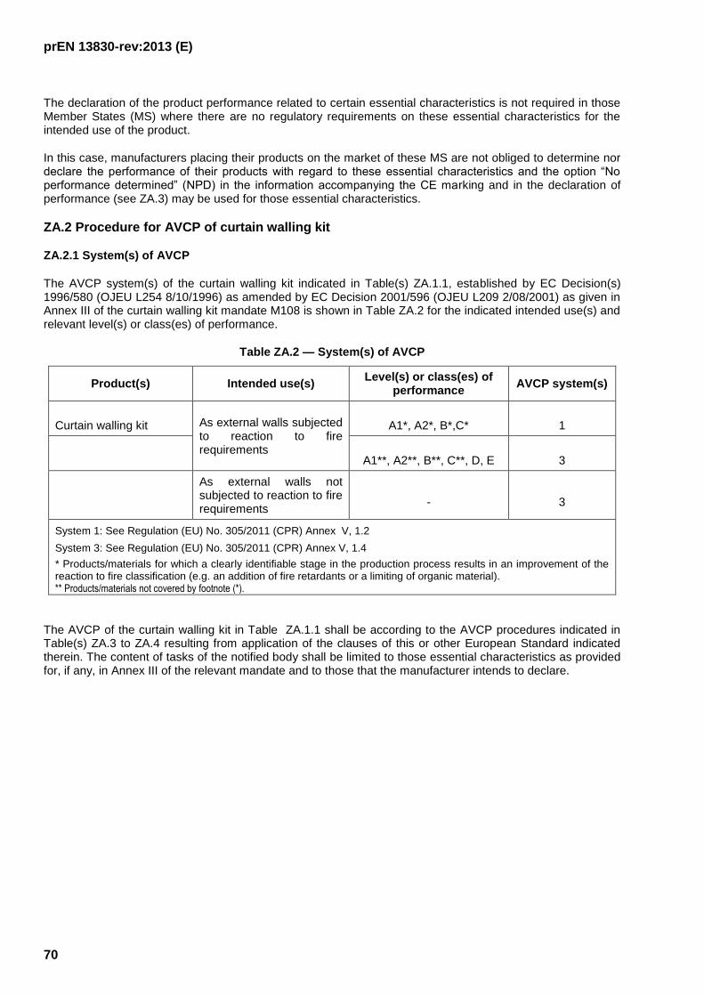
prEN 13830-rev:2013 (E)
70
The declaration of the product performance related to certain essential characteristics is not required in those Member States (MS) where there are no regulatory requirements on these essential characteristics for the intended use of the product.
In this case, manufacturers placing their products on the market of these MS are not obliged to determine nor declare the performance of their products with regard to these essential characteristics and the option “No performance determined” (NPD) in the information accompanying the CE marking and in the declaration of performance (see ZA.3) may be used for those essential characteristics.
ZA.2 Procedure for AVCP of curtain walling kit
ZA.2.1 System(s) of AVCP
The AVCP system(s) of the curtain walling kit indicated in Table(s) ZA.1.1, established by EC Decision(s) 1996/580 (OJEU L254 8/10/1996) as amended by EC Decision 2001/596 (OJEU L209 2/08/2001) as given in Annex III of the curtain walling kit mandate M108 is shown in Table ZA.2 for the indicated intended use(s) and relevant level(s) or class(es) of performance.
Table ZA.2 — System(s) of AVCP
Product(s) Intended use(s) Level(s) or class(es) of
performance AVCP system(s)
Curtain walling kit As external walls subjected
to reaction to fire requirements
A1*, A2*, B*,C*
1
A1**, A2**, B**, C**, D, E
3
As external walls not subjected to reaction to fire requirements
-
3
System 1: See Regulation (EU) No. 305/2011 (CPR) Annex V, 1.2
System 3: See Regulation (EU) No. 305/2011 (CPR) Annex V, 1.4
* Products/materials for which a clearly identifiable stage in the production process results in an improvement of the reaction to fire classification (e.g. an addition of fire retardants or a limiting of organic material). ** Products/materials not covered by footnote (*).
The AVCP of the curtain walling kit in Table ZA.1.1 shall be according to the AVCP procedures indicated in Table(s) ZA.3 to ZA.4 resulting from application of the clauses of this or other European Standard indicated therein. The content of tasks of the notified body shall be limited to those essential characteristics as provided for, if any, in Annex III of the relevant mandate and to those that the manufacturer intends to declare.

prEN 13830-rev:2013 (E)
71
Table ZA.3 — Assignment of evaluation of conformity tasks for type testing for curtain walling under system 1
Tasks Content of the task AVCP clauses
to apply
Tasks for the
manufacturer
Factory production
control (FPC)
Parameters related to essential characteristics of Table ZA.1 relevant for the intended use
which are declared
6.3
Further testing of
samples taken at factory according to the
prescribed test plan
Essential characteristics of Table ZA.1 relevant for the intended use which are declared
6.3.6
Tasks for the notified product
certification body
Determination of the
product type on the basis of type testing
(including sampling), type calculation,
tabulated values or descriptive
documentation of the product
Reaction to fire of components
Fire resistance
Fire propagation (to upper levels)
Resistance to its own load
Wind load resistance
Resistance to snow load (only for elements subjected to snow load)
Impact resistance
Resistance to live horizontal loads at sill level
Seismic resistance
Thermal shock resistance
6.2
Initial inspection of
manufacturing plant and of FPC
Parameters related to essential characteristics of Table ZA.1, relevant for the intended use
which are declared, namely
Reaction to fire of components
Fire resistance
Fire propagation (to upper levels)
Resistance to its own load
Wind load resistance
Resistance to snow load (only for elements subjected to snow load)
Impact resistance
Resistance to live horizontal loads at sill level
Seismic resistance
Thermal shock resistance
Documentation of the FPC.
6.3.4
Continuous surveillance,
assessment and evaluation of FPC
Parameters related to essential characteristics of Table ZA.1, relevant for the intended use
which are declared, namely reaction to fire of components. Documentation of FPC
6.3.5

prEN 13830-rev:2013 (E)
72
Table ZA.4 — Assignment of evaluation of conformity tasks for type testing for curtain walling under system 3
Tasks Content of the task
Evaluation of
conformity
clauses to apply
Tasks for the
manufacturer
Factory production control
(FPC)
Parameters related to essential
characteristics of Table ZA.1 relevant for
the intended use which are declared
6.3
Tasks for a notified
testing laboratory
Determination of the
product-type on the basis of
type testing (based on
sampling carried out by the
manufacturer), type
calculation, tabulated values
or descriptive
documentation of the
product
Fire resistance
Fire propagation (to upper levels)
Resistance to its own load
Wind load resistance
Resistance to snow load (only for
elements subjected to snow load)
Impact resistance
Resistance to live horizontal loads at sill
level
Seismic resistance
Thermal shock resistance
6.2
ZA.2.2.2 Declaration of performance (DoP)
ZA.2.2.1 General
The manufacturer draws up the DoP and affixes the CE marking on the basis of the different AVCP systems set out in Annex V of the Regulation (EU) No 305/2011:
In case of products under system 1
the factory production control and further testing of samples taken at the factory according to the prescribed test plan, carried out by the manufacturer; and
the certificate of constancy of performance issued by the notified product certification body on the basis of determination of the product type on the basis of type testing (including sampling), type calculation, tabulated values or descriptive documentation of the product; initial inspection of the manufacturing plant and of factory production control and continuous surveillance, assessment and evaluation of factory production control.
In case of products under system 3
the factory production control carried out by the manufacturer; and
the determination of the product-type on the basis of type testing (based on sampling carried out by the manufacturer), type calculation, tabulated values or descriptive documentation of the product, carried out by the notified testing laboratory.
ZA.2.2.2 Content
The model of the DoP is provided in Annex III of the Regulation (EU) No 305/2011.
prEN 13830-rev:2013 (E)
73
According to this Regulation, the DoP shall contain, in particular, the following information:
the reference of the product-type for which the declaration of performance has been drawn up;
the AVCP system or systems of the construction product, as set out in Annex V of the CPR;
the reference number and date of issue of the harmonised standard which has been used for the assessment of each essential characteristic;
where applicable, the reference number of the Specific Technical Documentation used and the requirements with which the manufacturer claims the product complies.
The DoP shall in addition contain:
a) the intended use or uses for the construction product, in accordance with the applicable harmonised technical specification;
b) the list of essential characteristics, as determined in the harmonised technical specification for the declared intended use or uses;
c) the performance of at least one of the essential characteristics of the construction product, relevant for the declared intended use or uses;
d) where applicable, the performance of the construction product, by levels or classes, or in a description, if necessary based on a calculation in relation to its essential characteristics determined in accordance with the Commission determination regarding those essential characteristics for which the manufacturer shall declare the performance of the product when it is placed on the market or the Commission determination regarding threshold levels for the performance in relation to the essential characteristics to be declared.
e) the performance of those essential characteristics of the construction product which are related to the intended use or uses, taking into consideration the provisions in relation to the intended use or uses where the manufacturer intends the product to be made available on the market;
f) for the listed essential characteristics for which no performance is declared, the letters "NPD" (No Performance Determined).
Regarding the supply of the DoP, article 7 of the Regulation (EU) No 305/2011 applies.
The information referred to in Article 31 or, as the case may be, in Article 33 of Regulation (EC) No 1907/2006, (REACH) shall be provided together with the DoP.

prEN 13830-rev:2013 (E)
74
ZA.2.2.3 Example of DoP
The following gives an example of a filled-in DoP for curtain walling kit
DECLARATION OF PERFORMANCE 00001-ABC-789123
1. Unique identification code of the product-type:
Curtain walling kit as external wall
00001-ABC-789123
2 Type, batch or serial number or any other element allowing identification of the construction product as required under Article 11(4):
Curtain walling kit type XX
00001-ABC-789123
3. Intended use or uses of the construction product, in accordance with the applicable harmonised technical specification, as foreseen by the manufacturer:
Curtain walling kit as external wall for office buildings.
4. Name, registered trade name or registered trade mark and contact address of the manufacturer as required under Article 11(5): AnyCo SA, PO Box 21
B-1050 Brussels, Belgium Tel. +32987654321 Fax: +32123456789
Email: [email protected]
5. Where applicable, name and contact address of the authorised representative whose mandate covers the tasks specified in Article 12(2):
Anyone Ltd Flower Str. 24
West Hamfordshire UK-589645 United Kingdom
Tel. +44987654321 Fax: +44123456789
e-mail: [email protected]
6. System or systems of assessment and verification of constancy of performance of the construction product as set out in CPR, Annex V:
System 3
7. In case of the declaration of performance concerning a construction product covered by a harmonised standard: Notified testing laboratory “Curtain walling Test Lab ABC” and No. 5678 performed the determination of the product-type on the basis of type testing (based on sampling carried out by the manufacturer), type calculation, tabulated values or descriptive documentation of the product, under system 3 and issued test/calculation reports
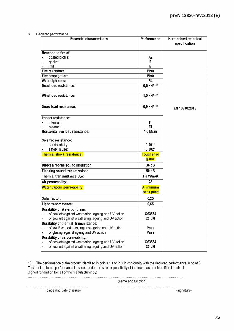
prEN 13830-rev:2013 (E)
75
8. Declared performance
Essential characteristics Performance Harmonised technical specification
Reaction to fire of: - coated profile: - gasket: - infill:
A2 E B
EN 13830:2013
Fire resistance:
EI90
Fire propagation:
EI90
Watertightness: R4
Dead load resistance: 0,6 kN/m2
Wind load resistance: 1,0 kN/m2
Snow load resistance: 0,9 kN/m2
Impact resistance: - internal: - external:
I1 E1
Horizontal live load resistance: 1,0 kN/m
Seismic resistance: - serviceability: - safety in use:
0,001° 0,002°
Thermal shock resistance: Toughened glass
Direct airborne sound insulation:
36 dB
Flanking sound transmission:
50 dB
Thermal transmittance UCW:
1,6 W/m2K
Air permeability:
A3
Water vapour permeability: Aluminium back pane
Solar factor: 0,25
Light transmittance:
0,55
Durability of Watertightness: - of gaskets against weathering, ageing and UV action: - of sealant against weathering, ageing and UV action:
G63554 25 LM
Durability of thermal transmittance: - of low E coated glass against ageing and UV action: - of glazing against ageing and UV action:
Pass Pass
Durability of air permeability: - of gaskets against weathering, ageing and UV action: - of sealant against weathering, ageing and UV action:
G63554 25 LM
10. The performance of the product identified in points 1 and 2 is in conformity with the declared performance in point 8. This declaration of performance is issued under the sole responsibility of the manufacturer identified in point 4. Signed for and on behalf of the manufacturer by: ………………………………………………………………………………………………………………………………
(name and function) …………………………………..…………… …………………………………..……………
(place and date of issue) (signature)

prEN 13830-rev:2013 (E)
76
ZA.3 CE Marking and labelling
The CE marking symbol shall be in accordance with the general principles set out in Article 30 of Regulation (EC) No 765/2008 and shall be affixed visibly, legibly and indelibly:
to the curtain walling kit
or
to a label attached to it.
Where this is not possible or not warranted on account of the nature of the product, it shall be affixed:
to the packaging
or
to the accompanying documents.
The CE marking shall be followed by:
the last two digits of the year in which it was first affixed;
the name and the registered address of the manufacturer, or the identifying mark allowing identification of the name and address of the manufacturer easily and without any ambiguity;
the unique identification code of the product-type;
the reference number of the declaration of performance;
the level or class of the performance declared;
the dated reference to the harmonised technical specification applied;
the identification number of the notified body;
the intended use as laid down in the harmonised technical specification applied.
The CE marking shall be affixed before the construction product is placed on the market. It may be followed by a pictogram or any other mark notably indicating a special risk or use.
Figures ZA.1 to ZA.2 give examples of the information related to products subject to AVCP under each of the different systems to be given on the accompanying documents.

prEN 13830-rev:2013 (E)
77
0124
CE marking, consisting of the “CE”-symbol
Identification number(s) of the notified test
laboratory(ies)
AnyCo Ltd, PO Box 21, B-1050, Brussels, Belgium
14
00001-ABC-789123
Name and the registered address of the
manufacturer, or identifying mark
Last two digits of the year in which the
marking was first affixed
Reference number of the DoP
EN 13830:2014
00001-ABC-789123
Curtain walling kit as external walls
Reaction to fire of:
- coated profile:
- gasket:
- infill:
Fire resistance:
Fire propagation:
Watertightness:
Dead load resistance:
Wind load resistance:
Snow load resistance:
Impact resistance:
- Internal:
- External:
Horizontal live load resistance:
Seismic resistance
- Serviceability:
- Safety in use:
Thermal shock resistance:
Direct airborne sound insulation:
Flanking sound transmission:
Thermal transmittance:
Air permeability:
Water vapour permeability:
Solar factor:
Light transmittance:
Durability of Watertightness:
- of gaskets against weathering, ageing and UV action:
- of sealant against weathering, ageing and UV action:
Durability of thermal transmittance
- of low E coated glass against ageing and UV action:
- of glazing against ageing and UV action:
Durability of air permeability
- of gaskets against weathering, ageing and UV action:
- of sealant against weathering, ageing and UV action:
A2
E
B
EI90
EI90
R4
0,6 kN/m2
1,0 kN/m2
0,9 kN/m2
I1
E1
1,0 kN/m
0,001°
0,002°
Toughened glass
36 dB
50 dB
1,6 W/m2K
A3
Aluminium back pane
0,25
0,55
G63554
25 LM
Pass
Pass
G63554
25 LM
No. of European standard applied, as
referenced in OJEU
Unique identification code of the product-type
Intended use of the product as laid down in
the European standard applied
Level or class of the performance declared
Figure ZA.1 — Example CE marking information of products under AVCP system 3

prEN 13830-rev:2013 (E)
78
0123
CE marking, consisting of the “CE”-
symbol
Identification number(s) of the notified
test laboratory(ies) and of the notified
product certification body
AnyCo Ltd, PO Box 21, B-1050, Brussels, Belgium
14
00001-ABC-789124
Name and the registered address of
the manufacturer, or identifying mark
Last two digits of the year in which the
marking was first affixed
Reference number of the DoP
EN 13830:2014
00001-ABC-789124
Curtain walling kit as external walls
Reaction to fire of:
- coated profile:
- infill:
Fire resistance:
Fire propagation:
Watertightness:
Dead load resistance:
Wind load resistance:
Snow load resistance:
Impact resistance:
- Internal:
- External:
Horizontal live load resistance:
Seismic resistance
- Serviceability:
- Safety in use:
Thermal shock resistance:
Direct airborne sound insulation:
Flanking sound transmission:
Thermal transmittance:
Air permeability:
Water vapour permeability:
Solar factor:
Light transmittance:
Durability of Watertightness:
- of gaskets against weathering, ageing and UV action:
- of sealant against weathering, ageing and UV action:
Durability of thermal transmittance
- of low E coated glass against ageing and UV action:
- of glazing against ageing and UV action:
Durability of air permeability
- of gaskets against weathering, ageing and UV action:
- of sealant against weathering, ageing and UV action:
A2
B
EI90
EI90
R4
0,6 kN/m2
1,0 kN/m2
0,9 kN/m2
I1
E1
1,0 kN/m
0,001°
0,002°
Toughened glass
36 dB
50 dB
1,6 W/m2K
A3
Aluminium back pane
0,25
0,55
G63554
25 LM
Pass
Pass
G63554
25 LM
No. of European standard applied, as
referenced in OJEU
Unique identification code of the
product-type
Intended use of the product as laid
down in the European standard applied
Level or class of the performance
declared
Figure ZA.2 — Example CE marking information of products under AVCP system 1

prEN 13830-rev:2013 (E)
79
Bibliography
[1] EN 1993-1-1, Eurocode 3: Design of steel structures - Part 1-1: General rules and rules for buildings
[2] EN 1995-1-1, Eurocode 5: Design of timber structures - Part 1-1: General - Common rules and rules for buildings
[3] EN 1997, Eurocode 7: Geotechnical design
[4] EN 1999-1-1, Eurocode 9: Design of aluminium structures - Part 1-1: General structural rules
[5] ENV 13050, Curtain walling - Watertightness - Laboratory test under dynamic condition of air pressure and water spray
[6] EN 13051, Curtain walling - Watertightness – Site test
[7] EN ISO 10140-1, Acoustics - Laboratory measurement of sound insulation of building elements - Part 1: Application rules for specific products
[8] EN ISO 10140-4, Acoustics - Laboratory measurement of sound insulation of building elements - Part 4: Measurement procedures and Requirements
[9] EN ISO 10140-5, Acoustics - Laboratory measurement of sound insulation of building elements - Part 5:
Requirements for test facilities and equipment [10] EN ISO 13788, Hygrothermal performance of building components and building elements - Internal
surface temperature to avoid critical surface humidity and interstitial condensation - Calculation methods
[11] AAMA 501.4-00 (Revised 7/18/01) Recommended Static Test Method For Evaluating Curtain Wall And Storefront Systems Subjected To Seismic And Wind Induced Interstorey Drifts