
MVAJ053
38
| AUTOMATION GRID MVAJ 05, 10, 20 Tripping & Control Relays Technical Manual R8141D
-
Upload
yusof-basri -
Category
Documents
-
view
194 -
download
3
Transcript of MVAJ053
| AUTOMATION
GRID
MVAJ 05, 10, 20 Tripping & Control Relays
Technical Manual
R8141D
Note: The technical manual for this device gives instructions for its installation, commissioning, and operation. However, the manual cannot cover all conceivable circumstances or include detailed information on all topics. In the event of questions or specific problems, do not take any action without proper authorization. Contact the appropriate Alstom Grid technical sales office and request the necessary information.
Any agreements, commitments, and legal relationships and any obligations on the part of Alstom Grid including settlements of warranties, result solely from the applicable purchase contract, which is not affected by the contents of the technical manual.
This device MUST NOT be modified. If any modification is made without the express permission of Alstom Grid, it will invalidate the warranty, and may render the product unsafe.
The Alstom Grid logo and any alternative version thereof are trademarks and service marks of Alstom Grid.
All trade names or trademarks mentioned herein whether registered or not, are the property of their owners.
This manual is provided for informational use only and is subject to change without notice.
© 2010, Alstom Grid. All rights reserved.
Technical Manual R8141D Types MVAJ 05, 10, 20
Page 1/34
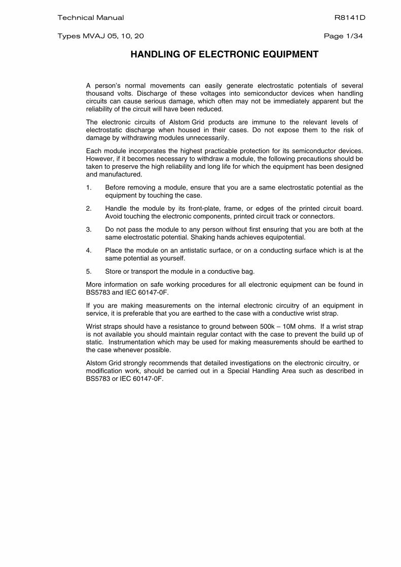
HANDLING OF ELECTRONIC EQUIPMENT
A person’s normal movements can easily generate electrostatic potentials of several thousand volts. Discharge of these voltages into semiconductor devices when handling circuits can cause serious damage, which often may not be immediately apparent but the reliability of the circuit will have been reduced.
The electronic circuits of Alstom Grid products are immune to the relevant levels of electrostatic discharge when housed in their cases. Do not expose them to the risk of damage by withdrawing modules unnecessarily.
Each module incorporates the highest practicable protection for its semiconductor devices. However, if it becomes necessary to withdraw a module, the following precautions should be taken to preserve the high reliability and long life for which the equipment has been designed and manufactured.
1. Before removing a module, ensure that you are a same electrostatic potential as the equipment by touching the case.
2. Handle the module by its front-plate, frame, or edges of the printed circuit board. Avoid touching the electronic components, printed circuit track or connectors.
3. Do not pass the module to any person without first ensuring that you are both at the same electrostatic potential. Shaking hands achieves equipotential.
4. Place the module on an antistatic surface, or on a conducting surface which is at the same potential as yourself.
5. Store or transport the module in a conductive bag.
More information on safe working procedures for all electronic equipment can be found in BS5783 and IEC 60147-0F.
If you are making measurements on the internal electronic circuitry of an equipment in service, it is preferable that you are earthed to the case with a conductive wrist strap.
Wrist straps should have a resistance to ground between 500k – 10M ohms. If a wrist strap is not available you should maintain regular contact with the case to prevent the build up of static. Instrumentation which may be used for making measurements should be earthed to the case whenever possible.
Alstom Grid strongly recommends that detailed investigations on the electronic circuitry, or modification work, should be carried out in a Special Handling Area such as described in BS5783 or IEC 60147-0F.

R8141D Technical Manual Page 2/34
Types MVAJ 05, 10, 20
Technical Manual R8141D Types MVAJ 05, 10, 20
Page 3/34
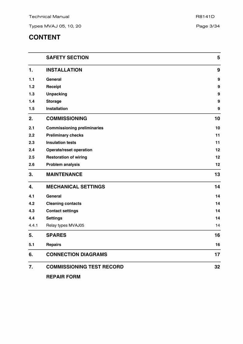
CONTENT
SAFETY SECTION 5
1. INSTALLATION 9
1.1 General 9 1.2 Receipt 9 1.3 Unpacking 9 1.4 Storage 9 1.5 Installation 9
2. COMMISSIONING 10
2.1 Commissioning preliminaries 10 2.2 Preliminary checks 11 2.3 Insulation tests 11 2.4 Operate/reset operation 12 2.5 Restoration of wiring 12 2.6 Problem analysis 12
3. MAINTENANCE 13
4. MECHANICAL SETTINGS 14
4.1 General 14 4.2 Cleaning contacts 14 4.3 Contact settings 14 4.4 Settings 14 4.4.1 Relay types MVAJ05 14
5. SPARES 16
5.1 Repairs 16
6. CONNECTION DIAGRAMS 17
7. COMMISSIONING TEST RECORD 32
REPAIR FORM

R8141D Technical Manual Page 4/34
Types MVAJ 05, 10, 20
Technical Manual R8141D Types MVAJ 05, 10, 20
Page 5/34
1. SAFETY SECTION
This Safety Section should be read before commencing any work on the equipment.
1.1 Health and safety
The information in the Safety Section of the product documentation is intended to ensure that products are properly installed and handled in order to maintain them in a safe condition. It is assumed that everyone who will be associated with the equipment will be familiar with the contents of the Safety Section.
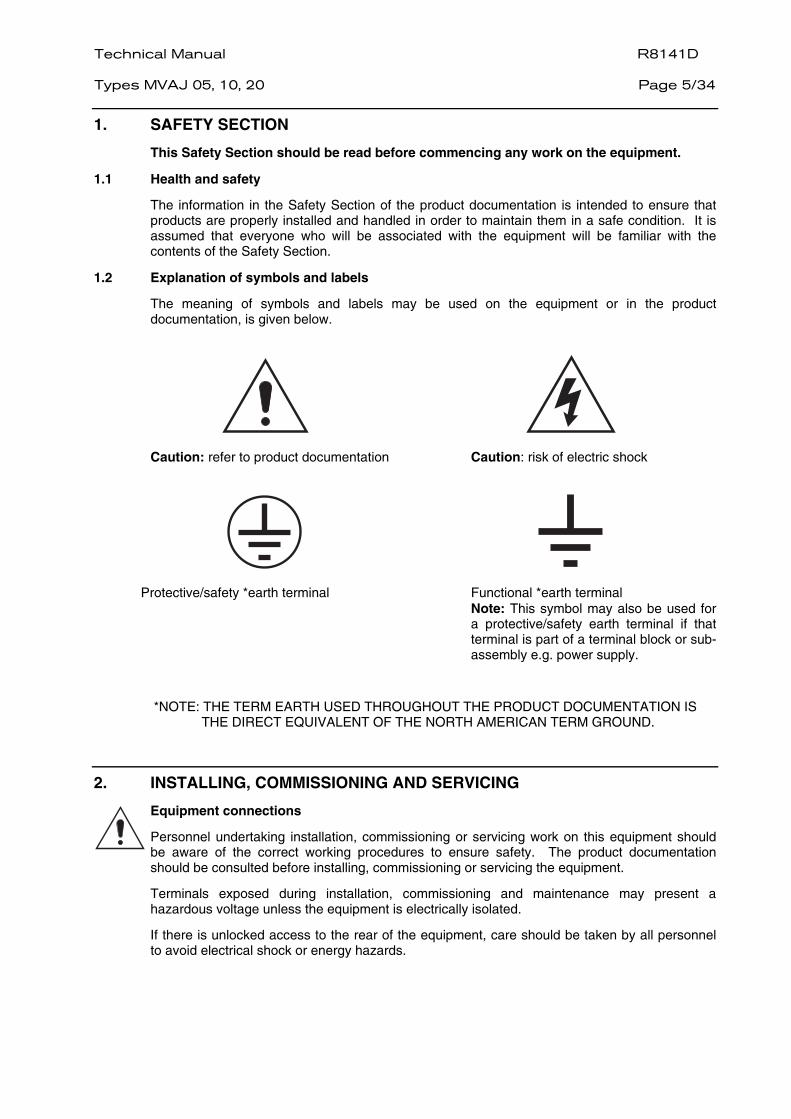
1.2 Explanation of symbols and labels
The meaning of symbols and labels may be used on the equipment or in the product documentation, is given below.
Caution: refer to product documentation Caution: risk of electric shock
Protective/safety *earth terminal Functional *earth terminal
Note: This symbol may also be used for a protective/safety earth terminal if that terminal is part of a terminal block or sub-assembly e.g. power supply.
*NOTE: THE TERM EARTH USED THROUGHOUT THE PRODUCT DOCUMENTATION IS THE DIRECT EQUIVALENT OF THE NORTH AMERICAN TERM GROUND.
2. INSTALLING, COMMISSIONING AND SERVICING
Equipment connections
Personnel undertaking installation, commissioning or servicing work on this equipment should be aware of the correct working procedures to ensure safety. The product documentation should be consulted before installing, commissioning or servicing the equipment.
Terminals exposed during installation, commissioning and maintenance may present a hazardous voltage unless the equipment is electrically isolated.
If there is unlocked access to the rear of the equipment, care should be taken by all personnel to avoid electrical shock or energy hazards.
R8141D Technical Manual Page 6/34
Types MVAJ 05, 10, 20
Voltage and current connections should be made using insulated crimp terminations to ensure that terminal block insulation requirements are maintained for safety. To ensure that wires are correctly terminated, the correct crimp terminal and tool for the wire size should be used.
Before energising the equipment it must be earthed using the protective earth terminal, or the appropriate termination of the supply plug in the case of plug connected equipment. Omitting or disconnecting the equipment earth may cause a safety hazard.
The recommended minimum earth wire size is 2.5mm2, unless otherwise stated in the technical data section of the product documentation.
Before energising the equipment, the following should be checked:
− Voltage rating and polarity;
− CT circuit rating and integrity of connections;
− Protective fuse rating;
− Integrity of earth connection (where applicable)
− Remove front plate plastic film protection
− Remove insulating strip from battery compartment
3. EQUIPMENT OPERATING CONDITIONS
The equipment should be operated within the specified electrical and environmental limits.
3.1 Current transformer circuits
Do not open the secondary circuit of a live CT since the high level voltage produced may be lethal to personnel and could damage insulation.
3.2 External resistors
Where external resistors are fitted to relays, these may present a risk of electric shock or burns, if touched.
3.3 Battery replacement
Where internal batteries are fitted they should be replaced with the recommended type and be installed with the correct polarity, to avoid possible damage to the equipment.
3.4 Insulation and dielectric strength testing
Insulation testing may leave capacitors charged up to a hazardous voltage. At the end of each part of the test, the voltage should be gradually reduced to zero, to discharge capacitors, before the test leads are disconnected.
3.5 Insertion of modules and pcb cards
These must not be inserted into or withdrawn from equipment whist it is energised since this may result in damage.
3.6 Fibre optic communication
Where fibre optic communication devices are fitted, these should not be viewed directly. Optical power meters should be used to determine the operation or signal level of the device.
Technical Manual R8141D Types MVAJ 05, 10, 20
Page 7/34
4. OLDER PRODUCTS
Electrical adjustments
Equipments which require direct physical adjustments to their operating mechanism to change current or voltage settings, should have the electrical power removed before making the change, to avoid any risk of electrical shock.
Mechanical adjustments
The electrical power to the relay contacts should be removed before checking any mechanical settings, to avoid any risk of electric shock.
Draw out case relays
Removal of the cover on equipment incorporating electromechanical operating elements, may expose hazardous live parts such as relay contacts.
Insertion and withdrawal of extender cards
When using an extender card, this should not be inserted or withdrawn from the equipment whilst it is energised. This is to avoid possible shock or damage hazards. Hazardous live voltages may be accessible on the extender card.
Insertion and withdrawal of heavy current test plugs
When using a heavy current test plug, CT shorting links must be in place before insertion or removal, to avoid potentially lethal voltages.
5. DECOMMISSIONING AND DISPOSAL
Decommissioning: The auxiliary supply circuit in the relay may include capacitors across the supply or to earth. To avoid electric shock or energy hazards, after completely isolating the supplies to the relay (both poles of any dc supply), the capacitors should be safely discharged via the external terminals prior to decommissioning.
Disposal: It is recommended that incineration and disposal to water courses is
avoided. The product should be disposed of in a safe manner. Any products containing batteries should have them removed before disposal, taking precautions to avoid short circuits. Particular regulations within the country of operation, may apply to the disposal of lithium batteries.
R8141D Technical Manual Page 8/34
Types MVAJ 05, 10, 20
6. TECHNICAL SPECIFICATIONS
Protective fuse rating
The recommended maximum rating of the external protective fuse for this equipment is 16A, Red Spot type or equivalent, unless otherwise stated in the technical data section of the product documentation.
Insulation class: IEC 601010-1 : 1990/A2 : 2001 Class I EN 61010-1: 2001 Class I
This equipment requires a protective (safety) earth connection to ensure user safety.
Insulation Category (Overvoltage):
IEC 601010-1 : 1990/A2 : 1995 Category III EN 61010-1: 2001 Category III
Distribution level, fixed insulation. Equipment in this category is qualification tested at 5kV peak, 1.2/50µs, 500Ω, 0.5J, between all supply circuits and earth and also between independent circuits.
Environment: IEC 601010-1 : 1990/A2 : 1995 Pollution degree 2
EN 61010-1: 2001 Pollution degree 2
Compliance is demonstrated by reference to generic safety standards.
Product Safety:
72/23/EEC
EN 61010-1: 2001 EN 60950-1: 2002
Compliance with the European Commission Low Voltage Directive.
Compliance is demonstrated by reference to generic safety standards.
Technical Manual R8141D Types MVAJ 05, 10, 20
Page 9/34
1. INSTALLATION
1.1 General
Protective relays, although generally of robust construction, require careful treatment prior to installation and a wise selection of site. By observing a few simple rules the possibility of premature failure is eliminated and a high degree of performance can be expected.
The safety section should be read before any work takes place and should be referred to throughout. Special care should be taken to adhere to suitable electro-static discharge precautions.
1.2 Receipt
The relays are either despatched individually or as part of a panel/rack mounted assembly in cartons specifically designed to protect them from damage.
Relays should be examined immediately they are received to ensure that no damage has been sustained in transit. If damage due to rough handling is evident ,a claim should be made to the transport company concerned immediately and Alstom Grid should be promptly notified. Relays which are supplied un mounted and not intended for immediate installation should be returned to their protective polythene bags.
1.3 Unpacking
Care must be taken when unpacking and installing the relays so that none of the parts are damaged or their settings altered and must only be handled by skilled persons.
Relays should be examined for any wedges, clamps, or rubber bands necessary to secure moving parts to prevent damage during transit and these should be removed after installation and before commissioning.
Relays which have been removed from their cases should not be left in situations where they are exposed to dust or damp. This particularly applies to installations which are being carried out at the same time as construction work.
1.4 Storage
If relays are not installed immediately upon receipt they should be stored in a place free from dust and moisture in their original cartons and where de-humidifier bags have been included in the packing they should be retained. The action of the de-humidifier crystals will be impaired if the bag has been exposed to ambient conditions and may be restored by gently heating the bag for about an hour, prior to replacing it in the carton.
Dust which collects on a carton may, on subsequent unpacking, find its way into the relay; in damp conditions the carton and packing may become impregnated with moisture and the de-humidifying agent will lose its efficiency.
The storage temperature range is –40°C to +70°C.
1.5 Installation
The installation should be clean, dry and reasonably free from dust and excessive vibration. The site should preferably be well illuminated to facilitate inspection.
An outline diagram is normally supplied showing panel cut-outs and hole centres. For individually mounted relays these dimensions will also be found in publication R6141.
Publication R7012, Parts Catalogue and Assembly Instructions, will be useful when individual relays are to be assembled as a composite rack or panel mounted assembly.
Publication R6001 is a leaflet on the modular integrated draw out system of protective relays.
Publication R6014 is a list of recommended suppliers for the pre-insulated connectors.
R8141D Technical Manual Page 10/34
Types MVAJ 05, 10, 20
2. COMMISSIONING
2.1 Commissioning preliminaries
2.1.1 Electrostatic discharge (ESD)
The relay uses components which are sensitive to electrostatic discharges. Whenhandling the withdrawn module, care should be taken to avoid contact withcomponents and electrical connections. When removed from its case for storagethe module should be placed in an electrically conducting anti-static bag.
2.1.2 Inspection
Carefully examine the module and case to see that no damage has occurredduring transit.
Check that the relay serial number on the module, case and cover are identical,and also check that the rating information is correct for the system.
2.1.3 Wiring
WARNING:
EXPOSED TERMINALS MAY PRESENT A HAZARDOUS VOLTAGE UNLESSEQUIPMENT IS ELECTRICALLY ISOLATED.
Check that the external wiring is correct to the relevant relay diagram and/or scheme diagram. It is especially important that DC supplies are wired with thecorrect polarity. The relay external connection diagram number is given on therating label inside the case.
2.1.4 External links
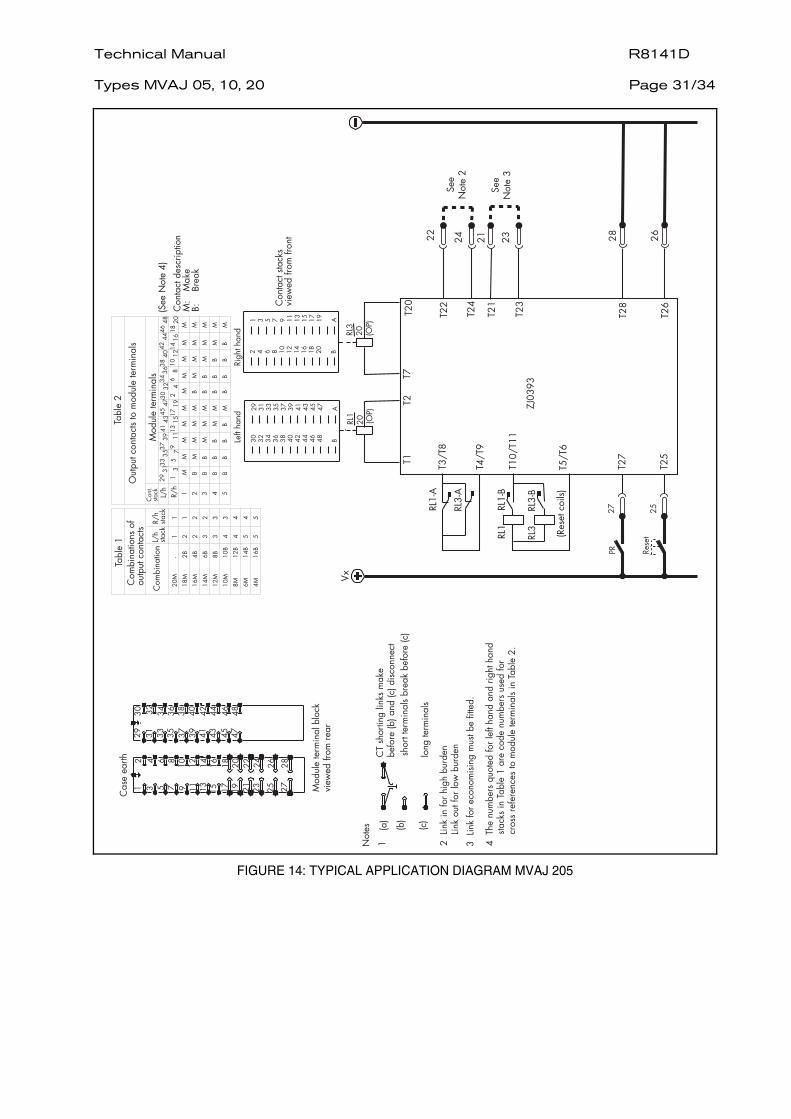
There are two external links as detailed in tables 1 and 2.
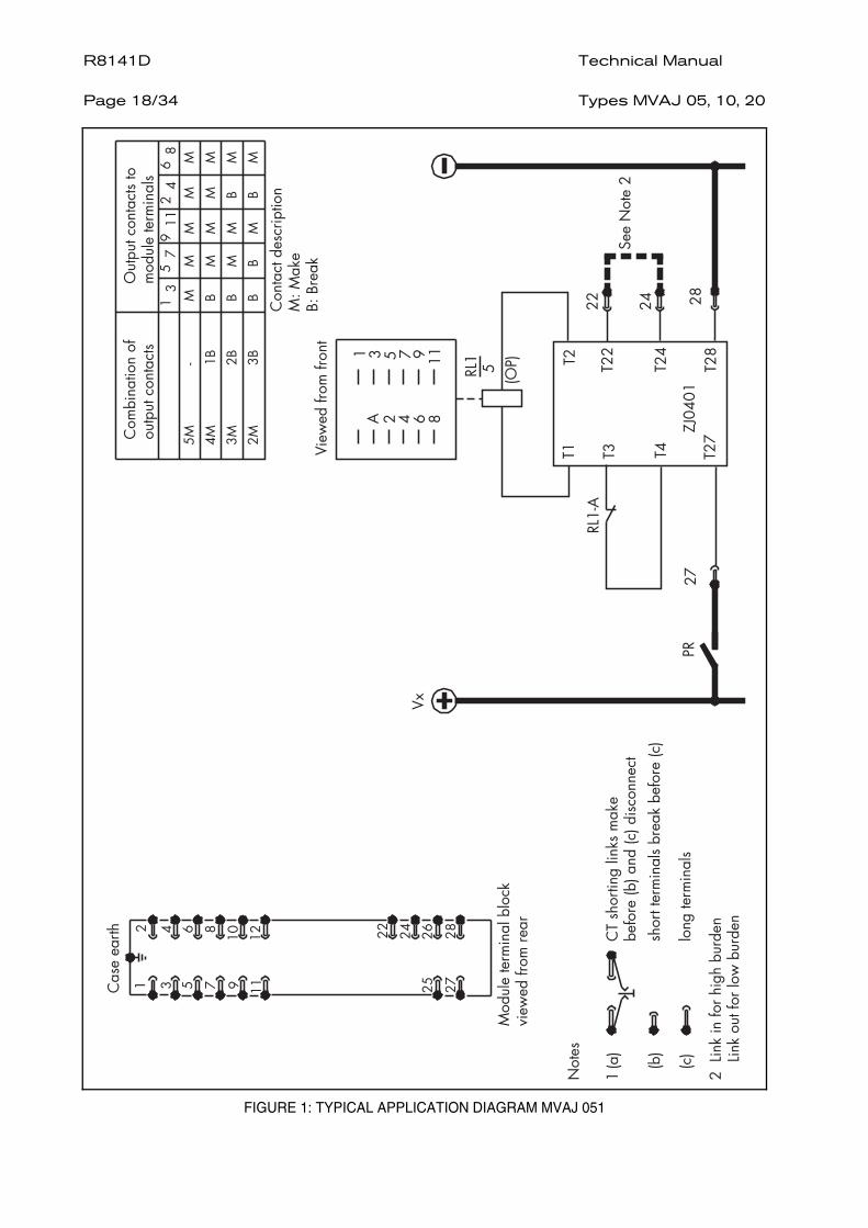
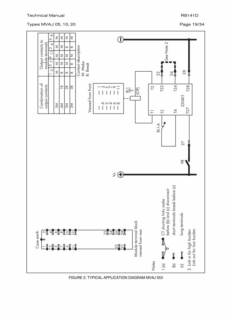
All trip relays are supplied as high burden. With the exception of MVAJ102, 202,they may be converted to low burden by removing the link between case terminals 22 and 24.
Relay type Feature Link in Link out
MVAJ 051, 053, 054, 055 Burden Cut-off
High Instantaneous
Low Instantaneous
MVAJ 101, 103, 104, 105 201, 203, 204, 205
Burden Cut-off
High 40-60ms time delayed
Low Instantaneous
MVAJ102, 202 Link not necessary - configured as high burden models
NOTE: At the point at which the relay cut-off occurs the current drawn by the
relayis either reduced to an economised level or is removed entirely (ie. zerowatt cut-off state).
Table 1: Configuration of high/low burden link (terminals 22 to 24)
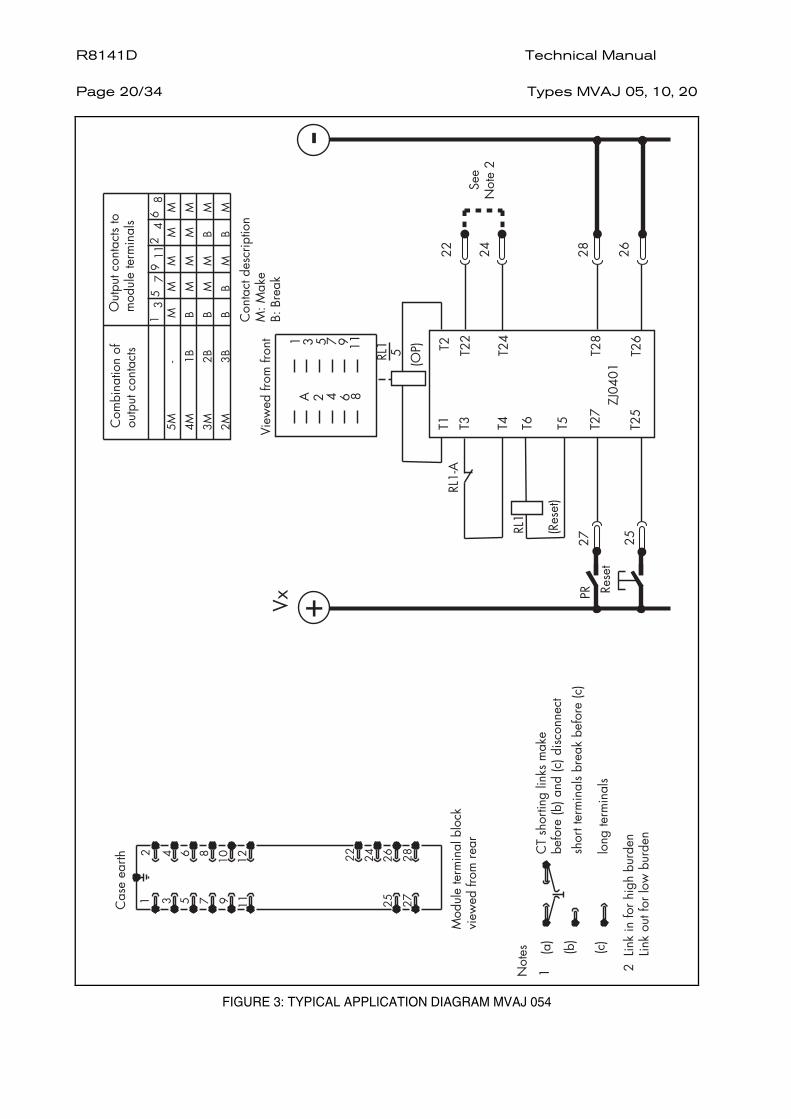
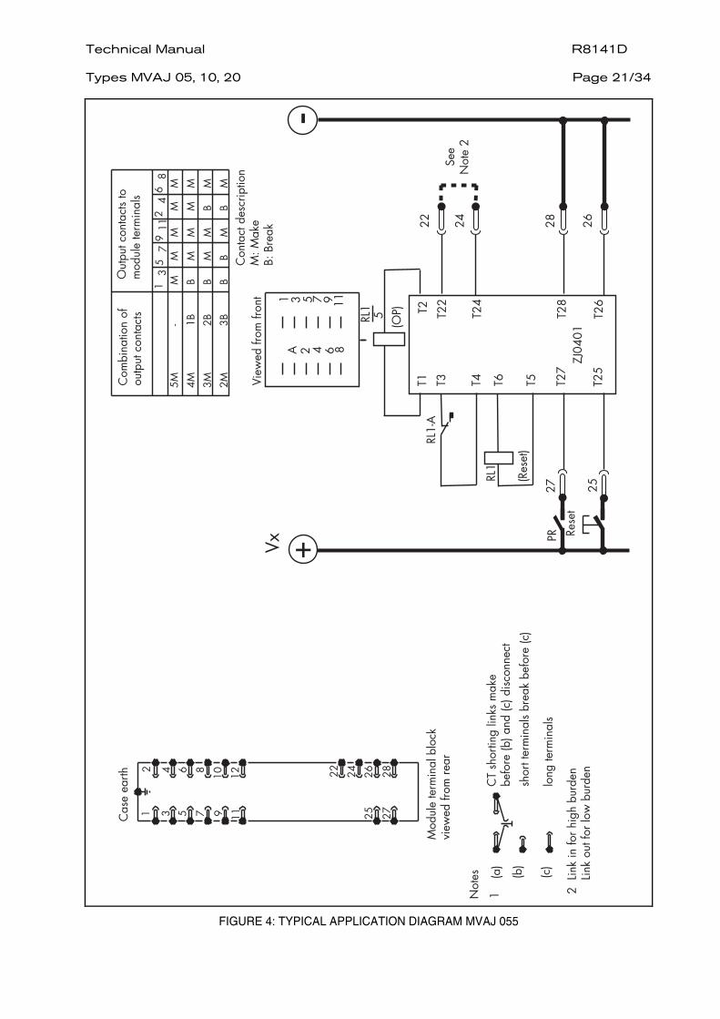
A second link is supplied fitted to selected 10 and 20 contact relays as detailed in Table 2. This link, connected between case terminals 21 and 23 enables a reset inhibitor feature to be introduced into the circuit of 10 and 20 contact electrical reset relays, ensuring that the reset circuit is disabled when the operate circuit is energised. On relay types 104, 105, 204 and 205 this link may be removed if this feature is not required.
NOTE: This link must remain fitted to MVAJ101 and 201 relays to enable the economising circuit.
Technical Manual R8141D Types MVAJ 05, 10, 20
Page 11/34
Relay type Feature Link in Link out
MVAJ 051, 053, 054, 055 101, 102
Link of available
MVAJ 101, 201 Link fitted (relay cut-off to economised state)
MVAJ103, 203 Link not available (relay cut-off to zero watts)
MVAJ104, 105, 204, 205 Cut-off state reset inhibitor
Economised active
Zero watts disablet
Table 2: Configuration of economising/reset inhibit link (terminals 21 to 23)
2.2 Preliminary checks
Before leaving the factory all relays are accurately adjusted, tested and carefullypacked. There should be no need for any re-adjustment on commissioning.
Moving parts are held in position during transit by rubber bands and packing.These should be removed carefully.
2.2.1 To gain access to the relay first loosen the captive cover screws, then carefullyremove the cover from the case.
The module can then be removed from the case by grasping the handles at the topand bottom of the front plate and pulling forwards.
Care must be taken to ensure that mechanical settings of the element are not disturbed.
2.2.2 Carefully remove the rubber band securing the flag mechanism.
2.2.3 Check that the bottom end of the contact operating card has not been dislodgedfrom the slot in the armature extension.
2.2.4 Check that all push-on connections to the PCB are secure.
Check that all the push-on connections to the back of the contacts are secure.
Check that all the push-on connections to terminal block are secure.
2.2.5 Carefully actuate the armature of each unit in turn with a small screwdriver/probe.
On units fitted with hand reset flag indicators, check that the flag is free to fallbefore, or just as, any make contacts close.
2.2.6 Check that the serial number in the cover and the relay case match that of themodule. Replace the module in the case and refit the cover. Make sure that thereset mechanism in the cover is correctly located with respect to the relay elementand that the flag (or mechanism) can be reset.
Check that the armature(s) are in the reset position by pressing the appropriatereset buttons;
2.3 Insulation tests
The relay and its associated wiring may be insulation tested between:
− all electrically isolated circuits
− all circuits and earth
An electronic or brushless insulation tester should be used giving a dc voltage notexceeding 1000V. Accessible terminals of the same circuit should first be strappedtogether. Deliberate circuit earthing links removed for the tests must subsequentlybe replaced.
R8141D Technical Manual Page 12/34
Types MVAJ 05, 10, 20
2.4 Operate/reset operation
WARNING:
EXPOSED TERMINALS MAY PRESENT A HAZARDOUS VOLTAGE UNLESSEQUIPMENT IS ELECTRICALLY ISOLATED.
2.4.1 Self, hand, electrical and hand/electrical reset
1. The operate circuit is terminated to case terminals 27(+), 28(-).
2. The electrical reset circuit is terminated to case terminals 25(+), 26(-).
3. Disconnect external wiring from these terminals to allow application of the test supply.
4. Check operation of operate circuit by energising the relay with 60% of the lower nominal supply voltage. Please note that the supply voltage applied across the relay case terminals should be directly at 60% of the lower nominal supply voltage ( for example LNV= 110 V , so you have to inject 66 V ) and this voltage should not be applied gradually to reach 60% of the lower nominal supply voltage. The relays should switch cleanly with one movement.
5. With the relay set check the continuity of the closed contacts, Contact continuity test should be done by applying 5A current & measuring the voltage across the output contact terminals after that you can check the impedance of the relay.
6. Check the operating time of the relay at 100% lower nominal supply voltage and check the continuity of the closed contacts.
2.4.2 Self-reset 2.5s delayed reset
1. The operate circuit is terminated to case terminals 25(+), 27(+), 28(-).
2. Disconnect external wiring from these terminals to allow application of the test supply.
3. Check operation of operate circuit by energising the relay with 60% of the lower nominal supply voltage. Please note that the supply voltage applied across the relay case terminals should be directly at 60% of the lower nominal supply voltage ( for example LNV= 110 V , so you have to inject 66 V ) and this voltage should not be applied gradually to reach 60% of the lower nominal supply voltage. The relays should switch cleanly with one movement.
4. With the relay set check the continuity of the closed contacts, Contact continuity test should be done by applying 5A current & measuring the voltage across the output contact terminals.
5. Check the operating time of the relay at 100% lower nominal supply voltage and check the continuity of the closed contacts.
6. Check the delayed reset time by energising the relay with full rated supply volts to case terminations 25(+), 27(+), 28(-), then remove energisation from the case termination 27(+). Time the closure of a normally closed contact from this point in time. The reset time shall be between 2 - 2.8s.
2.5 Restoration of wiring
Restore any external wiring connections that may have been disturbed during the above tests.
2.6 Problem analysis
Repeat Section 2.2 with particular attention to the connection of external links.
If the relay is found to be faulty it should be returned to Alstom Grid for repair and recalibration. There are no user serviceable parts inside.

Technical Manual R8141D Types MVAJ 05, 10, 20
Page 13/34
3. MAINTENANCE
Periodic maintenance is not necessary, however routine testing should be carriedout the meet the customer requirements.
Check the relay for operation at 60% lower nominal supply voltage and forcontact wear. If required, the mechanical settings may be checked against thoseshown in Section 4.
R8141D Technical Manual Page 14/34
Types MVAJ 05, 10, 20
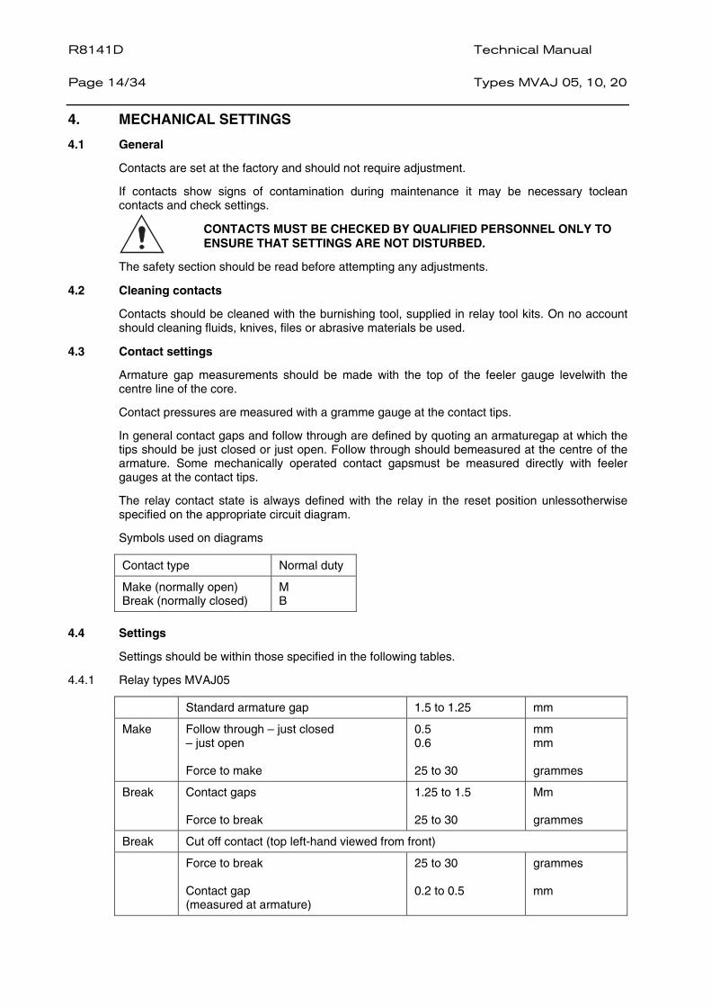
4. MECHANICAL SETTINGS
4.1 General
Contacts are set at the factory and should not require adjustment.
If contacts show signs of contamination during maintenance it may be necessary toclean contacts and check settings.
CONTACTS MUST BE CHECKED BY QUALIFIED PERSONNEL ONLY TO ENSURE THAT SETTINGS ARE NOT DISTURBED.
The safety section should be read before attempting any adjustments.
4.2 Cleaning contacts
Contacts should be cleaned with the burnishing tool, supplied in relay tool kits. On no account should cleaning fluids, knives, files or abrasive materials be used.
4.3 Contact settings
Armature gap measurements should be made with the top of the feeler gauge levelwith the centre line of the core.
Contact pressures are measured with a gramme gauge at the contact tips.
In general contact gaps and follow through are defined by quoting an armaturegap at which the tips should be just closed or just open. Follow through should bemeasured at the centre of the armature. Some mechanically operated contact gapsmust be measured directly with feeler gauges at the contact tips.
The relay contact state is always defined with the relay in the reset position unlessotherwise specified on the appropriate circuit diagram.
Symbols used on diagrams
Contact type Normal duty
Make (normally open) Break (normally closed)
M B
4.4 Settings
Settings should be within those specified in the following tables.
4.4.1 Relay types MVAJ05
Standard armature gap 1.5 to 1.25 mm
Make Follow through – just closed – just open Force to make
0.5 0.6 25 to 30
mm mm grammes
Break Contact gaps Force to break
1.25 to 1.5 25 to 30
Mm grammes
Break Cut off contact (top left-hand viewed from front)
Force to break Contact gap (measured at armature)
25 to 30 0.2 to 0.5
grammes mm
Technical Manual R8141D Types MVAJ 05, 10, 20
Page 15/34
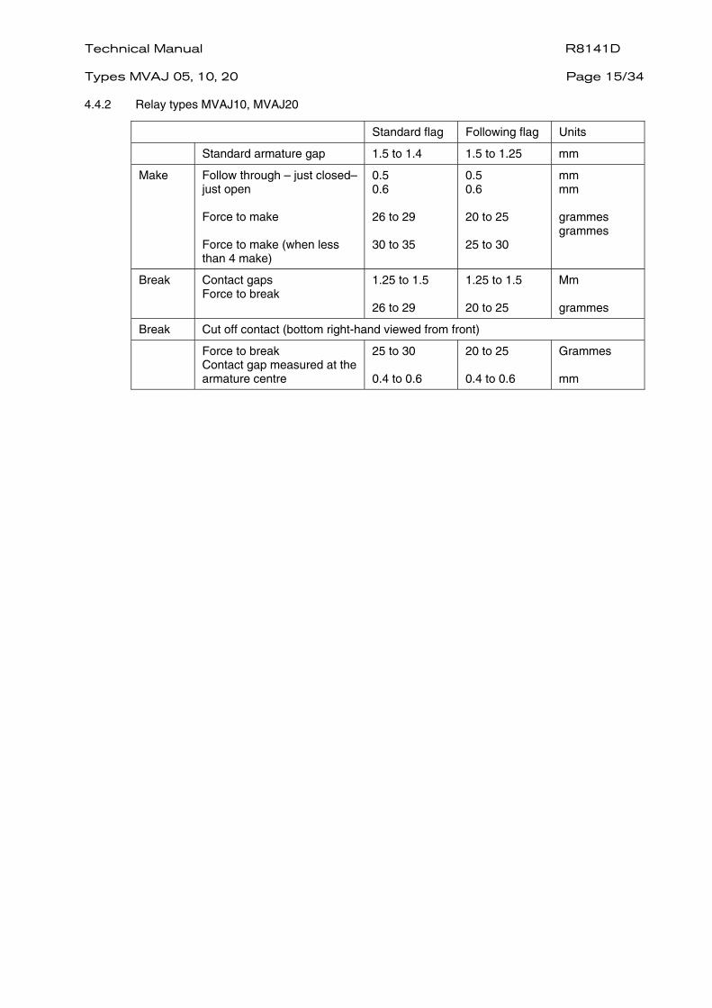
4.4.2 Relay types MVAJ10, MVAJ20
Standard flag Following flag Units
Standard armature gap 1.5 to 1.4 1.5 to 1.25 mm
Make Follow through – just closed– just open Force to make Force to make (when less than 4 make)
0.5 0.6 26 to 29 30 to 35
0.5 0.6 20 to 25 25 to 30
mm mm grammes grammes
Break Contact gaps Force to break
1.25 to 1.5 26 to 29
1.25 to 1.5 20 to 25
Mm grammes
Break Cut off contact (bottom right-hand viewed from front)
Force to break Contact gap measured at the armature centre
25 to 30 0.4 to 0.6
20 to 25 0.4 to 0.6
Grammes mm
R8141D Technical Manual Page 16/34
Types MVAJ 05, 10, 20
5. SPARES
When ordering spares, quote the full relay model number and any componentreference numbers, or briefly describe the part required.
5.1 Repairs
Should the need arise for the equipment to be returned to Alstom Grid for repair, then the form at the back of this manual should be completed and sent with the equipment together with a copy of any commissioning test results.
Technical Manual R8141D Types MVAJ 05, 10, 20
Page 17/34
6. CONNECTION DIAGRAMS
5 contact versions
01 MVAJ051 01 self reset 01 MVAJ053 01 hand reset 01 MVAJ054 01 electrical reset 01 MVAJ055 01 hand and electrical reset
10 contact versions
01 MVAJ101 01 self reset 01 MVAJ102 01 self reset (2s delayed reset) 01 MVAJ103 01 hand reset 01 MVAJ104 01 electrical reset 01 MVAJ105 01 hand and electrical reset
20 contact versions
01 MVAJ201 01 self reset 01 MVAJ202 01 self reset (2s delayed reset) 01 MVAJ203 01 hand reset 01 MVAJ204 01 electrical reset 01 MVAJ205 01 hand and electrical reset
Where required, any specific diagram may be supplied on request. If the actual diagram number is not known, please provide the full model number and serial number. Typical diagrams follow.
R8141D Technical Manual Page 18/34
Types MVAJ 05, 10, 20
!
"
#$
% &"
"
&
"
"
&
"
$
'(
'$
) *
+ , -
*.
)
,
-
,
-
!/!"
0/0"
!
1!
!!
!!
,!
0
0!
!!
!
)!
0
0!
!0
!
!
)0
00
!0
!
)
*
,
-
1+
% %) %, %
,
% %
%,
%
23.,.
FIGURE 1: TYPICAL APPLICATION DIAGRAM MVAJ 051
Technical Manual R8141D Types MVAJ 05, 10, 20
Page 19/34
!
"
#$
% &"
"
&
"
"
&
"
$
'(
'$
) *
+ , -
*.
)
,
-
,
-
!/!"
0/0"
)
*
,
-
1+
% %) %, %
,
% %
%,
%
23.,.
!
1!
!!
!!
,!
0
0!
!!
!)!
0
0!
!0
!!
)0
00
!0
!
FIGURE 2: TYPICAL APPLICATION DIAGRAM MVAJ 053
R8141D Technical Manual Page 20/34
Types MVAJ 05, 10, 20
% &"
"
&
"
"
&
"
$
!
"
#$
*.
)
,
-
,
-
!
1!
!!
!!
,!
0
0!
!!
!
)!
0
0!
!0
!
!
)0
00
!0
!
)
*
,-
!/!"
0/0"
'$
) -
*
+ ,
1+
% %
% %-
23.,.
4
-
%
%
%%-%,%
,
%)%
,
1'(
FIGURE 3: TYPICAL APPLICATION DIAGRAM MVAJ 054
Technical Manual R8141D Types MVAJ 05, 10, 20
Page 21/34
% &"
"
&
"
"
&
"
$
!
"
#$
*.
)
,
-
,
-
!
1!
!!
!!
,!
0
0!
!!
!
)!
0
0!
!0
!
!
)0
00
!0
!
)
*
,-
!/!"
0/0"
'$
) -
*
+ ,
1+
% %
% %-
23.,.
4
-
%
%
%%-%,%
,
%)%
,
1'(
FIGURE 4: TYPICAL APPLICATION DIAGRAM MVAJ 055

R8141D Technical Manual Page 22/34
Types MVAJ 05, 10, 20
!/!"
0/0"
.!
1!
!!
!!
!!
!!
!!
0
0!
!!
!0
!!
!!
-!
,0
00
!!
!0
0!
!!
,!
-0
00
0!
!0
00
!!
)
*)
*
.
,-
.
,
-
% &"
"
&
"
"
&
"
$
)"
&
5
!
"
#$
) * )
*
)
, - .
,
-
.
,
-
, - .
,
-
.
0
) *
)
*
+
'$
.
1+
%%
23.)*)
4'(
%
%
%)
%
%,%
,
%)%
)
,
)
1
FIGURE 5: TYPICAL APPLICATION DIAGRAM MVAJ 101
Technical Manual R8141D Types MVAJ 05, 10, 20
Page 23/34
.!
1!
!!
!!
!!
!!
!!
0
0!
!!
!0
!!
!!
-!
,0
00
!!
!0
0!
!!
,!
-0
00
0!
!0
00
!!
!/
!"
0/0
"
)
*)
*
.
,-
.
,
-
, - .
,
-
.
0
) *
)
*
+
'$
% &"
"
&
"
!
"
#$
.
1+
%, %) % %
% %
23.)*,
%*
10
14'(
) , -
),
*.
),
-
*.
-
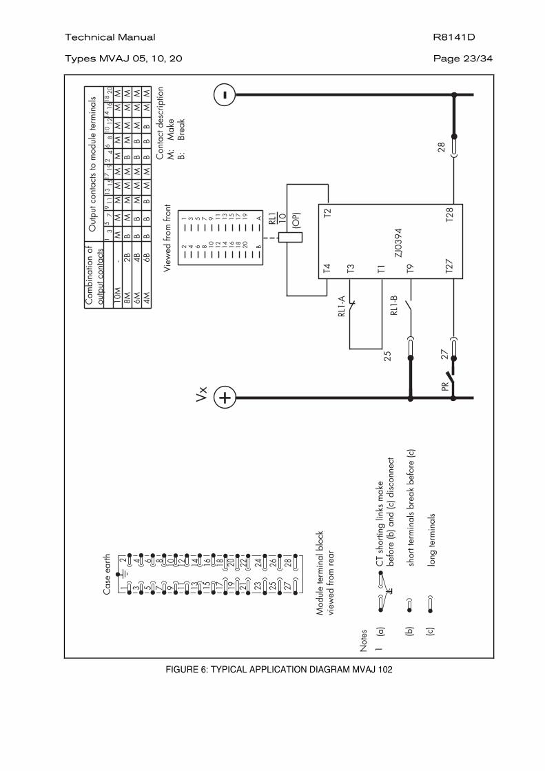
FIGURE 6: TYPICAL APPLICATION DIAGRAM MVAJ 102
R8141D Technical Manual Page 24/34
Types MVAJ 05, 10, 20
'$
,
-
.
-
,
.-,
)
*
)
*)
!
"
#$
5
% &"
"
"
&
5"
&
5"
$
5
)5
6
"5
!/!"
0/0
"
.!
1!
!!
!!
!!
!!
!
!
0
0!
!!
!0
!!
!!
-!
,0
00
!!
!0
0!
!!
,!
-0
00
0!
!0
00
!!
!
0
00
00
!0
00
0!
)
*)*
-
,-
,
.
.
) *
*
) +
, - .
,
. 0
-
.
1+
%%
23.)*)
4'(
%
%
%)
%
%,%
,
%)%
)
,
)
1
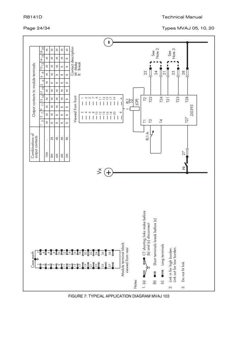
FIGURE 7: TYPICAL APPLICATION DIAGRAM MVAJ 103
Technical Manual R8141D Types MVAJ 05, 10, 20
Page 25/34
.!
1!
!!
!!
!!
!!
!!
0
0!
!!
!0
!!
!!
-!
,0
00
!!
!0
0!
!!
,!
-0
00
0!
!0
00
!!
!
0
00
00
!0
00
0!
)
*)*
.
,-
.
,
-
!/!"
0/0"
'$
)"
7
& 5
% &"
"
&
"
"
&
"
$
!
"
#$
) * )
*
)
, - .
,
-
.
,
-
)
.
1+
% %
% %-
23.)*)
10
14'(
-
%
%
%%
)
%
%
%,%
,
%)%
)
,
)
, - .
,
-
.
0
) *
)
*
+
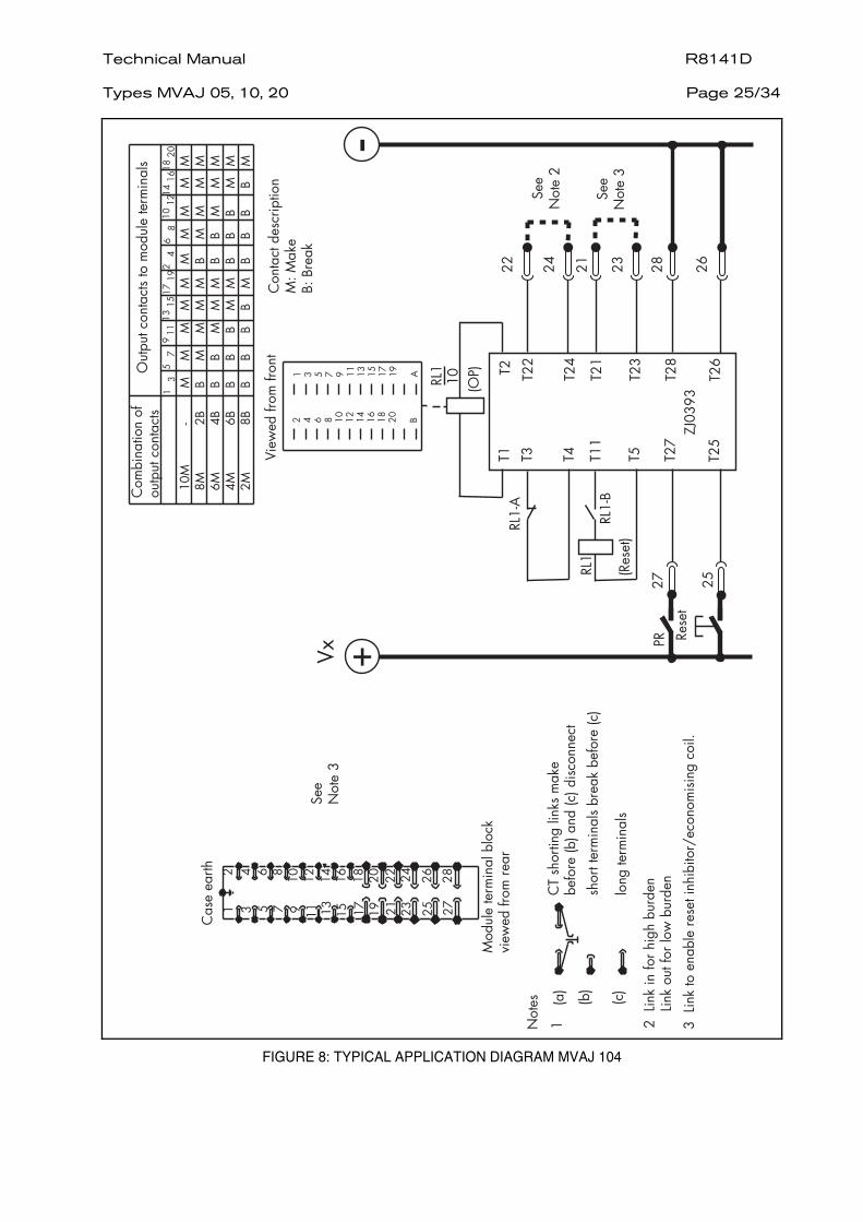
FIGURE 8: TYPICAL APPLICATION DIAGRAM MVAJ 104
R8141D Technical Manual Page 26/34
Types MVAJ 05, 10, 20
.!
1!
!!
!!
!!
!!
!!
0
0!
!!
!0
!!
!!
-!
,0
00
!!
!0
0!
!!
,!
-0
00
0!
!0
00
!!
!
0
00
00
!0
00
0!
!/
!"
0/0
"
)
*)
*
.
,-
.
,
-
, - .
,
-
.
0
) *
)
*
+
'$
% &"
"
&
"
.
1+
% %
% %-
23.)*)
10
14'(
-
!
"
#$
) , -
),
*.
),
-
*.
-
5
"
&
"
$
)5
"
7
&
%
%
%%
)
%
%
%,%
,
%)%
)
,
)
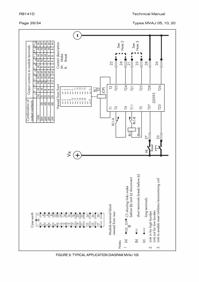
FIGURE 9: TYPICAL APPLICATION DIAGRAM MVAJ 105
Technical Manual R8141D Types MVAJ 05, 10, 20
Page 27/34
"
&
"
$
&
%
%
,
/!/
!"
0/0
"
!
"
#$
)
,-,
, - .
,
-
.
0
) *
)
*
+
,,),,
),.
.
*)))))
)*
.
,
*)
*
).)-
,-
),)-
,,,
5 "
7
7
7
"7
"
.!
1
!
0
-!
,0
,!
-0
)
!
0
))
.!
.0
,)
!
0
,,
!
!!
!!
!!
!!
!
0
!!
!!
0!
!!
!
)0
0!
!!
00
!!
!
,0
00
!!
00
0!
!
).
)
),
)-
)
,.
,
,,
,-
,
0
*
)
))
)
)
)*
,
,)
,
,
+
!
"
#$
% &"
"
&
"
)"
&
5
) * )
*
)
, - .
,
-
.
,
-
)*
*
)
))
)
)
,
,)
,
,
). )
),
)-
)
,
,,
,-
,
,.
,%
8
&
"
%
%
5
.
)
.
'(
)
,
)
1+
%,7%*
%)7%
)1+
%
%
%,
%
%)
%
%.
%%
%
23.)*)
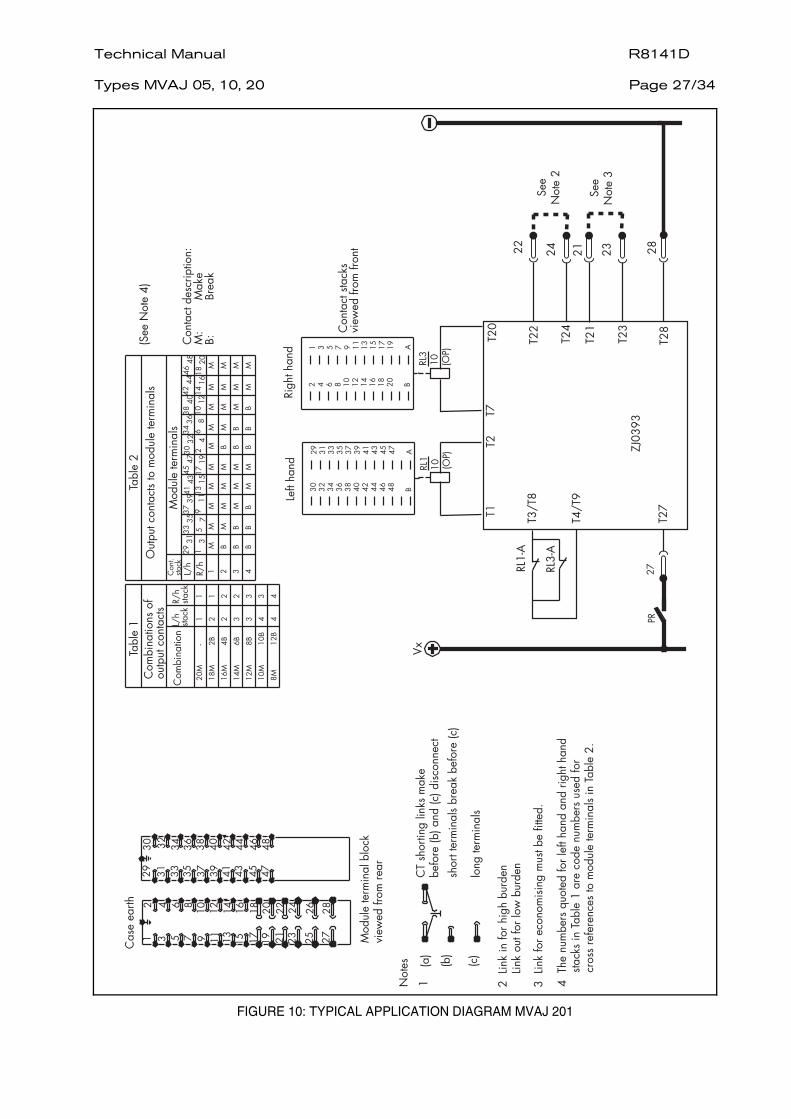
FIGURE 10: TYPICAL APPLICATION DIAGRAM MVAJ 201
R8141D Technical Manual Page 28/34
Types MVAJ 05, 10, 20
!!
!!
!!
!!
!!
0!
!!
!0
!!
!!
)
00
!!
!0
0!
!!
,
00
0!
!0
00
!!
%
!
5 "
!/
!"
0/0
"
7
7
)
*)*
-
,-
,
.
.
*)))))
)*,,),,
),)-
,,,
).)
),.
,-,
%
7
"
7
"
.!
1
!
0
-!
,0
,!
-0
)
!
0
))
.!
.0
,)
!
0
,,
"
#$
&
, - .
,
. 0
-
) *
)
* +
).
)
),
)-
)
,
,-
, 0
,,
,.
*
)
))
)
)
,
,
, +
,)
)*
!
"
#$
5
% &"
"
"
&
,
-
.
-
,
.-,
)
*
)
*)
.
,
-
,
,-
,,
,
,.
)
)-
),
)
).
,*
)
,
,
,)
,
)*
)
)
))
)
*
5
%
8
&
"
%
%
5
.
)
.
'(
1+
%7%
%)7%
)1+
%
%%
%-%
%,
23.)*)
%*
10
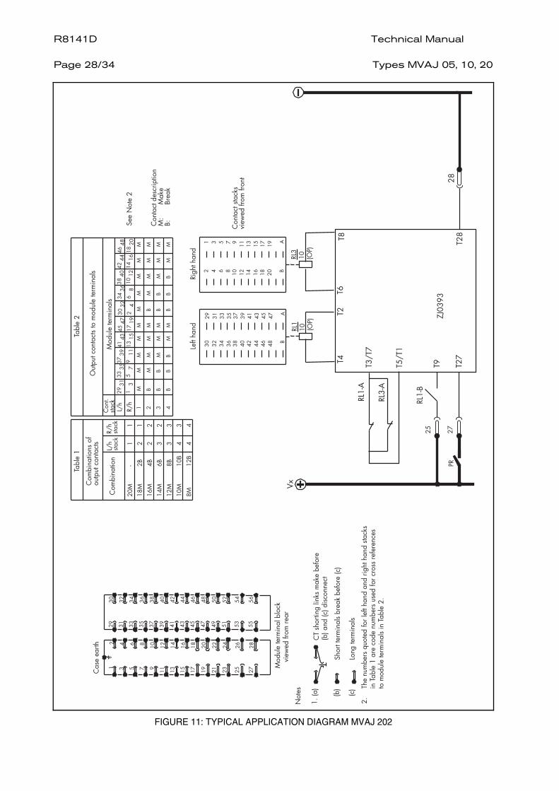
FIGURE 11: TYPICAL APPLICATION DIAGRAM MVAJ 202
Technical Manual R8141D Types MVAJ 05, 10, 20
Page 29/34
%
%
!
5 "
7
"
7
"
)
!/
!"
0/0
"
&
!
!!
!!
!!
!!
!
0
!!
!!
0!
!!
!
)0
0!
!!
00
!!
!
,0
00
!!
00
0!
!
0
00
0!
00
00
!
*))))
)
))*,,)
*)
,,
*
,
).)),)-),.
-
.
,,,
,-
,-,
.
7
7
, - .
,
-
.
0
) *
)
*
+
).
)
),
)-
)
,.
,
,,
,-
,
0
*
)
))
)
)
)*
,
,)
,
,
+
"#$
.!
1
!
0
-!
,0
,!
-0
)
!
0
))
.!
.0
,)
!
0
,,
-!
,0
,
,!
-0
.
)
.
'(
!
"
#$
% &"
"
&
"
"
&
"
$
)6
"
,%
8
&
"
%
%
5
),
-
*.
)
,
-
*
.
)
,
-
*
).
)
)
))
),
)
)-
)
)
)*
,.
,
,
,)
,,
,
,-
,
,
)
,
)
1+
%,7%*
%)7%
)1+
%
%
%,
%
%)
%
%.
%%
%
23.)*)
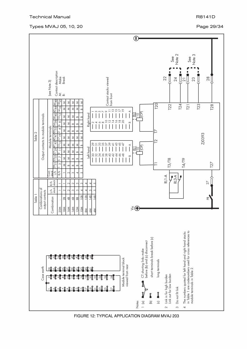
FIGURE 12: TYPICAL APPLICATION DIAGRAM MVAJ 203
R8141D Technical Manual Page 30/34
Types MVAJ 05, 10, 20
&
%
,
"
#$
7
"7
"
.!
1
!
0
-!
,0
,!
-0
)
!
0
))
.!
.0
,)
!
0
,,
-!
,0
,
,!
-0
%
!
5 "
!
!!
!!
!!
!!
!
0
!!
!!
0!
!!
!
)0
0!
!!
00
!!
!
,0
00
!!
00
0!
!
0
00
0!
00
00
!
,-,
,,),,
),.
*))
)))
)*
).)),)-
,,,
7
.
)
.
,
*
)
*
-
,-
7
!/
!"
0/0
"
, - .
,
-
.
0
) *
)
*
+
).
)
),
)-
)
,.
,
,,
,-
,
0
*
)
))
)
)
)*
,
,)
,
,
+
% &"
"
&
"
&
"
$
)"
&
5
,%
8
&
"
%
%
5
"
!
"
#$
) * )
*
)
, - .
,
-
.
,
-
)*
*
)
))
)
)
,
,)
,
). )
),
)-
)
,
,,
,-
,.
,
,
,*
.
)
,
-
.
)
.
'(
)
,
)
1+
%,7%*
%)7%
)1+
%
%
%,
%
%)
%
%.
%%
%
23.)*)
-
%-
%
10
%7%-
%.7%
)10
)
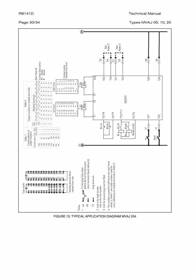
FIGURE 13: TYPICAL APPLICATION DIAGRAM MVAJ 204
Technical Manual R8141D Types MVAJ 05, 10, 20
Page 31/34
&
%
,
"
#$
7
"7
"
.!
1
!
0
-!
,0
,!
-0
)
!
0
))
.!
.0
,)
!
0
,,
-!
,0
,
,!
-0
%
!
5 "
!
!!
!!
!!
!!
!
0
!!
!!
0!
!!
!
)0
0!
!!
00
!!
!
,0
00
!!
00
0!
!
0
00
0!
00
00
!
,-,
,,),,
),.
*))
)))
)*
).)),)-
,,,
7
.
)
.
,
*
)
*
-
,-
7
!/
!"
0/0
"
, - .
,
-
.
0
) *
)
*
+
).
)
),
)-
)
,.
,
,,
,-
,
0
*
)
))
)
)
)*
,
,)
,
,
+
!
"
#$
) * )
*
)
, - .
,
-
.
,
-
)*
*
)
))
)
)
,
,)
,
). )
),
)-
)
,
,,
,-
,.
,
,
% &"
"
&
"
&
"
$
)"
&
5
,%
8
&
"
%
%
5
"
.
)
.
'(
)
,
)
1+
%,7%*
%)7%
)1+
%
%
%,
%
%)
%
%.
%%
%
23.)*)
-
%-
%
10
%7%-
%.7%
)10
)
FIGURE 14: TYPICAL APPLICATION DIAGRAM MVAJ 205
R8141D Technical Manual Page 32/34
Types MVAJ 05, 10, 20
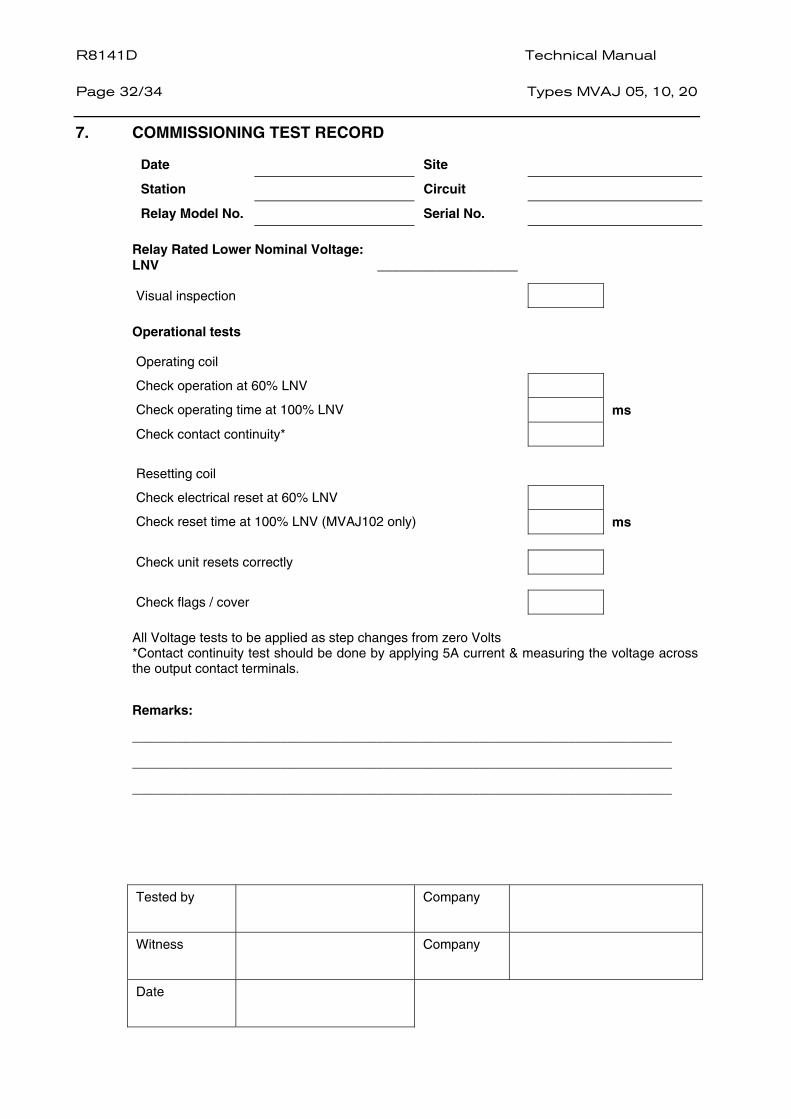
7. COMMISSIONING TEST RECORD
Date Site
Station Circuit
Relay Model No. Serial No.
Relay Rated Lower Nominal Voltage: LNV ___________________
Visual inspection
Operational tests
Operating coil
Check operation at 60% LNV
Check operating time at 100% LNV ms
Check contact continuity*
Resetting coil
Check electrical reset at 60% LNV
Check reset time at 100% LNV (MVAJ102 only) ms
Check unit resets correctly
Check flags / cover
All Voltage tests to be applied as step changes from zero Volts *Contact continuity test should be done by applying 5A current & measuring the voltage across the output contact terminals.
Remarks:
_________________________________________________________________________
_________________________________________________________________________
_________________________________________________________________________
Tested by
Company
Witness
Company
Date
Technical Manual R8141D Types MVAJ 05, 10, 20
Page 33/34
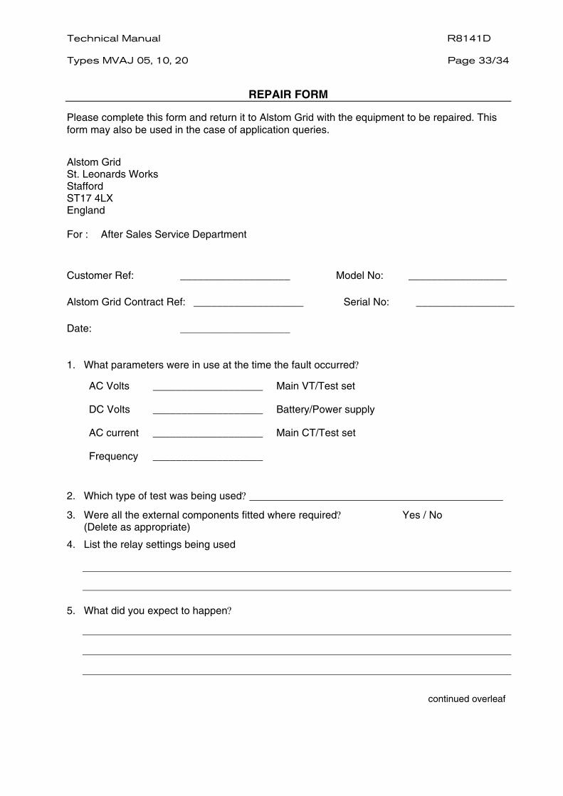
REPAIR FORM
Please complete this form and return it to Alstom Grid with the equipment to be repaired. This form may also be used in the case of application queries.
Alstom Grid St. Leonards Works Stafford ST17 4LX England For : After Sales Service Department
Customer Ref: ___________________ Model No: _________________
Alstom Grid Contract Ref: ___________________ Serial No: _________________
Date: ___________________
1. What parameters were in use at the time the fault occurred?
AC Volts ___________________ Main VT/Test set
DC Volts ___________________ Battery/Power supply
AC current ___________________ Main CT/Test set
Frequency ___________________
2. Which type of test was being used?
3. Were all the external components fitted where required? Yes / No (Delete as appropriate)
4. List the relay settings being used
5. What did you expect to happen?
continued overleaf

R8141D Technical Manual Page 34/34
Types MVAJ 05, 10, 20
6. What did happen?
7. When did the fault occur?
Instant Yes / No Intermittent Yes / No
Time delayed Yes / No (Delete as appropriate)
By how long? _________________
8. What indications if any did the relay show?
9. Was there any visual damage?
10. Any other remarks which may be useful:
Signature
Title
Name (in capitals) Company name


Alstom Grid Substation Automation Solutions Business www.alstom.com/grid Alstom Grid Worldwide Contact Centre online 24 hours a day: +44 (0) 1785 250 070 www.alstom.com/grid/contactcentre/
PUBL
ICAT
ION:
R81
41D


