MV - HVS Systemhvssystem.com/documentations/Moritex_lens-catalog-int.pdf.pdf · Machine Vision...
88
Machine Vision General Catalog MV Lens Vol.001 MORITEX and SCHOTT Machine Vision General Catalo g Lens 2 rue René Laennec 51500 Taissy France Fax: 03 26 85 19 08, Tel : 03 26 82 49 29 E-mail:[email protected] Site web : www.hvssystem.com
Transcript of MV - HVS Systemhvssystem.com/documentations/Moritex_lens-catalog-int.pdf.pdf · Machine Vision...
Machine VisionGeneral Catalog
MV
2011
.10
MV
-L-E
520
0 P
rint
ed in
Ger
man
y
Lens
Asia
MORITEX CorporationSunny Building Ikebukuro4-39-11 Higashi Ikebukuro,Toshima-ku, Tokyo, 170-0013JapanTel : +81-3-6367-3634Fax: +81-3-3590-6627E-mail : [email protected] www.moritex.co.jp
MORITEX Asia Co., Ltd.Units 1201A and 1211 - 1212 of Tower 1 of Ever Gain Plaza, 88 Container Port Road, Kwai Chung, New Territories, Hong KongTel : +852-2439-0968 Fax: +852-2439-0377E-mail : [email protected]
MORITEX Singapore Pte Ltd. Blk 211 Woodlands Avenue 9 #04-84Woodlands Spectrum II, Singapore 738960Tel : +65-6515-9368Fax: +65-6515-9360E-mail : [email protected] Lighting and ImagingSCHOTT ShanghaiUnit 301, Innov Tower, No.1801 Hongmei Road,Shanghai, PRC (200233)Tel : +86(0)21 33678000 - 170Fax: +86(0)21 33678080E-mail : [email protected]/china
Lighting and ImagingSCHOTT TAIWAN Ltd.8F-3, No. 126, Sec.4Nanking E. Road,Taipei 105, TaiwanTel : +886(2) 2570-9626Fax: +886(2) 2570-9628 E-mail : [email protected]/taiwan
Europe
Lighting and ImagingSCHOTT AGOtto Schott Strasse 2, 55127 Mainz GermanyTel : +49(0)6131/66-7752Fax: +49(0)6131/66-7850E-mail : [email protected]/lightingimaging
Lighting and ImagingSCHOTT Benelux B.V.Randweg 3A, 4104 AC Culemborg NetherlandsTel : +31(0)344-670911Fax: +31(0)344-621802E-mail : [email protected]/lightingimaging Lighting and ImagingSCHOTT France SAS6 bis, rue Fournier, FR-Clichy, FranceTel : +33(0)14087-3900Fax: +33(0)14270-7322E-mail : [email protected]/lightingimaging Lighting and ImagingSCHOTT UK Ltd.122 Drummond Road, ST16 3EL Stafford, Great BritainTel : +44(0)1785-223166Fax: +44(0)1785-223522E-mail : [email protected]/lightingimaging
Lighting and ImagingSCHOTT Glas Export GmbHRasko Building, 40 Ha'atzmaut St., 56304 Yehud, IsraelTel : +972(0)353617-11Fax: +972(0)353617-10E-mail : [email protected]/lightingimaging
North America
Lighting and ImagingSCHOTT North America, Inc.6862 Santa Teresa Blvd.San Jose, CA 95119 U.S.A.Tel : +1-408-363-2100Fax: +1-408-363-9980E-mail : [email protected]/lightingimaging
Vol.001
MO
RIT
EX an
d SC
HO
TT
Machine V
ision General C
atalo gLens
Vo
l.001
2 rue René Laennec 51500 Taissy France Fax: 03 26 85 19 08, Tel : 03 26 82 49 29
E-mail:[email protected] web : www.hvssystem.com
Introduction
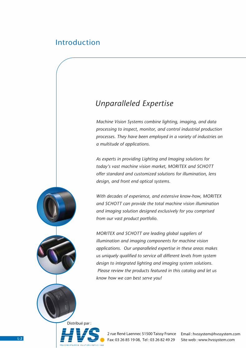
Machine Vision Systems combine lighting, imaging, and data
processing to inspect, monitor, and control industrial production
processes. They have been employed in a variety of industries on
a multitude of applications.
As experts in providing Lighting and Imaging solutions for
today’s vast machine vision market, MORITEX and SCHOTT
offer standard and customized solutions for illumination, lens
design, and front end optical systems.
With decades of experience, and extensive know-how, MORITEX
and SCHOTT can provide the total machine vision illumination
and imaging solution designed exclusively for you comprised
from our vast product portfolio.
MORITEX and SCHOTT are leading global suppliers of
illumination and imaging components for machine vision
applications. Our unparalleled expertise in these areas makes
us uniquely qualified to service all different levels from system
design to integrated lighting and imaging system solutions.
�Please review the products featured in this catalog and let us
know how we can best serve you!
Unparalleled Expertise
L-2 L-87
Dimensions and specifications in this catalog may vary. Before purchasing,please check the delivery specifications or diagrams.
*Company and product names stated in this catalog are trademarks or registered trademarks of their respective companies.*Product specifications, design, values, etc. may vary.*The contents in this catalog are for the present as of October 2011.Email : 2 rue René Laennec 51500 Taissy France
Fax: 03 26 85 19 08, Tel : 03 26 82 49 [email protected]
Site web : www.hvssystem.com
Distribué par :

Introduction
Machine Vision Systems combine lighting, imaging, and data
processing to inspect, monitor, and control industrial production
processes. They have been employed in a variety of industries on
a multitude of applications.
As experts in providing Lighting and Imaging solutions for
today’s vast machine vision market, MORITEX and SCHOTT
offer standard and customized solutions for illumination, lens
design, and front end optical systems.
With decades of experience, and extensive know-how, MORITEX
and SCHOTT can provide the total machine vision illumination
and imaging solution designed exclusively for you comprised
from our vast product portfolio.
MORITEX and SCHOTT are leading global suppliers of
illumination and imaging components for machine vision
applications. Our unparalleled expertise in these areas makes
us uniquely qualified to service all different levels from system
design to integrated lighting and imaging system solutions.
�Please review the products featured in this catalog and let us
know how we can best serve you!
Since 2007, MORITEX and SCHOTT have cooperated on a global scale.
Our goal has always been to provide the ultimate products and services to
our customers worldwide. By utilizing the bundled experience and expertise
of these two established companies, we have made this goal a reality.
As an established leader in machine vision systems with an impeccable
track record of innovation, MORITEX is the only provider that can service
all different levels from system design to integrated system solutions.
The SCHOTT Lighting and Imaging division offers a broad range of LED
and fiber optic solutions focusing on illumination, light and image
transmission. In addition, SCHOTT also offers superior hybrid solutions
utilizing the best of LED and fiber optic technologies.
For the first time, MORITEX and SCHOTT present their entire Machine
Vision portfolio together in one catalog at your convenience and reference.
Thank you for taking the time to learn about MORITEX and SCHOTT and
how we can provide you with the ultimate in Machine Vision solutions.
If you would like more information about any of our products, please don’t
hesitate to contact us.
MORITEX and SCHOTT, Unparalleled Expertise!
Unparalleled Expertise Your Global Lighting and Imaging Alliance
L-3
311766_MV_LensKatalog.indd 3 07.09.11 15:00
San JoseU.S.A.
Hong KongChina
Singapore
TokyoJapan
MainzGermany
ParisFrance
YehudIsrael
San JoseU.S.A.
Hong KongChina
Singapore
TokyoJapan
MainzGermany
ParisFrance
YehudIsrael
TaipeiTaiwanTaipeiTaiwan
ShanghaiChinaShanghaiChina
TielNetherlandsTielNetherlands
StaffordUnited KingdomStaffordUnited Kingdom
TokyoTokyoTokyoTokyoTokyoTokyoTokyoJapanJapanJapanJapanJapanTokyoTokyoTokyoTokyoTokyoTokyoTokyoTokyoTokyoTokyoTokyoTokyoTokyoTokyoTokyoTokyoTokyoTokyoTokyoTokyoTokyoTokyoTokyoTokyoTokyoTokyoTokyoTokyoTokyoTokyoTokyoTokyoTokyoTokyoTokyoTokyoTokyoTokyoTokyoTokyoTokyoTokyoTokyoTokyoTokyoTokyoTokyoTokyoTokyoTokyoTokyoTokyoTokyoTokyoTokyoTokyoTokyoTokyoTokyoTokyoTokyoTokyoTokyoTokyoTokyoTokyoJapanJapanJapanJapanJapanJapanJapanJapanJapanJapanJapanJapanJapanJapanJapanJapanJapanJapanJapanJapanJapanJapanJapanJapanJapanJapanJapanJapanJapanJapanJapanJapanJapanJapanJapanJapanJapanJapanJapanJapanJapanJapanJapanJapanJapanJapanJapanJapanJapanJapanJapanJapan
ShanghaiChinaShanghaiShanghaiShanghaiShanghaiChinaChinaChinaChina
ChinaChinaChinaChina
TaipeiTaiwanTaipeiTaipeiTaipeiTaipeiTaipeiTaipeiTaipeiTaipeiTaiwanTaiwanTaiwanTaiwan
Hong KongChinaHong KongHong KongHong KongChinaChinaChinaChina
ShanghaiShanghaiShanghaiShanghaiShanghaiChinaShanghaiShanghaiShanghaiChinaChinaChinaChinaShanghaiShanghaiShanghaiShanghaiShanghai
TaipeiTaipeiTaiwanTaipeiTaipeiTaipeiTaipeiTaipeiTaipeiTaipeiTaipeiTaiwanTaiwanTaiwanTaiwanTaiwanTaiwanTaiwanTaiwan
Hong KongHong KongHong KongHong KongHong KongTaiwanTaiwanTaiwanTaiwanTaiwan
ShanghaiChinaShanghaiShanghaiShanghaiChinaChinaChinaChina
SingaporeSingaporeSingaporeSingaporeSingapore
Hong KongChinaHong KongHong KongHong KongHong KongChinaChinaChinaChinaHong KongHong KongHong KongHong KongChinaChinaChinaChinaHong KongHong KongHong KongHong KongHong KongHong KongHong KongHong Kong
San JoseU.S.A.San JoseSan JoseSan JoseSan JoseU.S.A.U.S.A.U.S.A.U.S.A.
YehudYehudYehudYehudYehudIsraelIsraelIsraelIsraelIsraelYehudYehudYehudYehudYehudYehudYehudYehudYehudYehudYehudYehudYehudYehudYehudYehudYehudYehudYehudYehudYehudYehudYehudIsraelIsraelIsraelIsraelIsraelIsraelIsraelIsraelIsraelIsraelIsraelIsraelIsraelIsraelIsraelIsraelIsrael
MainzGermany
ParisFrance
MainzMainzMainzMainzGermanyGermanyGermanyGermany
ParisParisParisParisParisParisParisFranceFranceFranceFrance
MainzGermany
ParisFrance
MainzMainzMainzMainzGermanyGermanyGermanyGermany
ParisParisParisParisParisParisParisFranceFranceFranceFrance
NetherlandsNetherlandsNetherlandsNetherlandsNetherlandsNetherlandsNetherlandsNetherlandsNetherlands
StaffordStaffordStaffordStaffordStaffordStaffordUnited KingdomUnited KingdomUnited KingdomUnited KingdomUnited KingdomUnited KingdomStaffordStaffordStaffordStaffordStaffordStaffordStaffordStaffordStaffordStaffordStaffordStaffordStaffordStaffordStaffordStaffordStaffordStaffordStaffordStaffordStaffordStaffordStaffordStaffordStaffordStaffordStaffordStaffordStaffordStaffordStaffordStaffordStaffordStaffordStaffordStaffordStaffordStaffordStaffordStaffordUnited KingdomUnited KingdomUnited KingdomUnited KingdomUnited KingdomUnited KingdomUnited KingdomUnited KingdomUnited KingdomUnited KingdomUnited KingdomUnited KingdomUnited KingdomUnited KingdomUnited KingdomUnited KingdomUnited KingdomUnited KingdomUnited KingdomUnited KingdomUnited KingdomUnited KingdomUnited KingdomUnited KingdomUnited KingdomUnited KingdomUnited KingdomUnited KingdomUnited KingdomUnited KingdomUnited KingdomUnited KingdomUnited KingdomUnited KingdomUnited KingdomUnited KingdomUnited KingdomUnited KingdomUnited KingdomUnited KingdomUnited KingdomUnited KingdomUnited KingdomUnited KingdomUnited KingdomUnited KingdomUnited KingdomUnited KingdomUnited KingdomUnited KingdomUnited KingdomUnited KingdomUnited KingdomUnited KingdomUnited KingdomUnited KingdomUnited KingdomUnited KingdomUnited KingdomUnited KingdomUnited KingdomUnited KingdomUnited KingdomStaffordStaffordStaffordStaffordStaffordStaffordStaffordStaffordStaffordStaffordStaffordStaffordStaffordStaffordStaffordStaffordStaffordStaffordStafford
MainzGermany
ParisParisFrance
MainzMainzMainzMainzGermanyGermanyGermanyGermany
ParisParisParisParisParisParisParisFranceFranceFranceFrance
NetherlandsNetherlandsNetherlandsNetherlandsNetherlandsNetherlandsNetherlandsNetherlands
StaffordStaffordUnited KingdomUnited KingdomStaffordStaffordStaffordStaffordStaffordStaffordStaffordStaffordStaffordStaffordStaffordStaffordStaffordStaffordStaffordStaffordStaffordStaffordUnited KingdomUnited KingdomUnited KingdomUnited KingdomUnited KingdomUnited KingdomUnited KingdomUnited KingdomUnited KingdomUnited KingdomUnited KingdomUnited KingdomUnited KingdomUnited KingdomUnited KingdomUnited KingdomUnited KingdomUnited KingdomUnited KingdomUnited Kingdom
NetherlandsNetherlandsNetherlandsNetherlandsNetherlands
United KingdomUnited KingdomUnited KingdomUnited KingdomUnited KingdomUnited KingdomUnited KingdomUnited KingdomUnited KingdomUnited KingdomUnited KingdomUnited KingdomUnited KingdomUnited KingdomStaffordStaffordStaffordStaffordStaffordStaffordStaffordStaffordStaffordStaffordStaffordStaffordStaffordStaffordStaffordStaffordStaffordStaffordStaffordStaffordStaffordStaffordStaffordStaffordStaffordStaffordStaffordUnited KingdomUnited KingdomUnited KingdomUnited KingdomUnited KingdomUnited KingdomUnited KingdomUnited KingdomUnited KingdomUnited KingdomUnited KingdomUnited KingdomUnited KingdomUnited KingdomUnited KingdomUnited Kingdom
MainzGermany
France
MainzMainzMainzMainzGermanyGermanyGermanyGermany
FranceFranceFranceFranceTielTielNetherlandsTielTielTielTielTielTielTielTielNetherlandsNetherlandsNetherlandsNetherlands
United KingdomUnited KingdomUnited KingdomUnited KingdomUnited KingdomUnited KingdomUnited KingdomUnited KingdomUnited KingdomUnited KingdomUnited KingdomUnited KingdomUnited KingdomUnited KingdomUnited KingdomUnited KingdomUnited KingdomUnited KingdomUnited Kingdom
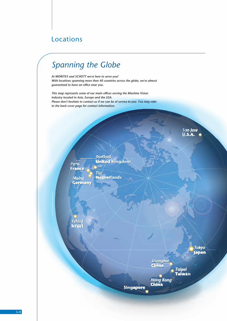
At MORITEX and SCHOTT we're here to serve you! With locations spanning more then 40 countries across the globe, we're almost guaranteed to have an office near you.
This map represents some of our main offices serving the Machine Vision industry located in Asia, Europe and the USA. Please don't hesitate to contact us if we can be of service to you. You may refer to the back cover page for contact information.
Spanning the Globe
Locations
L-4
New Products
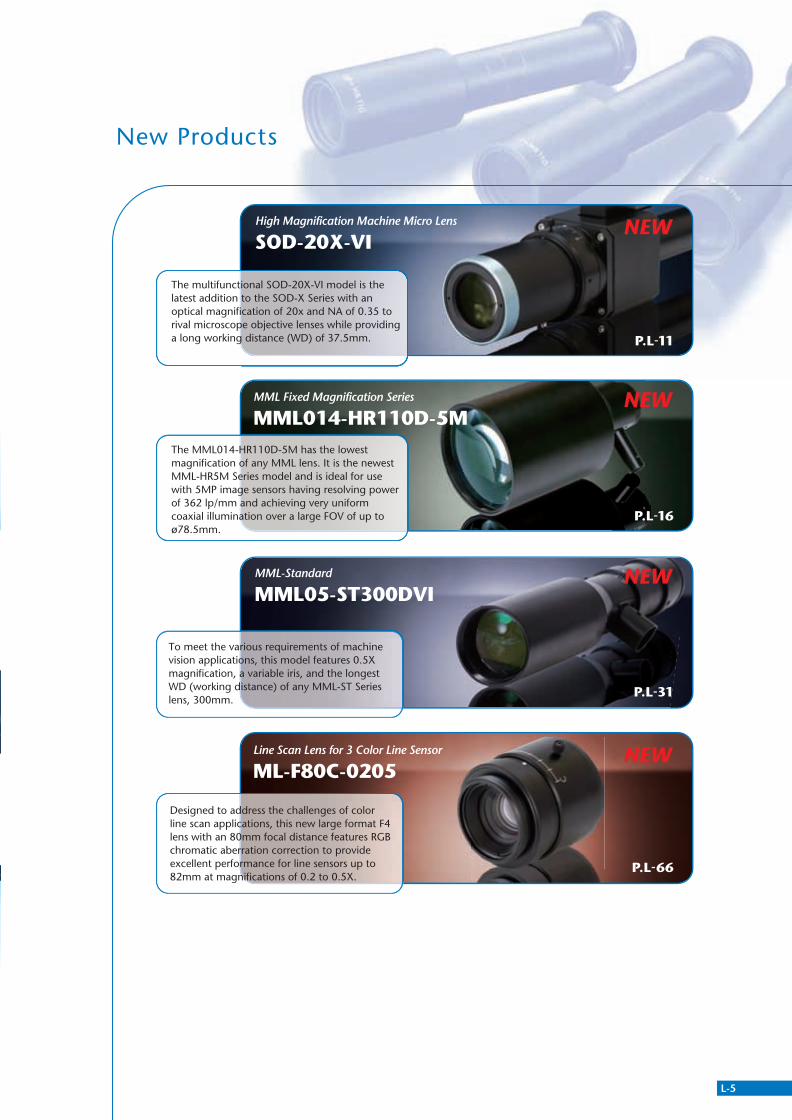
MML Fixed Magnification Series
MML014-HR110D-5MNEW
P.L-16
The MML014-HR110D-5M has the lowest magnification of any MML lens. It is the newest MML-HR5M Series model and is ideal for use with 5MP image sensors having resolving power of 362 lp/mm and achieving very uniform coaxial illumination over a large FOV of up to ø78.5mm.
High Magnification Machine Micro Lens
SOD-20X-VINEW
P.L-11
The multifunctional SOD-20X-VI model is the latest addition to the SOD-X Series with an optical magnification of 20x and NA of 0.35 to rival microscope objective lenses while providing a long working distance (WD) of 37.5mm.
MML-Standard
MML05-ST300DVINEW
P.L-31
Line Scan Lens for 3 Color Line Sensor
ML-F80C-0205NEW
P.L-66
To meet the various requirements of machine vision applications, this model features 0.5X magnification, a variable iris, and the longest WD (working distance) of any MML-ST Series lens, 300mm.
Designed to address the challenges of color line scan applications, this new large format F4 lens with an 80mm focal distance features RGB chromatic aberration correction to provide excellent performance for line sensors up to 82mm at magnifications of 0.2 to 0.5X.
311766_MV_LensKatalog.indd 4 07.09.11 15:00
San JoseU.S.A.
Hong KongChina
Singapore
TokyoJapan
MainzGermany
ParisFrance
YehudIsrael
San JoseU.S.A.
Hong KongChina
Singapore
TokyoJapan
MainzGermany
ParisFrance
YehudIsrael
TaipeiTaiwanTaipeiTaiwan
ShanghaiChinaShanghaiChina
TielNetherlandsTielNetherlands
StaffordUnited KingdomStaffordUnited Kingdom
At MORITEX and SCHOTT we're here to serve you! With locations spanning more then 40 countries across the globe, we're almost guaranteed to have an office near you.
This map represents some of our main offices serving the Machine Vision industry located in Asia, Europe and the USA. Please don't hesitate to contact us if we can be of service to you. You may refer to the back cover page for contact information.
Spanning the Globe
Locations
L-5
New Products
MML Fixed Magnification Series
MML014-HR110D-5MNEW
P.L-16
The MML014-HR110D-5M has the lowest magnification of any MML lens. It is the newest MML-HR5M Series model and is ideal for use with 5MP image sensors having resolving power of 362 lp/mm and achieving very uniform coaxial illumination over a large FOV of up to ø78.5mm.
High Magnification Machine Micro Lens
SOD-20X-VINEW
P.L-11
The multifunctional SOD-20X-VI model is the latest addition to the SOD-X Series with an optical magnification of 20x and NA of 0.35 to rival microscope objective lenses while providing a long working distance (WD) of 37.5mm.
MML-Standard
MML05-ST300DVINEW
P.L-31
Line Scan Lens for 3 Color Line Sensor
ML-F80C-0205NEW
P.L-66
To meet the various requirements of machine vision applications, this model features 0.5X magnification, a variable iris, and the longest WD (working distance) of any MML-ST Series lens, 300mm.
Designed to address the challenges of color line scan applications, this new large format F4 lens with an 80mm focal distance features RGB chromatic aberration correction to provide excellent performance for line sensors up to 82mm at magnifications of 0.2 to 0.5X.
311766_MV_LensKatalog.indd 5 07.09.11 15:00
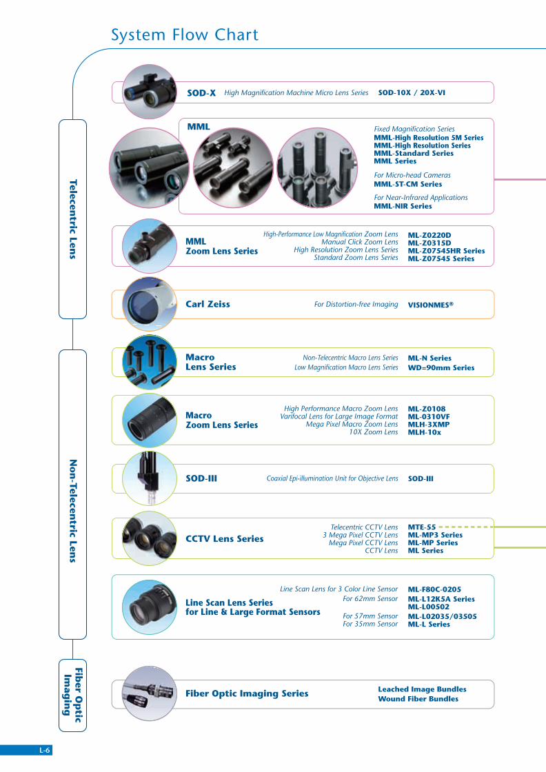
System Flow Chart
MML
MML-ST-CM Series
MML-NIR Series
MML-High Resolution 5M SeriesMML-High Resolution SeriesMML-Standard SeriesMML Series
Fixed Magnification Series
For Near-Infrared Applications
For Micro-head Cameras
Accessories
Leached Image BundlesWound Fiber Bundles
SOD-III
Macro Zoom Lens Series
CCTV Lens Series
MacroLens Series
Line Scan Lens Seriesfor Line & Large Format Sensors
Fiber Optic Imaging Series
Telecentric Len
sFib
er Op
ticIm
agin
gN
on
-Telecentric Len
s
SOD-X SOD-10X / 20X-VIHigh Magnification Machine Micro Lens Series
ML-Z0220DML-Z0315DML-Z07545HR SeriesML-Z07545 Series
High-Performance Low Magnification Zoom LensManual Click Zoom Lens
High Resolution Zoom Lens SeriesStandard Zoom Lens Series
MMLZoom Lens Series
For Distortion-free ImagingCarl Zeiss VISIONMES®
High Performance Macro Zoom LensVarifocal Lens for Large Image Format
Mega Pixel Macro Zoom Lens10X Zoom Lens
Line Scan Lens for 3 Color Line SensorFor 62mm Sensor
For 57mm SensorFor 35mm Sensor
Coaxial Epi-illumination Unit for Objective Lens
Telecentric CCTV Lens3 Mega Pixel CCTV Lens
Mega Pixel CCTV LensCCTV Lens
ML-Z0108ML-0310VFMLH-3XMPMLH-10x
ML-F80C-0205ML-L12K5A SeriesML-L00502ML-L02035/03505ML-L Series
MTE-55ML-MP3 SeriesML-MP SeriesML Series
SOD-III
ML-N SeriesWD=90mm Series
Prisms
OEM Products
Adapter
90˚ Side View (Mirror)90˚ Side View (Pentaprism)Variable Optical Axis PitchVariable Pitch Side ViewDual Field of ViewCoaxial L-Shaped Adapter
Accessories
Accessories
ML-XML-MLCML-GA SeriesML-PL SeriesML-FL SeriesML-EXR Series
Rear Converter Lenses90º Mirror Prism
Grass CoversPolarizers
Ring Illumination Attachment AdaptersClose-Up Rings
MTE-075MTE-2
Converter Lenses
Guidance
Telecentric Lens Series
Non-Telecentric Lenses
Line Scan Lens Series
Partner Lens Series
Fiber Optic Imaging Series
Non-Telecentric Macro Lens SeriesLow Magnification Macro Lens Series
L-6
311766_MV_LensKatalog.indd 6 07.09.11 15:00

System Flow Chart
MML
MML-ST-CM Series
MML-NIR Series
MML-High Resolution 5M SeriesMML-High Resolution SeriesMML-Standard SeriesMML Series
Fixed Magnification Series
For Near-Infrared Applications
For Micro-head Cameras
Accessories
Leached Image BundlesWound Fiber Bundles
SOD-III
Macro Zoom Lens Series
CCTV Lens Series
MacroLens Series
Line Scan Lens Seriesfor Line & Large Format Sensors
Fiber Optic Imaging Series
Telecentric Len
sFib
er Op
ticIm
agin
gN
on
-Telecentric Len
s
SOD-X SOD-10X / 20X-VIHigh Magnification Machine Micro Lens Series
ML-Z0220DML-Z0315DML-Z07545HR SeriesML-Z07545 Series
High-Performance Low Magnification Zoom LensManual Click Zoom Lens
High Resolution Zoom Lens SeriesStandard Zoom Lens Series
MMLZoom Lens Series
For Distortion-free ImagingCarl Zeiss VISIONMES®
High Performance Macro Zoom LensVarifocal Lens for Large Image Format
Mega Pixel Macro Zoom Lens10X Zoom Lens
Line Scan Lens for 3 Color Line SensorFor 62mm Sensor
For 57mm SensorFor 35mm Sensor
Coaxial Epi-illumination Unit for Objective Lens
Telecentric CCTV Lens3 Mega Pixel CCTV Lens
Mega Pixel CCTV LensCCTV Lens
ML-Z0108ML-0310VFMLH-3XMPMLH-10x
ML-F80C-0205ML-L12K5A SeriesML-L00502ML-L02035/03505ML-L Series
MTE-55ML-MP3 SeriesML-MP SeriesML Series
SOD-III
ML-N SeriesWD=90mm Series
Prisms
OEM Products
Adapter
90˚ Side View (Mirror)90˚ Side View (Pentaprism)Variable Optical Axis PitchVariable Pitch Side ViewDual Field of ViewCoaxial L-Shaped Adapter
Accessories
Accessories
ML-XML-MLCML-GA SeriesML-PL SeriesML-FL SeriesML-EXR Series
Rear Converter Lenses90º Mirror Prism
Grass CoversPolarizers
Ring Illumination Attachment AdaptersClose-Up Rings
MTE-075MTE-2
Converter Lenses
Guidance
Telecentric Lens Series
Non-Telecentric Lenses
Line Scan Lens Series
Partner Lens Series
Fiber Optic Imaging Series
Non-Telecentric Macro Lens SeriesLow Magnification Macro Lens Series
L-7
311766_MV_LensKatalog.indd 7 07.09.11 15:00
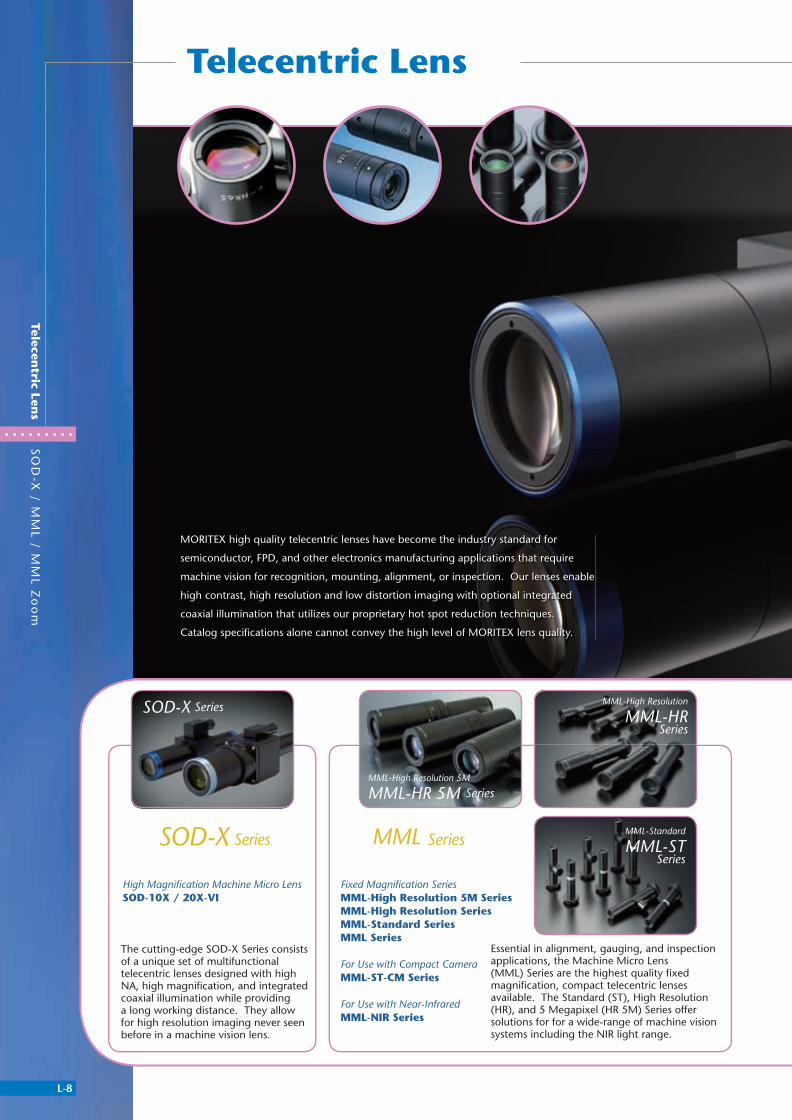
Telecentric Lens
L-8
SO
D-X
/ MM
L / MM
L Zo
om
Telecentric Len
s
SOD-X Series
The cutting-edge SOD-X Series consists of a unique set of multifunctional telecentric lenses designed with high NA, high magnifi cation, and integrated coaxial illumination while providing a long working distance. They allow for high resolution imaging never seen before in a machine vision lens.
MML-High Resolution
MML-HRSeries
MML-Standard
MML-STSeries
SOD-X Series MML Series
High Magnifi cation Machine Micro LensSOD-10X / 20X-VI
Fixed Magnifi cation SeriesMML-High Resolution 5M SeriesMML-High Resolution SeriesMML-Standard SeriesMML Series
For Use with Compact CameraMML-ST-CM Series
For Use with Near-InfraredMML-NIR Series
Essential in alignment, gauging, and inspection applications, the Machine Micro Lens (MML) Series are the highest quality fi xed magnifi cation, compact telecentric lenses available. The Standard (ST), High Resolution (HR), and 5 Megapixel (HR 5M) Series offer solutions for for a wide-range of machine vision systems including the NIR light range.
MORITEX high quality telecentric lenses have become the industry standard for
semiconductor, FPD, and other electronics manufacturing applications that require
machine vision for recognition, mounting, alignment, or inspection. Our lenses enable
high contrast, high resolution and low distortion imaging with optional integrated
coaxial illumination that utilizes our proprietary hot spot reduction techniques.
Catalog specifi cations alone cannot convey the high level of MORITEX lens quality.
MML-High Resolution 5M
MML-HR 5M Series
311766_MV_LensKatalog.indd 8 07.09.11 15:00
L-9
SO
D-X
/ MM
L / MM
L Zo
om
Telecentric Len
s
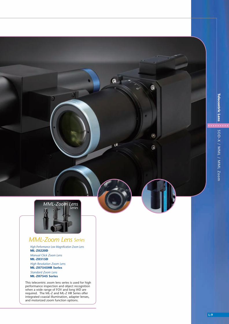
This telecentric zoom lens series is used for high performance inspection and object recognition when a wide range of FOV and long WD are required. The ML-Z and ML-Z HR Series offer integrated coaxial illumination, adapter lenses, and motorized zoom function options.
MML-Zoom LensSeries
MML-Zoom Lens SeriesHigh-Performance Low Magnifi cation Zoom LensML-Z0220D
Manual Click Zoom LensML-Z0315D
High Resolution Zoom LensML-Z07545HR Series
Standard Zoom LensML-Z07545 Series
311766_MV_LensKatalog.indd 9 07.09.11 15:01
L-10
Telecentric Lens
SO
D-1
0X
/ 20
X-V
IH
igh
Mag
nifi catio
n M
achin
e M
icro Len
s
SOD-X
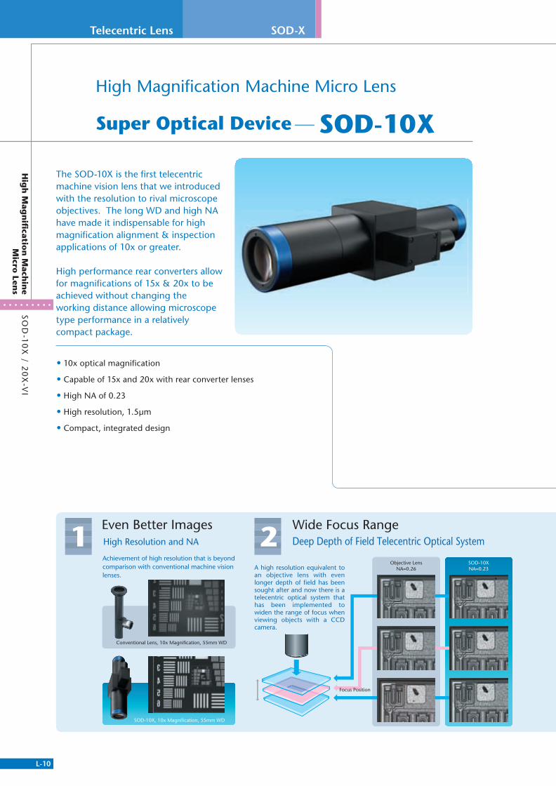
High Magnifi cation Machine Micro Lens
Super Optical Device-SOD-10X
• 10x optical magnifi cation
• Capable of 15x and 20x with rear converter lenses
• High NA of 0.23
• High resolution, 1.5μm
• Compact, integrated design
The SOD-10X is the fi rst telecentric machine vision lens that we introduced with the resolution to rival microscope objectives. The long WD and high NA have made it indispensable for high magnifi cation alignment & inspection applications of 10x or greater.
High performance rear converters allow for magnifi cations of 15x & 20x to be achieved without changing the working distance allowing microscope type performance in a relatively compact package.
Deep Depth of Field Telecentric Optical System Wide Focus Range
2Objective Lens
NA=0.26SOD-10XNA=0.23
Focus Position
A high resolution equivalent to an objective lens with even longer depth of field has been sought after and now there is a telecentric optical system that has been implemented to widen the range of focus when viewing objects with a CCD camera.
High Resolution and NA
Even Better Images1
Achievement of high resolution that is beyondcomparison with conventional machine vision lenses.
Conventional Lens, 10x Magnification, 55mm WD
SOD-10X, 10x Magnification, 55mm WD
311766_MV_LensKatalog.indd 10 07.09.11 15:01

L-11
Hig
h M
agn
ifi cation
Mach
ine M
icro Len
sS
OD
-10
X / 2
0X
-VI
• 20x optical magnifi cation
• Capable of 30x and 40x with rear converter lenses
• High NA of 0.35
• High resolution, 1μm
• Variable iris
This revolutionary 20x magnifi cation SOD series model has a high NA & resolution that put it in the microscope objective lens class.In addition, it boasts a long WD of 37.5 mm that provides you with additional space to install Illumination and motion, handling, & transfer systems.The all-in-one machine vision lens has a compact body with an integrated coaxial epi-illumination also saving space & improving on-axis light quality.
High Magnifi cation Machine Micro Lens
Super Optical Device-SOD-20X-VI
Compact4 Compact design makes
it possible to downsize peripheral parts and machinery.
Long WDEase of Use3 Improved ease of use through longer WD (working distance) while
maintaining high resolution.
Establishment of operating space Confirmation of operation status
and position possible by eyeOblique illumination is possible Separation
from heat source
Use in environmentswhere substances such aswater & oil are disturbed
Opens the possibility of using not only coaxial but ring and various other types of illumination. This increase in lighting options allows for the imaging of objects previously difficult to view and resolve.
Recognition is possible at a location with necessary separation from heat sources. Alignment and inspection are also possible during thermo compression bonding.
Observation can be performed without any effects from water, oil, and foreign objects generated or moved during processing.
Sufficient space for tooling and pick-up tools has been provided allowing the performance of operations thought to be impossible with conventional lenses. Operating position and work status can be confirmed by eye resulting in a reduction of operating errors.
NEW
311766_MV_LensKatalog.indd 11 07.09.11 15:01
L-12
Telecentric Lens
SO
D-1
0X
/ 20
X-V
IH
igh
Mag
nifi catio
n M
achin
e M
icro Len
s
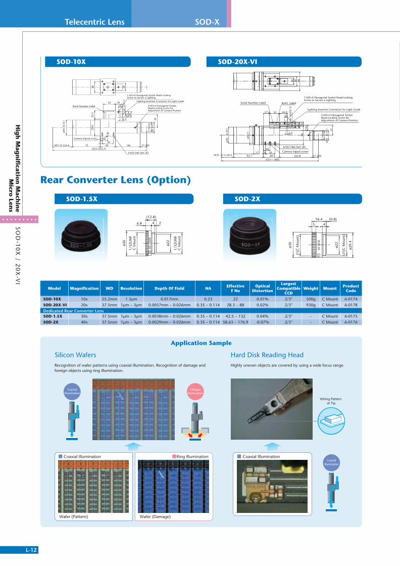
SOD-X
Recognition of wafer patterns using coaxial illumination. Recognition of damage and foreign objects using ring illumination.
Highly uneven objects are covered by using a wide focus range.
SOD-2XSOD-1.5X
Rear Converter Lens (Option)
Application Sample
30 20
32 1810
5.5
1-M3×4 Hexagonal Socket Head Locking Screw to Secure a Lighting
Lighting Insertion Connector for Light Guide
ø8 +
0.03
/ 0
ø14.
2ø1
6
3-M3×4 Hexagonal Socket Head Locking Screw for Adjustment of Camera Position
35
C m
ount
ø30
0/-0
.1
4522
.5
ø40
0/-
0.1
2030
4075WD 55.2±0.6 66 17.526(O/I=253.7)
Camera tripod screw
4-M3 Heli-Sert 2D
Serial Number Label
305102.849.492.7
20
17.526(O/I = 300)
W.D. 37.5 ±0.517 Camera tripod screw
(16)ø1
6
32 24.910
ø14.
2
5.5
ø30
0/-
0.1
C m
ount 31
ø50
0/-
0.1
20
17.4
ø56.
5
58
OC
O
30
1258
FFFFFFFF
RoHS LabelSerial Number Label
SOD
-20X-VI
ø8 +
0.05
/ 0
1-M3×4 Hexagonal Socket Head Locking Screw to Secure a Lighting
Lighting Insertion Connector for Light Guide
3-M3×4 Hexagonal Socket Head Locking Screw for Adjustment of Camera Position
4-M3 Heli-Sert 2D
SOD-10X SOD-20X-VI
Coaxial Illumination Ring Illumination
CoaxialIllumination
Oblique Illumination
Wafer (Pattern) Wafer (Damage)
Coaxial Illumination
Wiring Pattern of Tip
Coaxial Illumination
Silicon Wafers Hard Disk Reading Head
ø22
45(0.8)
ø30
ø29.
4
U1(
C M
ount
)
J1(C
Mou
nt)
16.46.8
(12.8)
ø22
4 2
ø30
1/32
UN
FC
Mou
nt
1/32
UN
FC
Mou
nt
Model Magnifi cation WD Resolution Depth Of Field NA Effective F No
Optical Distortion
Largest Compatible
CCDWeight Mount Product
Code
SOD-10X 10x 55.2mm 1.5μm 0.017mm 0.23 22 0.01% 2/3" 500g C Mount A-0174SOD-20X-VI 20x 37.5mm 1μm ~ 3μm 0.0057mm ~ 0.026mm 0.35 ~ 0.114 28.3 ~ 88 0.02% 2/3" 930g C Mount A-0178Dedicated Rear Converter LensSOD-1.5X 30x 37.5mm 1μm ~ 3μm 0.0038mm ~ 0.026mm 0.35 ~ 0.114 42.5 ~ 132 0.04% 2/3" - C Mount A-0175SOD-2X 40x 37.5mm 1μm ~ 3μm 0.0029mm ~ 0.026mm 0.35 ~ 0.114 58.63 ~ 176.9 -0.07% 2/3" - C Mount A-0176
311766_MV_LensKatalog.indd 12 07.09.11 15:01
L-13
Fixed
Mag
nifi
cation
Lens
MM
L
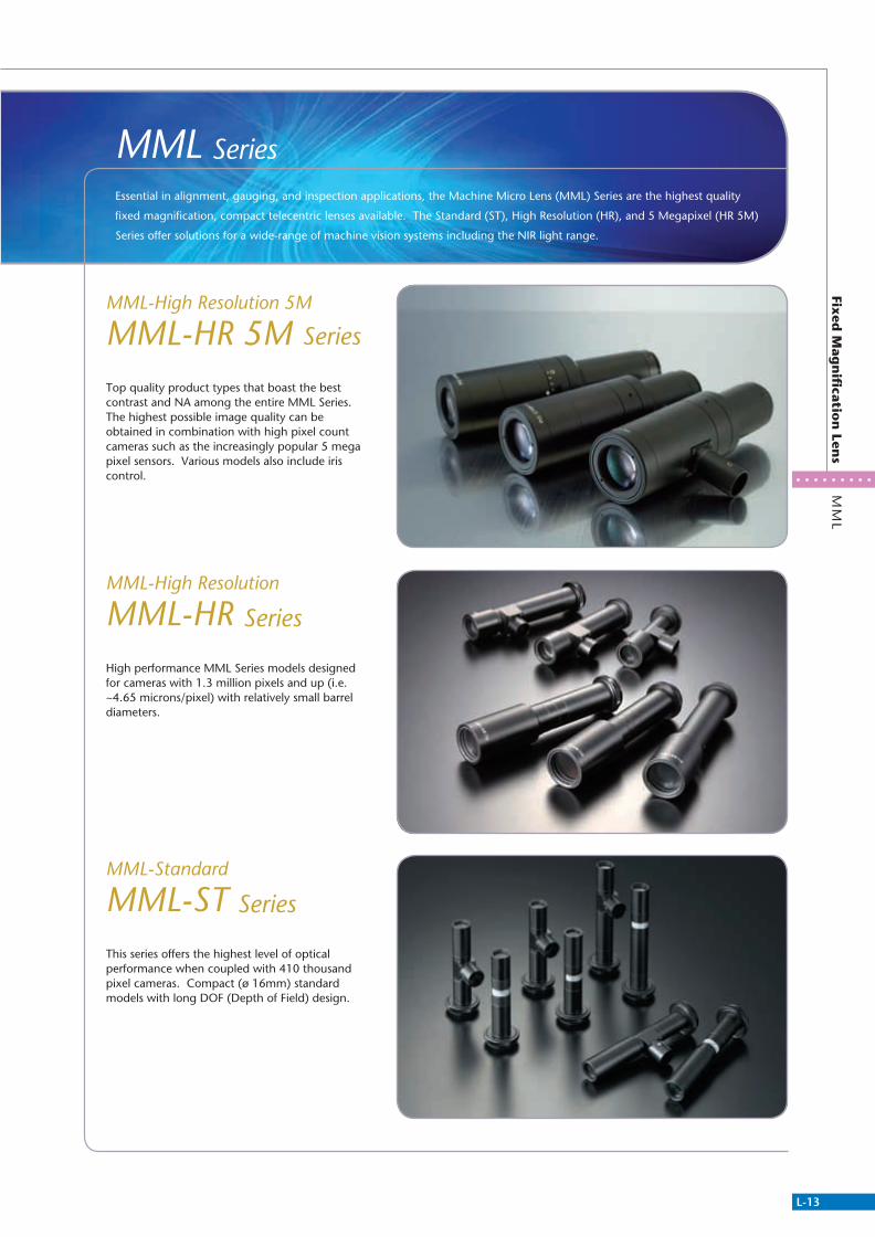
MML SeriesEssential in alignment, gauging, and inspection applications, the Machine Micro Lens (MML) Series are the highest quality
fixed magnification, compact telecentric lenses available. The Standard (ST), High Resolution (HR), and 5 Megapixel (HR 5M)
Series offer solutions for a wide-range of machine vision systems including the NIR light range.
MML-High Resolution
MML-HR Series
MML-High Resolution 5M
MML-HR 5M Series
MML-Standard
MML-ST Series
Top quality product types that boast the best contrast and NA among the entire MML Series.The highest possible image quality can beobtained in combination with high pixel count cameras such as the increasingly popular 5 mega pixel sensors. Various models also include iris control.
High performance MML Series models designed for cameras with 1.3 million pixels and up (i.e. ~4.65 microns/pixel) with relatively small barrel diameters.
This series offers the highest level of optical performance when coupled with 410 thousand pixel cameras. Compact (ø 16mm) standard models with long DOF (Depth of Field) design.
311766_MV_LensKatalog.indd 13 07.09.11 15:01

L-14
Telecentric Lens
MM
L Fixed
Mag
nifi catio
n Series
MM
L-HR
5M
Contrast improvement has enabled image recognition with greater emphasis on the black and white shading. By converting the resolution chart image to binary form and then graphing and comparing the brightness levels, the MML-HR greatly emphasizes the difference in brightness between black and white object features when compared to our prior Mega MML.
-1.00 0.00PERCENT
DISTOTION
+Y
1.00 -1.00 0.00PERCENT
DISTOTION
+Y
1.00
The pursuit of high resolution with no aberration has resulted in the elimination of image bending. This means that it is no longer necessary to consider distortion offsets.
Extremely Low Distortion High Contrast
MML-HR & MML-STConventional MML MML-HR & MML-STConventional MML
Provisions made to reduce coaxial illumination hot spots seen in low magnifi cation lenses
Equipped with a noise reduction filterCuts long wavelengths
MML03-HR65D 5M / MML03-HR110D 5M
Internal reflection light-scattering designMML-HR 5M (All models)
Conventional Design Lens MML-HR 5M Series
patent pending
Please note that although the lens is structured to suppress hot spots, hot spots will occur for mat surface work.
311766_MV_LensKatalog.indd 14 07.09.11 15:01

L-15
MM
L Fixed
Mag
nifi
cation
SeriesM
ML-H
R 5
M
ø34 Ring TypeMML
ø30 Ring TypeMML-ST / HR
Set Screw TypeMML-ST / HR
MORITEX provides customized responses to requests for modifications of mounts and special mounts.
For object recognition on a matte surface with coaxial illumination, only a small amount of light is reflected from the surface requiring the coaxial light intensity to be increased. When this is done, however, the brightness in the center of the image increases due to reflection in the coaxial illumination lensing. The ST and HR Series solve this problem through a hot spot reduction technique that vastly reduces the reflection from the lens. This improves the uniformity of coaxial illumination for even matte surfaces.
Below, OCR using coaxial illumination was performed on a rough, microcomputer chip surface. The MML-ST/HR brightness graph shows a reduction in the variation between the brightness in the center and periphery of the FOV which can also be seen in the sample images.
The MML HR/ST Series consist of three types of optical design focuses as well as for CCD camera compatibility.
Pixel size, resolution limitation frequency, F No relation
Design Concept
MML-STandard MML-High ResolutionFormat 2/3”Pixel Size 3.45µm
Format 1/2”Pixel Size 6.35µm
Format 2/3”Pixel Size 4.65µm
MML-High Resolution 5M
F N
o
5 50 100 150 2004030
25
20
15
10
5
0
35
30
25
20
15
10
5
0
Spatial Frequency [lp/mm]
Pixe
l Siz
e [µ
m]
Pixel Size [µm]F No
C Mount 3 Different Mount Types
Illumination Uniformity
MML-HR & MML-STConventional MML
CCD Camera: 5 million pixels, 3.45µm/pixelLens: Optical magnification 2x WD65 mmTest Chart : Resolution 5.563µm (resolving power 179.6 lp/mm)
Image Comparison for MML Series
Field of view 4.4mm
00.7
0.8
0.9
1
1.1
2 4 6 8 10 12 14
Co
ntr
ast
MML2-HR65D-5M
00.7
0.8
0.9
1
1.1
2 4 6 8 10 12 14
Co
ntr
ast
MML2-ST65D
00.7
0.8
0.9
1
1.1
2 4 6 8 10 12 14
Co
ntr
ast
MML2-HR65D
VGA Class 1.3Mega Class 5Mega Class
MML-ST Series MML-HR Series MML-HR 5M Series
311766_MV_LensKatalog.indd 15 07.09.11 15:01

L-16
Telecentric Lens
MM
L-HR
5M
MM
L Fixed
Mag
nifi
cation
Series
MML
MML Fixed Magnification Series
MML-High Resolution 5M Series
• Highest image quality model of the MMLs Series.
• Supports 5 million pixels (3.34μm/pixel) * Except for MML4-HR65DVI-5M
• Use of internal reflection light-scattering design and noise reduction filter for hot spot reduction
• Variable iris available for most models
• Very low distortion
High-resolution models that possess the best contrast and NA of all MML Series. Image acquisition with even higher image quality is realized by combining these lenses with cameras with a high number of pixels, especially emerging 5 megapixel sensors.
Model Magnification WD Resolution Depth Of Field NA Effective F No
Optical Distortion
Largest Compatible
CCD
Weight(g) Mount Product
Code
MML03-HR65D-5M 0.3x 65.1mm 15.7μm 6.2mm 0.021 7 0.002% 2/3” 202 C Mount A-3133
MML03-HR65-5M 0.3x 65.1mm 15.7μm 6.2mm 0.021 7 0.002% 2/3" 198 C Mount A-3134
MML05-HR65DVI-5M 0.5x 65.3mm 9.3μm~41μm 2.2mm~9.8mm 0.036~0.008 7~30.6 0.006% 2/3" 210 C Mount A-3137
MML05-HR65VI-5M 0.5x 65.3mm 9.3μm~41μm 2.2mm~9.8mm 0.036~0.008 7~30.6 0.006% 2/3" 210 C Mount A-3140
MML1-HR65DVI-5M 1x 65mm 4.7μm~19μm 0.56mm~2.2mm 0.071~0.018 7~28 0.028% 2/3" 140 C Mount A-3138
MML1-HR65VI-5M 1x 65mm 4.7μm~19μm 0.56mm~2.2mm 0.071~0.018 7~28 0.028% 2/3" 135 C Mount A-3141
MML2-HR65DVI-5M 2x 65mm 2.422μm~15.25μm 0.145mm~0.898mm 0.139~0.022 7.25~44.92 0.035% 2/3" 200 C Mount A-3139
MML2-HR65VI-5M 2x 65mm 2.422μm~15.25μm 0.145mm~0.898mm 0.139~0.022 7.25~44.92 0.035% 2/3" 190 C Mount A-3142
MML3-HR65DVI-5M 3x 65mm 2.1μm~10.5μm 0.085mm~0.42mm 0.157~0.032 9.6~47.5 0.004% 2/3" 280 C Mount A-3156
MML3-HR65VI-5M 3x 65mm 2.1μm~10.5μm 0.085mm~0.42mm 0.157~0.032 9.6~47.5 0.004% 2/3" 275 C Mount A-3158
MML4-HR65DVI-5M 4x 65mm 2μm~8.2μm 0.06mm~0.24mm 0.167~0.041 12.1~48.6 -0.021% 2/3" 290 C Mount A-3157
MML4-HR65VI-5M 4x 65mm 2μm~8.2μm 0.06mm~0.24mm 0.167~0.041 12.1~48.6 -0.021% 2/3" 285 C Mount A-3159
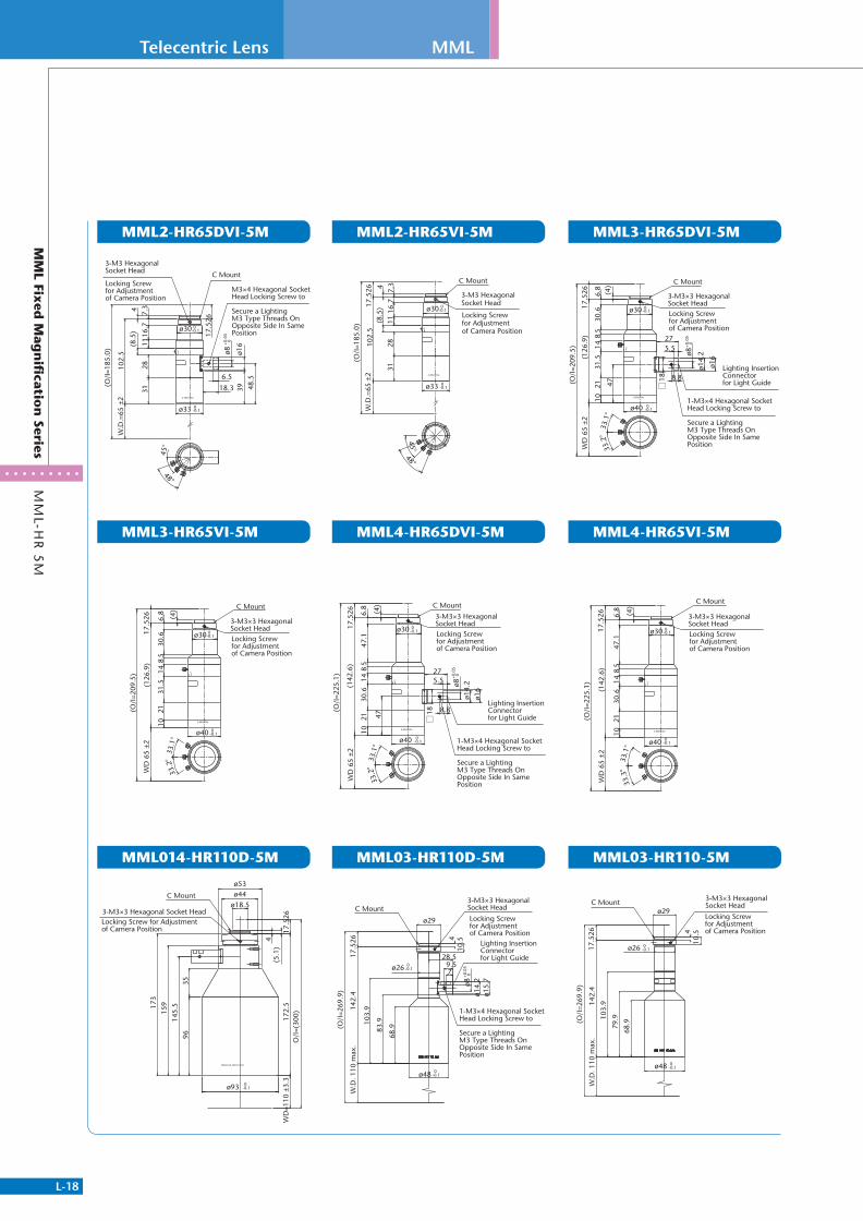
MML014-HR110D-5M 0.14x 110mm 19.2μm 16.4mm 0.018 4 0.001% 2/3" 730 C Mount A-3165
MML03-HR110D-5M 0.3x 110mm 15.7μm 6.2mm 0.021 7 0.012% 2/3" 212 C Mount A-3135
MML03-HR110-5M 0.3x 110mm 15.7μm 6.2mm 0.021 7 0.012% 2/3" 209 C Mount A-3136
NEW MML014-HR110D-5M
311766_MV_LensKatalog.indd 16 07.09.11 15:01
L-17
MM
L Fixed
Mag
nifi
cation
SeriesM
ML-H
R 5
M
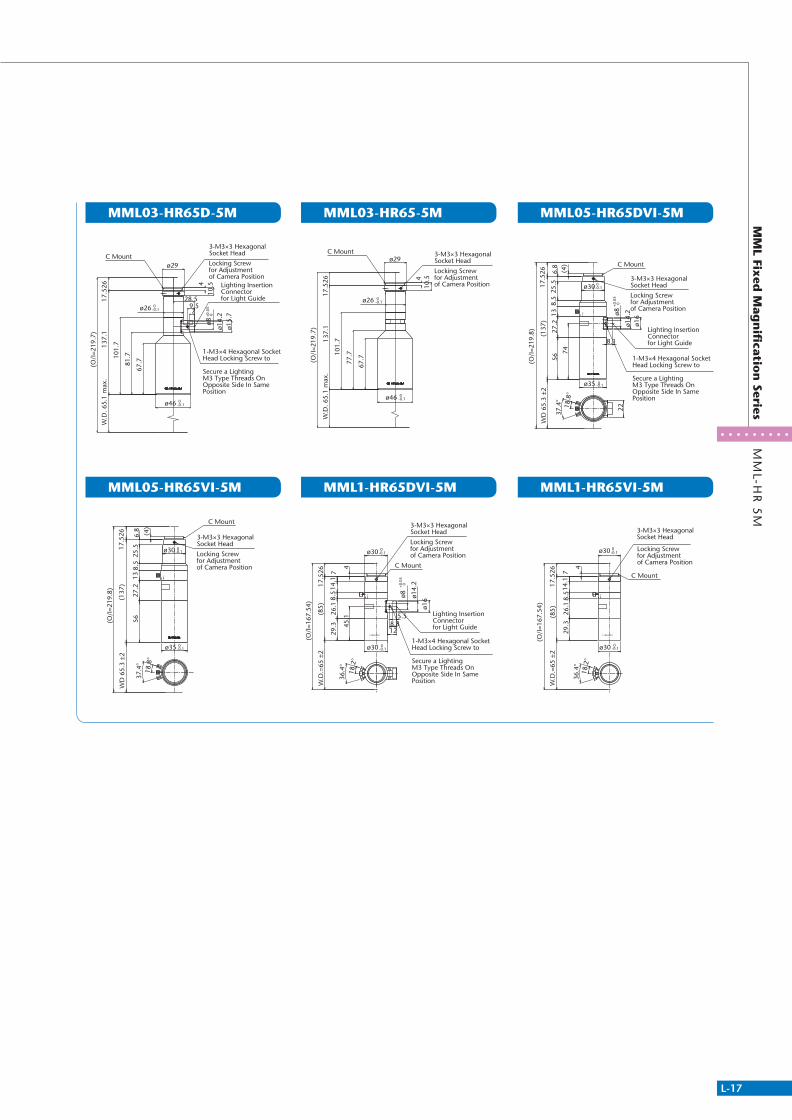
MML03-HR65D-5M
MML05-HR65VI-5M
MML05-HR65DVI-5M
MML1-HR65VI-5M
MML03-HR65-5M
MML1-HR65DVI-5M
7
ø8+0
.05
0
ø14.
2
28.517.5
2613
7.1
W.D
. 65.
1 m
ax.
(O/I
=219
.7)
81.7
ø29
ø26 0-0.1
9.5
ø15.
7
4
101.
7
67.7
10.5
ø46 0-0.1
Lighting Insertion Connector for Light Guide
Locking Screw for Adjustment of Camera Position
3-M3×3 HexagonalSocket Head C Mount
1-M3×4 Hexagonal Socket Head Locking Screw to
Secure a LightingM3 Type Threads On Opposite Side In Same Position
17.5
2613
7.1
W.D
. 65.
1 m
ax.
(O/I
=219
.7)
ø29
ø26 0-0.1
4
101.
7
67.7
10.5
77.7
ø46 0-0.1
C Mount
Locking Screw for Adjustment of Camera Position
3-M3×3 HexagonalSocket Head
ø16
ø14.
2ø8+0
.05
0
74
5627
.26.
8
(137
)W
D 6
5.3
±217
.526 (4
)
(O/I
=219
.8)
ø30 0-0.1
18.8
°
37.4
°
ø35 0-0.1
25.5
138.
5
8.1
22
C Mount
Locking Screw for Adjustment of Camera Position
3-M3×3 HexagonalSocket Head
Lighting Insertion Connector for Light Guide
1-M3×4 Hexagonal Socket Head Locking Screw to
Secure a LightingM3 Type Threads On Opposite Side In Same Position
5627
.26.
8
(137
)W
D 6
5.3
±217
.526 (4
)
(O/I
=219
.8)
ø35 0-0.1
ø30 0-0.1
18.8
°
37.4
°25
.513
8.5
C Mount
Locking Screw for Adjustment of Camera Position
3-M3×3 HexagonalSocket Head
Lighting Insertion Connector for Light Guide
W.D
.=65
±2
17.5
26(8
5)
45.1 5.5
714
.18.
5
ø30 0-0.1
36.4
°18
.2°
4 C Mount
(O/I
=167
.54)
ø30 0-0.1
ø8+0
.05
0
ø14.
2
ø16
29.3
26.1
8.812
Locking Screw for Adjustment of Camera Position
3-M3×3 HexagonalSocket Head
1-M3×4 Hexagonal Socket Head Locking Screw to
Secure a LightingM3 Type Threads On Opposite Side In Same Position
17.5
26W
.D.=
65 ±
2(8
5)
714
.18.
5
ø30 0-0.1
36.4
°18
.2°
4
(O/I
=167
.54)
ø30 0-0.1
29.3
26.1
C Mount
Locking Screw for Adjustment of Camera Position
3-M3×3 HexagonalSocket Head
311766_MV_LensKatalog.indd 17 07.09.11 15:01
L-18
Telecentric Lens MML
MM
L-HR
5M
MM
L Fixed
Mag
nifi
cation
Series
MML2-HR65DVI-5M
MML3-HR65VI-5M
MML014-HR110D-5M
MML3-HR65DVI-5M
MML4-HR65VI-5M
MML03-HR110-5M
MML2-HR65VI-5M
MML4-HR65DVI-5M
MML03-HR110D-5M
45°
7.3
11
ø30 0-0.1
C Mount
416
.7
102.
5
17.5
26
(8.5
)
2831
6.5
18.3
ø8+0
.05
0
39ø1
6
ø33 0-0.1
48.5
W.D
.=65
±2
48°
(O/I
=185
.0)
Locking Screw for Adjustment of Camera Position
3-M3 HexagonalSocket Head
M3×4 Hexagonal Socket Head Locking Screw to
Secure a LightingM3 Type Threads On Opposite Side In Same Position
45°
7.3
11
ø30 0-0.1
416
.7
102.
517
.526
(8.5
)
2831
(O/I
=185
.0)
ø33 0-0.1
W.D
.=65
±2
48°
C Mount
Locking Screw for Adjustment of Camera Position
3-M3 HexagonalSocket Head
(O/I
=209
.5)
(4)
17.5
26W
D 6
5 ±2
(126
.9)
6.8
30.6 ø30 0
-0.1
ø40 0-0.1
47
58
1431
.521
10
C Mount
27
8.8
5.5
ø8+0
.05
0
ø14.
2
ø16
33.1
°33
.2°
18
Locking Screw for Adjustment of Camera Position
3-M3×3 HexagonalSocket Head
Lighting Insertion Connector for Light Guide
1-M3×4 Hexagonal Socket Head Locking Screw to
Secure a LightingM3 Type Threads On Opposite Side In Same Position
(O/I
=209
.5)
WD
65
±2(1
26.9
)
ø40 0-0.1
1431
.521
1033
.1°
33.2
°(4
)
17.5
26 6.8
30.6 ø30 0
-0.1
58
C Mount
Locking Screw for Adjustment of Camera Position
3-M3×3 HexagonalSocket Head
(142
.6)
47.1
ø40 0-0.1
18
ø16
ø14.
2ø8+0
.05
0
5.5
8.8
47
58
1430
.621
10
27
33.1
°33
.2°
C Mount
ø30 0-0.1
(4)
6.8
17.5
26
(O/I
=225
.1)
WD
65
±2
Lighting Insertion Connector for Light Guide
Locking Screw for Adjustment of Camera Position
3-M3×3 HexagonalSocket Head
1-M3×4 Hexagonal Socket Head Locking Screw to
Secure a LightingM3 Type Threads On Opposite Side In Same Position
(O/I
=225
.1)
WD
65
±2(1
42.6
)
ø40 0-0.1
58
1430
.621
1033
.1°
33.3
°(4
)
17.5
26 6.8
47.1
ø30 0-0.1
C Mount
Locking Screw for Adjustment of Camera Position
3-M3×3 HexagonalSocket Head
4
ø18.5
(5.1
)17
2.5
17.5
26
159
ø53ø44
96
WD
=110
±3.
3
ø93 0-0.1
O/I
=(30
0)
173
145.
535
C Mount
Locking Screw for Adjustment of Camera Position
3-M3×3 Hexagonal Socket Head
ø8+0
.05
0
ø14.
2
7
28.517.5
2614
2.4
W.D
. 110
max
.
83.910
3.9
(O/I
=269
.9)
ø29
410
.5
ø26 0-0.1
ø15.
7
ø48 0-0.1
9.5
68.9
Lighting Insertion Connector for Light Guide
C MountLocking Screw for Adjustment of Camera Position
3-M3×3 HexagonalSocket Head
1-M3×4 Hexagonal Socket Head Locking Screw to
Secure a LightingM3 Type Threads On Opposite Side In Same Position
17.5
2614
2.4
W.D
. 110
max
.
103.
9
(O/I
=269
.9)
ø29
410
.5
ø26 0-0.1
ø48 0-0.1
68.979
.9
C Mount
Locking Screw for Adjustment of Camera Position
3-M3×3 HexagonalSocket Head
311766_MV_LensKatalog.indd 18 07.09.11 15:01

L-19
MM
L-HR
5M
MM
L Fixed
Mag
nifi
cation
Series
311766_MV_LensKatalog.indd 19 07.09.11 15:01

L-20
Telecentric Lens
MM
L-HR
MM
L Fixed
Mag
nifi
cation
Series
MML
MML-High Resolution
MML-HR Series
• Supports mega pixel CCDs, 1.3 million pixels or greater
• High resolution throughout the entire field of view
• High NA and contrast
• Most models compatible with 2/3" or smaller CCD elements
The MML-HR Series consists of highly versatile models that support mega pixel cameras with 1.3 million pixels or more (4.65um/pixel).
The entire lineup features a high resolution and contrast design that realizes amazingly high image quality which cannot be shown by numbers alone. This series provides true imaging power in high end inspections and alignment applications.
WD65mm
Model Magnification WD Resolution Depth of Field NA Effective F NoOptical
DistortionLargest Compatible
CCDWeight Mount
Product Code
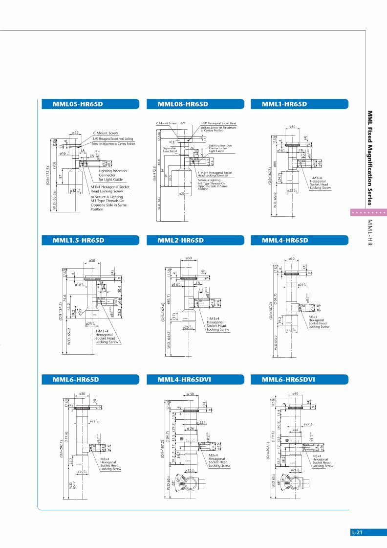
MML05-HR65D 0.5x 65mm 12.8μm 3.04mm 0.026 9.5 -0.001% or less 2/3" 75g C Mount A-3029MML08-HR65D 0.8x 65mm 8.4μm 1.2mm 0.04 9.9 0.029% 2/3" 64g C Mount A-3128MML1-HR65D 1.0x 65mm 7.5μm 0.88mm 0.045 11 0.043% 2/3" 58g C Mount A-3031MML1.5-HR65D 1.5x 65mm 5.4μm 0.42mm 0.063 12 -0.003% 1/2" 53g C Mount A-3032MML2-HR65D 2.0x 65mm 4.5μm 0.27mm 0.074 13.5 0.013% 2/3" 52g C Mount A-3033MML4-HR65D 4.0x 65mm 3μm 0.09mm 0.112 17.9 -0.060% 2/3" 94g C Mount A-3034MML6-HR65D 6.0x 65mm 3μm 0.06mm 0.112 26.7 -0.110% 2/3" 102g C Mount A-3035MML4-HR65DVI 4.0x 65mm 3~13.3μm 0.09~ 0.53mm 0.112 17.9~79.2 0.053% 2/3" 95g C Mount A-3094MML6-HR65DVI 6.0x 65mm 3~13.9μm 0.06~ 0.58mm 0.112 26.7~124 0.005% 2/3" 102g C Mount A-3095
* Resolution values indicate the theoretical resolution at a wavelength of 550nm.* Depth of field is calculated assuming a horizontal 240TV resolution using a 1/2 CCD camera. (Permissible circle of confusion on the image-formation side: 40μm)
311766_MV_LensKatalog.indd 20 07.09.11 15:01
L-21
MM
L Fixed
Mag
nifi
cation
SeriesM
ML-H
R
MML05-HR65D
MML1.5-HR65D
MML6-HR65D
MML1-HR65D
MML4-HR65D
MML6-HR65DVI
MML08-HR65D
MML2-HR65D
MML4-HR65DVI
Screw for Adjustment of Camera Position
Lighting Insertion Connector for Light Guide
M3×4 Hexagonal Socket Head Locking Screw
3-M3 Hexagonal Socket Head Locking
C Mount Screw
W.D
. 65.
3±2
(O/I
=172
.8) (90)
37
ø16 0-0.1
17.52
6 411
to Secure A LightingM3 Type Threads On Opposite Side in Same Position
ø32 0-0.1
7.518
ø8+0
.05
0
ø29
ø14.2
ø15.7
*** **##
ø25
17.5
26W
.D. 6
5±2
4
45°
ø30
(4)
9
74.6
(O/I
157
.2)
19.2
43.2
ø16 0-0.1
0-0.1
1-M3×4 Hexagonal Socket Head Locking Screw
23.2
18107.5
ø14.
2ø1
630
.4
ø8+0
.015
0
(4)
9
ø22
ø25
ø30
0-0.1
0-0.1
4(1
19.6
)17
.526
(O/I
=202
.1)
W.D
.65
±222
.7 M3×4 Hexagonal Socket Head Locking Screw
ø16
ø14.
2
ø8+0
.05
0
ø25
ø30
ø16
(O/I
=162
.5)
W.D
. 65±
217
.526
(24.
7)(8
0)
9(4
)
4
0-0.1
0-0.1
1-M3×4 Hexagonal Socket Head Locking Screw
ø14.
2
ø16
187.5
ø8+0
.015
0
W.D
65±
217
.526
ø22
ø25
4
ø30
0-0.1
0-0.1
(104
.7)
(O/I
=187
.2)
9
(4)
19.2 M3×4
Hexagonal Socket Head Locking Screw
ø8+0
.05
0
ø16
ø14.
2
0-0.1
+0.0
5 0
0-0.1
ø26
ø30
38.2(O
/I=2
02.1
) (119
.5)
22.7
38°
W.D
65±
2
68°
13.4
(40.
9)7
1713
.5
17.5
26
4
M3×4 Hexagonal Socket Head Locking Screw
ø16
9
(4)
ø14.
2
ø25
ø22
ø8
Separable Lens Barrel
Locking Screw for Adjustment of Camera Position
3-M3 Hexagonal Socket Head C Mount Screw
W.D
. 65±
2
ø16
ø25
59
114
ø29
(O/I
=172
.3) 89
.817
.526
0-0.1
0-0.1
7.5
ø8
ø14.
2
39
10
ø16
26
30.5
Lighting Insertion Connector for Light Guide
1-M3×4 Hexagonal Socket Head Locking Screw to
Secure a LightingM3 Type Threads On Opposite Side In Same Position
*** **##
0+0.
05
18
ø8+0
.015
0
ø25
17.5
26W
.D. 6
5±2
(4)
ø16 0-0.1
0-0.1
ø30
(O/I
=162
.6)
(17)
(80.
1)
9
4
1-M3×4 Hexagonal Socket Head Locking Screw
ø16
ø14.
2
7.5
M3×4 Hexagonal Socket Head Locking Screw
25 0-0.1
19.2
38°
W.D
65
±2
68°
13.5
(104
.7)
(O/I
=187
.2)
717
(29.
5)13
.4
26
17.5
26
4
30
ø+0
.05
0
22 0-0.1
1614.2
(4)
9
ø
34.7
ø
ø
8
ø
øø
311766_MV_LensKatalog.indd 21 07.09.11 15:01

L-22
Telecentric Lens
MM
L Fixed
Mag
nifi
cation
Series
MML
MM
L-HR
MML05-HR65
MML2-HR65
MML08-HR65
MML4-HR65
MML1-HR65
MML6-HR65
MML1.5-HR65
MML-PL25HR • Dedicated 90˚ prism for MML-HR. See page L-40 for details.
for Adjustment of Camera Position
3-M3 Hexagonal Socket Head Locking Screw
C Mount Screw
W.D
. 65.
3±2
(O/I
=172
.8)
(90)
37
ø16 0-0.1
17.52
6 411
ø32 0-0.1
ø29
*****
##
ø25
17.5
26W
.D. 6
5±2
(4)
ø16 0-0.1
0-0.1
ø30
(O/I
=162
.6)
(17)
(80.
1)
9
4
Separable Lens Barrel
for Adjustment of Camera Position
3-M3×3 Hexagonal Socket Head Locking Screw
C Mount Screw
30.5
W.D
. 65±
2
ø16
ø25
59
114
ø29
(O/I
=172
.3)
89.8
17.5
26
## *****
0-0.1
0-0.1
W.D
65±
217
.526
ø22
ø25
4
ø30
0-0.1
0-0.1
(104
.7)
(O/I
=187
.2)
9
(4)
19.2
ø25
ø30
ø16
(O/I
=162
.5)
W.D
. 65±
217
.526
(24.
7)(8
0)
9(4
)
4
0-0.1
0-0.1
(4)
9
ø22
ø25
ø30
0-0.1
0-0.1
4(1
19.6
)17
.526
(O/I
=202
.1)
W.D
. 65±
222
.7
ø25
17.5
26W
.D. 6
5±2
4
45°
ø30
(4)
9
74.6
(O/I
157
.2)
19.2
43.2 (ø15.6)9
6
ø16 0-0.1
0-0.1
Model Magnification WD Resolution Depth of Field NA Effective F NoOptical
DistortionLargest Compatible
CCDWeight Mount
Product Code
MML05-HR65 0.5x 65mm 12.8μm 3.04mm 0.026 9.5 -0.001% 2/3" 70g C Mount A-3044MML08-HR65 0.8x 65mm 8.4μm 1.2mm 0.04 9.9 0.029% 2/3" 60g C Mount A-3129MML1-HR65 1.0x 65mm 7.5μm 0.88mm 0.045 11 0.043% 2/3" 50g C Mount A-3045MML1.5-HR65 1.5x 65mm 5.4μm 0.42mm 0.063 12 -0.003% 1/2" 46g C Mount A-3046MML2-HR65 2.0x 65mm 4.5μm 0.27mm 0.074 13.5 0.013% 2/3" 46g C Mount A-3047MML4-HR65 4.0x 65mm 3μm 0.09mm 0.112 17.9 -0.060% 2/3" 86g C Mount A-3048MML6-HR65 6.0x 65mm 3μm 0.06mm 0.112 26.7 -0.110% 2/3" 94g C Mount A-3049
* Resolution values indicate the theoretical resolution at a wavelength of 550nm.* Depth of field is calculated assuming a horizontal 240TV resolution using a 1/2" CCD camera. (Permissible circle of confusion on the image-formation side: 40μm)
311766_MV_LensKatalog.indd 22 07.09.11 15:01
L-23
MM
L Fixed
Mag
nifi
cation
SeriesM
ML-H
R
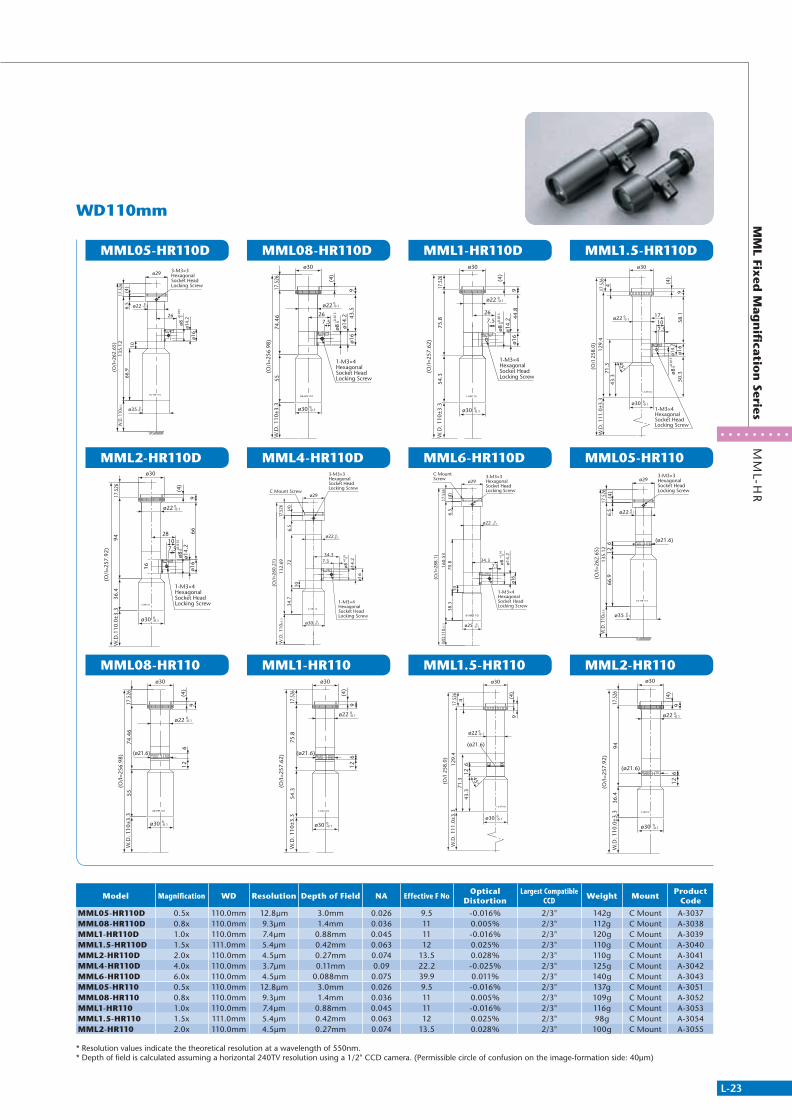
MML05-HR110D
MML2-HR110D
MML08-HR110
MML08-HR110D
MML4-HR110D
MML1-HR110
MML1-HR110D
MML6-HR110D
MML1.5-HR110
MML1.5-HR110D
MML05-HR110
MML2-HR110
WD110mm
3-M3×3 Hexagonal Socket Head Locking Screw
26
(O/I
=262
.65)
17.5
26W
.D. 1
10±5
.513
5.12
(4)
6.5
66.9
10
ø35
ø22
ø29
ø8 ø14.
2ø1
6
+0.0
15 0
0-0.1
0-0.1
9436
.4
(O/I
=257
.92)
9
(4)
17.5
26
ø30
W.D
.110
.0±3
.3
ø22 0-0.1
ø30 0-0.1
1-M3×4 Hexagonal Socket Head Locking Screw
ø8+0
.015
0
28107.5
66
16
ø14.
2ø1
612
6
(ø21.6)
(4)
917.5
2674
.46
W.D
. 110
±3.3
(O/I
=256
.98)
55
ø30
ø30
ø22 0-0.1
0-0.1
(4)
917.5
2674
.46
W.D
. 110
±3.3
(O/I
=256
.98)
55ø30
ø30
ø22 0-0.1
0-0.1
1-M3×4 Hexagonal Socket Head Locking Screw
7.526
ø8 ø14.
2ø1
643
.5
+0.0
150
3-M3×3Hexagonal Socket Head Locking Screw
ø14.
2
ø16
ø8
132.
69
10
72
(O/I
=260
.21)
ø30
W.D
. 110
±3.3
34.7
C Mount Screw
6.5
(4)
17.5
26
ø22
34.37.3
ø29
4-HR110
FG MML
MO
0-0.1
+0.0
30
0-0.1
1-M3×4 Hexagonal Socket Head Locking Screw
126
(ø21.6)
ø22
ø30
W.D
. 110
±3.3
ø30
9
(4)
75.8
54.3
(O/I
=257
.62)
17.5
26
0-0.1
0-0.1
1-M3×4 Hexagonal Socket Head Locking Screw
ø22
ø30
W.D
. 110
±3.3
ø30
9
(4)
75.8
54.3
(O/I
=257
.62)
17.5
26
267.5
ø14.
2ø1
644
.8
ø8+0
.015
0
0-0.1
0-0.1
3-M3×3 Hexagonal Socket Head Locking Screw
C Mount Screw
10
ø25 0-0.1
W.D
.110
±3.3
38.3
(O/I
=288
.1)
70.8
160.
53
7.334.3
ø14.
2ø8
+0.0
3 0
ø22 0-0.1
ø29
17.5
266.
5(4
)
ø16
6-HR110
FG MML
MO
1-M3×4 Hexagonal Socket Head Locking Screw
W.D
. 111
.0±3
.312
9.4
17.5
264
(O/I
258
.0)
(4)
9
45°
ø22
ø30
ø30
71.3
43.3
(ø21.6)
126
0-0.1
0-0.1
W.D
. 111
.0±3
.312
9.4
17.5
264
(O/I
258
.0)
(4)
9
45°
ø22
ø30
ø30
71.3
43.3
0-0.1
0-0.1
1-M3×4 Hexagonal Socket Head Locking Screw
ø14.
2ø1
658
.150
.3
7.510
17
ø8+0
.015
0
(ø21.6)
ø29
66.9
135.
12(O
/I=2
62.6
5)W
.D. 1
10±3
.3
6.5
126
(4)
17.5
26
3-M3×3 Hexagonal Socket Head Locking Screw
0-0.1
0-0.1ø22
ø35
(ø21.6)
612
9436
.4
(O/I
=257
.92)
9
(4)
17.5
26
ø30
W.D
. 110
.0±3
.3
ø22 0-0.1
ø30 0-0.1
Model Magnification WD Resolution Depth of Field NA Effective F NoOptical
DistortionLargest Compatible
CCDWeight Mount
Product Code
MML05-HR110D 0.5x 110.0mm 12.8μm 3.0mm 0.026 9.5 -0.016% 2/3" 142g C Mount A-3037MML08-HR110D 0.8x 110.0mm 9.3μm 1.4mm 0.036 11 0.005% 2/3" 112g C Mount A-3038MML1-HR110D 1.0x 110.0mm 7.4μm 0.88mm 0.045 11 -0.016% 2/3" 120g C Mount A-3039MML1.5-HR110D 1.5x 111.0mm 5.4μm 0.42mm 0.063 12 0.025% 2/3" 110g C Mount A-3040MML2-HR110D 2.0x 110.0mm 4.5μm 0.27mm 0.074 13.5 0.028% 2/3" 110g C Mount A-3041MML4-HR110D 4.0x 110.0mm 3.7μm 0.11mm 0.09 22.2 -0.025% 2/3" 125g C Mount A-3042MML6-HR110D 6.0x 110.0mm 4.5μm 0.088mm 0.075 39.9 0.011% 2/3" 140g C Mount A-3043MML05-HR110 0.5x 110.0mm 12.8μm 3.0mm 0.026 9.5 -0.016% 2/3" 137g C Mount A-3051MML08-HR110 0.8x 110.0mm 9.3μm 1.4mm 0.036 11 0.005% 2/3" 109g C Mount A-3052MML1-HR110 1.0x 110.0mm 7.4μm 0.88mm 0.045 11 -0.016% 2/3" 116g C Mount A-3053MML1.5-HR110 1.5x 111.0mm 5.4μm 0.42mm 0.063 12 0.025% 2/3" 98g C Mount A-3054MML2-HR110 2.0x 110.0mm 4.5μm 0.27mm 0.074 13.5 0.028% 2/3" 100g C Mount A-3055
* Resolution values indicate the theoretical resolution at a wavelength of 550nm.* Depth of field is calculated assuming a horizontal 240TV resolution using a 1/2" CCD camera. (Permissible circle of confusion on the image-formation side: 40μm)
311766_MV_LensKatalog.indd 23 07.09.11 15:01
L-24
Telecentric Lens
MM
L-ST
MM
L Fixed
Mag
nifi
cation
Series
MML
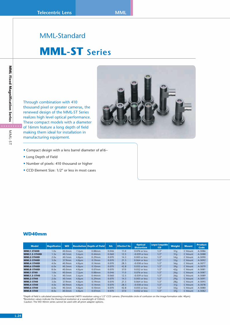
MML-Standard
MML-ST Series
• Compact design with a lens barrel diameter of ø16~
• Long Depth of Field
• Number of pixels: 410 thousand or higher
• CCD Element Size: 1/2" or less in most cases
Through combination with 410 thousand pixel or greater cameras, the renewed design of the MML-ST Series realizes high level optical performance. These compact models with a diameter of 16mm feature a long depth of field making them ideal for installation in manufacturing equipment.
WD40mm
Model Magnification WD Resolution Depth of Field NA Effective F NoOptical
DistortionLargest Compatible
CCDWeight Mount
Product Code
MML1-ST40D 1.0x 40.0mm 7.2μm 0.88mm 0.046 11.0 0.076 or less 1/2" 31g C Mount A-3086MML1.5-ST40D 1.5x 40.1mm 5.6μm 0.44mm 0.060 12.5 -0.039 or less 1/2" 31g C Mount A-3088MML2-ST40D 2.0x 40.1mm 4.8μm 0.29mm 0.070 14.3 0.003 or less 1/2" 34g C Mount A-3090MML3-ST40D 3.0x 37.9mm 4.8μm 0.19mm 0.070 21.3 0.064 or less 1/2" 33g C Mount A-3092MML4-ST40D 4.0x 40.9mm 4.8μm 0.14mm 0.070 28.5 -0.038 or less 1/2" 36g C Mount A-3077MML6-ST40D 6.0x 40.3mm 4.8μm 0.10mm 0.070 42.8 0.035 or less 1/2" 39g C Mount A-3079MML8-ST40D 8.0x 40.0mm 4.8μm 0.07mm 0.070 57.0 0.032 or less 1/2" 42g C Mount A-3081MML1-ST40 1.0x 40.0mm 7.2μm 0.88mm 0.046 11.0 0.076 or less 1/2" 26g C Mount A-3087MML1.5-ST40 1.5x 40.1mm 5.6μm 0.44mm 0.060 12.5 -0.039 or less 1/2" 26g C Mount A-3089MML2-ST40 2.0x 40.1mm 4.8μm 0.29mm 0.070 14.3 0.003 or less 1/2" 29g C Mount A-3091MML3-ST40 3.0x 37.9mm 4.8μm 0.19mm 0.070 21.3 0.064 or less 1/2" 28g C Mount A-3093MML4-ST40 4.0x 40.9mm 4.8μm 0.14mm 0.070 28.5 -0.038 or less 1/2" 31g C Mount A-3078MML6-ST40 6.0x 40.3mm 4.8μm 0.10mm 0.070 42.8 0.035 or less 1/2" 35g C Mount A-3080MML8-ST40 8.0x 40.0mm 4.8μm 0.07mm 0.070 57.0 0.032 or less 1/2" 37g C Mount A-3082
*Depth of field is calculated assuming a horizontal 240TV resolution using a 1/2" CCD camera. (Permissible circle of confusion on the image-formation side: 40μm)*Resolution values indicate the theoretical resolution at a wavelength of 550nm. Caution: The WD 40mm series cannot be used with all prism adapter options.
311766_MV_LensKatalog.indd 24 07.09.11 15:01

L-25
MM
L-ST
MM
L Fixed
Mag
nifi
cation
Series
MML1-ST40D
MML4-ST40D
MML1-ST40
MML4-ST40
MML1.5-ST40D
MML6-ST40D
MML1.5-ST40
MML6-ST40
MML2-ST40D
MML8-ST40D
MML2-ST40
MML8-ST40
MML3-ST40D
MML3-ST40
17.2
(O/I
=105
)
ø29
47.5
W.D
. 40±
1.2
17.5
26
4
26
to Secure a LightingM3 Type Threads on Opposite Side in Same Position
M3×4 Hexagonal Socket Head Locking Screw
C Mount Screw
for Adjustment of Camera Position
Lighting Insertion Connector for Light Guide
ø16
3-M3 Hexagonal Socket Head Locking Screw
## *** **
ø16 0-0.1
ø29
1/2"CCD
C Mount Screw3-M3×3 Hexagonal Socket Head Locking Screw
7.5ø16
18
1-M3×4 Hexagonal Socket Head Locking Screw
W.D
. 40.
9±2
(O/I
=103
.9)
(45.
5)17
.526
ø8 ø14.
2
ø16
10.6
4
11
+0.0
5 0
0-0.1
for Adjustment of Camera Position
C Mount Screw3-M3 Hexagonal Socket Head Locking Screw
W.D
. 40±
1.2
47.5
(O/I
=105
)
17.5
26
40.5
4
ø29
ø16 0-0.1
## *****
1/2"CCD
3-M3×3 Hexagonal Socket Head Locking Screw
C Mount Screwø29
17.5
26
ø16
(45.
5)W
.D. 4
0.9±
2
(O/I
= 10
3.9)
ø16
411
0-0.1
0-0.1
M3×4 Hexagonal Socket Head Locking Screw
Lighting Insertion Connector for Light Guide
C Mount Screw
for Adjustment of Camera Position
3-M3 Hexagonal Socket Head Locking Screw
ø16
W.D
. 40.
1±1.
2(4
7.4)
(O/I
=105
.1)
17.5
26
14
4
11
M3 Type Threads on Opposite Side in Same Position
to Secure a Lighting
26
7.5
ø14.
2
ø16
ø8+0
.05
0
ø29
## *** **
0-0.1
1-M3×4 Hexagonal Socket Head Locking Screw
1/2"CCD
3-M3×3 Hexagonal Socket Head Locking Screw
C Mount Screw
ø16
18
7.5
ø29
(O/I
=117
.5)
17.5
26(5
9.6)
W.D
. 40.
3±2
ø8ø1
4.2
ø16
10.6
4
11
+0.0
5 0
0-0.1
for Adjustment of Camera Position
C Mount Screw3-M3 Hexagonal Socket Head Locking Screw
W.D
. 40.
1±1.
2(4
7.4)
17.5
26
(O/I
=105
.1)
114
ø16
ø29
*****##
0-0.1
1/2"CCD
C Mount Screw
3-M3×3 Hexagonal Socket Head Locking Screw
ø29
ø16
ø16
(O/I
= 11
7.5)
(59.
6)17
.526
W.D
. 40.
3±2
114
0-0.1
0-0.1
11.5
31.5
(O/I
=96.
1)
ø29
(38.
5)W
.D. 4
0.1±
1.2
17.5
26
C Mount Screw
26M3×4 Hexagonal Socket Head Locking Screw
to Secure a LightingM3 Type Threads on Opposite Side in Same Position
for Adjustment of Camera Position
Lighting Insertion Connector for Light Guide
ø16
7.5
ø8
ø16
ø14.
2
3-M3 Hexagonal Socket Head Locking Screw
## *** **
0-0.1
+0.0
50
(O/I
=131
.3)
17.5
26(7
3.8)
W.D
. 40±
2
4
11
ø8
ø14.
2
ø16
10.6
ø16
ø29
7.5
1/2"CCD
C Mount Screw3-M3×3 Hexagonal Socket Head Locking Screw
1-M3×4 Hexagonal Socket Head Locking Screw
+0.0
5 0
0-0.1
C Mount Screw
for Adjustment of Camera Position
3-M3 Hexagonal Socket Head Locking Screw
W.D
. 40.
1±1.
2(3
8.5)
(O/I
=96.
1)
17.5
26
31.5
16.5
6
ø16
## *****
ø29
0-0.1
ø16
ø16
ø29
1/2"CCD
C Mount Screw3-M3×3 Hexagonal Socket Head Locking Screw
(O/I
= 13
1.3)
(73.
8)17
.526
W.D
. 40±
2
411
0-0.1
0-0.1
C Mount Screw
M3×4 Hexagonal Socket Head Locking Screw
for Adjustment of Camera Position
Lighting Insertion Connector for Light Guide
3-M3 Hexagonal Socket Head Locking Screw
W.D
. 37.
9±1
.2(5
1.5)
17.5
26
(O/I
=106
.9)
M3 Type Threads on Opposite Side in Same Position
to Secure a Lighting
31.5
11.5
7.5
26
ø8
ø29
ø16
ø14.
2
ø16
## *****
0-0.1
+0.
05 0
ø16
17.5
26
ø29
(O/I
=106
.9)
W.D
. 37.
9±1.
2(5
1.5)
6
31.5
16.5
C Mount Screw
for Adjustment of Camera Position
3-M3 Hexagonal Socket Head Locking Screw
*****##
0-0.1
311766_MV_LensKatalog.indd 25 07.09.11 15:01
L-26
Telecentric Lens MML
MM
L-ST
MM
L Fixed
Mag
nifi
cation
Series
MML08-ST65D
MML2-ST65DS
MML6-ST65D
MML1-ST65D
MML3-ST65DS
MML6-ST65DS
MML1.5-ST65D
MML4-ST65D
MML8-ST65DS
MML2-ST65D
MML4-ST65DS
WD65mm
C Mount Screw
3-M3 Hexagonal Socket Head Locking Screw
M3×4 Hexagonal Socket Head Locking Screw
ø16
ø29
17.5
26
4
ø16
26
(89.
8)
39
(O/I
=172
.3)
ø18
W.D
. 65
±2 0-0.1
0-0.1
3-M3×3 Hexagonal Socket Head Locking Screw
1-M3×4 Hexagonal Socket Head Locking Screw
C Mount Screw
17.5
26
ø29
ø16
61.5
18107.5
(O/I
=144
.06)
ø8ø1
4.2
1118
.4ø1
620
.1
WD
.65±
2
7(4
)
+0.0
15 0 0
-0.1
ø16 0-0.1
17.5
26
4
(118
.5)
(O/I
=201
.05)
(4)
9
ø16
ø30
0-0.1
ø16 0-0.1
W.D
. 65±
2
ø14.
2
ø8+0
.02
0
1-M3×4 Hexagonal Socket Head Locking Screw
ø16
W.D
. 65±
2(8
0)17
.526
(O/I
=162
.5)
4
ø30
ø16 0-0.1
ø16 0-0.1
1-M3×4 Hexagonal Socket Head Locking Screw
ø16
18
ø14.
2ø8
+0.0
20
FG MOMML
3-M3×3 Hexagonal Socket Head Locking Screwfor Adjustment of Camera Position
Lighting Insertion Connector for Light Guide
to Secure a Lighting
1-M3×4 Hexagonal Socket Head Locking Screw
M3 Type Threads on Opposite Side in Same Position
C Mountø29
ø16
WD
.65
±2
37.9
(O/I
=141
.98)
59.5
17.5
26
13.9
ø87.510
18
ø14.
2
17.9
ø16
7(4
)
1118
.6
0-0.1
ø16 0-0.1
+0.0
15 0
3-M3×3 Hexagonal Socket Head Locking Screw
1-M3×4 Hexagonal Socket Head Locking Screw
C Mountø 29
WD
.65.
3±2
ø 16 0-0.1
17.5
26
(O/I
=163
.53)
80.7
ø 16 0-0.1
(4)
ø8+0
.015
07.510
18
ø14
.2ø
1618
739
.711
FG
3-M3×3 Hexagonal Socket Head Locking ScrewC Mount Screw
1/2"CCD
ø29
11(4
)7
17.5
2674
.6
(O/I
=157
.2)
W.D
65 ±
2
ø16 0-0.1
ø16 0-0.1
1-M3×4 Hexagonal Socket Head Locking Screw
ø14.
2
ø8+0
.015
0
ø16
23.226
7.5
4
ø30
ø16 0-0.1
ø16 0-0.1
17.5
26(1
03.8
)W
.D 6
5±2
(O/I
=186
.3)
9(4
)
1-M3×4 Hexagonal Socket Head Locking Screw
ø8+0
.02
0
ø14.
2ø1
6
1-M3×4 Hexagonal Socket Head Locking Screw
C Mount
3-M3×3 Hexagonal Socket Head Locking Screw
WD
.64.
9±2
ø16 0-0.1
97.6
(O/I
=180
.04) 16
.724
14
7.5
ø16 0-0.1
18
10
7
ø 29
4(1
1)ø
8+0
.015
0
ø16
ø14
.218
17.5
26
ø16
ø30
0-0.1
ø16 0-0.1
17.5
26
4
(80.
1)W
.D. 6
5±2
(O/I
=162
.6)
1-M3×4 Hexagonal Socket Head Locking Screw
ø8+0
.02
0
ø14.
2ø1
6
18
3-M3×3 Hexagonal Socket Head Locking Screw
1-M3×4 Hexagonal Socket Head Locking Screw
C Mount29
16 0-0.1
WD
.66
±263
.9
(O/I
=147
.38)
17.5
26
16 0-0.1
ø8
+0.0
15 0
7.510
18
ø14
.218
ø16
7(4
)
22.9
11
ø
ø
ø
Model Magnification WD Resolution Depth of Field NA Effective F NoOptical
DistortionLargest Compatible
CCDWeight Mount
Product Code
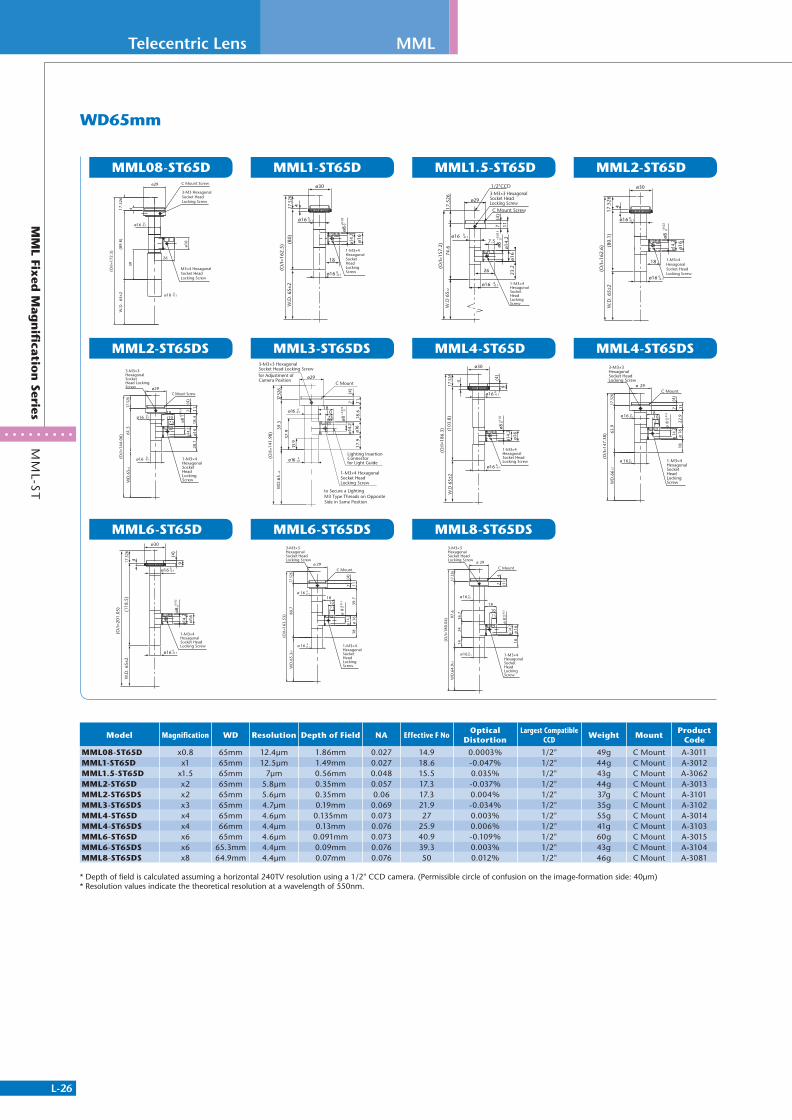
MML08-ST65D x0.8 65mm 12.4μm 1.86mm 0.027 14.9 0.0003% 1/2" 49g C Mount A-3011MML1-ST65D x1 65mm 12.5μm 1.49mm 0.027 18.6 -0.047% 1/2" 44g C Mount A-3012MML1.5-ST65D x1.5 65mm 7μm 0.56mm 0.048 15.5 0.035% 1/2" 43g C Mount A-3062MML2-ST65D x2 65mm 5.8μm 0.35mm 0.057 17.3 -0.037% 1/2" 44g C Mount A-3013MML2-ST65DS x2 65mm 5.6μm 0.35mm 0.06 17.3 0.004% 1/2" 37g C Mount A-3101MML3-ST65DS x3 65mm 4.7μm 0.19mm 0.069 21.9 -0.034% 1/2" 35g C Mount A-3102MML4-ST65D x4 65mm 4.6μm 0.135mm 0.073 27 0.003% 1/2" 55g C Mount A-3014MML4-ST65DS x4 66mm 4.4μm 0.13mm 0.076 25.9 0.006% 1/2" 41g C Mount A-3103MML6-ST65D x6 65mm 4.6μm 0.091mm 0.073 40.9 -0.109% 1/2" 60g C Mount A-3015MML6-ST65DS x6 65.3mm 4.4μm 0.09mm 0.076 39.3 0.003% 1/2" 43g C Mount A-3104MML8-ST65DS x8 64.9mm 4.4μm 0.07mm 0.076 50 0.012% 1/2" 46g C Mount A-3081
* Depth of field is calculated assuming a horizontal 240TV resolution using a 1/2" CCD camera. (Permissible circle of confusion on the image-formation side: 40μm)* Resolution values indicate the theoretical resolution at a wavelength of 550nm.
311766_MV_LensKatalog.indd 26 07.09.11 15:01
L-27
MM
L-ST
MM
L Fixed
Mag
nifi
cation
Series
MML08-ST65
MML2-ST65S
MML6-ST65
MML1-ST65
MML3-ST65S
MML6-ST65S
MML1.5-ST65
MML4-ST65
MML8-ST65S
MML2-ST65
MML4-ST65S
ø29 C Mount Screw
3-M3 Hexagonal Socket Head Locking Screw
17.5
26(8
9.8)
W.D
. 65
±2
(O/I
=172
.3)
4
ø18 0-0.1
ø16 0-0.1
3-M3×3 Hexagonal Socket Head Locking Screw
C Mount
(O/I
=144
.06)
WD
.65±
2
ø 16 0-0.1
61.5
40.1
16.1
17.5
26
16 0-0.1
(4)
7 11
29ø
ø
17.5
26
4
(118
.5)
(O/I
=201
.05)
(4)
9
ø16
ø30
0-0.1
ø16 0-0.1
W.D
. 65±
2
W.D
. 65±
2(8
0)17
.526
(O/I
=162
.5)
4
ø30
ø16 0-0.1
ø16 0-0.1
3-M3×3 Hexagonal Socket Head Locking Screw
C Mount
ø 16 0-0.1
WD
.65±
259
.517
.526
(O/I
=141
.98)
37.9
13.9
ø 16 0-0.1
(4)
7 11
ø 29
3-M3×3 Hexagonal Socket Head Locking Screw
C Mount
WD
.65.
3±2
ø 16 0-0.1
14
17.5
2680
.7
(O/I
=163
.53)
38
ø 16 0-0.1
(4)
7 11
ø 29
23 MOMML
3-M3×3 Hexagonal Socket Head Locking ScrewC Mount Screw
1/2"CCD
ø29
11(4
)7
17.5
2674
.6
(O/I
=157
.2)
W.D
65±
2
ø16 0-0.1
ø16 0-0.1
4
ø30
ø16 0-0.1
ø16 0-0.1
17.5
26(1
03.8
)W
.D 6
5±2
(O/I
=186
.3)
9(4
)
3-M3×3 Hexagonal Socket Head Locking Screw
C Mount
14
WD
.64.
9±2
ø 16 0-0.1
17.5
26
(O/I
=180
.04)
2416
.7
97.6
ø 29
(11)
74
ø16
ø30
0-0.1
ø16 0-0.1
17.5
26
4
(80.
1)W
.D. 6
5±2
(O/I
=162
.6)
3-M3×3 Hexagonal Socket Head Locking Screw
C Mount
ø 16 0-0.1
ø 16 0-0.1
WD
.66±
2
(O/I
=147
.38)
63.9
38
14
16.7
17.5
26
(4)
7 11
ø 29
Model Magnification WD Resolution Depth of Field NA Effective F NoOptical
DistortionLargest Compatible
CCDWeight Mount
Product Code
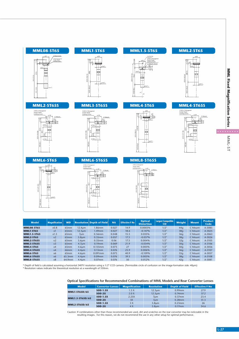
MML08-ST65 x0.8 65mm 12.4μm 1.86mm 0.027 14.9 0.0003% 1/2" 44g C Mount A-3085MML1-ST65 x1 65mm 12.5μm 1.49mm 0.027 18.6 -0.147% 1/2" 38g C Mount A-3025MML1.5-ST65 x1.5 65mm 7μm 0.56mm 0.048 15.5 0.035% 1/2" 36g C Mount A-3063MML2-ST65 x2 65mm 5.8μm 0.35mm 0.057 17.3 -0.037% 1/2" 38g C Mount A-3026MML2-ST65S x2 65mm 5.6μm 0.35mm 0.06 17.3 0.004% 1/2" 32g C Mount A-3105MML3-ST65S x3 65mm 4.7μm 0.19mm 0.069 21.9 -0.034% 1/2" 30g C Mount A-3106MML4-ST65 x4 65mm 4.6μm 0.135mm 0.073 27 0.003% 1/2" 50g C Mount A-3056MML4-ST65S x4 66mm 4.4μm 0.13mm 0.076 25.9 0.006% 1/2" 36g C Mount A-3107MML6-ST65 x6 65mm 4.6μm 0.091mm 0.073 40.9 -0.109% 1/2" 55g C Mount A-3057MML6-ST65S x6 65.3mm 4.4μm 0.09mm 0.076 39.3 0.003% 1/2" 38g C Mount A-3108MML8-ST65S x8 64.9mm 4.4μm 0.07mm 0.076 50 0.012% 1/2" 42g C Mount A-3081
* Depth of field is calculated assuming a horizontal 240TV resolution using a 1/2" CCD camera. (Permissible circle of confusion on the image-formation side: 40μm)* Resolution values indicate the theoretical resolution at a wavelength of 550nm.
Optical Specifications for Recommended Combinations of MML Models and Rear Converter Lenses
Model Converter Lenses Magnification Resolution Depth of Field Effective F No
MML1-ST65D/65SOD-1.5X 1.5 X 12.5μm 0.99mm 27.9SOD-2X 2.0 X 12.5μm 0.74mm 37.2
MML1.5-ST65D/65SOD-1.5X 2.25X 7μm 0.37mm 23.4SOD-2X 3X 7μm 0.28mm 31.3
MML2-ST65D/65SOD-1.5X 3 X 5.8μm 0.23mm 26SOD-2X 4 X 5.8μm 0.17mm 34.6
Caution: If combinations other than those recommended are used, dirt and scratches on the rear converter may be noticeable in the resulting images. For this reason, we do not recommend the use in any other setup for optimal performance.
311766_MV_LensKatalog.indd 27 07.09.11 15:01

L-28
Telecentric Lens MML
MM
L-ST
MM
L Fixed
Mag
nifi
cation
Series
MML08-ST110D
MML3-ST110DS
MML1-ST110D
MML4-ST110D
MML2-ST110D
MML6-ST110D
MML2-ST110DS
MML8-ST110D
WD110mm74
.46
55
ø16
ø25
W.D
. 110
±3.3
ø309
(4)
(O/I
=256
.98)
17.5
26
0-0.1
0-0.1
1-M3×4 Hexagonal Socket Head Locking Screw
43.510
7.5
26
ø16
ø8 ø14.
2
+0.0
150
17.5
26
ø16
11
ø8 ø14.
2
1026
7.5
(4)
W.D
. 108
.3±3
.3
(O/I
=219
.74)
93.9
ø29
1643
.3
to Secure a LightingM3 Type Threads on Opposite Side in Same Position
Lighting Insertion Connector for Light Guide
MML
FG MO
for Adjustment of Camera Position
C Mount Screw
0-0.1
+0.0
30
1-M3×4 Hexagonal Socket Head Locking Screw
3-M3×3 Hexagonal Socket Head Locking Screw
ø18
50.4
244
W.D
. 11
3±3.
4
(4)
109.
817
.526
(O/I
=240
.3)
ø30
9
ø16 0-0.1
0-0.1
11-M3×4 Hexagonal Socket Head Locking Screw
26
7.510
ø14.
254
.4ø1
634
.5
ø8+0
.03
0
FG MML
MO
3-M3×3 Hexagonal Socket Head Locking Screw
C Mount Screwø29
114
17.5
2681
.9
(O/I
=210
.29)
W.D
110
.8±3
.3
ø16 0-0.1
ø16 0-0.1
1-M3×4 Hexagonal Socket Head Locking Screw
ø14.
2
ø8+0
.02
0.00
ø16
29.226
7.5
ø8+0
.015
0
W.D
.110
±3.3
(4)
17.5
26
ø30
9
ø16 0-0.1
ø16 0-0.1
129.
4
(O/I
=256
.9)
1-M3×4 Hexagonal Socket Head Locking Screw
7.510
26
ø16
ø14.
264
.4
FG MML
MO
3-M3×3Hexagonal Socket Head Locking ScrewC Mount Screw
1/2"CCD
ø29
114
17.5
2610
5.7
(O/I
=233
.05)
W.D
109
.8±3
.3 ø16 0-0.1
ø16 0-0.1
1-M3×4 Hexagonal Socket Head Locking Screw
ø14.
2
ø8+0
.02
0.00
ø16
29.226
7.5
17.5
26
ø16
11
ø8 ø14.
2
10
26
7.5
(4)
W.D
. 112
±3.3
(O/I
=201
.33)
71.8
ø29
1621
.2
to Secure a LightingM3 Type Threads on Opposite Side in Same Position
Lighting Insertion Connector for Light Guide
MML
FG MO
for Adjustment of Camera Position
C Mount Screw
0-0.1
+0.0
3 0
3-M3×3 Hexagonal Socket Head Locking Screw
1-M3×4 Hexagonal Socket Head Locking Screw
FG MML
MO
3-M3×3Hexagonal Socket Head Locking ScrewC Mount Screw
1/2"CCD
ø29
114
17.5
2612
9.4
(O/I
=256
.3)
W.D
109
.3±3
.3 ø16 0-0.1
ø16 0-0.1
1-M3×4 Hexagonal Socket Head Locking Screw
ø14.
2
ø8+0
.02
0.00
ø16
29.226
7.5
FG MML
MO
Model Magnification WD Resolution Depth of Field NA Effective F NoOptical
DistortionLargest Compatible
CCDWeight Mount
Product Code
MML08-ST110D 0.8x 110.0mm 13.5μm 2.00mm 0.024 16.1 0.016% 1/2" 85g C Mount A-3002MML1-ST110D 1x 113.0mm 14μm 1.68mm 0.024 20.9 0.005% 1/2" 58g C Mount A-3003MML2-ST110D 2x 110.0mm 11μm 0.66mm 0.03 33.2 0.031% 1/2" 55g C Mount A-3004MML2-ST110DS 2x 112.0mm 11.2μm 0.66mm 0.03 33.2 0.008% 2/3" 39g C Mount A-3109MML3-ST110DS 3x 108.3mm 11.2μm 0.44mm 0.03 49.7 0.008% 2/3" 43g C Mount A-3110MML4-ST110D 4x 110.8mm 7μm 0.164mm 0.045 44.4 -0.006% 1/2" 43g C Mount A-3005MML6-ST110D 6x 109.8mm 7μm 0.164mm 0.045 66.4 -0.008% 1/2" 48g C Mount A-3006MML8-ST110D 8x 109.3mm 7μm 0.17mm 0.045 88.4 -0.007% 1/2" 54g C Mount A-3007
311766_MV_LensKatalog.indd 28 07.09.11 15:01
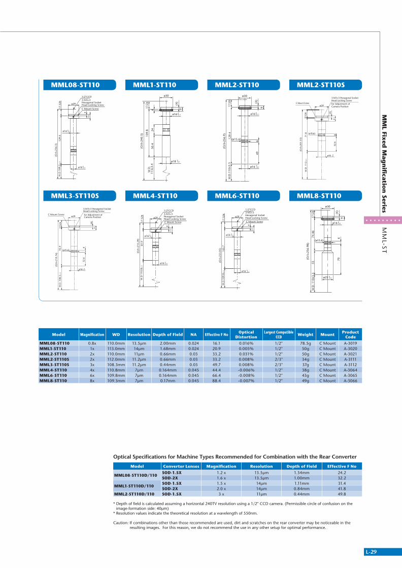
L-29
MM
L Fixed
Mag
nifi
cation
SeriesM
ML-S
T
MML08-ST110
MML3-ST110S
MML1-ST110
MML4-ST110
MML2-ST110
MML6-ST110
MML2-ST110S
MML8-ST110
ML8-ST110EX RoHS FG
3-M3×3Hexagonal Socket Head Locking Screw
C Mount Screw
1/2"CCD
ø29
114
17.5
2612
9.4
(O/I
=256
.3)
W.D
109
.3±3
.3
ø16 0-0.1
ø16 0-0.1
17.5
26
ø16
11(4
)
W.D
. 108
.3±3
.3
(O/I
=219
.74)
93.9
ø29
(ø15.6)
632
.6
3-M3×3 Hexagonal Socket Head Locking Screw
C Mount Screw
FGL3-ST110SORITEX RoHS
0-0.1
for Adjustment of Camera Position
ø18
50.4
244
W.D
. 11
3±3.
4
(4)
109.
817
.526
(O/I
=240
.3)
ø30
9
ø16 0-0.1
0-0.1
ML4-ST110EX RoHS FG
3-M3×3Hexagonal Socket Head Locking ScrewC Mount Screw
1/2"CCD
ø29
114
17.5
2681
.9
(O/I
=210
.29)
W.D
110
.8±3
.3
ø16 0-0.1
ø16 0-0.1
W.D
.110
±3.3
(4)
17.5
26
ø30
9
ø16 0-0.1
ø16 0-0.1
496
(ø15.6)129.
4
(O/I
=256
.9)
ML6-ST110EX RoHS FG
3-M3×3Hexagonal Socket Head Locking Screw
C Mount Screw
1/2"CCD
ø29
114
17.5
2610
5.7
(O/I
=233
.05)
W.D
109
.8±3
.3 ø16 0-0.1
ø16 0-0.1
17.5
26
ø16
11
(4)
W.D
. 112
±3.3
(O/I
=201
.33)
71.8
ø29
632
.6
(ø15.6)
3-M3×3 Hexagonal Socket Head Locking Screw
C Mount Screw
FGL2-ST110SORITEX RoHS
0-0.1
for Adjustment ofCamera Position
706
(ø15.6)
74.4
655
ø16
ø25
W.D
. 110
±3.3
ø30
9
(4)
(O/I
=256
.98)
17.5
26
0-0.1
0-0.1
Model Magnification WD Resolution Depth of Field NA Effective F NoOptical
DistortionLargest Compatible
CCDWeight Mount
Product Code
MML08-ST110 0.8x 110.0mm 13.5μm 2.00mm 0.024 16.1 0.016% 1/2" 78.5g C Mount A-3019MML1-ST110 1x 113.0mm 14μm 1.68mm 0.024 20.9 0.005% 1/2" 50g C Mount A-3020MML2-ST110 2x 110.0mm 11μm 0.66mm 0.03 33.2 0.031% 1/2" 50g C Mount A-3021MML2-ST110S 2x 112.0mm 11.2μm 0.66mm 0.03 33.2 0.008% 2/3" 34g C Mount A-3111MML3-ST110S 3x 108.3mm 11.2μm 0.44mm 0.03 49.7 0.008% 2/3" 37g C Mount A-3112MML4-ST110 4x 110.8mm 7μm 0.164mm 0.045 44.4 -0.006% 1/2" 38g C Mount A-3064MML6-ST110 6x 109.8mm 7μm 0.164mm 0.045 66.4 -0.008% 1/2" 43g C Mount A-3065MML8-ST110 8x 109.3mm 7μm 0.17mm 0.045 88.4 -0.007% 1/2" 49g C Mount A-3066
Optical Specifications for Machine Types Recommended for Combination with the Rear Converter
Model Converter Lenses Magnification Resolution Depth of Field Effective F No
MML08-ST110D/110SOD-1.5X 1.2 x 13.5μm 1.34mm 24.2SOD-2X 1.6 x 13.5μm 1.00mm 32.2
MML1-ST110D/110SOD-1.5X 1.5 x 14μm 1.11mm 31.4SOD-2X 2.0 x 14μm 0.84mm 41.8
MML2-ST110D/110 SOD-1.5X 3 x 11μm 0.44mm 49.8
* Depth of field is calculated assuming a horizontal 240TV resolution using a 1/2" CCD camera. (Permissible circle of confusion on the image-formation side: 40μm)
* Resolution values indicate the theoretical resolution at a wavelength of 550nm.
Caution: If combinations other than those recommended are used, dirt and scratches on the rear converter may be noticeable in the resulting images. For this reason, we do not recommend the use in any other setup for optimal performance.
311766_MV_LensKatalog.indd 29 07.09.11 15:01

L-30
Telecentric Lens MML
MM
L-ST
MM
L Fixed
Mag
nifi
cation
Series
WD150mm
MML08-ST170D MML1-ST150D MML08-ST170 MML1-ST150
(O/I
=314
.73)
124.
3W
.D 1
72.9
±5.2
17.5
26 (4)
9
ø22
ø25
4
ø30
0-0.1
0-0.1
1-M3×4 Hexagonal Socket Head Locking Screw
ø8 ø14.
2
ø16
7.5
25.7
74.3
+0.0
50
ø22
ø25
(4)
4
17.5
2613
7.8
(O/I
=311
.3)
W.D
. 156
±4.7
ø30
9
0-0.1
0-0.1
1-M3×4 Hexagonal Socket Head Locking Screw
ø16
ø14.
2
25.7
7.5
74.3
ø8+0
.05
0
(O/I
=314
.73)
124.
3W
.D 1
72.9
±5.2
17.5
26 (4)
9
ø22
ø25
4
ø30
0-0.1
0-0.1
ø22
ø25
(4)
4
17.5
2613
7.8
(O/I
=311
.3)
W.D
. 156
±4.7
ø30
9
0-0.1
0-0.1
Model Magnification WD Resolution Depth of Field NA Effective F NoOptical
DistortionLargest Compatible
CCDWeight Mount
Product Code
MML08-ST170D 0.8x 172.9 12μm 1.79mm 0.028 14 0.005% 1/2" 80g C Mount A-3008MML1-ST150D 1x 156.0 8.8μm 1.05mm 0.038 13 0.153% 1/2" 90g C Mount A-3009MML08-ST170 0.8x 172.9 12μm 1.79mm 0.028 14 0.005% 1/2" 76g C Mount A-3022MML1-ST150 1x 156.0 8.8μm 1.05mm 0.038 13 0.153% 1/2" 84g C Mount A-3023
* Resolution values indicate the theoretical resolution at a wavelength of 550nm.* Depth of field is calculated assuming a horizontal 240TV resolution using a 1/2" CCD camera. (Permissible circle of confusion on the image-formation side: 40μm)
Optical Specifications for Machine Types Recommended for Combination with Rear Converter
Model Converter Lenses Magnification Resolution Depth of Field Effective F No
MML08-ST170D/170SOD-1.5X 1.2x 12μm 1.17mm 21SOD-2X 1.6x 12μm 0.88mm 28
MML1-ST150D/150SOD-1.5X 1.5x 8.8μm 0.69mm 19.5SOD-2X 2.0x 8.8μm 0.52mm 26
Caution: If combinations other than those recommended are used, dirt and scratches on the rear converter may be noticeable in the resulting images. For this reason, we do not recommend the use in any other setup for optimal performance.
311766_MV_LensKatalog.indd 30 07.09.11 15:02
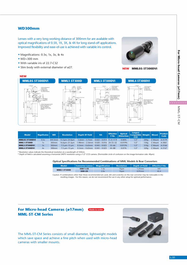
L-31
MML05-ST300DVI
MM
L-ST
-CM
For M
icro-h
ead C
ameras (ø
17m
m)
WD300mm
MML1-ST300D MML3-ST300DVI MML4-ST300DVI
• Magnifications: 0.5x, 1x, 3x, & 4x • WD=300 mm • With variable iris of 22.7-C32 • Slim body with external diameter of ø27.
Lenses with a very long working distance of 300mm for are available with optical magnifications of 0.5X, 1X, 3X, & 4X for long stand-off applications. Improved flexibility and ease-of-use is achieved with variable iris control.
The MML-ST-CM Series consists of small diameter, lightweight models which save space and achieve a fine pitch when used with micro-head cameras with smaller mounts.
Aperture Set Screw
M3 Lighting Set Screw (not bonded)
3-Camera Direction Adjustment Screw
12
ø30
28.4
10
5.8
25.8
103
ø16
ø14.
2ø8
116
W.D
. 305
±9
ø27ø30
10
4
(201
)
O/I
523
.5 (
IN A
IR)
17.5
26
ø27
+0.0
30
0-0.1
Optical Specifications for Recommended Combinations of MML Models & Rear Converters
Model Converter Lenses Magnification Resolution Depth of Field Effective F No
MML1-ST300DSOD-1.5X 1.5x 15μm 1.21mm 341SOD-2X 2.0x 15μm 0.91mm 45.4
Caution: If combinations other than those recommended are used, dirt and scratches on the rear converter may be noticeable in the resulting images. For this reason, we do not recommend the use in any other setup for optimal performance.
Model Magnification WD Resolution Depth Of Field NA Effective F No
Optical Distortion
Largest Compatible
CCDWeight Mount Product
Code
MML05-ST300DVI 0.5x 344.5mm 15.3μm~24.0μm 3.6mm ~ 5.7mm 0.022 ~ 0.014 11.4~17.9 0.06% 1/2" 200g C Mount A-3179MML1-ST300D 1x 305mm 16.6μm~21.5μm 1.98mm ~ 2.56mm 0.020 ~ 0.016 24.72~32 -0.019% 1/2" 150g C Mount A-3061MML3-ST300DVI 3x 302mm 7.5 μm~15 μm 0.3mm ~ 0.65mm 0.045 ~ 0.023 33~66 0.015% 1/2" 310g C Mount A-3166MML4-ST300DVI 4x 300mm 7.5 μm~15 μm 0.3mm ~ 0.65mm 0.045 ~ 0.023 44~88 0.01% 1/2" 320g C Mount A-3167
* Resolution values indicate the theoretical resolution at a wavelength of 550nm.* Depth of field is calculated assuming a horizontal 240TV resolution using a 1/2" CCD camera. (Permissible circle of confusion on the image-formation side: 40μm)
120.
95
87.4
17.5
26ø32
56.6
W.D
.30
2.18
210.
274
145.
95(O/I
=529
.98)
4
ø15.
7ø1
4.2 12.5
ø40 0-0.1
ø30 0-0.1
ø30 0-0.1
ø8+0
.05
0
3-M3 HexagonalSocket HeadLocking Screw for Adjustment of Camera Position
C Mount
M3x4 Hexagonal Socket Head Locking Screw to Secure a LightingM3 Type Threads on Opposite Side in Same Position
120.
9587
.4
17.5
26
ø32
82.7
W.D
.30
0.0
236.
424
145.
95
ø15.
7ø1
4.2 12.5
(O/I
=553
.95)
ø40 0-0.1
ø30 0-0.1
ø30 0-0.1
ø8+0
.05
0
3-M3 HexagonalSocket HeadLocking Screw for Adjustment of Camera Position
C Mount
M3x4 Hexagonal Socket Head Locking Screw to Secure a LightingM3 Type Threads on Opposite Side in Same Position
NEW MML05-ST300DVI
NEW
C Mount
3-M2.6 HexagonalSocket HeadLocking Screw for Adjustment of Camera Position
1-M3x4 Hexagonal Socket Head Locking Screw to Secure a LightingM3 Type Threads on Opposite Side in Same Position76
.2
17.5
26 4
1222
.310
9399.5
166.
1
(O/I
=531
.6)
W.D
. 348
±10 ø36 0
-0.1
ø30
ø30
ø16
ø14.
2
28.310
5.8
ø27 0-0.1
ø8+0
.05
0
For Micro-head Cameras (ø17mm)MML-ST-CM Series
Made-to-order
311766_MV_LensKatalog.indd 31 07.09.11 15:02
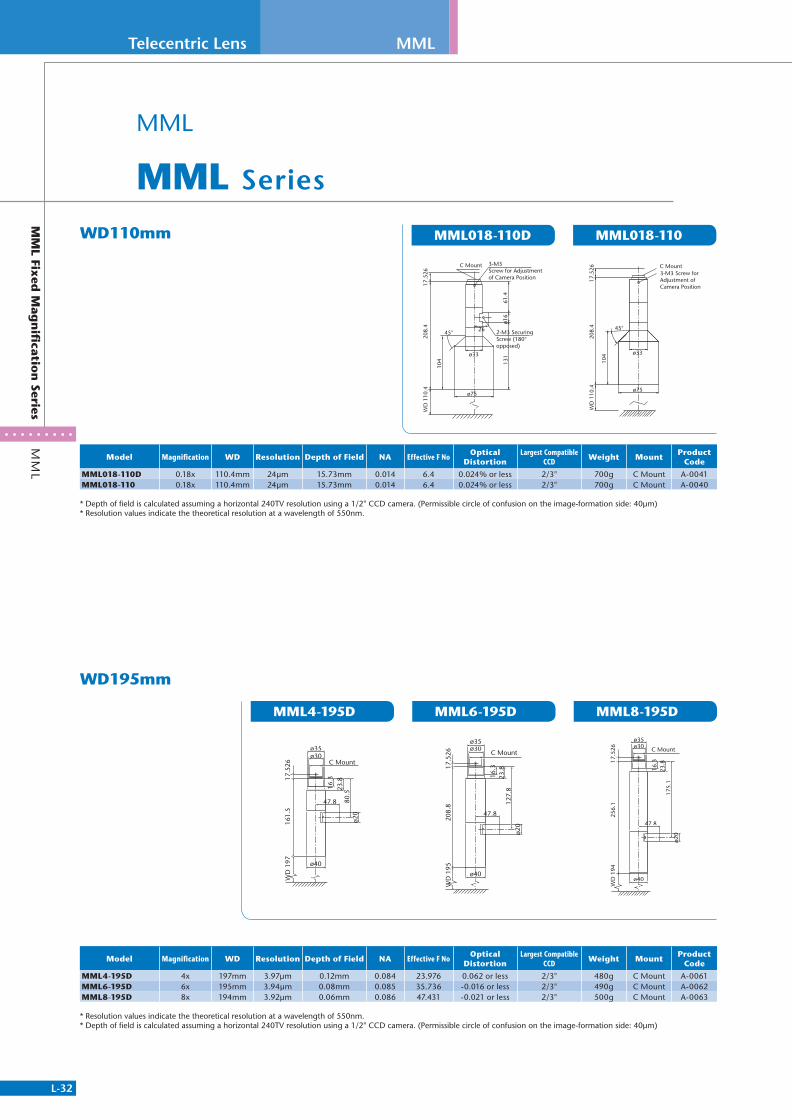
L-32
Telecentric Lens MML
MM
L Fixed
Mag
nifi
cation
SeriesM
ML
WD195mm
MML4-195D MML6-195D MML8-195D
WD110mm MML018-110D MML018-110
MML
MML Series
Model Magnification WD Resolution Depth of Field NA Effective F NoOptical
DistortionLargest Compatible
CCDWeight Mount
Product Code
MML4-195D 4x 197mm 3.97μm 0.12mm 0.084 23.976 0.062 or less 2/3" 480g C Mount A-0061MML6-195D 6x 195mm 3.94μm 0.08mm 0.085 35.736 -0.016 or less 2/3" 490g C Mount A-0062MML8-195D 8x 194mm 3.92μm 0.06mm 0.086 47.431 -0.021 or less 2/3" 500g C Mount A-0063
* Resolution values indicate the theoretical resolution at a wavelength of 550nm.* Depth of field is calculated assuming a horizontal 240TV resolution using a 1/2" CCD camera. (Permissible circle of confusion on the image-formation side: 40μm)
ø35
C Mountø30
ø40
23.8
80.5
16.3
161.
5W
D 1
9717
.526
47.8
ø20
ø35
C Mountø30
ø40
47.8
ø20
23.8
127.
8
16.3
208.
8W
D 1
9517
.526
ø35
C Mountø30
ø40
47.8
ø20
23.8
175.
1
16.3
256.
1W
D 1
9417
.526
Model Magnification WD Resolution Depth of Field NA Effective F NoOptical
DistortionLargest Compatible
CCDWeight Mount
Product Code
MML018-110D 0.18x 110.4mm 24μm 15.73mm 0.014 6.4 0.024% or less 2/3" 700g C Mount A-0041MML018-110 0.18x 110.4mm 24μm 15.73mm 0.014 6.4 0.024% or less 2/3" 700g C Mount A-0040
* Depth of field is calculated assuming a horizontal 240TV resolution using a 1/2" CCD camera. (Permissible circle of confusion on the image-formation side: 40μm)* Resolution values indicate the theoretical resolution at a wavelength of 550nm.
3-M3Screw for Adjustment of Camera Position
C Mount
17.5
2620
8.4
WD
110
.4
104 13
1ø1
661
.4
ø75
45°
ø33
26 2-M3 Securing Screw (180°opposed)
ø75
45°
104
208.
417
.526
WD
110
.4
3-M3 Screw for Adjustment of Camera Position
C Mount
ø33
311766_MV_LensKatalog.indd 32 07.09.11 15:02
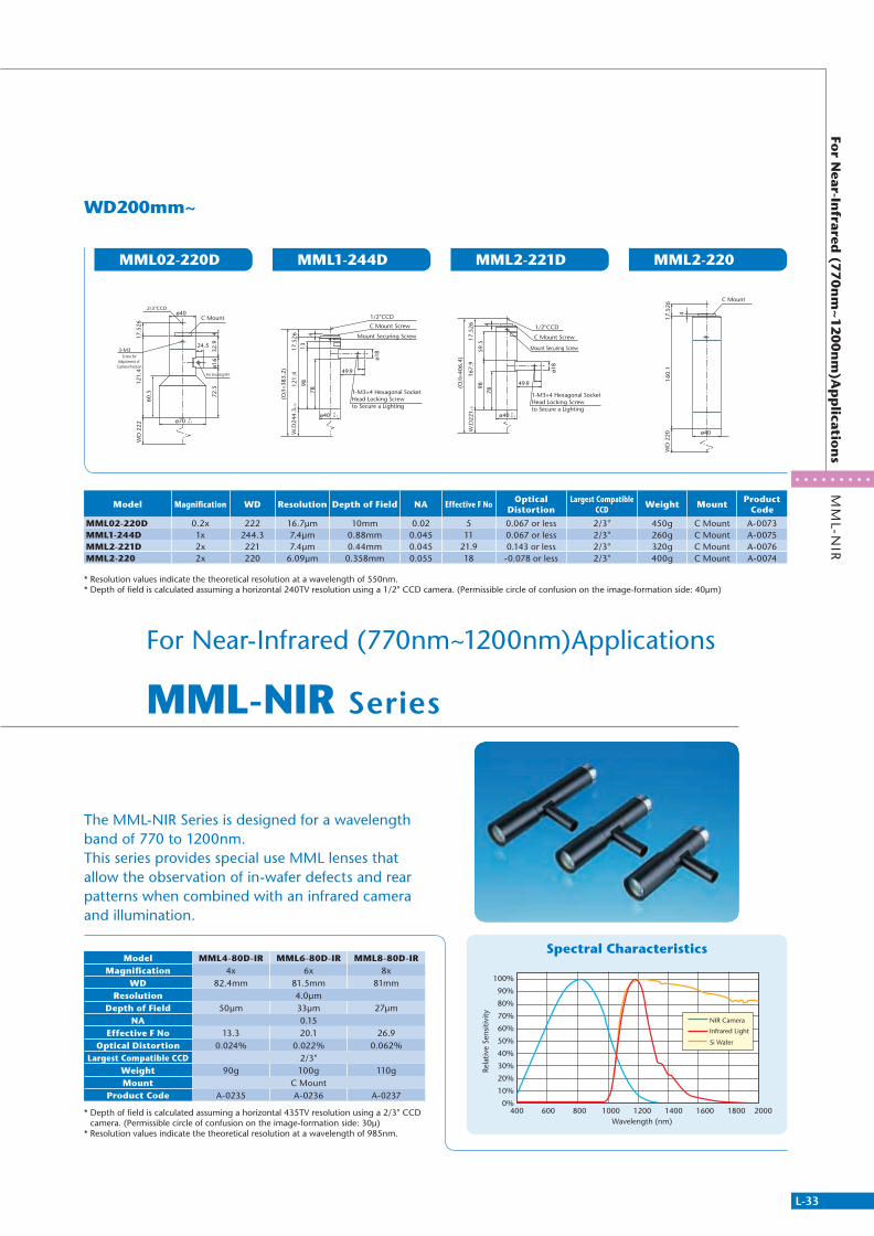
L-33
MM
L-NIR
For N
ear-Infrared
(770n
m~1200n
m)A
pp
lication
s
WD200mm~
MML02-220D MML1-244D MML2-221D MML2-220
For Near-Infrared (770nm~1200nm)Applications
MML-NIR Series
The MML-NIR Series is designed for a wavelength band of 770 to 1200nm.This series provides special use MML lenses that allow the observation of in-wafer defects and rear patterns when combined with an infrared camera and illumination.
Spectral Characteristics
Model Magnification WD Resolution Depth of Field NA Effective F NoOptical
DistortionLargest Compatible
CCDWeight Mount
Product Code
MML02-220D 0.2x 222 16.7μm 10mm 0.02 5 0.067 or less 2/3" 450g C Mount A-0073MML1-244D 1x 244.3 7.4μm 0.88mm 0.045 11 0.067 or less 2/3" 260g C Mount A-0075MML2-221D 2x 221 7.4μm 0.44mm 0.045 21.9 0.143 or less 2/3" 320g C Mount A-0076MML2-220 2x 220 6.09μm 0.358mm 0.055 18 -0.078 or less 2/3" 400g C Mount A-0074
* Resolution values indicate the theoretical resolution at a wavelength of 550nm.* Depth of field is calculated assuming a horizontal 240TV resolution using a 1/2" CCD camera. (Permissible circle of confusion on the image-formation side: 40μm)
72.5
ø16
32.9
4
ø70
121.
4
60.5
17.5
26W
D 2
22
ø40
24.5
0-0.1
3-M3
For Securing M3
2/3"CCD
Screw for Adjustment of
Camera Position
C Mount
Mount Securing Screw
1-M3×4 Hexagonal Socket Head Locking Screwto Secure a Lighting
C Mount Screw
1/2"CCD
ø40
ø18
49.9
17.5
2612
1.4
9878
413
W.D
244.
3±12
(O/I
=383
.2)
0-0.1
Mount Securing Screw
1-M3×4 Hexagonal Socket Head Locking Screwto Secure a Lighting
C Mount Screw
1/2"CCD
ø40
ø18
49.9
17.5
2616
7.9
9878
459
.5
W.D
221±
11
(O/I
=406
.4)
0-0.1
ø40
WD
220
160.
117
.526
4
C Mount
100%
90%
80%
70%
60%
50%
40%
30%
20%
10%
0%400 600 800 1000 1200 1400 1600 1800 2000
Wavelength (nm)
Si Wafer
Infrared Light
NIR Camera
Rela
tive
Sens
itivi
ty
Model MML4-80D-IR MML6-80D-IR MML8-80D-IRMagnification 4x 6x 8x
WD 82.4mm 81.5mm 81mmResolution 4.0μm
Depth of Field 50μm 33μm 27μmNA 0.15
Effective F No 13.3 20.1 26.9Optical Distortion 0.024% 0.022% 0.062%
Largest Compatible CCD 2/3"Weight 90g 100g 110gMount C Mount
Product Code A-0235 A-0236 A-0237
* Depth of field is calculated assuming a horizontal 435TV resolution using a 2/3" CCD camera. (Permissible circle of confusion on the image-formation side: 30μ)
* Resolution values indicate the theoretical resolution at a wavelength of 985nm.
311766_MV_LensKatalog.indd 33 07.09.11 15:02
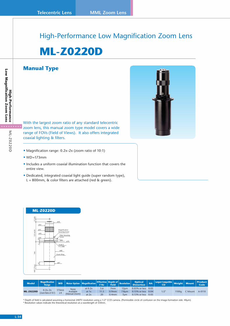
L-34
Telecentric Lens
ML-Z
02
20
DH
igh
-Perfo
rman
ce Lo
w M
agn
ificatio
n Z
oo
m Len
s
MML Zoom Lens
High-Performance Low Magnification Zoom Lens
ML-Z0220D
• Magnification range: 0.2x~2x (zoom ratio of 10:1)
• WD=173mm
• Includes a uniform coaxial illumination function that covers the entire view.
• Dedicated, integrated coaxial light guide (super random type), L = 800mm, & color filters are attached (red & green).
With the largest zoom ratio of any standard telecentric zoom lens, this manual zoom type model covers a wide range of FOVs (Field of Views). It also offers integrated coaxial lighting & filters.
ML-Z0220D
ModelMagnification
RangeWD Motor Option Magnification
Effective F No
Depth of Field
ResolutionOptical
DistortionNA
Largest CompatibleCCD
Weight MountProduct
Code
ML-Z0220D0.2x~2x
(Zoom Ratio of 10:1)173mm
±4
None Available
(Manual Zoom)
at 0.2x 3.6 7mm 12μm 0.03% or less 0.031/2" 1100g C Mount A-0110at 1x 11.5 0.9mm 7.8μm 0.15% or less 0.04
at 2x 20 0.4mm 7μm 0.13% or less 0.05
* Depth of field is calculated assuming a horizontal 240TV resolution using a 1/2" CCD camera. (Permissible circle of confusion on the image-formation side: 40μm)* Resolution values indicate the theoretical resolution at a wavelength of 550nm.
Manual Type
Magnification Securing Screw
Fiber Securing Screw
Zoom Ring
4×ø4.5P.C.D80
WD
173
±412
1.4±
10
55
22
ø68
ø90
ø59
ø55
ø52
ø50
ø50
ø70
ø61
144
17.5
26
311766_MV_LensKatalog.indd 34 07.09.11 15:02
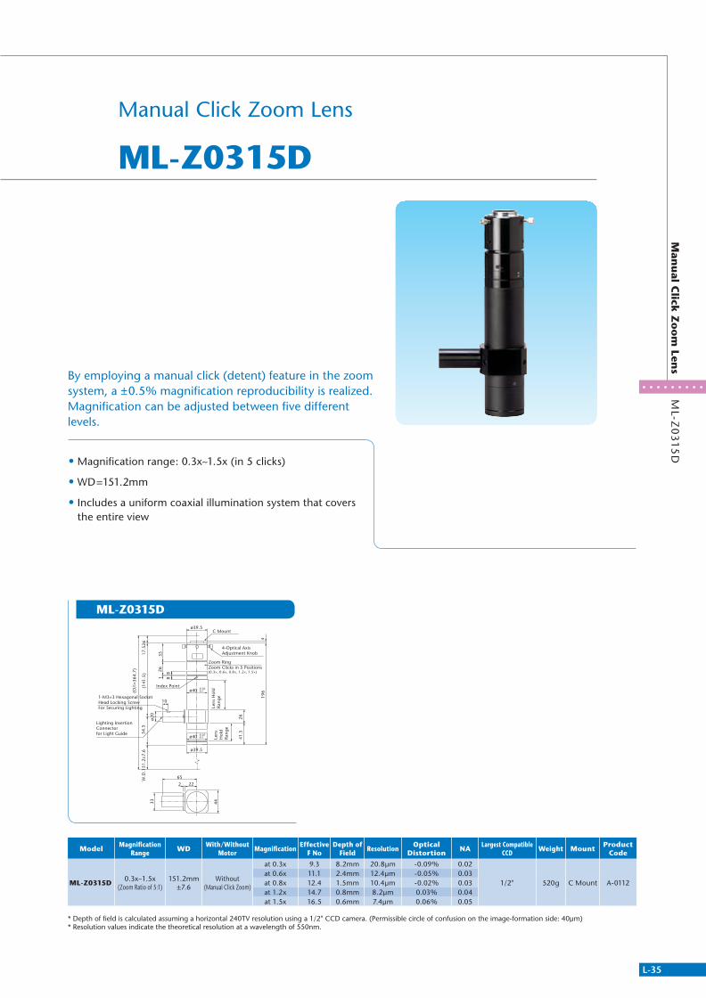
L-35
ML-Z
03
15
DM
anu
al Click
Zo
om
Lens
Manual Click Zoom Lens
ML-Z0315D
• Magnification range: 0.3x~1.5x (in 5 clicks)
• WD=151.2mm
• Includes a uniform coaxial illumination system that covers the entire view
By employing a manual click (detent) feature in the zoom system, a ±0.5% magnification reproducibility is realized. Magnification can be adjusted between five different levels.
ML-Z0315D
ModelMagnification
RangeWD
With/Without Motor
MagnificationEffective
F NoDepth of
FieldResolution
Optical Distortion
NALargest Compatible
CCDWeight Mount
Product Code
ML-Z0315D0.3x~1.5x
(Zoom Ratio of 5:1)151.2mm
±7.6Without
(Manual Click Zoom)
at 0.3x 9.3 8.2mm 20.8μm -0.09% 0.02
1/2" 520g C Mount A-0112at 0.6x 11.1 2.4mm 12.4μm -0.05% 0.03at 0.8x 12.4 1.5mm 10.4μm -0.02% 0.03at 1.2x 14.7 0.8mm 8.2μm 0.03% 0.04at 1.5x 16.5 0.6mm 7.4μm 0.06% 0.05
* Depth of field is calculated assuming a horizontal 240TV resolution using a 1/2" CCD camera. (Permissible circle of confusion on the image-formation side: 40μm)* Resolution values indicate the theoretical resolution at a wavelength of 550nm.
C Mountø39.5
ø39.5
65
33 �44
222
ø40
ø20
10
3526
196
26
4
41.5
1
88
17.5
26(1
41.5
)
(O/I
=364
.7)
54.5
W.D
.151
.2±7
.6
Index Point
1-M3×3 Hexagonal Socket Head Locking ScrewFor Securing Lighting
4-Optical Axis Adjustment Knob
Zoom RingZoom Clicks in 5 Positions(0.3×, 0.6×, 0.8×, 1.2×, 1.5×)
Lighting Insertion Connector for Light Guide
Len
s H
old
Ra
ng
e
Len
s H
old
Ra
ng
e
-0.02-0.1
ø40 -0.02-0.1
311766_MV_LensKatalog.indd 35 07.09.11 15:02

L-36
Telecentric Lens
Hig
h R
esolu
tion
Zo
om
Lens
ML-Z
07
54
5H
R
MML Zoom Lens
High Resolution Zoom Lens
ML-Z07545HR Series
• Zoom Ratio 6:1 0.75x – 4.5x
• Effective F No 8.4 – Variable Aperture
• Focus Range +/- 3mm
• NA 0.12 (4.5x)
• Working Distance = 70.9 mm
ML-Z07545HR ML-Z07545HRD-LML-Z07545HRD
To exploit the full potential of high pixel count cameras, this unique high NA, high resolution telecentric zoom lens series has a long working distance and wide zoom ratio as well as adjustable iris & focus. Available with an integrated coaxial illumination system as well as other options, this lens series is versatile and ideal for extremely accurate gauging and inspection applications at various field of views (FOVs).
518
18
9741
.7
ø40
W.D
. 70.
9±2.
1
ø48
2822
13
ø43
48(ø54)
ø35ø30
ø36
4
(O/I
=303
.9)
17.5
26(2
15.5
) 4-M3 Depth 5
Zoom ring
Focus Ring ±3
C Mount (1-32UNF)
ApertureAdjustment Ring
13.8
Adj
ustm
ent
±4.5
62.3
18
185
48
ø16
19
40
ø14.
2ø8
(ø54)
4-M3 Depth 5
Zoom ring
ApertureAdjustment Ring
Lighting Insertion Connector for Light Guide
4-M3 Depth 5
Zoom ring
ApertureAdjustment Ring
Focus Ring ±3
C Mount (1-32UNF)
41.7
97
49
ø40
19
W.D
. 70.
9±2.
1
ø48
5
18
18
ø14.
2
2822
13
ø43
48(ø54)
ø16
ø35ø30
ø36
4
(O/I
=303
.9)
17.5
26(2
15.5
)
ø8
13.8
Adj
ustm
ent
±4.5
Lighting Insertion Connector for Light Guide
Model Magnification Range WD Focus
Position Magnification Effective F No
Depth of Field Resolution Optical
Distortion NA WeightLargest
Compatible CCD
Mount Product Code
ML-Z07545HR0.75x ~ 4.5x 70.9mm
±2.1±3mm
at 0.75x 8.4 1.2mm 7.5μm -0.02% 0.04Approx. 650g 1/2'' C Mount
A-3143ML-Z07545HRD at 2x 12 0.2mm 4.0μm 0.01% 0.08 A-3144ML-Z07545HRD-L - at 4.5x 19 0.07mm 2.8μm 0.02% 0.12 A-3145
* Effective F No indicates designed value when iris is open* Calculated based on permissible circle of confusion on the image-formation side:40μm
ML-Z07545HR Coaxial Illumination Model D 90°, Side View Model-L
Lineup : 3 Models
311766_MV_LensKatalog.indd 36 07.09.11 15:02
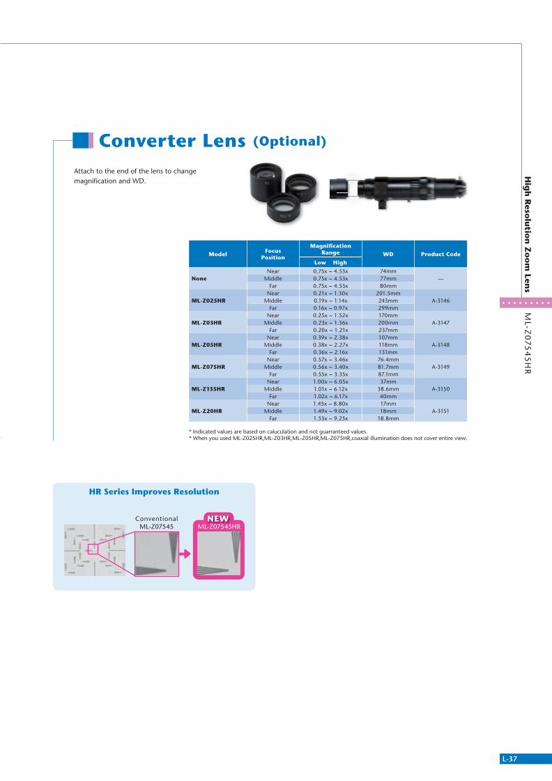
L-37
ML-Z
07
54
5H
RH
igh
Reso
lutio
n Z
oo
m Len
s
Converter Lens (Optional)
Attach to the end of the lens to change magnifi cation and WD.
HR Series Improves Resolution
ML-Z07545Conventional NEW
ML-Z07545HR
ModelFocus
Position
Magnifi cation Range WD Product Code
Low High
NoneNear 0.75x ~ 4.53x 74mm
—Middle 0.75x ~ 4.53x 77mmFar 0.75x ~ 4.53x 80mm
ML-Z025HRNear 0.21x ~ 1.30x 201.5mm
A-3146Middle 0.19x ~ 1.14x 243mmFar 0.16x ~ 0.97x 299mm
ML-Z03HRNear 0.25x ~ 1.52x 170mm
A-3147Middle 0.23x ~ 1.36x 200mmFar 0.20x ~ 1.21x 237mm
ML-Z05HRNear 0.39x ~ 2.38x 107mm
A-3148Middle 0.38x ~ 2.27x 118mmFar 0.36x ~ 2.16x 131mm
ML-Z075HRNear 0.57x ~ 3.46x 76.4mm
A-3149Middle 0.56x ~ 3.40x 81.7mmFar 0.55x ~ 3.35x 87.1mm
ML-Z135HRNear 1.00x ~ 6.05x 37mm
A-3150Middle 1.01x ~ 6.12x 38.6mmFar 1.02x ~ 6.17x 40mm
ML-Z20HRNear 1.45x ~ 8.80x 17mm
A-3151Middle 1.49x ~ 9.02x 18mmFar 1.53x ~ 9.25x 18.8mm
* Indicated values are based on caluculation and not guarranteed values.* When you used ML-Z025HR,ML-Z03HR,ML-Z05HR,ML-Z075HR,coaxial illumination does not cover entire view.
311766_MV_LensKatalog.indd 37 07.09.11 15:02
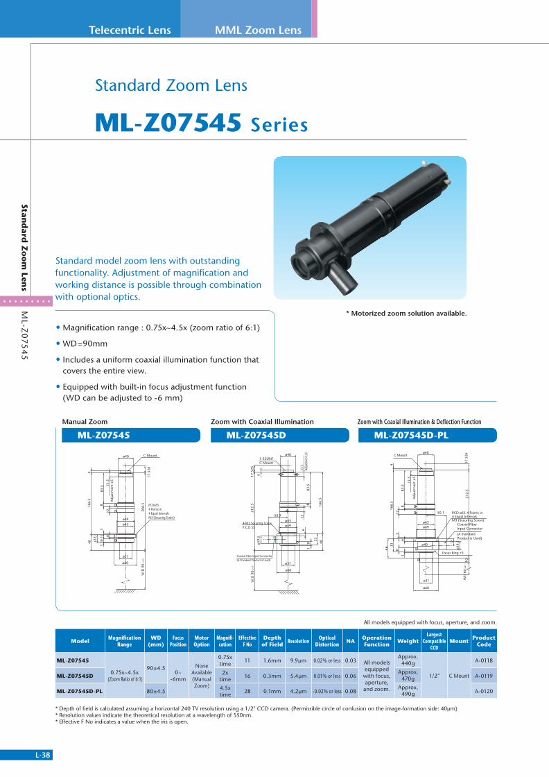
L-38
Telecentric Lens
ML-Z
07
54
5Stan
dard
Zo
om
Lens
MML Zoom Lens
• Magnification range : 0.75x~4.5x (zoom ratio of 6:1)
• WD=90mm
• Includes a uniform coaxial illumination function that covers the entire view.
• Equipped with built-in focus adjustment function (WD can be adjusted to -6 mm)
Standard Zoom Lens
ML-Z07545 Series
Standard model zoom lens with outstanding functionality. Adjustment of magnification and working distance is possible through combination with optional optics.
ML-Z07545 ML-Z07545D ML-Z07545D-PL
* Motorized zoom solution available.
ModelMagnification
RangeWD
(mm)Focus
PositionMotor Option
Magnifi-cation
Effective F No
Depth of Field
ResolutionOptical
DistortionNA
Operation Function
WeightLargest
Compatible CCD
MountProduct
Code
ML-Z07545
0.75x~4.5x (Zoom Ratio of 6:1)
90±4.50~
-6mm
None Available (Manual Zoom)
0.75x time
11 1.6mm 9.9μm 0.02% or less 0.03 All models equipped
with focus, aperture,
and zoom.
Approx. 440g
1/2" C Mount
A-0118
ML-Z07545D2x
time16 0.3mm 5.4μm 0.01% or less 0.06
Approx. 470g A-0119
ML-Z07545D-PL 80±4.54.5x time
28 0.1mm 4.2μm -0.02% or less 0.08Approx.
490g A-0120
* Depth of field is calculated assuming a horizontal 240 TV resolution using a 1/2" CCD camera. (Permissible circle of confusion on the image-formation side: 40μm)* Resolution values indicate the theoretical resolution at a wavelength of 550nm.* Effective F No indicates a value when the iris is open.
PCDø55 4 Points in 4 Equal Intervals M3 (Securing Screw)
ø40
ø31
ø43ø49
ø60
17.5
26
206.
5
166.
5
(22)
440
311 6
101
12
883
.5 13.5
Adj
ustm
ent
±5
W.D
90
±4.5
C Mount
11
4-M3 Securing ScrewP.C.D 55
1-32UNFC Mount
ø40
ø43ø49
50.9
17.5
2621
2.5 16
6.5
33
4
46
6
1
12
883
.5
13.5
Adju
stmen
t ±5
ø19.
5
Coaxial Fiber Input Connector
(A Standard Product is Used)ø31
ø60
W.D
90
±4.5
PCD ø55 4 Points in 4 Equal IntervalsM3 (Securing Screw)
Focus Ring ±3
Coaxial Fiber Input Connector
(A Standard Product is Used)
46
36
3316
6.5
4
ø60
C Mountø40
ø49
ø31
50.1
ø43
ø40
ø19.
517
11
1
12
883
.5
13.5
Adj
ustm
ent
±5
WD
80
1021
2.5
17.5
26±4
.5
Manual Zoom Zoom with Coaxial Illumination
All models equipped with focus, aperture, and zoom.
Zoom with Coaxial Illumination & Deflection Function
311766_MV_LensKatalog.indd 38 07.09.11 15:02

L-39
Op
tion
sStan
dard
Zo
om
Lens
Standard Zoom Lens
Options
ML-Z2X
ML-Z Series
MML-P5
ML-Z2X
Front Converter Lens
Prism Adapter
Rear Converter Lens
Attach to end of lens to change magnification and working distance.
90° side view pentaprism type adapter.Monitor images are shown in an upright, normal position by the pentaprism.
Specially designed 2x rear converter. Mounting this between a lens and CCD camera can double the magnification easily without changing working distance.*May decrease the resolution.
*Magnification and working distance can be altered slightly by turning the focus adjustment ring (N F) Indicated values are based on calculation formulas. Actual measurement may differ depending on tolerance. Cannot be mounted on ML-Z07545D-PL.
16.45 4 0.7
ø30
(knu
rl)
C M
ount
ø16
ø29.
4
C M
ount
ML-Z
2X
Model Product Code
MML-P5 A-8009
Model Product Code
ML-Z2X A-8036
Model Product Code
ML-Z03 A-8025
ML-Z04 A-8026
ML-Z05 A-8027
ML-Z07 A-8028
ML-Z14 A-8029
ML-Z20 A-8030
ModelFocus
Position
ML-Z07545 ML-Z07545DMagnification
Range WDMatching
Chart
Magnification Range WD
Matching Chart
MIN MAX MIN MAX
ML-Z03Near 0.24x ~ 1.43x 255mm 0.23x ~ 1.4x 263mm
Coaxial Illumination Cannot Cover the Entire View
Middle 0.23x ~ 1.36x 283mm 0.22x ~ 1.33x 292mmFar 0.21x ~ 1.28x 315mm 0.21x ~ 1.25x 325mm
ML-Z04Near 0.31x ~ 1.87x 195mm 0.31x ~ 1.84x 200mm
Coaxial Illumination Cannot Cover the Entire View
Middle 0.3x ~ 1.81x 211mm 0.3x ~ 1.81x 216mmFar 0.29x ~ 1.72x 229mm 0.29x ~ 1.72x 234mm
ML-Z05Near 0.38x ~ 2.27x 160mm 0.37x ~ 2.25x 163mm
Coaxial Illumination Cannot Cover the Entire View
Middle 0.37x ~ 2.24x 170mm 0.37x ~ 2.21x 174mmFar 0.36x ~ 2.2x 181mm 0.36x ~ 2.17x 185mm
ML-Z07Near 0.52x ~ 3.17x 114mm 0.52x ~ 3.16x 115mm
Coaxial Illumination Cannot Cover the Entire View
Middle 0.53x ~ 3.16x 119mm 0.52x ~ 3.16x 121mmFar 0.53x ~ 3.17x 125mm 0.52x ~ 3.16x 126mm
ML-Z14Near 1.03x ~ 6.21x 53.4mm 1.03x ~ 6.21x 53.8mm
Middle 1.05x ~ 6.33x 54.7mm 1.06x ~ 6.37x 55.1mmFar 1.08x ~ 6.49x 56.1mm 1.08x ~ 6.49x 56.5mm
ML-Z20Near 1.45x ~ 8.77x 32.1mm 1.46x ~ 8.77x 32.3mm
Middle 1.49x ~ 9.01x 32.7mm 1.5x ~ 9.09x 32.9mmFar 1.54x ~ 9.26x 33.4mm 1.54x ~ 9.35x 33.6mm
MML CCD Camera
311766_MV_LensKatalog.indd 39 07.09.11 15:02

L-40
Telecentric Lens
MM
L-PL
25
HR
/ MM
L-PL
90° Sid
e View
Mirro
r Type P
rism
Accessory
MML-PL25HR
MML-PL16 MML-PL18 MML-PL25
MML CCD Camera
Inner Optical Path Length
WD Below Prism = Lens WD - Inner Optical Path Length
28
ø25+0.1 0
285
1035
ø19
22.5
4-M3 (For Securing Lens)M3 Hexagonal Socket Set Screw (4 Screws Enclosed)
Center of Field of View ± (Lens WD × tan1.5° or less)
Inner Optical Path Length 26.5
ø25 MML-HR Series
Center of Field of View ± (Lens WD x tan1.5° or less)
4-M2.6 (For Securing Lens)M2.6 Hexagonal Socket Set Screw(4 Screws Enclosed)
Inner Optical Path Length 20
25
3515
6
ø13
20
20
ø16 +0.10
Center of Field of View ± (Lens WD ×tan1.5° or less)
4-M2.6 (For Securing Lens)M2.6 Hexagonal Socket Set Screw (4 Screws Enclosed)
Inner Optical Path Length 20
156
25
3520
20
ø13
ø18 +0.10
Inner Optical Path Length 26
4-M3 (For Securing Lens)M2.6 Hexagonal Socket Set Screw(4 Screws Enclosed)
Center of Field of View ± (Lens WD × tan1.5° or less)
22.5
27
27
1035
5
ø19
ø25 +0.10
When used in optical systems, images may blur or bend due to the strong effects of profi le irregularity of prisms. A clear image can be acquired, however, even for HR type lenses with large NA by sorting and removing prisms with high profi le irregularity during the QC process.
Using these prisms, the optical axis can be bent at a 90° right angle which is useful when space is limited. Resulting images become mirror images.
• Exclusive MML-High Resolution
• Lens barrel diameter ø25
• Length of inner optical path length 26.5mm
90˚ Side View Mirror Type Prism for MML-HR
90˚ Side View Mirror Type Prism
MML-PL25HR
MML-PL Series
Prism adapters make it possible to bend the optical axis at a right angle of 90°,
and to perform mark recognition for microscopic objects by modifying the
pitch between 2 MML lenses to a fi ne pitch.
Prism Adapters
Model MML-PL25HR
Specifi cations 90° Side View Mirrorfor HR For ø25
Product Code A-8013
Model Compatible Sizes Inner Optical Path Length
Product Code
MML-PL16 For ø16 Lens 20mm A-8004MML-PL18 For ø18 Lens 20mm A-8005MML-PL25 For ø25 Lens 26mm A-8006MML-GA20 Cover Glass ø20 t=1mm A-8062
Cover Glass MML-GA20
311766_MV_LensKatalog.indd 40 07.09.11 15:02
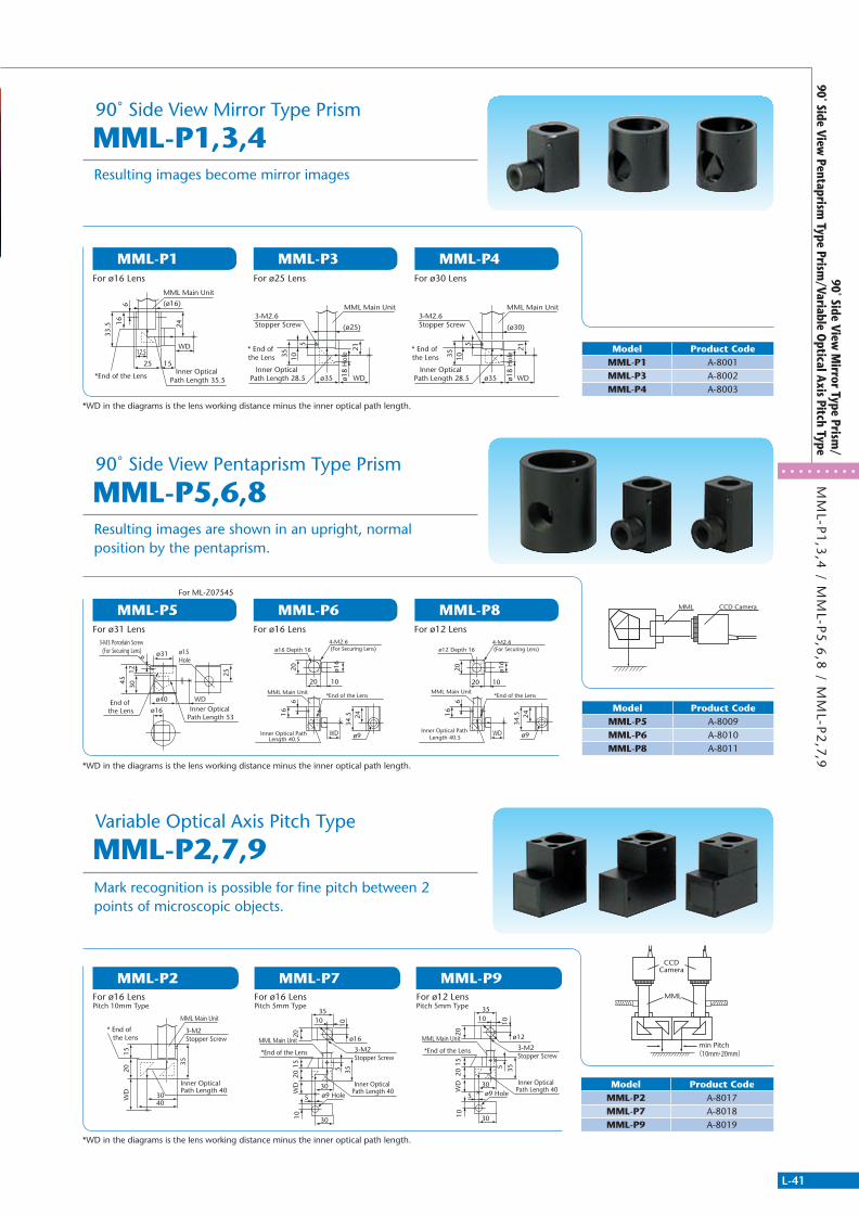
L-41
MM
L-P1
,3,4
/ MM
L-P5
,6,8
/ MM
L-P2
,7,990˚ Side View
Mirror Type Prism
/90˚ Side View
Pentaprism Type Prism
/Variable Optical Axis Pitch Type
MML-P2
MML-P5
MML-P1
MML-P7
MML-P6
MML-P3
MML-P9
MML-P8
MML-P4
Resulting images are shown in an upright, normal position by the pentaprism.
Resulting images become mirror images
90˚ Side View Pentaprism Type Prism
90˚ Side View Mirror Type Prism
MML-P5,6,8
MML-P1,3,4
MML
CCDCamera
min Pitch(10mm・20mm)
MML CCD Camera
12.5
25
WD
15
33.5 16
6
24
*End of the LensInner Optical
Path Length 35.5
MML Main Unit
(ø16)
3040
1520
35
WD
* End of the Lens
Inner Optical Path Length 40
MML Main Unit
3-M2Stopper Screw
ø35 WD
35 10
ø18
Hol
e
5
21
(ø25)
* End of the Lens
Inner Optical Path Length 28.5
MML Main Unit3-M2.6Stopper Screw
ø35 WD
35 10
ø18
Hol
e
5
21
(ø30)
* End of the Lens
Inner Optical Path Length 28.5
MML Main Unit3-M2.6Stopper Screw
ø40 WD
ø31 ø15 Hole
45
612
30
25
End of the Lens Inner Optical
Path Length 53ø16
3-M3 Porcelain Screw (For Securing Lens)
16
ø16
ø16 Depth 16
20 10
20
WD
*End of the Lens
Inner Optical Path Length 40.5
6
4-M2.6 (For Securing Lens)
MML Main Unit
2434
.5
ø9
ø16
30
5
3510
30
1520
355
10W
D
*End of the Lens
Inner Optical Path Length 40
MML Main Unit3-M2Stopper Screw
20
10
ø9 Hole
16
ø16
ø12 Depth 16
20 10
20
WD
*End of the Lens
Inner Optical Path Length 40.5
6
4-M2.6 (For Securing Lens)
MML Main Unit
2434
.5
ø9
ø12
30
5
3510
30
1520
355
10W
D
*End of the Lens
Inner Optical Path Length 40
MML Main Unit3-M2Stopper Screw
20
10
ø9 Hole
Mark recognition is possible for fi ne pitch between 2 points of microscopic objects.
Variable Optical Axis Pitch Type
MML-P2,7,9
Model Product CodeMML-P1 A-8001MML-P3 A-8002MML-P4 A-8003
Model Product CodeMML-P5 A-8009MML-P6 A-8010MML-P8 A-8011
Model Product CodeMML-P2 A-8017MML-P7 A-8018MML-P9 A-8019
*WD in the diagrams is the lens working distance minus the inner optical path length.
*WD in the diagrams is the lens working distance minus the inner optical path length.
*WD in the diagrams is the lens working distance minus the inner optical path length.
For ø16 LensPitch 10mm Type
For ø31 Lens
For ø16 Lens
For ML-Z07545
For ø16 Lens
For ø25 Lens
For ø12 Lens
For ø30 Lens
For ø16 LensPitch 5mm Type
For ø12 LensPitch 5mm Type
311766_MV_LensKatalog.indd 41 07.09.11 15:02
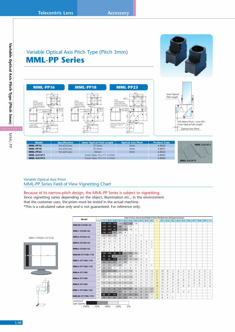
L-42
Telecentric Lens
MM
L-PP
Variab
le Op
tical Axis P
itch Typ
e (Pitch
3m
m)
Accessory
ModelField of View (Horizontal Field of View Divided into 20 Equal Sections)
CCD -1 -0.9 -0.8 -0.7 -0.6 -0.5 -0.4 -0.3 -0.2 -0.1 0 0.1 0.2 0.3 0.4 0.5 0.6 0.7 0.8 0.9 1
MML08-ST65D/651/2" -100 -100 -100 -100 -82 -50 -18 1/3" -100 -99 -82 -58 -33 -11
MML1-ST65D/651/2" -100 -100 -92 -70 -43 -18 -1 1/3" -100 -100 -43 -24 -8
MML2-ST65D/651/2" -34 -28 -22 -17 -12 -7 -3 -1 1/3" -19 -15 -12 -8 -5 -3 -1
MML4-ST65D/651/2" -15 -13 -11 -9 -7 -6 -4 -3 -2 -1 1/3" -10 -9 -7 -6 -5 -4 -3 -2 -1 -1
MML6-ST65D/651/2" -9 -7 -6 -5 -4 -3 -3 -2 -1 -1 1/3" -6 -5 -4 -4 -3 -2 -2 -1 -1
MML08-ST110D/1101/2" -100 -100 -96 -83 -67 -50 -33 -17 -4 1/3" -90 -80 -67 -54 -41 -28 -17 -7
MML1-ST110D/1101/2" -93 -83 -72 -60 -47 -34 -22 -12 -3 1/3" -66 -56 -47 -37 -28 -19 -12 -5 -1
MML2-ST110D/1101/2" -37 -32 -27 -22 -17 -13 -9 -6 -3 -1 1/3" -24 -21 -17 -14 -11 -8 -6 -3 -1
MML4-ST110D1/2" -25 -24 -22 -21 -19 -18 -16 -15 -14 -12 -11 -10 -8 -7 -6 -5 -4 -3 -2 -2 -1 1/3" -21 -20 -19 -18 -17 -16 -15 -14 -13 -12 -11 -10 -9 -8 -7 -7 -6 -5 -4 -4 -3
MML6-ST110D1/2" -20 -19 -18 -17 -16 -15 -14 -13 -12 -11 -11 -10 -9 -8 -7 -7 -6 -5 -4 -4 -3 1/3" -17 -17 -16 -15 -15 -14 -13 -13 -12 -11 -11 -10 -9 -9 -8 -8 -7 -6 -6 -5 -5
MML8-ST110D1/2" -17 -16 -16 -15 -14 -14 -13 -12 -12 -11 -10 -10 -9 -9 -8 -7 -7 -6 -6 -5 -5 1/3" -15 -15 -14 -14 -13 -13 -12 -12 -11 -11 -10 -10 -9 -9 -9 -8 -8 -7 -7 -6 -6
MML1-ST150D/1501/2" -70 -65 -60 -54 -49 -43 -38 -32 -27 -22 -17 -13 -9 -5 -2 1/3" -57 -53 -49 -44 -40 -36 -32 -28 -25 -21 -17 -14 -11 -8 -5 -3 -1
MML08-ST170D/1701/2" -88 -81 -74 -66 -58 -50 -42 -34 -26 -19 -12 -6 -2 1/3" -70 -64 -58 -52 -46 -40 -34 -28 -22 -17 -12 -8 -4 -1
MML-PP16 MML-PP18 MML-PP25
Variable Optical Axis Pitch Type (Pitch 3mm)
MML-PP Series
Inner Optical Path Length
Optical Axis Pitch
WD Below Prism = Lens WD - Inner Optical Path Length
4-M3M3 Hexagonal Socket Set Screw(4 Screws Enclosed)
Inner Optical Path Length 45
Center of Field of View ±(Lens WD x tan2.5° or less)
184.
512
36.527
203
24.5
10
5
2735
ø25 +0.10
4-M2.6M2.6 Hexagonal Socket Set Screw (4 Screws Enclosed)
133.
5
10
30
20
20
Inner Optical Path Length 37.5
17
20.5 35
.510
6
3
ø18 +0.10
Inner Optical Path Length 37.5
4-M2.6M2.6 Hexagonal Socket Set Screw (4 Screws Enclosed)
Center of Field of View ± (Lens WD x tan2.5° or less)
133.
5
17
10
20.5
35.5
106
3
30
20
20
ø16 +0.10
MML1-ST65D+1/2"CCD
-1 -0.8 -0.6 0 0.5 1-1 -0.8 -0.6 0 0.5 1
MML1-ST65D+1/2"CCD
-1 -0.8 -0.6 0 0.5 1-1 -0.8 -0.6 0 0.5 1
Lowering of Light Quantity
-100% -70% -40% -20% 0%
Model Specifi cation Inner Optical Path Length Optical Axis Pitch Product CodeMML-PP16 For ø16 Lens 37.5mm 3mm A-8020MML-PP18 For ø18 Lens 37.5mm 3mm A-8021MML-PP25 For ø25 Lens 45mm 3mm A-8022MML-GA1411 Cover Glass 14 x 11 t=1mm A-8063MML-GA1913 Cover Glass 19 x 13 t=1mm A-8064
MML-PP Series Field of View Vignetting Chart
Because of its narrow-pitch design, the MML-PP Series is subject to vignetting.Since vignetting varies depending on the object, illumination etc., in the environment that the customer uses, the prism must be tested in the actual machine.*This is a calculated value only and is not guaranteed. For reference only.
Variable Optical Axis Prism
MML-GA1913
MML-GA1411
311766_MV_LensKatalog.indd 42 07.09.11 15:02
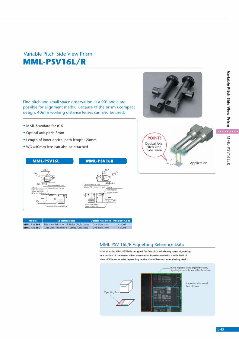
L-43
MM
L-PS
V1
6L
/RV
ariable P
itch Sid
e View
Prism
• MML-Standard for ø16
• Optical axis pitch 3mm
• Length of inner optical path length: 20mm
• WD=40mm lens can also be attached
Fine pitch and small space observation at a 90° angle are possible for alignment marks. Because of the prism's compact design, 40mm working distance lenses can also be used.
MML-PSV 16L/R Vignetting Reference DataNote that the MML-PSV16 is designed for fine pitch which may cause vignetting
in a portion of the screen when observation is performed with a wide field of
view. (Differences exist depending on the kind of lens or camera being used.)
MML-PSV16L MML-PSV16R
Vignetting Area
During inspection with a large field of vision, vignetting occurs in the area within the red box.
Inspection with a small field of vision
Application
POINT!Optical Axis Pitch One Side 3mm
± (Lens WD × tan2.5° or less)M2.6 Hexagonal Socket Set Screw (2 Screws Enclosed)
23.79
9 18
ø16 +0.1 0
(3) (11.7)Center of Field of View
3 725
10
(7.5
)
2-M2.6
Inner Optical Path Length 20 (in air)
2-M2.6
Center of Field of View
Inner Optical Path Length 20 (in air)
M2.6 Hexagonal Socket Set Screw (2 Screws Enclosed)
± (Lens WD × tan2.5° or less)
23.79
(11.7) (3)
189
ø16
10
257 3
(7.5
)
+00
Model Specifications Optical Axis Pitch Product Code
MML-PSV16R Side View Prism for ST Series (Right Side) One Side 3mm A-8007MML-PSV16L Side View Prism for ST Series (Left Side) One Side 3mm A-8008
Variable Pitch Side View Prism
MML-PSV16L/R
311766_MV_LensKatalog.indd 43 07.09.11 15:02
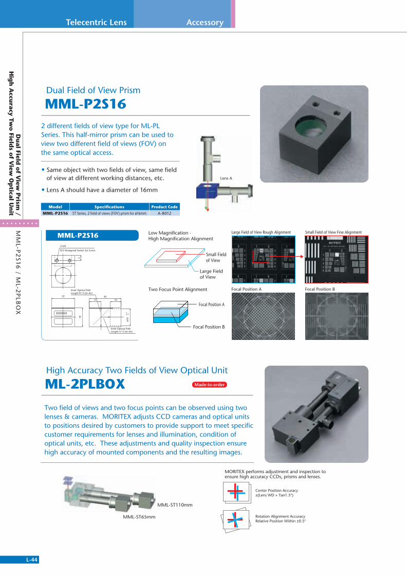
L-44
Telecentric Lens
MM
L-P2
S1
6 / M
L-2P
LBO
XD
ual Field
of V
iew P
rism /
Hig
h A
ccuracy Tw
o Field
s of V
iew O
ptical U
nit
Accessory
Two field of views and two focus points can be observed using two lenses & cameras. MORITEX adjusts CCD cameras and optical units to positions desired by customers to provide support to meet specific customer requirements for lenses and illumination, condition of optical units, etc. These adjustments and quality inspection ensure high accuracy of mounted components and the resulting images.
2 different fields of view type for ML-PL Series. This half-mirror prism can be used to view two different field of views (FOV) on the same optical access.
• Same object with two fields of view, same field of view at different working distances, etc.
• Lens A should have a diameter of 16mm
Lens A
Model Specifications Product Code
MML-P2S16 ST Series, 2 field of views (FOV) prism for ø16mm A-8012
MML-P2S162-M3
M3 Hexagonal Socket Set Screw
22
Inner Optical Path Length B 13 (In Air)
18
1130
10
ø16
Inner Optical Path Length A 13 (In Air)
5
+0.1
0
Large Field of View Rough Alignment Small Field of View Fine Alignment
Focal Position A Focal Position B
Low Magnification ·High Magnification Alignment
Two Focus Point Alignment
Small Field of View
Large Field of View
Focal Position A
Focal Position B
MML-ST110mm
MML-ST65mm
Center Position Accuracy±(Lens WD × Tan1.5°)
Rotation Alignment AccuracyRelative Position Within ±0.5°
MORITEX performs adjustment and inspection toensure high accuracy CCDs, prisms and lenses.
Made-to-order
Dual Field of View Prism
High Accuracy Two Fields of View Optical Unit
MML-P2S16
ML-2PLBOX
311766_MV_LensKatalog.indd 44 07.09.11 15:02
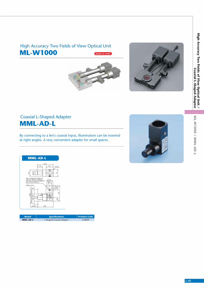
L-45
Hig
h A
ccuracy Tw
o Field
s of V
iew O
ptical U
nit /
Co
axial L-Sh
aped
Ad
apter
ML-W
10
00
/ MM
L-AD
-L
By connecting to a len's coaxial input, illumination can be inserted at right angles. A very convenient adapter for small spaces.
Model Specifi cations Product Code
MML-AD-L L-Shaped Coaxial Adapter A-8049
MML-AD-L
M3-4 Hexagonal Socket Set Screw to Secure a LightingM3 Type Threads on Opposite Side in Same Position
(MML Lens)
(ø5)
2×C2
ø14.2
ø14
12
35.5
16
(34)(ø16)
834
107.5
16
ø8-0
.01
-0.0
5
ø8 +0.050
(Fib
er B
undl
e D
iam
eter
)
Made-to-order
High Accuracy Two Fields of View Optical Unit
Coaxial L-Shaped Adapter
ML-W1000
MML-AD-L
311766_MV_LensKatalog.indd 45 07.09.11 15:02

L-46
Telecentric Lens
Total O
ptical Illu
min
ation
System
Custom Examples
Total Optical Illumination System
Infrared & Visible Ray Transmission System
Top and Bottom Dual Field Optical System (2CCD Type)
Twin-View, Dual Magnification/Twin-View, Dual Focal Optical System
Various OEM applications are available with combinations of more than 100 standard products and lights. Please contact us with inquiries.
A complete lens and lighting system which uses infrared rays to transmit through a Si, GaAs, or Ge substrate to recognize IR penetration patterns.
A space-saving optical system for attaching 2 opposite-facing objects with accuracy.
A space-saving optical system that is used to simultaneously observe an object at two focus distances, and two magnifications on one optical path utilizing a specific prism structure.
IR Camera
Infrared Lens
Visible Light Camera
Visible Light Lens
Si Interposer
CCD
CCDMML
MML
Low Magnification Side / Upper CCD High Magnification Side / Lower CCD
311766_MV_LensKatalog.indd 46 07.09.11 15:02
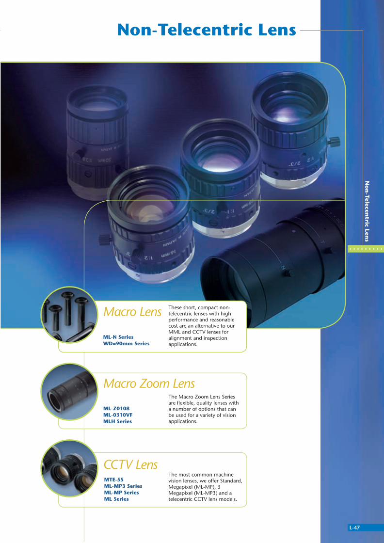
Non-Telecentric Lens
L-47
No
n-Telecen
tric Lens
The most common machine vision lenses, we offer Standard, Megapixel (ML-MP), 3 Megapixel (ML-MP3) and a telecentric CCTV lens models.
CCTV Lens
These short, compact non-telecentric lenses with high performance and reasonable cost are an alternative to our MML and CCTV lenses for alignment and inspection applications.
Macro Lens
The Macro Zoom Lens Series are fl exible, quality lenses with a number of options that can be used for a variety of vision applications.
Macro Zoom Lens
ML-N SeriesWD=90mm Series
ML-Z0108ML-0310VFMLH Series
MTE-55ML-MP3 SeriesML-MP SeriesML Series
311766_MV_LensKatalog.indd 47 07.09.11 15:02
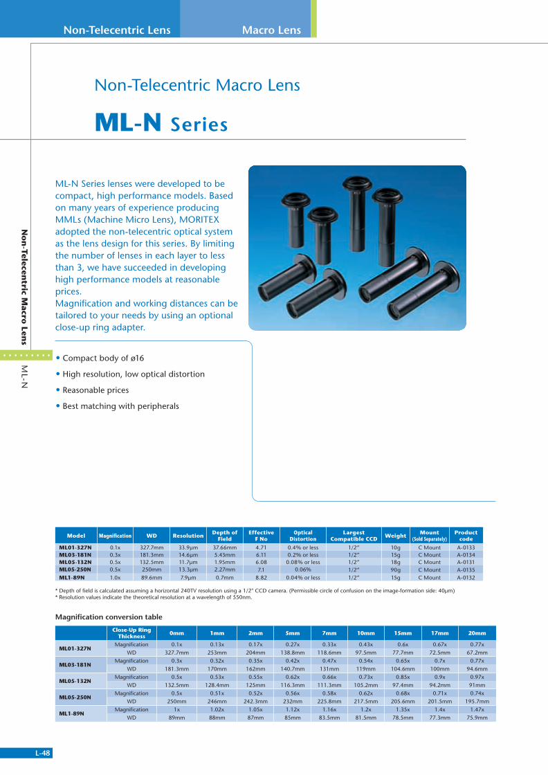
L-48
Non-Telecentric Lens
ML-N
No
n-Telecen
tric Macro
Lens
Macro Lens
Non-Telecentric Macro Lens
ML-N Series
• Compact body of ø16
• High resolution, low optical distortion
• Reasonable prices
• Best matching with peripherals
ML-N Series lenses were developed to be compact, high performance models. Based on many years of experience producing MMLs (Machine Micro Lens), MORITEX adopted the non-telecentric optical system as the lens design for this series. By limiting the number of lenses in each layer to less than 3, we have succeeded in developing high performance models at reasonable prices.Magnification and working distances can be tailored to your needs by using an optional close-up ring adapter.
Model Magnification WD Resolution Depth of Field
Effective F No
Optical Distortion
Largest Compatible CCD Weight Mount
(Sold Separately)Product
code
ML01-327N 0.1x 327.7mm 33.9μm 37.66mm 4.71 0.4% or less 1/2” 10g C Mount A-0133ML03-181N 0.3x 181.3mm 14.6μm 5.43mm 6.11 0.2% or less 1/2” 15g C Mount A-0134ML05-132N 0.5x 132.5mm 11.7μm 1.95mm 6.08 0.08% or less 1/2” 18g C Mount A-0131ML05-250N 0.5x 250mm 13.3μm 2.27mm 7.1 0.06% 1/2” 90g C Mount A-0135ML1-89N 1.0x 89.6mm 7.9μm 0.7mm 8.82 0.04% or less 1/2” 15g C Mount A-0132
* Depth of field is calculated assuming a horizontal 240TV resolution using a 1/2" CCD camera. (Permissible circle of confusion on the image-formation side: 40μm)* Resolution values indicate the theoretical resolution at a wavelength of 550nm.
Magnification conversion table
Close-Up Ring Thickness 0mm 1mm 2mm 5mm 7mm 10mm 15mm 17mm 20mm
ML01-327NMagnification 0.1x 0.13x 0.17x 0.27x 0.33x 0.43x 0.6x 0.67x 0.77x
WD 327.7mm 253mm 204mm 138.8mm 118.6mm 97.5mm 77.7mm 72.5mm 67.2mm
ML03-181NMagnification 0.3x 0.32x 0.35x 0.42x 0.47x 0.54x 0.65x 0.7x 0.77x
WD 181.3mm 170mm 162mm 140.7mm 131mm 119mm 104.6mm 100mm 94.6mm
ML05-132NMagnification 0.5x 0.53x 0.55x 0.62x 0.66x 0.73x 0.85x 0.9x 0.97x
WD 132.5mm 128.4mm 125mm 116.3mm 111.3mm 105.2mm 97.4mm 94.2mm 91mm
ML05-250NMagnification 0.5x 0.51x 0.52x 0.56x 0.58x 0.62x 0.68x 0.71x 0.74x
WD 250mm 246mm 242.3mm 232mm 225.8mm 217.5mm 205.6mm 201.5mm 195.7mm
ML1-89NMagnification 1x 1.02x 1.05x 1.12x 1.16x 1.2x 1.35x 1.4x 1.47x
WD 89mm 88mm 87mm 85mm 83.5mm 81.5mm 78.5mm 77.3mm 75.9mm
311766_MV_LensKatalog.indd 48 07.09.11 15:02
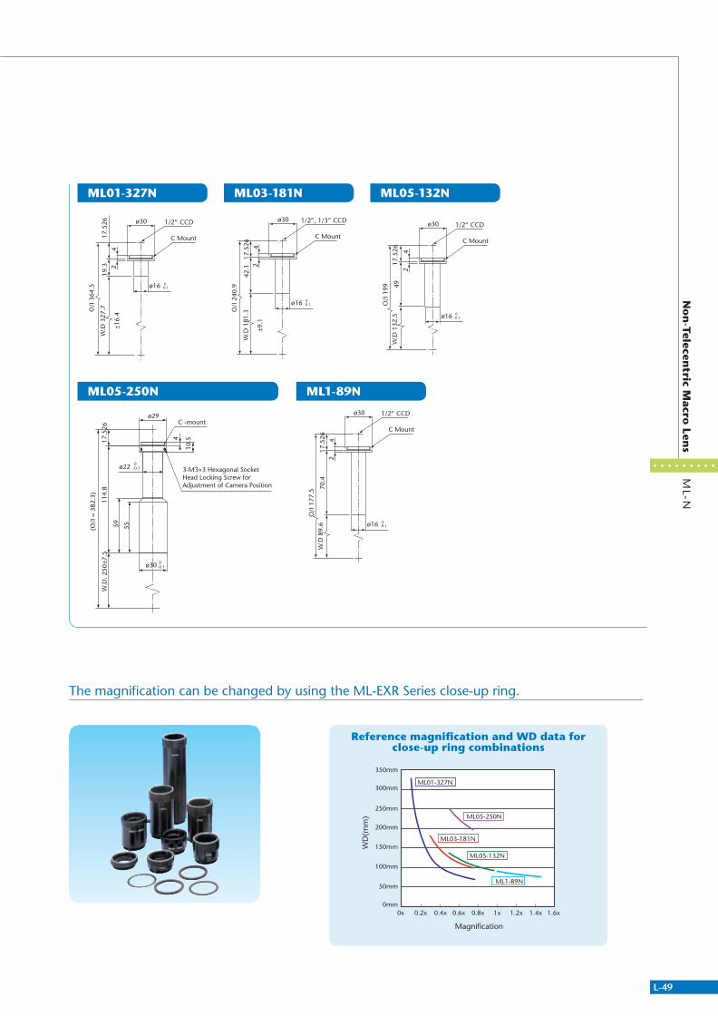
L-49
ML05-250N
ML-N
No
n-Telecen
tric Macro
Lens
ML01-327N ML03-181N ML05-132N
ML1-89N
The magnification can be changed by using the ML-EXR Series close-up ring.
Reference magnification and WD data for close-up ring combinations
ø30
ø16
C Mount
0-0.1
1/2” CCD
W.D
327
.7
±16.
4
O/I
364
.5
24
17.5
2619
.3
ø30
ø16
C Mount
0-0.1
1/2”, 1/3” CCD
W.D
181
.3
±9.1
O/I
240
.9
24
17.5
2642
.1
ø30
ø16
C Mount
0-0.1
1/2” CCD
W.D
132
.5
O/I
199
24
17.5
2649
ø30
ø16
C Mount
0-0.1
1/2” CCD
W.D
89.
6O
/I 1
77.5
24
17.5
2670
.4
Magnification
WD
(mm
)
ML01-327N
ML03-181N
ML05-250N
ML05-132N
ML1-89N
0mm
50mm
100mm
150mm
200mm
250mm
300mm
350mm
0x 0.2x 0.4x 0.6x 0.8x 1x 1.2x 1.4x 1.6x
17.5
26W
.D. 2
50±7
.5
(O/I
= 3
82.3
)
114.
8
ø29
ø30 0-0.1
59 55
ø22 0-0.1
10.54
C -mount
3-M3×3 Hexagonal Socket Head Locking Screw for Adjustment of Camera Position
311766_MV_LensKatalog.indd 49 07.09.11 15:02

L-50
Non-Telecentric Lens
WD
=9
0m
mLo
w M
agn
ifi cation
Macro
Lens
Macro Lens
ML-15014 ML-24030 ML-3505 ML-5010
Low Magnifi cation Macro Lens
WD=90mm Series
Small, high-resolution macro lenses to be mounted directly on machines. WD=90mm for all models.
17.5
2631
.8W
D 9
0
4
5(5
.6)
ø14
ø32
ø29
ø28
C Mount
17.5
2629
.8W
D 9
0
4
5
ø32
ø29
ø28
C Mount
17.5
2650
.5W
D 9
0
4
5
ø32
ø29
ø28
C Mount
M22.5 P0.5(Depth 3)ø24
17.5
2692
.6W
D 9
0
4
5
ø32
M22.5 P0.5(Depth 3)
ø29
ø28
ø24
Model Magnifi cation Effective F No WD Depth of Field ResolutionOptical
DistortionWeight
Largest Compatible CCD
MountProduct
Code
ML-15014 0.14x 4.6 90mm 18mm 36μm 0.1% or less 28g 2/3" C Mount A-0127ML-24030 0.3x 7.3 90mm 6.5mm 21μm 0.1% or less 39g 2/3" C Mount A-0128ML-3505 0.5x 8.4 90mm 2.7mm 13μm 0.1% or less 55g 2/3" C Mount A-0129ML-5010 1x 8 90mm 0.6mm 6.3μm 0.1% or less 68g 2/3" C Mount A-0130
* Depth of fi eld is calculated assuming a horizontal 240TV resolution using a 1/2" CCD camera. (Permissible circle of confusion on the image-formation side: 40μm)* Resolution values indicate the theoretical resolution at a wavelength of 550nm.
311766_MV_LensKatalog.indd 50 07.09.11 15:02

L-51
ML-Z
01
08
Hig
h P
erform
ance M
acro Z
oo
m Len
s
High Performance Macro Zoom Lens
ML-Z0108
• Zoom ratio of 8:1. Magnification range of 0.1x~0.8x
• WD=213mm
• Focus adjustment ±20mm (magnification variation ±13%)
• Iris, focus, and zoom are adjustable.
• Equipped with locking screws.
High performance macro lens with 8:1 magnification ratio and long working distance. By using the focus ring on the end, working distance can be changed within a range of 20mm.
ML-Z0108
Model Magnification WD Focus Position MotorEffective
F NoDepth of
FieldResolution
Optical Distortion
Operation Function
WeightLargest
Compatible CCDMount
Product Code
ML-Z01080.1x to 0.8x
(Zoom Ratio of 8:1)213mm
Without (Manual Zoom)
at 0.1x8.2
32.8mm 55μm -0.02% or less Manual (Adjusting Aperture, Zoom,
and Focus)140g 1/2" C Mount A-0155at 0.4x 2.1mm 14μm 0.18% or less
at 0.8x 9.3 0.6mm 8μm 0.17% or less
* Depth of field is calculated assuming a horizontal 240TV resolution using a 1/2" CCD camera. (Permissible circle of confusion on the image-formation side: 40μm)* Resolution values indicate the theoretical resolution at a wavelength of 550nm.
C Mount
ø32
ø28.5
ø30
ø28
WD
213
±6.4
108.
2
59.5 41
.5
34.7
27.3
17.5
26
Aperture Adjustment Ring
Zoom Ring
WD Adjustment Ring(Adjustment: ±1mm)
The Lens Cannot be Held
Filter Mounting ScrewM22.5 P0.5 (Note 1)
Range that the Lens Is Held
ø30 0-0.1
311766_MV_LensKatalog.indd 51 07.09.11 15:02
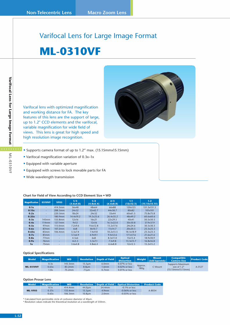
L-52
Non-Telecentric Lens Macro Zoom Lens
Varifo
cal Lens fo
r Large Im
age Fo
rmat
ML-0
31
0V
F
Varifocal Lens for Large Image Format
ML-0310VF
• Supports camera format of up to 1.2” max. (15.15mmx15.15mm)
• Varifocal magnification variation of 0.3x~1x
• Equipped with variable aperture
• Equipped with screws to lock movable parts for FA
• Wide wavelength transmission
Varifocal lens with optimized magnification and working distance for FA. The key features of this lens are the support of large, up to 1.2" CCD elements and the varifocal, variable magnification for wide field of views. This lens is great for high speed and high resolution image recognition.
Optical Specifications
Model Magnification WD Resolution Depth of FieldOptical
DistortionWeight
Mount (Sold Separately)
Compatible Camera Size
Product Code
ML-0310VF0.3x 143.5mm 15.3μm 6.0mm 0.07% or less
Approx. 180g
C MountSupports Maximum
size of 1.2" (15.15mmx15.15mm)
A-31270.65x 83.2mm 8.8μm 1.6mm 0.02% or less1.0x 75.2mm 7.1μm 0.7mm 0.01% or less
Option Proxar Lens
Model Magnification WD Resolution Depth of Field Optical Distortion Product Code
ML-VF030.1x 414.4mm 44.0μm 54.4mm -0.1% or less
A-80340.37x 133.4mm 15.3μm 4.9mm -0.06% or less0.65x 106.3mm 10.8μm 2.0mm -0.03% or less
* Calculated from permissible circle of confusion diameter of 40μm.* Resolution values indicate the theoretical resolution at a wavelength of 550nm.
Chart for Field of View According to CCD Element Size • WD
Magnification 0310VF VF031/3
(3.6x4.8)1/2
(4.8x6.4)2/3
(6.6x8.8)1.1
(12x12.3)1.2
(15.15x15.15)
0.1x - 414.5mm 36x48 48x64 66x88 120x123 151.5x151.50.15x - 288.5mm 24x32 32x42.7 44x58.7 80x82 101x1010.2x - 220.3mm 18x24 24x32 33x44 60x61.5 75.8x75.80.25x - 180.9mm 14.4x19.2 19.2x25.6 26.4x35.2 48x49.2 60.6x60.60.3x 143mm 155.8mm 12x16 16x21 22x29.3 40x41 50.5x50.5 0.4x 114mm 127.1mm 9x12 12x16 16.5x22.0 30x30.8 37.9x37.9 0.5x 97mm 113.0mm 7.2x9.6 9.6x12.8 13.2x17.6 24x24.6 30.3x30.3 0.6x 87mm 107.2mm 6x8 8x10.7 11x14.7 20x20.5 25.3x25.3
0.65x 83mm 106.4mm 5.5x7.4 7.4x9.8 10.2x13.5 18.5x18.9 23.3x23.3 0.7x 81mm - 5.1x6.9 6.9x9.1 9.4x12.6 17.1x17.6 21.6x21.6 0.8x 77mm - 4.5x6 6x8 8.3x11.0 15x15.4 18.9x18.9 0.9x 76mm - 4x5.3 5.3x7.1 7.3x9.8 13.3x13.7 16.8x16.8 1x 75mm - 3.6x4.8 4.8x6.4 6.6x8.8 12x12.3 15.2x15.2
311766_MV_LensKatalog.indd 52 07.09.11 15:02
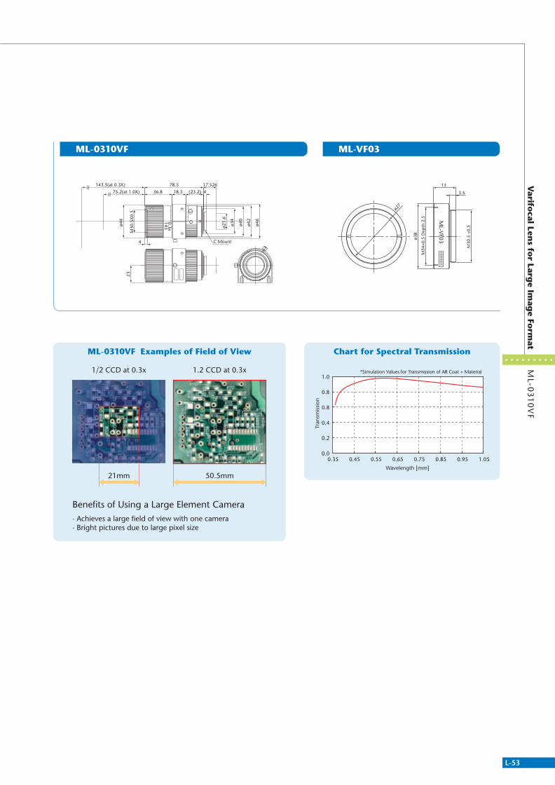
L-53
Varifo
cal Lens fo
r Large Im
age Fo
rmat
ML-0
31
0V
F
Chart for Spectral TransmissionML-0310VF Examples of Field of View
ML-0310VF ML-VF03
*Simulation Values for Transmission of AR Coat + Material
0.350.0
0.2
0.4
0.8
0.8
1.0
0.45 0.55 0.65
Wavelength [mm]
Tran
smis
sion
0.75 0.85 0.95 1.05
1/2 CCD at 0.3x 1.2 CCD at 0.3x
21mm 50.5mm
Benefits of Using a Large Element Camera· Achieves a large field of view with one camera· Bright pictures due to large pixel size
C Mount
143.5(at 0.3X)
75.2(at 1.0X)
ø44
M30
.5X
0.5
17.526
4
78.5
36.8 (23.2)18.5 4
ø42
ø21.
6
ø34
ø40
ø46
23
0.3x143
O
M34
×0.5
Dep
th 2
.5
ø27
13
3.5
ø38
M30
.5 ×
0.5
XXXXXXXX M
L-VF03
311766_MV_LensKatalog.indd 53 07.09.11 15:02
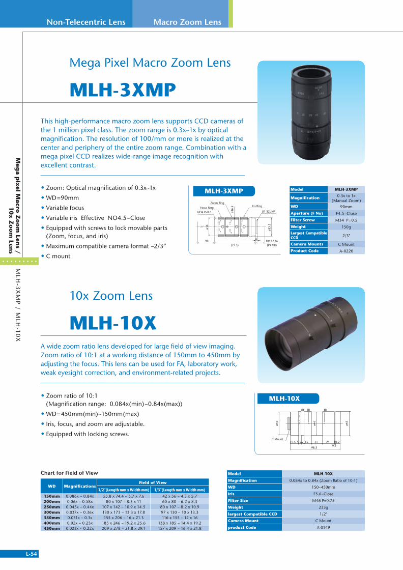
L-54
Non-Telecentric Lens Macro Zoom Lens
Meg
a pix
el Macro
Zo
om
Lens /
10x Z
oo
m Len
sM
LH-3
XM
P / M
LH-1
0X
Mega Pixel Macro Zoom Lens
MLH-3XMP
• Zoom: Optical magnification of 0.3x~1x
• WD=90mm
• Variable focus
• Variable iris Effective NO4.5~Close
• Equipped with screws to lock movable parts (Zoom, focus, and iris)
• Maximum compatible camera format ~2/3”
• C mount
• Zoom ratio of 10:1 (Magnification range: 0.084x(min)~0.84x(max))
• WD=450mm(min)~150mm(max)
• Iris, focus, and zoom are adjustable.
• Equipped with locking screws.
This high-performance macro zoom lens supports CCD cameras of the 1 million pixel class. The zoom range is 0.3x~1x by optical magnification. The resolution of 100/mm or more is realized at the center and periphery of the entire zoom range. Combination with a mega pixel CCD realizes wide-range image recognition with excellent contrast.
10x Zoom Lens
MLH-10XA wide zoom ratio lens developed for large field of view imaging. Zoom ratio of 10:1 at a working distance of 150mm to 450mm by adjusting the focus. This lens can be used for FA, laboratory work, weak eyesight correction, and environment-related projects.
ø48
ø46
98.5
C Mount15.5 65.5 15 21 25 10.2
0.3
ø46
Model MLH-3XMP
Magnification 0.3x to 1x (Manual Zoom)
WD 90mm
Aperture (F No) F4.5~Close
Filter Screw M34 P=0.5
Weight 150gLargest Compatible CCD 2/3"
Camera Mounts C Mount
Product Code A-0220
Model MLH-10X
Magnification 0.084x to 0.84x (Zoom Ratio of 10:1)
WD 150~450mm
Iris F5.6~Close
Filter Size M46 P=0.75
Weight 233g
largest Compatible CCD 1/2"
Camera Mount C Mount
product Code A-0149
Chart for Field of View
WD MagnificationsField of View
1/2”(Length mm x Width mm) 1/3”(Length mm x Width mm)
150mm 0.086x ~ 0.84x 55.8 x 74.4 ~ 5.7 x 7.6 42 x 56 ~ 4.3 x 5.7200mm 0.06x ~ 0.58x 80 x 107 ~ 8.3 x 11 60 x 80 ~ 6.2 x 8.3250mm 0.045x ~ 0.44x 107 x 142 ~ 10.9 x 14.5 80 x 107 ~ 8.2 x 10.9300mm 0.037x ~ 0.36x 130 x 173 ~ 13.3 x 17.8 97 x 130 ~ 10 x 13.3350mm 0.031x ~ 0.3x 155 x 206 ~ 16 x 21.3 116 x 155 ~ 12 x 16400mm 0.02x ~ 0.25x 185 x 246 ~ 19.2 x 25.6 138 x 185 ~ 14.4 x 19.2450mm 0.023x ~ 0.22x 209 x 278 ~ 21.8 x 29.1 157 x 209 ~ 16.4 x 21.8
MLH-10X
ø35.
5
ø36.
5
Zoom Ringø3
6
U1-32UNF
Iris RingFocus Ring
M34 P=0.5
4FB17.526(IN AIR)(77.5)
90
MLH-3XMP
311766_MV_LensKatalog.indd 54 07.09.11 15:02
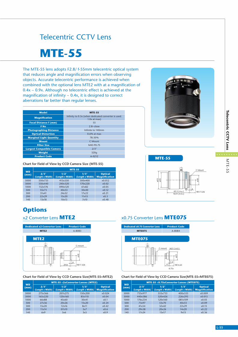
L-55
Telecentric C
CT
V Len
sM
TE-5
5
Options
The MTE-55 lens adopts F2.8/ f-55mm telecentric optical system that reduces angle and magnification errors when observing objects. Accurate telecentric performance is achieved when combined with the optional lens MTE2 with at a magnification of 0.4x ~ 0.9x. Although no telecentric effect is achieved at the magnification of infinity ~ 0.4x, it is designed to correct aberrations far better than regular lenses.
Telecentric CCTV Lens
MTE-55
MTE2 MTE075
x2 Converter Lens MTE2 x0.75 Converter Lens MTE075
MTE-55ø5
3ø4
5
ø30
65.5 ( )92.9 ( 0.5×)
FB17.526
C Mount
4
Model MTE-55
MagnificationInfinity to 0.5x (when dedicated converter is used.
1.0x at max) Focal Distance f (mm) 55
F No 2.8~close
Photographing Distance Infinite to 140mm
Oprical Distortion 0.6% at max
Marginal Light Quantity 78.50%
Mount C Mount
Filter Size M43 P0.75
Largest Compatible Camera 2/3"
Weight 320g
Product Code A-0212
Chart for Field of View by CCD Camera Size(MTE-55+MTE2)
WD(mm)
MTE-55 +2xConverter Lenses (MTE2)
2/3" (Length x Width)
1/2" (Length x Width)
1/3" (Length x Width)
Optical Magnification
5000 275x366 207x275 150x200 x0.0243000 165x220 120x160 85x110 x0.041000 66x88 45x60 30x41 x0.1500 27x36 20x26 15x20 x0.24300 15x20 12x16 8x11 x0.42200 11x14 07x10 5x7 x0.6140 6x9 5x6 3x5 x0.9
Chart for Field of View by CCD Camera Size (MTE-55)
WD(mm)
MTE-55
2/3" (Length x Width)
1/2" (Length x Width)
1/3" (Length x Width)
Optical Magnification
5000 550x733 415x550 300x400 x0.0123000 330x440 240x320 170x220 x0.021000 132x176 090x120 61x82 x0.05500 55x73 40x53 30x40 x0.12300 31x41 24x32 17x22 x0.21200 22x29 15x20 11x15 x0.3140 13x18 10x13 7x10 x0.48
Chart for Field of View by CCD Camera Size(MTE-55+MTE075)
WD(mm)
MTE-55 +0.75xConverter Lenses (MTE075)
2/3" (Length x Width)
1/2" (Length x Width)
1/3" (Length x Width)
Optical Magnification
5000 733x977 553x733 400x533 x0.0093000 440x586 320x426 226x293 x0.0151000 176x234 120x160 081x109 x0.03500 73x97 53x70 40x53 x0.09300 41x54 32x42 22x29 x0.15200 29x38 20x26 14x20 x0.22140 17x24 13x17 9x13 x0.36
C-mount
ø30
2×
FB17.52629.84
C-mount
ø23
0.75×
M21.5×0.5
FB14.63131.6
Dedicated x2 Converter Lens Product Code
MTE2 A-8083
Dedicated x0.75 Converter Lens Product Code
MTE075 A-8084
311766_MV_LensKatalog.indd 55 07.09.11 15:02

L-56
Non-Telecentric Lens
3 M
ega P
ixel C
CT
V Len
s
CCTV Lens
ML-M
P3 • High resolving power of 3 mega pixels or higher
• Supports 2/3" lenses
• Close distance (0.2 meters or greater) design suitable for machine vision
• Low distortion : 0.1% or less
• High image quality through improved marginal light quantity ratio
• Includes focus lock screws and iris lock screws
• Lens OD: 29mm
• Uniform fi lter mount M27 P0.5
3 Mega Pixel CCTV Lens
ML-MP3 Series
ML-M1620MP3 ML-M2518MP3 ML-M3520MP3 ML-M5028MP3
The ML-MP and ML-MP3 Mega Pixel CCTV Series are lenses developed for wide view image recognition with higher defi nition. The ability of the lenses to realize a resolution of higher than 100lp/mm both at the center and periphery when imaging at close distances is a particularly strong feature. In combination with a mega pixel camera, imaging with higher resolution and contrast than conventional CCTV lenses is achieved. With all models, the variable iris and focus can be set with locking screws as needed(*1). The lenses also support small FOV imaging when combined with close-up rings andrear converter lenses(*2).
The 3 Mega Pixel (ML-MP3) Series is our newest lineup of high end CCTV lenses addressing the needs of applications using high pixel count image sensors.
(*1) Vibration resistance is not considered in design.(*2) If a close-up ring and a rear converter lens are used, individual
differences in product performance, or image deterioration occurs due to an enlargement of lens tolerance.
(Images must be checked when using the lenses. Contact us if uncertain.) Note: Product performance is guaranteed only if the product is used
without additional attachments.
(IN AIR)
(33.5~36.8)
17.526
33.5
ø28.
5
ø29
4
M27×0.5
Focus Ring Iris Ring
C Mount
(36.4~40.7)
17.526
(.9)436.4
ø28.
5
ø29
ø20
(IN AIR)M27×0.5
Focus RingIris Ring
C Mount
(37.3~44.6)
17.526
437.3
ø28.
5
ø29
(IN AIR)M27×0.5
Focus RingIris Ring
C Mount
(45.4~52.7)
17.526
445.4
ø28.
5
ø29
(IN AIR)M27×0.5
Focus RingIris Ring
C Mount
Fixed Aperture / Focus Lock Type
Support for Special Orders
Model Focal Distance F No Field of View(HxV)
Closest Distance Filter Screw Weight Largest
compatible CCD Mount Product Code
ML-M1620MP3 16mm F2.0 - 16 23.3° x 30.7° 0.2m M27 P0.5 53g 2/3" C mount A-0229ML-M2518MP3 25mm F1.8 - 16 15° x 19.9° 0.2m M27 P0.5 60g 2/3" C mount A-0230ML-M3520MP3 35mm F2.0 - 16 10.7° x 14.3° 0.2m M27 P0.5 59g 2/3" C mount A-0231ML-M5028MP3 50mm F2.8 - 16 7,5° x 10.0° 0.2m M27 P0.5 69g 2/3" C mount A-0232
311766_MV_LensKatalog.indd 56 07.09.11 15:03

L-57
ML-M
PM
ega P
ixel C
CT
V Len
s
ML-M2514MP
ML-H0514MP
ML-M3514MP
ML-M0814MP
ML-M5018MP
ML-M1214MP
ML-M7528MP
ML-M1614MP
Mega Pixel CCTV Lens
ML-MP Series
• Lineup of 6 models (f = 5~50mm)
• Compatible with mega pixel cameras
• Variable focus and iris
• Equipped with screws to lock movable parts (focus and iris)
• Maximum compatible camera format ~2/3”
• C mount
Compact CCTV lenses with high resolution design for use with 1 mega pixel or higher count sensors.
364
17.526
ø16
ø32
ø32
ø33.
5
(1.1)
(36~40.9)
M30.5 P0.5
Focus Ring Iris RingIndex Ring
1/32 UNF(C Mount)
417.526
(3)
ø44.
5
45.5
ø20
ø32
(45.5~46.8)
M43 P0.75Focus Ring Iris Ring
Index Ring
1/32 UNF(C Mount)
(IN AIR)3.39.3 4
17.526
7.4
38.2
12
ø33.
5ø3
2
(6.2)
ø32
.4
141
86
C
17.5264 (0.6)
28.2
ø32
ø33.
5
ø18
ø32
(28.2~29.5)
M30.5 P0.5
Focus Ring Iris RingIndex Ring
1/32 UNF(C Mount)
4 (0.9)17.52638.2
ø16
ø32
ø32
ø33.
5
(38.2~43.1)
M30.5 P0.5
Focus Ring Iris RingIndex Ring
1/32 UNF(C Mount)
17.5264 (0.8)
28.2
ø32
ø33.
5
ø18
ø32
(28.2~29.5)
M30.5 P0.5
Focus Ring Iris RingIndex Ring
1/32 UNF(C Mount)
ø17.
5
ø32
(4 )(10.35)
ø35
ø32
414.615.2 3.3
17.52657.75
14.3
53.5( )(1.2m) (IN AIR)
4.82
C8
16
1 .2
ø18
ø32
17.5264 (0.9)
28.2
ø32
ø33.
5
(28.2~29.5)
M30.5 P0.5
Focus Ring Iris RingIndex Ring
1/32 UNF(C Mount)
Model Focal Distance F No Field of
View(HxV) Closest Distance Filter Screw Weight Largest compatible CCD Mount Product
CodeML-H0514MP 5mm F1.4 - 16C 51.4° x 65.5° 0.3m M43 P0.75 107g 1/2" C mount A-3100ML-M0814MP 8mm F1.4 - 16C 43.7° x 56.3° 0.1m M30.5 P0.5 70g 2/3" C mount A-0221ML-M1214MP 12mm F1.4 - 16C 30.8° x 40.4° 0.15m M30.5 P0.5 65g 2/3" C mount A-0222ML-M1614MP 16mm F1.4 - 16C 23.4° x 30.8° 0.3m M30.5 P0.5 65g 2/3" C mount A-0223ML-M2514MP 25mm F1.4 - 16C 15.1° x 20° 0.3m M30.5 P0.5 75g 2/3" C mount A-0224ML-M5018MP 50mm F1.8 - 16C 7.9° x 10.5° 0.5m M30.5 P0.5 90g 2/3" C mount A-0225
311766_MV_LensKatalog.indd 57 07.09.11 15:03

L-58
Non-Telecentric Lens
ML
CC
TV
Lens
CCTV Lens
ML-0614
ML-1614
ML-5018
ML-1214
ML-3519
ML-10035
ML-0813
ML-2514
ML-7527
CCTV Lens
ML Series
• A wide range of products from f=6mm to 100mm.
• Variable focus and iris equipped with lock screws.
• Camera mount: C mount
CCTV (Closed Circuit Television) lenses were developed to recognize images in a wide field of view. With all models, the variable iris and focus can be set with locking screws as needed.(*1) The lenses also support micro imaging in combination with close-up ring and rear converter lenses.(*2)
(*1) Vibration resistance is not considered in design.
(*2) Image quality may be distorted with enlargement of lens tolerance.
ø30
C M
ount
30 17.52
6.5
ø30
ø16
M27
× 0
.5
ø29.
3
24.5 17.52
4 1.4
C M
ount
37 17.52
4
ø32
M30
.5 ×
0.5
C M
ount
C M
ount
ø29.
4
17.5234.5
ø30
ø29.
3M
27.P
=0.5
C Mount
ø16
ø30
M27
P0.
5
4
4.8
(29) 17.53
Iris Locking Screw
Focus Locking Screw
C M
ount
(43.9) 17.52
ø29.
4
ø20.
5
4
2.4
M30
.5, P
=0.5
ø32
ø30
M25
.5 P
0.5
ø28
(34.5) 17.526
46.8
ø15
C M
ount
1.32
UN
F
ø29
m
841
21.3�
TV L
ENS
8mm
1:1.
3
C
0.5
16
0B
ø30
ø29.
3
ø17
24.5 17.52
4 1.6
M27
× 0
.5
C M
ount
C M
ount
42.5 17.52
ø29.
4
ø20.
5
4
2.5
M30
.5, P
=0.5
ø32
Model Focal Distance F No Field of View(HxV) Closest Distance Filter Screw Weight Largest
compatible CCD Mount Product Code
ML-0614 6mm F1.4 - close 42.3° x 54.6° 0.2m M27 P0.5 60g 1/2" C mount A-0198ML-0813 8mm F1.3 - close 45.0° x 57.8° 0.2m M25.5 P0.5 60g 2/3" C mount A-0199ML-1214 12mm F1.4 - close 21.9° x 29.0° 0.3m M27 P0.5 60g 1/2" C mount A-0200ML-1614 16mm F1.4 - close 23.0° x 30.4° 0.4m M27 P0.5 40g 2/3" C mount A-0201ML-2514 25mm F1.4 - close 21.6° x 28.5° 0.5m M27 P0.5 45g 1" C mount A-0202ML-3519 35mm F1.9 - close 10.8° x 14.4° 0.5m M27 P0.5 50g 2/3" C mount A-0203ML-5018 50mm F1.8 - close 7.9° x 10.5° 1m M30.5 P0.5 60g 2/3" C mount A-0204ML-7527 75mm F2.7 - close 4.9° x 6.5° 1m M30.5 P0.5 65g 2/3" C mount A-0205ML-10035 100mm F3.5 - close 3.8° x 5.1° 1m M30.5 P0.5 65g 2/3" C mount A-0206
311766_MV_LensKatalog.indd 58 07.09.11 15:03
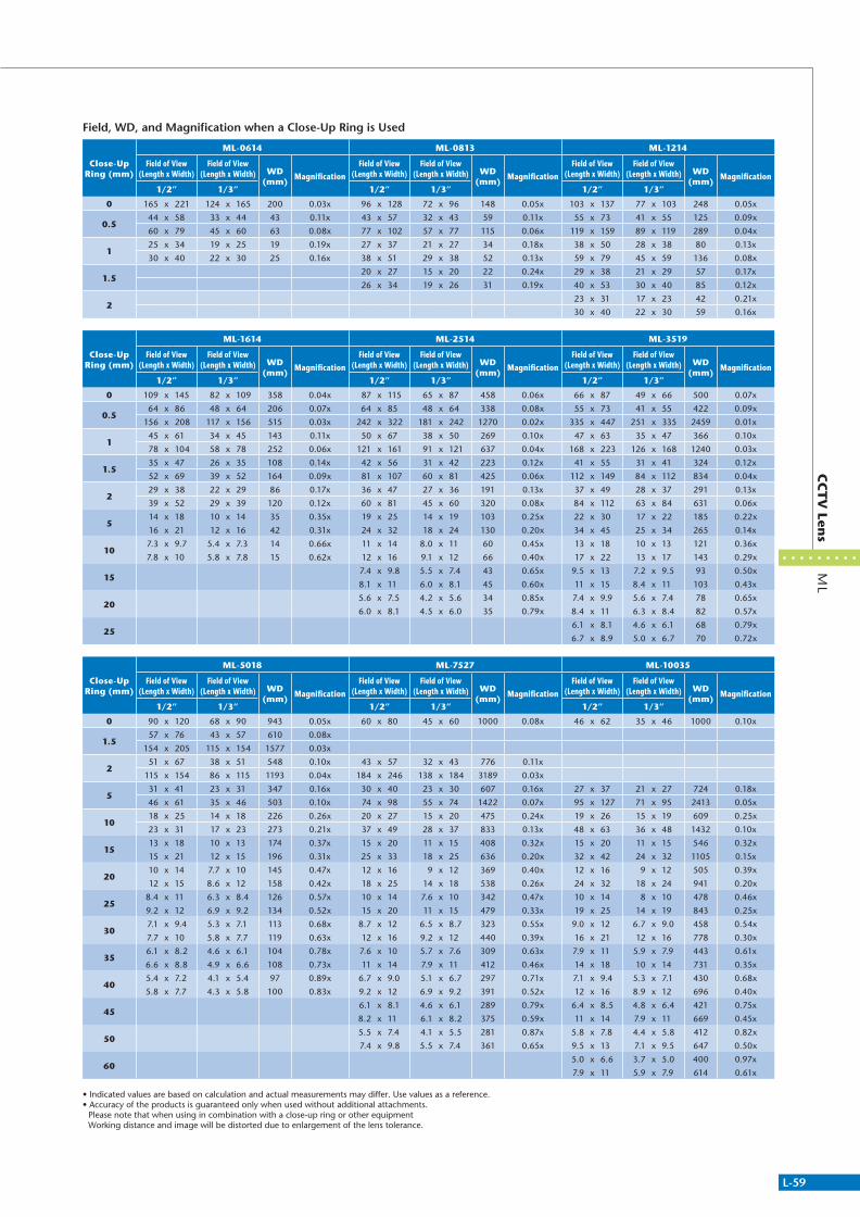
L-59
ML
CC
TV
Lens
Field, WD, and Magnification when a Close-Up Ring is Used
Close-Up Ring (mm)
ML-0614 ML-0813 ML-1214
Field of View (Length x Width)
Field of View (Length x Width) WD
(mm)Magnification
Field of View (Length x Width)
Field of View (Length x Width) WD
(mm)Magnification
Field of View (Length x Width)
Field of View (Length x Width) WD
(mm)Magnification
1/2” 1/3” 1/2” 1/3” 1/2” 1/3”
0 165 x 221 124 x 165 200 0.03x 96 x 128 72 x 96 148 0.05x 103 x 137 77 x 103 248 0.05x
0.544 x 58 33 x 44 43 0.11x 43 x 57 32 x 43 59 0.11x 55 x 73 41 x 55 125 0.09x
60 x 79 45 x 60 63 0.08x 77 x 102 57 x 77 115 0.06x 119 x 159 89 x 119 289 0.04x
125 x 34 19 x 25 19 0.19x 27 x 37 21 x 27 34 0.18x 38 x 50 28 x 38 80 0.13x
30 x 40 22 x 30 25 0.16x 38 x 51 29 x 38 52 0.13x 59 x 79 45 x 59 136 0.08x
1.520 x 27 15 x 20 22 0.24x 29 x 38 21 x 29 57 0.17x
26 x 34 19 x 26 31 0.19x 40 x 53 30 x 40 85 0.12x
223 x 31 17 x 23 42 0.21x
30 x 40 22 x 30 59 0.16x
Close-Up Ring (mm)
ML-1614 ML-2514 ML-3519
Field of View (Length x Width)
Field of View (Length x Width) WD
(mm)Magnification
Field of View (Length x Width)
Field of View (Length x Width) WD
(mm)Magnification
Field of View (Length x Width)
Field of View (Length x Width) WD
(mm)Magnification
1/2” 1/3” 1/2” 1/3” 1/2” 1/3”
0 109 x 145 82 x 109 358 0.04x 87 x 115 65 x 87 458 0.06x 66 x 87 49 x 66 500 0.07x
0.564 x 86 48 x 64 206 0.07x 64 x 85 48 x 64 338 0.08x 55 x 73 41 x 55 422 0.09x
156 x 208 117 x 156 515 0.03x 242 x 322 181 x 242 1270 0.02x 335 x 447 251 x 335 2459 0.01x
145 x 61 34 x 45 143 0.11x 50 x 67 38 x 50 269 0.10x 47 x 63 35 x 47 366 0.10x
78 x 104 58 x 78 252 0.06x 121 x 161 91 x 121 637 0.04x 168 x 223 126 x 168 1240 0.03x
1.535 x 47 26 x 35 108 0.14x 42 x 56 31 x 42 223 0.12x 41 x 55 31 x 41 324 0.12x
52 x 69 39 x 52 164 0.09x 81 x 107 60 x 81 425 0.06x 112 x 149 84 x 112 834 0.04x
229 x 38 22 x 29 86 0.17x 36 x 47 27 x 36 191 0.13x 37 x 49 28 x 37 291 0.13x
39 x 52 29 x 39 120 0.12x 60 x 81 45 x 60 320 0.08x 84 x 112 63 x 84 631 0.06x
514 x 18 10 x 14 35 0.35x 19 x 25 14 x 19 103 0.25x 22 x 30 17 x 22 185 0.22x
16 x 21 12 x 16 42 0.31x 24 x 32 18 x 24 130 0.20x 34 x 45 25 x 34 265 0.14x
107.3 x 9.7 5.4 x 7.3 14 0.66x 11 x 14 8.0 x 11 60 0.45x 13 x 18 10 x 13 121 0.36x
7.8 x 10 5.8 x 7.8 15 0.62x 12 x 16 9.1 x 12 66 0.40x 17 x 22 13 x 17 143 0.29x
157.4 x 9.8 5.5 x 7.4 43 0.65x 9.5 x 13 7.2 x 9.5 93 0.50x
8.1 x 11 6.0 x 8.1 45 0.60x 11 x 15 8.4 x 11 103 0.43x
205.6 x 7.5 4.2 x 5.6 34 0.85x 7.4 x 9.9 5.6 x 7.4 78 0.65x
6.0 x 8.1 4.5 x 6.0 35 0.79x 8.4 x 11 6.3 x 8.4 82 0.57x
256.1 x 8.1 4.6 x 6.1 68 0.79x
6.7 x 8.9 5.0 x 6.7 70 0.72x
Close-Up Ring (mm)
ML-5018 ML-7527 ML-10035
Field of View (Length x Width)
Field of View (Length x Width) WD
(mm)Magnification
Field of View (Length x Width)
Field of View (Length x Width) WD
(mm)Magnification
Field of View (Length x Width)
Field of View (Length x Width) WD
(mm)Magnification
1/2” 1/3” 1/2” 1/3” 1/2” 1/3”
0 90 x 120 68 x 90 943 0.05x 60 x 80 45 x 60 1000 0.08x 46 x 62 35 x 46 1000 0.10x
1.557 x 76 43 x 57 610 0.08x
154 x 205 115 x 154 1577 0.03x
251 x 67 38 x 51 548 0.10x 43 x 57 32 x 43 776 0.11x
115 x 154 86 x 115 1193 0.04x 184 x 246 138 x 184 3189 0.03x
531 x 41 23 x 31 347 0.16x 30 x 40 23 x 30 607 0.16x 27 x 37 21 x 27 724 0.18x
46 x 61 35 x 46 503 0.10x 74 x 98 55 x 74 1422 0.07x 95 x 127 71 x 95 2413 0.05x
1018 x 25 14 x 18 226 0.26x 20 x 27 15 x 20 475 0.24x 19 x 26 15 x 19 609 0.25x
23 x 31 17 x 23 273 0.21x 37 x 49 28 x 37 833 0.13x 48 x 63 36 x 48 1432 0.10x
1513 x 18 10 x 13 174 0.37x 15 x 20 11 x 15 408 0.32x 15 x 20 11 x 15 546 0.32x
15 x 21 12 x 15 196 0.31x 25 x 33 18 x 25 636 0.20x 32 x 42 24 x 32 1105 0.15x
2010 x 14 7.7 x 10 145 0.47x 12 x 16 9 x 12 369 0.40x 12 x 16 9 x 12 505 0.39x
12 x 15 8.6 x 12 158 0.42x 18 x 25 14 x 18 538 0.26x 24 x 32 18 x 24 941 0.20x
258.4 x 11 6.3 x 8.4 126 0.57x 10 x 14 7.6 x 10 342 0.47x 10 x 14 8 x 10 478 0.46x
9.2 x 12 6.9 x 9.2 134 0.52x 15 x 20 11 x 15 479 0.33x 19 x 25 14 x 19 843 0.25x
307.1 x 9.4 5.3 x 7.1 113 0.68x 8.7 x 12 6.5 x 8.7 323 0.55x 9.0 x 12 6.7 x 9.0 458 0.54x
7.7 x 10 5.8 x 7.7 119 0.63x 12 x 16 9.2 x 12 440 0.39x 16 x 21 12 x 16 778 0.30x
356.1 x 8.2 4.6 x 6.1 104 0.78x 7.6 x 10 5.7 x 7.6 309 0.63x 7.9 x 11 5.9 x 7.9 443 0.61x
6.6 x 8.8 4.9 x 6.6 108 0.73x 11 x 14 7.9 x 11 412 0.46x 14 x 18 10 x 14 731 0.35x
405.4 x 7.2 4.1 x 5.4 97 0.89x 6.7 x 9.0 5.1 x 6.7 297 0.71x 7.1 x 9.4 5.3 x 7.1 430 0.68x
5.8 x 7.7 4.3 x 5.8 100 0.83x 9.2 x 12 6.9 x 9.2 391 0.52x 12 x 16 8.9 x 12 696 0.40x
456.1 x 8.1 4.6 x 6.1 289 0.79x 6.4 x 8.5 4.8 x 6.4 421 0.75x
8.2 x 11 6.1 x 8.2 375 0.59x 11 x 14 7.9 x 11 669 0.45x
505.5 x 7.4 4.1 x 5.5 281 0.87x 5.8 x 7.8 4.4 x 5.8 412 0.82x
7.4 x 9.8 5.5 x 7.4 361 0.65x 9.5 x 13 7.1 x 9.5 647 0.50x
605.0 x 6.6 3.7 x 5.0 400 0.97x
7.9 x 11 5.9 x 7.9 614 0.61x
• Indicated values are based on calculation and actual measurements may differ. Use values as a reference.• Accuracy of the products is guaranteed only when used without additional attachments. Please note that when using in combination with a close-up ring or other equipment Working distance and image will be distorted due to enlargement of the lens tolerance.
311766_MV_LensKatalog.indd 59 07.09.11 15:03

L-60
Non-Telecentric Lens
ML-X
Rear C
on
verter Lens
Accessory
Rear Converter Lens
ML-X
Attaching these lenses between a CCTV lens and a CCD camera enables the adjustment of magnification without changing the working distance of the system.*May decrease the resolution.
ML-1.5X
ML-3X
ML-2X
ML-4X
ML-2.5X
Configuration
Lens Rear Converter Lens CCD Camera
Model Product Code
ML-1.5X A-8090
ML-2X A-8091
ML-2.5X A-8092
ML-3X A-8093
ML-4X A-8094
ø30
ø21
C Mount
C Mount
11.7
5
ø30
ø29.4
ø11
22.7
17.5
240.
6
C Mount
C Mount
ø29.4
13.36.
9
ø30 Knurl
C Mount
C Mount
ø30
ø29.4
30.2
17.5
24
C Mount
C Mount
ø29.4
15.611
.6
ø30 Knurl
C Mount
C Mount
311766_MV_LensKatalog.indd 60 07.09.11 15:03

L-61
Filter Attachment ScrewM30.5
CCTV Attachment Screw2 types included for use with M25.5 and M27
ML-MLC
Illumination Bracket
MLA-DR31M305MLA-SCM305
ML-PL305
Color Filter
Cover Glass
Polarizer Filter
ML-R60-30ML-R64-30
ML-GA305
ML-M
LC90° M
irror P
rism
90° Mirror Prism
ML-MLC
• Fully supports CCTV M25.5, 27, and 30.5.
• Equipped with screws to attach filters.
Model Product Code
ML-MLC A-8014
ML-MLC
CCTVAttachmentBracket
CCTV Attachment BracketM25.5, M27 Included
0 Type M2 PanHead ScrewNot Yet Attached
Filter Plate(Detachable)
Serial Number Label
M2 HexagonalSocket HeadLocking Screw4 Places
1
M25
.5×0
.5
2.51 2.5
M27
×0.5
34
16
3
M30.5×0.5
22
39 2.5
M30
.5×0
.5
3.8
10.7 1
32
32
311766_MV_LensKatalog.indd 61 07.09.11 15:03

L-62
Non-Telecentric Lens
ML-G
A / M
L-PL / M
L-FL / ML-E
XR
Op
tion
s for C
CT
V Len
s
Accessory / SOD-III
A cover glass adapter for preventing the adhesion of dirt and foreign objects to the lens surface.
Used when using the CCTV lens at a close distance or when enlarging the magnification.See comparison table on page P.L-63 for the field of view, working distance, and magnification when close-up ring is attached.
Ring illumination adapter ML-FL.A polarizer (analyzer) adapter with revolution function for suppressing glare from objects and localized flare when used as a set with polarizer illumination.
ML-GA Series ML-PL Series ML-FL Series
ML-EXR Series
Glass Covers Polarizers (Analyzers) Ring Illumination Attachment Adapters
Close-Up Ring
Options for CCTV Lenses
Options
Screw Pitch255 270 305
Model Product Code Model Product Code Model Product Code
Glass Covers ML-GA255 A-8059 ML-GA270 A-8060 ML-GA305 A-8061
Polarizer ML-PL255 A-8067 ML-PL270 A-8068 ML-PL305 A-8069
Polarizer (With Locking Screw) ML-PL255LB A-3130 ML-PL270LB A-3131 ML-PL305LB A-3132
Red Filter ML-R60-25 A-8031 ML-R60-27 A-8032 ML-R60-30 A-8033
Sharp Cut Filter ML-R64-25 A-9055 ML-R64-27 A-9056 ML-R64-30 A-9057
Close-Up Ring ML-EXR
Model Remarks Product Code
ML-EXR Set of 7 (0.5, 1, 2, 5, 10, 20, 40) A-8100
ML-EXR05 0.5mm A-8101
ML-EXR1 1mm A-8102
ML-EXR2 2mm A-8103
ML-EXR5 5mm A-8104
ML-EXR10 10mm A-8105
ML-EXR15 15mm A-8106
ML-EXR20 20mm A-8107
ML-EXR25 25mm A-8108
ML-EXR30 30mm A-8109
ML-EXR40 40mm A-8110
ML-EXR50 50mm A-8111
ML-EXR100 100mm A-8112
ML-EXR1520 Variable Type (15 to 20 mm) A-8113
ML-EXR3042 Variable Type (30 to 42 mm) A-8114
311766_MV_LensKatalog.indd 62 07.09.11 15:03

L-63
SO
D-III
Co
axial Ep
i-illum
inatio
n U
nit
for O
bjective Len
s
• Compact design
• Compatible with various bright field lenses
• Enables horizontal and various other kinds of mountings
The SOD-III is an optical unit used for coaxial illumination with objective lenses. If you are using a metallurgical microscope, this unit is effective for image input because it produces video of the same level. It is designed for infinity corrected objective lenses (bright vision) and can be used with the lenses listed below. In addition to the monocular type, the 5-hole revolver type (manual and electric) is available, which can be mounted with 5 objective lenses,
Compact Objective Lens
Coaxial Epi-illumination Unit for Objective Lens
SOD-III Series
SOD-III
65 41
ø30ø30
ø16ø8
ø32
4-M3 Depth 4
26 12
8816
017
.526
C Mount
�36
35
4916
.916
410
14
MSG4-1100S, etc.
23.6
24.5
L
N/O:L=6 ø29.5M:L=7.5 ø33
Mitsutoyo
Model NA WD (mm) Product Code
M Plan Apo 2 x 0.055 34 A-8132M Plan Apo 5 x 0.14 34 A-8133M Plan Apo 10 x 0.28 33.5 A-8134M Plan Apo 20 x 0.42 20 A-8137M Plan Apo SL 20 x 0.28 30.5 A-8135M Plan Apo SL 50 x 0.42 20.5 A-8136
Nikon
Model NA WD (mm) Product Code
CF IC EPI Plan 2.5 x 0.075 8.8 A-8143CF IC EPI Plan 5 x 0.13 22.5 A-8144CF IC EPI Plan 10 x A 0.3 16.5 A-8148CF IC EPI SLWDPlan 10 x A 0.21 20.3 A-8145CF IC EPI SLWDPlan 20 x A 0.35 20.5 A-8146CF IC EPI SLWDPlan 50 x A 0.45 13.8 A-8147
Model Product Code
SOD-III A-0171
311766_MV_LensKatalog.indd 63 07.09.11 15:03

L-64
Non-Telecentric Lens
311766_MV_LensKatalog.indd 64 07.09.11 15:03

Line Scan Lens forLine & Large Format Sensors
With the increasing number of line scan and large format applications, we have continued to expand our product offering beyond the compact telecentric lenses that have become an industry standard for area scan applications. We offer an assorted range of lens solutions designed for large format high resolution line and area scan cameras used for Glass, Web, TFT inspection and other applications which call for a high performance and low distortion lens. Our models support line image sensors from 2k to 12k with models compatible up to 90 mm wide and a pixel pitch of down to 5 μm.
L-65
Line Scan
Lens fo
r Line &
Large Fo
rmat Sen
sors
Up to 82mm
Up to 90mm
Image Format
Compatible Camera Pixel
Up to 62mm
Up to 58mm
Up to 35mm
5μm/Pixel
7μm/Pixel
10μm/Pixel
7µm
10µm
5µm
82mm
90mm
62mm
58mm
35mm
311766_MV_LensKatalog.indd 65 07.09.11 15:03
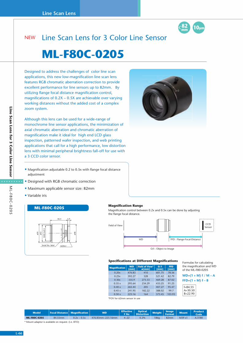
L-66
Line Scan Lens
ML-F8
0C
-02
05
Line Scan
Lens fo
r 3 C
olo
r Line Sen
sor
Line Scan Lens for 3 Color Line Sensor
ML-F80C-0205
10µm82mm
• Magnifi cation adjustable 0.2 to 0.5x with fl ange focal distance
adjustment
• Designed with RGB chromatic correction
• Maximum applicable sensor size: 82mm
• Variable iris
Designed to address the challenges of color line scan applications, this new low-magnifi cation line scan lens features RGB chromatic aberration correction to provide excellent performance for line sensors up to 82mm. By utilizing fl ange focal distance magnifi cation control, magnifi cations of 0.2X – 0.5X are achievable over varying working distances without the added cost of a complex zoom system.
Although this lens can be used for a wide-range of monochrome line sensor applications, the minimization of axial chromatic aberration and chromatic aberration of magnifi cation make it ideal for high end LCD glass inspection, patterned wafer inspection, and web printing applications that call for a high performance, low distortion lens with minimal peripheral brightness fall-off for use with a 3 CCD color sensor.
ø50
ø45
46.4 5.9
ø48
M40
.5x0
.5 FFFFFF
115.6
48
22
Serial No. label M39x1
ML-F80C-0205
Specifi cations at Different Magnifi cations
Magnifi cation WD(mm)
Field of View*ø(mm)
O/I (mm)
FFD(mm)
0.20x 476.83 410 601.75 78.560.25x 392.27 328 521.42 82.790.30x 335.9 273.33 469.28 87.020.35 x 295.64 234.29 433.25 91.250.40 x 265.44 205 407.27 95.470.45 x 241.95 182.22 388.02 99.70.50 x 223.16 164 373.45 103.93
*FOV for 62mm sensor in use
f=84.55A=30.50B=22.90
Formulas for calculating the magnifi cation and WD of the ML-F80-0205
WD=(1 + M) f / M – A
FFD=(1 + M) f – B
Field of View CCDSensor
WD FFD : Flange-Focal-Distance
O/I : Object to Image
Model Focal Distance Magnifi cation WD EffectiveF No
Optical Distortion Weight Image
Format Mount Product Code
ML-F80C-0205 84.55mm 0.2x ~ 0.5x 476.83mm~223.16mm 4~22 0.2% 186g 82mm M39 x1 A-3180
* Mount adaptor is available on request. (i.e. BTO)
NEW
Magnifi cation RangeMagnifi cation control between 0.2x and 0.5x can be done by adjusting the fl ange focal distance.
311766_MV_LensKatalog.indd 66 07.09.11 15:03

L-67
ML-L0
05
02
Line Scan
Lenses fo
r 62
mm
Senso
r
Line Scan Lens for 62mm Sensor
ML-L00502
• 0.05 to 0.2x magnifi cation
• WD from 1590 to 420mm
• Supports 62mm sensors
• F2.9
• High uniformity >80%
• Low distortion, <0.1%
• Variable iris
This new low-magnifi cation model ML-L series is suitable for of a wide range of applications with its adjusted magnifi cation of 0.05 to 0.2x and WD of 420 to 1,590 mm. It can be used with image sensors of up to ø62 mm and was designed for image processing that requires peripheral light volume ratio of 80% or more with optical distortion of 0.1% or less.The lens comes standard with a M72-FB31.8mm camera mount and optional mounting adapters such as M72-6.56/19.55 & TFL2 are available. Mounts for large format area scan cameras can also be provided.
Model Focal Distance Magnifi cation WD Effective F No Optical Distortion Weight Image Format Mount Product Code
ML-L00502 78mm 0.05x ~ 0.2x 1590mm ~ 420mm 2.9~16.5 0.1% - 62mm M72 FB31.8 A-3164
ML-L00502
WD1591 ±80 31.890.8
ø71
ø58
M72
x0.7
5
ø75
3.84 6 22 40
WD420 ±21 (O/I=554.4)
(O/I=1713.4)
102.2
3.8
31.8615.5 22 40
0.05x
0.2x
Effective F No 2.9~14.8
Aperture adjustment ring Zoom ring
Serial No. label
M72x0.75
7µm62mm
311766_MV_LensKatalog.indd 67 07.09.11 15:03
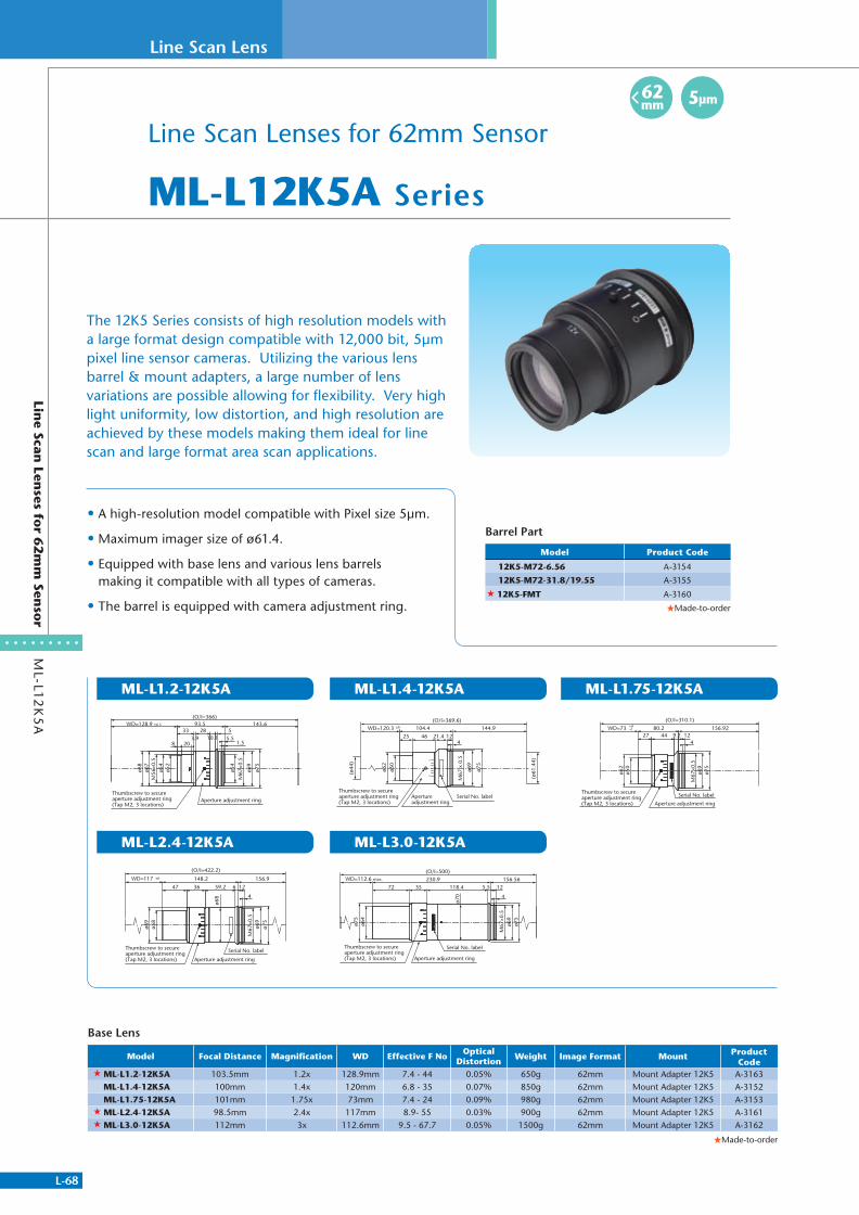
L-68
Line Scan Lens
ML-L1
2K
5A
Line Scan
Lenses fo
r 62
mm
Senso
r
Line Scan Lenses for 62mm Sensor
ML-L12K5A Series
• A high-resolution model compatible with Pixel size 5μm.
• Maximum imager size of ø61.4.
• Equipped with base lens and various lens barrels making it compatible with all types of cameras.
• The barrel is equipped with camera adjustment ring.
The 12K5 Series consists of high resolution models with a large format design compatible with 12,000 bit, 5μm pixel line sensor cameras. Utilizing the various lens barrel & mount adapters, a large number of lens variations are possible allowing for flexibility. Very high light uniformity, low distortion, and high resolution are achieved by these models making them ideal for line scan and large format area scan applications.
ML-L1.2-12K5A
ML-L2.4-12K5A
ML-L1.75-12K5AML-L1.4-12K5A
ML-L3.0-12K5A
WD=128.9 ±6.5 93.5 143.6(O/I=366)
ø54
ø52
M56
×0.5
ø67
ø68
ø54
M67
×0.5
ø69
ø75
33
8 20
283.9 10.1
5
1.55.5
Thumbscrew to secure aperture adjustment ring(Tap M2, 3 locations)
Aperture adjustment ring
WD=117 156.9
(O/I=422.2)
47 36 59.2 6 12
4
148.2
ø58
ø69
ø68
ø75
ø69
M67
×0.5
±6
Thumbscrew to secureaperture adjustment ring(Tap M2, 3 locations) Aperture adjustment ring
Serial No. label
WD=73
(O/I=310.1)
156.9227 44
ø50
ø62
80.212
4
M67
×0.5
ø69
ø75
9.2
+4-2
Serial No. label
Aperture adjustment ring
Thumbscrew to secureaperture adjustment ring(Tap M2, 3 locations)
OC
4
ø75
ø69
12
104.4(O/I=369.6)
(ø44
)
ø50
ø62
WD=120.3
4625 21.4
±6
M67
x 0
.5
(ø61
.44)
144.9
Thumbscrew to secureaperture adjustment ring(Tap M2, 3 locations)
Apertureadjustment ring
Serial No. label
12
WD=112.6 max. 156.56(O/I=500)
72 35 118.4 5.5
4
230.9
ø64
ø75
ø70
ø75
ø69
M67
×0.5
Thumbscrew to secureaperture adjustment ring(Tap M2, 3 locations) Aperture adjustment ring
Serial No. label
Barrel Part
Model Product Code
12K5-M72-6.56 A-3154
12K5-M72-31.8/19.55 A-3155
12K5-FMT A-3160
Made-to-order
Base Lens
Model Focal Distance Magnification WD Effective F No Optical Distortion Weight Image Format Mount Product
Code ML-L1.2-12K5A 103.5mm 1.2x 128.9mm 7.4 - 44 0.05% 650g 62mm Mount Adapter 12K5 A-3163
ML-L1.4-12K5A 100mm 1.4x 120mm 6.8 - 35 0.07% 850g 62mm Mount Adapter 12K5 A-3152 ML-L1.75-12K5A 101mm 1.75x 73mm 7.4 - 24 0.09% 980g 62mm Mount Adapter 12K5 A-3153
ML-L2.4-12K5A 98.5mm 2.4x 117mm 8.9- 55 0.03% 900g 62mm Mount Adapter 12K5 A-3161 ML-L3.0-12K5A 112mm 3x 112.6mm 9.5 - 67.7 0.05% 1500g 62mm Mount Adapter 12K5 A-3162
Made-to-order
5µm62mm
311766_MV_LensKatalog.indd 68 07.09.11 15:03

L-69
ML-L0
20
35
/03
50
5Lin
e Scan Len
ses for 5
7m
m Sen
sor
Line Scan Lenses for 57mm Sensor
ML-L02035/03505
• Advanced optical design for maximum 8000-bit (57.3mm)
• Advanced optical design for 1” mega pixel (2 million pixels~) area CCD
• Designed with variable magnification (0.2x~0.35x or 0.35x~0.5x)
• Low chromatic aberration and low distortion
• Designed for various mountings
These are high performance lenses for use with 8,000 pixel Line Scan CCDs with element length of 57.3mm. Flexibility is provided by the variable magnification and focus adjustment included. Outstanding performance is achieved by minimizing the chromatic aberration and distortion.
ML-L02035 ML-L03505
ø60
51.5
OC
Magnification Adjustment Screw
Aperture Adjustment Screw
1.718 (1.3~18.3)
3-M2.6 For Setting Mount
104.3(×0.2)~121.3(×0.35)WD 555.4 (×0.2)WD 345.6 (×0.35)
M46 P=0.75
ø60
51.5
18 (1.3~18.3)
121.3(×0.35)~138.3(×0.5)
M46 P=0.75
OC
1.7
WD 345.6 (×0.35)WD 261.8 (×0.5)
Magnification Adjustment Screw
Aperture Adjustment Screw 3-M2.6
For Setting Mount
Model Focal Distance Magnification WD Effective F No Optical Distortion Weight Image Format Mount Product
CodeML-L02035 100mm~101.6mm 0x2 ~ 0.35x 555.4mm ~ 345.6mm 5.8~36.6 0.1% 750g 58mm Mount Adapter MT-S A-0184ML-L03505 101.6mm~103mm 035 x~ 0.5x 345.6mm ~ 261.7mm 6.6~41 0.1% 800g 58mm Mount Adapter MT-S A-0185
7µm58mm
311766_MV_LensKatalog.indd 69 07.09.11 15:03

L-70
Line Scan Lens
ML-L
Line Scan
Lenses fo
r 35
mm
Senso
r
• Optimal for high speed processing of large fields of view.
• Low optical distortion, all models less than 0.1%
• Low marginal rays difference
• High resolution, high contrast
• Suitable for long working distance applications
ML-L05
ML-L047-200
ML-L07 ML-L09 ML-L14
Line Scan Lenses for 35mm Sensor
ML-L Series
122×0.5W.D 250.5
Aperture Adjustment Screw
3-M2.6×2.5Porcelain screw
ø60
303 1
ø49
ø50
−0.0
2−0
.07
Aperture Adjustment Screw
ø60
117.1
(O/I=377.6)
60.5W.D 200
(3)
1.5
0
−0.1
±6
M2.6-2.5 Porcelain Screw
L=35 Line CCD
144.5×0.7W.D 194
ø60
303 1
ø49
ø50
−0.0
2−0
.07
Aperture Adjustment Screw
3-M2.6×2.5 Porcelain Screw
170.5×0.93W.D 158.5
Aperture Adjustment Screw
ø60
303 1
ø49
ø50
−0.0
2−0
.07
3-M2.6×2.5 Porcelain Screw
237.3×1.4W.D 100
ø60
303
ø55
ø56
−0.0
2−0
.07
1 Aperture Adjustment Screw
3-M2.6×2.5 Porcelain Screw
Made-to-order
Model Focal Distance Magnification WD Effective F No Optical Distortion Weight Image Format Mount Product Code
ML-L05 102mm 0.5x 250.5mm 5.9 - 28 0.1% 700g 35mm Mount Adapter MT A-0179ML-L07 103mm 0.7x 194mm 6.7 - 32 0.1% 800g 35mm Mount Adapter MT A-0180ML-L09 104mm 0.933x 158.5mm 7.7 - 37 0.1% 800g 35mm Mount Adapter MT A-0181ML-L14 103mm 1.4x 100mm 9.5 - 45 0.1% 800g 35mm Mount Adapter MT A-0182ML-L047-200 95mm 0.47x 200mm 5.9 - 32 0.01% 720g 35mm Mount Adapter MT A-0183
* Depth of field is calculated based on resolution.* Resolution values indicate the theoretical resolution at a wavelength of 550nm.
7µm35mm
311766_MV_LensKatalog.indd 70 07.09.11 15:03
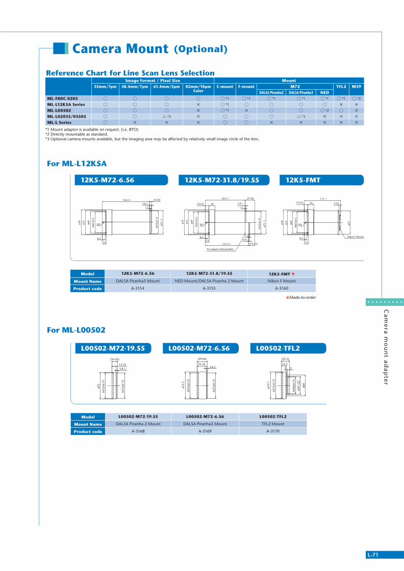
L-71
Ca
me
ra m
ou
nt a
da
pte
r
Camera Mount (Optional)
M67
x0.5
M72
x0.7
5
ø75
0 -0.1
ø69
ø79
ø75
138.5
125.1±5
(10.4) 20
(31.8)
3.8 0-0.1
3.8 0-0.1
1.5
(19.55)
1.5
137.4 ±5
P2 adapter (Detachable)
M3
3.8 0-0.1
1.5
M67
x0.5
ø69
ø75
M72
x0.7
5
150.4 ±5
ø79
(6.56)
8.5
13
M3 ø75
0 -0.1
ø79
115 ±5
20(10.4)
13
8.5
M3ø75
ø69
M67
x0.5
ø75
4.55
Nikon F Mount
Reference Chart for Line Scan Lens SelectionImage Format / Pixel Size Mount
35mm/7µm 58.4mm/7µm 61.4mm/5µm 82mm/10µm Color
C-mount F-mount M72 TFL2 M39DALSA Piranha2 DALSA Piranha3 NED
ML-F80C-0205 *1 *1 *1 *1 *1 *1 *2
ML-L12K5A Series *1
ML-L00502 *1 *2
ML-L02035/03505 *3 *3
ML-L Series
*1 Mount adaptor is available on request. (i.e. BTO)*2 Directly mountable as standard.*3 Optional camera mounts available, but the imaging area may be affected by relatively small image circle of the lens.
L00502-M72-19.55 L00502-M72-6.56 L00502-TFL2
For ML-L00502
For ML-L12K5A
3.8 -0.10
M72
x0.7
5
M72
x0.7
5
ø75
12.25
(16.05)
25.243.8 -0.1
0
(29.04)
M72
x0.7
5
M72
x0.7
5
ø75
-0.1
0
M72
x0.7
5
ø75
-0.1
0
M48
x0.7
5
ø60
3 5
14.3
ø50
-0.0
09-0
.025
(22.3)
12K5-M72-6.56 12K5-M72-31.8/19.55 12K5-FMT
Model 12K5-M72-6.56 12K5-M72-31.8/19.55 12K5-FMT
Mount Name DALSA Piranha3 Mount NED Mount/DALSA Piranha 2 Mount Nikon F Mount
Product code A-3154 A-3155 A-3160
Made-to-order
Model L00502-M72-19.55 L00502-M72-6.56 L00502-TFL2
Mount Name DALSA Piranha 2 Mount DALSA Piranha3 Mount TFL2 Mount
Product code A-3168 A-3169 A-3170
311766_MV_LensKatalog.indd 71 07.09.11 15:03
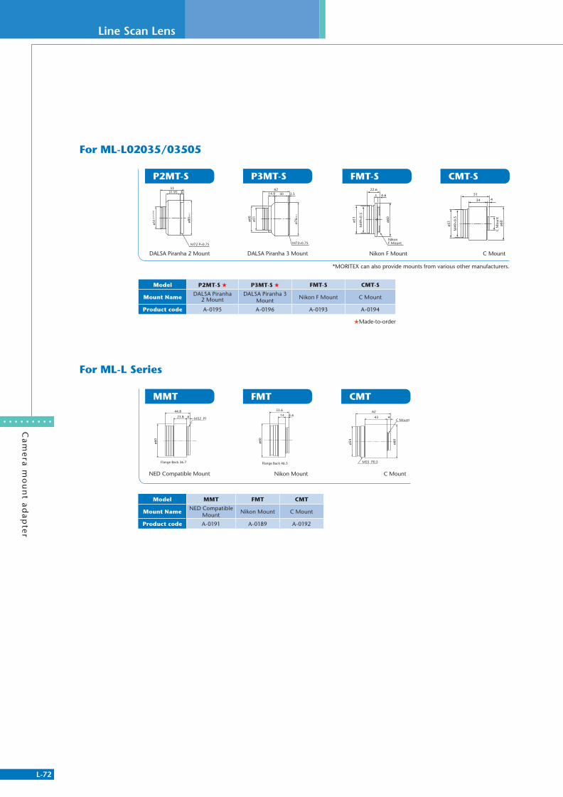
L-72
Line Scan Lens
Ca
me
ra m
ou
nt a
da
pte
r
Flange Back 36.7
M52 P1
ø60
44.8
23.8 6
Flange Back 46.5
33.6
ø60
14 4.6 43 4
62
ø60
ø54
M55 P0.5
C Mount
Model P2MT-S P3MT-S FMT-S CMT-S
Mount NameDALSA Piranha
2 Mount DALSA Piranha 3
MountNikon F Mount C Mount
Product code A-0195 A-0196 A-0193 A-0194
Made-to-order
*MORITEX can also provide mounts from various other manufacturers.
ø51-0
.01-
0.03
ø80
0-
0.1
5331.95 8
M72 P=0.75
DALSA Piranha 2 Mount
6214.9 30 3.5
M72×0.75
ø60
ø51
ø76
0-
0.1
DALSA Piranha 3 Mount
P2MT-S P3MT-S
NED Compatible Mount
MMT
ø51
ø60
22.6
4.65
M49
×0.5
Nikon F Mount
Nikon F Mount
C M
ount
ø51
ø60
M49
×0.5
34 451
C Mount
FMT-S CMT-S
Nikon Mount C Mount
FMT CMT
Model MMT FMT CMT
Mount NameNED Compatible
MountNikon Mount C Mount
Product code A-0191 A-0189 A-0192
For ML-L Series
For ML-L02035/03505
311766_MV_LensKatalog.indd 72 07.09.11 15:03

Partner Lens
L-73
Partn
er Lens
Carl ZeissVISIONMES®
311766_MV_LensKatalog.indd 73 07.09.11 15:03
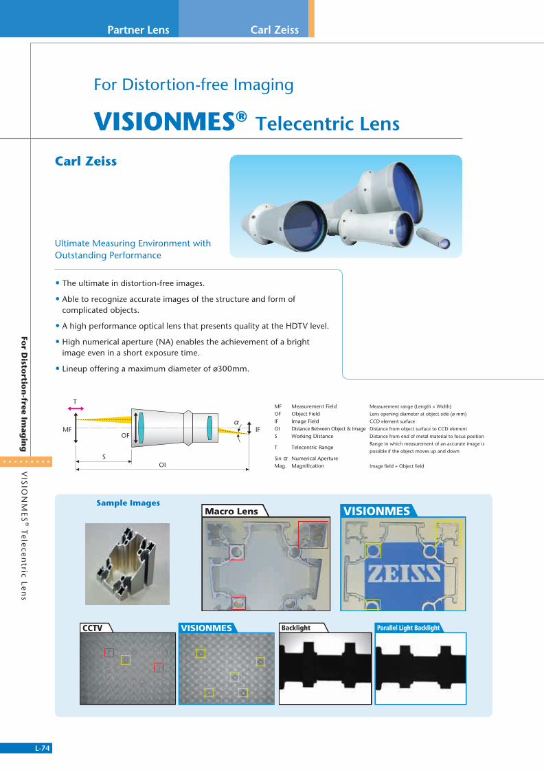
L-74
Partner Lens
VIS
ION
ME
S® Te
lece
ntric Le
ns
For D
istortio
n-free Im
agin
g
Carl Zeiss
For Distortion-free Imaging
VISIONMES® Telecentric Lens
• The ultimate in distortion-free images.
• Able to recognize accurate images of the structure and form of complicated objects.
• A high performance optical lens that presents quality at the HDTV level.
• High numerical aperture (NA) enables the achievement of a bright image even in a short exposure time.
• Lineup offering a maximum diameter of ø300mm.
Ultimate Measuring Environment with Outstanding Performance
Sample Images
Carl Zeiss
VISIONMESMacro Lens
VISIONMESCCTV Parallel Light BacklightBacklight
MFOFIFOIS
T
SinMag.
Measurement FieldObject FieldImage FieldDistance Between Object & ImageWorking Distance
Telecentric Range
Numerical ApertureMagnification
Measurement range (Length × Width)
Lens opening diameter at object side (ø mm)
CCD element surface
Distance from object surface to CCD element
Distance from end of metal material to focus position
Range in which measurement of an accurate image is
possible if the object moves up and down
Image field ÷ Object field
MF IFOF
T
SOI
311766_MV_LensKatalog.indd 74 07.09.11 15:03
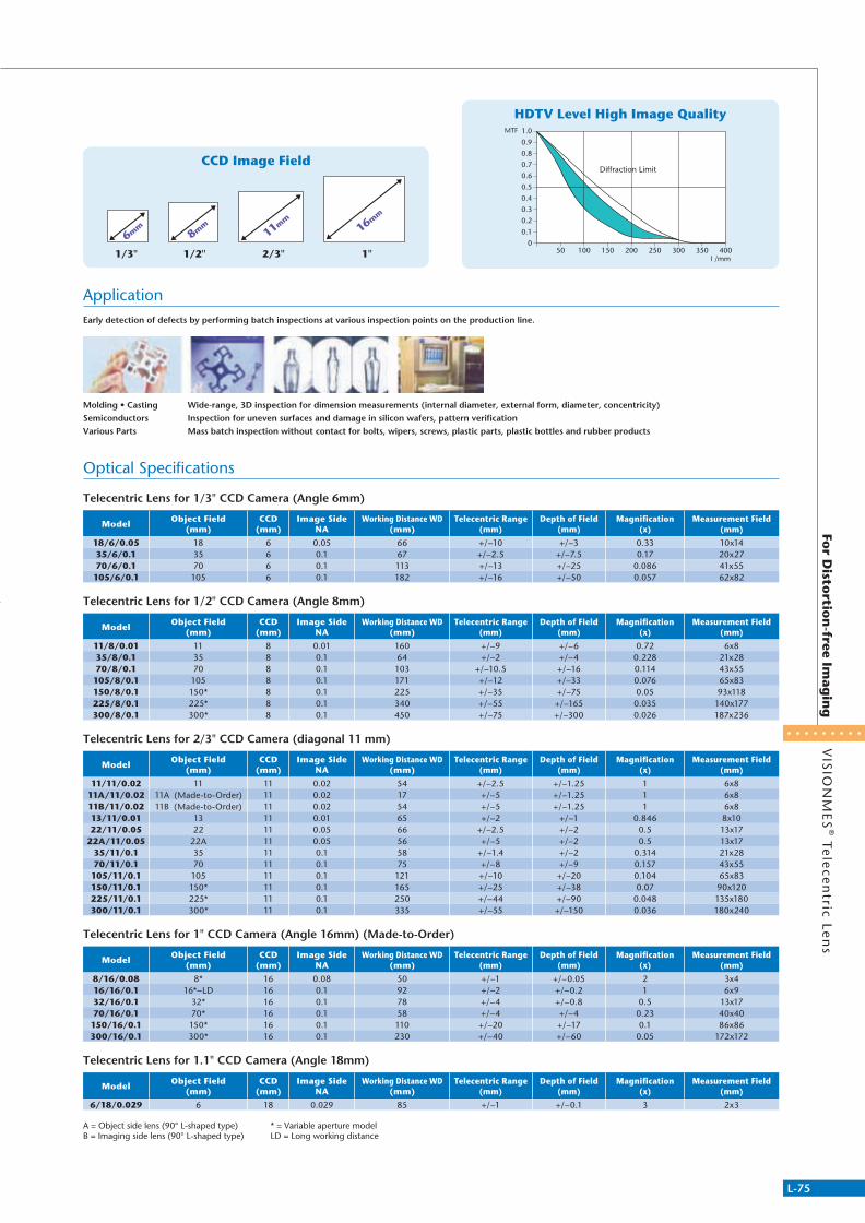
L-75
VIS
ION
ME
S® Te
lece
ntric Le
ns
For D
istortio
n-free Im
agin
g
Optical Specifications
ApplicationEarly detection of defects by performing batch inspections at various inspection points on the production line.
Molding • Casting Wide-range, 3D inspection for dimension measurements (internal diameter, external form, diameter, concentricity)Semiconductors Inspection for uneven surfaces and damage in silicon wafers, pattern verificationVarious Parts Mass batch inspection without contact for bolts, wipers, screws, plastic parts, plastic bottles and rubber products
MTF 1.0
0.9
0.8
0.7
0.6
0.5
0.4
0.3
0.2
0.1
050 100 150 200 250 300 350 400
l /mm
Diffraction Limit
1/3"
6mm
1/2"
8mm
2/3"
11mm
1"
16mm
HDTV Level High Image Quality
CCD Image Field
Telecentric Lens for 1/3" CCD Camera (Angle 6mm)
ModelObject Field
(mm)CCD
(mm)Image Side
NAWorking Distance WD
(mm)Telecentric Range
(mm)Depth of Field
(mm)Magnification
(x)Measurement Field
(mm)
18/6/0.05 18 6 0.05 66 +/−10 +/−3 0.33 10x1435/6/0.1 35 6 0.1 67 +/−2.5 +/−7.5 0.17 20x2770/6/0.1 70 6 0.1 113 +/−13 +/−25 0.086 41x55105/6/0.1 105 6 0.1 182 +/−16 +/−50 0.057 62x82
Telecentric Lens for 1/2" CCD Camera (Angle 8mm)
ModelObject Field
(mm)CCD
(mm)Image Side
NAWorking Distance WD
(mm)Telecentric Range
(mm)Depth of Field
(mm)Magnification
(x)Measurement Field
(mm)
11/8/0.01 11 8 0.01 160 +/−9 +/−6 0.72 6x835/8/0.1 35 8 0.1 64 +/−2 +/−4 0.228 21x2870/8/0.1 70 8 0.1 103 +/−10.5 +/−16 0.114 43x55105/8/0.1 105 8 0.1 171 +/−12 +/−33 0.076 65x83150/8/0.1 150* 8 0.1 225 +/−35 +/−75 0.05 93x118225/8/0.1 225* 8 0.1 340 +/−55 +/−165 0.035 140x177300/8/0.1 300* 8 0.1 450 +/−75 +/−300 0.026 187x236
Telecentric Lens for 2/3" CCD Camera (diagonal 11 mm)
ModelObject Field
(mm)CCD
(mm)Image Side
NAWorking Distance WD
(mm)Telecentric Range
(mm)Depth of Field
(mm)Magnification
(x)Measurement Field
(mm)
11/11/0.02 11 11 0.02 54 +/−2.5 +/−1.25 1 6x811A/11/0.02 11A (Made-to-Order) 11 0.02 17 +/−5 +/−1.25 1 6x811B/11/0.02 11B (Made-to-Order) 11 0.02 54 +/−5 +/−1.25 1 6x813/11/0.01 13 11 0.01 65 +/−2 +/−1 0.846 8x10²²/11/0.05 22 11 0.05 66 +/−2.5 +/−2 0.5 13x17
22A/11/0.05 22A 11 0.05 56 +/−5 +/−2 0.5 13x1735/11/0.1 35 11 0.1 58 +/−1.4 +/−2 0.314 21x2870/11/0.1 70 11 0.1 75 +/−8 +/−9 0.157 43x55105/11/0.1 105 11 0.1 121 +/−10 +/−20 0.104 65x83150/11/0.1 150* 11 0.1 165 +/−25 +/−38 0.07 90x120225/11/0.1 225* 11 0.1 250 +/−44 +/−90 0.048 135x180300/11/0.1 300* 11 0.1 335 +/−55 +/−150 0.036 180x240
Telecentric Lens for 1" CCD Camera (Angle 16mm) (Made-to-Order)
ModelObject Field
(mm)CCD
(mm)Image Side
NAWorking Distance WD
(mm)Telecentric Range
(mm)Depth of Field
(mm)Magnification
(x)Measurement Field
(mm)
8/16/0.08 8* 16 0.08 50 +/−1 +/−0.05 2 3x416/16/0.1 16*−LD 16 0.1 92 +/−2 +/−0.2 1 6x932/16/0.1 32* 16 0.1 78 +/−4 +/−0.8 0.5 13x1770/16/0.1 70* 16 0.1 58 +/−4 +/−4 0.23 40x40150/16/0.1 150* 16 0.1 110 +/−20 +/−17 0.1 86x86300/16/0.1 300* 16 0.1 230 +/−40 +/−60 0.05 172x172
Telecentric Lens for 1.1" CCD Camera (Angle 18mm)
ModelObject Field
(mm)CCD
(mm)Image Side
NAWorking Distance WD
(mm)Telecentric Range
(mm)Depth of Field
(mm)Magnification
(x)Measurement Field
(mm)
6/18/0.029 6 18 0.029 85 +/−1 +/−0.1 3 2x3
A = Object side lens (90° L-shaped type) * = Variable aperture modelB = Imaging side lens (90° L-shaped type) LD = Long working distance
311766_MV_LensKatalog.indd 75 07.09.11 15:03

L-76
Imaging Series
Lea
che
d Im
ag
e B
un
dle
sFo
r Flexib
le Imag
ing
Ap
plicatio
ns
For Flexible Imaging Applications
Leached Image Bundles
• Very flexible, coherent image guides
• They are built by multiple draws of a high index core glass, with a lower index clad glass and an acid-soluble second cladding.
• Bundle diameter from 0.53 mm to 1.93 mm that can be used in endoscopes for space limited medical and industrial imaging applications.
• Bundle length up to 2000 mm
• High resolution image transfer with fiber sizes from 7μm
Leached Fiber Bundles are used primarily in endoscopes for medical, veterinary or industrial applications. Custom Leached Fiber Bundles are available on demand.
Part #Bundle
Diameter (mm)
Bundle Length (mm)
Quality Area A (mm)
Quality Area A Spec
Quality Area B (mm)
Quality Area B Spec
PixelPixel Count
Distal ProximalSheathing Internal
Diameter / Wall Thickness mm
1233268 0.45 1000 0.38 6/2/1/0 0.19 2/0/0/0 7.4μ 3.5k 0.55 x 4 .80 0 .64 x 11.80 0.56/0.031248848 0.53 1000 0.43 6/2/1/1 0.22 2/0/0/0 7.5μ 4.5k 0.65 x 4.50 1.00 x 12.00 0.6/0.031249048 0.53 1050 0.43 6/2/1/1 0.22 2/0/0/0 7.5μ 4.5k 0.65 x 4.50 1.00 x 12.00 0.66/0.031249050 0.57 840 0.45 6/2/1/1 0.23 2/0/0/0 8.0μ 4.5k 0.77 x 5.00 1.05 x 15.00 0.9/0.11249180 0.57 1000 0.45 6/2/1/1 0.23 2/0/0/0 8.0μ 4.5k 0.77 x 5.00 1.05 x 15.00 0.76/0.11246781 0.70 535 0.58 6/2/1/1 0.29 2/0/0/0 7.5μ 8.2k 0.84 x 4.00 0.96 x 12.00 0.86/0.051245159 0.70 760 0.58 6/2/1/1 0.29 2/0/0/0 7.5μ 8.2k 0.88 x 5.00 1.56 x12.50 0.86/0.031230772 0.70 1000 0.58 6/2/1/1 0.29 2/0/0/0 7. 5μ 8.2k 0.83 x 5.00 0.94 x 12.00 1.0/0.11249311 1.00 670 0.80 6/2/1/1 0.40 2/0/0/0 8.2μ 13.5k 1.27 x 5.10 2.03 x 13.50 1.3/0.11249600 1.00 840 0.80 6/2/1/1 0.40 2/0/0/0 8.2μ 13.5k 1.27 x 5.10 2.03 x 13.50 1.3/0.11249347 1.00 840 0.80 6/2/1/1 0.40 2/0/0/0 8.2μ 13.5k 1.16 x 5.10 1.60 x 10.00 1.3/0.11249605 1.00 890 0.80 6/2/1/1 0.40 2/0/0/0 8.2μ 13.5k 1.27 x 5.10 2.03 x 13.50 1.3/0.11249626 1.00 890 0.80 6/2/1/1 0.40 2/0/0/0 8.2μ 13.5k 1.16 x 5.10 1.60 x 10.00 1.3/0.11249753 1.00 1000 0.80 6/2/1/1 0.40 2/0/0/0 8.2μ 13.5k 1.27 x 5.10 2.03 x 13.50 1.3/0.11233216 1.05 540 0.90 6/2/1/1 0.45 2/0/0/0 7.6μ 18k 1.22 x 5.60 1.22 x 12.80 1.4/0.11250722 1.05 760 0.89 6/2/1/1 0.45 2/0/0/0 7.4μ 18k 1.22 x 5.60 1.22 x 12.80 1.4/0.11251172 1.10 670 0.90 6/2/1/1 0.45 2/0/0/0 8.0μ 18.k 1.27 x 5.00 2.03 x 13.50 1.47/0.11251338 1.10 690 0.90 6/2/1/1 0.45 2/0/0/0 8.0μ 18.k 1.27 x 7.00 2.03 x 13.50 1.47/0.11251343 1.10 840 0.90 6/2/1/1 0.45 2/0/0/0 8.0μ 18.k 1.27 x 5.00 2.03 x 13.50 1.47/0.11251348 1.10 895 0.90 6/2/1/1 0.45 2/0/0/0 8.0μ 18k 1.27 x 5.00 2.03 x 13.50 1.47/0.11250875 1.2 520 1.05 6/2/1/1 0.53 2/0/0/0 8.4μ 18k 1.38 x 4.00 1.60 x 10.00 1.6/0.11233217 1.2 580 1.05 6/2/1/1 0.53 2/0/0/0 8.4μ 18k 1.38 x 4.00 1.38 x 10.00 1.6/0.11244311 1.3 545 1.15 6/2/1/1 0.575 2/0/0/0 9.1μ 18K 1.42 x 5.00 1.42 x 14.00 1.6/0.11251040 1.50 1350 1.30 6/2/1/1 0.65 2/0/0/0 10.6μ 18.k 1.84 x 6.50 1.98 x 15.00 2.03/0.11251167 1.65 1350 1.45 6/2/1/1 0.73 2/0/0/0 11.6μ 18.k 2.19 x 7.80 2.46 x 15.00 2.2/0.1
311766_MV_LensKatalog.indd 76 07.09.11 15:03
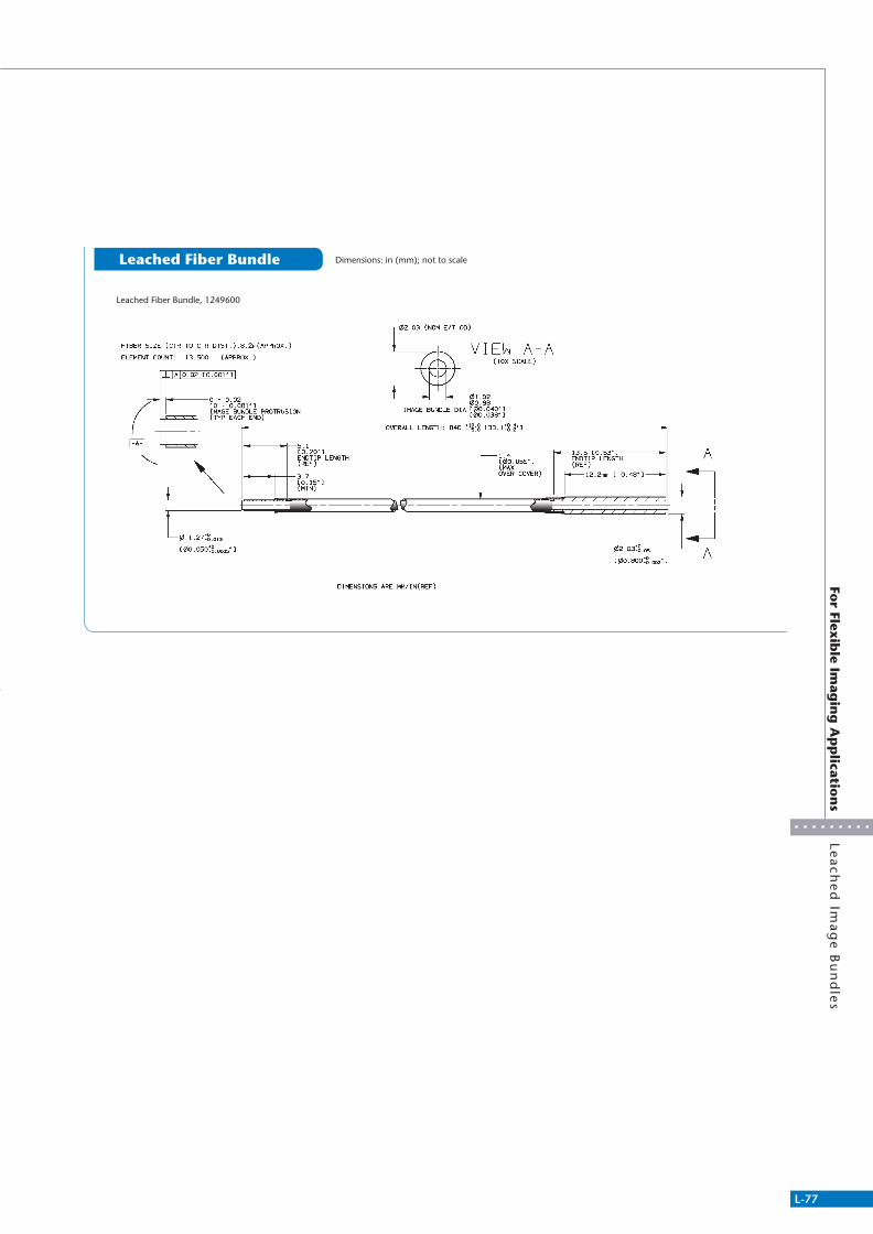
L-77
For Flex
ible Im
agin
g A
pp
lication
sLe
ach
ed
Ima
ge
Bu
nd
les
Leached Fiber Bundle Dimensions: in (mm); not to scale
Leached Fiber Bundle, 1249600
311766_MV_LensKatalog.indd 77 07.09.11 15:03
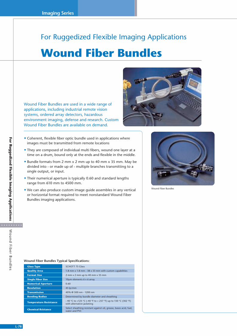
L-78
Imaging Series
Wo
un
d Fib
er B
un
dle
sFo
r Ru
gg
edized
Flexib
le Imag
ing
Ap
plicatio
ns
For Ruggedized Flexible Imaging Applications
Wound Fiber Bundles
• Coherent, flexible fiber optic bundle used in applications where images must be transmitted from remote locations
• They are composed of individual multi fibers, wound one layer at a time on a drum, bound only at the ends and flexible in the middle.
• Bundle formats from 2 mm x 2 mm up to 40 mm x 35 mm. May be divided into - or made up of - multiple branches transmitting to a single output, or input.
• Their numerical aperture is typically 0.60 and standard lengths range from 610 mm to 4500 mm.
• We can also produce custom image guide assembles in any vertical or horizontal format required to meet nonstandard Wound Fiber Bundles imaging applications.
Wound Fiber Bundles are used in a wide range of applications, including industrial remote vision systems, ordered array detectors, hazardous environment imaging, defense and research. Custom Wound Fiber Bundles are available on demand.
Wound Fiber Bundles
Wound Fiber Bundles Typical Specifications:
Glass Type SCHOTT 75 Glass
Quality Area 1.8 mm x 1.8 mm - 38 x 33 mm with custom capabilities
Format Size 2 mm x 2 mm up to 40 mm x 35 mm
Single Fiber Size 10μm elements 6 x 6 array
Numerical Aperture 0.60
Resolution 45 lp/mm
Transmission 40% @ 500 nm - 1200 nm
Bending Radius Determined by bundle diameter and sheathing
Temperature Resistance- 40 °C to +125 °C (-40 °F to + 257 °F) up to 150 °C (302 °F) with alternative jacketing
Chemical RsistanceSelect sheathing resistant against oil, grease, bases acid, fuel, water and PVC
311766_MV_LensKatalog.indd 78 07.09.11 15:03
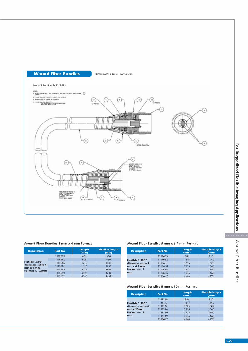
L-79
For R
ug
ged
ized Flex
ible Im
agin
g A
pp
lication
sW
ou
nd
Fibe
r Bu
nd
les
Wound Fiber Bundles Dimensions: in (mm); not to scale
Wound Fiber Bundles 4 mm x 4 mm Format
Description Part No.Length(mm)
Flexible length (mm)
Flexible .500” diameter cable 4 mm x 4 mm Format +/- .2mm
1119691 606 5301119690 906 8301119689 1216 11401119688 1826 17501119687 2756 26801119693 3806 37301119692 4566 4490
Wound Fiber Bundles 5 mm x 6.7 mm Format
Description Part No.Length(mm)
Flexible length (mm)
Flexible 1.300” diameter calbe 5 mm x 6.7 mm Format +/- .2 mm
1119683 886 8101119682 1116 10401119681 1796 17201119680 2716 26401119686 3776 37001119685 4536 44601119692 4566 4490
Wound Fiber Bundles 8 mm x 10 mm Format
Description Part No.Length(mm)
Flexible length (mm)
Flexible 1.300” diameter calbe 8 mm x 10mm Format +/- .2 mm
1119148 886 8101119147 1216 11401119145 1796 17201119144 2716 26401119150 3776 37001119149 4536 44601119692 4566 4490
WoundFiber Bundle 1119683
311766_MV_LensKatalog.indd 79 07.09.11 15:03

L-80
Explanation of Model Code
Explan
ation
of M
od
el Co
de
MML
D Coaxial IlluminationType
None
C Mount
M15.5×0.5
VI
CMMML-ST
MML
STMML-HRHR
Magnification Series WD Illumination
S Short Barrel Model
None
Exists
None
Mounted Parts Variable Aperture
Explanation of Model Code
Explanation of Model Code
311766_MV_LensKatalog.indd 80 07.09.11 15:03
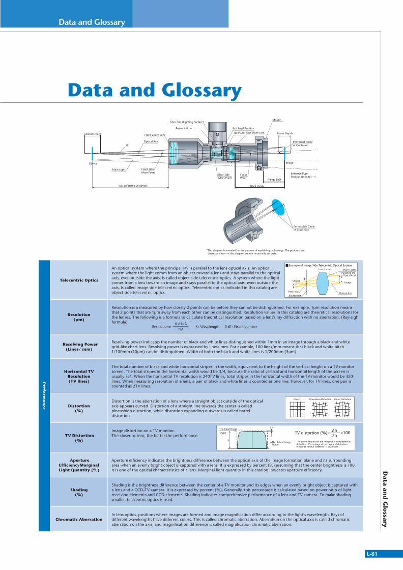
L-81
Data and GlossaryD
ata and
Glo
ssary
Data and Glossary
Entrance Pupil Position (Infinite)
Object Image
* This diagram is intended for the purpose of explaining technology. The positions and distances shown in this diagram are not necessarily accurate.
Focus Depth
Permitted Circle of Confusion
Focus Point
Field of Depth
uOptical Axis
Main Light Front Side Main Point
Front Zoom Lens
Fiber End (Lighting Surface)
Beam Splitter
Rear Side Main Point
Exit Pupil Position
Aperture
Back Focus
Flange Back
WD (Working Distance)
Permissible Circleof Confusion
Rear Zoom Lens
Mount
Perfo
rman
ce
Telecentric Optics
An optical system where the principal ray is parallel to the lens optical axis. An optical system where the light comes from an object toward a lens and stays parallel to the optical axis, even outside the axis, is called object side telecentric optics. A system where the light comes from a lens toward an image and stays parallel to the optical axis, even outside the axis, is called image side telecentric optics. Telecentric optics indicated in this catalog are object side telecentric optics.
Resolution(µm)
Resolution is a measured by how closely 2 points can be before they cannot be distinguished. For example, 1μm resolution means that 2 points that are 1μm away from each other can be distinguished. Resolution values in this catalog are theoretical resolutions for the lenses. The following is a formula to calculate theoretical resolution based on a lens's ray diffraction with no aberration. (Rayleigh formula)
Resolving Power (Lines/ mm)
Resolving power indicates the number of black and white lines distinguished within 1mm in an image through a black and white grid-like chart lens. Resolving power is expressed by lines/ mm. For example, 100 lines/mm means that black and white pitch 1/100mm (10μm) can be distinguished. Width of both the black and white lines is 1/200mm (5μm).
Horizontal TV Resolution(TV lines)
The total number of black and white horizontal stripes in the width, equivalent to the height of the vertical height on a TV monitor screen. The total stripes in the horizontal width would be 3/4, because the ratio of vertical and horizontal length of the screen is usually 3:4. When the horizontal TV resolution is 240TV lines, total stripes in the horizontal width of the TV monitor would be 320 lines. When measuring resolution of a lens, a pair of black and white lines is counted as one line. However, for TV lines, one pair is counted as 2TV lines.
Distortion(%)
Distortion is the aberration of a lens where a straight object outside of the optical axis appears curved. Distortion of a straight line towards the center is called pincushion distortion, while distortion expanding outwards is called barrel distortion
TV Distortion (%)
Image distortion on a TV monitor. The closer to zero, the better the performance.
Aperture EfficiencyMarginal Light Quantity (%)
Aperture efficiency indicates the brightness difference between the optical axis of the image formation plane and its surrounding area when an evenly bright object is captured with a lens. It is expressed by percent (%) assuming that the center brightness is 100. It is one of the optical characteristics of a lens. Marginal light quantity in this catalog indicates aperture efficiency.
Shading(%)
Shading is the brightness difference between the center of a TV monitor and its edges when an evenly bright object is captured with a lens and a CCD-TV camera. It is expressed by percent (%). Generally, this percentage is calculated based on power ratio of light receiving elements and CCD elements. Shading indicates comprehensive performance of a lens and TV camera. To make shading smaller, telecentric optics is used.
Chromatic AberrationIn lens optics, positions where images are formed and image magnification differ according to the light’s wavelength. Rays of different wavelengths have different colors. This is called chromatic aberration. Aberration on the optical axis is called chromatic aberration on the axis, and magnification difference is called magnification chromatic aberration.
AAObject
Iris Aperture
Front Focus
Lens/Lenses
B
FB
Main Light(Parallel to the
Optical Axis)
Optical Axis
Image
Example of Image Side Telecentric Optical System
Object Pincushion Distortion Barrel Distortion
Resolution=0.61×
NA: Wavelength 0.61: Fixed Number
h
The Actual Image Shape
h
The Ideal Image
Shape TV distortion (%)=
The curve amount on the long side is considered as distortion. Percentage of the depth of distortion �h against vertical screen is TV distortion
2hh ×100
311766_MV_LensKatalog.indd 81 07.09.11 15:03

L-82
Data and Glossary
Data an
d G
lossary
Dista
nce
WD(Working Distance)
(mm)Distance from the front end of a lens system to the object under inspection.
Focal Distance f (mm)
Back Focus / Front Focus
Focal distance is the distance from the optical system's principle point to the focal point. Distance from the vertex of the last lens to the back focal point is called back focus. Distance from the vertex of the first lens to the front focal point is called front focus.
Depth of Field
Depth is the distance between the nearest and farthest points that appear in acceptably sharp focus when an object is shifted back and forth from the best focal point. Depth range of the object side is called depth of field.
Depth of Field = 2 (Permissible Circle of Confusion x Effective F No Magnification2)
Images through lenses theoretically form as points. Acceptable blur on an acceptably clear image is called the permissible circle of confusion
Depth of FocusDepth is the distance between the nearest and farthest points that appear in acceptably sharp focus when a CCD is shifted back and forth from the best focal point. Depth range of the image side is called depth of focus.
Flange Back (mm)
Distance from the front of the camera mount plane to the image.
C-Mount Specifications
Brig
htn
ess
Numerical Aperture NA, NA'
When the half angle that an object makes on the entrance pupil is u, and refractive index is n, n x sin u is called object side numerical aperture, NA.When the half angle that an image makes on exit pupil is u', and refractive index is n', n' x sin u' is called image side numerical aperture, NA'.NAs in this catalog indicate object side numerical apertures. Numerical aperture is an important value that expresses lens resolution and brightness.
NA=n x sin u NA'=n’ x sin u’
The higher the NA, the greater the resolution and brightness are of the lens.
F Number F No
The value indicates lens brightness. It is calculated by dividing the focal distance of the lens by its effective diameter (entrance pupil diameter D mm) looking from its object side. It can also be calculated by NA and the lens' optical magnification ( ). The smaller the number the brighter the lens is.
F No=f/D
Effective F No
The value indicates lens brightness when an object is located in finite distance, the value which indicates the brightness when actually operated. The higher the optical magnification ( ), the darker the lens is.
Effective F No= /(2 x NA)=1/(2 x NA')Effective F No= (1+ ) x F No* *Approximation for Thin-Walled Systems
Mag
nifi
catio
n
Optical Magnification
Image size ratio against the object size.
=y’/y =b/a=NA/NA’=CCD Camera Element Size / Actual Size of Dield of View
Electronic Magnification
Electronic magnification is the magnification of an image on a CCD camera when it is displayed on a monitor screen.
Monitor Magnification
Monitor magnification is the magnification of an object displayed on a monitor screen through a lens.
Monitor Magnification = (Optical Magnification ) x (Electronic Magnification)
(Calculation Example) Optical Magnification = 0.2x, CCD Size 1/2" (Diagonal Line 8mm), Monitor 14" : Electronic Magnification =14 x 25.4 8 = 44.45 (Times)Monitor Magnification = 0.2 x 44.45= 8.89 (Times) (1 Inch = 25.4mm)
Field of View
Field of view is the size of an object that can be shot when the lens is attached to a CCD-TV camera.The size of field of view is (CCD format size) ÷ (optical magnification ).
(Calculation Example) Optical Magnification =0.2x, CCD Size 1/2" (4.8mm Long, 6.4mm Wide) :Size of Field of View Length =4.8/0.2=24 (mm)
Width =6.4/0.2=32 (mm)
Name Standard External Diameter No. of Screw Threads (for 25.4mm) Flange Back
U1 25.400mm 32 Threads 17.526mm
Object Imagey
y’
H H'
a b
311766_MV_LensKatalog.indd 82 07.09.11 15:03
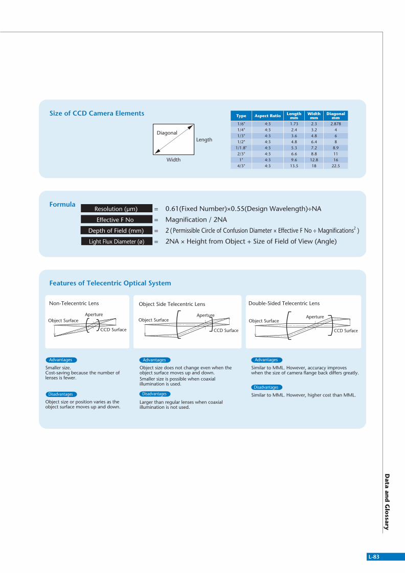
L-83
Data an
d G
lossary
Double-Sided Telecentric Lens
CCD Surface
Object SurfaceAperture
Object Side Telecentric Lens
Object SurfaceAperture
CCD Surface
Non-Telecentric Lens
Object SurfaceAperture
CCD Surface
Features of Telecentric Optical System
Formula0.61(Fixed Number)×0.55(Design Wavelength)÷NA
Magnification / 2NA
2 (Permissible Circle of Confusion Diameter × Effective F No ÷ Magnifications2 )
2NA × Height from Object + Size of Field of View (Angle)
=
=
=
=
Resolution (µm)
Effective F No
Depth of Field (mm)
Light Flux Diameter (ø)
Object size does not change even when the object surface moves up and down.Smaller size is possible when coaxial illumination is used.
Larger than regular lenses when coaxial illumination is not used.
Smaller size.Cost-saving because the number of lenses is fewer.
Object size or position varies as the object surface moves up and down.
Advantages
Disadvantages
Advantages
Disadvantages
Advantages
Disadvantages
Similar to MML. However, accuracy improves when the size of camera flange back differs greatly.
Similar to MML. However, higher cost than MML.
Size of CCD Camera Elements Type Aspect Ratio Length mm
Width mm
Diagonal mm
1/6" 4:3 1.73 2.3 2.8781/4" 4:3 2.4 3.2 41/3" 4:3 3.6 4.8 61/2" 4:3 4.8 6.4 8
1/1.8" 4:3 5.3 7.2 8.9 2/3" 4:3 6.6 8.8 111" 4:3 9.6 12.8 16
4/3" 4:3 13.5 18 22.5
Diagonal
Width
Length
311766_MV_LensKatalog.indd 83 07.09.11 15:03
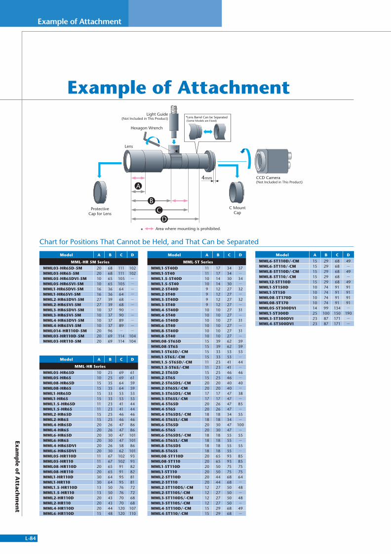
L-84
Example of Attachment
Exam
ple o
f Attach
men
t
Model A B C D
MML-HR 5M Series
MML03-HR65D-5M 20 68 111 102MML03-HR65-5M 20 68 111 102MML05-HR65DVI-5M 10 65 105 -
MML05-HR65VI-5M 10 65 105 -
MML1-HR65DVI-5M 16 36 64 -
MML1-HR65VI-5M 16 36 64 -
MML2-HR65DVI-5M 27 39 68 -
MML2-HR65VI-5M 27 39 68 -
MML3-HR65DVI-5M 10 37 90 -
MML3-HR65VI-5M 10 37 90 -
MML4-HR65DVI-5M 10 37 89 -
MML4-HR65VI-5M 10 37 89 -
MML014-HR110D-5M 20 96 - -
MML03-HR110D-5M 20 69 114 104MML03-HR110-5M 20 69 114 104
Model A B C D
MML-HR Series
MML05-HR65D 10 25 69 61MML05-HR65 10 25 69 61MML08-HR65D 15 35 64 59MML08-HR65 15 35 64 59MML1-HR65D 15 33 53 53MML1-HR65 15 33 53 53MML1.5-HR65D 11 23 41 44MML1.5-HR65 11 23 41 44MML2-HR65D 15 25 46 46MML2-HR65 15 25 46 46MML4-HR65D 20 26 47 86MML4-HR65 20 26 47 86MML6-HR65D 20 30 47 101MML6-HR65 20 30 47 101MML4-HR65DVI 20 26 58 86MML6-HR65DVI 20 30 62 101MML05-HR110D 11 67 102 93MML05-HR110 11 67 102 93MML08-HR110D 20 65 91 82MML08-HR110 20 65 91 82MML1-HR110D 30 64 95 81MML1-HR110 30 64 95 81MML1.5-HR110D 13 50 76 72MML1.5-HR110 13 50 76 72MML2-HR110D 20 43 70 68MML2-HR110 20 43 70 68MML4-HR110D 20 44 120 107MML6-HR110D 15 48 120 110
Model A B C D
MML-ST Series
MML1-ST40D 11 17 34 37MML1-ST40 11 17 34 -
MML1.5-ST40D 10 14 30 34MML1.5-ST40 10 14 30 -
MML2-ST40D 9 12 27 32MML2-ST40 9 12 27 -
MML3-ST40D 9 12 27 32MML3-ST40 9 12 27 -
MML4-ST40D 10 10 27 31MML4-ST40 10 10 27 -
MML6-ST40D 10 10 27 31MML6-ST40 10 10 27 -
MML8-ST40D 10 10 27 31MML8-ST40 10 10 27 -
MML08-ST65D 15 39 62 59MML08-ST65 15 39 62 59MML1-ST65D/-CM 15 33 53 53MML1-ST65/-CM 15 33 53 -
MML1.5-ST65D/-CM 11 23 41 44MML1.5-ST65/-CM 11 23 41 -
MML2-ST65D 15 25 46 46MML2-ST65 15 25 46 -
MML2-ST65DS/-CM 20 20 40 40MML2-ST65S/-CM 20 20 40 -
MML3-ST65DS/-CM 17 17 47 38MML3-ST65S/-CM 17 17 47 -
MML4-ST65D 20 26 47 85MML4-ST65 20 26 47 -
MML4-ST65DS/-CM 18 18 34 55MML4-ST65S/-CM 18 18 34 -
MML6-ST65D 20 30 47 100MML6-ST65 20 30 47 -
MML6-ST65DS/-CM 18 18 55 55MML6-ST65S/-CM 18 18 55 -
MML8-ST65DS 18 18 55 55MML8-ST65S 18 18 55 -
MML08-ST110D 20 65 93 85MML08-ST110 20 65 93 85MML1-ST110D 20 50 75 75MML1-ST110 20 50 75 75MML2-ST110D 20 44 68 64MML2-ST110 20 44 68 -
MML2-ST110DS/-CM 12 27 50 48MML2-ST110S/-CM 12 27 50 -
MML3-ST110DS/-CM 12 27 50 48MML3-ST110S/-CM 12 27 50 -
MML4-ST110D/-CM 15 29 68 49MML4-ST110/-CM 15 29 68 -
Model A B C D
MML6-ST110D/-CM 15 29 68 49MML6-ST110/-CM 15 29 68 -
MML8-ST110D/-CM 15 29 68 49MML8-ST110/-CM 15 29 68 -
MML12-ST110D 15 29 68 49MML1-ST150D 10 74 91 91MML1-ST150 10 74 91 91MML08-ST170D 10 74 91 91MML08-ST170 10 74 91 91MML05-ST300DVI 14 99 134 -
MML1-ST300D 25 100 150 190MML3-ST300DVI 23 87 171 -
MML4-ST300DVI 23 87 171 -
Example of Attachment*Lens Barrel Can be Separated (Some Models are Fixed)
* Area where mounting is prohibited.
Hexagon Wrench
ProtectiveCap for Lens
C MountCap
Lens
Light Guide(Not Included in This Product)
CCD Camera(Not Included in This Product)
4mm
A
BC
D
Chart for Positions That Cannot be Held, and That Can be Separated
311766_MV_LensKatalog.indd 84 07.09.11 15:03

L-85
Chart for Field of ViewC
hart fo
r Field o
f View
Chart for Field of View
MagnificationSensor Size
2/3" 1/1.8" 1/2" 1/3"Length Wides Angle Length Wides Angle Length Wides Angle Length Wides Angle
0.1x 66.00 88.00 110.00 53.19 71.76 89.32 48.00 64.00 80.00 36.00 48.00 60.000.14x 47.14 62.86 78.57 37.99 51.26 63.80 34.29 45.71 57.14 25.71 34.29 42.860.16x 41.25 55.00 68.75 33.24 44.85 55.83 30.00 40.00 50.00 22.50 30.00 37.500.18x 36.67 48.89 61.11 29.55 39.87 49.62 26.67 35.56 44.44 20.00 26.67 33.330.2x 33.00 44.00 55.00 26.60 35.88 44.66 24.00 32.00 40.00 18.00 24.00 30.000.3x 22.00 29.33 36.67 17.73 23.92 29.77 16.00 21.33 26.67 12.00 16.00 20.000.4x 16.50 22.00 27.50 13.30 17.94 22.33 12.00 16.00 20.00 9.00 12.00 15.000.5x 13.20 17.60 22.00 10.64 14.35 17.86 9.60 12.80 16.00 7.20 9.60 12.000.6x 11.00 14.67 18.33 8.87 11.96 14.89 8.00 10.67 13.33 6.00 8.00 10.000.7x 9.43 12.57 15.71 7.60 10.25 12.76 6.86 9.14 11.43 5.14 6.86 8.57
0.75x 8.80 11.73 14.67 7.09 9.57 11.91 6.40 8.53 10.67 4.80 6.40 8.000.8x 8.25 11.00 13.75 6.65 8.97 11.17 6.00 8.00 10.00 4.50 6.00 7.500.9x 7.33 9.78 12.22 5.91 7.97 9.92 5.33 7.11 8.89 4.00 5.33 6.671x 6.60 8.80 11.00 5.32 7.18 8.93 4.80 6.40 8.00 3.60 4.80 6.00
1.5x 4.40 5.87 7.33 3.55 4.78 5.95 3.20 4.27 5.33 2.40 3.20 4.002x 3.30 4.40 5.50 2.66 3.59 4.47 2.40 3.20 4.00 1.80 2.40 3.00
2.5x 2.64 3.52 4.40 2.13 2.87 3.57 1.92 2.56 3.20 1.44 1.92 2.403x 2.20 2.93 3.67 1.77 2.39 2.98 1.60 2.13 2.67 1.20 1.60 2.00
3.5x 1.89 2.51 3.14 1.52 2.05 2.55 1.37 1.83 2.29 1.03 1.37 1.714x 1.65 2.20 2.75 1.33 1.79 2.23 1.20 1.60 2.00 0.90 1.20 1.50
4.5x 1.47 1.96 2.44 1.18 1.59 1.98 1.07 1.42 1.78 0.80 1.07 1.335x 1.32 1.76 2.20 1.06 1.44 1.79 0.96 1.28 1.60 0.72 0.96 1.206x 1.10 1.47 1.83 0.89 1.20 1.49 0.80 1.07 1.33 0.60 0.80 1.007x 0.94 1.26 1.57 0.76 1.03 1.28 0.69 0.91 1.14 0.51 0.69 0.868x 0.83 1.10 1.38 0.66 0.90 1.12 0.60 0.80 1.00 0.45 0.60 0.759x 0.73 0.98 1.22 0.59 0.80 0.99 0.53 0.71 0.89 0.40 0.53 0.67
10x 0.66 0.88 1.10 0.53 0.72 0.89 0.48 0.64 0.80 0.36 0.48 0.6011x 0.60 0.80 1.00 0.48 0.65 0.81 0.44 0.58 0.73 0.33 0.44 0.5512x 0.55 0.73 0.92 0.44 0.60 0.74 0.40 0.53 0.67 0.30 0.40 0.5015x 0.44 0.59 0.73 0.35 0.48 0.60 0.32 0.43 0.53 0.24 0.32 0.4020x 0.33 0.44 0.55 0.27 0.36 0.45 0.24 0.32 0.40 0.18 0.24 0.30
311766_MV_LensKatalog.indd 85 07.09.11 15:03
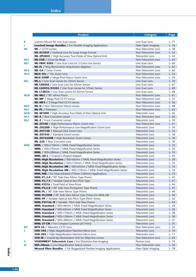
L-86
Index
Ind
ex
Product Category Page
B Camera Mount for Line Scan Lenses Line Scan Lens L- 71L Leached Image Bundles / For Flexible Imaging Applications Fiber Optic Imaging L- 76ML ML / CCTV Lenses Non-Telecentric Lens L- 58
ML-0310VF / Varifocal Lens for Large Image Format Non-Telecentric Lens L- 52ML-2PLBOX / High Accuracy Two Fields of View Optical Unit Telecentric Lens L- 44
MLE ML-EXR / Close-Up Rings Non-Telecentric Lens L- 62MLF ML-F80C-0205 / Line Scan Lens for 3 Color Line Sensor Line Scan Lens L- 66
ML-FL / Ring Illumination Attachment Adapters Non-Telecentric Lens L- 62MLG ML-GA / Grass Covers Non-Telecentric Lens L- 62MLH MLH-10x / 10x Zoom Lens Non-Telecentric Lens L- 54
MLH-3XMP / Mega Pixel Macro Zoom Lens Non-Telecentric Lens L- 54MLL ML-L / Line Scan Lenses for 35mm Sensor Line Scan Lens L- 70
ML-L00502 / Line Scan Lens for 62mm Sensor Line Scan Lens L- 67ML-L02035/03505 / Line Scan Lenses for 57mm Sensor Line Scan Lens L- 69ML-L12K5A / Line Scan Lenses for 62mm Sensor Line Scan Lens L- 68
MLM ML-MLC / 90˚ Mirror Prism Non-Telecentric Lens L- 61ML-MP / Mega Pixel CCTV Lenses Non-Telecentric Lens L- 57ML-MP3 / 3 Mega Pixel CCTV Lenses Non-Telecentric Lens L- 56
MLN ML-N / Non-Telecentric Macro Lenses Non-Telecentric Lens L- 48MLP ML-PL / Polarizers Non-Telecentric Lens L- 62MLW ML-W1000 / High Accuracy Two Fields of View Optical Unit Telecentric Lens L- 45MLX ML-X / Rear Converter Lenses Non-Telecentric Lens L- 60MLZ ML-Z / Front Converter Lenses Telecentric Lens L- 39
ML-Z0108 / High Performance Macro Zoom Lens Non-Telecentric Lens L- 51ML-Z0220D / High-Performance Low Magnification Zoom Lens Telecentric Lens L- 34ML-Z0315D / Manual Click Zoom Lens Telecentric Lens L- 35ML-Z07545 / Standard Zoom Lenses Telecentric Lens L- 38ML-Z07545HR / High Resolution Zoom Lenses Telecentric Lens L- 36ML-Z2X / Rear Converter Lens Telecentric Lens L- 39
MML MML / WD=110mm / MML Fixed Magnification Series Telecentric Lens L- 32MML / WD=195mm / MML Fixed Magnification Series Telecentric Lens L- 32MML / WD=200mm / MML Fixed Magnification Series Telecentric Lens L- 33MML-AD-L / Coaxial L-Shaped Adapter Telecentric Lens L- 45MML-High Resolution / WD=65mm / MML Fixed Magnification Series Telecentric Lens L- 20MML-High Resolution / WD=110mm / MML Fixed Magnification Series Telecentric Lens L- 23MML-High Resolution 5M / WD=65mm / MML Fixed Magnification Series Telecentric Lens L- 16MML-High Resolution 5M / WD=110mm / MML Fixed Magnification Series Telecentric Lens L- 16MML-NIR / For Near-Infrared (770nm-1200nm) Applications Telecentric Lens L- 33MML-P1,3,4 / 90˚ Side View Mirror Type Prisms Telecentric Lens L- 41MML-P2,7,9 / Variable Optical Axis Pitch Type Telecentric Lens L- 41MML-P2S16 / Dual Field of View Prism Telecentric Lens L- 44MML-P5,6,8 / 90˚ Side View Pentaprism Type Prisms Telecentric Lens L- 41MML-PL / 90˚ Side View Mirror Type Prisms Telecentric Lens L- 40MML-PL25HR / 90˚ Side View Mirror Type Prisms for MML-HR Telecentric Lens L- 40MML-PP / Variable Optical Axis Pitch Type (Pitch 3mm) Telecentric Lens L- 42MML-PSV16L/R / Variable Pitch Side View Prisms Telecentric Lens L- 43MML-Standard / WD=40mm / MML Fixed Magnification Series Telecentric Lens L- 24MML-Standard / WD=65mm / MML Fixed Magnification Series Telecentric Lens L- 26MML-Standard / WD=110mm / MML Fixed Magnification Series Telecentric Lens L- 28MML-Standard / WD=150mm / MML Fixed Magnification Series Telecentric Lens L- 30MML-Standard / WD=300mm / MML Fixed Magnification Series Telecentric Lens L- 31MML-ST-CM / For Compact Cameras (ø17mm) Telecentric Lens L- 31
MT MTE-55 / Telecetric CCTV Lens Non-Telecentric Lens L- 55S SOD-10X / High Magnification Machine Micro Lens Telecentric Lens L- 10
SOD-20X / High Magnification Machine Micro Lens Telecentric Lens L- 11SOD-III / Coaxial Epi-illumination Unit for Objective Lenses Non-Telecentric Lens L- 63
V VISIONMES® Telecentric Lens / For Distortion-free Imaging Partner Lens L- 74W WD=90mm / Low Magnification Macro Lenses Non-Telecentric Lens L- 50
Wound Fiber Bundles / For Ruggedized Flexible Imaging Applications Fiber Optic Imaging L- 78
311766_MV_LensKatalog.indd 86 07.09.11 15:03

Introduction
Machine Vision Systems combine lighting, imaging, and data
processing to inspect, monitor, and control industrial production
processes. They have been employed in a variety of industries on
a multitude of applications.
As experts in providing Lighting and Imaging solutions for
today’s vast machine vision market, MORITEX and SCHOTT
offer standard and customized solutions for illumination, lens
design, and front end optical systems.
With decades of experience, and extensive know-how, MORITEX
and SCHOTT can provide the total machine vision illumination
and imaging solution designed exclusively for you comprised
from our vast product portfolio.
MORITEX and SCHOTT are leading global suppliers of
illumination and imaging components for machine vision
applications. Our unparalleled expertise in these areas makes
us uniquely qualified to service all different levels from system
design to integrated lighting and imaging system solutions.
�Please review the products featured in this catalog and let us
know how we can best serve you!
Unparalleled Expertise
L-2 L-87
Dimensions and specifications in this catalog may vary. Before purchasing,please check the delivery specifications or diagrams.
*Company and product names stated in this catalog are trademarks or registered trademarks of their respective companies.*Product specifications, design, values, etc. may vary.*The contents in this catalog are for the present as of October 2011.

Machine VisionGeneral Catalog
MV
2011
.10
MV
-L-E
520
0 P
rint
ed in
Ger
man
y
Lens
Asia
MORITEX CorporationSunny Building Ikebukuro4-39-11 Higashi Ikebukuro,Toshima-ku, Tokyo, 170-0013JapanTel : +81-3-6367-3634Fax: +81-3-3590-6627E-mail : [email protected] www.moritex.co.jp
MORITEX Asia Co., Ltd.Units 1201A and 1211 - 1212 of Tower 1 of Ever Gain Plaza, 88 Container Port Road, Kwai Chung, New Territories, Hong KongTel : +852-2439-0968 Fax: +852-2439-0377E-mail : [email protected]
MORITEX Singapore Pte Ltd. Blk 211 Woodlands Avenue 9 #04-84Woodlands Spectrum II, Singapore 738960Tel : +65-6515-9368Fax: +65-6515-9360E-mail : [email protected] Lighting and ImagingSCHOTT ShanghaiUnit 301, Innov Tower, No.1801 Hongmei Road,Shanghai, PRC (200233)Tel : +86(0)21 33678000 - 170Fax: +86(0)21 33678080E-mail : [email protected]/china
Lighting and ImagingSCHOTT TAIWAN Ltd.8F-3, No. 126, Sec.4Nanking E. Road,Taipei 105, TaiwanTel : +886(2) 2570-9626Fax: +886(2) 2570-9628 E-mail : [email protected]/taiwan
Europe
Lighting and ImagingSCHOTT AGOtto Schott Strasse 2, 55127 Mainz GermanyTel : +49(0)6131/66-7752Fax: +49(0)6131/66-7850E-mail : [email protected]/lightingimaging
Lighting and ImagingSCHOTT Benelux B.V.Randweg 3A, 4104 AC Culemborg NetherlandsTel : +31(0)344-670911Fax: +31(0)344-621802E-mail : [email protected]/lightingimaging Lighting and ImagingSCHOTT France SAS6 bis, rue Fournier, FR-Clichy, FranceTel : +33(0)14087-3900Fax: +33(0)14270-7322E-mail : [email protected]/lightingimaging Lighting and ImagingSCHOTT UK Ltd.122 Drummond Road, ST16 3EL Stafford, Great BritainTel : +44(0)1785-223166Fax: +44(0)1785-223522E-mail : [email protected]/lightingimaging
Lighting and ImagingSCHOTT Glas Export GmbHRasko Building, 40 Ha'atzmaut St., 56304 Yehud, IsraelTel : +972(0)353617-11Fax: +972(0)353617-10E-mail : [email protected]/lightingimaging
North America
Lighting and ImagingSCHOTT North America, Inc.6862 Santa Teresa Blvd.San Jose, CA 95119 U.S.A.Tel : +1-408-363-2100Fax: +1-408-363-9980E-mail : [email protected]/lightingimaging
Vol.001
MO
RIT
EX an
d SC
HO
TT
Machine V
ision General C
atalo gLens
Vo
l.001
2 rue René Laennec 51500 Taissy France Fax: 03 26 85 19 08, Tel : 03 26 82 49 29
E-mail:[email protected] web : www.hvssystem.com