
Murray Riding Lawn Mower Diagram -...
52
The owner must be certain that all the product information is included with the unit. This information includes the INSTRUCTION BOOKS, the REPLACEMENT PARTS and the WARRANTIES. This information must be included to make sure state laws and other laws are followed. PRODUCT INFORMATION Read and keep this book for future reference. This book contains important information on SAFETY, PREPARATION, OPERATION, AND MAINTENANCE. RECORD THE FOLLOWING INFORMATION ABOUT YOUR UNIT. THIS INFORMATION IS NECESSARY WHEN ORDERING PARTS OR IN CASE OF LOSS OR THEFT. F-040740L BUILT IN THE MODEL 425620x92B
Transcript of Murray Riding Lawn Mower Diagram -...
The owner must be certain that allthe product information is included with the unit.This information includesthe INSTRUCTION BOOKS,the REPLACEMENT PARTS and the WARRANTIES.This information must be included to make sure state laws and other lawsare followed.
PRODUCT INFORMATION
Read and keep this book for future reference. This book contains important information on SAFETY, PREPARATION, OPERATION, AND MAINTENANCE.
RECORD THE FOLLOWING INFORMATION ABOUT YOUR UNIT. THISINFORMATION IS NECESSARY WHEN ORDERING PARTS OR IN CASEOF LOSS OR THEFT.
F-040740L
BUILT IN THE
MODEL425620x92B

2F-040740L
TABLE OF CONTENTSWARRANTY 2. . . . . . . . . . . . . . . . . . . . . . . . . . . . . . . . . . . . . . RESPONSIBILITY OF THE OWNER 3. . . . . . . . . . . . . . . . . SAFETY RULES 3. . . . . . . . . . . . . . . . . . . . . . . . . . . . . . . . . . INTERNATIONAL PICTORIALS 9. . . . . . . . . . . . . . . . . . . . . ASSEMBLY 10. . . . . . . . . . . . . . . . . . . . . . . . . . . . . . . . . . . . . . .
PARTS BAG - CONTENTS 10. . . . . . . . . . . . . . . . . . . . . . . . . . . . . . HOW TO INSTALL THE SEAT 11. . . . . . . . . . . . . . . . . . . . . . . . . . . HOW TO ASSEMBLE THE STEERING WHEEL 11. . . . . . . . . . . . MAINTENANCE FREE BATTERY 12. . . . . . . . . . . . . . . . . . . . . . . . HOW TO INSTALL THE BATTERY CABLES 12. . . . . . . . . . . . . . IMPORTANT! BEFORE YOU START MOWING 13. . . . . . . . . . . . HOW TO PREPARE THE ENGINE 13. . . . . . . . . . . . . . . . . . . . . . . CHECK THE LEVEL OF THE MOWER HOUSING 13. . . . . . . . . . CHECK THE TIRES 13. . . . . . . . . . . . . . . . . . . . . . . . . . . . . . . . . . . .
OPERATION 14. . . . . . . . . . . . . . . . . . . . . . . . . . . . . . . . . . . . . . LOCATION OF CONTROLS 14. . . . . . . . . . . . . . . . . . . . . . . . . . . . . ATTACHMENTS 15. . . . . . . . . . . . . . . . . . . . . . . . . . . . . . . . . . . . . . . HOW TO USE THE THROTTLE CONTROL 15. . . . . . . . . . . . . . . . HOW TO USE THE BLADE ROTATION CONTROL 15. . . . . . . . . HOW TO USE THE SPEED CONTROL PEDAL 16. . . . . . . . . . . . HOW TO DISCONNECT THE TRANSMISSION 16. . . . . . . . . . . . HOW TO SET THE PARKING BRAKE 17. . . . . . . . . . . . . . . . . . . . HOW TO CHANGE THE CUTTING HEIGHT 17. . . . . . . . . . . . . . . HOW TO STOP THE UNIT 17. . . . . . . . . . . . . . . . . . . . . . . . . . . . . . HOW TO TRANSPORT THE UNIT 17. . . . . . . . . . . . . . . . . . . . . . . . HOW TO OPERATE WITH THE MOWER HOUSING 18. . . . . . . . HOW TO OPERATE THE UNIT ON HILLS 18. . . . . . . . . . . . . . . . . BEFORE STARTING THE ENGINE 19. . . . . . . . . . . . . . . . . . . . . . . HOW TO START THE ENGINE 19. . . . . . . . . . . . . . . . . . . . . . . . . . OPERATING TIPS 20. . . . . . . . . . . . . . . . . . . . . . . . . . . . . . . . . . . . . MOWING AND BAGGING TIPS 20. . . . . . . . . . . . . . . . . . . . . . . . . .
MAINTENANCE 21. . . . . . . . . . . . . . . . . . . . . . . . . . . . . . . . . . . MAINTENANCE CHART 21. . . . . . . . . . . . . . . . . . . . . . . . . . . . . . . . HOW TO CHECK THE MUFFLER 21. . . . . . . . . . . . . . . . . . . . . . . . HOW TO REMOVE AND INSTALL THE BLADE 22. . . . . . . . . . . HOW TO SHARPEN THE BLADE 22. . . . . . . . . . . . . . . . . . . . . . . . HOW TO ADJUST THE BLADE ROTATION CONTROL 23. . . . . HOW TO CHECK AND ADJUST THE MOTION DRIVE BELT 24HOW TO CHECK AND ADJUST THE DRIVE BRAKE 25. . . . . . . MAINTENANCE FREE BATTERY 25. . . . . . . . . . . . . . . . . . . . . . . . HOW TO CHARGE THE BATTERY 25. . . . . . . . . . . . . . . . . . . . . . . WHERE TO LUBRICATE 26. . . . . . . . . . . . . . . . . . . . . . . . . . . . . . . . HOW TO CHECK THE FUEL FILTER 26. . . . . . . . . . . . . . . . . . . . . CHECK THE TIRES 26. . . . . . . . . . . . . . . . . . . . . . . . . . . . . . . . . . . . HOW TO REMOVE THE MOWER HOUSING 27. . . . . . . . . . . . . . HOW TO INSTALL THE MOWER HOUSING 27. . . . . . . . . . . . . . . HOW TO ADJUST THE GAUGE WHEELS 28. . . . . . . . . . . . . . . . HOW TO LEVEL THE MOWER HOUSING 29. . . . . . . . . . . . . . . . HOW TO REPLACE THE MOTION DRIVE BELT 30. . . . . . . . . . . HOW TO REPLACE THE MOWER DRIVE BELT 31. . . . . . . . . . . HOW TO INSTALL THE WHEELS 32. . . . . . . . . . . . . . . . . . . . . . . . HOW TO REPLACE THE FUSE 33. . . . . . . . . . . . . . . . . . . . . . . . . . HOW TO REPLACE THE LIGHT BULB 33. . . . . . . . . . . . . . . . . . . HOW TO CLEAN THE MOWER HOUSING 33. . . . . . . . . . . . . . . . STORAGE (OVER 30 DAYS) 33. . . . . . . . . . . . . . . . . . . . . . . . . . . .
TROUBLE SHOOTING CHART 34. . . . . . . . . . . . . . . . . . . . . HOW TO ORDER REPAIR PARTS 35. . . . . . . . . . . . . . . . . . . PARTS LIST 36. . . . . . . . . . . . . . . . . . . . . . . . . . . . . . . . . . . . . . SLOPE GUIDE 50. . . . . . . . . . . . . . . . . . . . . . . . . . . . . . . . . . . . INDEX 51. . . . . . . . . . . . . . . . . . . . . . . . . . . . . . . . . . . . . . . . . . . LAWN TRACTOR ACCESSORIES 52. . . . . . . . . . . . . . . . . .
MURRAY, INC. Two Year Limited Warranty Murray, Inc. warrants to the original purchaser that this unit shall be free from defects in material and workmanship under normaluse and service for a period of Two (2) Years from the date of purchase; however, this warranty does not cover engines,accessories (such as snow blowers, snow blades, grass baggers and plows), transmissions, batteries and Normal Wear Parts(except as noted below) or transaxles as the companies that manufacture these items furnish their own warranties and provideservice through their authorized field service facilities. For additional information, see the warranties covering these particularparts. If you are uncertain whether your unit contains or is equipped with one or more of these parts, consult your dealer priorto purchase. Subject to the terms and conditions noted in this Limited Warranty, we shall, at our option, repair or replace at nocost to the original purchaser any part covered by this Limited Warranty during the applicable warranty period.In the event the battery proves defective within ninety (90) days from the date of purchase, we will replace it without charge. Ifthe battery proves defective after (90) days but within one hundred twenty (120) days from the date of purchase, we will replaceit for a charge of one half (1/2) of the retail price of the battery in effect at the time of return.Normal Wear Parts are defined as belts, blades, blade adapters, pneumatic tires, headlights and seat covers. These parts arewarranted to be free from defects in material and workmanship as delivered with the product. Any claim for repair or replacementof Normal Wear Parts must be made within thirty (30) days of the date of purchase. No claims involving damage caused frommaterial use, abuse or misuse will be honored.This Murray, Inc. Two (2) Year Limited Warranty is your exclusive remedy; however, this warranty is void or does not applyto any unit that has been tampered with, altered, misused, abused or used for rental or other commercial and/or professional(non-homeowner) uses. Your warranty does not cover minor mechanical adjustments which are not due to any defect in materialor workmanship. For assistance in making such adjustments, consult your Instruction Book.To make a claim under this Murray, Inc. Two (2) Year Limited Warranty, return the unit (or if authorized in advance, the defectivepart) along with your proof of purchase to an Authorized Service Center near you. To locate the nearest Authorized ServiceCenter, call the Central Parts Distributor for your area shown in the list provided with your unit or check the Yellow Page listingsin your local telephone directory. If you return the entire unit, we will repair the unit. If we authorize the return of the defectivepart only, we will either replace or repair the part. In the case of a defect in a transmission or differential (as distinguished froma transaxle), the entire transmission or differential must be returned since they do not include user serviceable parts.This Murray, Inc. Two (2) Year Limited Warranty gives you specific legal rights, and you may also have other rights which varyfrom state to state. This Limited Warranty is given in lieu of all other expressed and implied warranties including theimplied warranty of merchantability and warranty of fitness for a particular purpose. If you need additional informationon this written warranty or assistance in obtaining service, write or call: MURRAY, INC., Outdoor Power Equipment, CustomerService Department, P.O. Box 268, Brentwood, Tennessee 37027. (1-800-224-8940)

OWNER’S INFORMATION
3F-040740L
This instruction book is for several different models. The instructionsare written for a person with some mechanical ability. Like most ser-vice books, not all the steps are described. Steps on how to loosen ortighten fasteners are steps anyone can follow with some mechanicalability. Read and follow these instructions before you use the unit.Know your product: If you understand the unit and how the unit oper-ates, you will get the best performance. As you read this manual, com-pare the illustrations to the unit. Learn the location and the function ofthe controls. To help prevent an accident, follow the operating instruc-tions and the safety rules. Keep this manual for future reference.IMPORTANT: Many units are not assembled and are sold in car-tons. It is the responsibility of the owner to make sure the assemblyinstructions in this manual are exactly followed. Other units are pur-chased in an assembled condition. On assembled units, it is the re-sponsibility of the owner to make sure the unit is correctlyassembled. The owner must carefully check the unit according tothe instructions in this manual before it is first used.
Engine Exhaust, some of its constituents, andcertain vehicle components contain or emitchemicals known to the State of California tocause cancer and birth defects or other repro-ductive harm.
Battery posts, terminals and related accesso-ries contain lead and lead compounds, chemi-cals known to the State of California to causecancer and birth defects or other reproductiveharm. WASH HANDS AFTER HANDLING.
RESPONSIBILITY OF THE OWNERThe responsibility of the owner is to follow the instructions below.
1. Carefully read and follow the rules for safe operation.2. Follow all the assembly instructions.3. Inspect the unit.4. Make sure that the operator of the unit knows how to correctly
use all standard and accessory equipment.5. Operate the unit only with guards, shields, and other safety
items in place and working correctly.6. Correctly adjust the unit.7. Service the unit only with authorized or approved replacement
parts.8. Complete all maintenance on the unit.
Environmental Awareness
� Do not fill the engine’s fuel tank completely full.
� Drain fuel for off-season storage.
� Use only unleaded gasoline.
� Service the air cleaner regularly.
� Change oil regularly. Use 10W-30 oil in summer.
� Tune-up the engine regularly.
� Keep equipment in efficient operating condition.
� Dispose of used engine oil properly.
SAFETY RULESSafe Operation Practices for Ride-on Mowers
WARNING: This cutting machine is capable of amputating hands and feet and throwing objects. Failure to observe thefollowing safety instructions could result in serious injury or death.
I. General operation1. Read, understand and follow all instructions in the Instruction Book, on the machine, the engine and with any attachments before
starting.2. Only allow responsible adults, who are familiar with the instructions, to operate the machine.3. Clear the area of objects such as rocks, toys, wire, etc., which could be picked up and thrown by the blade.4. Be sure the area is clear of other people before mowing. Stop the machine if anyone enters the area.5. Never carry passengers.6. Turn off power to the blades or any attachments before backing up. Do not mow in reverse unless absolutely necessary. Always look
down and behind before and while backing.7. Be aware of the mower discharge direction and do not point it at anyone. Do not operate the mower without either the entire grass bagger
or the mower guard in place.8. Slow down before turning.9. Never leave a machine unattended with the engine running. Always turn off the blade(s), set the parking brake, stop the engine and
remove the key before dismounting.10. Turn off power to attachment(s) when transporting or not in use. Turn off the blade(s) when not mowing.11. Stop the engine before removing the grass bagger or unclogging the chute.12. Mow only in daylight or good artificial light.13. Do not operate the machine while under the influence of alcohol or drugs or when very tired.14. Watch for traffic when operating near or crossing roadways.15. Use extra caution when loading or unloading the machine into a trailer or truck.16. Turn off all attachment clutches before attempting to start the engine.17. Always wear goggles, safety glasses, or an eye shield when you operate the unit to protect your eyes from foreign objects that can be
thrown from the unit. Always wear eye protection when you make an adjustment or repair to the machine.18. Use care when pulling loads or using heavy equipment.
a. Use only approved drawbar hitch points.

OWNER’S INFORMATION
4F-040740L
b. Limit loads to those you can safely control.c. Do not turn sharply. Use care when backing.d. Use counterweights or wheel weights when suggested in the Instruction Book.
19. Do not operate this machine if you are taking drugs or other medication which can cause drowsiness or affect your ability to operatethis machine.
20. Do not use this machine if you are mentally or physically unable to operate this machine safely.21. Data indicates that operators, age 60 years and above, are involved in a large percentage of riding mower related injuries. These opera-
tors should evaluate their ability to operate a riding mower safely enough to protect themselves and others from serious injury.
II. Slope operationSlopes and rough terrain are major factors related to loss-of-control and tip-over accidents, which can result in severe injuryor death. ALL slopes require extra caution. If you cannot back up the slope or if you feel uneasy on the slope, do not mow it. Seethe “Slope Guide” in the back of this book to check for safe operation.
DO1. Mow up and down slopes, not across.2. Remove obstacles such as rocks, limbs, etc...3. Watch for holes, ruts or bumps. Uneven terrain could overturn the machine. Tall grass can hide obstacles.4. Use slow speed on slopes. Do not make sudden speed changes.5. Follow the manufacturer’s recommendations for wheel weights or counterweights to improve stability.6. Use extra care with grass baggers or other attachments, they can change the stability of the machine.7. Keep all movement on the slopes slow and gradual. Do not make sudden changes in speed or direction.8. Avoid starting or stopping on a slope. If tires lose traction, turn off the blades and proceed slowly straight down the slope.
DO NOT1. Do not turn on slopes unless absolutely necessary, then only turn slowly and gradually downhill, if possible.2. Do not mow drop-offs, ditches or embankments. A wheel over the edge or an edge caving in could cause a sudden overturn and an
injury or death.3. Do not mow on wet grass. Reduced traction could cause sliding.4. Do not try to stabilize the machine by putting your foot on the ground.5. Do not use a grass bagger or other rear mounted accessories on steep slopes (greater than 10 degrees).
III. ChildrenTragic accidents can occur if the operator is not alert to the presence of children. Children are often attracted to the machine andthe mowing activity. NEVER assume that children will remain where you last saw them.1. Keep children out of the mowing area and in the watchful care of another responsible adult.2. Be alert and turn the engine off if children enter the area.3. Before and when backing, look behind and down for small children.4. Never carry children or any passengers, even with the blades off. They may fall off and be seriously injured or interfere with the safe
operation of the machine.5. Never allow children to operate the machine. Instruct children in the potential dangers of the machine.6. Use extra care when approaching blind corners, shrubs, trees or other objects that may obscure vision.
IV. Service1. Use extra care when handling gasoline and other fuels. Fuels are flammable and the vapors are explosive.
a. Use only an approved container.b. Never remove the gas cap or add fuel with the engine running. Allow the engine to cool for several minutes before refueling. Do not smoke.c. Never refuel the machine indoors.d. Never store the machine with fuel in the tank or fuel container inside where there is an open flame, such as a water heater.
2. Never start or run the engine inside a closed area.3. Keep all nuts and bolts, especially the blade attachment nuts tight. Frequently check the blade(s) for wear or damage such as cracks
and nicks. A blade that is bent or damaged must be immediately replaced with an original equipment blade from an authorized servicedealer. For safety, replace the blade every two years. Keep the equipment in good condition.
4. Never tamper with the safety devices. Check their proper operation regularly.5. To reduce fire hazards, keep the machine free of grass, leaves or other debris build-up. Clean up oil or fuel spills. Allow the machine
to cool before storing.6. Stop and inspect the equipment if you strike an object. Repair, if necessary, before restarting.7. Never make adjustments or repairs with the engine running. The carburetor can be adjusted with the engine running. Do not change
the engine governor settings or over-speed the engine.8. Grass bagger components are subject to wear, damage and deterioration, which could expose moving parts or allow objects to be
thrown. For storage, always make sure the grass bag is empty. Frequently check components and replace with manufacturer’s recom-mended parts when necessary.
9. Mower blade(s) are sharp and can cut. Wrap the blade(s) or wear gloves and use extra caution when servicing them or the blade housingarea.
10. Check the brake operation frequently. Adjust and service as required.11. Wait for all movement to stop before servicing any part of the unit.
Look for this symbol to indicate important safetyprecautions. This symbol indicates: “Attention!Become Alert! Your Safety Is At Risk.”
SAFE MOWING GUIDE
5F-040740L
Each person that operates powerequipment must learn to use correct andsafe mowing procedures. To help youlearn, carefully read the followingpages. Most of the time the operator wasnot correctly shown or did not read theinstructions on the unit or in the InstructionBook before using the unit. Also, someoperators do not have enough experience.The result is unsafe use, endangering theoperator, bystanders and the equipment.Another result can be a poor appearanceof the area mowed.
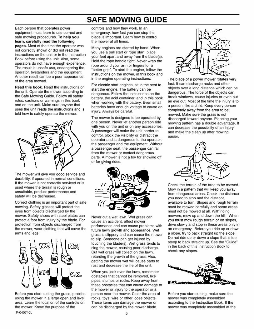
Read this book. Read the instructions onthe unit. Operate the mower according tothe Safe Mowing Guide. Follow all safetyrules, cautions or warnings in this bookand on the unit. Make sure anyone thatuses the unit reads the instructions and istold how to safely operate the mower.
The mower will give you good service anddurability, if operated in normal conditions.If the mower is not correctly serviced or isused where the terrain is rough orunsuitable, product performance andsafety will be decreased.
Correct clothing is an important part of safemowing. Safety glasses will protect theeyes from objects discharged by themower. Safety shoes with steel plates canprotect a foot from injury by the blade. Forprotection from objects discharged fromthe mower, wear clothing that will cover thearms and legs.
Before you start cutting the grass, practiceusing the mower in a large open and levelarea. Learn the location of the controls onthe mower. Know the purpose of the
controls and how they work. In anemergency, how fast you can stop theblade is important. Learn how to controlthe mower at all times.
Many engines are started by hand. Whenyou use a pull start or rope start, placeyour feet apart and away from the blade(s).Hold the rope handle tight. Never wrap therope around your arm or fingers for a“better grip”. To start the engine, follow theinstructions on the mower, in this book andin the engine operating instructions.
For electric start engines, sit in the seat tostart the engine. The battery can bedangerous. Follow the instructions on thebattery, the acid container, and in this bookwhen working with the battery. Even smallbatteries have enough voltage to cause aninjury. Always be careful.
The mower is designed to be operated byone person. Never let another person ridewith you on the unit or on any accessories.A passenger will make the unit harder tocontrol, block the visibility or distract theoperator and is dangerous to the operator,the passenger and the equipment. Withouta passenger seat, the passenger can fallfrom the mower or contact dangerousparts. A mower is not a toy for showing offor for giving rides.
Never cut a wet lawn. Wet grass cancause an accident, affect mowerperformance and can cause problems withfuture lawn growth and appearance. Wetgrass is slippery and can cause the mowerto slip. Someone can get injured bytouching the blade(s). Wet grass tends toclog the mower, causing poor discharge.Cut wet grass will collect on the lawn,retarding the growth of the grass. Also,getting the mower wet will cause parts torust and decrease the life of the unit.
When you look over the lawn, rememberobstacles that cannot be removed, likepipes, stumps or rocks. Keep away fromthese obstacles that can cause damage tothe mower or injury to the operator or aperson near the mower. Clear the area ofrocks, toys, wire or other loose objects.These items can damage the mower orcan be discharged by the mower blade.
The blade of a power mower rotates veryfast. It can discharge rocks and otherobjects over a long distance which can bedangerous. The force of the objects canbreak windows, cause injuries or even putan eye out. Most of the time the injury is toa person, like a child. Keep every personcompletely away from the area to bemowed. Make sure the grass is notdischarged toward anyone. Planning yourmowing pattern has a double advantage. Itcan decrease the possibility of an injuryand make the clean up after mowingeasier.
Check the terrain of the area to be mowed.Mow in a pattern that will keep you awayfrom dangerous areas. Check the distanceyou need to stop and the distanceavailable to turn. Slopes and rough terrainmust be mowed carefully and some areasmust not be mowed at all. With ridingmowers, mow up and down the hill. Whenyou must mow rough terrain or on slopes,drive slowly and stop in these areas only inan emergency. Before you ride up or downa slope, try to back straight up the slope.Do not ride up or down a slope that is toosteep to back straight up. See the “Guide”in the back of this Instruction Book tocheck any slopes.
Before you start cutting, make sure themower was completely assembledaccording to the Instruction Book. If themower was completely assembled at the
SAFE MOWING GUIDE
6F-040740L
store, you must still check the moweraccording to the assembly instructions.Make sure the mower is correctlyassembled and that all fasteners are tight.Make sure the engine has the correctamount of oil. Check these items oftenduring the life of the mower.
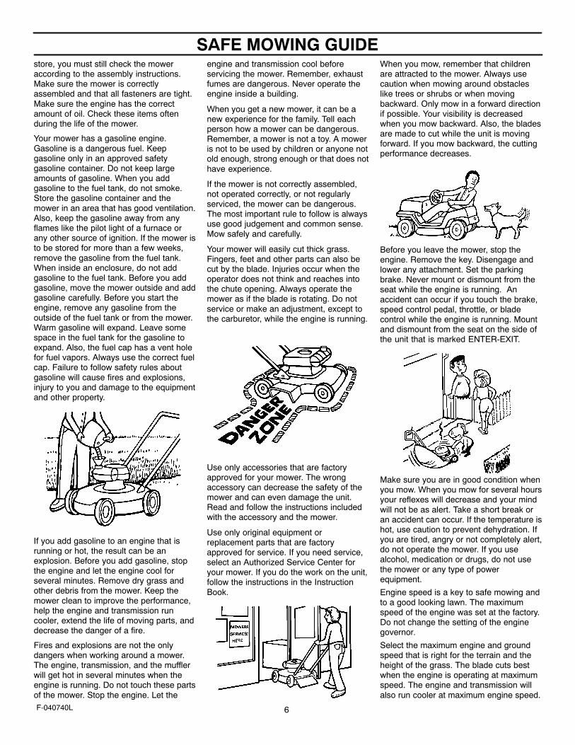
Your mower has a gasoline engine.Gasoline is a dangerous fuel. Keepgasoline only in an approved safetygasoline container. Do not keep largeamounts of gasoline. When you addgasoline to the fuel tank, do not smoke.Store the gasoline container and themower in an area that has good ventilation.Also, keep the gasoline away from anyflames like the pilot light of a furnace orany other source of ignition. If the mower isto be stored for more than a few weeks,remove the gasoline from the fuel tank.When inside an enclosure, do not addgasoline to the fuel tank. Before you addgasoline, move the mower outside and addgasoline carefully. Before you start theengine, remove any gasoline from theoutside of the fuel tank or from the mower.Warm gasoline will expand. Leave somespace in the fuel tank for the gasoline toexpand. Also, the fuel cap has a vent holefor fuel vapors. Always use the correct fuelcap. Failure to follow safety rules aboutgasoline will cause fires and explosions,injury to you and damage to the equipmentand other property.
If you add gasoline to an engine that isrunning or hot, the result can be anexplosion. Before you add gasoline, stopthe engine and let the engine cool forseveral minutes. Remove dry grass andother debris from the mower. Keep themower clean to improve the performance,help the engine and transmission runcooler, extend the life of moving parts, anddecrease the danger of a fire.
Fires and explosions are not the onlydangers when working around a mower.The engine, transmission, and the mufflerwill get hot in several minutes when theengine is running. Do not touch these partsof the mower. Stop the engine. Let the
engine and transmission cool beforeservicing the mower. Remember, exhaustfumes are dangerous. Never operate theengine inside a building.
When you get a new mower, it can be anew experience for the family. Tell eachperson how a mower can be dangerous.Remember, a mower is not a toy. A moweris not to be used by children or anyone notold enough, strong enough or that does nothave experience.
If the mower is not correctly assembled,not operated correctly, or not regularlyserviced, the mower can be dangerous.The most important rule to follow is alwaysuse good judgement and common sense.Mow safely and carefully.
Your mower will easily cut thick grass.Fingers, feet and other parts can also becut by the blade. Injuries occur when theoperator does not think and reaches intothe chute opening. Always operate themower as if the blade is rotating. Do notservice or make an adjustment, except tothe carburetor, while the engine is running.
Use only accessories that are factoryapproved for your mower. The wrongaccessory can decrease the safety of themower and can even damage the unit.Read and follow the instructions includedwith the accessory and the mower.
Use only original equipment orreplacement parts that are factoryapproved for service. If you need service,select an Authorized Service Center foryour mower. If you do the work on the unit,follow the instructions in the InstructionBook.
When you mow, remember that childrenare attracted to the mower. Always usecaution when mowing around obstacleslike trees or shrubs or when movingbackward. Only mow in a forward directionif possible. Your visibility is decreasedwhen you mow backward. Also, the bladesare made to cut while the unit is movingforward. If you mow backward, the cuttingperformance decreases.
Before you leave the mower, stop theengine. Remove the key. Disengage andlower any attachment. Set the parkingbrake. Never mount or dismount from theseat while the engine is running. Anaccident can occur if you touch the brake,speed control pedal, throttle, or bladecontrol while the engine is running. Mountand dismount from the seat on the side ofthe unit that is marked ENTER-EXIT.
Make sure you are in good condition whenyou mow. When you mow for several hoursyour reflexes will decrease and your mindwill not be as alert. Take a short break oran accident can occur. If the temperature ishot, use caution to prevent dehydration. Ifyou are tired, angry or not completely alert,do not operate the mower. If you usealcohol, medication or drugs, do not usethe mower or any type of powerequipment.
Engine speed is a key to safe mowing andto a good looking lawn. The maximumspeed of the engine was set at the factory.Do not change the setting of the enginegovernor.
Select the maximum engine and groundspeed that is right for the terrain and theheight of the grass. The blade cuts bestwhen the engine is operating at maximumspeed. The engine and transmission willalso run cooler at maximum engine speed.
SAFE MOWING GUIDE
7F-040740L
Also, the grass bagger will function betterwhen the engine is operating at maximumspeed. On slopes, decrease the groundspeed and use care making sure themower feels safe to operate.
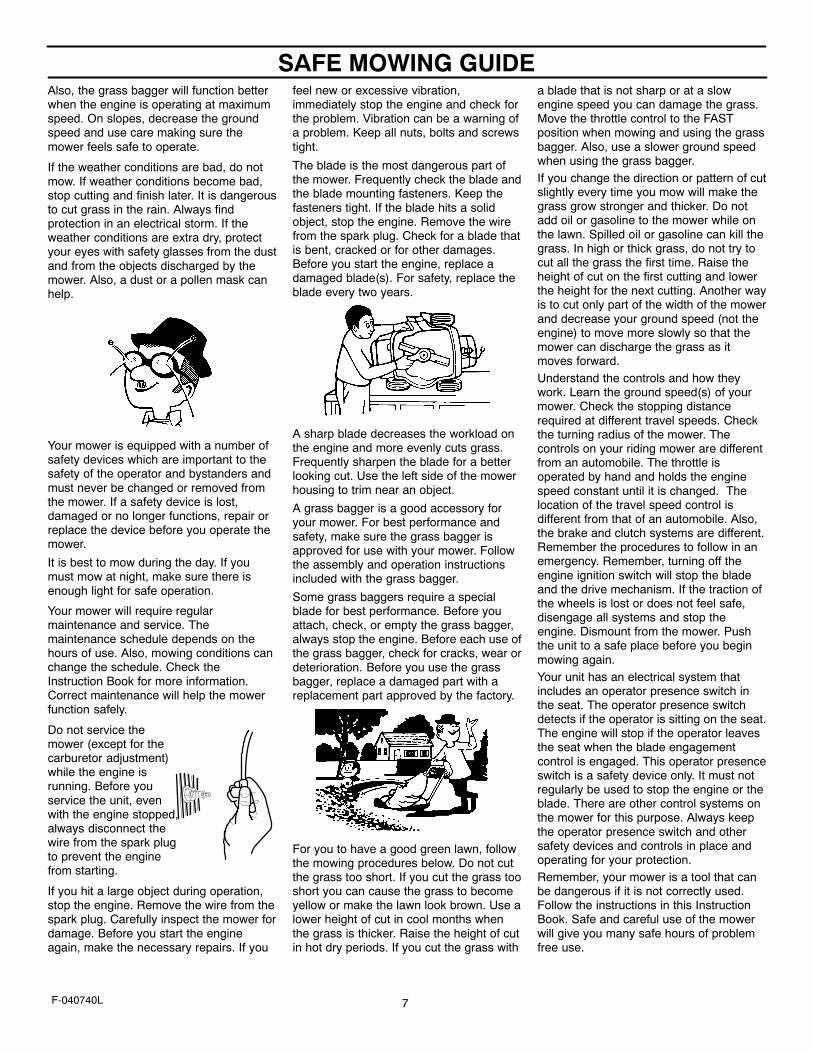
If the weather conditions are bad, do notmow. If weather conditions become bad,stop cutting and finish later. It is dangerousto cut grass in the rain. Always findprotection in an electrical storm. If theweather conditions are extra dry, protectyour eyes with safety glasses from the dustand from the objects discharged by themower. Also, a dust or a pollen mask canhelp.
Your mower is equipped with a number ofsafety devices which are important to thesafety of the operator and bystanders andmust never be changed or removed fromthe mower. If a safety device is lost,damaged or no longer functions, repair orreplace the device before you operate themower.
It is best to mow during the day. If youmust mow at night, make sure there isenough light for safe operation.
Your mower will require regularmaintenance and service. Themaintenance schedule depends on thehours of use. Also, mowing conditions canchange the schedule. Check theInstruction Book for more information.Correct maintenance will help the mowerfunction safely.
Do not service themower (except for thecarburetor adjustment)while the engine isrunning. Before youservice the unit, evenwith the engine stopped,always disconnect thewire from the spark plugto prevent the enginefrom starting.
If you hit a large object during operation,stop the engine. Remove the wire from thespark plug. Carefully inspect the mower fordamage. Before you start the engineagain, make the necessary repairs. If you
feel new or excessive vibration,immediately stop the engine and check forthe problem. Vibration can be a warning ofa problem. Keep all nuts, bolts and screwstight.
The blade is the most dangerous part ofthe mower. Frequently check the blade andthe blade mounting fasteners. Keep thefasteners tight. If the blade hits a solidobject, stop the engine. Remove the wirefrom the spark plug. Check for a blade thatis bent, cracked or for other damages.Before you start the engine, replace adamaged blade(s). For safety, replace theblade every two years.
A sharp blade decreases the workload onthe engine and more evenly cuts grass.Frequently sharpen the blade for a betterlooking cut. Use the left side of the mowerhousing to trim near an object.
A grass bagger is a good accessory foryour mower. For best performance andsafety, make sure the grass bagger isapproved for use with your mower. Followthe assembly and operation instructionsincluded with the grass bagger.
Some grass baggers require a specialblade for best performance. Before youattach, check, or empty the grass bagger,always stop the engine. Before each use ofthe grass bagger, check for cracks, wear ordeterioration. Before you use the grassbagger, replace a damaged part with areplacement part approved by the factory.
For you to have a good green lawn, followthe mowing procedures below. Do not cutthe grass too short. If you cut the grass tooshort you can cause the grass to becomeyellow or make the lawn look brown. Use alower height of cut in cool months whenthe grass is thicker. Raise the height of cutin hot dry periods. If you cut the grass with
a blade that is not sharp or at a slowengine speed you can damage the grass.Move the throttle control to the FASTposition when mowing and using the grassbagger. Also, use a slower ground speedwhen using the grass bagger.If you change the direction or pattern of cutslightly every time you mow will make thegrass grow stronger and thicker. Do notadd oil or gasoline to the mower while onthe lawn. Spilled oil or gasoline can kill thegrass. In high or thick grass, do not try tocut all the grass the first time. Raise theheight of cut on the first cutting and lowerthe height for the next cutting. Another wayis to cut only part of the width of the mowerand decrease your ground speed (not theengine) to move more slowly so that themower can discharge the grass as itmoves forward.Understand the controls and how theywork. Learn the ground speed(s) of yourmower. Check the stopping distancerequired at different travel speeds. Checkthe turning radius of the mower. Thecontrols on your riding mower are differentfrom an automobile. The throttle isoperated by hand and holds the enginespeed constant until it is changed. Thelocation of the travel speed control isdifferent from that of an automobile. Also,the brake and clutch systems are different.Remember the procedures to follow in anemergency. Remember, turning off theengine ignition switch will stop the bladeand the drive mechanism. If the traction ofthe wheels is lost or does not feel safe,disengage all systems and stop theengine. Dismount from the mower. Pushthe unit to a safe place before you beginmowing again.Your unit has an electrical system thatincludes an operator presence switch inthe seat. The operator presence switchdetects if the operator is sitting on the seat.The engine will stop if the operator leavesthe seat when the blade engagementcontrol is engaged. This operator presenceswitch is a safety device only. It must notregularly be used to stop the engine or theblade. There are other control systems onthe mower for this purpose. Always keepthe operator presence switch and othersafety devices and controls in place andoperating for your protection.Remember, your mower is a tool that canbe dangerous if it is not correctly used.Follow the instructions in this InstructionBook. Safe and careful use of the mowerwill give you many safe hours of problemfree use.
STEPS TO FOLLOW
8F-040740L
BEFORE MOWING� Be sure to dress correctly. Wear hard shoes, not sandals or tennis shoes.
� Examine the blade. A blade that is bent, cracked, or damaged must be replaced with a factory replacement blade.
� Fill the fuel tank outside. Clean off spilled fuel.
� Read and follow the Owner’s Manual, the instructions with the engine, and the instructions with any attachments. Owner’s Manualinstructions are for your safety and the safety of others.
� Exhaust fumes are dangerous. Start the engine outside.
� Make sure all safety devices are in place and working correctly.
� Operation of the mower is only for a person that has experience.
� Wet grass can be dangerous. Let the grass dry.
� Instruct children and others to keep away from the work area.
� Never cut the grass without good light.
� Pick up loose objects. Remove them from the mowing area.
WHILE MOWING� Watch for fixed objects and avoid them. They can damage the mower or cause injury.
� A hot engine, muffler, and transmission will cause a burn. Do not touch.
� Inclines and slopes must be carefully mowed. See the “Guide” in the back of this book to check a slope.
� Lack of daylight or good artificial light is cause to stop mowing.
� Examine the mower, the blade, and other parts for damage after hitting a foreign object or if the unit vibrates excessively.
� Do not make adjustments or repairs without stopping the engine. Disconnect the spark plug wire.
� On or near roads, watch out for traffic. Direct discharge away from roads.
� When mowing, avoid areas where traction is unsure. Look back before changing direction of travel.
� In heavy grass, raise the cutting height. Cut slower. Stop the engine to remove clogged grass from the mower.
� Never remove any safety related parts.
� Do not pour gasoline into a engine that is hot or running.
AFTER MOWING� Always let the mower cool before storing in an enclosed area.
� Foreign material on the mower is dangerous. Clean off grass, leaves, grease and oil before storing.
� Tighten all loose nuts, bolts and screws before you use the unit.
� Empty and clean any grass catcher or other accessory.
� Remove the key or disconnect the spark plug wire to prevent unauthorized use.
� Make sure the mower is not kept near a source of ignition. Gas fumes can cause an explosion.
� Only original parts or factory approved substitutes can be used to service the mower.
� When storing the mower for an extended period, remove the fuel from the fuel tank.
� Instruct children to leave the mower alone. It is not a toy.
� Never keep gasoline near a source of ignition. Always use an approved container. Keep gasoline away from children.
� Lubricate according to the Instruction Book. See “Lubrication”.
IMPORTANT--Read the Instruction Book. Keep this book for future use and reference.
WARNING: Look for this symbol to point out importantsafety precautions. It means: “Attention! Become Alert!Your Safety Is Involved.”
INTERNATIONAL PICTORIALS
9F-040740L
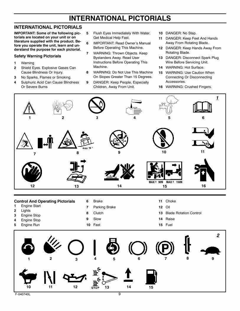
INTERNATIONAL PICTORIALSIMPORTANT: Some of the following pic-torials are located on your unit or onliterature supplied with the product. Be-fore you operate the unit, learn and un-derstand the purpose for each pictorial.
Safety Warning Pictorials
1 Warning2 Shield Eyes. Explosive Gases Can
Cause Blindness Or Injury.3 No Sparks, Flames or Smoking.4 Sulphuric Acid Can Cause Blindness
Or Severe Burns
5 Flush Eyes Immediately With Water.Get Medical Help Fast.
6 IMPORTANT: Read Owner’s ManualBefore Operating This Machine.
7 WARNING: Thrown Objects. KeepBystanders Away. Read UserInstructions Before Operating ThisMachine.
8 WARNING: Do Not Use This MachineOn Slopes Greater Than 15 Degrees.
9 DANGER: Keep People, EspeciallyChildren, Away From Unit.
10 DANGER: No Step.
11 DANGER: Keep Feet And HandsAway From Rotating Blade.
12 DANGER: Keep Hands Away FromRotating Blade.
13 DANGER: Disconnect Spark PlugWire Before Servicing Unit.
14 WARNING: Hot Surface.
15 WARNING: Use Caution WhenConnecting Or DisconnectingAccessories.
16 WARNING: Crushed Fingers.
MAX 90N+ MAX 150N+
1 2 3 54 6
7 8 9 10
12
11
13 14 15 16
1
Control And Operating Pictorials1 Engine Start2 Lights3 Engine Stop4 Engine Stop5 Engine Run
6 Brake
7 Parking Brake
8 Clutch
9 Slow
10 Fast
11 Choke
12 Oil
13 Blade Rotation Control
14 Raise
15 Fuel
1 2 3 4 5 6 7 8 9
10 11 12 13 14 15
2
ASSEMBLY
10F-040740L
ASSEMBLYThis instruction book is for several models. Some parts or accesso-ries are not included on all models. Read and follow the assemblyand adjustment instructions for your mower. All fasteners are in theparts bag. Do not discard any parts or material until the unit isassembled.
WARNING: Before doing any assembly or mainte-nance to the mower, remove the wire from the sparkplug.
NOTE: In this instruction book, left and right describe the loca-tion of a part with the operator on the seat.
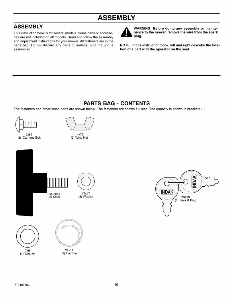
PARTS BAG - CONTENTSThe fasteners and other loose parts are shown below. The fasteners are shown full size. The quantity is shown in brackets ( ).
2x82(2) Carriage Bolt
14x79(2) Wing Nut
17x47(2) Washer 20729
(1) Keys & Ring
1001054(2) Knob
31x11(2) Hair Pin
17x91(4) Washer
ASSEMBLY
11F-040740L
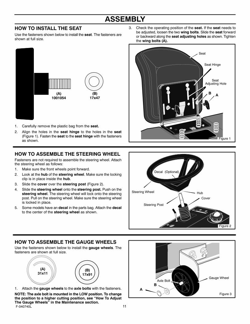
HOW TO INSTALL THE SEATUse the fasteners shown below to install the seat. The fasteners areshown at full size.
(A)1001054
(B)17x47
1. Carefully remove the plastic bag from the seat.
2. Align the holes in the seat hinge to the holes in the seat(Figure 1). Fasten the seat to the seat hinge with the fastenersas shown.
3. Check the operating position of the seat. If the seat needs tobe adjusted, loosen the two wing bolts. Slide the seat forwardor backward along the seat adjusting holes as shown. Tightenthe wing bolts (A).
Figure 1
Seat
Seat Adjusting Hole
Seat Hinge
AB
HOW TO ASSEMBLE THE STEERING WHEELFasteners are not required to assemble the steering wheel. Attachthe steering wheel as follows:1. Make sure the front wheels point forward.2. Look at the hub of the steering wheel. Make sure the locking
clip is in place inside the hub.3. Slide the cover over the steering post (Figure 2).4. Slide the steering wheel onto the steering post. Push on the
steering wheel. The steering wheel will lock onto the steeringpost. Pull on the steering wheel. Make sure the steering wheelis locked in place.
5. Some models have an decal in the parts bag. Attach the decalto the center of the steering wheel as shown.
Steering Wheel
Steering Post
Cover
Decal (Optional)
Figure 2
Hub
HOW TO ASSEMBLE THE GAUGE WHEELSUse the fasteners shown below to install the gauge wheels. Thefasteners are shown at full size.
(A)31x11
(B)17x91
1. Attach the gauge wheels to the axle bolts with the fasteners.
NOTE: The axle bolt is mounted in the LOW position. To changethe position to a higher cutting position, see “How To AdjustThe Gauge Wheels” in the Maintenance section.
Gauge Wheel
Figure 3
Axle Bolt
AB

ASSEMBLY
12F-040740L
MAINTENANCE FREE BATTERYIMPORTANT: Before you attach the battery cables to thebattery, check the battery date. The battery date tells if thebattery must be charged.
1. Check the top of the battery for the location of the battery date(Figure 4).
2. If the battery is put into service before the battery date, thebattery cables can be attached without charging the battery.See “How To Install The Battery Cables”.
3. If the battery is put into service after the battery date, thebattery must be charged. See “How To Charge TheMaintenance Free Battery”.
HOW TO CHARGE THE MAINTENANCE FREE BATTERY
WARNING: When you charge the battery, do notsmoke. Keep the battery away from any sparks. Thefumes from the battery acid can cause an explosion.
1. Remove the battery and battery tray.
2. Remove the protective caps from the battery terminals.
3. Use a 12 volt battery charger to charge the battery. Charge ata rate of 6 amperes for one hour. If you do not have a batterycharger, have an authorized service center charge the battery.
4. Install the battery and battery tray. Make sure the positive (+)terminal is on the left side.
HOW TO INSTALL THE BATTERY CABLES
WARNING: To prevent sparks, fasten the red cable tothe positive (+) terminal before you connect the blackcable.
Use the fasteners shown below to install the battery cables. Thefasteners are shown at full size.
(B)14x79
(A)2x82
1. Remove the protective caps from the battery terminals.
2. Fasten the red cable to the positive (+) terminal with thefasteners as shown (Figure 4).
3. Fasten the black cable to the negative (-) terminal with thefasteners as shown.
B
A
Positive (+)Terminal
Black Cable
Red Cable
Battery Tray
A
Battery
Figure 4
ASSEMBLY
13F-040740L
IMPORTANT! BEFORE YOU START MOWING� Check the engine oil.
� Fill the fuel tank with gasoline.
� Check the level of the mower housing.
� Check the air pressure of the tires.
� Make sure the battery cables are attached.
WARNING: Before doing any assembly or mainte-nance to the mower, remove the wire from the sparkplug.
NOTE: In this instruction book, left and right describe the loca-tion of a part with the operator on the seat.
HOW TO PREPARE THE ENGINE
NOTE: The engine was shipped from the factory filled with oil.Check the level of the oil. Add oil as needed.See the engine manufacturer’s instructions for the type of gasolineand oil to use. Before you use the unit, read the information onsafety, operation, maintenance, and storage.
WARNING: Follow the engine manufacturer’sinstructions for the type of gasoline and oil to use.Always use a safety gasoline container. Do notsmoke when adding gasoline to the engine. Wheninside an enclosure, do not fill with gasoline. Beforeyou add gasoline, stop the engine. Let the enginecool for several minutes.
IMPORTANT: This unit is equipped with an internal combustionengine and must not be used on or near any unimproved
forest-covered, brush-covered or grass-covered land unlessthe engine’s exhaust system is equipped with a spark arrestermeeting applicable local or state laws (if any). If a sparkarrester is used, it must be maintained in effective workingorder by the operator.
In the State of California the above is required by law (Section4442 of the California Public Resources Code). Other statesmay have similar laws. Federal laws apply on federal lands.See an Authorized Service Center for a spark arrester for themuffler.
In some areas, local law requires the use of a resistor sparkplug to control the ignition signals. See an Authorized ServiceCenter for a resistor spark plug for the engine.
NOTE: Actual sustained horsepower will likely be lower due tooperating limitations and environmental factors.
CHECK THE LEVEL OF THE MOWER HOUSING
Make sure the level of cut is still correct. After you mow a shortdistance, look at the area that was cut. If the mower housing doesnot cut level, see the instructions on “How To Level The MowerHousing” in the Maintenance section of this instruction book.
CHECK THE TIRES
Check the air pressure in the tires. Tires with too much air pressurewill cause the unit to ride rough. Also, the wrong air pressure willkeep the mower housing from cutting level. The correct air pressure(PSI) is 14 PSI (1 BAR). The tires were over inflated for shipment.
OPERATION
14F-040740L
Figure 5
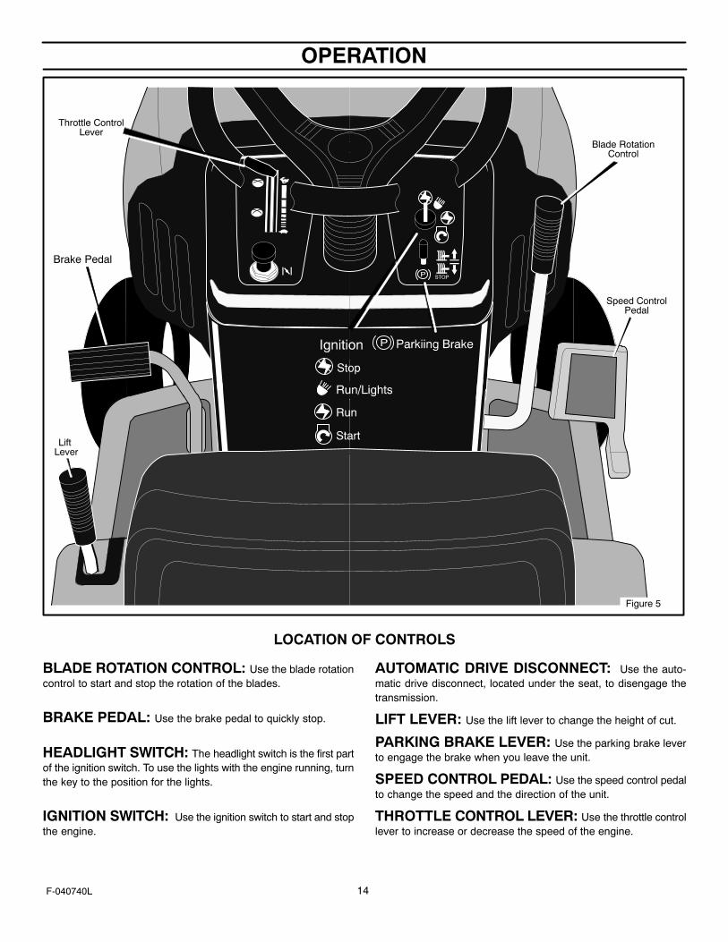
Throttle ControlLever
Blade RotationControl
Brake Pedal
Lift Lever
Speed ControlPedal
LOCATION OF CONTROLS
BLADE ROTATION CONTROL: Use the blade rotationcontrol to start and stop the rotation of the blades.
BRAKE PEDAL: Use the brake pedal to quickly stop.
HEADLIGHT SWITCH: The headlight switch is the first partof the ignition switch. To use the lights with the engine running, turnthe key to the position for the lights.
IGNITION SWITCH: Use the ignition switch to start and stopthe engine.
AUTOMATIC DRIVE DISCONNECT: Use the auto-matic drive disconnect, located under the seat, to disengage thetransmission.
LIFT LEVER: Use the lift lever to change the height of cut.
PARKING BRAKE LEVER: Use the parking brake leverto engage the brake when you leave the unit.
SPEED CONTROL PEDAL: Use the speed control pedalto change the speed and the direction of the unit.
THROTTLE CONTROL LEVER: Use the throttle controllever to increase or decrease the speed of the engine.

OPERATION
15F-040740L
ATTACHMENTS
This unit can use many different attachments. See the attachmentpage in this book. This unit can pull attachments like a lawnsweeper, a lawn aerator, a hopper spreader or a small trailer. Thisunit can not use attachments that engage the ground like a plow, adisk harrow, or a cultivator.
For all pull-behind attachments or trailers, the maximum grossweight is 250 pounds. Gross weight is the weight of the attachmentor trailer and any load that might be on or in it.
Do not operate on a slope that is greater than 10 degrees whenusing a pull-behind attachment or trailer. We have included a slopeguide in this book to help you determine the slope on which you willbe operating your unit. Never allow someone to stand or ride on orin an attachment or trailer.
HOW TO USE THE THROTTLE CONTROL
Use the throttle control to increase or decrease the speed of theengine.
CAUTION: Always operate the engine with the throttle controlin the FAST position. If the engine runs for several minutes atslower than the FAST position, the engine and transmissionwill overheat and can be damaged.
1. The FAST position is marked with a detent. For normal opera-tion and when using a grass bagger, move the throttle controlto the FAST position. For maximum charging of the battery andfor a cooler running engine and transmission, operate the en-gine in the FAST position.
2. For transport and to tow pull behind attachments, control theground speed with the speed control pedal.
3. The engine governor is set at the factory for maximum perform-ance. Do not adjust the governor to increase the speed of theengine.
HOW TO USE THE BLADE ROTATION CONTROL
The blade rotation control is next to the steering wheel (Figure 6).Use the blade rotation control to engage the blade(s) or to operatea snow thrower attachment.
1. Before you start the engine, make sure the blade rotation con-trol is in the DISENGAGE position.
2. Move the blade rotation control to the ENGAGE position torotate the blade(s).
Note: If the engine stops when you engage the blade(s),the seat switch is not activated. Make sure you sit in themiddle of the seat. Also, make sure the wire is connectedto the seat switch.
3. Move the blade rotation control to the DISENGAGE positionto stop the blade(s). Before you leave the operator’s position,make sure the blade(s) has stopped rotating.
4. Before you ride the unit across a sidewalk or a road, move theblade rotation control to the DISENGAGE position.
WARNING: Always keep your hands and feet awayfrom the blade, deflector opening, and the mowerhousing when the engine runs.
Blade Rotation ControlEngage Position
DisengagePosition
Figure 6
OPERATION
16F-040740L
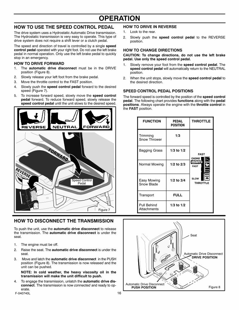
HOW TO USE THE SPEED CONTROL PEDALThe drive system uses a Hydrostatic Automatic Drive transmission.The Hydrostatic transmission is very easy to operate. This type ofdrive system does not require a shift lever or a clutch pedal.
The speed and direction of travel is controlled by a single speedcontrol pedal operated with your right foot. Do not use the left brakepedal in normal operation. Only use the left brake pedal to quicklystop in an emergency.
HOW TO DRIVE FORWARD1. The automatic drive disconnect must be in the DRIVE
position (Figure 8).2. Slowly release your left foot from the brake pedal.3. Move the throttle control to the FAST position.4. Slowly push the speed control pedal forward to the desired
speed (Figure 7).5. To increase forward speed, slowly move the speed control
pedal forward. To reduce forward speed, slowly release thespeed control pedal until the unit slows to the desired speed.
Speed ControlPedal
Figure 7
HOW TO DRIVE IN REVERSE1. Look to the rear.
2. Slowly push the speed control pedal to the REVERSEposition.
HOW TO CHANGE DIRECTIONSCAUTION: To change directions, do not use the left brakepedal. Use only the speed control pedal.
1. Slowly remove your foot from the speed control pedal. Thespeed control pedal will automatically return to the NEUTRALposition.
2. When the unit stops, slowly move the speed control pedal tothe desired direction.
SPEED CONTROL PEDAL POSITIONSThe forward speed is controlled by the position of the speed controlpedal. The following chart provides functions along with the pedalpositions. Always operate the engine with the throttle control inthe FAST position.
FUNCTION PEDALPOSITION
THROTTLE
Trimming Snow Thrower
1/3
Bagging Grass 1/3 to 1/2FAST
CHOKE
Normal Mowing 1/2 to 2/3
CHOKE
FAST
Easy MowingSnow Blade
1/2 to 3/4 SLOW
THROTTLE
Transport FULL
Pull BehindAttachments
1/3 to 1/2
HOW TO DISCONNECT THE TRANSMISSION
To push the unit, use the automatic drive disconnect to releasethe transmission. The automatic drive disconnect is under theseat.
1. The engine must be off.
2. Raise the seat. The automatic drive disconnect is under theseat.
3. Move and latch the automatic drive disconnect in the PUSHposition (Figure 8). The transmission is now released and theunit can be pushed.
NOTE: In cold weather, the heavy viscosity oil in thetransmission will make the unit difficult to push.
4. To engage the transmission, unlatch the automatic drive dis-connect. The transmission is now connected and ready to op-erate.
Figure 8Automatic Drive Disconnect
Seat
DRIVE POSITIONAutomatic Drive Disconnect
PUSH POSITION
OPERATION
17F-040740L
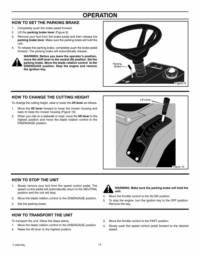
HOW TO SET THE PARKING BRAKE1. Completely push the brake pedal forward.2. Lift the parking brake lever (Figure 9).
3. Remove your foot from the brake pedal and then release theparking brake lever. Make sure the parking brake will hold theunit.
4. To release the parking brake, completely push the brake pedalforward. The parking brake will automatically release.
WARNING: Before you leave the operator’s position,move the shift lever to the neutral (N) position. Set theparking brake. Move the blade rotation control to theDISENGAGE position. Stop the engine and removethe ignition key.
Figure 9
Parking Brake
HOW TO CHANGE THE CUTTING HEIGHTTo change the cutting height, raise or lower the lift lever as follows.
1. Move the lift lever forward to lower the mower housing andback to raise the mower housing (Figure 10).
2. When you ride on a sidewalk or road, move the lift lever to thehighest position and move the blade rotation control to theDISENGAGE position.
Lift Lever
Figure 10
HOW TO STOP THE UNIT1. Slowly remove your foot from the speed control pedal. The
speed control pedal will automatically return to the NEUTRALposition and the unit will stop.
2. Move the blade rotation control to the DISENGAGE position.
3. Set the parking brake.
WARNING: Make sure the parking brake will hold theunit.
4. Move the throttle control to the SLOW position.5. To stop the engine, turn the ignition key to the OFF position.
Remove the key.
HOW TO TRANSPORT THE UNITTo transport the unit, follow the steps below.1. Move the blade rotation control to the DISENGAGE position2. Raise the lift lever to the highest position.
3. Move the throttle control to the FAST position.
4. Slowly push the speed control pedal forward to the desiredspeed.
OPERATION
18F-040740L
HOW TO OPERATE WITH THE MOWER HOUSING
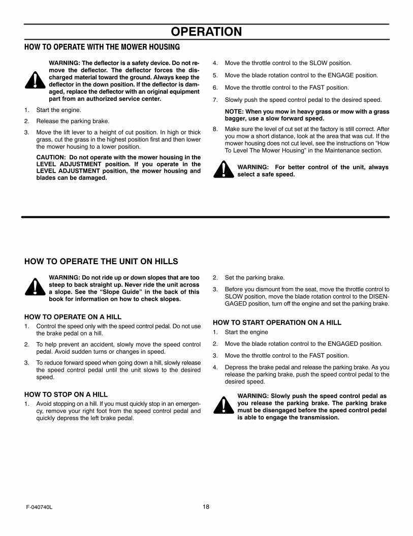
WARNING: The deflector is a safety device. Do not re-move the deflector. The deflector forces the dis-charged material toward the ground. Always keep thedeflector in the down position. If the deflector is dam-aged, replace the deflector with an original equipmentpart from an authorized service center.
1. Start the engine.
2. Release the parking brake.
3. Move the lift lever to a height of cut position. In high or thickgrass, cut the grass in the highest position first and then lowerthe mower housing to a lower position.
CAUTION: Do not operate with the mower housing in theLEVEL ADJUSTMENT position. If you operate in theLEVEL ADJUSTMENT position, the mower housing andblades can be damaged.
4. Move the throttle control to the SLOW position.
5. Move the blade rotation control to the ENGAGE position.
6. Move the throttle control to the FAST position.
7. Slowly push the speed control pedal to the desired speed.
NOTE: When you mow in heavy grass or mow with a grassbagger, use a slow forward speed.
8. Make sure the level of cut set at the factory is still correct. Afteryou mow a short distance, look at the area that was cut. If themower housing does not cut level, see the instructions on “HowTo Level The Mower Housing” in the Maintenance section.
WARNING: For better control of the unit, alwaysselect a safe speed.
HOW TO OPERATE THE UNIT ON HILLS
WARNING: Do not ride up or down slopes that are toosteep to back straight up. Never ride the unit acrossa slope. See the “Slope Guide” in the back of thisbook for information on how to check slopes.
HOW TO OPERATE ON A HILL1. Control the speed only with the speed control pedal. Do not use
the brake pedal on a hill.
2. To help prevent an accident, slowly move the speed controlpedal. Avoid sudden turns or changes in speed.
3. To reduce forward speed when going down a hill, slowly releasethe speed control pedal until the unit slows to the desiredspeed.
HOW TO STOP ON A HILL1. Avoid stopping on a hill. If you must quickly stop in an emergen-
cy, remove your right foot from the speed control pedal andquickly depress the left brake pedal.
2. Set the parking brake.
3. Before you dismount from the seat, move the throttle control toSLOW position, move the blade rotation control to the DISEN-GAGED position, turn off the engine and set the parking brake.
HOW TO START OPERATION ON A HILL1. Start the engine
2. Move the blade rotation control to the ENGAGED position.
3. Move the throttle control to the FAST position.
4. Depress the brake pedal and release the parking brake. As yourelease the parking brake, push the speed control pedal to thedesired speed.
WARNING: Slowly push the speed control pedal asyou release the parking brake. The parking brakemust be disengaged before the speed control pedalis able to engage the transmission.
OPERATION
19F-040740L
BEFORE STARTING THE ENGINE
CHECK THE OILNOTE: The engine was shipped from the factory filled with oil.Check the level of the oil. Add oil as needed. See the enginemanufacturer’s instructions for the type of gasoline and oil touse.
1. Make sure the unit is level.
NOTE: Do not check the level of the oil while the engineruns.
2. Check the oil. Follow the procedure in the engine manufactur-er’s instructions.
3. If necessary, add oil until the oil reaches the FULL mark on thedipstick. The quantity of oil needed from ADD to FULL is shownon the dipstick. Do not add too much oil.
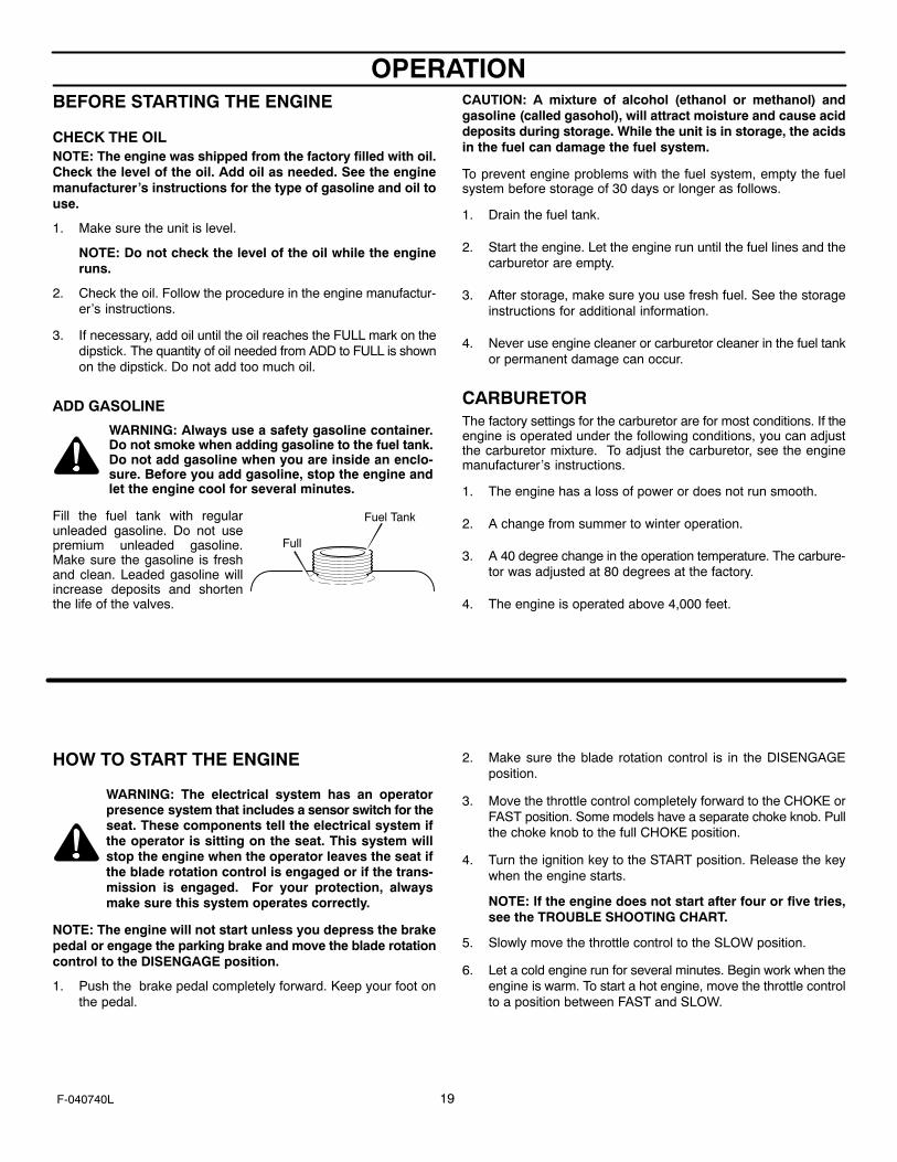
ADD GASOLINE
WARNING: Always use a safety gasoline container.Do not smoke when adding gasoline to the fuel tank.Do not add gasoline when you are inside an enclo-sure. Before you add gasoline, stop the engine andlet the engine cool for several minutes.
Fill the fuel tank with regularunleaded gasoline. Do not usepremium unleaded gasoline.Make sure the gasoline is freshand clean. Leaded gasoline willincrease deposits and shortenthe life of the valves.
CAUTION: A mixture of alcohol (ethanol or methanol) andgasoline (called gasohol), will attract moisture and cause aciddeposits during storage. While the unit is in storage, the acidsin the fuel can damage the fuel system.
To prevent engine problems with the fuel system, empty the fuelsystem before storage of 30 days or longer as follows.
1. Drain the fuel tank.
2. Start the engine. Let the engine run until the fuel lines and thecarburetor are empty.
3. After storage, make sure you use fresh fuel. See the storageinstructions for additional information.
4. Never use engine cleaner or carburetor cleaner in the fuel tankor permanent damage can occur.
CARBURETORThe factory settings for the carburetor are for most conditions. If theengine is operated under the following conditions, you can adjustthe carburetor mixture. To adjust the carburetor, see the enginemanufacturer’s instructions.
1. The engine has a loss of power or does not run smooth.
2. A change from summer to winter operation.
3. A 40 degree change in the operation temperature. The carbure-tor was adjusted at 80 degrees at the factory.
4. The engine is operated above 4,000 feet.
HOW TO START THE ENGINE
WARNING: The electrical system has an operatorpresence system that includes a sensor switch for theseat. These components tell the electrical system ifthe operator is sitting on the seat. This system willstop the engine when the operator leaves the seat ifthe blade rotation control is engaged or if the trans-mission is engaged. For your protection, alwaysmake sure this system operates correctly.
NOTE: The engine will not start unless you depress the brakepedal or engage the parking brake and move the blade rotationcontrol to the DISENGAGE position.
1. Push the brake pedal completely forward. Keep your foot onthe pedal.
2. Make sure the blade rotation control is in the DISENGAGEposition.
3. Move the throttle control completely forward to the CHOKE orFAST position. Some models have a separate choke knob. Pullthe choke knob to the full CHOKE position.
4. Turn the ignition key to the START position. Release the keywhen the engine starts.
NOTE: If the engine does not start after four or five tries,see the TROUBLE SHOOTING CHART.
5. Slowly move the throttle control to the SLOW position.
6. Let a cold engine run for several minutes. Begin work when theengine is warm. To start a hot engine, move the throttle controlto a position between FAST and SLOW.
Fuel Tank
Full

OPERATION
20F-040740L
OPERATING TIPS
1. Check the blade rotation control for correct adjustment. For theblade(s) to disengage correctly, the adjustment must be cor-rect.
2. Before you use the unit, check the oil in the engine and add oilif necessary.
3. If the engine will not start, first make sure the wire is attachedto the spark plug.
4. Make sure all the belts are inside all the belt guides. See the in-structions on how to remove and install the motion drive andmower drive belts.
5. Before you make an inspection, adjustment (except for the car-buretor) or repair, make sure the wire from the spark plug is dis-connected.
6. For longer life of the battery on electric start models, charge thebattery every three months.
7. Use the speed control pedal to change the ground speed, notthe throttle control.
8. Belt noise can occur when the blade is engaged. This noise isnormal and does not affect the operation of the unit.
MOWING AND BAGGING TIPS
1. For a lawn to look better, check the cutting level of the mowerhousing. See “How To Level The Mower Housing” in the Main-tenance section.
2. For the mower housing to cut level, make sure the tires havethe correct amount of air pressure.
3. Every time you use the unit, check the blade. If the blade is bentor damaged, immediately replace the blade. Also, make surethe nut for the blade is tight.
4. Keep the blade(s) sharpened. Worn blades will cause the endsof the grass to turn brown.
5. Do not cut or bag grass that is wet. Wet grass will not dischargecorrectly. Let the grass dry before cutting.
6. Use the left side of the mower housing to trim near an object.
7. Discharge the cut grass onto the mowed area. The result is amore even discharge of cut grass.
8. When you mow large areas, start by turning to the right so thatthe cut grass will discharge away from shrubs, fences, drive-ways, etc. After one or two rounds, mow in the opposite direc-tion making left turns until finished (Figure 11).
9. If the grass is very high, cut two times to decrease the load onthe engine. First cut with the mower housing in the highest posi-tion and then lower the mower housing for the second cut.
10. For better engine performance and an even discharge of thecut grass, always operate the engine with the throttle in FASTposition.
11. When you use a bagger, operate the engine with the throttle inFAST position and the speed control pedal pushed 1/3 forward.
12. For better cutting performance and a quality cut, mow with thespeed control pedal pushed 1/3 to 1/2 forward.
13. After each use, clean the bottom and top of the mower housingfor better performance. Also, a clean mower housing will helpprevent a fire.
Figure 11
MAINTENANCE
21F-040740L
MAINTENANCE CHART
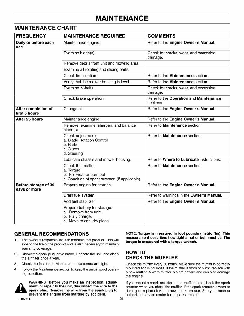
FREQUENCY MAINTENANCE REQUIRED COMMENTSDaily or before eachuse
Maintenance engine. Refer to the Engine Owner’s Manual.
Examine blade(s). Check for cracks, wear, and excessivedamage.
Remove debris from unit and mowing area.
Examine all rotating and sliding parts.
Check tire inflation. Refer to the Maintenance section.
Verify that the mower housing is level. Refer to the Maintenance section.
Examine V-belts. Check for cracks, wear, and excessivedamage.
Check brake operation. Refer to the Operation and Maintenancesections.
After completion offirst 5 hours
Change oil. Refer to the Engine Owner’s Manual.
After 25 hours Maintenance engine. Refer to the Engine Owner’s Manual.
Remove, examine, sharpen, and balanceblade(s).
Refer to Maintenance section.
Check adjustments:a. Blade Rotation Controlb. Brakec. Clutchd. Steering
Refer to Maintenance section.
Lubricate chassis and mower housing. Refer to Where to Lubricate instructions.
Check the muffler:a. Torqueb. For wear or burn outc. Condition of spark arrestor, (if applicable).
Refer to Maintenance section.
Before storage of 30days or more
Prepare engine for storage. Refer to the Engine Owner’s Manual.
Drain fuel system. Refer to warnings in the Owner’s Manual.
Add fuel stabilizer. Refer to the Engine Owner’s Manual.
Prepare battery for storage:a. Remove from unit.b. Fully charge.c. Move to cool dry place.
GENERAL RECOMMENDATIONS1. The owner’s responsibility is to maintain this product. This will
extend the life of the product and is also necessary to maintainwarranty coverage.
2. Check the spark plug, drive brake, lubricate the unit, and cleanthe air filter once a year.
3. Check the fasteners. Make sure all fasteners are tight.
4. Follow the Maintenance section to keep the unit in good operat-ing condition.
WARNING: Before you make an inspection, adjust-ment, or repair to the unit, disconnect the wire to thespark plug. Remove the wire from the spark plug toprevent the engine from starting by accident.
NOTE: Torque is measured in foot pounds (metric Nm). Thismeasurement describes how tight a nut or bolt must be. Thetorque is measured with a torque wrench.
HOW TO CHECK THE MUFFLERCheck the muffler every 50 hours. Make sure the muffler is correctlymounted and is not loose. If the muffler is worn or burnt, replace witha new muffler. A worn muffler is a fire hazard and can also damagethe engine.
If you mount a spark arrester to the muffler, also check the sparkarrester when you check the muffler. If the spark arrester is worn ordamaged, replace it with a new spark arrester. See your nearestauthorized service center for a spark arrester.
MAINTENANCE
22F-040740L
INSPECT BLADEWARNING: Before you inspect or remove the blade,disconnect the wire to the spark plug. If the blade hitsan object, stop the engine. Check the unit for dam-age. The blade has sharp edges. When you hold theblade, use gloves or cloth material to protect yourhands.
If you keep the blade sharp and inspect the blade for damage, theblade will cut better and be more safe to operate. Frequently checkthe blade for excessive wear, cracks, or other damage. Frequentlycheck the nut that holds the blade. Keep the nut tight. If the bladehits an object, stop the engine. Disconnect the wire to the spark plug.See if the blade is bent or damaged. Check the blade adapter fordamage. Before you operate the unit, replace damaged parts withoriginal equipment parts. See the authorized service center in yourarea. Every three years, have an authorized service person inspectthe blade or replace the old blade with an original equipment part.
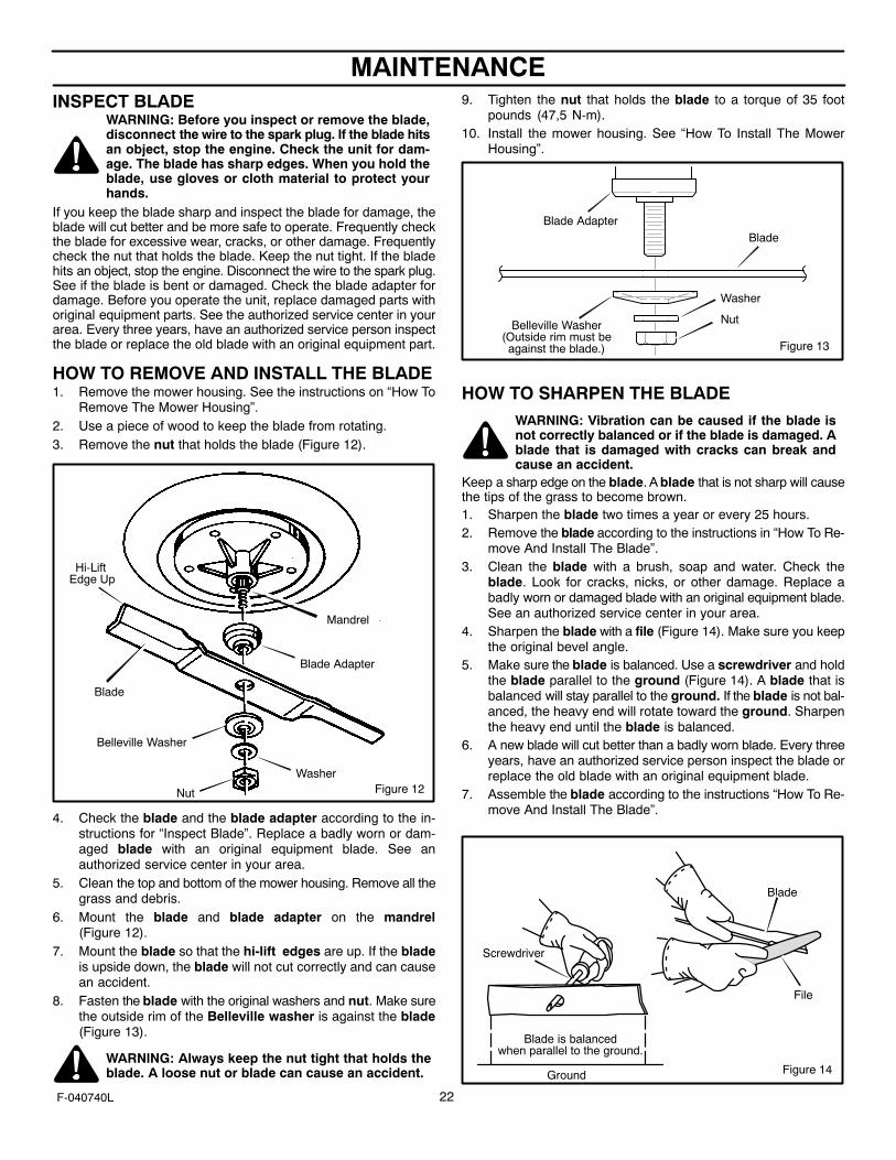
HOW TO REMOVE AND INSTALL THE BLADE1. Remove the mower housing. See the instructions on “How To
Remove The Mower Housing”.2. Use a piece of wood to keep the blade from rotating.3. Remove the nut that holds the blade (Figure 12).
Hi-LiftEdge Up
Mandrel
Blade Adapter
Blade
Belleville Washer
Washer
Nut Figure 12
4. Check the blade and the blade adapter according to the in-structions for “Inspect Blade”. Replace a badly worn or dam-aged blade with an original equipment blade. See anauthorized service center in your area.
5. Clean the top and bottom of the mower housing. Remove all thegrass and debris.
6. Mount the blade and blade adapter on the mandrel(Figure 12).
7. Mount the blade so that the hi-lift edges are up. If the bladeis upside down, the blade will not cut correctly and can causean accident.
8. Fasten the blade with the original washers and nut. Make surethe outside rim of the Belleville washer is against the blade(Figure 13).
WARNING: Always keep the nut tight that holds theblade. A loose nut or blade can cause an accident.
9. Tighten the nut that holds the blade to a torque of 35 footpounds (47,5 N-m).
10. Install the mower housing. See “How To Install The MowerHousing”.
Blade AdapterBlade
Belleville Washer(Outside rim must beagainst the blade.)
Washer
Nut
Figure 13
HOW TO SHARPEN THE BLADEWARNING: Vibration can be caused if the blade isnot correctly balanced or if the blade is damaged. Ablade that is damaged with cracks can break andcause an accident.
Keep a sharp edge on the blade. A blade that is not sharp will causethe tips of the grass to become brown.1. Sharpen the blade two times a year or every 25 hours.2. Remove the blade according to the instructions in “How To Re-
move And Install The Blade”.3. Clean the blade with a brush, soap and water. Check the
blade. Look for cracks, nicks, or other damage. Replace abadly worn or damaged blade with an original equipment blade.See an authorized service center in your area.
4. Sharpen the blade with a file (Figure 14). Make sure you keepthe original bevel angle.
5. Make sure the blade is balanced. Use a screwdriver and holdthe blade parallel to the ground (Figure 14). A blade that isbalanced will stay parallel to the ground. If the blade is not bal-anced, the heavy end will rotate toward the ground. Sharpenthe heavy end until the blade is balanced.
6. A new blade will cut better than a badly worn blade. Every threeyears, have an authorized service person inspect the blade orreplace the old blade with an original equipment blade.
7. Assemble the blade according to the instructions “How To Re-move And Install The Blade”.
Ground
Blade is balancedwhen parallel to the ground.
Screwdriver
Blade
File
Figure 14
MAINTENANCE
23F-040740L
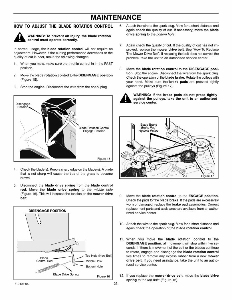
HOW TO ADJUST THE BLADE ROTATION CONTROL
WARNING: To prevent an injury, the blade rotationcontrol must operate correctly.
In normal usage, the blade rotation control will not require anadjustment. However, if the cutting performance decreases or thequality of cut is poor, make the following changes.
1. When you mow, make sure the throttle control in in the FASTposition.
2. Move the blade rotation control to the DISENGAGE position(Figure 15).
3. Stop the engine. Disconnect the wire from the spark plug.
Blade Rotation ControlEngage Position
DisengagePosition
Figure 15
4. Check the blade(s). Keep a sharp edge on the blade(s). A bladethat is not sharp will cause the tips of the grass to becomebrown.
5. Disconnect the blade drive spring from the blade controlrod. Move the blade drive spring to the middle hole(Figure 16). This will increase the tension on the mower drivebelt.
Figure 16
Blade Control Rod
Blade Drive Spring
Top Hole (New Belt)
Middle Hole
Bottom Hole
DISENGAGE POSITION
6. Attach the wire to the spark plug. Mow for a short distance andagain check the quality of cut. If necessary, move the bladedrive spring to the bottom hole.
7. Again check the quality of cut. If the quality of cut has not im-proved, replace the mower drive belt. See “How To ReplaceThe Mower Drive Belt”. If replacing the belt does not correct theproblem, take the unit to an authorized service center.
8. Move the blade rotation control to the DISENGAGE posi-tion. Stop the engine. Disconnect the wire from the spark plug.Check the operation of the blade brake. Rotate the pulleys withyour hand. Make sure the brake pads are pressed tightlyagainst the pulleys (Figure 17).
WARNING: If the brake pads do not press tightlyagainst the pulleys, take the unit to an authorizedservice center.
Blade BrakeBrake Pad
Against Pulley
Figure 17
9. Move the blade rotation control to the ENGAGE position.Check the pads for the blade brake. If the pads are excessivelyworn or damaged, replace the brake pad assemblies. Correctreplacement parts and assistance are available from an autho-rized service center.
10. Attach the wire to the spark plug. Mow for a short distance andagain check the operation of the blade rotation control.
11. When you move the blade rotation control to theDISENGAGE position, all movement will stop within five se-conds. If there is movement of the belt or the blades continueto rotate, engage and disengage the blade rotation controlfive times to remove any excess rubber from a new mowerdrive belt. If you need assistance, take the unit to an autho-rized service center.
12. If you replace the mower drive belt, move the blade drivespring to the top hole (Figure 16).
MAINTENANCE
24F-040740L
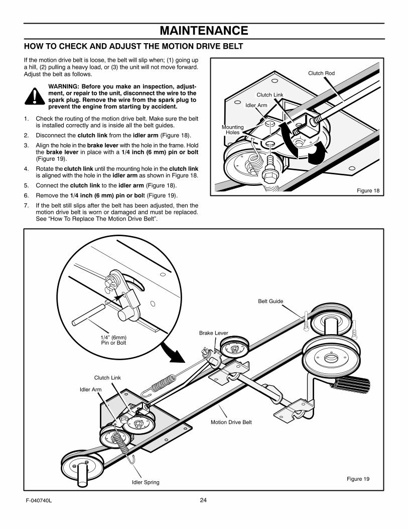
HOW TO CHECK AND ADJUST THE MOTION DRIVE BELT
If the motion drive belt is loose, the belt will slip when; (1) going upa hill, (2) pulling a heavy load, or (3) the unit will not move forward.Adjust the belt as follows.
WARNING: Before you make an inspection, adjust-ment, or repair to the unit, disconnect the wire to thespark plug. Remove the wire from the spark plug toprevent the engine from starting by accident.
1. Check the routing of the motion drive belt. Make sure the beltis installed correctly and is inside all the belt guides.
2. Disconnect the clutch link from the idler arm (Figure 18).
3. Align the hole in the brake lever with the hole in the frame. Holdthe brake lever in place with a 1/4 inch (6 mm) pin or bolt(Figure 19).
4. Rotate the clutch link until the mounting hole in the clutch linkis aligned with the hole in the idler arm as shown in Figure 18.
5. Connect the clutch link to the idler arm (Figure 18).
6. Remove the 1/4 inch (6 mm) pin or bolt (Figure 19).
7. If the belt still slips after the belt has been adjusted, then themotion drive belt is worn or damaged and must be replaced.See “How To Replace The Motion Drive Belt”.
Figure 18
Clutch Link
Clutch Rod
MountingHoles
Idler Arm
Figure 19
Belt Guide
Clutch Link
Idler Spring
Idler Arm
Motion Drive Belt
1/4” (6mm)Pin or Bolt
Brake Lever

MAINTENANCE
25F-040740L
HOW TO CHECK AND ADJUST THE DRIVE BRAKECompletely push the brake pedal forward. Set the parking brake.Move the automatic drive disconnect to the PUSH position. Pushthe unit. If the rear wheels rotate, adjust or replace the brake pads.Adjust the drive brake as follows.1. The location of the drive brake is on the right side of the
gearbox (Figure 20).2. Make sure the parking brake is set and the automatic drive
disconnect is in the PUSH position. Turn the hex nut in aclockwise direction until the rear wheels do not turn when theunit is pushed forward.
3. Release the parking brake and push the unit. If the unit does notroll, turn the hex nut in a counterclockwise direction until theunit rolls.
4. Set the parking brake. Push the unit. If the rear wheels do notturn, the drive brake is correctly adjusted. Release the parkingbrake.
WARNING: If you cannot correctly adjust the drivebrake, replace the brake pads. Correct replacementparts and assistance are available from an autho-rized service center.
Figure 20
Drive Brake
GearboxHex Nut
MAINTENANCE FREE BATTERY
HOW TO REMOVE THE BATTERY
To charge or clean the battery, remove the battery from the unit asfollows.
WARNING: To prevent sparks, disconnect the blackbattery cable from the negative (-) terminal before youdisconnect the red cable.WARNING: The battery contains sulfuric acid which isharmful to the skin, eyes and clothing. If the acid getson the body or clothing, wash with water.
1. Disconnect the black cable from the negative (-) terminal(Figure 21).
2. Disconnect the red cable from the positive (+) terminal.
3. Lift the battery tray and the battery out of the unit.
HOW TO CLEAN THE BATTERY1. Remove the battery.
2. Wash the battery with a solution of one gallon of water and fourtablespoons of baking soda (sodium bicarbonate). Make surethe solution does not get into the battery cells.
3. Clean the terminals and the ends of the cables with a wirebrush.
4. Install the battery.
5. To prevent corrosion, apply grease to the battery terminals.
HOW TO CHARGE THE BATTERY
WARNING: When you charge the battery, do notsmoke. Keep the battery away from any sparks. Thefumes from the battery acid can cause an explosion.
1. Before you charge the battery, remove the battery.
2. To charge the battery, use a 12 volt battery charger. Charge ata rate of 6 amperes for 1 hour.
3. Install the battery.
WARNING: To prevent sparks, fasten the red cable tothe positive (+) terminal before you connect the blackcable.
4. Fasten the red cable to the positive (+) terminal with the fas-teners as shown.
5. Fasten the black cable to the negative (-) terminal with the fas-teners as shown.
Positive (+)Terminal
Black Cable
Red Cable
Battery Tray
Battery
Figure 21Carriage Bolt
Wing Nut
Carriage Bolt

MAINTENANCE
26F-040740L
WHERE TO LUBRICATE
Lubricate the areas shown with engine oil.
Apply grease with a brush to the areas shown.
Models with grease fittings: Lubricate with grease gun.
NOTE: Apply grease to the steering gear assembly.CAUTION: If the unit is operated in dry areas that have sand,use a dry graphite spray to lubricate the unit.
HOW TO CHECK THE FUEL FILTERNOTE: Before you replace the fuel filter or the fuel line, the fueltank must be empty.
If the fuel filter is dirty, the engine will run rough and have lessperformance. Remove the old filter (Figure 23). Replace the oldfilter with a new filter. Use an original equipment part. See anauthorized service dealer in your area.
Fuel Line
Clips
Fuel Filter
Figure 23
CHECK THE TIRESCheck the air pressure in the tires. Tires with too much air pressurewill cause the unit to ride rough. Also, the wrong air pressure willkeep the mower housing from cutting level. The correct air pressureis 14 PSI (1 BAR).
Figure 22
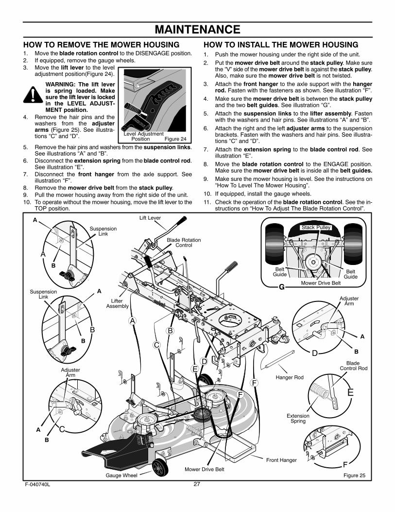
WARNING: The lift leveris spring loaded. Makesure the lift lever is lockedin the LEVEL ADJUST-MENT position.
Level AdjustmentPosition Figure 24
MAINTENANCE
27F-040740L
HOW TO REMOVE THE MOWER HOUSING1. Move the blade rotation control to the DISENGAGE position.2. If equipped, remove the gauge wheels.3. Move the lift lever to the level
adjustment position(Figure 24).
4. Remove the hair pins and thewashers from the adjusterarms (Figure 25). See illustra-tions “C” and “D”.
5. Remove the hair pins and washers from the suspension links.See illustrations “A” and “B”.
6. Disconnect the extension spring from the blade control rod.See illustration “E”.
7. Disconnect the front hanger from the axle support. Seeillustration “F”.
8. Remove the mower drive belt from the stack pulley.9. Pull the mower housing away from the right side of the unit.10. To operate without the mower housing, move the lift lever to the
TOP position.
HOW TO INSTALL THE MOWER HOUSING1. Push the mower housing under the right side of the unit.2. Put the mower drive belt around the stack pulley. Make sure
the “V” side of the mower drive belt is against the stack pulley.Also, make sure the mower drive belt is not twisted.
3. Attach the front hanger to the axle support with the hangerrod. Fasten with the fasteners as shown. See illustration “F”.
4. Make sure the mower drive belt is between the stack pulleyand the two belt guides. See illustration “G”.
5. Attach the suspension links to the lifter assembly. Fastenwith the washers and hair pins. See illustrations “A” and “B”.
6. Attach the right and the left adjuster arms to the suspensionbrackets. Fasten with the washers and hair pins. See illustra-tions “C” and “D”.
7. Attach the extension spring to the blade control rod. Seeillustration “E”.
8. Move the blade rotation control to the ENGAGE position.Make sure the mower drive belt is inside all the belt guides.
9. Make sure the mower housing is level. See the instructions on“How To Level The Mower Housing”.
10. If equipped, install the gauge wheels.11. Check the operation of the blade rotation control. See the in-
structions on “How To Adjust The Blade Rotation Control”.
Lifter Assembly
Blade RotationControl
Hanger Rod
Mower Drive Belt
Lift Lever
Front Hanger
ExtensionSpring
Blade Control Rod
SuspensionLink
AdjusterArm
BeltGuide
BeltGuide
Stack Pulley
Mower Drive Belt
SuspensionLink
A
B
A
B
A
B
A
B
AdjusterArm
Figure 25Gauge Wheel

MAINTENANCE
28F-040740L
HOW TO ADJUST THE GAUGE WHEELS
The axle bolts for the gauge wheels were mounted in the LOW cutposition. To change the position of the gauge wheels, move the axlebolts as follows.
IMPORTANT: Before you adjust the gauge wheels, you must dothe following. Make sure the mower housing is level. Make surethe height of cut is set at the height you want for your lawn.Mow a short distance on a flat level area and look at the areathat was cut. If the mower housing does not cut level, see theinstructions “How To Level The Mower Housing.”
WARNING: Before you make an inspection, adjust-ment, or repair to the unit, disconnect the wire to thespark plug. Remove the spark plug wire to preventthe engine from starting by accident.
1. Remove the gauge wheels (Figure 26).
2. Mow a short distance on a flat level area to check the level ofcut and the height of cut. Look at the height of cut positionnumber on the lift lever (Figure 27).
3. Look at each gauge wheel bracket. There are 3 holes in eachbracket and a number next to each hole. The number for theheight of cut position on the lift lever indicates the correct holeto use on each gauge wheel bracket (Figure 28).
4. Assemble the axle bolts to the gauge wheel brackets usingthe correct hole in the bracket as indicated (Figure 28).
NOTE: If the height of cut position is changed by the lift lever,you must move the gauge wheels to the correct hole(Figure 28) to keep a level height of cut.
Gauge Wheel
Figure 26
LockingRing
WasherAxle Bolt
Figure 27
Cutting Height Positions
Lift Lever
Wheel BracketHole No.
Lift LeverPosition No.
1 12 23 3,4,5,6
Figure 28
GaugeWheel Bracket
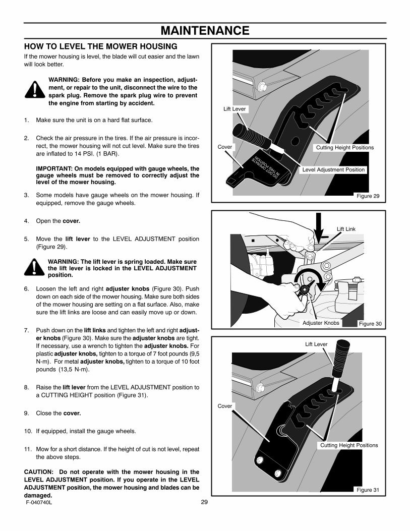
MAINTENANCE
29F-040740L
HOW TO LEVEL THE MOWER HOUSINGIf the mower housing is level, the blade will cut easier and the lawnwill look better.
WARNING: Before you make an inspection, adjust-ment, or repair to the unit, disconnect the wire to thespark plug. Remove the spark plug wire to preventthe engine from starting by accident.
1. Make sure the unit is on a hard flat surface.
2. Check the air pressure in the tires. If the air pressure is incor-rect, the mower housing will not cut level. Make sure the tiresare inflated to 14 PSI. (1 BAR).
IMPORTANT: On models equipped with gauge wheels, thegauge wheels must be removed to correctly adjust thelevel of the mower housing.
3. Some models have gauge wheels on the mower housing. Ifequipped, remove the gauge wheels.
4. Open the cover.
5. Move the lift lever to the LEVEL ADJUSTMENT position(Figure 29).
WARNING: The lift lever is spring loaded. Make surethe lift lever is locked in the LEVEL ADJUSTMENTposition.
6. Loosen the left and right adjuster knobs (Figure 30). Pushdown on each side of the mower housing. Make sure both sidesof the mower housing are setting on a flat surface. Also, makesure the lift links are loose and can easily move up or down.
7. Push down on the lift links and tighten the left and right adjust-er knobs (Figure 30). Make sure the adjuster knobs are tight.If necessary, use a wrench to tighten the adjuster knobs. Forplastic adjuster knobs, tighten to a torque of 7 foot pounds (9,5N-m). For metal adjuster knobs, tighten to a torque of 10 footpounds (13,5 N-m).
8. Raise the lift lever from the LEVEL ADJUSTMENT position toa CUTTING HEIGHT position (Figure 31).
9. Close the cover.
10. If equipped, install the gauge wheels.
11. Mow for a short distance. If the height of cut is not level, repeatthe above steps.
CAUTION: Do not operate with the mower housing in theLEVEL ADJUSTMENT position. If you operate in the LEVELADJUSTMENT position, the mower housing and blades can bedamaged.
Figure 29
Level Adjustment Position
Cutting Height PositionsCover
Lift Lever
Figure 30Adjuster Knobs
Lift Link
Figure 31
Cutting Height Positions
Cover
Lift Lever
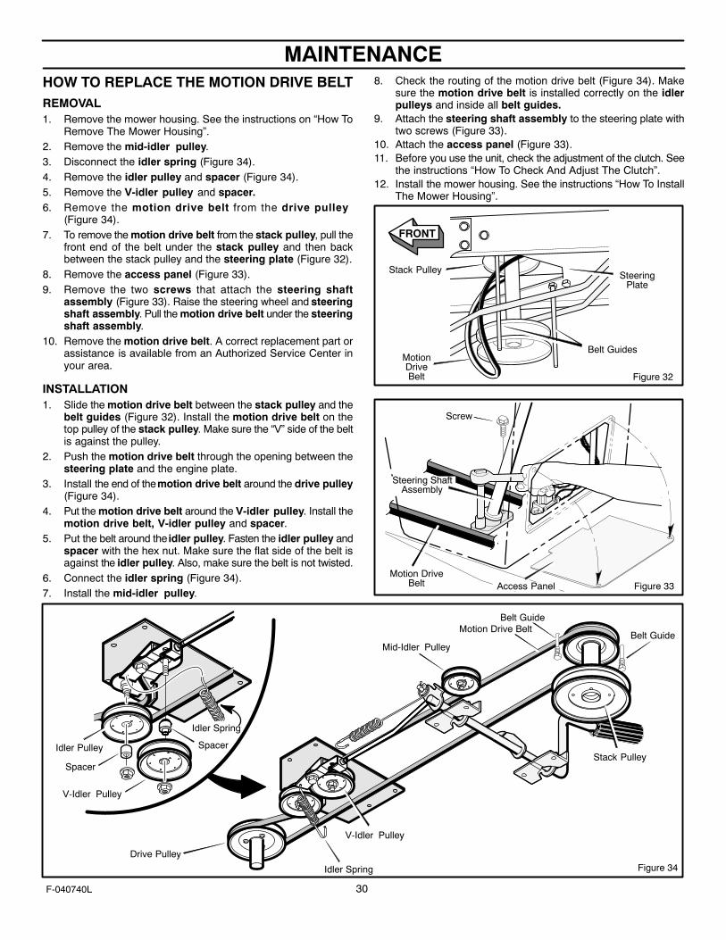
MAINTENANCE
30F-040740L
HOW TO REPLACE THE MOTION DRIVE BELTREMOVAL1. Remove the mower housing. See the instructions on “How To
Remove The Mower Housing”.2. Remove the mid-idler pulley.3. Disconnect the idler spring (Figure 34).4. Remove the idler pulley and spacer (Figure 34).5. Remove the V-idler pulley and spacer.6. Remove the motion drive belt from the drive pulley
(Figure 34).7. To remove the motion drive belt from the stack pulley, pull the
front end of the belt under the stack pulley and then backbetween the stack pulley and the steering plate (Figure 32).
8. Remove the access panel (Figure 33).9. Remove the two screws that attach the steering shaft
assembly (Figure 33). Raise the steering wheel and steeringshaft assembly. Pull the motion drive belt under the steeringshaft assembly.
10. Remove the motion drive belt. A correct replacement part orassistance is available from an Authorized Service Center inyour area.
INSTALLATION1. Slide the motion drive belt between the stack pulley and the
belt guides (Figure 32). Install the motion drive belt on thetop pulley of the stack pulley. Make sure the “V” side of the beltis against the pulley.
2. Push the motion drive belt through the opening between thesteering plate and the engine plate.
3. Install the end of the motion drive belt around the drive pulley(Figure 34).
4. Put the motion drive belt around the V-idler pulley. Install themotion drive belt, V-idler pulley and spacer.
5. Put the belt around the idler pulley. Fasten the idler pulley andspacer with the hex nut. Make sure the flat side of the belt isagainst the idler pulley. Also, make sure the belt is not twisted.
6. Connect the idler spring (Figure 34).7. Install the mid-idler pulley.
8. Check the routing of the motion drive belt (Figure 34). Makesure the motion drive belt is installed correctly on the idlerpulleys and inside all belt guides.
9. Attach the steering shaft assembly to the steering plate withtwo screws (Figure 33).
10. Attach the access panel (Figure 33).11. Before you use the unit, check the adjustment of the clutch. See
the instructions “How To Check And Adjust The Clutch”.12. Install the mower housing. See the instructions “How To Install
The Mower Housing”.
MotionDriveBelt Figure 32
FRONT
Stack PulleySteering
Plate
Belt Guides
Figure 33
Screw
Steering ShaftAssembly
Motion DriveBelt Access Panel
Stack Pulley
Motion Drive Belt
Drive PulleyFigure 34
Belt Guide
V-Idler Pulley
Idler Spring
Belt Guide
V-Idler Pulley
Idler Pulley Spacer
Idler Spring
Spacer
Mid-Idler Pulley
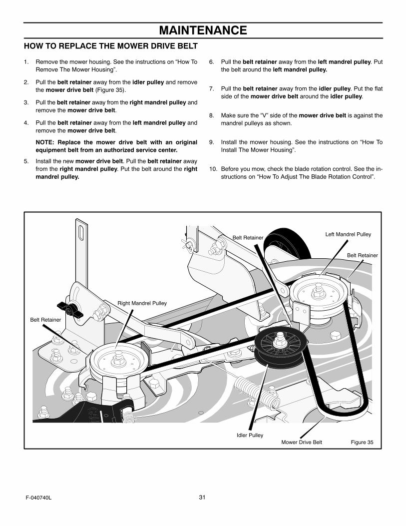
MAINTENANCE
31F-040740L
HOW TO REPLACE THE MOWER DRIVE BELT
1. Remove the mower housing. See the instructions on “How ToRemove The Mower Housing”.
2. Pull the belt retainer away from the idler pulley and removethe mower drive belt (Figure 35).
3. Pull the belt retainer away from the right mandrel pulley andremove the mower drive belt.
4. Pull the belt retainer away from the left mandrel pulley andremove the mower drive belt.
NOTE: Replace the mower drive belt with an originalequipment belt from an authorized service center.
5. Install the new mower drive belt. Pull the belt retainer awayfrom the right mandrel pulley. Put the belt around the rightmandrel pulley.
6. Pull the belt retainer away from the left mandrel pulley. Putthe belt around the left mandrel pulley.
7. Pull the belt retainer away from the idler pulley. Put the flatside of the mower drive belt around the idler pulley.
8. Make sure the “V” side of the mower drive belt is against themandrel pulleys as shown.
9. Install the mower housing. See the instructions on “How ToInstall The Mower Housing”.
10. Before you mow, check the blade rotation control. See the in-structions on “How To Adjust The Blade Rotation Control”.
Figure 35Mower Drive Belt
Belt Retainer
Right Mandrel Pulley
Belt RetainerLeft Mandrel Pulley
Idler Pulley
Belt Retainer
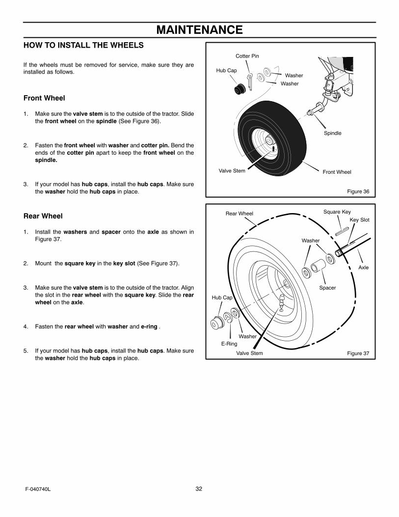
MAINTENANCE
32F-040740L
HOW TO INSTALL THE WHEELS
If the wheels must be removed for service, make sure they areinstalled as follows.
Front Wheel
1. Make sure the valve stem is to the outside of the tractor. Slidethe front wheel on the spindle (See Figure 36).
2. Fasten the front wheel with washer and cotter pin. Bend theends of the cotter pin apart to keep the front wheel on thespindle.
3. If your model has hub caps, install the hub caps. Make surethe washer hold the hub caps in place.
Rear Wheel
1. Install the washers and spacer onto the axle as shown inFigure 37.
2. Mount the square key in the key slot (See Figure 37).
3. Make sure the valve stem is to the outside of the tractor. Alignthe slot in the rear wheel with the square key. Slide the rearwheel on the axle.
4. Fasten the rear wheel with washer and e-ring .
5. If your model has hub caps, install the hub caps. Make surethe washer hold the hub caps in place.
Figure 36
Front Wheel
Spindle
Valve Stem
Washer
Washer
Hub Cap
Cotter Pin
Figure 37
E-RingWasher
Hub Cap
Washer
Spacer
Square Key
Valve Stem
Key Slot
Axle
Rear Wheel
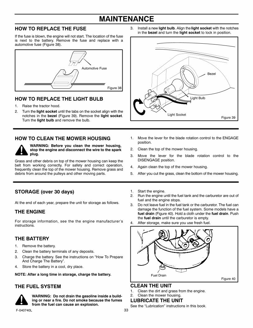
MAINTENANCE
33F-040740L
HOW TO REPLACE THE FUSEIf the fuse is blown, the engine will not start. The location of the fuseis next to the battery. Remove the fuse and replace with aautomotive fuse (Figure 38).
Figure 38
Automotive Fuse
HOW TO REPLACE THE LIGHT BULB1. Raise the tractor hood.
2. Turn the light socket until the tabs on the socket align with thenotches in the bezel (Figure 39). Remove the light socket.Turn the light bulb and remove the bulb.
3. Install a new light bulb. Align the light socket with the notchesin the bezel and turn the light socket to lock in position.
Bezel
Light Bulb
Light SocketFigure 39
HOW TO CLEAN THE MOWER HOUSINGWARNING: Before you clean the mower housing,stop the engine and disconnect the wire to the sparkplug.
Grass and other debris on top of the mower housing can keep thebelt from working correctly. For safety and correct operation,frequently clean the top of the mower housing. Remove grass anddebris from around the pulleys and other moving parts.
1. Move the lever for the blade rotation control to the ENGAGEposition.
2. Clean the top of the mower housing.
3. Move the lever for the blade rotation control to theDISENGAGE position.
4. Again clean the top of the mower housing.
5. After you cut the grass, clean the bottom of the mower housing.
STORAGE (over 30 days)
At the end of each year, prepare the unit for storage as follows.
THE ENGINE
For storage information, see the the engine manufacturer’sinstructions.
THE BATTERY1. Remove the battery.
2. Clean the battery terminals of any deposits.
3. Charge the battery. See the instructions on “How To PrepareAnd Charge The Battery”.
4. Store the battery in a cool, dry place.
NOTE: After a long time in storage, charge the battery.
THE FUEL SYSTEM
WARNING: Do not drain the gasoline inside a build-ing or near a fire. Do not smoke because the fumesfrom the fuel can cause an explosion.
1. Start the engine.2. Run the engine until the fuel tank and the carburetor are out of
fuel and the engine stops.3. Do not leave fuel in the fuel tank or the carburetor. The fuel can
damage the function of the fuel system. Some models have afuel drain (Figure 40). Hold a cloth under the fuel drain. Pushthe fuel drain until the carburetor is empty.
4. After storage, make sure you use fresh fuel.
Figure 40Fuel Drain
CLEAN THE UNIT1. Clean the dirt and grass from the engine.2. Clean the mower housing.
LUBRICATE THE UNITSee the “Lubrication” instructions in this book.
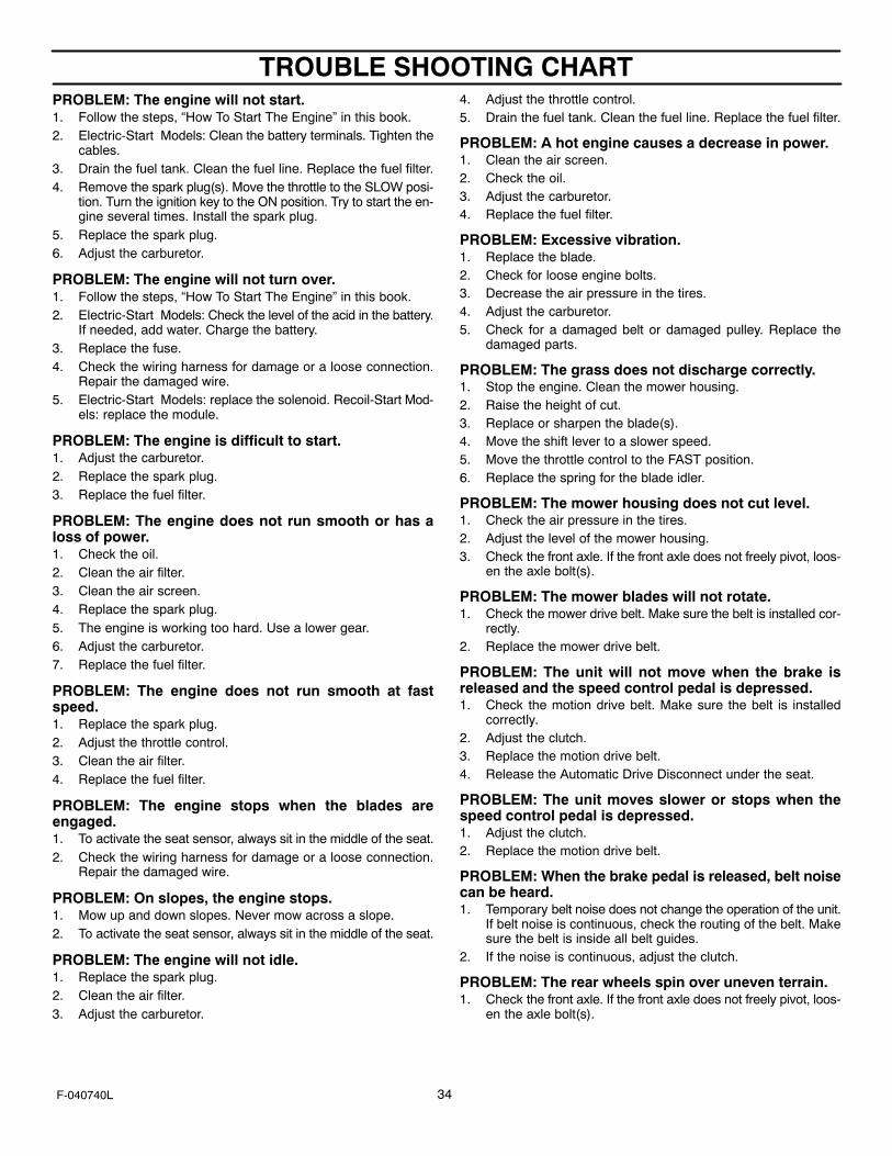
TROUBLE SHOOTING CHART
34F-040740L
PROBLEM: The engine will not start.1. Follow the steps, “How To Start The Engine” in this book.2. Electric-Start Models: Clean the battery terminals. Tighten the
cables.3. Drain the fuel tank. Clean the fuel line. Replace the fuel filter.4. Remove the spark plug(s). Move the throttle to the SLOW posi-
tion. Turn the ignition key to the ON position. Try to start the en-gine several times. Install the spark plug.
5. Replace the spark plug.6. Adjust the carburetor.
PROBLEM: The engine will not turn over.1. Follow the steps, “How To Start The Engine” in this book.2. Electric-Start Models: Check the level of the acid in the battery.
If needed, add water. Charge the battery.3. Replace the fuse.4. Check the wiring harness for damage or a loose connection.
Repair the damaged wire.5. Electric-Start Models: replace the solenoid. Recoil-Start Mod-
els: replace the module.
PROBLEM: The engine is difficult to start.1. Adjust the carburetor.2. Replace the spark plug.3. Replace the fuel filter.
PROBLEM: The engine does not run smooth or has aloss of power.1. Check the oil.2. Clean the air filter.3. Clean the air screen.4. Replace the spark plug.5. The engine is working too hard. Use a lower gear.6. Adjust the carburetor.7. Replace the fuel filter.
PROBLEM: The engine does not run smooth at fastspeed.1. Replace the spark plug.2. Adjust the throttle control.3. Clean the air filter.4. Replace the fuel filter.
PROBLEM: The engine stops when the blades areengaged.1. To activate the seat sensor, always sit in the middle of the seat.2. Check the wiring harness for damage or a loose connection.
Repair the damaged wire.
PROBLEM: On slopes, the engine stops.1. Mow up and down slopes. Never mow across a slope.2. To activate the seat sensor, always sit in the middle of the seat.
PROBLEM: The engine will not idle.1. Replace the spark plug.2. Clean the air filter.3. Adjust the carburetor.
4. Adjust the throttle control.5. Drain the fuel tank. Clean the fuel line. Replace the fuel filter.
PROBLEM: A hot engine causes a decrease in power.1. Clean the air screen.2. Check the oil.3. Adjust the carburetor.4. Replace the fuel filter.
PROBLEM: Excessive vibration.1. Replace the blade.2. Check for loose engine bolts.3. Decrease the air pressure in the tires.4. Adjust the carburetor.5. Check for a damaged belt or damaged pulley. Replace the
damaged parts.
PROBLEM: The grass does not discharge correctly.1. Stop the engine. Clean the mower housing.2. Raise the height of cut.3. Replace or sharpen the blade(s).4. Move the shift lever to a slower speed.5. Move the throttle control to the FAST position.6. Replace the spring for the blade idler.
PROBLEM: The mower housing does not cut level.1. Check the air pressure in the tires.2. Adjust the level of the mower housing.3. Check the front axle. If the front axle does not freely pivot, loos-
en the axle bolt(s).
PROBLEM: The mower blades will not rotate.1. Check the mower drive belt. Make sure the belt is installed cor-
rectly.2. Replace the mower drive belt.
PROBLEM: The unit will not move when the brake isreleased and the speed control pedal is depressed.1. Check the motion drive belt. Make sure the belt is installed
correctly.2. Adjust the clutch.3. Replace the motion drive belt.4. Release the Automatic Drive Disconnect under the seat.
PROBLEM: The unit moves slower or stops when thespeed control pedal is depressed.1. Adjust the clutch.2. Replace the motion drive belt.
PROBLEM: When the brake pedal is released, belt noisecan be heard.1. Temporary belt noise does not change the operation of the unit.
If belt noise is continuous, check the routing of the belt. Makesure the belt is inside all belt guides.
2. If the noise is continuous, adjust the clutch.
PROBLEM: The rear wheels spin over uneven terrain.1. Check the front axle. If the front axle does not freely pivot, loos-
en the axle bolt(s).
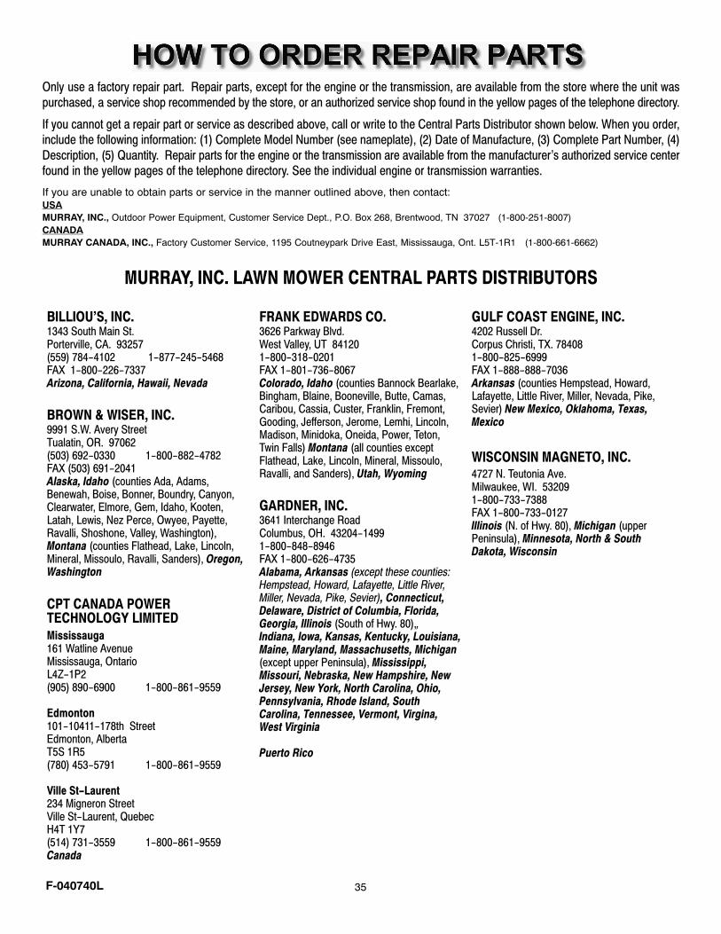
F-040740L 35
Only use a factory repair part. Repair parts, except for the engine or the transmission, are available from the store where the unit was
purchased, a service shop recommended by the store, or an authorized service shop found in the yellow pages of the telephone directory.
If you cannot get a repair part or service as described above, call or write to the Central Parts Distributor shown below. When you order,include the following information: (1) Complete Model Number (see nameplate), (2) Date of Manufacture, (3) Complete Part Number, (4)
Description, (5) Quantity. Repair parts for the engine or the transmission are available from the manufacturer’s authorized service centerfound in the yellow pages of the telephone directory. See the individual engine or transmission warranties.
If you are unable to obtain parts or service in the manner outlined above, then contact:USAMURRAY, INC., Outdoor Power Equipment, Customer Service Dept., P.O. Box 268, Brentwood, TN 37027 (1-800-251-8007)CANADAMURRAY CANADA, INC., Factory Customer Service, 1195 Coutneypark Drive East, Mississauga, Ont. L5T-1R1 (1-800-661-6662)
MURRAY, INC. LAWN MOWER CENTRAL PARTS DISTRIBUTORS
BILLIOU’S, INC.1343 South Main St.Porterville, CA. 93257(559) 784−4102 1−877−245−5468FAX 1−800−226−7337Arizona, California, Hawaii, Nevada
BROWN & WISER, INC.9991 S.W. Avery StreetTualatin, OR. 97062(503) 692−0330 1−800−882−4782FAX (503) 691−2041Alaska, Idaho (counties Ada, Adams,Benewah, Boise, Bonner, Boundry, Canyon,Clearwater, Elmore, Gem, Idaho, Kooten,Latah, Lewis, Nez Perce, Owyee, Payette,Ravalli, Shoshone, Valley, Washington),Montana (counties Flathead, Lake, Lincoln,Mineral, Missoulo, Ravalli, Sanders), Oregon,Washington
CPT CANADA POWER TECHNOLOGY LIMITEDMississauga161 Watline AvenueMississauga, Ontario L4Z−1P2(905) 890−6900 1−800−861−9559
Edmonton101−10411−178th StreetEdmonton, AlbertaT5S 1R5(780) 453−5791 1−800−861−9559
Ville St−Laurent234 Migneron StreetVille St−Laurent, QuebecH4T 1Y7(514) 731−3559 1−800−861−9559Canada
FRANK EDWARDS CO.3626 Parkway Blvd.West Valley, UT 841201−800−318−0201FAX 1−801−736−8067 Colorado, Idaho (counties Bannock Bearlake,Bingham, Blaine, Booneville, Butte, Camas,Caribou, Cassia, Custer, Franklin, Fremont,Gooding, Jefferson, Jerome, Lemhi, Lincoln,Madison, Minidoka, Oneida, Power, Teton,Twin Falls) Montana (all counties exceptFlathead, Lake, Lincoln, Mineral, Missoulo,Ravalli, and Sanders), Utah, Wyoming
GARDNER, INC.3641 Interchange Road Columbus, OH. 43204−14991−800−848−8946FAX 1−800−626−4735Alabama, Arkansas (except these counties:Hempstead, Howard, Lafayette, Little River,Miller, Nevada, Pike, Sevier), Connecticut,Delaware, District of Columbia, Florida,Georgia, Illinois (South of Hwy. 80),, Indiana, Iowa, Kansas, Kentucky, Louisiana,Maine, Maryland, Massachusetts, Michigan(except upper Peninsula), Mississippi, Missouri, Nebraska, New Hampshire, NewJersey, New York, North Carolina, Ohio,Pennsylvania, Rhode Island, SouthCarolina, Tennessee, Vermont, Virgina,West Virginia
Puerto Rico
GULF COAST ENGINE, INC.4202 Russell Dr.Corpus Christi, TX. 784081−800−825−6999FAX 1−888−888−7036 Arkansas (counties Hempstead, Howard,Lafayette, Little River, Miller, Nevada, Pike,Sevier) New Mexico, Oklahoma, Texas,Mexico
WISCONSIN MAGNETO, INC.4727 N. Teutonia Ave.Milwaukee, WI. 532091−800−733−7388FAX 1−800−733−0127Illinois (N. of Hwy. 80), Michigan (upperPeninsula), Minnesota, North & SouthDakota, Wisconsin
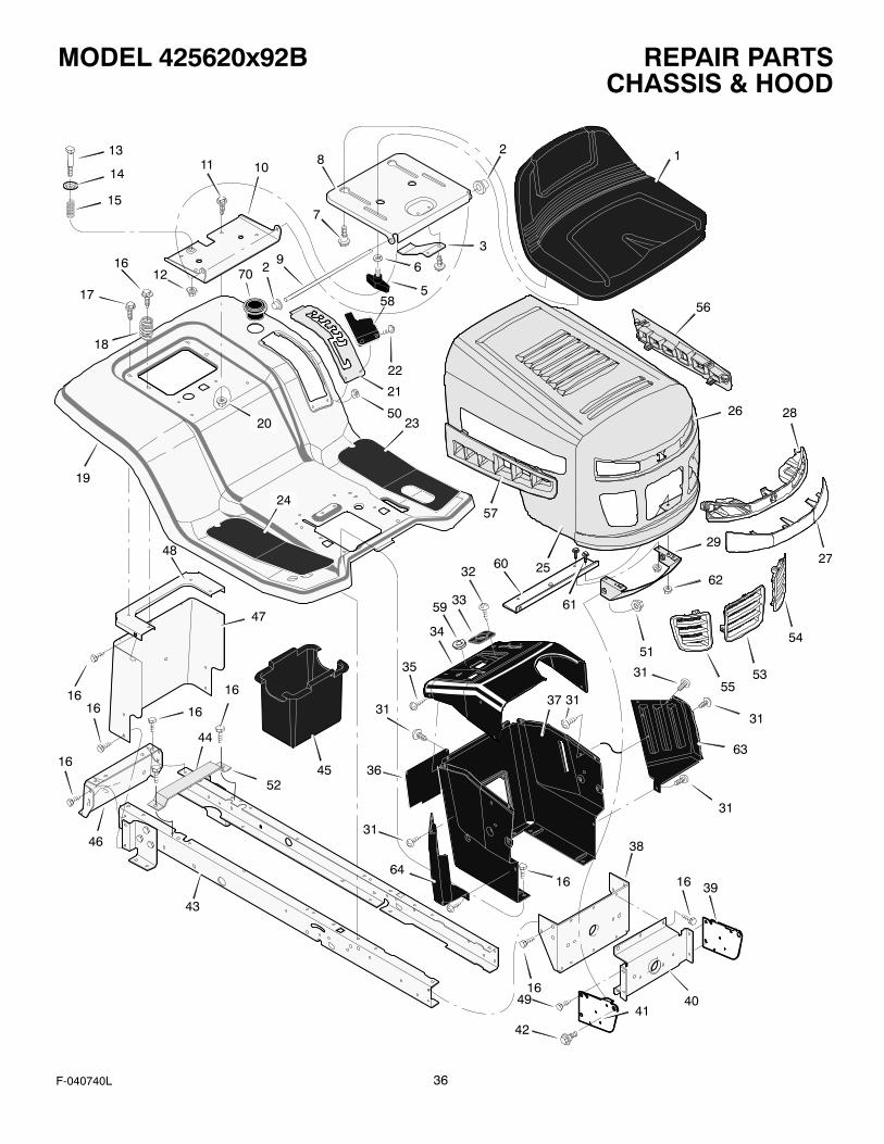
REPAIR PARTSMODEL 425620x92B
36F-040740L
CHASSIS & HOOD
43
44
46
16
1616
16
47
48
58
12
3
5
6
7
8
9
1011
12
13
14
15
16
17
18
19
20
24
21
22
23
32
33
34
35
31
36
37
38
16
4016
16
45
2
50
70
39
42
4941
16
52
59
56
26 28
27
54
5355
51
62
29
61
2560
57
31
31
31
31
31
63
64

REPAIR PARTSMODEL 425620x92B
37F-040740L
CHASSIS & HOOD
KeyNo. Part No. Description
KeyNo. Part No. Description
1 1001028 Seat
2 028x23 Cap, Push 0n
3 094057 Spring
4 26x229 Screw
5 1001054 Bolt, Wing
6 017x47 Washer
7 009x56 Bolt, Shoulder
8 094154E701 Support, Seat
9 094156 Z Rod, Pivot
10 1001648E700 Bracket, Pivot
11 001x45 Bolt
12 015x89 Nut
13 009x55 Bolt, Shoulder
14 094155 Z Washer
15 164x31 Spring
16 26x249 Screw
17 26x263 Screw
18 164x30 Spring
19 1001556E700 Deck, Seat
20 15x123 Nut
21 094194E701 Plate, Index
22 009x47 Screw
23 094383 Mat, Left
24 094382 Mat, Right
25 1001812E700 Hood
26 1001813E700 Grille
27 1001820 Lens
28 1001819 Housing, Light
29 1001799 Bracket, Lower Pivot
31 26x270 Screw
32 26x238 Screw
33 1001491 Bearing, Steering
34 1001594E700 Dash
35 26x201 Screw
36 093007E700 Panel, Access
37 095318E700 Support, Dash
38 1001270E701 Bracket, Rear Hanger
39 094085E700 Support, Left Grille
40 094007E701 Axle, Hanger
41 094084E700 Support, Right Grille
42 009x58 Bolt, Shoulder
43 1001268E701 Frame, Right
44 1001269E701 Frame, Left
45 690424 Container, Battery
46 1001002E701 Plate, Hitch
47 690218E700 Plate, Rear
48 094186E700 Top, Rear Plate
49 26x277 Screw
50 015x81 Nut
51 15x124 Nut
52 690482E701 Support, Battery
53 1001816 Insert, Center Grille
54 1001817 Insert, Left Grille
55 1001818 Insert, Right Grille
56 1001814 Insert, Left Hood
57 1001815 Insert, Right Hood
58 094680 Cover, Detent
59 1001755 Grommet, Parking Brake
60 1001921 Bracket, Support
61 0025x3 Screw
62 015x82 Nut
63 095218 Panel, Left Side
64 095217 Panel, Right Side
70 1001542 Holder, Cup
-- F-040740L Instruction Book & Parts List

REPAIR PARTSMODEL 425620x92B
38F-040740L
DRIVE ASSEMBLY1
1
1
1
1
1
2
45
6
7
8
9
9
10
11
12
14
15
16
17
18
21
222324
19
2019
2930
2827
2625
16
35
31
3332
34
3657
37
38
34
49
50
55 39
5639
40
42
41
46
43
4445
53
4741
48
52
51
40
53
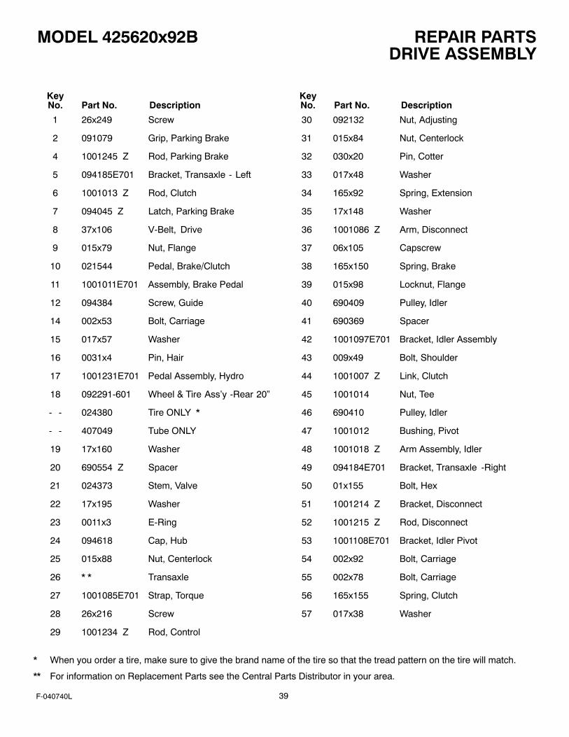
REPAIR PARTSMODEL 425620x92B
39F-040740L
DRIVE ASSEMBLY
KeyNo. Part No. Description
KeyNo. Part No. Description
1 26x249 Screw
2 091079 Grip, Parking Brake
4 1001245 Z Rod, Parking Brake
5 094185E701 Bracket, Transaxle - Left
6 1001013 Z Rod, Clutch
7 094045 Z Latch, Parking Brake
8 37x106 V-Belt, Drive
9 015x79 Nut, Flange
10 021544 Pedal, Brake/Clutch
11 1001011E701 Assembly, Brake Pedal
12 094384 Screw, Guide
14 002x53 Bolt, Carriage
15 017x57 Washer
16 0031x4 Pin, Hair
17 1001231E701 Pedal Assembly, Hydro
18 092291-601 Wheel & Tire Ass’y -Rear 20”
- - 024380 Tire ONLY *
- - 407049 Tube ONLY
19 17x160 Washer
20 690554 Z Spacer
21 024373 Stem, Valve
22 17x195 Washer
23 0011x3 E-Ring
24 094618 Cap, Hub
25 015x88 Nut, Centerlock
26 * * Transaxle
27 1001085E701 Strap, Torque
28 26x216 Screw
29 1001234 Z Rod, Control
30 092132 Nut, Adjusting
31 015x84 Nut, Centerlock
32 030x20 Pin, Cotter
33 017x48 Washer
34 165x92 Spring, Extension
35 17x148 Washer
36 1001086 Z Arm, Disconnect
37 06x105 Capscrew
38 165x150 Spring, Brake
39 015x98 Locknut, Flange
40 690409 Pulley, Idler
41 690369 Spacer
42 1001097E701 Bracket, Idler Assembly
43 009x49 Bolt, Shoulder
44 1001007 Z Link, Clutch
45 1001014 Nut, Tee
46 690410 Pulley, Idler
47 1001012 Bushing, Pivot
48 1001018 Z Arm Assembly, Idler
49 094184E701 Bracket, Transaxle -Right
50 01x155 Bolt, Hex
51 1001214 Z Bracket, Disconnect
52 1001215 Z Rod, Disconnect
53 1001108E701 Bracket, Idler Pivot
54 002x92 Bolt, Carriage
55 002x78 Bolt, Carriage
56 165x155 Spring, Clutch
57 017x38 Washer
* When you order a tire, make sure to give the brand name of the tire so that the tread pattern on the tire will match.
** For information on Replacement Parts see the Central Parts Distributor in your area.

REPAIR PARTSMODEL 425620x92B
40F-040740L
STEERING
1
2
3
4
5
6
7
8
9
10
11
12
15
6
13
30
30
30
17
18
3014
30
19
16
26
24
2122
23
25
27
24
25
22
23
28
29
2525
30
33
3536
19
31
31
3238
20
20
37
40
39

REPAIR PARTSMODEL 425620x92B
41F-040740L
STEERINGKeyNo.
PartNo. Description
1 094591 Wheel, Steering
2 690625 Post, Steering
3 094131 Clip, Retainer
4 094124 Bearing
5 15x111 Nut, Flange
6 009x57 Bolt, Shoulder
7 690183 Gear, Pinion
8 011x25 Ring, Snap
9 094121 Gear, Sector
10 094123 Bearing
11 001x84 Bolt
12 1001121E701 Plate, Steering
13 094006E701 Plate, Engine
14 015x88 Nut, Flange
15 15x118 Nut, Flange
16 1001270E701 Bracket, Hanger
17 094007E701 Axle, Hanger
18 01x146 Bolt
19 030x49 Pin, Cotter
20 690150 Bearing
21 094576E701 Spindle Assembly, Left
22 01x111 Bolt
23 17x104 Washer
24 017x53 Z Washer
25 015x84 Nut, Flange
26 1001460E701 Axle Assembly
27 095329E701 Drag Link, Left
28 094575E701 Spindle Assembly, Right
29 095328E701 Drag Link, Right
30 26x249 Screw
31 091334 Bearing, Wheel
32 024373 Stem, Valve
33 091912 Tire *
-- 407047 Tube
34 1001840-601 Wheel and Tire Assembly
35 17x195 Washer
36 17x192 Washer
37 17x113 Washer
38 094618 Hub Cap (Optional)
39 26x267 Screw
40 092059 Bellows
* When you order a tire, make sure to give the brand name of the tire so that the tread pattern on the tire will match.
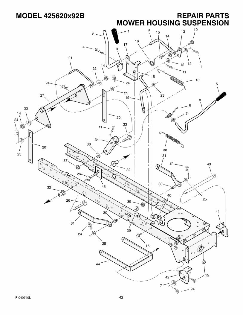
REPAIR PARTSMODEL 425620x92B
42F-040740L
MOWER HOUSING SUSPENSION1
2
34
5
6
7
8
14
14
9 10
111212
11
1314
15
1617
18
19
20
20
21
22
22
23
24 24
24
25
25
11
15
27
26
26
24
2515
33
3436
37
32
32
38
31
24
30
25
41
43
15
30
31
44
42
247
40
39
39
45

REPAIR PARTSMODEL 425620x92B
43F-040740L
MOWER HOUSING SUSPENSION
KeyNo. Part No. Description
KeyNo. Part No. Description
1 092698 Grip, PTO
2 094100 Z Handle, PTO
3 094022 Z Pad, Switch
4 0025x3 Bolt
5 092697 Grip, Lifter
6 166x40 Spring
7 17x103 Washer
8 690533 Lever, Lift
9 094017 Z Lever, PTO
10 009x39 Bolt, Shoulder
11 030x20 Pin, Cotter
12 017x57 Washer
13 094004 Z Link, PTO
14 015x84 Nut, Flange
15 26x249 Screw
16 166x39 Spring
17 094018E701 Bracket, PTO
18 165x119 Spring
19 690394E701 Crank, PTO
20 690212E701 Link, Lift
21 690122E701 Link, Lift Handle
22 17x168 Washer
23 017x57 Washer
24 0031x4 Pin, Hair
25 017x91 Z Washer
26 002x85 Bolt, Carriage
27 1001111E701 Lever Assembly, Lift
30 094067 Pin
31 094055E701 Bracket, Rear Suspension
32 690151 Spacer, Lifter
33 009x53 Bolt, Shoulder
34 094015E701 Bracket, Pivot
36 17x191 Washer
37 015x84 Nut, Flange
38 165x131 Spring
39 015x68 Nut, Flange
40 094005E700 Bracket, PTO
41 094027E701 Hanger, Left Deck
42 094026E701 Hanger, Right Deck
43 094158 Z Rod, Hanger
44 690539E701 Bracket, Suspension
45 1001098E701 Plate, Stiffening

REPAIR PARTSMODEL 425620x92B
44F-040740L
MOWER HOUSING
1
2
3 61
21
4
5
1110
47
13
7
1516
17
18
23
22
9
198
20
5
21
6
23
23
2412
27
25
24
2822
526
5
24
6
21
20
52
819
5
22
1110
1713
47
9
729
5
33
31
32
30
22
22
5
33
55
32
53
50 51
50
51
53
5433
33
32
544
42
42
3443
4136
37
38
39
40
38
39
40
37
35
36
14
345
33
33
59
45
32
17
22
46
17
48
15
22
57
58
60
60
49
5 23
62
17
22
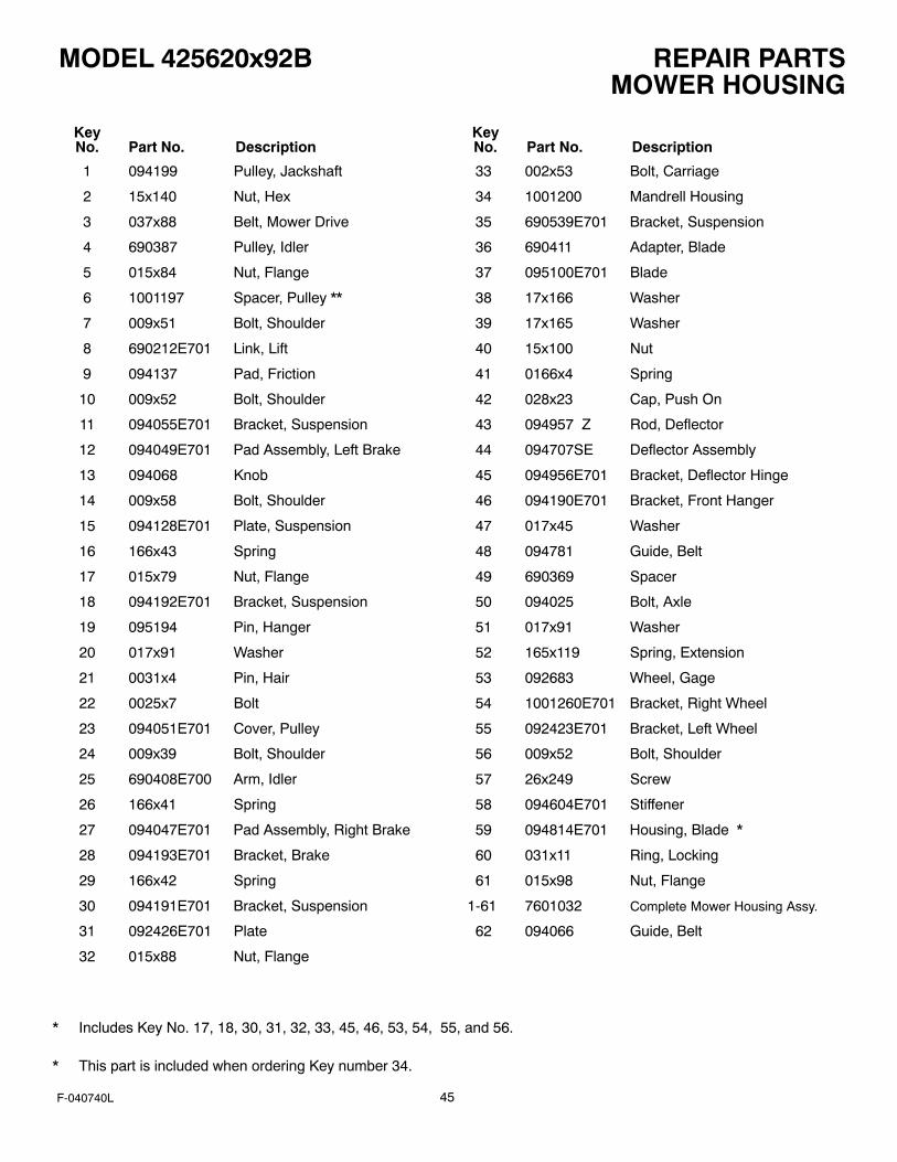
REPAIR PARTSMODEL 425620x92B
45F-040740L
MOWER HOUSING
KeyNo. Part No. Description
KeyNo. Part No. Description
1 094199 Pulley, Jackshaft
2 15x140 Nut, Hex
3 037x88 Belt, Mower Drive
4 690387 Pulley, Idler
5 015x84 Nut, Flange
6 1001197 Spacer, Pulley **
7 009x51 Bolt, Shoulder
8 690212E701 Link, Lift
9 094137 Pad, Friction
10 009x52 Bolt, Shoulder
11 094055E701 Bracket, Suspension
12 094049E701 Pad Assembly, Left Brake
13 094068 Knob
14 009x58 Bolt, Shoulder
15 094128E701 Plate, Suspension
16 166x43 Spring
17 015x79 Nut, Flange
18 094192E701 Bracket, Suspension
19 095194 Pin, Hanger
20 017x91 Washer
21 0031x4 Pin, Hair
22 0025x7 Bolt
23 094051E701 Cover, Pulley
24 009x39 Bolt, Shoulder
25 690408E700 Arm, Idler
26 166x41 Spring
27 094047E701 Pad Assembly, Right Brake
28 094193E701 Bracket, Brake
29 166x42 Spring
30 094191E701 Bracket, Suspension
31 092426E701 Plate
32 015x88 Nut, Flange
33 002x53 Bolt, Carriage
34 1001200 Mandrell Housing
35 690539E701 Bracket, Suspension
36 690411 Adapter, Blade
37 095100E701 Blade
38 17x166 Washer
39 17x165 Washer
40 15x100 Nut
41 0166x4 Spring
42 028x23 Cap, Push On
43 094957 Z Rod, Deflector
44 094707SE Deflector Assembly
45 094956E701 Bracket, Deflector Hinge
46 094190E701 Bracket, Front Hanger
47 017x45 Washer
48 094781 Guide, Belt
49 690369 Spacer
50 094025 Bolt, Axle
51 017x91 Washer
52 165x119 Spring, Extension
53 092683 Wheel, Gage
54 1001260E701 Bracket, Right Wheel
55 092423E701 Bracket, Left Wheel
56 009x52 Bolt, Shoulder
57 26x249 Screw
58 094604E701 Stiffener
59 094814E701 Housing, Blade *
60 031x11 Ring, Locking
61 015x98 Nut, Flange
1-61 7601032 Complete Mower Housing Assy.
62 094066 Guide, Belt
* Includes Key No. 17, 18, 30, 31, 32, 33, 45, 46, 53, 54, 55, and 56.
* This part is included when ordering Key number 34.

REPAIR PARTSMODEL 425620x92B
46F-040740L
ENGINE MOUNT1
6
7
8
9
10
11
1213
14
15
15
21
2222
21
2
3
45
26
30
31
9f
9a
9d
9b
9b
9c
23
23
9e
32

REPAIR PARTSMODEL 425620x92B
47F-040740L
ENGINE MOUNT
KeyNo. Part No. Description
1 092317 Fuel Cap **
2 094073 Fuel Tank
3 095197 Hose Clamp **
4 7601033 Fuel Line (Must cut to length) **
5 095197 Hose Clamp **
6 26x201 Screw
7 094006E700 Plate, Engine
8 092371 Throttle Control
9 * Engine, BRIGGS & STRATTON
9a 1001717 Muffler
9b 091309 Gasket, Muffler
9c 095207 Adapter, Muffler
9d 06x103 Screw, Adapter
9e 009x59 Bolt, Muffler
9f 092378 Lock, Screw
10 0025x7 Bolt, Engine Mount
11 690440 Z Stack Pulley Assembly
12 019x35 Lockwasher
13 01x140 Bolt, Hex
14 17x170 Washer
15 26x249 Screw
21 094384 Guide, Belt
22 015x79 Z Nut, Flange
23 094066 Guide, Belt
26 26x253 Screw
30 1001897 Shield, Heat
31 26x263 Screw
32 06x104 Screw
* For information on Replacement Parts for this engine contact the manufacturer.
* * These parts are included with Key number 2.
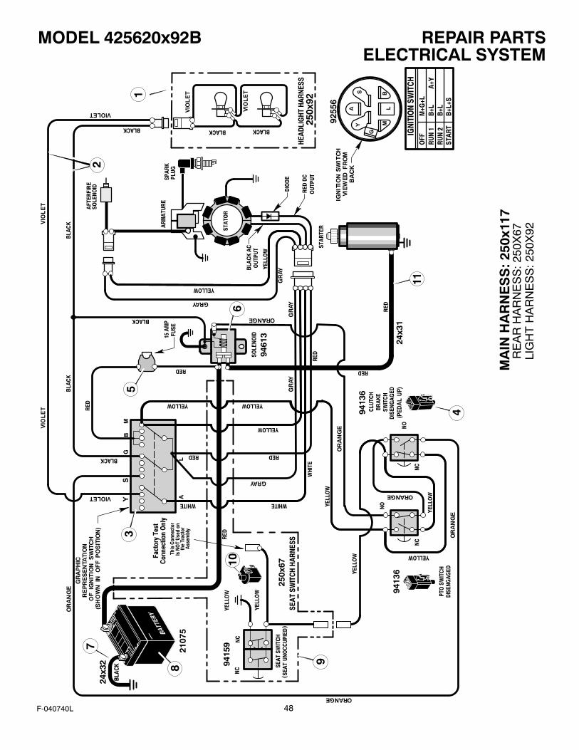
REPAIR PARTSMODEL 425620x92B
48F-040740L
ELECTRICAL SYSTEM
24x3
2 9415
9
24x3
1
9255
6
9461
3
2107
5
9413
6
9413
6
MA
IN H
AR
NE
SS
: 25
0x11
7R
EA
R H
AR
NE
SS
: 250
X67
LIG
HT
HA
RN
ES
S: 2
50X
92
13
4
5
6
8 9
7
10
11
2

REPAIR PARTSMODEL 425620x92B
49F-040740L
ELECTRICAL SYSTEM
KeyNo. Part No. Description
1 250x92 Harness, Light Wire
1001716 Socket, Light
090084 Bulb, Light
2 250x117 Harness, Chassis Wire
3 092556 Switch, Ignition
020729 Key, Ignition
091489 Nut, Hex
091488 Cap, Ignition
4 094136 Switch, Limit
5 302031 Fuse
407078 Holder, Fuse
6 094613 Solenoid
26x229 Screw, Mounting
15x116 Locknut
7 024x32 Cable, Battery Ground
26x213 Screw, Ground Cable
8 021075 Battery
002x82 Bolt, Carriage
014x79 Wingnut
9 250x67 Harness, Seat Switch Wire
10 094159 Switch, Seat Sensor
11 024x31 Cable

50F-040740L

INDEX
51F-040740L
AAdjustments
Blade Rotation Control, 23Clutch, 24Drive Brake, 25Mower Housing, Level, 29
Attachments, 15, 52Automatic Drive Disconnect,
Operation, 16
BBattery
Charge, 25Check, 12Clean, 25Install, 12Removal, 25Storage, 33
BeltMotion Drive
Adjust, 24Replace, 30
Mower DriveAdjust, 23Replace, 31
BladeInspect, 22Remove And Install, 22Sharpen, 22
Blade Rotation ControlAdjust, 23Location, 14Operation, 15
Brake Pedal, Location, 14
CClutch
Adjust, 24Check, 24
Controls, Location, 14Cutting Height
Adjust, 29Change, 17
DDrive Brake
Adjust, 25Check, 25
EEngine
Fuel, 13, 19Oil, 13, 19Preparation, 13Spark Arrester, 13, 21Starting, 19Storage, 33
Throttle Control, 15
FFilter, Fuel, 26Fuel, Type, 19Fuse, 33
HHeadlight, Replace Light Bulb, 33Headlight Switch, Location, 14
IIgnition Switch, Location, 14
LLift Lever
Location, 14Operation, 17
Lubrication, Mower, 26
MMaintenance
Adjust, Guage Wheels, 28Battery
Charge, 25Clean, 25
BeltMotion Drive, 30Mower Drive, 31
Blade, 22Blade Rotation Control, 23Clutch, 24Drive Brake, 25Filter, Fuel, 26Fuse, 33Headlight, 33Install, Wheels, 32Lubrication, 26Mower Housing
Clean, 33Install, 27Level, 29Remove, 27
Muffler, 21Storage, 33
Maintenance Chart, 21Motion Drive Belt
Adjust, 24Replace, 30
Mower Drive BeltAdjust, 23Replace, 31
Mower HousingClean, 33Cutting Height, 17Install, 27Level Adjustment, 29Operation, 18
Remove, 27Muffler, 21
Spark Arrester, 21
OOil
Check, 19Type, 19
OperationAttachments, 15Automatic Drive Disconnect, 16Blade Rotation Control, 14, 15Brake Pedal, 14Headlight Switch, 14Ignition Switch, 14Lift Lever, 14, 17Location Of Controls, 14Mower Housing, 18Mowing And Bagging, 20Operate On Hills, 18Parking Brake, 14, 17Speed Control Pedal, 14, 16Start The Engine, 19Stop The Unit, 17Throttle Control, 14, 15Transport, 17
PParking Brake
Location, 14Operation, 17
Parts Bag, 10
SSafety Rules
American National Standard Institute,3–4
Safe Mowing Guide, 5–7Seat, Install, 11Seat Switch, Operation, 19Slope Guide, 50Spark Arrester, 13, 21Speed Control Pedal
Location, 14Operation, 16
Steering Wheel, 11Storage, 33
TThrottle Control
Location, 14Operation, 15
Tire Pressure, 13, 26Trouble Shooting Chart, 34
WWarranty, 2
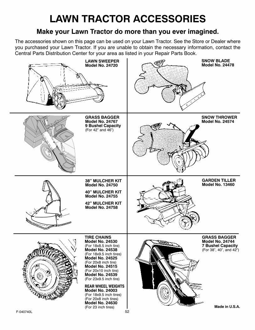
52F-040740L
LAWN TRACTOR ACCESSORIESMake your Lawn Tractor do more than you ever imagined.
The accessories shown on this page can be used on your Lawn Tractor. See the Store or Dealer whereyou purchased your Lawn Tractor. If you are unable to obtain the necessary information, contact theCentral Parts Distribution Center for your area as listed in your Repair Parts Book.
ÎÎ
LAWN SWEEPERModel No. 24720
SNOW BLADEModel No. 24478
SNOW THROWERModel No. 24574
Made in U.S.A.
38” MULCHER KITModel No. 24750
40” MULCHER KITModel No. 24755
42” MULCHER KITModel No. 24758
TIRE CHAINSModel No. 24530(For 18x8.5 inch tire)Model No. 24538(For 18x9.5 inch tires)Model No. 24525(For 20x8 inch tire)Model No. 24515(For 20x10 inch tire)Model No. 24539(For 23x9.5 inch tire)
GRASS BAGGERModel No. 247679 Bushel Capacity(For 42” and 46”)
REAR WHEEL WEIGHTSModel No. 24003(For 18x9.5 inch tires)(For 20x8 inch tires)Model No. 24630(For 23 inch tires)
GARDEN TILLERModel No. 13460
GRASS BAGGERModel No. 247447 Bushel Capacity(For 38”, 40”, and 42”)


![CATALOG MOTOUNELTE SI ACCESORII 2016-2017hitachi-powertools.ro/CATALOG_GRADINA.pdf · Unelte pentru Gradinarit 42 IGlobal Network 46 A] A 25EB(N) 18 [CG] 10 10 9 CG 22EAB(L) 9 CG](https://static.fdocuments.net/doc/165x107/5b02f81d7f8b9ab9598e9bea/catalog-motounelte-si-accesorii-2016-2017hitachi-pentru-gradinarit-42-iglobal-network.jpg)