Muncie PTO FA Series Installation & Owner's Manual · PTO INSTALLATION & OWNER'S MANUAL ---Muncie...
24
PTO INSTALLATION & OWNER'S MANUAL --- Muncie Power Products, Inc. --- FOR MUNCIE FA SERIES PTO USED ON THE FORD 4R100 AUTOMATIC TRANSMISSION For Muncie PTO parts or service call Pro Gear & Transmission, Inc. 877-776-4600 I 407-872-1901 I [email protected]
Transcript of Muncie PTO FA Series Installation & Owner's Manual · PTO INSTALLATION & OWNER'S MANUAL ---Muncie...

PTO INSTALLATION
& OWNER'S MANUAL
--- Muncie Power Products, Inc. ---
FOR MUNCIE FA SERIES PTO USED ON THE FORD 4R100AUTOMATIC TRANSMISSION
For Muncie PTO parts or service call Pro Gear & Transmission, Inc. 877-776-4600 I 407-872-1901 I [email protected]

PTO INSTALLATION & OWNER'S MANUAL
FOR MUNCIE FA SERIES PTO USED ON THE FORD 4R100 AUTOMATIC TRANSMISSION
TABLE OF CONTENTS Section 1 - PTO Installation PTO Installation Instructions ..................................................................................... 1.1
Section 2 - Activation Installation FA Series Electric/Hydraulic Shift System ................................................................. 2.1 PTO Instructions & Tests ........................................................................................... 2.2
Section 3 - Owner's Manual Power Take-Off Warranty .......................................................................................... 3.1 PTO Shifting Procedure & Precautions ..................................................................... 3.2 PTO Maintenance ...................................................................................................... 3.3 PTO Torque & Horsepower Ratings .......................................................................... 3.3 PTO Troubleshooting Guide ......................................................................... back cover
A WARNING READ MANUAL COMPLETELY INCLUDING THESE WARNINGS AND OPERATOR'S INSTRUCTIONS IN SECTION 3
• READ AND UNDERSTAND ENTIRE MANUAL BEFORE INSTALLATION OR OPERATION OF PTO AND DRIVEN EQUIPMENT
• ALWAYS DISENGAGE THE PTO WHEN THE DRIVEN EQUIPMENT IS NOT IN OPERATION.
• DO NOT ATTEMPT TO INSTALL OR SERVICE ANY POWER TAKE-OFF WITH THE TRUCK ENGINE RUNNING. TURN OFF ENGINE AND PUT THE IGNITION KEYS IN YOUR POCKET BEFORE GETTING UNDER THE TRUCK.
• DO NOT ALLOW TRUCK ENGINE TO BE STARTED WHILE WORKERS ARE UNDER THE TRUCK.
• IMMOBILIZE TRUCK WHEELS WITH SUITABLE CHOCKS BEFORE WORKING UNDER TRUCK.
• BE SURE TO BLOCK ANY RAISED BODY OR MECHANISM BEFORE WORKING ON OR UNDER THE EQUIPMENT.
• INSTALLED POWER TAKE-OFFS MUST NEVER BE SHIFTED IN OR OUT OF GEAR BY ANY MEANS EXCEPT BY THE CONTROLS IN THE CAB OF THE TRUCK.
• STAY CLEAR OF SPINNING DRIVESHAFTS TO AVOID BECOMING ENTANGLED AND INJURED.
• IT SHALL BE THE RESPONSIBILITY OF THE INSTALLER OF A MUNCIE POWER TAKE-OFF TO DECIDE WHETHER TO INSTALL GUARDS IN THE PTO AND/OR DRIVELINE AREA BECAUSE OF POTENTIAL EXPOSURE TO DANGER.
THIS IS BECAUSE MOST MUNCIE PTOS ARE INSTALLED BY EQUIPMENT DISTRIBUTORS OR MANUFACTURERS AND THEREFORE, THE RESPONSIBILITY OF THE INSTALLATION IS BEYOND THE CONTROL OF MUNCIE POWER PRODUCTS.
• OBTAIN PROPER TRAINING BEFORE OPERATING THIS MACHINERY DO NOT INSTALL OR OPERATE EQUIPMENT WHICH HAS NOT BEEN PROPERLY SPECIFIED FOR YOUR EQUIPMENT.
• ALLOW THE VEHICLE, PTO AND DRIVEN EQUIPMENT TO WARM UP WHEN OPERATING IN WEATHER WHERE TEMPERATURES ARE NEAR OR BELOW FREEZING 32 °F (0 °C).
• INSTALL SEPARATE CONTROLS FOR PTO AND DRIVEN EQUIPMENT.
• ALWAYS INSTALL THE SAFETY LABELS PROVIDED AND PLACE THE OWNER'S MANUAL IN THE VEHICLE GLOVE COMPARTMENT.
The PTO is supplied with a packet containing warning labels. If you did not receive any, or if you need extra, you may order them, no charge, by phone, email, or mail. They are available through your nearest Muncie distributor or at the number below: A This symbol warns of personal injury. 1-800-FOR-PTOS (367-7867)
email: [email protected] © Muncie Power Products, Inc. 2010

SECTION 1 PTO INSTALLATION
ALL INSTALLERS MUST READ THE FOLLOWING
PTO AND ACTIVATION KIT INSTALLATION INSTRUCTIONS
Always wear safety glasses. Read entire manual before starting installation.
IMPORTANT: Disconnect vehicle battery prior to installing electrical and electric/hydraulic activation kits.
A. Vehicle manufacturers may have specific locations for the accessing of electrical power and activation hydraulics. The body builder manual or company representative for the vehicle chassis should be contacted prior to installing electrical or hydraulic systems.
B. Route wires and activation lines away from rotating and high temperature components. Use appropriate looms and bulk head pass-thrus wherever possible to avoid rubbing through insulation or tubing and causing an electrical short or oil leak.
C. Follow all Federal Motor Vehicle Safety Standards (FMVSS) for your vehicle.
D. Where electrical grounds are indicated, be sure that they are good grounds, with straight paths to the vehicle battery ground. (Many vehicle cabs are insulated from the vehicle frame and a weak ground is a very common cause for malfunctions).
E. When installing hydraulic components, be certain to follow common installation and testing procedures. If you are not familiar with acceptable installation procedures request instructions and guidance from the hydraulic equipment supplier.
IMPORTANT INFORMATION: There is valuable information contained in the Ford "Super Duty F-Series Body Builders Layout Book". You can obtain a copy of this book by faxing your request to "Body Builder Coordinator" at 1-734-414-2971. Include your street address and desired vehicle and model
year. You can speak directly with the Ford Truck Body Builder Advisory Service at 1-877-840-4338.
PTO INSTALLATION INSTRUCTIONS
Always wear safety glasses. Read entire manual before starting installation.
1 ■ There is a packet with the PTO which contains 4 WARNING LABELS. Before adhering the labels, make sure the surfaces are free of dirt and grease. Place the labels supplied as follows:
There are two (2) labels which measure approximately 4" x 8" which are to be placed on the outside of the vehicle frame rail, making them easy to be seen by anyone who might go under the truck or near the PTO. One label is to be placed on each side of the vehicle.
1.1
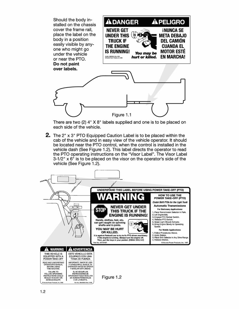
Should the body installed on the chassis cover the frame rail, place the label on the body in a position easily visible by anyone who might go under the vehicle
ADANGER APELIGRO
or near the PTO.
NEVER GET ~ i NUNCA SE UNDER THIS ([>,- META DEBAJO
TRUCK IF .0:-'.... DEL CAMION THE ENGINE CUANDA EL IS RUNNING! You may be MOTOR ESTE :,,.:.=..=..-:... hutt or killed. EN MARCHAi
Do not paint over labels.
Figure 1.1
There are two (2) 4" X 8" labels supplied and one is to be placed on each side of the vehicle.
2. The 2" x 3" PTO Equipped Caution Label is to be placed within the cab of the vehicle and in easy view of the vehicle operator. It should be located near the PTO control, when the control is installed in the vehicle dash (See Figure 1.2). This label directs the operator to read the PTO operating instructions on the "Visor Label". The Visor Label 3-1/2" x 6" is to be placed on the visor on the operator's side of the vehicle (See Figure 1.2).
[
NEVER GET UNDER THIS TRUCK IF THE
ENGINE IS RUNNING! Hands, clothes, hair, etc, ~ ... ~, ...
can get caught on spinning :.--: ·· shafts and U-Jolnts. ~
YOU MAY BE HURT -.,....,r,. {"' OR KILLED.
It Is against Federal Law to try to fix PTO driwn machinery If the engine Is N nnlng. Always tum the engine off. Thon, putU,o keys In ~rpockot. (OSHA 1910,147]
Part Na. 36T37607
Clutch Shill l'TOs far the Light Truck Automatic Transmissions
For Stetlonary Appllcations:
1. Place Transmission Selector In Par1<. 2. let Engine Idle. 3. Engage PTO Rocker Switch. 4. A- PTO Switch. 5. Green light Shook! Activate. 6. Bring Engine Slowly to Operating
Speed.
For Mobi .. Applications:
1. Follow Procodures Ab<Ne. 2. Apply Brakes. 3. Place Shift Selector In Ht/ DriYe Range. 4. Release Brakes.
C Muncil, Poww Product•, Irle. 199'1
THIS VEHICLE IS ESTE VEHICULO ESTA EQUIPPED WITH A EQUIPADO CON UNA POWER TAKE-OFF TOMA DE FUERZA
READ ANO UNDERSTAND OPERATOR"$ MANUAL
BEFORE USING 11-ilS MACHINE.
FAILURE TO FOU.OW OPERATING
INsmJCTIONS COULD RESULT IN OEATH OR
SEFUOUS INLURV, o,..,,,_.._AoOllck. li!,Q,, 20JI
1.2
IMPORTANTE. FAVOR DE LEER Y CONSULT AR EL MANUAL OE
OPEAACION NmS OE OPE.AAR Y MANE.JAR ESTA UNIOAO.
EL NOSEGIJIRLAS INSTR\JCCIONES OE
OPEAAQON PUEOA RESULTAA EN HERIOAS PERSONALES
OENLAMUEATE.. Pw'IHo.~!Q ...... 'f,08]
Figure 1.2

3. Run transmission in neutral. Determine sound of transmission before the PTO is installed. A noise in the transmission gear may be more noticeable after PTO is installed. Stop engine.
4. Do not drain transmission fluid, but be prepared for a small amount of oil to escape from opening. Avoid contact with this oil because it may be HOT. Remove cover plate. Remove cover gasket and set it aside for reuse when mounting PTO. Do Not discard the gasket. It must be used to install the PTO. Clean mounting pad. Inspect bolt holes in aperture for thread sealant used on OEM bolts. Clean these internal threads with wire brush to clear any material, if found.
5. Check transmission for proper PTO driver gear and location. Check PTO driver gear for condition. A nick or blemish may cause excessive noise when PTO is mounted.
6. Installation of the PTO is made easier if the transmission shifter linkage is disconnected and the cable bracket is temporarily removed. This is the large black bracket located directly rearward of the PTO opening. Be sure to retain these components for re-installation after the PTO is installed.
7. Remove the activation kit components from the PTO carton. Included in this kit is a 90° street elbow. This elbow does not have an orifice.
8. Install the elbow into the main pressure port located directly below the PTO opening. Install this elbow as far as it will go while positioning the port towards the rear of the vehicle (Fig 2).
9. Install the hose assembly with the 1/8" male pipe end into the elbow.
10. Route the hose assembly to lear interference with the transmission or its components.
1/8'-27 NPT Pressure Tap (120-130 psi w/PTO actvated)
Cover Plate
Fig 2
Fig 3
1.3

11. When installing the Muncie hydraulic pump on the Gas 4x4 application the pump will interfere with the H.E.G.0. sensor installed by Ford. You will need to remove th is sensor to have clearance to mount the Pump. After the PTO and pump are installed the H.E.G.O. sensor must be re- installed (Fig 4b). When replacing the H.E.G.O., a new "crush" washer should be used. This washer is included with the small parts package shipped with the PTO (PN 13T37626).
4X2 Applica1ions with Direet Mount Pump
Fl 4a
4x4 AppllcilliOJIS llirecl t,,ount Pump Only
0 (HEGO) Senso1 GAS Exhaust Only
f ig 4b
12. Locate the stud kit provided with the PTO. The FA62 PTO is provided with 4 capscrews and 2 special studs. The FA64 (4x4) PTO is provided with 2 capscrnws and 4 studs. One stud is a 3/8-24 UNF to 10mm PTO stud. This stud should be installed into the upper left hole location as shown (Fig Sb). One of the other studs is a special 5/16-18 UNG to 10mm step stud. The step stud is to be installed into the bottom center hole as shown (Fig Sb). The other 2 studs are special alignment studs. The alignment studs are included in both the FA62 and the FA64 stud kits. These studs are identified by the larger barrel in the middle of the stud and they are plated a blue color. These alignment studs must be inserted into the correct hole locations as shown in Fig Sa and Sb.
Note: The alignment studs replace the hollow dowel pins used in previous versions of the FA. If your PTO has the hollow dowel pins inserted in the housing, remove them and use only the alignment studs.
13. Place the transmission gasket which was removed in Step 4, over the alignment studs making sure that the larger holes in the gaskeVshim are located directly over the alignment studs installed in step 12. Place the PTO on to the transmission opening. Make sure the gasket is f lat against the transmission (Fig 5a,b).
14. Step 15 is divided into separate instructions for the 4x4, FA64 series PTO and the 4x2 FA62 series PTO. Read carefully before making the installation. It is important to check for gaps between the PTO and transmission and make sure gear teeth are properly meshed before tightening nuts, regardless of which PTO model you are installing.
1.4

15a. FA62 (Fig 5a) - Place the PTO into position on the transmission apertu re using the alignment studs as guides. Hold the PTO in position and insert the top and bottom 10mm capscrews to hold the PTO while the remaining capscrews are installed (Fig 5a). Install hex nuts on the two remaining studs. Tighten the capscrews to approximately 30 ft.lbs. Tighten the nuts to 35-40 ft.lbs.
15b. FA64 (Fig 5b,5c) - Place the PTO into position over the installed studs. Install the 3/8" hex nut on to the stud, but turn the nut only 4 turns. This will keep the PTO in place so that the bottom lock nut can be installed. Lift the lower portion of the PTO away from the pad and install the 5/16 11 lock nut to the bottom center stud (Fig Sc). Work the nut flush with the housing making sure that the gasket is in position while turning the nut. Tighten the upper left nut so that it is flush with the housing. Install the remain ing 2 capscrews and tighten to approxlmately 30 ft.lbs. Install the 3/8 11 hex nuts on the two remaining studs. Tighten all of the 3/8" hex nuts to 35-40 ft.lbs and tighten the 5/16" lock nut to approximately 17 ft.lbs.
16. Checking the backlash is not required when using the approved Ford furnished gasket. Should the gasket be damaged, obtain a Ford original equipment replacement. The Muncie part number for this gasket is 13T37386 (Not included with the PTO.) NOTE: Never use silicone type sealant on PTO/transmission mounting surface as proper backlash cannot be attained.
17. Approximating the torque would be required for capscrew loca-
4x2 Installation - FA62
Fig 5a
4x4 Installation - FA64
Fig 5b
/1. 1Qn en 'f' Stud Location
~
Afignment Sud location :
T , / N~~~~ I ."" Stud Partially
tions where a torque wrench can Ag 5c not be applied. This can be accomplished by the installer com-paring the tightness of an accessible capscrew. Tighten this with the wrench to be used on the hard-to-reach capscrew. Check the torque. Repeat until the installer "gets the feel" of this torque. Then tighten the hard-to-reach capscrew so that it approximates this torque.
1.5

18a. Locate the solenoid manifold and remove protective cap plugs. Install the (3) straight thread fittings into the ports as shown inf:Figure 6.
18b. In the port labeled "IN", install the JIC tee fitting. In the ports marked "CL" (clutch activation) and "EXH" exhaust), install JIC elbow fittings.
19. Install the pressure switch into the block using pipe thread sealant (port marked "PS".) Figure 6
20a. Install the special orifice fitting (43T37385) into the port located in the bottom of the main PTO housing. NOTE: The orifice fitting is plated "silver", bagged,
1.6
and labeled to identify it as the orifice fitting. Instal l the pipe thread hose end from the lube line into this fitting. Figure 7
1-4 Str. Thread to JIC I
Figure 6
Pipe Thread Hose End
Figure 7

20b. Connect the main pressure hose to the tee fitting at the "IN" port on the block. Connect the lubrica-tion hose to the other side of the tee fitting. Figure 8
21. Remove the cap plugs from the closed end cover on the PTO. Install the Figure 8 straight thread fit-ting into the port which is pointed towards the ground. Install the pipe thread fitting into the port located on the end of the cover. Figure 9a
A EXH Port (1/8" NPT)
B Pressure Port
(-4 Str. Thread)
Figure 9a
22. Locate the hose which has a JIC swivel hose end on both ends of the line. Connect one end to the pressure port on the PTO (the one with the straight thread fitting) and connect the other end to the "CL" port on the solenoid block. Figure 9b
Figure 9b (EXH)
Attach with -4 JIC Elbow
23. Locate the remaining hose which also has two JIC swivel hose ends. Connect one end to the "EXH" port on the sole
Figure 9c
noid block. The other end can be connected to a 90 degree JIC to JIC fitting supplied with the kit and then connect to the fitting in the end cover. Figure 9c
1.7

24. Find a suitable location forward and above the PTO opening to install the activation solenoid.
25. The solenoid is provided with mounting hardware. A small bracket may be fabricated to attach to an existing hole on the transmission
26. Use cable ties to make sure hoses are routed away from the exhaust and away from any rotating components.
27a. Route the wiring harness from the vehicle front passenger compartment to the solenoid valve. Figure 1 O
Wire Harness from Vehicle Cab Figure 10
27b. The solenoid connector is a Weather-Pack type. The pressure switch connector is a Metri-Pack type. Figure 11a
27c. Make the connections to the pressure switch and to the solenoid valve. Figure 11b
1.8
Figure 11 a
Figure 11 b

28. The wire harness separates at a 4 wire connector. The connector is designed to fit through the 5/8" grommet provided. Separate the harness and feed the harness end through the grommet in the passenger barrier. Figure 11d
Feed this side through Grommet and through wall
in engine compartment Figure11d
29. Located at the 4 wire connector is a ground lead. Route this lead directly to the battery or battery terminal and ground this terminal.
30. When routing the wire harness be sure to tie the harness away from heat sources (Exhaust, Manifold, etc.) and away from rotating components (Driveshafts, Belts, etc.).
31. Remove the access panel located below the steering wheel.
32. Locate the 4 wire connector which was fed through the passenger barrier and connect this connector to the interior half of the PTO harness.
For FA Series PTO with optional "Z" shift option go to page 1.14.
For FA Series PTO with optional Ford "APCM" control go to page 1.14.
For FA Series PTO with optional "SPD-1001A,, System Protection Device, go to page 1.15.
1.9

33. The connection for the FA Series PTO is important. The PTO connections are found behind the access panel located below the steering
34.
1.10
wheel.
The PTO wires are taped together and are labeled "Power Take Off Circuit."
Find the "Data Link Connector" lo- Remove Panel cated below the access panel and follow the wire up behind the panel.
Care must be taken because Ford also provides 4 "Customer Pass Through Circuits" for connection of auxiliary body builder's circuits.
The Two PTO Circuit wires are located below the "Pass Through" wires.
Be sure to look carefully at the wires before connecting them. Ford changed the color code after Job1 . The wire which provides 12V is White with a Blue stripe (2002 & Later) [Light Blue with a Pink Stripe(1999-2001), and originally Red with a Yellow stripe. (1998)). The other wire is Light Blue with a Yellow stripe. This wire connects to
Locate PTO Circuit Wire
Locate Plug at Bottom of Panel
Follow Data Link Connector Wire
the Muncie "Blue w/Yellow". These Body Builder Pass-Through PTO Circuit
wires have been shortened by Ford and you will need to follow the data link bundle up to the joint with the main cable. Pull the joint apart to find the correct wires.
If you fail to connect this wire the PTO will not be able to do any work. The Pump will not be able to build any pressure.
It is important that if you need to weld on the vehicle that the Ford recommended procedures be followed. These include disconnecting the battery, PCM, and ABS electrical connections.
IMPORTANT: Whenever the vehicle battery is disconnected and because the PCM has been disconnected, the PCM will need to be reset. This is accomplished by driving the truck. If you do not reset the PCM, the PTO will not function. There is a window in
Fig 12

Which you can reset the computer. Turn the engine off and restart just prior to driving.
35. Observe the Dashboard locations suggested in Fig 12 for the mounting of the PTO activation switch. If there is room in the Dash (Typically this location is clear on vehicles with 4x2 and
Dash Face Rocker Plate
Green Wire
\ Switch
~~ q Light on Top
_..J Fig 13
4x4 with manually shifted transfer case) then use the Dash faceplate to mark then cut openings for the rocker switch. The dash can easily be removed by pulling it straight out. Route the harness behind the dash and connect the rocker switch with the plugs provided on the harness. The rocker switch connector has a green wire w.hich is to be positioned on top prior to making the connection (Fig 13). The rocker switch will push into the faceplate and dash to be held in place.
36. If there is no location usable within the dash, then the PTO is provided with an external mounting bracket. Find a suitable location for the installation of this bracket. A suggestion is shown in Fig 14.
37. Route the wire harness to the bracket. Push the rocker switch through the face plate and into the bracket. Attach the switch connector block to the switch. Position the connector block with the green wire on the top prior to making the connection.
38. Start the truck engine (with transmission and PTO in neutral) for a few seconds and listen for unnatural noises. Stay clear of rotating components. A PTO will not always make these unnatural noises. Should an unnatural noise occur then shut off engine and remove the PTO and examine the PTO and transmission for defects.
Caution: Keep PTO/transmission running time as short as possible.
1.11

39. Check transmission oil level and if required, fill to proper level per instructions found in the vehicle owner's manual. Run engine for 5 to 1 O minutes to check for leaks. Stay clear of rotating components.
40. Shut off engine. Inspect the cap screws to make sure they are properly tightened. All mounting bolts should be checked on a regular basis (for tightness).
41. If your system contains a driveline between the PTO and another product and if you have noise in your system that was not there before, the angularity or phasing of your driveline may be the cause. Check driveline angularity and reduce total angularity per recommendation on chart and be sure the PTO shaft is parallel within 1.5° to the pump shaft (or driven unit).
Max. Speed (RPM)
3500 3000 2500 2000 1500 1000
Max. TJA "A"
50 50 70 so 11° 12°
TOP VIEW 1 T~
PTO PUMP
For installations with angles in the top and side views use this formula to compute the true joint angle (T JA):
For PTO with Direct Couple Hydraulic Pump Installation, see next page before completing steps 42 and 43.
42. Re-install the cable and cable bracket that were removed in Step 6.
43. Complete installation by placing warning labels as indicated on borders of the decals. Placement examples are illustrated on page 1.2.
1.12

PTO WITH DIRECT COUPLE HYDRAULIC PUMP INSTALLATION The Muncie PF series hydraulic pumps installed on the 4x4 are of special design. This design allows for interference problems to be minimized. Please read card (MC98-01) attached to PTO for instructions to install PF pump to FA64 PTO. Please read the 4x4 gas engine application note below for additional / warnings. Grease
Grease
©
Before bolting the pump to the PTO, e place a non-seizing compound or grease on the PTO shaft and pump shaft. Muncie supplied PTOs are pre-lubricated and do not require lubrication at installation . Bracket Required to In-When mounting hydraulic pumps hibit Movement weighing over 30 lbs. combined weight including oil, hose and fitt ings, or exceeding 1 O'' in length, or tandem or multiple section pumps, a bracket should be attached to the rear of the pump and to the transmission to support the pump and to inhibit movement in all directions.
A bracket attached to two or more transmission bolts is preferred. The bracket design should assure that there is no stress or force exerted on the pump or PTO shaft during the installation of the bracket.
If vertical supports are greater than 20 degrees off of perpendicular with the transmission main shaft then a reinforced "Z" bracket must be used. Reinforce horizontal members to prohibit flexing at bend or weld. Attach the bracket at the pump bolt closest to the center of gravity of the pump.
NOTE: When making hydraulic connections to the pump, it is important to route the hydraulic lines away from the front and rear vehicle drive shafts. It is important to route hydraulic lines away from exhaust manifold and pipes. It is recommended that heat shields for the hydraulic hoses be installed on the 4x4 gas engine applications. Contact your hydraulic hose supplier for their recommendations. Refer to Step #11 on page 1.4 regarding HEGO sensor interference upon installation.
1.13

TWO POSITION ONLY ROCKER SWITCH INSTALLATION (SHIFT CODE OPTION "Z") Requires purchase of "Z" option on original PTO model or kit #43TK3984A
1. The 2 position switch option does not change the way the harness or the rocker switch are installed. Refer to Steps 27 thru 39 for the basic instructions. In this "Z" option the relay (PN 37T37621) is not used, and the socket remains on the harness unused.
2. When installing "Z" option the rocker switch note that the wire harness connector has a green wire, which should be positioned at the top; this will line up with the green light on the rocker switch (PN 30T37752).
3. Installation does not require any modification to the existing wiring harness.
4. Return to Step 40, page 1.12.
bASf;
~OCKER
1\0 FAC:£. PlATE
PTO INSTALLATION WITH FORD SUPPLIED APCM (Dealer option only)
1. Obtain harness PN 34T38267.
2. Install the PTO side of the harness as shown in Steps 27 thru 32.
3. Connect the new harness as shown in the figure below.
4. Connect the PTO activation wires as described in Steps 33 & 34.
5. The standard rocker switch is not used, install a PTO indicator light in clear view of operator while seated in driver's seat. Order 36MK1210-A separately.
1.14

PTO INSTALLATION WITH SPD-1001A SPEED SWITCH Requires purchase of 34137753 and SPD-1001A not included with PTO.
1. Make the PTO installation as described in Steps 1-39.
2. Find the 4-wire connec- 34T37753 G w , S"DH ,_.- rtt 111! ,,nm F arness tor on the Muncie PTO Harness Adapter / Harness and plug in the 1 - R,a: wrra from SPD NnrnBSs-
wire harness adapter ~-'Mre Conoocto, 4.wi, , conn 101 ow ring HBJ1'.ltlSs 34T37753. The adapter O~:==:J;~i=i~::::J~IJOU is designed to assemble To PTO Diagram "A" o Ro r lien only in one direction.
3. Find the Red wire on this adapter harness which goes to the 4-wire connector and connect this wire to the SPD harness Red wire as shown in Diagram "A".
4. Connect the SPD Blue wire to the Green wire on the adapter harness as shown in Diagram "A" .
5. The Ford supplied alternator should have a three wire connector plugged into it with a Light Green w/Red, an Orange w/Light Blue, and a White w/Black Stripe. The White w/Black is the wire to splice into for the Orange SPD wire.
6. Connect the Black SPD wire to a good ground at the fuse panel or battery (not to the cab).
7. Connect the White wire to the Overspeed light provided. Ground the other terminal of the Light.
8. Mount the SPD after making the calibration setting as described in the SPD installation manual (IN0?-04). Then return to Step 40, page 1.12.
W~lte/Black
~Yellow
Engine Compartment
Connector
1.15

SECTION 2 ACTIVATION INSTALLATION
ACTIVATION KIT DIAGRAM
FA SERIES ELECTRIC/HYDRAULIC SHIFT SYSTEM Activation Kit No. 43TK4521
__ _/ ENGINE SIOE
Item 10 Used Here as Needed
Standard Activation Plumbing All Models and Years
1. 1/8 Elbow 2. 1/8" NPT to -4
JIC hose 3. -4 DDT to JIC Tee Fitting
4. 12Vdc Hydraulic Activation Solenoid
5. -4 ODT to JIC Elbow
6. -4 JIC to JIC Hose
7. 1/8" NPT .030 Orifice Elbow 8. -4 DDT to JIC Fitting
9. 1/8" NPT to JIC Fitting
10. -4 JIC to JIC Elbow
2.1
Wiring Diagram Standard "H" Shift Option
Model Years 2003-2004
PRE SSURE SWI TCH
PTO INSTRUCTIONS & TESTS
1. Install the appropriate shifter kit components as described.
2. With the ignition switch on (but engine not running) turn on the PTO control switch and listen for the solenoid valve. You should be able to hear the valve snap open. If not, check for a poor ground connection. This must be a bare metal contact to battery ground.
Note: If the vehicle battery has been disconnected for any reason, then the computer (PCM) must be reset. This requires driving the vehicle over 1/10 mile to reset the PTO mode in the computer.
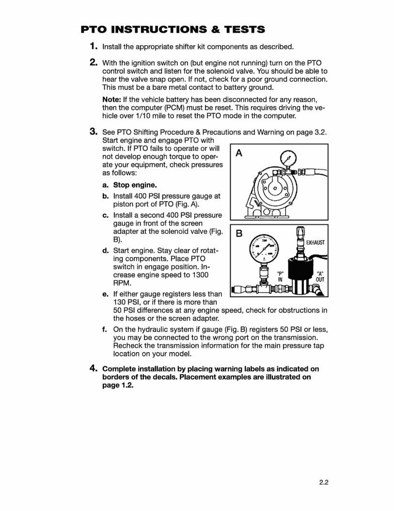
3. See PTO Shifting Procedure & Precautions and Warning on page 3.2. Start engine and engage PTO with switch. If PTO fails to operate or will not develop enough torque to operate your equipment, check pressures as follows:
a. Stop engine.
b. Install 400 PSI pressure gauge at piston port of PTO (Fig. A) .
c. Install a second 400 PSI pressure gauge in front of the screen adapter at the solenoid valve (Fig. B).
d. Start engine. Stay clear of rotating components. Place PTO switch in engage position. Increase engine speed to 1300 RPM.
e. If either gauge registers less than 130 PSI, or if there is more than
A
B
50 PSI differences at any engine speed, check for obstructions in the hoses or the screen adapter.
f. On the hydraulic system if gauge (Fig. B) registers 50 PSI or less, you may be connected to the wrong port on the transmission. Recheck the transmission information for the main pressure tap location on your model.
4. Complete installation by placing warning labels as indicated on borders of the decals. Placement examples are illustrated on page 1.2.
2.2

3.1
SECTION 3 OWNER'S MANUAL
POWER TAKE-OFF WARRANTY The Muncie Power Take-Off is warranted to be free of defects in material or workmanship and to meet Muncie's standard written specifications at the time of sale. Muncie's obligation and liability under this warranty is expressly limited to repairing or replacing, at Muncie's option, within one year after date of original installation any defective part or parts or any product not meeting the specifications.
THIS WARRANTY IS IN LIEU OF ALL OTHER WARRANTIES, EXPRESSED OR IMPLIED. MUNCIE MAKES NO WARRANTY OF MERCHANTABILITY OR OF FITNESS FOR ANY PARTICULAR PURPOSE. MUNCIE'S OBLIGATION UNDER THIS WARRANTY SHALL NOT INCLUDE ANY TRANSPORTATION CHARGES OR COSTS OF INSTALLATION OR ANY LIABILITY FOR DIRECT, INDIRECT SPECIAL, INCIDENTAL, OR CONSEQUENTIAL DAMAGES OR DELAY. THE REMEDIES SET FORTH HEREIN ARE EXCLUSIVE, AND MUNCIE'S LIABILITY WITH RESPECT TO ANY CONTRACT OR SALE OR ANYTHING DONE IN CONNECTION THEREWITH, WHETHER IN CONTRACT, IN TORT, UNDER ANY WARRANTY, OR OTHERWISE, SHALL NOT, EXCEPT AS EXPRESSLY PROVIDED HEREIN, EXCEED THE PRICE OF THE PRODUCT OR PART ON WHICH SUCH LIABILITY IS BASED.
If requested by Muncie, products or parts for which a warranty claim is made are to be returned transportation prepaid to a Muncie Service Center. Any installation or use not in accordance with catalogue or package instructions, other improper use, operation beyond capacity, substitution of parts not approved by Muncie, use with equipment other than the equipment on which the Power Take-Off is first installed, or alteration or repair made to the Power Take-Off other than at a Muncie Service Center shall void this warranty. No employee or representative of Muncie is authorized to change this warranty in any way or to grant any other warranty.

PTO SHIFTING PROCEDURE & PRECAUTIONS PTOs should not be engaged (turned "ON") under heavy load and/or at engine speeds over 1200 RPM. If your operators are careless or negligent in this respect, you can safeguard your equipment with one or more Muncie protective systems.
Do Not operate hydraulic pumps systems without the hydraulic system completely installed.
POWER TAKE-OFF OPERATION - VEHICLE STATIONARY
WARNING! STATIONARY OPERATION REQUIREMENTS:
• Parking brake must always be set • Vehicle's wheels must always be chocked • Transmission must always be in neutral or park
An operator must always be in the driver's seat whenever the engine is running and the transmission is in gear, in order to prevent or stop any unexpected movement of the vehicle which may cause injuries to the operator or others in the vicinity.
Note: If the vehicle battery has been disconnected for any reason, then the computer (PCM) must be reset. This requires driving the vehicle over 1/10 mile to reset the PTO mode in the computer.
1 . See warning above. With the vehicle engine operating at idle, engage the PTO by pushing the rocker switch to the engage position. Release the switch once the PTO is engaged. The rocker switch will rest in the center position.
2. Using a throttle advance device, slowly raise the engine speed to 1200 RPM minimum for engine Diesel applications and 1300 RPM minimum for Gas engine applications. The Maximum allowable operating speed is an engine speed of 2500 RPM.
3. The throttle advance system is not included with the PTO. There are after market kits available to use with Gas engines to automatically advance the engine speed. If you need assistance in obtaining a throttle advance, you can call the Ford Body Builders Advisory staff or Muncie Power Products at the number on the inside front cover of this booklet.
4. The PTO activation system is wired through the vehicle ignition. If you should leave the PTO engaged when you turn off the vehicle the PTO activation will automatically turn off. You will need to go through the activation process again once the engine is restarted.
OVERSPEED PROTECTION PTO overspeed protection is available from Muncie for stationary applications. Consult your Muncie product literature or call your nearest Muncie Power Center for information on the SPD-1001 A System Protection Device. The SPD is adjustable for maximum engine speed and can also prevent engagement of your PTO at unsafe engine speeds.
3.2

POWER TAKE-OFF OPERATION - VEHICLE MOBILE 1. With the vehicle engine operating at idle and the parking brake set, engage
the PTO by pushing the rocker switch to the "ENGAGE" position. Release the switch once the PTO is engaged. The rocker switch will rest in the center "ON" position.
2. With the parking brake applied, shift the transmission into a drive or reverse selection. The PTO will stop spinning, until the brake is released and the vehicle has started moving. Stopping the vehicle will cause the PTO to stop because it is torque converter dependent. Once the transmission selector is shifted to "park" or "neutral" the PTO will start to spin again.
3. When PTO switch is active the vehicle will not shift into "overdrive". This is by Ford's design.
PTO MAINTENANCE The Power Take-Off, being an integral part of the transmission, should be serviced at the same intervals as the transmission. Changing transmission fluid should follow the interval recommended by the vehicle manufacturer for severe service. Transmission oil level is important. Checking for PTO leaks and checking the transmission oil level should be done on a regular basis.
The Power Take-Off is also part of a system. The PTO system may include the activation control parts, a driveshaft, or hydraulic pump. This PTO system requires periodic checks and service. Typically the interval for maintenance checks of the PTO system depends on the application of the system. Every time the chassis is lubricated or a mechanic is under the vehicle the PTO system should be checked and/or serviced. For severe duty PTO system applications, it is recommended that the system be checked for service every 100 hours of use (this guideline can be adjusted based on past service history once you have it established). Service should include checking and lubricating direct mount pump shaft connections. PTO gears can be checked for wear by removing the PTO. If pitting, galling, cracking, or deformation of the gears or splines has occurred, then the PTO needs to be rebuilt or replaced.
Within the first week of use, recheck the installation of the PTO. Check for leaks and loose mounting hardware. At regular maintenance intervals, check adjustments and lubricate moving parts, tighten and repair the connections, mounting hardware. Pumps that are mounted directly to the PTO output require the application of an anti-seize or a high temperature, high pressure grease. (Muncie PTOs are initially supplied with the required grease.) The purpose of this grease is to help make the PTO easier to service and to reduce the effects of fretting corrosion on the mating PTO and pump shafts. PTO applications under severe duty cycles and/or high torque requirements may require servicing this shaft connection by periodically regreasing the shafts. Fretting corrosion cannot be stopped by applying grease, the grease is only a deterrent.
PTO TORQUE & HORSEPOWER RATINGS Intermittent service refers to an On-Off operation under load. If maximum horsepower and/or torque is used for extended periods of time, (5 minutes or more) this is considered "Continuous Service" and the horsepower rating of the PTO should be reduced by multiplying the value below by . 70.
PTO SPEED INTERMIT. INTERMIT. TORQUE TORQUE MAX. HP@1000 KW@1000 SERIES RATIO RPM RPM LBS.FT. NM SPEED
FA 06 24 17 127 172 2500
3.3

PTO TROUBLESHOOTING GUIDE
PROBLEM POSSIBLE CAUSE REMEDY PREVENTION
FA SERIES PTOS
PTO does Ford required Inspect and reconnect Refer to wiring diagram not Engage wiring installation not PTO activation wire on Page 2.1 *
followed. connection on the PTO harness.
Contaminated hy- Remove contaminants Change transmission draulic activation from piston area. oil filter lines
Rocker switch Remove connection at Make sure green wire in incorrectly rocker switch, check connector is at the top connected pins and re-install per when installed
instructions on pages 1.10-1.11.
Transmission hy- Hydraulic line con- Review installation draulic pressure not nected to the wrong diagrams on page 2.1 high enough port.
Burned or extremely Replace worn Use proper shift worn clutch pack components procedures
PTO does Faulty hydraulic sole- Repair or replace Sometime a result not noid valve of contamination or disengage dirty valve
Burned or extremely Repair or replace Follow proper engage-worn clutch pack components ment procedures. See
page 3.2
PTO en- Ford required Inspect and reconnect Refer to wiring diagram gages wiring installation not PTO activation wire on Page 2.1 * Low/No out- followed connection on the PTO put speed harness or pump Transmission selector Operate PTO in neutral Refer to operating in-flow in drive mode and op- or park. Operation will structions on Pages
erator foot on brake only occur while vehi- 3.2 & 3.3 or parking brake set cle is moving due to
torque converter slip
*When properly connected there should be approx. 120-130 psi oil pressure at PTO solenoid, with engine running and with transmission selector in "Park". The PTO activation wire connects directly to the PCM at Pin #4 (Gas) or Pin #66 (Diesel).
3.4

Muncie® Power Products
ISO 9001
II -Muncie Power Products, Inc. Member of the lnterpump Hydraulics Group General Offices and Distribution Center• P.O. Box 548 • Muncie, IN 47308-0548 • (765) 284-7721 FAX (765) 284-6991 • E-mail [email protected] • Web site http://www.munciepower.com Drive Products, Exclusive Agents for Canada, ISO Certified by an Accredited Registrar
IN97 ~as (Rev. 12-09) Printed in the U.S.A. © Muncie Power Products, Inc. 201 0