
MULTITRACK REMOTE CONTROLLER - Hyperrealmachines.hyperreal.org/manufacturers/Akai/manuals/... ·...
192
MULTITRACK REMOTE CONTROLLER Operator’s Manual WARNING To prevent fire or shock hazard, do not expose this appliance to rain or moisture. 000420-3 Printed in Japan
Transcript of MULTITRACK REMOTE CONTROLLER - Hyperrealmachines.hyperreal.org/manufacturers/Akai/manuals/... ·...

MULTITRACK REMOTE CONTROLLER
re32
Operator’s Manual
WARNINGTo prevent fire or shock hazard, do notexpose this appliance to rain or moisture.
000420-3 Printed in Japan

Page i
The lightning flash with arrowhead symbol , within an equilateral triangle, isintended to alert the user to the presence of uninsulated “dangerous voltage”within the product’s enclosure; that may be of sufficient magnitude toconstitute a risk of electric shock to persons.
The exclamation point within an equilateral triangle is intented to alert the userto the presence of important operating and maintenance (servicing) instruc-tions in the literature accompanying the appliance.
THE SYMBOLS ARE RULED BY UL STANDARDS (U.S.A.)
5B-En
WARNING!!To prevent fire or shock hazard, do not expose this appliance to rain or moisture.
1-En
CAUTION: TO REDUCE THE RISK OF ELECTRIC SHOCKDO NOT REMOVE COVER (OR BACK).
NO USER-SERVICEABLE PARTS INSIDE.REFER SERVICING TO QUALIFIED SERVICE PERSONNEL.
CAUTIONRISK OF ELECTRIC SHOCK
DO NOT OPEN
Important Notice
The material in this document is copyright to AKAI professional M.I. Corp., and may not bequoted or reproduced in any form without written permission from the company.
LIMITED SOFTWARE WARRANTY POLICYAll the software provided with, or purchased especially for, AKAI professional products hasbeen tested for functionality. AKAI professional M.I. Corp. will make its best efforts to correctreported software defects for future releases subject to technical practicabilities.AKAI professional M.I. Corp. makes no warranty or representation either expressed orimplied with respect to the system's performance or fitness for a particular purpose.In no event will AKAI professional M.I. Corp. be liable for direct or indirect damages arisingfrom any defect in the software or its documentation. Further, AKAI professional M.I. Corp.will not accept any liability for any programs, sounds, audio recording or sequences stored inor used with AKAI professional products, including the cost of recovery of such data.The warranties, remedies and disclaimers above are exclusive and take precedence over allothers, oral or written, express or implied, to the extent permitted by law in the geographicalarea of the product's use. No employee of AKAI professional M.I. Corp., agent, distributor oremployee of an agent or distributor is authorised to offer any variation from this policy.
Rev. 3 4/20/2000

Page ii
WARNING
WARNING
The RE32 is designed to be used in a standard household environment.Power requirements for electrical equipment vary from area to area. Please ensure that yourRE32 meets the power requirements in your area. If in doubt, consult a qualified electrician orAKAI professional dealer.
120VAC @ 60Hz for USA and Canada220-230/240VAC @ 50Hz for Europe240VAC @ 50Hz for Australia
PROTECTING YOURSELF AND THE RE32
• Never touch the AC plug with wet hands.
• Always disconnect the RE32 from the power supply by pulling on the plug, not the cord.
• Allow only an AKAI professional dealer or qualified professional engineer to repair or reas-semble the RE32. Apart from voiding the warranty, unauthorized engineers might touch liveinternal parts and receive a serious electric shock.
• Do not put, or allow anyone to put any object, especially metal objects, into the RE32.
• Use only a household AC power supply. Never use a DC power supply.
• If water or any other liquid is spilled into or onto the RE32, disconnect the power, and call yourdealer.
• Make sure that the unit is well-ventilated, and away from direct sunlight.
• To avoid damage to internal circuitry, as well as the external finish, keep the RE32 away fromsources of direct heat (stoves, radiators, etc.).
• Avoid using aerosol insecticides, etc. near the RE32. They may damage the surface, and mayignite.
• Do not use denaturated alcohol, thinner or similar chemicals to clean the RE32. They willdamage the finish.
• Modification of this equipment is dangerous, and can result in the functions of the RE32 beingimpaired. Never attempt to modify the equipment in any way.
• In order to assure optimum performance of your RE32, select the setup location carefully, andmake sure the equipment is used properly. Avoid setting up the RE32 in the following locations:
1. In a humid or dusty environment2. In a room with poor ventilation3. On a surface which is not horizontal4. Inside a vehicle such as a car, where it will be subject to vibration5. In an extremely hot or cold environment

Page iii
WARNING
THIS APPARATUS MUST BE EARTHED
IMPORTANT
This equipment is fitted with an approved non-rewireable UK mains plug.
To change the fuse in this type of plug proceed as follows:
1) Remove the fuse cover and old fuse.
2) Fit a new fuse which should be a BS1362 5 Amp A.S.T.A or BSI approved type.
3) Refit the fuse cover.
If the AC mains plug fitted to the lead supplied with this equipment is not suitable foryour type of AC outlet sockets, it should be changed to an AC mains lead, completewith moulded plug, to the appropriate type. If this is not possible, the plug should becut off and a correct one fitted to suit the AC outlet. This should be fused at 5 Amps.
If a plug without a fuse is used, the fuse at the distribution board should NOT BEGREATER than 5 Amp.
PLEASE NOTE: THE SEVERED PLUG MUST BE DESTROYED TO AVOID APOSSIBLE SHOCK HAZARD SHOULD IT BE INSERTEDINTO A 13 AMP SOCKET ELSEWHERE.
The wires in this mains lead are coloured in accordance with the following code:
GREEN and YELLOW — EARTH
BLUE — NEUTRAL
BROWN — LIVE
As the colours of the wires in the mains lead of this apparatus may not correspondwith the coloured markings identifying the terminals in your plug, please proceed asfollows:
The wire which is coloured GREEN and YELLOW must be connected to theterminal which is marked with the letter E or with the safety earth symbol orcoloured GREEN or coloured GREEN and YELLOW.
The wire which is coloured BLUE must be connected to the terminal which ismarked with the letter N or coloured BLACK.
The wire which is coloured BROWN must be connected to the terminal which ismarked with the letter L or coloured RED.
THIS APPARATUS MUST BE EARTHEDEnsure that all the terminals are securely tightened and no loose strands of wireexist.
Before replacing the plug cover, make certain the cord grip is clamped over theouter sheath of the lead and not simply over the wires.
6D-En

Page iv
FCC WARNING
This equipment has been tested and found to comply with the limits for a Class B digitaldevice pursuant to Part 15 of the FCC rules. These limits are designed to provide reason-able protection against harmful interference in a residential installation. This equipmentgenerates, uses, and can radiate radio frequency energy and, if not installed and used inaccordance with the instructions, may cause harmful interference to radio communications.However, there is no guarantee that interference will not occur in a particular installation. Ifthis equipment does cause harmful interference to radio or television reception, which canbe determined by turning the equipment off and on, the user is encouraged to try to correctthe interference by one or more of the following measures:
- Reorient or relocate the receiving antenna.
- Increase the separation between the equipment and receiver.
- Connect the equipment into an outlet on a circuit different from that to which the receiver isconnected.
- Consult the dealer or an experienced radio/TV technician for help. 21B-En
CHANGES OR MODIFICATIONS NOT EXPRESSLY APPROVED BY THE MANUFACTURER FORCOMPLIANCE COULD VOID THE USER’S AUTHORITY TO OPERATE THE EQUIPMENT.
32-En
This digital apparatus does not exceed the Class B limits for radio noise emissions fromdigital apparatus set out in the Radio Interference Regulations of the Canadian Depart-ment of Communications.
27-En
AVIS POUR LES ACHETEURS CANADIENS DU RE32
Le présent appareil numérique n’ément pas des bruits radioélectriques dépassant les limitesapplicables aux appareils numériques de la Class B prescrites dans le Règlement sur lebrouillage radioélectrique édicté par le ministère des Communications du Canada
27-F
COPYRIGHT NOTICE
The AKAI RE32 is a computer-based device, and as such contains and uses software in ROMs.This software, and all related documentation, including this Owner’s Manual, contain proprietaryinformation which is protected by copyright laws. All rights are reserved. No part of the software orits documentation may be copied, transferred or modified. You may not modify, adapt, translate,lease, distribute, resell for profit or create derivative works based on the software and its relateddocumentation or any part there of without prior written consent from AKAI professional M.I. Corp.,Yokohama, Japan.
VENTILATIONDo not prevent the unit's ventilation, especially by placing the unit on the soft carpet, in a narrow space,or by placing objects on the unit's chassis—top, side, or rear panels. Always keep the unit's chassisat least 10 centimeters from any other objects.
31C-En

Page v
WARRANTY
AKAI professional M.I. Corp. warrants its products, when purchased from an authorized AKAI professionaldealer, to be free from defects in materials and workmanship for a period of 12 (twelve) months from the dateof purchase. Warranty service is effective and available to the original purchaser only, and only on completionand return of the AKAI professional Warranty Registration Card within 14 days of purchase.
Warranty coverage is valid for factory-authorized updates to AKAI professional instruments and their software,when their installation is performed by an authorized AKAI professional Service Centre, and a properlycompleted Warranty Registration has been returned to your AKAI professional dealer.
To obtain service under this warranty, the product must, on discovery of the defect, be properly packed andshipped to the nearest AKAI professional Service Centre. The party requesting warranty service must provideproof of original ownership and date of purchase of the product.
If the warranty is valid, AKAI professional will, without charge for parts or labour, either repair or replace thedefective part(s). Without a valid warranty, the entire cost of the repair (parts and labour) is the responsibility
of the product’s owner.
AKAI professional warrants that it will make all necessary adjustments, repairs and replacements at no costto the original owner within 12 (twelve) months of the purchase date if:
1 The product fails to perform its specified functions due to failure of one or more of its components.
2 The product fails to perform its specified functions due to defects in workmanship.
3 The product has been maintained and operated by the owner in strict accordance with the writteninstructions for proper maintenance and use as specified in this Operator’s Manual.
Before purchase and use, owners should determine the suitability of the product for their intended use, andthe owner assumes all risk and liability whatsoever in connection therewith. AKAI professional shall not beliable for any injury, loss or damage, direct or consequential, arising out of the use, or inability to use theproduct.
The warranty provides only those benefits specified, and does not cover defects or repairs needed as a resultof acts beyond the control of AKAI professional, including, but not limited to:
1 Damage caused by abuse, accident or negligence. AKAI professional will not cover under warranty anyoriginal factory disk damaged or destroyed as a result of the owner’s mishandling.
2 Damage caused by any tampering, alteration or modification of the product: operating software,mechanical or electronic components.
3 Damage caused by failure to maintain and operate the product in strict accordance with the writteninstructions for proper maintenance and use as specified in this Operator’s Manual.
4 Damage caused by repairs or attempted repairs by unauthorized persons.
5 Damage caused by fire, smoke, falling objects, water or other liquids, or natural events such as rain,floods, earthquakes, lightning, tornadoes, storms, etc.
6 Damage caused by operation on improper voltages.
IMPORTANT NOTE: This warranty becomes void if the product or its software is electronically modified,altered or tampered with in any way.
AKAI professional shall not be liable for costs involved in packing or preparing the product for shipping, withregard to time, labour or materials, shipping or freight costs, or time and expenses involved in transportingthe product to and from an AKAI professional Authorized Service Centre or Authorized Dealer.
AKAI professional will not cover under warranty an apparent malfunction that is determined to be user error,or the owner’s inability to use the product.
THE DURATION OF ANY OTHER WARRANTIES, WHETHER IMPLIED OR EXPRESS, INCLUDING BUTNOT LIMITED TO THE IMPLIED CONDITION OF MERCHANTABILITY, IS LIMITED TO THE DURATIONOF THE EXPRESS WARRANTY HEREIN.
AKAI professional hereby excludes incidental or consequential damages, including but not limited to:
1 Loss of time
2 Inconvenience
3 Delay in performance of the Warranty
4 The loss of use of the product
5 Commercial loss
6 Breach of any express or implied warranty, including the lmplied Warranty of Merchantability, applicableto this product

Page vi
INTRODUCTION........................................................................................................................................... 1FEATURES .................................................................................................................................. 1ABOUT THIS MANUAL ................................................................................................................ 2TERMINOLOGY........................................................................................................................... 3MULTI-MACHINESYSTEM .......................................................................................................... 5REAR PANEL............................................................................................................................... 6SYSTEM CONNECTIONS ........................................................................................................... 7SETTING MACHINE ID NUMBERS ............................................................................................ 8SETTING MACHINE ID NUMBERS - DR16pro ........................................................................... 8SETTING MACHINE ID NUMBERS - DD8 .................................................................................. 8POWERING UP THE RE32 SYSTEM ......................................................................................... 9RE32 PANEL LAYOUT............................................................................................................... 10VGA DISPLAY ............................................................................................................................ 12NAVIGATING THE RE32 ........................................................................................................... 15CURSOR KEYS ......................................................................................................................... 15GETTING AROUND A PROJECT .............................................................................................. 21
GETTING STARTED - BASIC CONCEPTS ............................................................................................... 24CUE............................................................................................................................................ 24EDIT REGION ............................................................................................................................ 24SELECT Q ................................................................................................................................. 24BASIC SYSTEM SETTINGS...................................................................................................... 26FORMATTING DISKS ................................................................................................................ 28VGA SETUP ............................................................................................................................... 31
RECORDING .............................................................................................................................................. 35BASIC RECORDING ................................................................................................................. 35ADVANCED RECORDING ........................................................................................................ 37RECORD DISKS ........................................................................................................................ 40RECORD TYPE ......................................................................................................................... 41RECORD SETUP....................................................................................................................... 43AUTO PUNCH-IN/OUT .............................................................................................................. 46REHEARSE ............................................................................................................................... 46INPUT ROUTING - ASSIGNING INPUTS TO TRACKS ............................................................ 47INPUT ROUTING - DR16pro ..................................................................................................... 48NPUT ROUTING - DD8 (or DD8plus) ........................................................................................ 49INPUT ROUTING - DD1500 ...................................................................................................... 50RECORDING DIGITALLY .......................................................................................................... 52
PLAYING BACK AUDIO MATERIAL .................................................................................................... ..... 54GROUPING TRACKS ................................................................................................................ 57
AUTOLOCATOR.................................................................................................................... ..................... 57LOCATING TO THE START OR END OF A PROJECT ............................................................. 57LOCATING TO THE NEXT OR PREVIOUS CUES ................................................................... 57LOCATING TO TIMECODE POSITIONS................................................................................... 57LOCATING TO LOCATOR MEMORIES .................................................................................... 57STORING LOCATE MEMORIES ............................................................................................... 57CLEARING LOCATE MEMORIES ............................................................................................. 58
CLEARING SINGLE LOCATE MEMORIES ................................................................... 58CLEARING ALL LOCATE MEMORIES........................................................................... 58
CYCLE ....................................................................................................................................... 59PRE-ROLL ................................................................................................................................. 60
EDITING ................................................................................................................................................... 61EDIT KEY ................................................................................................................................... 61EXIT KEY ................................................................................................................................... 61UNDO KEY ................................................................................................................................ 61REDO (SHIFT+UNDO) .............................................................................................................. 61EXECUTE KEY .......................................................................................................................... 61IN KEY ....................................................................................................................................... 61SYNC KEY ................................................................................................................................. 61

Page vii
OUT KEY ................................................................................................................................... 61TO SELECT A WHOLE TRACK ................................................................................................. 62TO SELECT A TRACK FROM THE IN POINT TO THE END .................................................... 62TO SELECT A TRACK FROM THE OUT POINT TO THE START ............................................ 63TO SELECT A TRACK FROM THE SYNC MARK TO THE START OR END............................ 63SELECT Q KEY ......................................................................................................................... 63
MULTI- MACHINE EDIT ............................................................................................................ ................. 64COPYING A REGION ................................................................................................................ 64MULTITRACK PASTE ................................................................................................................ 66MULTITRACK INSERT .............................................................................................................. 66MULTITRACK OVERLAY ........................................................................................................... 67CUT ............................................................................................................................................ 68ERASE ....................................................................................................................................... 68DISCARD ................................................................................................................................... 68SPLIT EDIT ................................................................................................................................ 69
SINGLE MACHINE EDIT ............................................................................................................ ................ 70EDIT CLIPBOARD ..................................................................................................................... 70COPY TO CLIPBOARD ............................................................................................................. 72CUT TO CLIPBOARD ................................................................................................................ 74CUT FORWARDS TO CLIPBOARD (SHIFT+CUT) ................................................................... 75ERASE TO CLIPBOARD ........................................................................................................... 76DISCARD ................................................................................................................................... 77PASTE FROM CLIPBOARD ...................................................................................................... 78PASTING TO OUT AND SYNC REFERENCES ........................................................................ 79INSERT FROM CLIPBOARD ..................................................................................................... 80INSERTING TO OUT AND SYNC REFERENCES .................................................................... 81OVERLAY FROM CLIPBOARD ................................................................................................. 82OVERLAYING TO OUT AND SYNC REFERENCES................................................................. 82MOVE REGION ......................................................................................................................... 83NUDGING IN/SYNC/OUT TIMES .............................................................................................. 84NUDGING AUDIO ...................................................................................................................... 84UNDOING A NUDGE ................................................................................................................. 85NUDGE SET (SHIFT+NUDGE) ................................................................................................. 85SPLIT CUE................................................................................................................................. 86IN->NOW (SHIFT+IN) ................................................................................................................ 87EDIT PLAY KEYS ...................................................................................................................... 90SELECT CUE/EDIT CUE ........................................................................................................... 91USING EDIT CUE TO AFFECT MULTIPLE CUES .................................................................... 94CROSSFADE TOOLS ................................................................................................................ 95
DISK MANAGEMENT ................................................................................................................ ................ 98SAVING PROJECTS.................................................................................................................. 98
SAVING A PROJECT WITH A DIFFERENT NAME ...................................................... 101SAVING LOCATOR MEMORIES OR OTHER SETTINGS ........................................... 101
LOAD ....................................................................................................................................... 102CREATING A NEW PROJECT................................................................................................. 104DISK UTILITIES ....................................................................................................................... 105DISK INFO ............................................................................................................................... 105DISK DIRECTORY ................................................................................................................... 106COPYING FILES/DISKS .......................................................................................................... 107DELETE FILES ......................................................................................................................... 111RENAMING FILES ................................................................................................................... 112BACKING UP YOUR WORK ................................................................................................... 113
BACKING UP TO SCSI TAPE DRIVES ........................................................................ 113FORMATTING A TAPE FOR BACKUP ......................................................................... 114BACKING UP SELECTED FILES ................................................................................. 116BACKING UP ALL PROJECTS AND/OR LIBRARIES .................................................. 117BACKING UP AN ENTIRE DISK .................................................................................. 117PERFORMING THE BACKUP ..................................................................................... 118VERIFYING A BACKUP................................................................................................ 120

Page viii
RESTORING A BACKUP .............................................................................................. 121PERFORMING A RESTORE ........................................................................................ 122RESTORING THE ENTIRE BACKUP .......................................................................... 125NOTES ABOUT BACKUP/RESTORE .......................................................................... 126SUGGESTIONS FOR BACKUP/RESTORE ................................................................. 127TAKING CARE OF YOUR TAPE DRIVE ...................................................................... 128ARCHIVING DATA TO DAT .......................................................................................... 129RESTORING FROM DAT ............................................................................................. 132CLEANUP DISK ........................................................................................................... 133MINIMISE DISK ............................................................................................................ 134
DISK COMPATIBILITY ............................................................................................................. ................ 136MACINTOSH ............................................................................................................................ 136
PROTOOLS IMPORT ................................................................................................... 137CREATING PROTOOLS SESSIONS ........................................................................... 138
WAVEFRAME .......................................................................................................................... 139FAIRLIGHT MFX3PLUS........................................................................................................... 140MSDOS (FAT16) ...................................................................................................................... 140
SYSTEM SETUP ...................................................................................................................................... 141SETUP - MULTI ....................................................................................................................... 142
DISPLAY ....................................................................................................................... 143DISPLAY OFFSET ........................................................................................................ 144FOOTAGE DISPLAY .................................................................................................... 144RECORD SETUP ......................................................................................................... 145SPEED.......................................................................................................................... 148TEMPO MAPS .............................................................................................................. 149CREATING A MIDI TEMPO MAP ................................................................................. 150DELETING TEMPO MAP STEPS ................................................................................ 151LOCATING TO STEPS ................................................................................................. 151
MORE SETUP FUNCTIONS ................................................................................................... 152SAVE SETTINGS ......................................................................................................... 152LOAD SETTINGS ......................................................................................................... 152INFO ............................................................................................................................. 153
SETUP - SINGLE MACHINE ................................................................................................... 154DIGITAL SETTINGS ..................................................................................................... 154DIGITAL OUTPUT FORMAT ........................................................................................ 157OUTPUT DE-EMPHASIS ............................................................................................. 157SYNC SETTINGS ......................................................................................................... 158
RECORD SETUP..................................................................................................................... 162OPERATING LEVELS .............................................................................................................. 162REMOTE PAGES..................................................................................................................... 163GPIO SETUP ........................................................................................................................... 164USER KEYS............................................................................................................................. 168RC15 CONNECTION ............................................................................................................... 170
SYNCING TO EXTERNAL TIMECODE ................................................................................................... 171SETTING TIMECODE OFFSETS ............................................................................................ 172ADVANCED OFFSETS ............................................................................................................ 173
RS422 MASTER CONTROL ........................................................................................................... ......... 175LAYBACK FUNCTION IN RS422 MASTER............................................................................. 176USING THE LAYBACK FUNCTION ......................................................................................... 177RS422 MASTER CONTROL OF NON-LINEAR VIDEO RECORDERS .................................. 178
SPECIFICATIONS .................................................................................................................................... 179
INDEX ................................................................................................................................................ 180-182

Page ix

Version 1.00 1
INTRODUCTION
The staff at AKAI professional would like to thank you for buying the RE32 Multi-track RemoteController. We are confident that the RE32 will be a sound investment, offering many years ofreliable service and will be a product you can rely on in your daily work.
The RE32 is designed to be used with Akai DD/DR-Series Hard Disk Recorders (such as theDR16pro, DD8, DD8plus or DD1500) allowing control of up to 128 tracks of audio.
Dedicated track select keys, transport keys and autolocator functions give the RE32 the feel of aconventional MTR whilst access to sophisticated editing functions are also provided allowing youto edit audio quickly and precisely. The jog wheel allows you to ‘scrub’ audio across all tracks justlike reel rocking ordinary tape.
The RE32 is connected to the machines via Ethernet and includes a built-in VGA display capableof displaying metering and scrolling track information for all of the connected machines. A simplebut effective colour scheme eliminates eye strain even in prolonged sessions. You will no doubt bepleased to know that the screen you see on the monitor is the only one you work in and there areno multiple, stacked ‘windows’ to confuse you!
FEATURES
• Traditional recording and monitoring functions
• Dedicated track select keys for easy selection of play, mute, edit and record.
• Large dedicated MTR-style transport keys.
• The weighted jog wheel allows you to ‘scrub’ audio across all tracks for editing.
• MTR style autolocator with 100 locate memories and 100 ‘grab’ markers.
• Detailed track editing with waveform display.
• Powerful multi-track editing functions,
• LED timecode display
• 248x60 pixel LCD display for parameter settings and function selection.
• PS/2 keyboard input for easy naming of audio takes.
• Custom graphics LSI ensures fast screen re-drawing and updates on any size S-VGA monitor.
• The AKAINET link from the RE32 to the connected machines allows true remote control withvirtually no limit on distance.
TRADEMARKSDigidesign and Protools are registered tademarks of Digidesign and/or Avid Technology, Inc.Macintosh is a registered trademark of Apple Computer Inc. All other trademarks, productand company names are the property of their respective owners.

2 Version 1.00
INTRODUCTION
ABOUT THIS MANUALThis owner’s manual has been written to provide you with the information to get the best from theRE32. Although it hoped that the RE32 is easy enough to use without constant reference to thismanual, please take the time to read it in order to understand the system fully. The manual takesyou through the available functions from scratch, assuming you have just installed it and you areusing it for the first time.
This manual covers all basic functions and operation and, wherever possible, gives hints and tipsand application notes. However, because of the diversity of applications in which the RE32 can beused, it is not always possible to cover every application specifically. As such, most descriptions offunctions are fairly general unless, however, a certain function has a specific use in a particularapplication.
The availability of some functions on the RE32 may depend on the facilities provided by theconnected machines. For example, the DD8plus provides certain features not available on theDR16pro. This manual will give an indication where certain functions may be unavailable. Pleaserefer to the manuals provided with each machine for further details.

Version 1.00 3
INTRODUCTION
As with any piece of new gear, there is always a bit of new jargon to get to grips with. The RE32 isno exception! What follows, therefore, is a short list of some of the terms you will come acrossduring the course of this manual.
GRID This stands for GRaphic Interface Display and refers to the track display on theexternal monitor.
PROJECT This contains all your recordings, edited and positioned as required and shownon the GRID. Think of it as a reel of multi-track tape if you like and the GRID asan animated track sheet.
A PROJECT also contains autolocator memories, MIDI tempo maps, etc., andthese are all saved with the project. The SYSTEM settings are also saved withthe project and when a project is subsequently loaded, the whole system isrestored to exactly the status the project was saved in. For example, the tracksselected for playback, editing and/or record, the sample rate, external timecodeselection, input routing, etc.. All these will be explained later.
Each connected machine actually has its own PROJECT containing audio trackson that machine but the RE32 assembles this information for display on themonitor as a single ‘multi-track’ PROJECT.
NOW TIME In the centre of the GRID are two vertical lines. The centre of these two lines isknown as the NOW TIME and the actual NOW time is shown in the displayabove it (and on the LED timecode display). All work is done with referenced tothis NOW time. For example, to select a cue for editing, move it to the NOWtime and press SELECT Q. Marking IN times and OUT times and locatememories is also done referenced to the NOW time.
CUE This refers to a piece of audio from its start to its end in the GRID. In thismanual, a cue may be referred to as “a stereo cue” - this is actually two monocues across two (normally adjacent) tracks that make up a ‘stereo’ cue.
EDIT REGION This refers to the area selected between the IN and the OUT points. A track (ortracks) must be selected for editing and the edit region is highlighted green onthe external monitor.
IN TIME This usually refers to the start of an edit. However, the IN TIME is used to setauto punch-in and cycle times as well. It is marked by pressing the IN keylocated above the jog wheel.
OUT TIME This usually refers to the end of an edit although it is also used to set autopunch-out and cycle times. It is marked by pressing the OUT key located abovethe jog wheel.
SYNC POINT This is a special marker you can place within an edit region or cue for syncpurposes.
MARK POINT This is a special marker intended for Biphase synchronisation. It can be set todefine a sync point between audio and film (usually a cross before the firstframe).

4 Version 1.00
INTRODUCTION
LIBRARY A library is a file created for convenient storage of groups of cues (referred toas ‘clips’). For example, a library may contain sound effects, or music cues,etc.. Although the library function is not supported on the RE32, several diskrelated functions can be used on disks containing library files made on anothersystem.
MULTI-MODE Most operations on the RE32 are designed to make the system feel like asingle multi-track tape machine even if the tracks are on two or more individualmachine. For example, in a system with two DR16pro machines, selecting‘Track 17’ on the RE32 will actually select Track 1 on the second machine. Thismethod of operation is referred to in this manual as MULTI-MODE.
SINGLE-MODE This refers to an alternate method of operation where each machine is usedindividually. This may be necessary for configuring the system for morecomplicated environments.

Version 1.00 5
INTRODUCTION
MULTI-MACHINE SYSTEMThe followingshows a typical multi-machine system
Audio is recorded through the inputs (analogue and/or digital) directly to project tracks on eachmachine and displayed in the GRID as a multi-track project ready for editing etc.. For example,you may record a long vocal onto track 1, edit out all the mistakes, coughs, breath noises andother unwanted artefacts and simply save the project. You can also copy audio from one region ofthe project to another region as required.
Audio can be recorded directly into the GRID at the timecode position you want it. That audio maysubsequently be edited, crossfaded, etc., as appropriate for the project.
When several machines are connected to the RE32 to expand the total number of tracks available,the system will behave as if there is a single ‘multi-track’ project encompassing all of these tracks.However, in reality each connected machine maintains its own internal project containing data forthe tracks assigned to that machine. Usually, you do not need to worry about the fact that theremay be several machines connected as the RE32 will control them as a single ‘multi-track’ system.However, there may be times when you want to do something specifically on one machine and theRE32 will allow you to do this as well if you wish as explained during the course of this manual.
Of course, your setup need not be as elaborate as the one shown above and an RE32 with justone or two 16-track machines is a powerful combination.
6 Version 1.00
INTRODUCTION
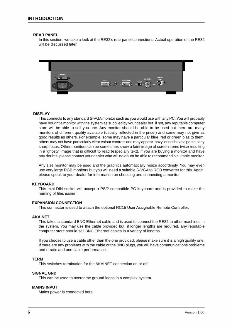
REAR PANELIn this section, we take a look at the RE32’s rear panel connections. Actual operation of the RE32will be discussed later.
DISPLAYThis connects to any standard S-VGA monitor such as you would use with any PC. You will probablyhave bought a monitor with the system as supplied by your dealer but, if not, any reputable computerstore will be able to sell you one. Any monitor should be able to be used but there are manymonitors of different quality available (usually reflected in the price!) and some may not give asgood results as others. For example, some may have a particular blue, red or green bias to them,others may not have particularly clear colour contrast and may appear ‘hazy’ or not have a particularlysharp focus. Other monitors can be sometimes show a faint image of screen items twice resultingin a ‘ghosty’ image that is difficult to read (especially text). If you are buying a monitor and haveany doubts, please contact your dealer who will no doubt be able to recommend a suitable monitor.
Any size monitor may be used and the graphics automatically resize accordingly. You may evenuse very large RGB monitors but you will need a suitable S-VGA to RGB converter for this. Again,please speak to your dealer for information on choosing and connecting a monitor.
KEYBOARDThis mini DIN socket will accept a PS/2 compatible PC keyboard and is provided to make thenaming of files easier.
EXPANSION CONNECTIONThis connector is used to attach the optional RC15 User Assignable Remote Controller.
AKAINETThis takes a standard BNC Ethernet cable and is used to connect the RE32 to other machines inthe system. You may use the cable provided but, if longer lengths are required, any reputablecomputer store should sell BNC Ethernet cables in a variety of lengths.
If you choose to use a cable other than the one provided, please make sure it is a high quality one.If there are any problems with the cable or the BNC plugs, you will have communications problemsand erratic and unreliable performance.
TERMThis switches termination for the AKAINET connection on or off.
SIGNAL GNDThis can be used to overcome ground loops in a complex system.
MAINS INPUTMains power is connected here.
Version 1.00 7
INTRODUCTION
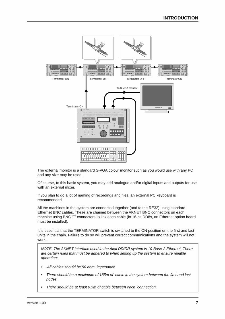
The external monitor is a standard S-VGA colour monitor such as you would use with any PCand any size may be used.
Of course, to this basic system, you may add analogue and/or digital inputs and outputs for usewith an external mixer.
If you plan to do a lot of naming of recordings and files, an external PC keyboard isrecommended.
All the machines in the system are connected together (and to the RE32) using standardEthernet BNC cables. These are chained between the AKNET BNC connectors on eachmachine using BNC ‘T’ connectors to link each cable (in 16-bit DD8s, an Ethernet option boardmust be installed).
It is essential that the TERMINATOR switch is switched to the ON position on the first and lastunits in the chain. Failure to do so will prevent correct communications and the system will notwork.
NOTE: The AKNET interface used in the Akai DD/DR system is 10-Base-2 Ethernet. Thereare certain rules that must be adhered to when setting up the system to ensure reliableoperation:
• All cables should be 50 ohm impedance.
• There should be a maximum of 185m of cable in the system between the first and lastnodes.
• There should be at least 0.5m of cable between each connection.
Terminator ON Terminator ON
Terminator ON
Terminator OFF
To S-VGA monitor
Terminator OFF
MULTITRACK REMOTE CONTROLLER
INPSTOLOC
REMOTE
REMOTE

8 Version 1.00
INTRODUCTION
SETTING MACHINE ID NUMBERSWhen multiple machines are connected to the RE32, each must be assigned a unique MACHINENUMBER before the system is used for the first time. These must be assigned sequentially from 1to the number of machines in the system and are used to allocate tracks to machines by the RE32.
Example 1: With two DR16pro machines:
Machine “1” = Tracks 1-16Machine “2” = Tracks 17-32
Example 2: With three DD8 machines:
Machine “1” = Tracks 1-8Machine “2” = Tracks 9-16Machine “3” = Tracks 17-24
Please refer to the machine’s own operators manual for detailed information. The following isintended to provide a brief description relevant to certain machines:
SETTING MACHINE ID NUMBERS - DR16pro The DR16pro’s MACHINE NUMBER assignment may be set as follows:
1. Press the SUB-MENU key followed by the 3 (SETUP) key on the numeric keypad thenselect AKAINET on the display by rotating the JOG/SHUTTLE control.
2. Press the STORE/ENT key. The message MACHINE 01 will appear in the display showingthe current Machine ID.
3. Use the JOG wheel to select the required Machine ID number and press the STORE/ENTkey to confirm the assignment and exit the menu.
SETTING MACHINE ID NUMBERS - DD8 The DD8’s MACHINE NUMBER assignment is set on the AKNET INFO page which is accessedfrom REMOTE page in the SYSTEM menus. On the front panel of the DD8, press the SYSTEMkey, followed by the MORE (F6) key then the REMOTE key (F2). Finally, press the AKNET key(F1) and you will see the following screen:
Note: DD8’s front panel LCD
The NUMBER field shows the MACHINE NUMBER currently assigned. You may change the numberusing the DATA +/- keys and then save the new setting to flash ROM.
NOTE: Please refer to the operators manual provided with each machine for more detailedinformation about setting MACHINE NUMBERs.

Version 1.00 9
INTRODUCTION
POWERING UP THE RE32 SYSTEMFirst, turn on any disk drives that may be connected to the system. Next, turn on the individualmachines (DR16pro, DD8plus etc.). The machines will ‘talk to’ their disk drives and you will seesome disk activity as they do this. When this has settled down, turn on the RE32. The externalmonitor screen can be switched on at any time and will have no effect on the system.
When you power up the RE32, the RE32 will scan the ethernet bus for connected machines. Youwill see this screen display momentarily:
A few seconds later, you will see this screen:
This indicates that the RE32 has successfully established communications with the connectedmachines. A few seconds after the RE32 is booted, you will see this screen which indicates thatthe system is ready for use:
If there is a problem with the AKAINET connections, the system will display this screen permanently:
This indicates that the RE32 has detected a fault and cannot communicate with the connectedmachines. If this occurs, check the AKAINET BNC cables to make sure they are securely connected.If that seems o.k., check the AKAINET termination switches. As shown in the diagram in theprevious section, the TERMINATOR must be switched ON on the first and last devices in the chainand switched OFF on all other devices.
If this doesn’t work, try powering everything down and trying again. If you still find that you cannotboot up, please contact your dealer.
But take heart! This should not happen and if you do have problems, you will probably find it isnothing more serious than a damaged AKAINET BNC cable or that the AKAINET termination hasbeen incorrectly set. If these are alright, however, but the problem persists, you should contactyour dealer.

10 Version 1.00
INTRODUCTION
PANEL LAYOUTThe RE32 is an MTR style remote controller with many commonly used functions available ondedicated keys. If you break down the RE32’s panel into its various sections, it really is quitestraightforward to understand and use.
MULTITRACK REMOTE CONTROLLER
INPSTOLOC
Track Select Keys
Track Mode
Timecode Display
LCD Jog Wheel
Utilities
Data Entry
Transport Keys
Across the top of the panel are the track select keys. The top row of keys are used to turn tracks onand off for playback. The second row of keys are used to either select tracks for recording or forediting. When these keys are showing edit tracks, they are illuminated in green whilst record trackselections are shown illuminated in red.
The TRACK MODE keys are used to setup the function of the track select keys.
The TRACKS key is used to select which bank oftracks are currently assigned to the 32 track keys.
The RE32 can control up to 128 tracks in 4 banks.The currently selected bank is indicated by thecolumn of LEDs next to the TRACKS key.
The GROUP keys allow you to store and recall combinations of track settings.
The LCD displays information concerning the status of the system at any time as well as beingused to provide soft keys, the function of which changes according to the system’s status.
The TIMECODE DISPLAY shows the current now time.
The UTILITIES keys give you access to functions such as DISK, SETUP, EDIT, PREROLL etc..The amber SHIFT key gives access to keys’ sub-functions and these are shown in amber textbeneath the keys.
The TRANSPORT keys provide the basic PLAY, STOP, REWIND, FAST FORWARD, etc.. Theyalso offer special ‘edit play’ keys used when editing and these include PLAY TO, PLAY FROM etc..
TRACKS
65-96
1-32
97-128
33 - 64

Version 1.00 11
INTRODUCTION
Located directly beneath the LCD is a row of six soft keys, the function of which depends on theRE32’s current status.
The JOG wheel emulates reel rocking for finding edit points. It is possible to jog all trackssimultaneously.
The DATA ENTRY section includes a numeric keypad for inputting timecode and values and forselecting locator memories and edit clipboards. The +/- DATA ENTRY keys allows you to setparameter values whilst the CURSOR keys are used for selecting parameter fields in the RE32’sLCD. The +/- DATA ENTRY keys can also be used to nudge audio into sync and to go to the nextand previous cues and the CURSOR keys double as vertical and horizontal zoom keys. TheSCROLL VIEW keys are used to scroll the vertical selection of tracks currently being shown on theVGA.
12 Version 1.00
INTRODUCTION
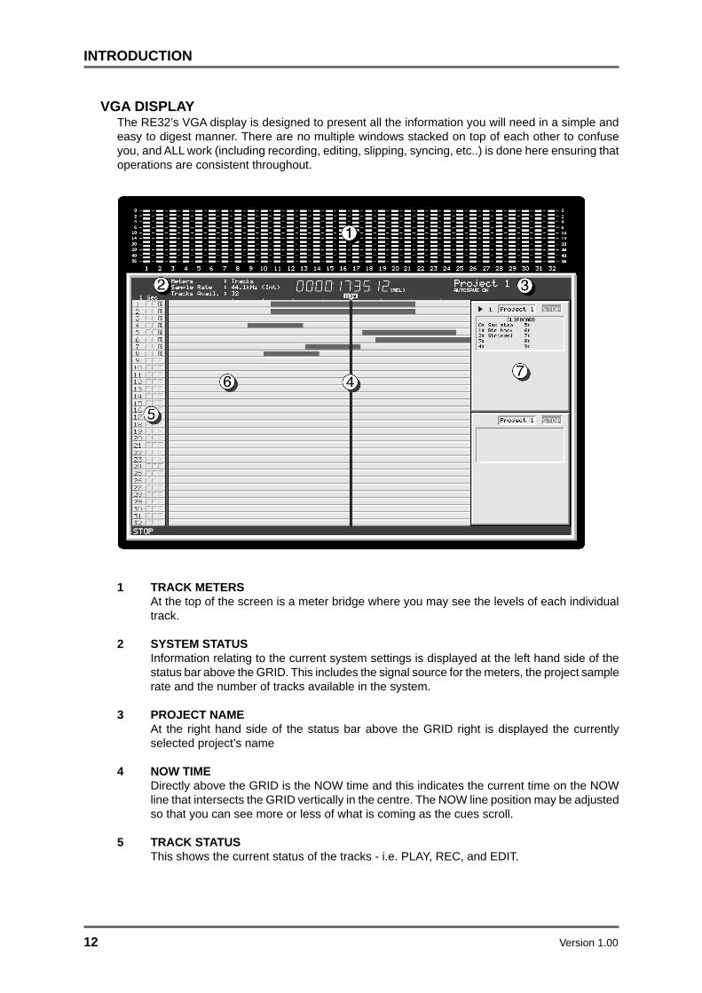
VGA DISPLAYThe RE32’s VGA display is designed to present all the information you will need in a simple andeasy to digest manner. There are no multiple windows stacked on top of each other to confuseyou, and ALL work (including recording, editing, slipping, syncing, etc..) is done here ensuring thatoperations are consistent throughout.
1 TRACK METERSAt the top of the screen is a meter bridge where you may see the levels of each individualtrack.
2 SYSTEM STATUSInformation relating to the current system settings is displayed at the left hand side of thestatus bar above the GRID. This includes the signal source for the meters, the project samplerate and the number of tracks available in the system.
3 PROJECT NAMEAt the right hand side of the status bar above the GRID right is displayed the currentlyselected project’s name
4 NOW TIMEDirectly above the GRID is the NOW time and this indicates the current time on the NOWline that intersects the GRID vertically in the centre. The NOW line position may be adjustedso that you can see more or less of what is coming as the cues scroll.
5 TRACK STATUSThis shows the current status of the tracks - i.e. PLAY, REC, and EDIT.

Version 1.00 13
INTRODUCTION
6 GRIDThe GRID (GRaphic Interface Display) shows the audio as waveforms and/or as blocks andyou may choose whether to display waveforms or not according to your preference. Consistentcolour coding is used throughout - blue for play, grey for muted, red for record, green for editand light brown (ochre) for EDIT CUE. This allows you to see at a glance the status of thetracks even from a distance. The waveforms/blocks scroll during playback and you mayzoom in horizontally or vertically for more precise editing and the RE32’s real-time operatingsystem even allows you to zoom in or out when the machine is currently busy doing otherthings such as playing back, recording, etc.. It is also possible to show cue names andthese are shown in a column on the right of the GRID.
7 CLIPBOARDSWhen Single Machine Edit Mode is selected, these panels are shown on the right hand sideof the screen. Each panel is aligned vertically with the tracks related to the correspondingmachine.
1 Project 1Project 1
CLIPBOARD
O: Sax stab
1: Gtr hook
2: Strings1
3:
4:
5:
6:
7:
8:
9:
STOP
The top line of this box shows the machine number, the name of the project currently loadedon this machine and the current transport status (PLAY, STOP etc..)
The symbol is shown alongside the currently selected machine. The next box displayseither the current project name or the machine name, depending on the setting in theINFORMATION field on the SHOW ON VGA MONITOR - MACHINES page. This box will becoloured red while the machine is in record and in a mustard colour while the machine is inrehearsing a record. The final box displays the machines transport status (STOP, PLAYetc..).
Below this are shown the edit clipboards available on this machine. These are the ten editsavailable for pasting and/or inserting into a project at any time. The EDIT CLIPBOARD willbe explained fully later in the section “EDITING”.

14 Version 1.00
INTRODUCTION
CUE NAME DISPLAYTo the right of the track display, you may choose to see the names of the cue(s) currently beingplayed. This is used instead of the normal convention on other hard disk recorders where thename is shown within the cue itself because with short cues, the name often gets abbreviated intosomething meaningless. This can also make the screen very cluttered. On the RE32, you see theentire name regardless of its length.
For example:
MUSIC 1 R
MUSIC 1 L
FO
FO
FO
FO
FO
FO
FO
FO
FO
FO
FO
FO
‘Conventional’ disk recorder cue name display.
Whilst the long music cue can display the full name, the footsteps SFX on the adjacent tracks(called FOOTSTP 1L and FOOTSTP 1R) are abbreviated to FO. Compare this with the RE32:
FOOTSTP1 R
MUSIC 1 L
MUSIC 1 R
FOOTSTP1 L
RE32 cue name display.
On the RE32, regardless of the length of the cue, the entire name is shown clearly.

Version 1.00 15
INTRODUCTION
NAVIGATING THE RE32
Getting around the RE32 is quite straightforward. Dedicated keys for most commonly used functionsreduces the need for multi-menu operation. Less day-to-day functions are kept hidden away out ofharms way but are still readily accessible.
The external monitor is used purely for referencing your work to see what is going on. You canthink of it as an animated track sheet. In theory, the RE32 could be used without it as most work isdone from the RE32’s front panel LCD.
The keys we will look at in this section are highlighted in the above diagram although others maybe referred to where necessary.
CURSOR KEYSYou use the four CURSOR keys to move around the LCD. In the following example, the page isdisplaying a list of files and the CURSOR keys are used to scroll up and down the list in order toselect one.
You can also, in this example, move the cursor to the top line to select a different disk. Diskselection would be made using the DATA ENTRY +/- keys or by typing in a number directly fromthe numeric keypad.
NOTE: The two arrows shown in this example indicate that there are files ‘above’ and ‘below’the screen which may be accessed by scrolling up or down. This is a convention used in allfile-lists in the RE32 (for example, when loading PROJECTS etc.). If the arrows don’t appear,there are no files ‘off-screen’.
The cursor keys are ‘accelerators’ - that is, they move faster the longer you hold them so scrollingthrough long lists of files or parameters is very fast.
16 Version 1.00
INTRODUCTION
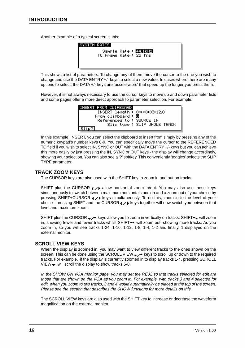
Another example of a typical screen is this:
This shows a list of parameters. To change any of them, move the cursor to the one you wish tochange and use the DATA ENTRY +/- keys to select a new value. In cases where there are manyoptions to select, the DATA +/- keys are ‘accelerators’ that speed up the longer you press them.
However, it is not always necessary to use the cursor keys to move up and down parameter listsand some pages offer a more direct approach to parameter selection. For example:
In this example, INSERT, you can select the clipboard to insert from simply by pressing any of thenumeric keypad’s number keys 0-9. You can specifically move the cursor to the REFERENCEDTO field if you wish to select IN, SYNC or OUT with the DATA ENTRY +/- keys but you can achievethis more easily by just pressing the IN, SYNC or OUT keys - the display will change accordingly,showing your selection. You can also see a ‘?’ softkey. This conveniently ‘toggles’ selects the SLIPTYPE parameter.
TRACK ZOOM KEYSThe CURSOR keys are also used with the SHIFT key to zoom in and out on tracks.
SHIFT plus the CURSOR allow horizontal zoom in/out. You may also use these keyssimultaneously to switch between maximum horizontal zoom in and a zoom out of your choice bypressing SHIFT+CURSOR keys simultaneously. To do this, zoom in to the level of yourchoice - pressing SHIFT and the CURSOR keys together will now switch you between thatlevel and maximum zoom.
SHIFT plus the CURSOR keys allow you to zoom in vertically on tracks. SHIFT+ will zoomin, showing fewer and fewer tracks whilst SHIFT+ will zoom out, showing more tracks. As youzoom in, so you will see tracks 1-24, 1-16, 1-12, 1-8, 1-4, 1-2 and finally, 1 displayed on theexternal monitor.
SCROLL VIEW KEYSWhen the display is zoomed in, you may want to view different tracks to the ones shown on thescreen. This can be done using the SCROLL VIEW keys to scroll up or down to the requiredtracks. For example, if the display is currently zoomed in to display tracks 1-4, pressing SCROLLVIEW will scroll the display to show tracks 5-8.
In the SHOW ON VGA monitor page, you may set the RE32 so that tracks selected for edit arethose that are shown on the VGA as you zoom in. For example, with tracks 3 and 4 selected foredit, when you zoom to two tracks, 3 and 4 would automatically be placed at the top of the screen.Please see the section that describes the SHOW functions for more details on this.
The SCROLL VIEW keys are also used with the SHIFT key to increase or decrease the waveformmagnification on the external monitor.

Version 1.00 17
INTRODUCTION
NUMERIC KEYPADThe NUMERIC KEYPAD has two main functions. It is used to store and recall up to 10 edits inwhat we call the EDIT CLIPBOARD (see the section on editing that describes this). It is also usedfor timecode and numeric entry.
EDITING NUMERIC FIELDSTo edit number fields, you can just type the number directly followed by ENT on the numerickeypad or the main EXECUTE key. You may also use the DATA ENTRY +/- keys to increment/decrement through the values.
If you make a mistake, press EXIT - this will restore the parameter’s previous value.
EDITING NAMES THAT INCLUDE NUMBERSIn names that have a number as part of the name (i.e. PROJECT 5), this can be renamed veryquickly simply by pressing any other number on the numeric keypad. For example, pressing 9would immediately change this name to PROJECT 9. This can be useful when saving a projectwith a different name (SAVE AS). It is also useful for quickly renaming libraries or clips.
ENTERING TIMECODE VALUESTimecode is entered using the NUMERIC KEYPAD. Values enter from the right and time divisions(i.e. hours, minutes, seconds and frames) are confirmed using the keypad’s 00 ‘double zero’ key.
For example, to enter a value of 1 hour, 23 minutes, 12 seconds, 12 frames, type the following:
1, 00, 23, 00, 12, 00, 12, 00, ENT
You will see the following display in the selected timecode field as you enter the numbers:
00
10023
12
00
ENT
12
The important thing to remember is to ‘confirm’ the time division using the numeric keypad’s 00‘double zero’ key.
If you make a mistake when entering a timecode value, press EXIT. This will restore the field’sprevious timecode entry and you may try again.
It is also possible to ‘nudge’ timecode entries. You can move the cursor ‘within’ the timecode fieldby pressing SHIFT+DATA ENTRY +/-. As an example, in EDIT CUE, you may wish to nudge a fadeup time from 2 seconds to 3 seconds. Rather than type in 3, 00, EXECUTE, move the cursor to theseconds field using SHIFT+DATA ENTRY +/- as appropriate and use the DATA ENTRY + key toincrement by one. For example:
The digit is highlighted with an ‘underbar’. Now press SHIFT + DATA ENTRY ‘-’ to move the cursorleft and press the DATA ENTRY + key:
In this way, instead of having to type out long strings of timecode numbers, you can nudge atimecode field to a value quite easily.

18 Version 1.00
INTRODUCTION
DATA ENTRY/NUDGE KEYSThese two keys allow you to set data values.
To set a data value, simply move the cursor to appropriate field and press the DATA ENTRY ‘+’ keyto increase the value or the DATA ENTRY ‘-’ key to decrease the value. Like the CURSOR keys,these keys are ‘accelerators’ that get gradually faster the longer you keep them held down, allowingrapid changes to be made to long parameter fields.
These keys are also used with the SHIFT key to move the sub-cursor left or right within a parameterfield as described above for entering timecode values.
USING THE SOFT KEYSThe soft keys perform two main functions. One is to take you to another page, another is toperform some kind of action.
Page keys are highlighted - i.e.: will take you to the disk page.
Action keys are ‘hollow’ - i.e.: will save the current file.
There is another type of action key that we saw a bit earlier and the is the ‘?’ action key. These useLower case characters and refer to the name of the parameter they are linked to. These allow youto switch parameters in the field they refer to.
There are also double width soft keys: or
These may be page keys (highlighted) or ‘action’ keys (hollow) as described above. There canalso be double width ‘?’ action keys. When a double width key is used, either of the soft keysdirectly below it may be used.
In some pages, the soft keys act as ‘radio’ keys - i.e. switching one on will switch one or moreothers off - and select different functions. In this case, the selected key highlights. Although theselook essentially like ‘action’ keys or ‘page’ keys, the distinction should be clear from the context ofthe page you are in.
EXECUTENearly all actions on the RE32 require completion using the EXECUTE key located beneath thesoft keys. This key has a LED in it that will flash indicating that it should be pressed to complete theaction. You may also receive a prompt to tell you to press EXECUTE. Sometimes, where multipleprompts are shown (i.e. “DELETE SELECTED FILE?” followed by “ARE YOU SURE? NO UNDO!!”),the EXECUTE key will remain flashing until the whole process has been completed. Basically,whenever the EXECUTE key is flashing, this indicates that you must press it to complete anaction.
EXECUTE can also be used to complete entering a name or number or timecode value.
EXITWhenever the EXECUTE can be used (i.e. its LED is flashing), the EXIT key will abort or cancelthe process without committing it. This is your ‘escape route’ should you be in a situation whereyou change your mind. The EXIT key also functions as a “NO” key in situations where YES/NOresponses are required.
At all times, the EXIT key will take you out of the current page and back to a ‘safe’ situation.
In cases where you have arrived at a page by going through other pages first (for example, SETUP,DISP, OFFSET) the EXIT key will take you back step by step through those pages until you arriveback at the main display.

Version 1.00 19
INTRODUCTION
UNDOThe UNDO key offers twenty levels of undo and redo. If you make a mistake and do somethingyou’re not happy with, press UNDO and the original data will be restored. If you then find that youpreferred the mistake, press REDO (SHIFT+UNDO).
You may undo/redo the last twenty things you did by repeatedly pressing UNDO or REDO(SHIFT+UNDO). This allows you to try a few edits out in succession and then, if you don’t like theresults, restore the original version.
NOTE 1: The UNDO function only refers to recording and editing. You cannot undo anythingelse. For example, if you load a project and change your mind, you cannot undo that. If youselect some tracks for edit when you really meant to select them for record, you cannot undothat.
NOTE 2: IT IS NOT POSSIBLE TO USE UNDO IF YOU DELETE A FILE (I.E. A PROJECT)BY MISTAKE. PLEASE TAKE CARE WHEN DELETING FILES.
SHIFTThe amber SHIFT key gives access to sub-functions on certain keys. Most keys’ sub-functionsrelate to the key itself (for example, many keys have sub-functions to SET parameters associatedwith the main function of the key).
When using certain sub-functions such as VGA (SHIFT+SETUP), XFADE (SHIFT+EDITQ), thekeys’ LEDs flash indicating you are the key’s ‘alternative’ function.
SET FUNCTIONSSome keys’ SHIFT function is SET, allowing you to set up certain parameters relevant to the key(for example, SHIFT+PREROLL allows you to set the preroll time). When using SET pages, theLED will not flash but will be lit according to whether that key is switched ON or OFF (for example,when setting the PREROLL time, the LED will indicate whether the PREROLL function is turnedon or off.
NOTE: Not all keys’ SET functions are operational. Some of the SET functions are reservedfor future enhancements via software.
JOG WHEELThe jog wheel is normally used to ‘scrub’ audio when finding edit points. It is possible to jog alltracks simultaneously. You may also use the jog wheel to ‘spool’ through a project and the jogwheel acts as a speed control for forwards or backwards playback.
The function of the jog wheel is selected by pressing the JOG key to toggle the function. Thecurrent function is indicated by the JOG/SHUTTLE LEDs located next to the key. When both LEDsare lit, this selects a special ‘JOG VIEW’ mode which allows you to jog through the project butwithout audio.
NAMING FILESAlthough the RE32 has an auto-naming function for naming recordings, projects, etc., sometimesit is necessary to name files yourself. Typically, you want to name projects, libraries and clips mostof the time and you may wish to name edits prior to copying them into the clipboard.
Naming is usually done from a PS/2 ASCII keyboard connected to the RE32. The computer keyboardis connected to the KEYBOARD input on the rear of the RE32.
When the cursor is placed on a filename and a key is pressed on the PS/2 keyboard, the selectedfile will be highlighted thus ready for editing:
The first character of the name will be highlighted and you may type in a name of up to tencharacters.
20 Version 1.00
INTRODUCTION
As the LCD prompts you, you must press EXECUTE to complete the naming process. If youchange your mind, press EXIT at any time. Pressing EXIT will leave the naming process andrevert to the original name.
When using a computer keyboard, you will note that the numeric keypad functions just like theRE32’s. You will also note that you can use the keyboard’s first six function keys to duplicate theRE32’s soft keys. ESC(ape) duplicates the action of the RE32’s EXIT key. SHIFT and CAPSLOCK work as you would expect as do the cursor keys which duplicate the action of the RE32’sCURSOR keys. In fact, for the most part, you will find that the keyboard performs much like itwould when used with a computer.
NOTE: The following characters are not available from the computer keyboard:
£ $ ^ & { } [ ] @ | ~ ‘ + -
The following keys also have no function:
TAB CTRL ALT PAGE UP PAGE DOWNHOME END F7-F12 PRINT SCREEN SCROLL LOCK
RENAMING FILESThere will be occasions where you want to rename an existing project, library or clip. Renaming isexactly the same as naming a file - move the cursor to the file you wish to rename and start typingto enter a suitable name.
You may also re-name existing files that have a number in them very quickly just be pressing anyof the numeric keys. For example, you can rename PROJECT 1 to PROJECT 2 simply by pressing2, EXECUTE.
You can also add numbers to files in this way. For example, to re-name the file ANIMALS toANIMALS 1, simply move the cursor to the file, press 1, EXECUTE. Again, pressing EXIT will abortthe naming process.
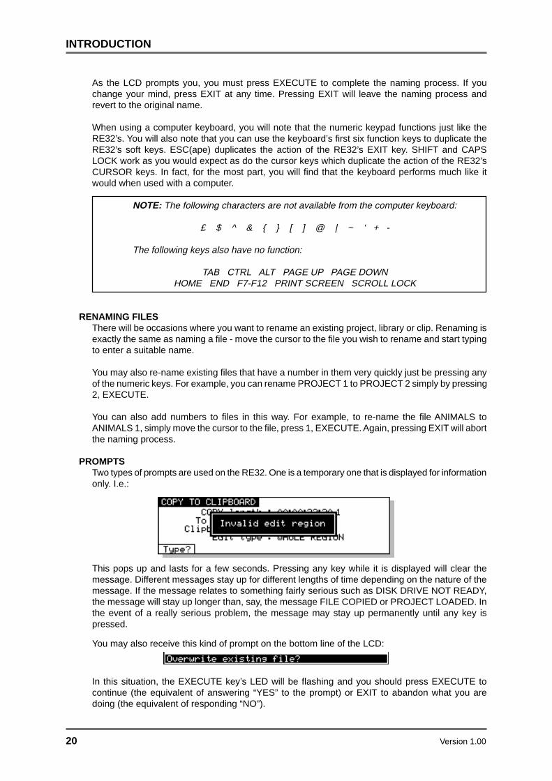
PROMPTSTwo types of prompts are used on the RE32. One is a temporary one that is displayed for informationonly. I.e.:
This pops up and lasts for a few seconds. Pressing any key while it is displayed will clear themessage. Different messages stay up for different lengths of time depending on the nature of themessage. If the message relates to something fairly serious such as DISK DRIVE NOT READY,the message will stay up longer than, say, the message FILE COPIED or PROJECT LOADED. Inthe event of a really serious problem, the message may stay up permanently until any key ispressed.
You may also receive this kind of prompt on the bottom line of the LCD:
In this situation, the EXECUTE key’s LED will be flashing and you should press EXECUTE tocontinue (the equivalent of answering “YES” to the prompt) or EXIT to abandon what you aredoing (the equivalent of responding “NO”).

Version 1.00 21
INTRODUCTION
GETTING AROUND A PROJECTThere are many convenient ways to move around the GRID.
TRANSPORT KEYSThe most obvious way, perhaps, is to use the REWIND and FAST FORWARD keys. Pressingeither or once will cause the project to rewind or fast forward at 10 x normal play speed andpressing it again will cause the project to rewind or fast forward at 100 x normal play speed.Pressing either of these keys again will revert to 10 x normal play speed.
During playback, simultaneously pressing PLAY ( ) plus either the or keys will allow you torewind or fast forward with ‘‘tape chatter’ and you will hear the audio rewinding or fast forwardingat high speed much like a normal MTR.
NOTE: When rewinding or fast forwarding with ‘chatter’, you may notice that some tracks willbe dropped. This is normal as the connected machines cannot play all tracks at high speed.However, if your project only has a few tracks to begin with, then this won’t be so noticeable.
LOCATE FUNCTIONAnother way to get around a project would be to set locate points using the STORE LOCATE keyand use the LOCATE key to locate directly to those points. 100 locate memories may be storedper project. You may also go to a timecode position directly by hitting LOCATE and typing in anappropriate timecode value.
You may also mark ‘grab markers’ using the GRAB function (SHIFT+STORE LOCATE). This will‘drop’ un-numbered markers along the scroll bar and these can be used as you like. You can marklocate memories and grab markers ‘on the fly’ as you are playing back (or indeed, jogging, spooling,even rewinding). 100 ‘grab’ markers can be set per project.
You can also use LOCATE with the IN, SYNC and OUT keys to go to these points.
You may also go to the start and end of a project using F5 and F6 in the GOTO LOCATE TIMEpage when you press the LOCATE key.
NEXT/PREVIOUS CUEBy pressing PREV Q (SHIFT+PLAY TO) or NEXT Q (SHIFT+PLAY FROM), you can go to the startand end of each cue in turn on the track(s) selected for edit. I.e.:
NOW
NOW
NOW
NOW
NEXT Q (SHIFT+PLAY TO) key
NEXT Q (SHIFT+PLAY TO) key
NEXT Q (SHIFT+PLAY TO) key
PREV Q (SHIFT+PLAY FROM) key
NOW
If a track is selected for edit, these keys take you to the start and end of each cue in turn on thattrack. If no tracks are selected for edit, they take you to the start and end of each cue on the tracksselected for playback (i.e. shown blue on the external monitor). If no tracks are selected for playbackor editing, these keys have no function.
22 Version 1.00
INTRODUCTION
JOG WHEELThe jog wheel allows you to ‘scrub’ audio much like reel-rocking on a conventional tape recorder.You may jog all tracks simultaneously. Normally, maximum jog speed is 1 x play speed but youmay set this to be as much as 5 x maximum play speed. More conveniently, perhaps, you can setit so that normal operation gives a maximum jog speed of 1 x play speed but, when the SHIFT keyis held, you can jog up to 5 x play speed.
The jog wheel can also act as a ‘spool’ function and the jog wheel then sets the speed and directionof playback. Maximum spool speed can be set to 5 x play speed.
You may also use the jog wheel to ‘scroll’ through a project very quickly. In this case, all you aredoing is ‘sliding’ the GRID on the VGA monitor, allowing you to get to points ‘off screen’ veryquickly. In this case, no audio is heard.
JOG, SPOOL and SCROLL are selected using the JOG/SPOOL key. This selects whether the jogwheel described below ‘scrubs’ audio, spools audio or scrolls through the project. When the JOGLED is on, the jog wheel will scrub audio. The jog wheel is always active, even in play, so that youcan just grab the jog wheel and start editing straight away.
When SPOOL is on, the jog wheel will spool audio.
When both LEDs are on, you can scroll through the project very quickly and no audio will be heardbut this does allow you to get to points in the project very quickly.
When both LEDs are off, the jog wheel has no function. This position is recommended whenmixing down so as to prevent accidental jogging during playback.
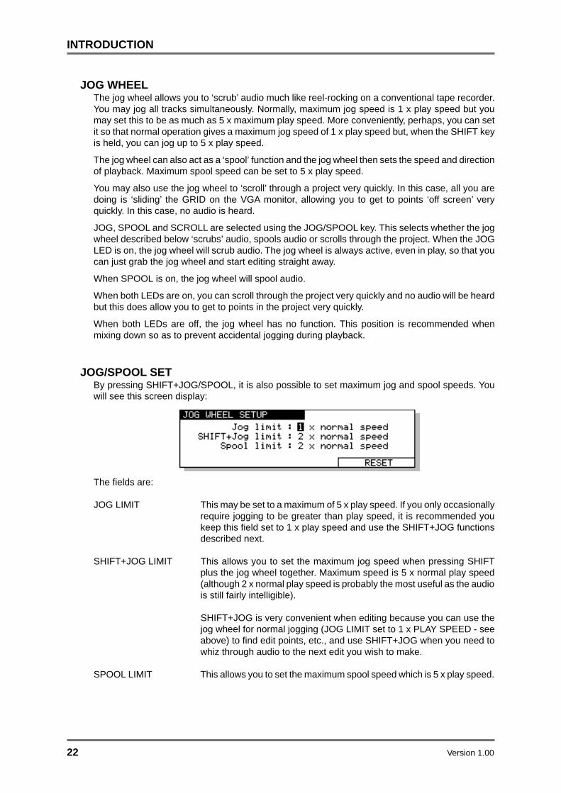
JOG/SPOOL SETBy pressing SHIFT+JOG/SPOOL, it is also possible to set maximum jog and spool speeds. Youwill see this screen display:
The fields are:
JOG LIMIT This may be set to a maximum of 5 x play speed. If you only occasionallyrequire jogging to be greater than play speed, it is recommended youkeep this field set to 1 x play speed and use the SHIFT+JOG functionsdescribed next.
SHIFT+JOG LIMIT This allows you to set the maximum jog speed when pressing SHIFTplus the jog wheel together. Maximum speed is 5 x normal play speed(although 2 x normal play speed is probably the most useful as the audiois still fairly intelligible).
SHIFT+JOG is very convenient when editing because you can use thejog wheel for normal jogging (JOG LIMIT set to 1 x PLAY SPEED - seeabove) to find edit points, etc., and use SHIFT+JOG when you need towhiz through audio to the next edit you wish to make.
SPOOL LIMIT This allows you to set the maximum spool speed which is 5 x play speed.
Version 1.00 23
INTRODUCTION
NOTE: When jogging or spooling at anything higher than nominal play speed, because ofrestrictions regarding disk speed and SCSI bandwidth, the connected machines willautomatically drop some tracks to allow the high speed playback. However, in most cases thisis fairly transparent and should not be particularly noticeable, especially on faster drives.
The RESET soft key on F5/F6 will reset the selections you make to their default value.
Press SHIFT plus the JOG/SPOOL key again or EXIT to leave this page.

24 Version 1.00
GETTING STARTED
GETTING STARTED - BASIC CONCEPTSAudio in the GRID is known as a CUE. A cue is a block of audio from start to finish. This may be araw recording in its entirety or may be the result of an edit. For example:
This shows two cues. On the monitor screen, the cues’ blocks are shown as blue and the waveforms(if selected to be displayed) are shown in grey.
NOTE: If the track is not selected for playback, the cue’s block is shown in a light grey and thewaveform in a slightly darker grey. I.e.
An EDIT REGION is the area that falls between the IN and the OUT times you have marked.
The IN and OUT markers are shown as vertical green lines. The edit region between the IN/OUTmarkers is highlighted green and the waveform (if selected to be displayed) is shown in black.
An edit area may exist across one or more cues (and across several tracks). For example:
It is also possible to select a single cue for editing using the SELECT Q key. I.e.
Once selected in this way, the cue may be subjected to all the usual editing possibilities. SELECTQ allows you to select a cue for editing very quickly without having to specifically mark an IN andan OUT time. Once a cue is selected in this way, it can be subjected to all the normal editingprocedures such as COPY, CUT and ERASE.
The basic operation is that you select a track (or tracks) for editing using the TRACK EDIT keyslocated along the top of the RE32’s panel. Once you have found the piece of audio you wish toedit, mark an IN time using the IN key located above the jog wheel. Now jog or play to where youwant the edit to end and mark an OUT time. Alternatively, line up the cue(s) you are interested inon the NOW time and press SELECT Q. Pressing the EDIT key will take you to the main edit pagewhere you may use any of the editing functions such as copy, cut, paste, insert etc..
CUE CUE
EDIT REGION
OUTIN
EDIT REGION
OUTIN
SELECT CUE

Version 1.00 25
GETTING STARTED
As a very simple example, imagine you wish chop out a cough from a vocal track on track 4. Selecttrack 4 for editing, play (or locate or fast forward/rewind or jog) to the start of the cough, jog over itto find an exact start point (you may also refer to the waveform shown on the monitor for extraassistance) and press the IN key. Now jog to the end of the cough and press the OUT key at anappropriate point. Pressing the EDIT key and selecting CUT will get rid of the cough and close thegap, shifting all subsequent audio backwards accordingly; pressing the EDIT key and selectingERASE will also get rid of the offending cough but will keep the gap created, thus preservingtiming. For example:
IN OUT
BEFORE CUT
AFTER CUT
IN OUT
IN OUT
BEFORE ERASE
AFTER ERASE
You may, of course, edit entire cues in this way. For example, let’s say you have a backing vocalyou wish to copy, select the track for editing, go to the cue, press SELECT Q followed by EDIT andCOPY. In this case, you have not needed to specifically mark IN and OUT times - simply selectingthe cue was sufficient. Multiple cues (across several tracks if necessary) may also be edited thisway. You may now locate to the point you want to place the copy and press PASTE or INSERT.
Of course, this is just a very simple example and there are many different ways the RE32 systemmay be used to edit and sync audio. However, whatever it is you are trying to achieve, you will findthat all functions are consistent, making operation easy and fast.

26 Version 1.00
GETTING STARTED
BASIC SYSTEM SETTINGSBefore we move on to look at basic operation, it is necessary to have a look at the SETUP pagesin order to set the system up as necessary. If you just want to get on with some recording, skip thissection and come back to it at a later date if you wish.
The SETUP pages allow you to set certain parameters that will affect either the RE32, an individualmachine or the system as a whole. These include setting sample rates, timecode types and inputs,external connections, etc. Once configured, your system settings can be saved so that you maypersonalise your operating system.
Pressing the SETUP key displays this screen:
The soft keys F1-F5 take you to the various setup menus. As there are more menus than soft keys,F6 is used as a “MORE” key to scroll through the list of menus in groups of five:
Many SETUP pages include a parameter in the top right hand corner labelled MACHINE. Thisallows you to select if parameter settings are applied to the system as a whole (MULTI) or to asingle machine (referred to as ID1, ID 2 etc..).
The MULTI SETUP pages are designed to allow easy configuration of parameters that should beset identically on each machine connected to the system.
Pressing RATES (F1) will take you to the SYSTEM RATES page:
This page is used to set the system’s global sample rate and frame rate.
The parameters are:
SAMPLE RATE This sets the system’s sample rate. You may select 32kHz, 44.056kHz,44.1kHz and 48kHz. Other options may be available depending on thefacilities available on the connected machines.
On entry to this page, if all connected machines are set to the samesample rate, then this rate will be displayed. If not, the sample rate fieldwill say “* DO NOT MATCH *” until a new rate is selected.

Version 1.00 27
GETTING STARTED
NOTE 1: This page will only allow selection of sample rates that are supported on all theconnected machines.
NOTE 2: Recordings made at a sample rate other than the selected sample rate will play backat the wrong speed. For example, if the sample rate is set to 44.1kHz and you try to play backa recording made at 48kHz, the recording will play back slow. Therefore, please make surethat your recordings are made at the correct sampling rate. Recordings made at differentsample rates cannot be used in the same project.
TC FRAME RATE This shows the system’s timecode rate.
This field is not editable, but instead serves as a visual check that allmachines are configured correctly. If all machines are set to the sameframe rate, then this rate will be displayed here. If not, this field will say“* DO NOT MATCH *”.
Timecode frame rates can be individually set on each machine asexplained later in the section on TIMECODE SETUP.
The SETUP page’s soft keys take you to other pages where certain parameters that affect thewhole unit may be set. Not all of these are relevant for basic operation so, for the moment, we willcontinue looking at other modes that are necessary for basic operation.

28 Version 1.00
GETTING STARTED
FORMATTING DISKSThe DISK pages are used for general disk management such as renaming and deleting files,formatting disks, copying disks, etc.. For the moment, we will just look at formatting a disk as thisneeds to be done before you can start working with the Akai system. Pressing DISK displays thisscreen:
Assuming you have not used the system yet, no files exist on disk and so the DISK page is empty.If this is your first time to use the system, you may receive the message:
This indicates that the disk needs formatting. Press F5/F6-DISK UTILS You will see this screen:
Press FORMAT (F6) to see this screen:
The FORMAT TYPE field is used to select the type of directory that will be created on the diskwhen it is formatted. The options now available are:
DD-PLUS This is the current Akai DD-series disk format which allows 4000 files tobe saved to a single disk and will give the best performance for real-timerecording and playback of audio.
MACINTOSH This allows the disk to be formatted in Macintosh HFS format. Note thatthis option will create a single volume, erasing all existing partitions onthe disk. If you want to create multiple partitions, it will be necessary touse a third-party Macintosh disk formatting application.
When the MACINTOSH format option is used, the disk may later beread on any Macintosh subject to the following limitations in variousversions of the Mac OS:
• System 7.1 can only support volumes up to a maximum size of 2gigabytes
• System 7.5 can recognise volumes up to a maximum size of 4gigabytes (which is currently the maximum size supported by Protoolsand many other products)
• System 7.5.3 and above can recognise volumes up to a maximumsize of 2 Terrabytes

Version 1.00 29
GETTING STARTED
NOTE 1: While the Akai machines can properly format a Macintosh hard disk or MO, it doesnot install any type of Macintosh driver software on the disk. Therefore, disks formatted on theAkai system will require third-party mounting software in order to appear on the Macintoshdesktop.
COMPATIBILITY NOTE: Disks made on any version of DD8, DD1500, or DR8/DR16 can beused with current software versions. However, please be aware that DD-PLUS formatteddisks cannot be used on previous versions or on other products that do not support thisformat.
You may select whether to just format the disk or format the disk and certify it afterwards. Formattingis very fast but if you select FORMAT & CERTIFY, this may take a while depending on the size ofthe disk. However, if this is the first time the disk is being formatted, it is recommended you run thecertify process as well. This will mark out any bad blocks on the disk and prevent them from beingused which will make the disk more reliable and not prone to read errors.
It is also possible to give the disk a name in the LABEL field. Here, you may enter a name of up toten characters. This name will accompany the disk wherever you take it. To label the disk, movethe cursor to the LABEL field and enter a name of up to ten characters using a PS/2 keyboardconnected to the RE32. Press RETURN (or EXECUTE) once to complete the name and a secondtime to enter it.
NOTE: Naming a disk is not compulsory! This is here entirely for your convenience.
Once you have set everything as you want, pressing FORMAT DISK will show this prompt.
To guard against accidental formatting, you must press SHIFT+EXECUTE simultaneously to initiatethe formatting. As you can see from the screens and the prompts, formatting will erase everything,erasing all files on it completely. BE VERY CAREFUL BEFORE PROCEEDING.
If you have external disk drives connected to the system, you may select which disk you wish toformat in the DISK field. PLEASE CHECK THE CORRECT DISK IS SELECTED.
The EXECUTE key will be flashing and you should select as appropriate. PressingSHIFT+EXECUTE will start the format process and pressing EXIT at this point allows you to cancel.
NOTE: Pressing SHIFT+EXECUTE now will start the format process and will wipe the disk. Bevery careful before proceeding as you could permanently erase important data. Once theformat process has begun, there is no going back!!!!

30 Version 1.00
GETTING STARTED
If you press SHIFT+EXECUTE, you will receive this screen:
If the disk is write protected, you will receive the prompt:
After a few seconds, the prompt will disappear and you will be returned to the main FORMAT DISKpage. You should eject the disk and take the write protect off. However, there may be a reason thedisk is write protected so it may be wise to leave the format page and check the contents beforeproceeding as there may be important data on it that needs to be kept.
NOTES ON FORMATTING DISKS
The full format and certify procedure takes between 20 minutes and an hour, depending on thesize of the disk. During this time, the system writes a new, empty directory to the disk afterwhich, if FORMAT & CERTIFY is selected as the format operation, it goes through the disksearching for bad blocks and marking them so that they won’t be used.
We recommend that you do a full format to prevent the possibility of disk errors later on.However, if you wish, you can either select FORMAT ONLY as the format operation of you canjust let the format run for 30 seconds or so (enough time to write the directory) and press EXITto abort. In most cases, FORMAT ONLY should be sufficient but please note that AKAIprofessional cannot accept responsibility for disks that have not been fully formatted that showerrors later on. It is recommended that you do a full format for brand new disks. If there are nobad blocks shown, there should be no need to do a full format again should you wish to re-format the disk for re-use at a later date.
As a final reminder...
FORMATTING THE DISK WILL ERASE THE CONTENTS COMPLETELY AND YOU WILLNOT BE ABLE TO RETRIEVE THEM.
We will come back to the other disk functions later as these are all to do with disk management(rename, delete, copy disks, etc.) and assumes there is audio on the disk. If this is the first timeyou have used the system, we need to get something onto disk before we can look at thesefunctions.
DD-PLUS DISK FORMATThe DD-PLUS disk format was introduced to replace the previous NORMAL and EXTENDEDformats. Current software no longer directly supports writing to NORMAL or EXTENDED formatdisks created on earlier versions of software. Although both these disk formats are still recognisedand fully supported for playback compatibility, any attempt to write to these disks will give an errormessage saying “Disk Format Is Read-Only!”. EXTENDED format disks can be easily updated toDD-PLUS format and is described later.
These are the basic settings one needs to make for operating the RE32 system. We will look atother DISK functions later on.

Version 1.00 31
GETTING STARTED
VGA SETUPThe SETUP key’s SHIFT function is VGA which allows you to setup various options related to theexternal display. When you press SHIFT+SETUP, the key’s LED will flash and you will receive thefollowing screen display:
The options are split across several pages. The first page shown above offers the following:
CUE INFORMATION Allows you to select:
CUE NAMES This will show the names of the current and,depending on the direction of playback/jogging/etc.,the next or previous cues will be listed for each trackdown the right of the GRID.
DISK IDS This will show the SCSI ID numbers of the disk drivesthe cues are playing from will be shown down theright of the GRID
DISK LABELS This will show the disk label given in the FORMATpage down the right of the GRID.
DISK NAMES This will show the name given to the disk in theFORMAT page down the right of the GRID.
CUE FADES These can be switched ON or OFF. Scrolling is slightly smoother withthe fades switched off.
CUE LEVELS It is possible to show the cue’s level with this option. The height of theblue box surrounding the waveform will vary according to its level(although this does have the effect of making the waveform display lookoff centre). CUE LEVEL may be switched ON or OFF.
WAVEFORMS You may select whether the cues’ envelopes are shown on the GRIDand the options are ON or OFF. You will note that scrolling is slightlysmoother with the waveforms switched OFF.
MAG You may set the vertical magnification of the waveform envelopes. Youmay also do the same thing at any time more conveniently by usingSHIFT+SCROLLVIEW.

32 Version 1.00
GETTING STARTED
Pressing the METERS key (F3/F4) will take you to the following page where you may set certainparameters relating to signal metering on the RE32’s external monitor screen:
The parameters are:
METER SOURCE Here you may select what will be displayed on the meters on the VGAmonitor. You may select INPUT LEVELS (to view the inputs to the tracksselected for record) or TRACK LEVELS (to show the level of the tracksplayback or record signals depending on the current auto-monitor status).
NOTE: Tracks must be selected for record before their signal INPUTLEVELS will be shown in the meters.
PEAK HOLD Here you can set the response of the VGA monitor’s meters when readingpeak levels. HOLD will keep the peak level permanently displayed untila higher peak level is received. You may also turn peak level detectionOFF if you wish.
Pressing CUES (F1/F2) will return you to the SHOW ON VGA MONITOR - CUES screen previouslydescribed. Selecting OPTIONS (F1/2) on the SHOW ON VGA MONITOR - CUES screen will takeyou to the next page shown below:
The parameters are:
EDIT AUTO ZOOM This function has three settings: OFF/MANUAL/AUTO.
With the parameter switched OFF, the vertical zoom in/out will zoom infrom 32 tracks through 24,16,12, 8, 4, 2 and finally 1 track shown on theVGA monitor.
When switched to MANUAL, as you zoom in/out, if certain tracks areselected for editing, the monitor will automatically show the selectedtracks as you zoom in. For example, if tracks 1, 2, 4 and 12 are selected,zooming in to eight tracks will show tracks, 1, 2, 3, 4, 5, 6, 7, 12; whenyou zoom in to four tracks, tracks 1, 2, 4 and 12 will be shown andzooming in to 2 tracks will, of course, show tracks 1 and 2. In manycases when editing, you want to zoom in on the tracks you are editing.
With this function switched to AUTO, as soon as you select a track forediting, the GRID will automatically zoom in to it. Any further tracksyou select for edit will be shown on the monitor. For example, if youselect track 3 for editing, the monitor will zoom in to one track, track 3.If you then select track 4, two tracks will be shown on the monitor,tracks 3 and 4. If you then select track 8, that too will be shown.

Version 1.00 33
GETTING STARTED
NOTE: When tracks are selected for edit, SHIFT+CURSOR UP/DOWN will toggle you betweenzooming in to the tracks selected for edit and the last selected vertical zoom level.
NOW POSITION You may set the vertical NOW marker anywhere on the GRID. 50% iscentral, lower percentages move it further to the left, higher percentagesto the right.
RULER You can select whether the ruler across the top of the GRID will be staticor will scroll with the project.
SCROLL DIRECTION You may set the direction in which the project scrolls. You may selectLEFT 5 RIGHT or LEFT 4 RIGHT - the arrow indicates the direction.
Pressing the MACHINES key (F1/F2) will take you to the final page shown below:
SHOW ON YGA MONITOR - MACHINESSHOW ON YGA MONITOR - MACHINES
OPTIONS DEFAULT
Machine Box:Machine Box:OFF
Information:Project NamesInformation:Project Names
Error Messages:OFFError Messages:OFF
The parameters are:
MACHINE BOX Switching this ON will force the machine box containing the CLIPBOARDDISPLAY and other information about the connected machines to bepermanently displayed on the right hand side of the GRID. When thisparameter is switched OFF, this box is only shown when single machineedit mode is selected as described later in the section on editing.
1 Project 1Project 1
CLIPBOARD
O: Sax stab
1: Gtr hook
2: Strings1
3:
4:
5:
6:
7:
8:
9:
STOP
The top line of this box shows the machine number, the name of theproject currently loaded on this machine and the current transport status(PLAY, STOP etc..)
The 4 symbol is shown alongside the currently selected machine.

34 Version 1.00
GETTING STARTED
INFORMATION This parameter selects whether the PROJECT NAME or MACHINE nameis shown in the area at the top of the machine box.
ERROR MESSAGES Here you can select to display system error messages in a large pop-upwindow on the VGA. In multi-machine systems, as well as showing thesystem error message, this window will indicate the machine number onwhich the error occurred.
In all SHOW pages, you may reset the parameters to their default settings using the DEFAULTSsoft key on F5/F6.
Press either EXIT or SHIFT+SETUP again to close this pages.

Version 1.00 35
RECORDING
RECORDINGIn the next few sections, we will see how to record and playback material as well as mark locatorsand locate to specific points in a project.
BASIC RECORDINGBefore we can do anything interesting with the RE32, we must first make a recording. Because theRE32 has many standard multi-track tape recorder (MTR) keys, recording is very simple. Thereare no special, separate record modes to encounter; simply select a track (or tracks) for recordand press PLAY and RECORD as you would on a normal MTR. There are other aspects to recordingbut we will look at those a bit later on.
To select tracks for recording, first switch off the ALL SAFE key if it is illuminated. This acts as amaster ‘record safe’ and prevents accidental recordings being made while it is enabled. Once theALL SAFE key is switched off, you may use any of the lower REC/EDIT keys to select a track (ortracks) for recording onto. When the track keys are selected, they will flash red indicating ‘recordready’. The monitor will show RECORD in red in the track status display area and record indicatorsare also shown under each associated meter.
Once you have made your selection, to record, simply press PLAY (to start playback) and thenpress PLAY and the red RECORD key together. The track key(s) will be steadily lit as will thetransport RECORD key. On the monitor, the recording will be shown as a red block as it is recording.
To stop recording, press STOP. After a second, the recording you have just made will be shown inblue (assuming the track is selected for playback otherwise it will be shown grey ) and the IN andthe OUT times will automatically be marked at the start and end of the new recording. The RECORDtrack select keys will flash indicating that you are back in ‘record ready’ state, ready to recordagain.
To drop out of record (i.e. stop recording but keep playing), simply press PLAY - the connectedmachines will drop out of record and keep playing.
NOTE: There is a minimum time before you can punch in to record again after punching outusing the STOP key. This is due to disk speed and will depend on the drive(s) you are using oneach machine. If you are using hard disks, you will find that you can punch back in to recordfaster than if you are using slower drives such as MO (Magneto Optical) drives.
It is also possible to start recording from stop by pressing the red REC key first and then pressingPLAY. You can stop recording by pressing PLAY again or by pressing STOP.

36 Version 1.00
RECORDING
When recording, you will see this screen:
As you are recording, so the RECORD TIME field ‘counts down’ as disk space is used up. In theevent of a mishap, you can abort the recording by pressing SHIFT and the red REC keysimultaneously. This will stop the recording process and delete it from disk, thereby saving diskspace and preventing the build up of unwanted recordings.
That really is all there is to do for simple recording - switch off ALL SAFE, select a track or tracks asappropriate, press PLAY and RECORD together, press STOP or PLAY to stop recording.
UNDOING A RECORDINGIf you don’t like the recording you just made, the simplest way to repair it is probably to record overit just like tape. It will recorded over in the GRID but, because all recording and editing is usuallynon-destructive, you can setup the connected machines so that the actual audio will still be on diskso you can retrieve it at a later date if necessary.
NOTE: When you make a recording, the IN and OUT times are automatically marked at thestart and end of the new recording. Because the AUTO-PUNCH function uses these times topunch in and out of recording automatically, if you wish to re-record over a recording you havejust made, to ensure punch-in and out are at exactly the same position, switch on the AUTO-PUNCH function (see below - AUTO PUNCH IN/OUT).
Another way out of a recording disaster is to undo the last recording you made using the UNDOkey. In fact, you could undo several of the recordings you have just made using the multi-levelUNDO function. The number of ‘levels’ of UNDO available depends on the connected machine(s):
Machine Number of UNDO levelsDD8 (16-bit) 4DD8 (24-bit) 20
DR16pro 4DD1500 20
Of course, should you change your mind, you can REDO the recording using SHIFT+UNDO (REDO).Not only can you use UNDO to repair mistakes you may have made but you could also use it tocompare recordings. For example, you might make a recording that you think is acceptable but itcould be improved upon so you re-record over it. After the second recording, you can use theUNDO function to compare the two. Being a multi-level undo, you could do this several times,making several recordings and then comparing them using UNDO and REDO, keeping the oneyou like best.

Version 1.00 37
RECORDING
ADVANCED RECORDINGThere is no ‘advanced recording’ mode as such - this section just tells you more about the recordingfunctions.
Recording is designed to be as simple as possible and you may, if you wish, make a recording asdescribed above. However, it is also possible to name recordings although recordings are given adefault name so that you may avoid this process if you just want to get on with the job and therecording can be renamed afterwards. There are other parameters associated with recording whichcan set if you wish.
When you switch off the ALL SAFE key, you will see this screen:
The fields on this screen are:
RECORDING NAME Here, you may name the recording you are about to make by typing asuitable name of up to ten characters on a PS/2 keyboard connected tothe RE32. Press RETURN to complete the naming process.
NOTE: The Akai DD/DR-Series of disk recorders have an ‘auto-increment’ function for namesand so each new recording you make will have a new name based on the ‘seed’ name yougive it here. For example, if you name a recording GUITAR, all subsequent recordings youmake will be automatically named GUITAR 1, GUITAR 2, etc., until you specify a new ‘seed’name in this field
The autoname function does not work when performing a punch-out followed by a punch-in. Inthis case, both recordings will have the same name. This is not a problem because recordingscan have the same name in a project. Recordings can be renamed afterwards if you wish.
RECORD MODE In this field, you may select how the recordings you are about to makeare stored in the project.
The default setting is PROJECT ONLY. With this selection, newrecordings will be placed only into the currently active project. Thisselection is non-destructive - each time a new recording is made, existingfiles on disk from previous recordings will be unaffected.
You may also select DESTRUCTIVE. This is a special type of recordmode that behaves more like traditional tape.
As mentioned, recording is non-destructive by default but, sometimeswhen recording, it is possible to build up a lot of redundant audio on yourdisk, especially if you are dropping in and out over the same point timeand time again (for example, when recording vocals). As a result, yourdisk can soon become full of audio you cannot access or use. TheDESTRUCTIVE record mode goes some way to overcome this.

38 Version 1.00
RECORDING
When DESTRUCTIVE recording mode is on, if you record over existingcues, the audio associated with the original cue may be erased fromdisk. However, you must either record over the original cue completely,or start recording from within a cue to past its end - dropping in and/orout half way through the cue will not cause the original cue’s audio to bedeleted from disk. For example:
DROP IN DROP OUT
DROP IN DROP OUT
DROP IN DROP OUT
DROP IN DROP OUT
DROP IN DROP OUT
Will not erase original
Will not erase original
Will erase the region of the original recording between the DROP IN and DROP OUT points.
Will erase original
Will erase original
New recording
New recording
New recording
New recording
New recording
If you are using AUTO-PUNCH to drop in and out of record automaticallyand you have to keep repeating the auto-punch over and over again, theDESTRUCTIVE mode will be useful as it will help prevent the build up ofunwanted recordings on your disk.
NOTE: There are certain considerations regarding destructive recording that you should beaware of.
• THERE IS NO UNDO FOR RECORDINGS WHEN DESTRUCTIVE MODE IS USED.
• After you have just loaded a new project, as a safety factor, recording over cues in thatproject will not delete their audio from disk and the original project cannot be damaged. If,however, you record over cues recorded since the project was loaded, newly recordedcues’ audio will be deleted from disk.
The destructive record mode will go some way to avoiding the build upof unnecessary audio on your disk especially when performing multiplepunch-in/out but, given the above points, there may be times when youwill need to perform a manual cleanup or minimise.

Version 1.00 39
RECORDING
** WARNING **
BECAUSE OF THE DESTRUCTIVE NATURE OF THIS FUNCTION, PLEASE MAKESURE IT IS NOT INADVERTENTLY SELECTED WHEN RECORDING AS YOU RUN THE
RISK OF LOSING VALUABLE DATA.
For example, if you are used to using non-destructive recording but receive a disk whereDESTRUCTIVE record mode is enabled, you may be working in your usual way, thinkingthat new recordings are recoverable when, in fact, they are being deleted from disk everytime you record over them. A good example may be where you are repeatedly dropping in
over dialogue recordings, unaware that DESTRUCTIVE mode is set. You may think that youcan retrieve ‘out-takes’ after the artist has left only to find that only the very latest recordings
you made are available on disk. In this case, before recording over existing cues, pleasecheck that DESTRUCTIVE record mode has not been selected.
** THERE IS NO UNDO WHEN DESTRUCTIVE RECORD IS USED **

40 Version 1.00
RECORDING
RECORD DISKSBy default, all audio will be recorded onto the same disk as the current project. In a larger system,you may have other drives to extend the recording time. However, please note that recording to anexternal drive could cause playback problems later on.
For example, in the case where you are playing back a project from an MO disk in Drive SCSI ID0 but, for some reason, you record to a hard disk on SCSI ID 1, if the MO is removed and playedback on another system, because some audio has been recorded on the other system’s hard disk,that audio will not play. The cue will be shown bright yellow in this case indicating that although thecue is in the project, the audio is not on the selected disk. If you do record to an external disk,ensure that this disk accompanies the project disk.
Pressing DISK (F1) in the main record page take you to the RECORD DISKS page where you canselect the drive each machine will use for recording onto:
The fields on this screen are:
TRACKS This is where you select the machine for which you want to select arecord disk. To avoid confusion, the machines are listed by the tracksthey represent. For example, machine 1 may be shown as “1-16”,machine 2 as “17-32” etc..
RECORD DISK Here you may select which disk to record onto (assuming you havemore than one drive attached to the system).
FREE ON DISK In this field, you can see how much time you have free on the currentlyselected disk. This field is not accessible and is shown for information.
You will note that as you select more tracks for recording, so the amountshown in the FREE ON DISK field changes. For example, if you have 12minutes free on disk, when you select one track for record, that timeremains unchanged. If, however, you select two tracks for record, thatfigure will halve, informing you have 6 minutes. Should you select anothertrack, it will show that only 4 minutes is available.
Of course, you still have 12 minutes available in total but this availabletime is divided by the number of tracks you have selected. For example,in this case, when two tracks are selected, you still have 12 minutes freeon disk but, because you are making two recordings you may only recordfor a total of six minutes.

Version 1.00 41
RECORDING
RECORD TYPEThe type of file that is created on the disk for each new recording may vary depending on theformat of the selected record disk and the user’s choice of bit resolution. Pressing TYPE (F2) inthe main record page take you to the RECORD TYPE page shown below:
The options on this screen are:
TRACKS This is where you select the machine for which you want to select arecord file type. To avoid confusion, the machines are listed by the tracksthey represent. For example, machine 1 may be shown as “1-16”,machine 2 as “17-32” etc..
FILE TYPE This selects the type of audio file that will be created when new recordingsare made. The options available in this field depend on the format of theselected Record Disk.
• AKAI: This is the DD’s native audio file format and is only availablewhen the selected Record Disk is an AKAI format
• AIFF:This is Apple’s “Audio Interchange File Format” that is used bymany Macintosh software applications. The AIFF option is onlyavailable when the selected Record Disk is Macintosh format.
• SD-II: This is the native audio file format used by Digidesign ProTools and some other Macintosh software applications. The SD-IIoption is only available when the selected Record Disk is Macintoshformat
• AKAI->FAIRLIGHT: This allows special Akai audio files to be createdwhich are intended for playback on a Fairlight MFX3plus system fittedwith Akai File Exchange support. This option is only available whenthe selected Record Disk is an AKAI format
NOTE: Some of these file type options may not be available depending on the facilities availableon the selected machine. Please refer to the section on DISK COMPATIBILITY for furtherinformation about recording to non-AKAI disks.

42 Version 1.00
RECORDING
BIT LENGTH This selects the audio bit length for new recordings.
• 16-bit: This is the compact Disc standard.
• 20-bit: This option allows 20-bit audio to be recorded, giving greaterresolution and headroom.
• 24-bit: This option allows 24-bit audio to be recorded, giving evengreater resolution and headroom.
• 20-bit (packed): This is a special option that is only available whenrecording AKAI format audio files. Typically, 20-bit audio occupiesthe same space on disk as 24-bit audio (the extra 4-bits of storagespace in each sample being wasted). The 20-bit ‘packed’ mode avoidsthis waste of space by writing the audio to disk in a special pattern.
Sample 3Sample 1 Sample 2
Sample 3Sample 1 Sample 2
Sample 3Sample 1 Sample 2
24-BIT :
20-BIT :
20-BIT PACKED :
Note that this mode does not involve any ‘audio compression’. It justplaces the data on disk in an optimal manner to maximise disk storagespace and bandwidth.

Version 1.00 43
RECORDING
RECORD SETUPIt is possible to select certain other options relating to recording in the RECORD SETUP page.This is accessed by pressing SETUP (F3/F4) from the main record page:
The parameters are:
CROSSFADE This allows a record crossfade of 0 to 80ms to be set.
AUTO MONITOR Here you may select how you will monitor the input signal. The defaultselection is RECORD AND STOP. With this selected, you will hear theinput signal under the following conditions:
HEAR INPUT?RECORDSTOP PLAYBACK
YES NOYES
RECORD TRACK'S PLAY SELECT KEY ON
RECORDSTOP PLAYBACKYESYES
RECORD TRACK'S PLAY SELECT KEY OFF
YESHEAR INPUT?
The other selection you may make is RECORD ONLY. With this selected,you will only hear the input signal whilst actually recording, regardless ofthe status of the record track’s PLAY select key. I.e.:
RECORDSTOP PLAYBACKYESNO
RECORD TRACK'S PLAY SELECT KEY ON OR OFF
NOHEAR INPUT?
RECORD ONLY is useful when you only ever want to hear the inputsignal during record and at no other time. The system will take care ofthe switching automatically.
RECORD MODE This is a duplicate of the same parameter on the main record page whichallows you to select how the recordings you are about to make are storedin the project.

44 Version 1.00
RECORDING
PUNCH MODE This selects how the system will respond if the record track selectionsare changed while the transport is in record.
Available selections are :
NORMAL This is the default setting. The record track selections can not be changedwhile the transport is in record.
TRACK KEYS In this mode, the transport responds in the same manner as aconventional MTR. Pressing the REC and PLAY keys will put the systeminto a ‘record-ready’ condition waiting for tracks to be punched in fromthe track select keys. If no tracks are selected at the time the REC andPLAY keys are pressed, the REC key will flash. In this condition, whenany of the track select keys are pressed the system will punch into recordon the selected track(s) and the REC key will light steadily. When a trackselect key is pressed again, that track will be punched out of record.
PRIMED In this mode, recording will start immediately on selected tracks whenthe REC and PLAY keys are first pressed. After this, if new record tracksare selected, the appropriate track select key(s) will flash indicating thatthe track is in ‘record-ready’, but recording will not actually start until thePLAY key is pressed again while holding down the REC key. While inrecord, pressing the track select key of a track that is actually recordingwill punch that track out of record and back into the ‘record-ready’ state.
NOTE: The TRACK KEYS and PRIMED punch modes are only available on 8 track machines(e.g. DD8, DD8plus). The PUNCH MODE parameter is not shown on this screen if othermachines are being used in the system.
Press EXIT at any time to leave this page and return to the main RECORD screen.

Version 1.00 45
RECORDING
** NOTES REGARDING TRACK MONITORING DURING RECORDING **
On analogue multi-track tape recorders, we take seamless punch-in/out for granted. However,this is much more difficult to achieve on hard disk recorders.
The Akai DD/DR-Series have seamless punch-in/out and to achieve this, they play previouslyrecorded material in the background so that, when you punch-out manually, the track is readyto play back immediately with no gap at the punch-out. I.e.:
PUNCH-IN PUNCH-OUT
PLAY PLAYMUTED
ORIGINAL RECORDING
NEW RECORDING
This means that in most cases, the system will drop in and out of record pretty much like anormal MTR. Usually, on most hard disk recorders, due to disk speed restrictions and SCSIbandwidth, there is a gap of several seconds or more at the point of drop-out. This is not so onthe Akai system and it is possible to punch in and out seamlessly on mono and stereo tracks.
However, in order to achieve this, it is necessary to drop tracks because, during recording, thetrack selected for recording is actually using two tracks - one for the actual recording and theother for the muted track. The Akai DD/DR-Series machines deal with this in a way so that thisshould not be much of a problem and the way this works is designed to be as transparent aspossible. When you enable a track for record, the priority for track dropping is:
FIRST TRACK(S) TO BE DROPPED - Those with no audio on them.
NEXT TRACKS TO BE DROPPED - Any tracks not selected for playback.
NEXT TRACK(S) TO BE DROPPED - Those with the least audio on them (i.e. a track with oneor two cues will be dropped before a very busy one).
In normal practice, you should find the process fairly transparent and it’s only in very busyprojects with a lot of cues across all tracks that you will hear the track dropping take place.
However, when using an MO, because these are slower than hard disks, you may noticetracks dropping. Also, when recording four tracks, there may be gap in monitoring when youdrop out of record. The actual recording will be fine - only the monitoring at the point of punch-out will be momentarily affected.
As mentioned, though, under normal circumstances, when recording stereo or mono cuesonto either a hard disk or MO, you should not notice this.
46 Version 1.00
RECORDING
AUTO PUNCH-IN/OUTSo far, we have seen how to drop in and out of record manually. It is also possible to automate thisusing the AUTO-PUNCH key .
The AUTO IN and OUT times are set using the IN and OUT keys. Switching AUTO-PUNCH to ON(i.e. LED lit) will activate the auto punch-in/out function.
To use the AUTO function, locate to a point before the IN time, select a track (or tracks) for recordand press PLAY and RECORD together. The RECORD track select key will flash as will the transportkeys’ REC key as the connected machine(s) play up to the IN time. When the IN time is reached,they will automatically drop in to record and will drop out when the OUT time is reached.
NOTE: One feature of the RE32 is that, because the IN and OUT times are automaticallymarked at the start and end of a new recording, once you have performed a recording manually,to re-create that time and time again (for example, if you need to keep re-taking the samerecording over and over again), you can simply switch AUTO -PUNCH on and the system willthen repeatedly punch-in and out automatically at those points.
If the DESTRUCTIVE mode of recording is enabled under these circumstances, old recordingswill automatically be deleted from the disk thus preventing the build up of unwanted, uselessrecordings.
REHEARSEWhen the REHEARSE key is switched on, the RE32 will ‘pretend’ to punch in and out but no audiowill be recorded allowing you to rehearse a punch in/out prior to actually doing it.

Version 1.00 47
INPUT ROUTING
INPUT ROUTING - ASSIGNING INPUTS TO TRACKSDepending on the specification of the machines in the system, there may be more tracks thanthere are inputs so some way of assigning the inputs to tracks is needed. This is achieved from theROUTE INPUTS page which is accessed by pressing F5/F6 (ROUTE INPUTS) on the main recordpage.
The first screen shown allows you to select the machine for which you would like to configure theinput assignments:
Select the required machine using the DATA ENTRY +/- keys. As you select each machine, thedisplay will show the track numbers assigned to that machine to avoid any confusion.
Pressing the EXECUTE will take you to the main routing assignment page. This will vary dependingon the type of machine selected.

48 Version 1.00
INPUT ROUTING
INPUT ROUTING - DR16proWhen a DR16pro is selected on entry to the ROUTE INPUTS pages, the following screen will beshown:
This shows the default routing in a system with analogue inputs selected. If the DR16pro has anoptional multi-channel digital interface installed (AES/EBU or ADAT), you can select betweenANALOGUE or DIGITAL inputs 1..8 using the DATA ENTRY +/- keys when the cursor is over theINPUT TYPE field.
Inputs may also be routed to tracks using the cursor up/down/left/right keys to move to a matrixpoint. You then use the DATA ENTRY +/- keys to assign or de-assign accordingly. For example, toroute the right channel of the DR16pro’s built-in stereo digital interface (DINR) to track 6, move thecursor to 6 using the cursor right key and use the cursor down key to select DINR. The cursorlooks like this and shows you where you are.
The cursor is shown and the track number is highlighted.
To route this input to the selected track, press the DATA ENTRY+ key. You will see this screen:
This shows that DINR is now routed to tracks 6.
To route inputs to tracks 9..16, use the SCROLL VIEW keys to view tracks 9..16.
The RESET (F6) key may be used to restore the default routing (input 1 goes to track 1, input 2goes to track 2 etc..).

Version 1.00 49
INPUT ROUTING
INPUT ROUTING - DD8 (or DD8plus)
When a DD8 (or DD8plus) is selected on entry to the ROUTE INPUTS pages, the screen willchange to allow control of the input architecture on these machines:
This shows the default routing in a system with analogue inputs. When the cursor is over theINPUT TYPE field, you can select between ANALOGUE or DIGITAL inputs using the DATA ENTRY+/- keys.
Inputs may also be routed to tracks using the cursor up/down/left/right keys to move to a matrixpoint. You then use the DATA ENTRY +/- keys to assign or de-assign accordingly. For example, toroute INPUT 3 to track 6, move the cursor to 6 using the cursor right key and use the cursor downkey to select INPUT 3. The cursor looks like this and shows you where you are. To the right of thescreen, the input you have selected and the track you are on is also shown.
The cursor is shown and the track number is highlighted. The selected track and input are alsoshown to the right of the screen - in this case, TRACK 6 INPUT 3. To route this input to the selectedtrack, press the DATA ENTRY+ key. You will see this screen:
INPUTS
IN 1/2IN 3/4IN 5/6IN 7/8
Input type : ANALOG
Track6
Input3
RESET
1 2 4 5 7 83 6
This shows that INPUT 3 is now routed to tracks 3 and 6.
The RESET (F6) key may be used to restore the default routing (input 1 goes to track 1, input 2goes to track 2 etc..).

50 Version 1.00
INPUT ROUTING
INPUT ROUTING - DD1500
The selection of input routing options on the DD1500 depends very much on the options you haveinstalled in the system. In a basic system with no ADCs connected (I.e. the only inputs you haveare the digital inputs A and B), the default assignment would be:
DIGI A L/RDIGI B L/R
13
24
57
68
911
1012
1315
1416
TO TRACKSINPUTS
If you add one DD1500a to the system with just two stereo analogue inputs, these would beautomatically assigned as
1234
5678
9101112
13141516
TO TRACKSINPUTSADC 1LADC 1RADC 2LADC 2R
The digital inputs A and B may also be assigned if you wish but, in this case, the analogue inputswould take priority in the routing.
Of course, should you add more inputs (be they digital or analogue), the system will assign themautomatically for you but you may re-assign them as you wish.
With this default setting, you may record using a normal 4- or 8-group output track laying mixerand assign mixer channels to tracks from the mixer just as you would with a normal MTR with noneed to worry about having to set any special input routing. However, if you do wish to route inputswithin the DD1500, this is also possible.
When a DD1500 is selected on entry to the ROUTE INPUTS pages, the screen will displaysomething like this:
This shows the default routing in a system with no analogue inputs, only the standard digital inputsA and B.
This shows the default settings for a system fitted with a DD1500a comprising one AD4 analogueinput board.

Version 1.00 51
INPUT ROUTING
Inputs can be assigned to tracks 9..16 by pressing the SCROLL VIEW key. You will see this screendisplay:
This shows the default assignment for a system with eight analogue inputs with each input beingrouted to tracks 9..16.
With the cursor to the far left of the screen in the INPUTS column, you may assign inputs to tracksusing the DATA ENTRY +/- keys. For example, to assign digital input A to tracks 1 and 2 instead ofthe analogue inputs shown here, press the DATA ENTRY+ key to receive this display:
Any pair of inputs can be assigned to tracks in this way.
Inputs may also be routed to tracks using the cursor up/down/left/right keys to move to a matrixpoint. You then use the DATA ENTRY +/- keys to assign or de-assign accordingly. For example, toroute ADC 1R to track 6, move the cursor to 6 using the cursor right key and use the cursor downkey to select INPUT ADC 1R. The cursor looks like this and shows you where you are. To theright of the screen, the input you have selected and the track you are on is also shown.
The cursor is shown and the track number is highlighted. The selected track and input are alsoshown to the right of the screen - in this case, TRACK 6 INPUT ADC 1R. To route this input to theselected track, press the DATA ENTRY+ key. You will see this screen:
This shows that INPUT ADC 1R is now routed to tracks 2 and 6.
Any combination of inputs may be routed to tracks in this way (although two inputs may not berouted to one track). Don’t forget that to route inputs to tracks 9-16, you should SCROLL VIEWkeys.

52 Version 1.00
INPUT ROUTING
Should you wish to reset the input routing to the default setting, press the RESET key. The inputselection and track routings you make can be saved as part of the system settings when you savethem (see SYSTEM - SETTINGS).
Of course, depending on your system, you may have more or less analogue and/or digital inputs.The procedure is exactly the same, however, regardless of system configurations.
RECORDING DIGITALLYWhen recording digitally, the machine must synchronise to that digital audio signal’s wordclock. Ifyou have selected a digital input to record through in the ROUTE INPUT page, the input willusually be selected automatically as the wordclock source by the machine as soon as you selecta track routed to that input for record.
If, for some reason, you select to record digitally but a digital input is not connected, as soon asyou try to select a track (or tracks) for record, you will get the prompt:
You will not be able to select any tracks for record until the problem has been fixed. Please checkyour digital audio connections.
This message will also be shown if the digital audio signal gets disconnected or you select anotherdigital input that has no connection.
If you are in the process of recording when this happens, the system will stop recording andplayback. Please check your connections.

Version 1.00 53
PLAYBACK
PLAYING BACK AUDIO MATERIALThere really isn’t much to say about playing audio - simply press the PLAY key!! Of course, in orderto hear anything, you must select tracks for playback using the TRACK SELECT PLAY keys at thetop of the RE32’s panel. When tracks are selected for play (i.e. their keys are lit), audio is shown inblue blocks on the monitor with a grey waveform. If a track is not selected for play (the keys are notlit), the monitor will display them as light grey blocks with slightly darker grey waveforms. In manyways, operation is much the same as for any standard MTR with the added bonus of a scrolling‘track sheet’ on the external monitor.
The RE32’s transport keys are designed to emulate those on an MTR as closely as possible. Thekeys are:
This is the PLAY key.
This is the STOP key and will stop playback, recording, rewind and fastforward.
This is fast forward. Pressing it once gives x 10 play speed; pressing itagain gives x 100 play speed. Press it again to fast forward at x 10 playspeed.
When is pressed during play, the system will fast forward with ‘tapechatter’ just like a standard MTR. In this case, only x 5 play speed ispossible.
This is rewind. Pressing it once gives x 10 play speed; pressing it againgives x 100 play speed. Press it again to fast forward at x 10 play speed.
When is pressed during play, the system will rewind with ‘tape chatter’just like a standard MTR. In this case, only x 5 play speed is possible.
REC This key allows you to drop in and out of record just like a normal MTR.Press plus REC together to drop in and press (or ) to drop out ofrecord. Of course, in order to record, you must first select tracks to recordusing the RECORD select keys on the upper panel.
The RE32 offers other play options not available on most tape machines or hard disk recorders,however.
For example, there is REVERSE PLAY. Pressing SHIFT+PLAY will cause the system to playbackwards. This is a technique used a lot in film applications where mixing engineers actually mixdown backwards in order to save time. However, please note that you cannot record backwards.
Above the main play keys is a row of special play keys. These are:
PLAY TO This will play up to the NOW time. I.e.:
PLAY TONOW
This is useful for checking things prior to editing (i.e. to find a good editpoint) but may also be used for checking things on the NOW timegenerally.

54 Version 1.00
PLAYBACK
The default PLAY TO time is 1 second but you may change this bypressing SHIFT+PREROLL to go to the PREROLL SETUP page andthen PLAY TIMES (F1/F2) to go to this screen:
You may set the PLAY TO duration to a maximum time of 9 seconds. Asthis function is used almost exclusively for quick auditioning, times inexcess of this are considered unnecessary.
You can also set the PLAY FROM duration here as well You may resetthe play durations to the default settings of 1 second by pressing RESET(F5/F6).
PLAY FROM This plays from the NOW time for a specified duration. I.e.:
PLAY FROM
NOW
The PLAY FROM duration can be set by pressing SHIFT-PREROLL asabove (setting PLAY TO).
NOTE: You will find that if PLAY durations are set longer than the default 1 second setting,play response will be marginally slower.
PLAY IN>OUT This will play from the IN point to the OUT point. I.e.:
IN OUTPLAY IN>OUT
This is useful for checking edits but can also be used for checking thelast recording you made. Because the RE32 automatically places the INand OUT times at the start and end of a new recording, you may usePLAY IN>OUT to check it immediately after recording.
You will find these keys very useful for checking things. With their default values of 1 second, theirplay response time is very fast indeed making auditioning and checking very quick and convenient.

Version 1.00 55
PLAYBACK
The final three keys in the transport section are:
LOCATE This is used to locate to new positions in the GRID. It is described laterin the LOCATOR section.
STORE LOCATE This is used to store locate times. It is described later in the LOCATORsection.
INPUT MON This key causes all tracks which are armed for recording to temporarilyswitch to monitor their input source. Usually, the system’s auto-monitorfunction causes playback audio to be heard while the transport is inmotion and any armed record inputs to be heard while the transport isstopped or recording. This key temporarily overrides this switching sothat the input audio can be heard at any time.
MUTING TRACKSTracks are muted simply by turning the appropriate PLAY track select keys off. When muted, thecues are shown in grey on the external monitor.
SOLOING A TRACKThere is no dedicated SOLO key on the RE32. This is not an oversight on our part as the samething can be achieved using ALL PB and ALL MUTE. To solo a track, press ALL MUTE (SHIFT+ALLPB) and select the track(s) you wish to solo. To ‘un-solo’ the track(s), press ALL PB.

56 Version 1.00
PLAYBACK
GROUPING TRACKSIt is also possible to group up to ten different combinations of tracks together. Actually, this is notspecifically a playback feature because you may also group tracks together for record and/or edit.
To store a group, assuming you have selected tracks as necessary, press the GROUP STOREkey (SHIFT+GROUP). The following screen will be shown:
The parameters on this screen are:
MEMORY This allows you to select which GROUP memory you want to store (0..9).
PLAY SELECTS When set to YES, this allows the current play track selects to be storedin the GROUP memory.
EDIT SELECTS When set to YES, this allows the current edit track selects to be storedin the GROUP memory.
RECORD SELECTS When set to YES, this allows the current record track selects to be storedin the GROUP memory.
After selecting the GROUP memory and the appropriate tracks for play, record or edit press theEXECUTE key to save the selections.
Groups are recalled simply by pressing the GROUP key to select the GROUP RECALL screenand selecting the required group memory
.
The GROUP keys are very useful for storing combinations of PLAY and RECORD. They are alsoparticularly useful when editing, especially when copying awkward track combinations from one toanother (for example, tracks 1, 3, 6 to tracks 2, 7, 8).

Version 1.00 57
AUTOLOCATOR
AUTOLOCATORHowever, you often need to go to very specific points in a project. To facilitate this, the RE32 hasa powerful autolocator that allows you to store up to 100 numbered locate memories, 100 ‘grab’markers as well as being able to locate to the start, the end and the IN, SYNC and OUT points. Youmay also locate to the next and previous cues and you may also locate directly to timecode values.Pressing the LOCATE key will display this screen:
LOCATING TO THE START OR END OF A PROJECTTo locate to the START or END of a project, simply press LOCATE, START (F5) or LOCATE, END(F6) and you will taken directly to these positions. You can also locate to the START of a project bypressing SHIFT + , or to the END of a project by pressing SHIFT + .
LOCATING TO THE NEXT OR PREVIOUS CUESYou may also go sequentially to the start and end of the previous or next cues by pressing PREVQ (SHIFT+PLAY TO) or NEXT Q (SHIFT+PLAY FROM).
The logic for cue selection is that you will only go to the cues on the tracks selected for edit. If onlyone track is selected for edit, you will only go to the cues on that track. If one or more tracks areselected for edit, you will go to each one on each track in turn. If no tracks are selected for edit,only PLAY, you will go to every cue on all tracks in turn. If no tracks are selected for PLAY (i.e. alltrack select keys are off), the function does not work.
LOCATING TO TIMECODE POSITIONSYou may locate to a timecode position using the numeric keypad. For example, to locate to01:12:13:23, press LOCATE, 1,00,12,00,13,00,23,00, ENT where 00 is the ‘double zero’ key onthe keypad.
NOTE: If you previously located to a locator memory number, you may have to press F1 toselect TIME.
LOCATING TO LOCATOR MEMORIESTo locate to a previously stored locate memory, press LOCATE, F2 (MEMORY) and the appropriatenumber 0-99 on the keypad followed by ENT or EXECUTE (see STORING LOCATE MEMORIES).
Locate points are unique to a project and all locator memories are saved when you save theproject and are recalled when the project is subsequently re-loaded.
STORING LOCATE MEMORIESTo store locate memories, press STORE. You will see this screen:
The STORE TIME field shows the current NOW time when you enter this page. However, bypressing F2 - TIME - you may change this time here prior to storing it but this will not affect yourposition and you will stay on the current NOW time. For example, if you know you want to store00:05:00:00.0 in a locator memory, you may enter this value here without moving from the currentNOW time.

58 Version 1.00
AUTOLOCATOR
There are actually two ways to store locate memories. One allows you to store single memoriesand leave the page, the other allows you to stay in the page and store multiple locate memorieswithout having to keep re-entering the STORE page.
To store a single memory, locate to the time you want to store using LOCATE, TIME and thenpress STORE, type in a locate memory 0-99 from the keypad and press ENT or EXECUTE.
To store multiple locate memories, enter the STORE page and enter the first memory number 0-99you want to store and then press STORE NEXT (F5/6). The memory will be stored and TO LOCATORMEMORY number will automatically be incremented to the next number so you can store the nextnumber simply by pressing STORE NEXT again. This allows you to store locate positions ‘on thefly’ during playback. For example, with this page open and select a suitable memory location. Nowstart playback and, while playing back, pressing STORE NEXT will store the memory locationsincrementally. You may also do this whilst jogging or using the NEXT/PREV CUE functions, etc..Pressing EXIT or EXECUTE will close this screen and return you to the main screen.
When you store locate memories, they are shown on the scroll bar beneath the GRID as a whitetriangle:
You may also mark locate points using the GRAB key. Simply pressing the GRAB key will mark agrabbed locate point and it will be shown as a grey vertical line in the scroll bar beneath the GRID:
You may ‘grab’ the points at any time when the system is stopped or, in fact, when playing back.These markers are particularly useful for marking locate points of interest you may wish to comeback to later (for example, sections in a piece of music, mistakes in a vocal track, etc.) and up to100 grab points may be marked in one project. They can be converted to locate memories simplyby locating to them (holding down GOTO plus the numeric keypad’s -/< or +/> key) and thenstoring a locate memory as described above.
When this page is open, pressing EXIT will return you to the main work page.
CLEARING LOCATE MEMORIESSometimes, it may be necessary to clear (delete) one or more (or all) locator memories. There isno real benefit to this other than reducing clutter in the scroll bar by removing locate memories thatare no longer required.
CLEARING SINGLE LOCATE MEMORIESTo clear a single locate memory, press SHIFT+GOTO(STORE), select the locator memory youwish to clear and press F3/F4 - CLEAR. If you make a mistake, simply press STORE again to re-mark it.
CLEARING ALL LOCATE MEMORIESTo clear all locate memories, press SHIFT+STORE and then SHIFT+F3. You will receive thisprompt:
Clear entire locator?
Press EXECUTE to clear or EXIT to abort.

Version 1.00 59
AUTOLOCATOR
CYCLEWith CYCLE switched on, the system will play repetitively between the IN/OUT points you havemarked.
This may also be used in combination with the PRE-ROLL key (see below) and the AUTO-PUNCHfunction.
With PRE-ROLL switched ON, the repeat will play for a time before the IN time as set by the PRE-ROLL. It will then play for a time after the OUT time as set by the PRE-ROLL. For example, with aPRE-ROLL of 5 seconds, the cycle will play from 5 seconds before the IN time and for 5 secondsafter the OUT time. I.e.:
IN OUT
PRE-ROLL POST-ROLL
TOTAL CYCLE LENGTH
It is also possible to use this with the AUTO punch in/out function.
For example, with CYCLE, AUTO and PRE-ROLL on, you can automate your recordings veryconveniently. The PRE-ROLL will cause playback to commence at a set amount before the IN timeand will then play back for the same amount after the OUT time, punching in and out at the IN/OUTtimes accordingly. In this way, you can set a ‘run in’ and a ‘post-roll’ to an auto punch in/out.
IN OUT
PRE-ROLL POST-ROLL
TOTAL CYCLE LENGTH
AUTO PUNCH IN/OUT
NOTE: The CYCLE function does not offer ‘seamless’ looping and there will be a small gap inplayback as the connected machines cycle back to the IN point. The exact length of the gapdepends on the IN>OUT length.

60 Version 1.00
AUTOLOCATOR
PRE-ROLLThe PRE-ROLL key allows you to set an offset to locate times. This offset is then added to alllocate time points you go to. For example, with a pre-roll of 3 seconds, if you locate to 00:01:00:00.0,you will actually locate to 00:00:57:00.0. Similarly, with a 3 second pre-roll, you would locate threeseconds before the IN time in the event of you pressing GOTO IN. Similarly with GOTO OUT orSYNC. Locating to a locate memory would have the same effect.
The principle use of PRE-ROLL is when synchronising mechanical tape players (VTRs, MTRs,etc.) to the Akai system. Because mechanical devices need a certain amount of time to get up tospeed, it is necessary to locate to a point a few seconds before where you really want to be so thatthe external devices get up to sync by the time you reach the actual locate point.
The PRE-ROLL time is set by pressing SHIFT+PRE-ROLL(SET). You will receive this screen:
Simply set the pre-roll time you require using the DATA ENTRY+/- keys or more directly from thenumeric keypad. If you get confused in this complicated screen, press RESET (F5/F6) to rest thepre-roll time to the default time of 1 second!!
When PRE-ROLL is switched on, all locates will be minus the time set here.
You can also press SHIFT + STOP at any time to relocate the transport to its current positionminus the PRE-ROLL time.

Version 1.00 61
EDITING
EDITINGIn this section we will be looking at editing on the RE32. Before looking at the edit operations indetail, we will first describe the functions of some of the keys associated with editing in general.
EDIT KEYPressing the EDIT key will display the main edit page. The IN, SYNC and OUT times are shown asis the IN/OUT length.
The ‘soft’ keys F1-F6 are used to select the available edit functions which change according to theedit mode selected. Sometimes these are used to go to other pages or call other functions,sometimes they are ‘action’ keys that perform specific functions. We will look at more of theirfunctions during the course of this section.
EXIT KEYThe EXIT key is a ‘cancel’ or ‘abort’ key and will take you out of any situation without committing it.
UNDO KEYThe RE32 offers multi-level undo allowing you ‘repair’ an edit should you make a mistake. To undoa mistake, simply press UNDO. If you have been experimenting with something and have carriedout a series of edits, you may undo them sequentially by repeatedly pressing UNDO.
REDO (SHIFT+UNDO)If you undo something and wish to revert back to the previous version, pressing SHIFT+UNDO(REDO) will redo the undo. In the event of you undoing a few steps, pressing REDO several timeswill sequentially undo the undos.
EXECUTE KEYMost editing functions on the RE32 are completed using EXECUTE. In an action where it necessaryto press EXECUTE to complete it, the key’s LED will flash and you should press EXECUTE tocomplete the action. Whenever this LED is flashing, EXIT will always abort the action withoutcommitting it.
IN KEYThis key allows you to mark an IN time for an edit. When you mark an IN time, a vertical green lineis shown on the monitor and the IN TIME is shown on the LCD. This indicates the start of an edit.
SYNC KEYThis allows you to mark a sync point in an edit or a cue and this can be used for syncing upmaterial with other aural or visual events. For example, it could be used to precisely back-time areverse reverb effect to end at a specific point in a drum part on another track. When you mark aSYNC point, a yellow vertical line is shown on the monitor. The time is also shown on the LCD.
OUT KEYThis allows you to mark an OUT time for an edit. When you mark an OUT time, a green vertical lineis shown on the monitor showing you the position of the OUT time. The OUT time is also shown onthe LCD. When an edit region is marked in this way, the area in between the IN and OUT marks ishighlighted green and the waveform (if selected for display) is shown in black on the monitor onthe track(s) selected for EDIT. The IN to OUT length is shown on the LCD. This region may now besubjected to the editing functions on the RE32 such as COPY, CUT, NUDGE, etc..
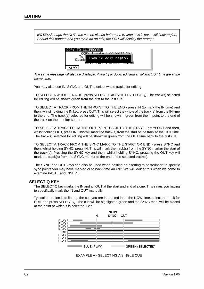
62 Version 1.00
EDITING
NOTE: Although the OUT time can be placed before the IN time, this is not a valid edit region.Should this happen and you try to do an edit, the LCD will display the prompt.
The same message will also be displayed if you try to do an edit and an IN and OUT time are at thesame time.
You may also use IN, SYNC and OUT to select whole tracks for editing.
TO SELECT A WHOLE TRACK - press SELECT TRK (SHIFT+SELECT Q). The track(s) selectedfor editing will be shown green from the first to the last cue.
TO SELECT A TRACK FROM THE IN POINT TO THE END - press IN (to mark the IN time) andthen, whilst holding the IN key, press OUT. This will select the whole of the track(s) from the IN timeto the end. The track(s) selected for editing will be shown in green from the in point to the end ofthe track on the monitor screen.
TO SELECT A TRACK FROM THE OUT POINT BACK TO THE START - press OUT and then,whilst holding OUT, press IN. This will mark the track(s) from the start of the track to the OUT time.The track(s) selected for editing will be shown in green from the OUT time back to the first cue.
TO SELECT A TRACK FROM THE SYNC MARK TO THE START OR END - press SYNC andthen, whilst holding SYNC, press IN. This will mark the track(s) from the SYNC marker the start ofthe track(s). Pressing the SYNC key and then, whilst holding SYNC, pressing the OUT key willmark the track(s) from the SYNC marker to the end of the selected track(s).
The SYNC and OUT keys can also be used when pasting or inserting to paste/insert to specificsync points you may have marked or to back-time an edit. We will look at this when we come toexamine PASTE and INSERT.
SELECT Q KEYThe SELECT Q key marks the IN and an OUT at the start and end of a cue. This saves you havingto specifically mark the IN and OUT manually.
Typical operation is to line up the cue you are interested in on the NOW time, select the track forEDIT and press SELECT Q. The cue will be highlighted green and the SYNC mark will be placedat the point at which it is selected. I.e.:
PLAYPLAYEDIT
PLAYPLAY
NOW
BLUE (PLAY) GREEN (SELECTED)
IN OUT
PLAYPLAY
PLAY
SYNC
EXAMPLE A - SELECTING A SINGLE CUE

Version 1.00 63
EDITING
This also works for stereo cues. Line the cues you are interested in on the NOW time, select bothrelevant tracks for EDIT and press SELECT Q. The IN and OUT will be placed at the start and endof the cues on both tracks and the SYNC marker placed at the point of selection. I.e.:
PLAYPLAYEDIT
PLAYPLAY
NOW
BLUE (PLAY) GREEN (SELECTED)
IN OUT
PLAYPLAY
SYNC
EDIT
EXAMPLE B - SELECTING A STEREO CUE ACROSS TWO TRACKS
You may also select multiple cues in this way. In this case, the IN and OUT will be placed at thestart and end of the longest cue(s) and anything that falls within that edit region will be selected.For example, imagine that you have this situation:
PLAYPLAYEDIT
PLAYPLAY
NOW
EDIT
EDITEDIT
BEFORE USING SELECT CUE
Pressing SELECT Q will give this result:
PLAYPLAYEDIT
PLAYPLAY
BLUE (PLAY) GREEN (SELECTED)
IN OUT
EDIT
EDITEDIT
NOWSYNC
EXAMPLE C - SELECTING MULTIPLE CUES
When multiple cues are selected (i.e. several tracks in edit), all selected cues are highlightedgreen. If you turn any of the selected tracks off, those cues are de-selected but, if you turn themback on again, they are re-selected. To select other cues on other tracks, simply turn them on forEDIT.
Cues selected using SELECT Q may be subjected to all the various editing functions available butwithout the need to specifically mark IN and OUT times.
It must be said that multiple cue selection is not the prime use of SELECT Q. Its principle use is toselect a single cue on one track (or stereo cue on two tracks) for editing (copying, cutting, erasing,slipping, nudging, timestretching or for setting the level and fade up/down parameters). However,you can, if you wish, use SELECT Q for selecting multiple cues in a larger edit region (for example,for setting the levels or a common fade down time for a group of cues). Although this can beachieved by specifically setting the IN and OUT times manually, you may find it saves you time touse SELECT Q.

64 Version 1.00
MULTI-MACHINE EDITING
MULTI- MACHINE EDITMulti-machine edit mode provides a quick and convenient method for copying audio from oneregion to another on the same track(s). For example, it can be used to copy the chorus of a songfrom one position to another. The only restriction in this mode is that audio cannot be moved fromone track to another. For edits that involve moving audio from one track to another, SINGLE-MACHINE EDIT should be used as described in a later section.
MULTI-MACHINE EDIT is selected by pressing the EDIT key and then selecting MULTI in theTRACKS field. You will see the following display similar to this:
The soft keys show the edit functions that are available.
COPYING A REGIONThis allows you to copy a selected audio region on any combination of tracks in the system to anew location on the GRID.
First, mark the region you want to copy using the IN and OUT keys and select the tracks containingaudio you wish to copy using the EDIT TRACK SELECT keys. Cues within the marked region willbe shown in green on the display to show that they are selected.
Next, press the COPY (F1) key. The audio region selected will ‘pop-out’ of the GRID and will beshown as a ‘ghost’ image in red on top of the original cues:
NOW
Audio region selected
Now, you can use any of the transport controls to move selected region to the position you want tocopy it to. You can use PLAY, REW, FF etc., as well as LOCATE functions and then the JOG wheelto ‘fine tune’ your selection. As you move to new areas in the GRID, the selected region will remainas a ‘ghost’ image referenced to the NOW time:
NOW
Jog wheel turned to the right to move the selected region

Version 1.00 65
MULTI-MACHINE EDITING
At the time you press COPY (F1) to select the audio region, you will also notice that the LCDchanges to show the following options:
The parameters on this page show:
LENGTH This is the length of the audio region selected
EDIT REFERENCE This selects how the audio region selected is referenced to the currentNOW time. The options are:
SOURCE SYNC- Referenced to the NOW time at which the audio regionwas selected:
NOW
SOURCE OUT- Reference to the end of the selected audio region:
NOW
SOURCE IN- Referenced to the start of the selected audio region:
NOW
The soft keys may be used to choose how the selected audio region will be copied back into theGRID at its new position.

66 Version 1.00
MULTI-MACHINE EDITING
MULTITRACK PASTEPressing PASTE (F1) will paste the selected region over any material at the current NOW time.You will note that any gaps in the material being pasted will be pasted over any material that existsat the paste point. For example:
MULTITRACK INSERTPressing INSERT (F2) will insert the selected region at the current NOW time and will cause anyaudio after the insert point to be shifted.
BEFORE INSERT
AFTER INSERT
NOW
SELECTED REGION
NOW
SELECTED REGION
TRACK BEFORE PASTE
TRACK AFTER PASTE
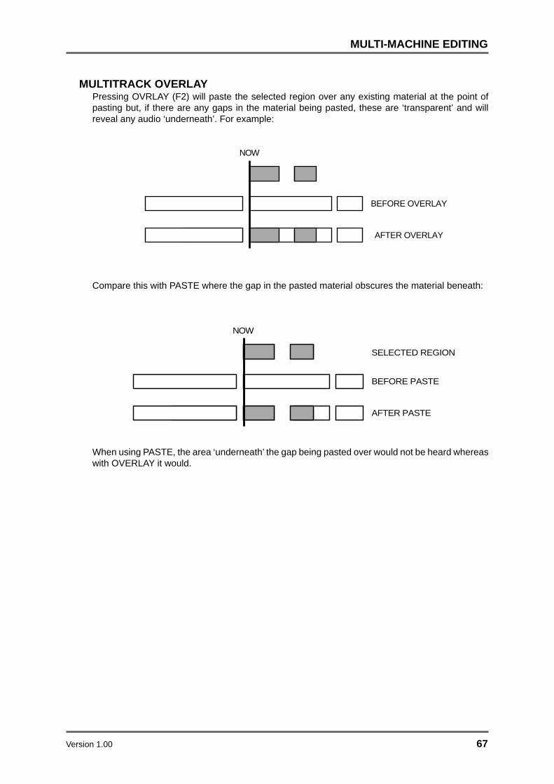
Version 1.00 67
MULTI-MACHINE EDITING
MULTITRACK OVERLAYPressing OVRLAY (F2) will paste the selected region over any existing material at the point ofpasting but, if there are any gaps in the material being pasted, these are ‘transparent’ and willreveal any audio ‘underneath’. For example:
NOW
BEFORE OVERLAY
AFTER OVERLAY
Compare this with PASTE where the gap in the pasted material obscures the material beneath:
NOW
BEFORE PASTE
AFTER PASTE
SELECTED REGION
When using PASTE, the area ‘underneath’ the gap being pasted over would not be heard whereaswith OVERLAY it would.

68 Version 1.00
MULTI-MACHINE EDITING
CUTThis allows you to remove a selected region of audio copy on any combination of tracks from theGRID and close the gap(s) thus created, shifting all audio after the edit accordingly. For example:
IN OUT
BEFORE CUT
AFTER CUT
First, mark the region you want to cut using the IN and OUT keys and select the tracks containingaudio you wish to remove using the EDIT TRACK SELECT keys. Cues within the marked regionwill be shown in green on the display to show that they are selected.
Next, press the CUT (F2) key on the main MULTI-MACHINE EDIT page. The audio region selectedwill be removed from the GRID and subsequent audio shifted accordingly.
ERASEERASE is similar to CUT except that it will remove the currently selected region but will keep anygap(s) thus created.:
IN OUT
IN OUT
BEFORE ERASE
AFTER ERASE
First, mark the region you want to cut using the IN and OUT keys and select the tracks containingaudio you wish to remove using the EDIT TRACK SELECT keys. Cues within the marked regionwill be shown in green on the display to show that they are selected.
Next, press the ERASE (F3) key on the main MULTI-MACHINE EDIT page. The audio regionselected will be removed from the GRID.
DISCARDThe DISCARD function will discard material on either side of the selected region but will not slipany subsequent audio:
IN OUT
IN OUT
BEFORE DISCARD
AFTER DISCARD
First, mark the region you want to cut using the IN and OUT keys and select the tracks containingaudio you wish to remove using the EDIT TRACK SELECT keys. Cues within the marked regionwill be shown in green on the display to show that they are selected.
Next, press the DISCARD (F4) key on the main MULTI-MACHINE EDIT page. Audio material oneither side of the selected region will be removed from the GRID.
The main use for DISCARD is to get rid of any rubbish from cues before a certain point and aftera certain point.

Version 1.00 69
MULTI-MACHINE EDITING
SPLIT EDITAs its name suggests, SPLIT allows CUES to be split in two. Each cue may then be edited separately.I.e.
BEFORE SPLIT
AFTER SPLIT
CUE 1
CUE 1 CUE 2
SPLIT
The process can be repeated almost indefinitely within one cue, splitting it up into smaller sectionseach time. EXECUTE is not required for SPLIT CUE.
The SPLIT function is executed by pressing SPLIT (F5) on the main MULTITRACK EDIT page:
As with other MULTITRACK EDIT functions, SPLIT may be used on any combination of tracks inthe system and can be useful to chop up individual sentences and phrases in a dialogue recordingor to split a music project into smaller sections.

70 Version 1.00
SINGLE-MACHINE EDITING
SINGLE MACHINE EDITMulti-machine edit mode provides a quick and convenient method for copying audio from oneregion to another on the same track(s). However, it is restricted in that audio cannot be movedfrom one track to another. This is to prevent you trying to copy audio from a track on one machineto a track on a different machine. For edits that involve moving audio from one track to anothertrack on the same machine, SINGLE-MACHINE EDIT can be used. This uses the EDIT CLIPBOARDas a temporary storage place for the audio regions being edited.
SINGLE-MACHINE EDIT is selected by pressing the EDIT key and then selecting the range oftracks you wish to edit in the TRACKS field. The ranges shown in the TRACKS field correspond tothe tracks assigned to each machine in the system (1-16, 17-32 etc..). When a TRACKS selectionfor a single machine has been made, you will see the following display:
The soft keys show the edit functions that are available, with MORE (F6) being used to scroll tomore functions. Before looking at the edit functions in details, we will first look at the EDITCLIPBOARD which is displayed while in SINGLE-MACHINE EDIT.
EDIT CLIPBOARDThe EDIT CLIPBOARD can be regarded as a temporary storage place for audio cues. It can holdup to ten clips, 0-9, which are available for pasting and inserting into a project at any time. WhenSINGLE-MACHINE EDIT is selected, the clipboard is automatically displayed at the right handside of the VGA monitor in the associated MACHINE BOX and here you can see the edits youhave placed in it.
1 Project 1Project 1
CLIPBOARD
O: Sax stab
1: Gtr hook
2: Strings1
3:
4:
5:
6:
7:
8:
9:
STOP
When you copy, cut or erase an edit to the clipboard, the name of the cue is shown in the clipboardnumber you have used. You may, if you wish, give an edit a different name prior to placing it in theclipboard so that you can see at a glance what is in the clipboard. When an edit is re-named in thisway, the new name will be used when you subsequently come to paste or insert the edit later on.
In the case where the IN/OUT markers straddle several cues that have different names, the nameof the first cue selected will be shown in the clipboard. When that edit is subsequently pasted orinserted back into the project, the original name will be shown.
Version 1.00 71
SINGLE-MACHINE EDITING
The EDIT CLIPBOARD is a very convenient way of having edits readily available for immediateaccess at any time. In a way, if you consider the analogy of tape editing, the clipboard is the digitalequivalent of putting certain useful edits to one side and hanging them up for use later on.
CLIPBOARD 0 is the default clipboard and unless another clipboard number is specifically selected,this is the clipboard number you will copy, cut or erase to or paste or insert from.
Using the clipboard is designed to be very quick and easy. At its simplest level, to copy an edit to,say, clipboard 5, simply mark the region you are interested in, press COPY, 5, EXECUTE. To pastethat back in elsewhere, press PASTE, 5, EXECUTE. Prior to copying it to the clipboard you couldgive it a name and prior to pasting it in, you can audition it to check you have selected the correctone.
You will find the EDIT CLIPBOARD an invaluable aid when editing. We will now move on to look atthe edit functions available from the soft keys in SINGLE-MACHINE EDIT.

72 Version 1.00
SINGLE-MACHINE EDITING
COPY TO CLIPBOARDThis will copy the edit region within the IN/OUT marks or will copy the currently selected CUE(s) tothe clipboard. Pressing COPY (F1) from SINGLE-MACHINE EDIT will display this screen:
You can see the length of the edit region/cue(s) in the COPY LENGTH field. You cannot accessthis field and is shown for information purposes only.
When you press COPY, the EXECUTE key’s LED will flash. Simply pressing the EXECUTE key atthis point will copy the edit region/cue(s) to the default edit clipboard 0 and will also close thisscreen. If you wish, however, you may like to copy the current edit region/cue(s) to one of thenumbered edit clipboards 1-9. To do this, press one of the number keys 1-9 on the numeric keypadbefore pressing EXECUTE. The clipboard number will be shown on the LCD. Pressing EXECUTEwill copy the edit region/cue(s) to the selected clipboard. For example, to copy the edit to clipboard5, press COPY, 5, EXECUTE.
If you wish, prior to copying the edit to a clipboard, you may give it a name for easier referencelater on. If you do not name it, it will take the name of the currently selected cue or the cue withinthe edit region. If multiple cues are selected, the name of the first cue will be shown in the selectedclipboard. However, when you come to paste this back in, the other cues in the region will retaintheir original names.
If you have a PS/2 keyboard attached to the RE32, you can name the edit prior to copying it. Asyou type the name on the keyboard, the CLIPBOARD NAME field will ‘open’:
You may enter a name of up to ten characters. Press RETURN to complete the naming processand RETURN again to complete the edit.
NOTE: if you rename a cue when copying it will use this name when subsequently pastedback in. If you name a region that has multiple cues in it, ALL the cues will share the samename when you come to paste it back in.
You may also select the type of edit you wish to copy using F1 - TYPE? (or by moving the cursorspecifically to the EDIT TYPE field). There are two choices you can make. WHOLE REGIONselects that everything within the IN/OUT region to be copied:
PLAYPLAYEDIT
PLAYPLAY
BLUE (PLAY) GREEN (SELECTED)
IN OUT
EDIT
EDITEDIT

Version 1.00 73
SINGLE-MACHINE EDITING
Selecting ONLY WHOLE CUES will copy only the whole cues whose’ start and end fall within theedit region:
PLAYPLAYEDIT
PLAYPLAY
BLUE (PLAY) OCHRE (SELECTED)
IN OUT
EDIT
EDITEDIT
Cues whose start and end fall outside the edit region will not be copied. When ONLY WHOLECUES is selected, the selected cues will be highlighted ochre on the external monitor.
NOTE: The selection made in this field is retained when you leave the page. When yousubsequently re-enter the COPY page, the selection you made previously will be shown.

74 Version 1.00
SINGLE-MACHINE EDITING
CUT TO CLIPBOARDCUT is similar to COPY except that, as well as copying the edit region/cue(s) to a clipboard, it alsoremoves the audio from the GRID and closes the gap thus created, shifting all audio after the editaccordingly. For example:
IN OUT
BEFORE CUT
AFTER CUT
Pressing CUT (F2) from SINGLE-MACHINE EDIT will display this screen:
The length of the edit region/cue(s) is shown in the CUT LENGTH field. The EXECUTE key’s LEDwill flash and if you press EXECUTE at this point, the selected edit region/cue(s) will be cut into thedefault clipboard 0. As with COPY, you may also cut an edit into the edit clipboard 1-9 using thenumeric keypad simply by pressing a number key as appropriate before pressing EXECUTE. Youmay also name the edit prior to cutting it to the clipboard by typing a suitable ten character nameon a PS/2 keyboard connected to the RE32. Press RETURN to complete the naming process andRETURN again to complete the CUT.
NOTE: As the process is identical, please refer to COPY TO CLIPBOARD for a detaileddescription of naming a clipboard.
F1 - - allows you to decide how subsequent audio will slip. Pressing this key will togglebetween SLIP WHOLE TRACK and SLIP ONLY CUE in the SLIP TYPE field. The effect is:
IN OUT
BEFORE CUT
AFTER CUT - SLIP WHOLE TRACK
AFTER CUT - SLIP ONLY CUE
With SLIP whole track, everything after the CUT slips to accommodate the edit whereas with SLIPONLY CUE selected, only the current cue is slipped. In this way, you can create cuts withoutaffecting subsequent cues which will remain unaffected.
NOTE: The selection made here is retained when you leave the page. When you subsequentlyre-enter the CUT page, the selection you made previously will be shown.

Version 1.00 75
SINGLE-MACHINE EDITING
CUT FORWARDS TO CLIPBOARD (SHIFT+CUT)Pressing SHIFT + CUT (F2) from SINGLE-MACHINE EDIT allows the opposite of CUT in that itremoves the selected edit region or cue(s) but slips all audio before the edit in time accordingly:
IN OUT
BEFORE -> CUT
AFTER -> CUT
This type of cut may be used when you need to get rid of something but all audio after the cut pointis perfectly synced. As with CUT, you may cut the edit region/cue(s) to a clipboard. PressingSHIFT + CUT (F2) from SINGLE-MACHINE EDIT will display this screen:
The length you are about to cut is shown in the CUT LENGTH field. You may cut the edit region/cue(s) and place it in the default edit clipboard 0 simply by pressing EXECUTE at this point. Youmay wish to cut it and place it in one of the clipboards 1-9.
You may also name the edit prior to cutting it to the clipboard by typing a suitable ten charactername on a PS/2 keyboard connected to the RE32. Press RETURN to complete the naming processand RETURN again to complete the CUT.
NOTE: As the process is identical, please refer to COPY TO CLIPBOARD for a detaileddescription of naming a clipboard.
The key (F1) allows you to decide how material before the cut will be affected. With SLIPWHOLE TRACK selected, all material prior to the cut will skip to accommodate the edit. With SLIPONLY CUE selected, only the cue you are working on will be affected. For example:
IN OUT
BEFORE -> CUT
AFTER -> CUT - SLIP WHOLE TRACK
AFTER -> CUT - SLIP ONLY CUE
NOTE: The selection made here is retained when you leave the page. When you subsequentlyre-enter the >CUT page, the same selection as you made previously will be shown.

76 Version 1.00
SINGLE-MACHINE EDITING
ERASE TO CLIPBOARDERASE is similar to CUT except that it will remove the currently selected edit region/cue(s) but willkeep the gap thus created.
IN OUT
IN OUT
BEFORE ERASE
AFTER ERASE
Pressing ERASE (F3) from SINGLE-MACHINE EDIT will give you this screen:
As with the other screens we have seen so far, the length you are about to erase is shown. Whenyou press EXECUTE now, the selected edit region/cue(s) will be erased and placed in defaultclipboard 0 and given the default name Clip 0. If you wish, you may erase the edit region/cue(s)and place it in one of the clipboards 1-9. You may also name it prior to erasing it by entering asuitable ten character name from a PS/2 keyboard connected to the RE32.
You may also select the type of edit you wish to erase using F1 - TYPE?. There are two choicesyou can make. WHOLE REGION selects that everything within the IN/OUT region will be erased:
PLAYPLAYEDIT
PLAYPLAY
BLUE (PLAY) GREEN (SELECTED)
IN OUT
EDIT
EDITEDIT
Selecting ONLY WHOLE CUES will erase only the whole cues whose’ start and end fall within theedit region:
PLAYPLAYEDIT
PLAYPLAY
BLUE (PLAY) OCHRE (SELECTED)
IN OUT
EDIT
EDITEDIT
Cues whose start and end fall outside the edit region will not be erased. When ONLY WHOLECUES is selected, the selected cues will be highlighted ochre on the external monitor.
NOTE: The selection made here is retained when you leave the page. When you subsequentlyre-enter the ERASE page, the same selection as you made previously will be shown.

Version 1.00 77
SINGLE-MACHINE EDITING
DISCARDThe DISCARD function will discard material either side of the IN/OUT area but will not slip anysubsequent audio.
IN OUT
IN OUT
BEFORE DISCARD
AFTER DISCARD
The DISCARD function is accessed from the second group of edit functions shown when theMORE (F6) key is pressed on the main edit page. Pressing MORE (F6) followed by DISCARD(F2) from SINGLE-MACHINE EDIT will give you this screen:
Pressing EXECUTE will complete the action.
The main use for DISCARD is to get rid of any rubbish in a cue before a certain point and after acertain point. For example, you may have a sound effect of a door slam which you recordedespecially and, either side of the effect is talking, background noise and other such noises. To getrid of this, mark the start and end of the door slam and press DISCARD (SHIFT+ERASE) - this willkeep the slam and remove the unwanted material either side of the IN/OUT marks.
Because this function’s primary use is purely to clear out unwanted ‘handles’, you cannot discardthe material either side of the IN/OUT marks to a clipboard or a library. If, for some reason, youreally want to keep this material for later, you should mark these regions specifically and useERASE and place them in a clipboard or library.
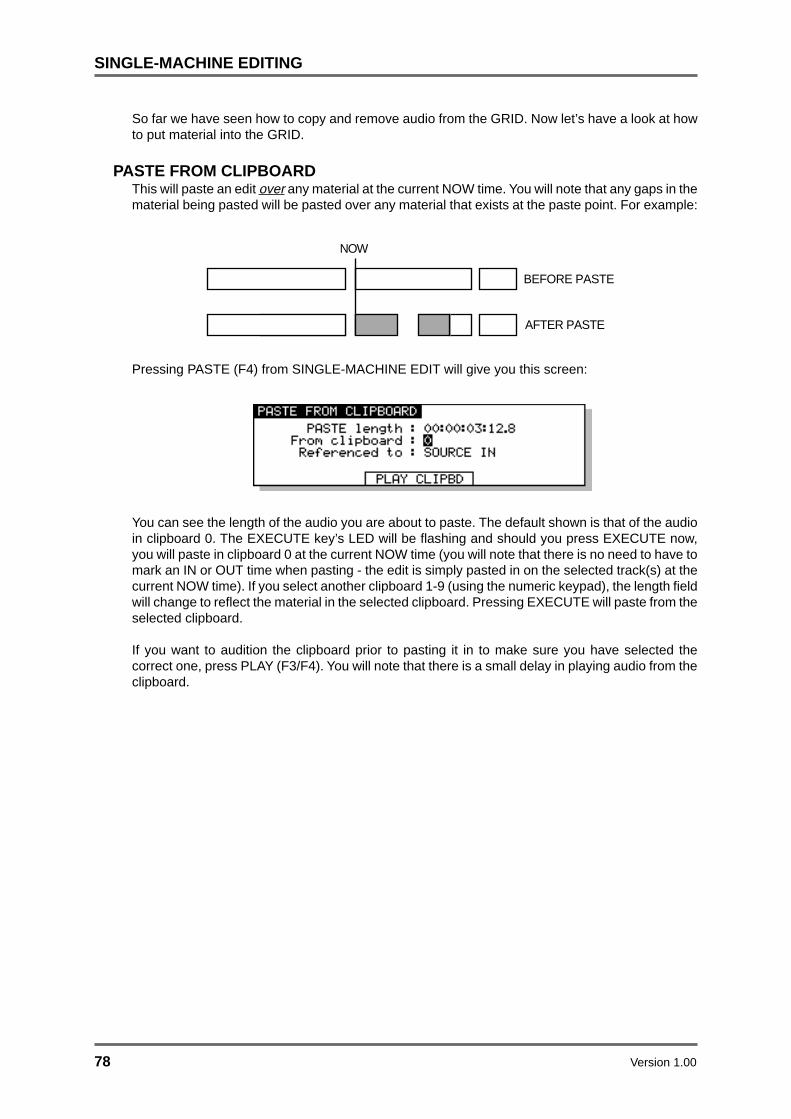
78 Version 1.00
SINGLE-MACHINE EDITING
So far we have seen how to copy and remove audio from the GRID. Now let’s have a look at howto put material into the GRID.
PASTE FROM CLIPBOARDThis will paste an edit over any material at the current NOW time. You will note that any gaps in thematerial being pasted will be pasted over any material that exists at the paste point. For example:
NOW
BEFORE PASTE
AFTER PASTE
Pressing PASTE (F4) from SINGLE-MACHINE EDIT will give you this screen:
You can see the length of the audio you are about to paste. The default shown is that of the audioin clipboard 0. The EXECUTE key’s LED will be flashing and should you press EXECUTE now,you will paste in clipboard 0 at the current NOW time (you will note that there is no need to have tomark an IN or OUT time when pasting - the edit is simply pasted in on the selected track(s) at thecurrent NOW time). If you select another clipboard 1-9 (using the numeric keypad), the length fieldwill change to reflect the material in the selected clipboard. Pressing EXECUTE will paste from theselected clipboard.
If you want to audition the clipboard prior to pasting it in to make sure you have selected thecorrect one, press PLAY (F3/F4). You will note that there is a small delay in playing audio from theclipboard.

Version 1.00 79
SINGLE-MACHINE EDITING
PASTING TO OUT AND SYNC REFERENCESIt is also possible to paste material in a variety of different ways. The default is to paste the IN pointof the source material at the current NOW time. For example:
NOW
BEFORE PASTE
AFTER PASTE
However, you may paste in material referenced to the source material’s OUT point simply bypressing the OUT key prior to pasting. This will place the source material’s OUT point on the NOWtime pasting over preceding material. For example:
NOW
BEFORE PASTE
AFTER PASTE + OUT
Known as ‘back-timing’, this is useful where you want a cue to end at a specific point but its startpoint is not so important. For example, you may want a piece of music to end at a certain point(maybe at the end of a scene). Locate to the end of the scene and jog over the exact point youwant and then press PASTE, OUT, EXECUTE (to paste from default clipboard 0) or PASTE, OUT,1-9, EXECUTE (to paste from the edit clipboard)1 . As you press the OUT key, so you will see theLCD’s ‘REFERENCED TO’ field change to SOURCE OUT. If you wish, you may specifically movethe cursor to this field and change it using the DATA ENTRY +/- keys.
It is also possible to paste material referenced to the source material’s SYNC point. Assuming youmarked a SYNC point in the source material, press PASTE, SYNC, EXECUTE. The following willoccur:
NOW
BEFORE PASTE
AFTER PASTE + SYNC
You may also paste and sync an edit from the clipboard - i.e. PASTE, SYNC, 8, EXECUTE topaste the sync point of clipboard 8 to the current NOW time .
This is similar to back-timing except that you can set the exact position you want synced, not justthe end. You may use this, for example, to sync up a music crescendo with a dramatic point in thevisuals or you may use this to back time the end of some music or dialogue or a sound effect(some passing traffic, perhaps) so that the very end of the cue maybe trails over into the nextscene. Whatever. There are many uses for this which you will no doubt discover for yourself.
NOTE: If you try to paste referenced to a SYNC mark and there isn’t one, it will paste referencedto the source material’s IN point
1 In fact, the actual order in which you press the keys is not that important. For example, you maypress PASTE, 8, OUT, EXECUTE to paste the out time of clipboard 8 the current NOW time or youmay press PASTE, OUT, 8, EXECUTE to achieve the same effect. Similarly, the order you pressthe clipboard and SYNC keys is not important.

80 Version 1.00
SINGLE-MACHINE EDITING
INSERT FROM CLIPBOARDThis will insert an edit at the current NOW time and will cause any audio after the insert point to beshifted.
BEFORE INSERT
AFTER INSERT
NOW
Pressing INSERT (F5) from SINGLE-MACHINE EDIT will give you this screen:
The default selection is to insert material from clipboard 0 but you may, of course, insert materialfrom any of the clipboards 1-9 by selecting the appropriate number on the numeric keypad. Thelength of the insert will be shown in the INSERT LENGTH field. Press EXECUTE to complete theinsert.
Prior to inserting the item from the clipboard, if you at all unsure what it is you are inserting, usePLAY CLIPBD to audition it.
You can use the key to select whether the whole track will slip to accommodate the insert(SLIP WHOLE TRACK) or just the remainder of the cue at the point of insert (ONLY SLIP CUE) willslip. The result would be:
BEFORE INSERT
AFTER INSERT
NOW
AFTER INSERT - SLIP ONLY CUE
NOTE: The selection made here is retained when you leave the page. When you subsequentlyre-enter the INSERT page, the same selection as you made previously will be shown.

Version 1.00 81
SINGLE-MACHINE EDITING
INSERTING TO OUT AND SYNC REFERENCESAs with PASTE and OVERLAY, you may also insert material referenced to the source material’sOUT point by pressing INSERT, OUT, EXECUTE. The REFERENCED TO field in the LCD willshow OUT and the effect would be as follows:
BEFORE INSERT
AFTER INSERT + OUT
NOW
In this example, the inserted material all audio before the NOW time would slip allowing you toback-time the insert.
You may also insert referenced to the source material’s SYNC mark. This is useful for bringing inmaterial that needs to synchronise to specific visual events or to another piece of audio (a clichédexample would be to sync a music crescendo to a gun shot).
Pressing INSERT, SYNC, EXECUTE would give this result:
BEFORE INSERT
AFTER INSERT + SYNC
NOW
NOTE: If you try to insert referenced to a SYNC mark and there isn’t one, it will insert referencedto the source material’s IN point
In both examples, you may also use the clipboards 1-9. For example, INSERT, OUT, 6, EXECUTEwould insert clipboard 6 referenced to its OUT point.

82 Version 1.00
SINGLE-MACHINE EDITING
OVERLAY FROM CLIPBOARDOverlay is similar to PASTE in that it pastes over any existing material at the point of pasting but,if there are any gaps in the material being pasted, these are ‘transparent’ and will reveal any audio‘underneath’. For example:
NOW
BEFORE OVERLAY
AFTER OVERLAY
Compare this with PASTE where the gap in the pasted material ‘obscures’ the material beneath it.
NOW
BEFORE PASTE
AFTER PASTE
When using PASTE, the area ‘underneath’ the gap being pasted over would not be heard whereaswith OVERLAY it would.
The OVERLAY function is accessed from the second group of edit functions shown when theMORE (F6) key is pressed on the main edit page. Pressing MORE (F6) followed by OVERLAY(F4) will display this screen:
As with paste, you may overlay material from the default clipboard 0 or from clipboards 1-9.EXECUTE completes the action and closes the screen. If you are not sure of the clipboard youhave selected to OVERLAY, you can press PLAY to audition it prior to committing it.
OVERLAYING TO OUT AND SYNC REFERENCESYou may overlay referenced to the source material’s SYNC or OUT points simply by pressingSYNC or OUT prior to pressing EXECUTE (see PASTING TO SYNC OR OUT REFERENCES fora detailed description of using the SYNC and OUT keys for back-timing as the function is essentiallyidentical even if the end result is slightly different).

Version 1.00 83
SINGLE-MACHINE EDITING
MOVE REGIONThe MOVE function allows you to move a cue or an edit region to another track. This is faster andmore convenient than using ERASE to remove the cue/region from one selected track, de-selectingthat track and selecting the destination track and then pasting it back in.
The MOVE function is accessed from the second group of edit functions shown when the MORE(F6) key is pressed on the main SINGLE-MACHINE EDIT page. To move a cue/region from onetrack to another, select the source track using the TRACK EDIT keys and then select the cue ormark the region you want to move. Press MORE (F6) followed by MOVE (F1). You will see thisscreen:
Select the ‘destination’ track in the TO TRACK field and press EXECUTE to move the region. Thecue/region on the track selected for editing will be moved from the ‘source’ track and will be placedat exactly the same time on the track specified in this field.
In the case of moving several tracks, the TO TRACK field sets the first track the lowest numberedtrack will move to - all other tracks selected for edit will be moved to adjacent tracks. For example,select tracks 6, 7, 8 for EDIT, press 1 of the numeric keypad to select 1 - tracks 6, 7, 8 will bemoved to tracks 1, 2, 3.
IMPORTANT NOTE: Existing cues or overlapping cues on the destination tracks will be pastedover.
This function is only intended as a simple way to move audio from one track to another at the sametime location. For more complex moves, you should use CUT/ERASE and PASTE/INSERT.
Pressing the BY AMOUNT soft key will take you to the MOVE REGION BY AMOUNT page whichallows you to move a cue or region by a specified amount.
First select the source track using the TRACK EDIT keys and then select the cue or mark theregion you want to move. Select the amount you wish to move the audio by in the MOVE DISTANCEfield and press EXECUTE to move the region. The cue/region on the track selected for editing willbe moved by the specified amount.

84 Version 1.00
SINGLE-MACHINE EDITING
NUDGING IN/SYNC/OUT TIMESThis allows you to use the DATA ENTRY +/- keys to slip and nudge edits or audio into position. TheNUDGE function is accessed from the second group of edit functions shown when the MORE (F6)key is pressed on the main SINGLE MACHINE EDIT page. Pressing MORE (F6) followed byNUDGE (F3) will display this screen:
This is a graphic representation of what is happening when you nudge. This page allows you tonudge the NOW time into position prior to marking an IN, SYNC or OUT time. For example, if youcannot set an edit precisely using the JOG wheel, you can use this page to nudge the NOW timeinto position using the DATA ENTRY +/- keys which will nudge the NOW time, frame by frame, untilit is at exactly the right position. Typically, you would use this by roughly jogging over an edit pointusing the JOG wheel, pressing NUDGE and use the + or - keys to nudge backwards or forwards inincrements of frames, maybe use PLAY TO and/or FROM to audition the point and then mark anIN, SYNC or OUT point as appropriate.
You can also hold down the SHIFT key while pressing the DATA ENTRY +/- keys to nudge inincrements of sub-frames (however, please see below - NUDGE SET - as you can set the incrementsby which the NOW time will be nudged).
You may also use NUDGE with SELECT Q to set the SYNC point at which you mark the cue. Lineup the cue you are interested in on the NOW time and press NUDGE. Now use the +/- keys tonudge the NOW time and, when you’re happy with the position, press SELECT Q. The cue will beselected and the SYNC point will be marked on the NOW time you have just set.
NUDGING AUDIOIt is also possible to physically nudge and slip audio into position using the NUDGE function.Pressing F5/F6 gives this screen:
To nudge audio (that is, to physically slip it in time), you must first select and IN and OUT region.This may be done before or after entering NUDGE AUDIO. Assuming the appropriate tracks areselected for EDIT, this can be done in a number of ways...
To select a single cue for nudging, line the cue you wish to nudge onto the NOW time and pressSELECT Q. The cue will be highlighted green on the external monitor. For stereo cues, select thetracks for edit as necessary.
To select a specific IN and OUT region to nudge, mark the IN and OUT points where necessary.The edit region will be highlighted green on the selected track. You may also select several tracks.
To select everything from the NOW time to the end of the track to nudge, press and hold the IN keyand press OUT. Everything from the NOW time to the end of the track will be selected and highlightedgreen on the external monitor. You may do this across several tracks.
To select everything from the NOW time to the start of the track to nudge, press and hold theOUT key and press the IN key. Everything from the NOW time back to the start of the track willbe selected and highlighted green on the external monitor. You may do this across severaltracks.

Version 1.00 85
SINGLE-MACHINE EDITING
To select the whole track to nudge, press and hold SYNC then press IN and OUT together. Thiswill mark the whole of the selected track and it will be highlighted green on the external monitor.You may, of course, have multiple tracks selected for editing.
However you mark it, as soon as you press the DATA ENTRY + or - keys, the selected audio willslip forwards or backwards in increments of one frame or press +/- keys while holding the SHIFTkey down to slip in smaller increments of sub-frames (however, please see below - NUDGE SET- as you can set the increments by which the audio will be nudged). If you are in the middle of acue, as soon as you nudge it, the cue will be split and the audio slipped.
UNDOING A NUDGEYou cannot undo a nudge directly within the NUDGE pages but, when you leave the page, if youfeel the result was unsuccessful, you may undo it. When in the NUDGE page, if you feel an edit isnot working well, leave NUDGE temporarily, hit UNDO and re-enter NUDGE to have anotherattempt.
NUDGE SET (SHIFT+NUDGE)The NUDGE key’s shift function, SET, allows you to set by how much the +/- keys will nudge.Pressing SHIFT+NUDGE (F3) will display this screen:
The fields on this page are:
DATA +/- KEYS Here you may set the amount the DATA +/- keys will nudge. The usualselection (and hence the default) is 1 frame. You may select from 1-25frames (or 24 or 30 depending on the frame rate of the timecode typeyou are using).
SHIFT+DATA +/- KEYS This field allows you to set the amount by which the DATA +/- keys willnudge when the SHIFT key is held at the same time. The default is 1sub-frame and you may select from 1-9 sub-frames.
Pressing EXIT will leave this screen at any time.

86 Version 1.00
SINGLE-MACHINE EDITING
SPLIT CUEAs its name suggests, SPLIT will split a cue in two. Although this can be done in other ways(NUDGE, IN->NOW, CUT, ERASE, etc.), these all involve either removing audio or moving it.SPLIT just splits the cue in two, making two cues out of one. Each cue may then be edited separately.I.e.:
BEFORE SPLIT
AFTER SPLIT
CUE 1
CUE 1 CUE 2
SPLIT
The process can be repeated almost indefinitely within one cue, splitting it up into smaller sectionseach time. EXECUTE is not required for SPLIT CUE.
The SPLIT function is accessed from the second group of edit functions shown when the MORE(F6) key is pressed on the main edit page. Pressing MORE (F6) followed by SPLIT (F5) fromSINGLE-MACHINE EDIT will execute a SPLIT.
You may find this function useful in many ways. You may like to chop up individual sentences andphrases in a dialogue recording or split a music cue into smaller sections.
You may use it to create a cue within a longer cue. For example, you may wish to ‘duck’ a sectionof a long music cue so as not to overpower a bit of dialogue or a specific sound effect. Firstly, go tothe start of the section in CUE 1 you wish to ‘duck’ and press SPLIT. This will create CUE 2. Nowfind the end of the section you wish to ‘duck’ and press SPLIT again - this will create CUE 3. Youwill end up with this:
BEFORE SPLIT
AFTER SPLIT
CUE 1
CUE 1 CUE 2
SPLIT
CUE 3
Now jog back into CUE 2 (or hold down GOTO and press the DATA ENTRY ‘-’ key to go to theprevious cue) and press SELECT Q, followed by EDIT Q - you may now edit CUE 2’s level parameter,bringing it down by a few dB’s.
(See EDIT CUE section for details about setting cue levels)

Version 1.00 87
SINGLE-MACHINE EDITING
Three other edit related features are available as SHIFT functions on the IN, SYNC and OUT keys.
IN->NOW (SHIFT+IN)The IN key’s shift function, IN->NOW, allows you to slip audio by moving the marked edit region/cue(s) time to the current NOW time.
For example, to move a piece of audio to a new position, mark an edit region as appropriate, play,jog, locate or whatever to the point you want it and press IN->NOW. The edit region’s IN point willbe repositioned at the current NOW time. I.e.:
IN/NOW
IN NOW
IN NOW
In this way, you may move a piece of audio into sync. Let’s take a practical example. Imagine youare working with the system connected to a VTR using RS422. You have pasted or inserted a fewdog bark sound effects but one of them is slightly early and out of sync with the picture. Firstly,mark an IN at the start of the out-of-sync dog bark and then mark an OUT at the end of it (or line upthe dog bark on the NOW time and press SELECT Q). For example:
Now, jog the video forward from the RE32’s jog wheel (ignore the audio for the moment) until yousee where the dog’s mouth is just beginning to open. Jog back and forth until you get an exactsync point and press IN->NOW (SHIFT+IN) followed by EXECUTE. The offending dog bark will bemoved forward and re-positioned at the exact point where the mouth opens. I.e.:
Of course, it may be that you need to slip the entire track in this way. To achieve this, press IN andthen, whilst holding the IN key, press OUT - this will select the whole of the track from the IN timeonwards and will slip it backwards or forwards accordingly.
If you wish to slip only a cue, use SELECT Q. This will mark the IN and OUT at the start and endof the selected cue and IN->NOW will slip the cue accordingly.
Pressing IN->NOW gives this screen:
You can see how much you have moved the IN time in the SLIP DISTANCE field. If you moveforwards (i.e. jog clockwise, fast forward, play), a ‘+’ appears before the SLIP DISTANCE field; ifyou move backwards (i.e. jog counter clockwise, rewind or play reverse), a ‘-’ sign appears. As youjog or play or rewind with this page open, you will see this time field changing. Press EXECUTE tocomplete the action.

88 Version 1.00
SINGLE-MACHINE EDITING
Of course, you may not always want to slip the IN time to the NOW position - you may wish tomove an edit region’s/cue’s SYNC marker or OUT point to the NOW time.
As the screen informs you, these are selected using the SYNC and OUT keys. Pressing SYNCdisplays this screen:
The effect of this would be as follows:
IN SYNC OUTNOW
IN SYNC OUT
The SYNC point is moved to the NOW time. Of course, if you were to have pressed SYNC andthen OUT together, you would have selected the whole track from the SYNC point to the end andthe whole track would be slipped accordingly. You could also press SYNC plus IN and OUT togetherto slip the whole track from start to finish referenced to the SYNC point. In the above example,however, we have marked a specific edit region to slip.
You may use SELECT Q to good effect in this case. Because the action of selecting a cue marksa SYNC mark at the point you press SELECT Q, line up the cue at the point you want to sync andpress SELECT Q. The cue will be selected and the SYNC will be marked. Now use SYNC TONOW followed by EXECUTE.
You may also need to slip the edit region’s/cue’s OUT time to the NOW time. Pressing OUT displaysthis screen:
The effect of this using the above example would be as follows:
IN SYNC OUTNOW
OUTIN SYNC
Here, the OUT point has slipped backwards to the NOW time when you press EXECUTE. However,this function could be used to slip a cue forwards, slipping the cue’s OUT point to the NOW time.By pressing OUT and holding it while you press IN, you may slip a track from its start to theselected OUT time backwards and forwards.

Version 1.00 89
SINGLE-MACHINE EDITING
To revert to slipping the IN time to the NOW time after selecting SYNC to NOW or OUT to NOW,press the IN key.
NOTE: The IN->NOW (and SYNC and OUT->NOW) can paste over material (as in the aboveexample of OUT->NOW). Please be careful not to accidentally lose data this way. If you makea mistake, you can use UNDO to repair it.
Of course, you can also use the NUDGE function to move and slip audio around but the IN->NOW offers a more tactile and ‘physical’ way of syncing audio to picture that nudging (whilstalso useful) does not always offer.

90 Version 1.00
SINGLE-MACHINE EDITING
EDIT PLAY KEYSThe special play keys above the main transport keys are normally used when editing to check thelocation of edit points. Typical operation is to jog over an edit point and use PLAY TO or PLAYFROM to audition them quickly.
PLAY TONOW
PLAY FROM
NOW
Playback response time of these keys is extremely fast allowing rapid auditioning. Once you arehappy that you are at the right point, you can mark an IN, SYNC or OUT time as appropriate. Ofcourse, you may mark the IN, SYNC or OUT and then use these edit play keys, maybe nudgingthe NOW time, auditioning and re-marking the point.
The default PLAY TO time is 1 second but, if you need longer times, you may change this bypressing SHIFT+PREROLL to go to the PREROLL SETUP page and then PLAY TIMES (F1/F2) togo to this screen:
Here, you may set the play duration for the PLAY TO and PLAY FROM keys. You may reset theplay durations at any time by pressing RESET (F5/F6).
Once an edit region has been marked or a cue has been selected, you may use the PLAY IN >OUT key to listen to the edit region:
IN OUTPLAY IN>OUT
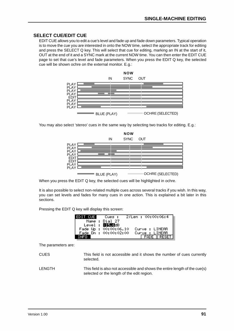
Version 1.00 91
SINGLE-MACHINE EDITING
SELECT CUE/EDIT CUEEDIT CUE allows you to edit a cue’s level and fade up and fade down parameters. Typical operationis to move the cue you are interested in onto the NOW time, select the appropriate track for editingand press the SELECT Q key. This will select that cue for editing, marking an IN at the start of it,OUT at the end of it and a SYNC mark at the current NOW time. You can then enter the EDIT CUEpage to set that cue’s level and fade parameters. When you press the EDIT Q key, the selectedcue will be shown ochre on the external monitor. E.g.:
PLAYPLAYEDIT
PLAYPLAY
NOW
BLUE (PLAY) GREEN (SELECTED)
IN OUT
PLAYPLAY
PLAY
SYNC
You may also select ‘stereo’ cues in the same way by selecting two tracks for editing. E.g.:
PLAYPLAYEDIT
PLAYPLAY
NOW
BLUE (PLAY) GREEN (SELECTED)
IN OUT
PLAYPLAY
EDIT
SYNC
When you press the EDIT Q key, the selected cues will be highlighted in ochre.
It is also possible to select non-related multiple cues across several tracks if you wish. In this way,you can set levels and fades for many cues in one action. This is explained a bit later in thissections.
Pressing the EDIT Q key will display this screen:
The parameters are:
CUES This field is not accessible and it shows the number of cues currentlyselected.
LENGTH This field is also not accessible and shows the entire length of the cue(s)selected or the length of the edit region.
OCHRE
OCHRE

92 Version 1.00
SINGLE-MACHINE EDITING
NAME This field shows the name of the currently selected cue(s). It also allowsyou to rename the cue(s). To do this, move the cursor to this field andenter a ten character name from a PS/2 keyboard connected to the RE32.Press RETURN to complete the name and RETURN again to rename it.
If only one track is selected for edit, you will, of course, only rename thatone cue. If more than one track is selected (for example, when editing astereo cue across two tracks), the name of the cue on the lowestnumbered track will be shown. Naming stereo or multiple cues will causeall the cues selected to share the same name.
LEVEL You may set the level of the cue(s) in this field. You may, input datanumerically from the keypad or using the DATA +/- keys if the leveladjustment you require is particularly fine (i.e. -3.5dB). To do this, movethe cursor the LEVEL field and type in a number as appropriate.
If several cues are selected, this parameter allows you to set the levelfor all cues. You will note, however, that, as with all EDIT CUE parameters,as soon as you edit the level here, ALL cues will be set to the samelevel. If you need to adjust levels of cues relative to each other, each cueshould be edited separately.
FADE UP Here you may set a fade up time for the cue. When a fade up time is set,it will be displayed on in the cue’s block display on the monitor screen (ifselected in the SHOW ON VGA pages). The fade up time can only be aslong as the cue itself or the length of the cue minus any fade down thatmay have been set.
If stereo or multiple cues are selected, you can set the fade up for all ofthem simultaneously.
CURVE This selects the fade up curve and you have a choice of three.
LINEAR ( ) - This selects a straight, linear fade curve.
LOG ( ) - This selects a logarithmic curve as shown.
SINE ( ) - This selects an equal power fade curve that ensures aneven level across crossfades.
FADE DN Here you may set a cue’s fade down time. When a fade down is set, it isshown graphically on the monitor screen (if selected in the SHOW ONVGA pages). The fade down time can only be as long as the cue itself orthe length of the cue minus a fade up time that may have been set.
CURVE As for FADE UP.

Version 1.00 93
SINGLE-MACHINE EDITING
Pressing INFO (F1) from the EDIT CUE screen gives the following information about the selectedcue(s):
Pressing FADE (F5) from the EDIT CUE screen gives you this screen:
START TO NOW (F3/4) executes a fade up from the beginning of the cue to the NOW time.
NOW TO END (F5/6) executes a fade down to the end of the cue, starting at the NOW time.
Pressing RESET (F6) from the EDIT CUE screen gives you the option of resetting the EDIT CUEparameters to zero - i.e. level to 0.0dB and fades to 00:00:00:00.0. This may be useful if youchange your mind about some settings you have made and wish to start again.
You may also UNDO your efforts in EDIT CUE. You cannot undo anything whilst actually in EDITCUE but, as soon as you leave EDIT CUE, you can restore the parameters to the state they werein when you entered it.

94 Version 1.00
SINGLE-MACHINE EDITING
USING EDIT CUE TO AFFECT MULTIPLE CUESYou can also set the level and fade parameters for groups of cues by marking an IN and OUT time(or using SELECT Q). This will select all cues within the IN/OUT region thus:
PLAYPLAYEDIT
PLAYPLAY
BLUE (PLAY) GREEN (SELECTED)
IN OUT
EDIT
EDITEDIT
NOWSYNC
Pressing EDIT Q will select only those cues whose’ start and end points fall within the edit regionwill be selected (highlighted ochre). Those cues whose’ start and end do not fall within the editregion will not be selected. For example, pressing EDIT Q in the above example would show this:
EDITEDIT
EDITEDIT
PLAYPLAY
PLAYPLAY
IN OUTSYNC
NOW
BLUE (PLAY) GREEN (SELECTED)
When several cues are selected for editing in this way, all cues take as their parameters those youhave set in the EDIT CUE page and all the cues selected will be set to the same value(s).
However, whilst this can be useful in some cases (for example, setting the fade down and levelparameters of a group of footstep sound effects so that they are all identical), it could potentiallycause problems in other cases because you may accidentally reset parameters you have previouslyset on some cues! The RESET function won’t help in this case as this will simply reset ALL cues’parameters to their default value of 00. Please be aware of this. In the event of a mistake, you canalways use UNDO, of course.
EDIT CUE is really designed to set level and fade for single or stereo cues and for re-naming cues.The multiple cue editing is included as a convenience for those times when you wish to setparameters to a group of the same or similar cues.
As mentioned, typical operation would be to line up the mono or stereo cue(s) you want to edit onto the NOW time, select the track(s) as appropriate, press SELECT Q and then EDIT Q and set thelevel, fade up and fade down parameters as necessary. Then press GOTO +/- to select the next orprevious cue, hit SELECT Q again and repeat the process if necessary.
OCHRE

Version 1.00 95
EDIT TOOLS
CROSSFADE TOOLSThe crossfade tools allow you to modify a cue’s start and end point to create a crossfaded overlapor to remove the gap between two cues and butt them together.
While in the CROSSFADE TOOLS page, the width of the tracks is halved on the display in order toclearly show overlaps of cues sharing the same track:
All the CROSSFADE TOOLS can be applied to a single track or across multiple tracks limited, inthe case of cross fades, by the amount of audio buffer RAM you have fitted in each machine.Where appropriate, therefore, the term ‘cue’ can also be read as ‘cues’.
The standard transport controls are disabled while in the CROSSFADE TOOLS pages.
Pressing the XFADE key (SHIFT+EDIT Q) takes you to main CROSSFADE TOOLS page whereyou have access to each of the ‘Quick Tool’ options - XFADE, BUTT, FADES - as shown below:

96 Version 1.00
EDIT TOOLS
Pressing XFADE (F1) on the CROSSFADE TOOLS page takes you to this screen:
The parameters are:
AMOUNT The amount by which the two cues are to overlap.
METHOD The method by which the overlap is to be achieved (TRIM or SLIP) andmay be selected either using the DATA ENTRY +/- keys or more directlyusing F1 and F2.
When TRIM is selected, one or both of the cues will be extended; thisassumes that the cue in question has a handle available for extension.Note that the targeted cue turns yellow, while the passive cue staysgreen.
With SLIP selected, either the PRE or the POST cue (not BOTH) isactually moved along the timeline. SLIP IN can also be selected fromwithin the TRIM page by pressing the IN key while pressing SHIFT.Similarly, OUT + SHIFT selects SLIP OUT.
SLIP mode is clearly dangerous if working to picture, hence the cues inquestion turn red in warning. Note that, when SLIP is selected F3becomes active as SLIP? and toggles between slipping just the cue orthe entire track:
ADJUST Selects which point(s) is to be adjusted:
PRE (F4) Selects the PRE point for adjustment.
POST (F5) Selects the POST point for adjustment.
BOTH (F6) Selects both PRE and POST points for adjustment.
Having set the required parameters, press the EXECUTE key to proceed.

Version 1.00 97
EDIT TOOLS
Pressing BUTT (F2) on the main CROSSFADE TOOLS page gives you this screen:
METHOD Selects the method by which the BUTT is to be achieved .
With TRIM selected, one or both of the cues will be extended; thisassumes that the cue in question has a handle available for extension.Note that the targeted cue turns yellow, while the passive cue staysgreen.
SLIP (F2) selects SLIP as the method, which means that either thePRE or the POST cue (not BOTH) is actually moved along the timeline.SLIP IN can also be selected from within the TRIM page by pressing theIN key while pressing SHIFT. Similarly, OUT + SHIFT selects SLIP OUT.SLIP mode is clearly dangerous if working to picture, hence the cues inquestion turn red in warning. Note that, when SLIP is selected F3becomes active as SLIP? and toggles between slipping just the cue orthe entire track.
ADJUST Selects which point(s) is to be adjusted:
PRE (F4) Selects the PRE point for adjustment.
POST (F5) Selects the POST point for adjustment.
BOTH (F6) Selects both PRE and POST points foradjustment.
Having set the required parameters, press the EXECUTE key to proceed.
Pressing FADES (F3) on the main CROSSFADE TOOLS page takes you to the MODIFY FADESscreen in which you have individual adjustment of the PRE and POST fade characteristics:
The parameters on this page are:
LEVEL Adjusts the overall level of the selected cue
TIME Determines the length of the fade.
CURVE Sets the curve characteristic.

98 Version 1.00
DISK MANAGEMENT
DISK MANAGEMENTNow that we have some material recorded and edited, it’s time to look at the utilities provided formanaging disks connected to machines in the system.
All DISK functions are accessed using the DISK key. Pressing the DISK key will take you to thisscreen:
This screen is used for loading new projects and displays a list of the projects available on theselected disk. However, before looking at this in more detail, we should save the current projectcontaining the material we have recorded and edited!
SAVING PROJECTSPressing SAVE (F1) displays this screen:
The page shows the name of the currently loaded project. Just press the flashing EXECUTE keyto save (or EXIT to abort). This will save the project and leave the page. You will receive thefollowing pop-up prompt when you leave the page after the file has been saved:
This message will flash up very quickly to confirm the project is saved.
NOTE: No “ARE YOU SURE?” prompts are given as it is felt that a quick way to save projectsis very important. However, please be careful not to accidentally save something you do notwish to keep!!
If, at any time, you change your mind and do not wish to save the project, press EXIT to leave theSAVE page.
The parameters on the SAVE PROJECT page have the following functions:
TRACKS When several machines are connected to the RE32 to expand the totalnumber of tracks available, the system will behave as if there is a single‘multi-track’ project containing all of these tracks. However, in reality eachconnected machine maintains its own internal project containing datafor the tracks assigned to that machine.
When MULTI is selected in this field, the RE32 will tell each connectedmachine to save its local project. In other words, the system’s ‘multi-track’ project is saved in its entirety.
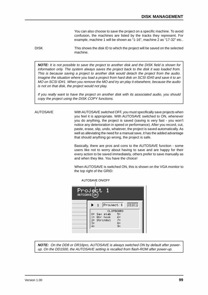
Version 1.00 99
DISK MANAGEMENT
You can also choose to save the project on a specific machine. To avoidconfusion, the machines are listed by the tracks they represent. Forexample, machine 1 will be shown as “1-16”, machine 2 as “17-32” etc..
DISK This shows the disk ID to which the project will be saved on the selectedmachine.
NOTE: It is not possible to save the project to another disk and the DISK field is shown forinformation only. The system always saves the project back to the disk it was loaded from.This is because saving a project to another disk would detach the project from the audio.Imagine the situation where you load a project from hard disk on SCSI ID#0 and save it to anMO on SCSI ID#1. When you remove the MO and try an play it elsewhere, because the audiois not on that disk, the project would not play.
If you really want to have the project on another disk with its associated audio, you shouldcopy the project using the DISK COPY functions.
AUTOSAVE With AUTOSAVE switched OFF, you must specifically save projects whenyou feel it is appropriate. With AUTOSAVE switched to ON, wheneveryou do anything, the project is saved (saving is very fast - you won’tnotice any deterioration in speed or performance). After you record, cut,paste, erase, slip, undo, whatever, the project is saved automatically. Aswell as alleviating the need for a manual save, it has the added advantagethat should anything go wrong, the project is safe.
Basically, there are pros and cons to the AUTOSAVE function - someusers like not to worry about having to save and are happy for theirevery action to be saved immediately, others prefer to save manually asand when they like. You have the choice!
When AUTOSAVE is switched ON, this is shown on the VGA monitor tothe top right of the GRID:
NOTE: On the DD8 or DR16pro, AUTOSAVE is always switched ON by default after power-up. On the DD1500, the AUTOSAVE setting is recalled from flash-ROM after power-up.

100 Version 1.00
DISK MANAGEMENT
WRITE PROTECT This parameter allows machines in the system to be write protected.When a machine is write protected, it is prevented from writing any newdata to disk. This can be used to avoid accidentally destroying valuabledata as when write protection is enabled, all record and editing functionsare prohibited.
PROJECT NAME This shows the name of the currently loaded project and is the namethat will be used when saving it. You can select a new name as describedin the next section, or automatically generate a new project name usingthe SAVE NEXT soft key (also described in the next section).

Version 1.00 101
DISK MANAGEMENT
SAVING A PROJECT WITH A DIFFERENT NAMETo save a project with a different name simply enter a suitable ten character name from a PS/2keyboard connected to the RE32. As you type, you will receive this screen:
The PROJECT NAME field is automatically ‘opened’ for naming. The bottom line will prompt you toenter the name and complete the action by pressing EXECUTE (or RETURN on the externalkeyboard).
If the name has a number in it (i.e. PROJECT 1), you can save it with a new number just bypressing any of the number keys on the numeric keypad. For example, to save PROJECT 1 asPROJECT 2, simply press 2, EXECUTE, EXECUTE.
If the name you give the project already exists, you will receive this prompt:
You should press EXECUTE to overwrite the file or EXIT to cancel the process.
Pressing EXECUTE will save the project with the new name and you will leave this page.
You can also use the SAVE NEXT key to save the project with a unique name automaticallygenerated. The basic name is retained and a unique number is appended to the end. PressingSAVE NEXT will display this prompt:
Pressing EXECUTE saves the file with a unique numeric suffix and will return you to the screenyou were in previously. EXIT will cancel the process. Please note, however, that the last fourcharacters in the name are reserved for the auto-naming process to allow for up to 9,999 uniquenames. For example, if you were to use SAVE NEXT with a file called PROJECT 1, pressing F5/F6- SAVE NEXT - would save the file as PROJEC 1. The next project you save would be calledPROJEC 2, and so on.
SAVING LOCATOR MEMORIES OR OTHER SETTINGSWhen a project is saved, if that project has locate memories associated with it, they will also besaved. A ‘settings’ file will also be saved automatically which will save the sample rate, timecodesettings, etc., relevant to the project. The status of the track select keys (PLAY, RECORD, EDIT)will also be saved along with the status of keys such ON-LINE, CYCLE, PREROLL etc., allowingyou to return to exactly the same state as you left the project when you saved it. If you have beenmaking recordings in the project you are saving and have named recordings specifically, the lastname you created will also be saved allowing you to return to the project and carry on recordingwhere you left off.

102 Version 1.00
DISK MANAGEMENT
Once you have a number of projects saved, it follows that you will want to load them again! Youmay also want to initialise the system in order to create a new project from scratch.
LOADPressing DISK will give you this screen:
Here you can see a list of projects on the currently selected disk. As is the convention in file lists,if there are projects ‘above’ or ‘below’ the screen, an upwards and/or downwards pointing arrowwill be shown ( / ). You may view and load projects on other disks by moving the cursor to theDISK field and selecting an external drive as appropriate.
To load a project, simply select the one you want and press the flashing EXECUTE key.
As the project is loaded you will see a status bar on the LCD showing you which tracks are beingloaded:
When several machines are connected to the RE32 to expand the total number of tracks available,the system will behave as if there is a single ‘multi-track’ project containing all of these tracks.However, in reality each connected machine maintains its own internal project containing data forthe tracks assigned to that machine.
When MULTI is selected in the TRACKS field, the RE32 will tell each connected machine to loadits local project and you will see the status bar change as each individual machine’s project isloaded on to the corresponding tracks.
In MULTI mode, the system assumes there is a project of the same name available on eachmachine on a disk at the same SCSI ID. If one of these individual project files cannot be found, youwill receive a message indicating which tracks failed to load:
Pressing EXECUTE will skip the tracks on the machine that failed to load and continue loadingtracks into the next machine in the system. Pressing EXIT will abort the process and return thesystem to its original state.
You can also choose to load a project on a specific machine. To do this, select the appropriatemachine in the TRACKS field. To avoid confusion, the machines are listed by the tracks theyrepresent. For example, machine 1 may be shown as “1-16”, machine 2 as “17-32” etc..
As each machine is selected, the screen will update to show the list of local projects available onthis machine. As before, to load a project, simply select the one you want and press the flashingEXECUTE key.

Version 1.00 103
DISK MANAGEMENT
In either case, once the project has been loaded you will leave the load page. The followingprompt will flash up on the screen to confirm the project is loaded:
If you have been working on a project and have not saved it, if you request the system to load aproject (or create a new one), you will now see the following prompt:
This is telling you that pressing EXECUTE will load the new project and any changes you mayhave made to the existing project will be lost. Press EXIT to abort the load so that you can save thecurrent project before continuing.
If you have a project loaded but have not made any changes, if you try to load another or create anew project, this prompt will not appear.
Whenever you load a project, if that project has locate memories associated with it, they will alsobe loaded automatically. A ‘settings’ file will also be loaded automatically which will load the systemsample rate, timecode settings, etc., relevant to the project. The status of the track select keys(PLAY, RECORD, EDIT) will also be recalled thereby returning you to exactly the same status asyou left the project when you saved it.
NOTE: When you load a project and select tracks for playback, the cues will be shown blue onthe external monitor. If, however, any are shown in a pale yellow colour, this indicates that,although a cue exists at that point in the project, the audio associated with it is not on any diskcurrently on-line.
This is not that likely to happen very often, however. An instance where it might occur is whereyou have recorded audio on to a disk separate from the project and then reloaded that projectwithout all disks attached to the system.

104 Version 1.00
DISK MANAGEMENT
CREATING A NEW PROJECTUsing NEW PROJECT, it is possible to create a new, empty project. After pressing DISK to enterthe LOAD PROJECT page, selecting NEW (F2) will take you to the following page:
As usual, you should press the flashing EXECUTE key to continue or EXIT to cancel. An emptyproject will be shown on the external monitor screen into which you may now start recording. Thenew project will be given a name automatically. You may rename this when you come to save it.
The TYPE field is used to select the type of project that will be created. The optionsavailable will depend on the format of the selected disk.
The options available are:
AKAI Create a new AKAI project on an Akai format disk
PT 4 Create a new “Protools 4” Session on a Macintosh format disk
PT 24 Create a new “Protools 24” Session on a Macintosh format disk.
As with loading a project, if the current project has been edited and those changes have not beensaved, you will receive the prompt if you try to create a new project:
You should press EXECUTE to create the new project without saving the current one or EXIT toabort the process.
NOTES REGARDING CREATING A NEW PROJECT
Whenever you create a new project, the system’s default SETTINGS file is loaded from flashROM. This allows you to configure the system as you like so that starting work with a newproject always loads the correct settings.
For example, you may always work at 44.1kHz starting at 10 hours. By zooming in to 8 tracks,setting the sample rate to 44.1kHz in the SETUP page and locating to 10:00:00:00.0 andsaving the settings to flash ROM, this is how a new project will be initialised.
Furthermore, the status of keys such as the track select keys, the ON-LINE key, the PREROLLkey, etc., is also saved and subsequently recalled when you create a new project.
Please see the section SAVING SETTINGS FILES for more information.
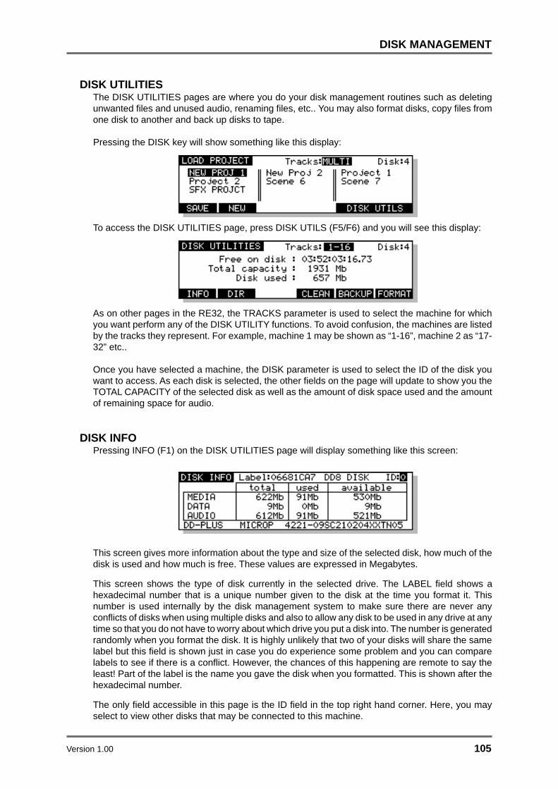
Version 1.00 105
DISK MANAGEMENT
DISK UTILITIESThe DISK UTILITIES pages are where you do your disk management routines such as deletingunwanted files and unused audio, renaming files, etc.. You may also format disks, copy files fromone disk to another and back up disks to tape.
Pressing the DISK key will show something like this display:
To access the DISK UTILITIES page, press DISK UTILS (F5/F6) and you will see this display:
As on other pages in the RE32, the TRACKS parameter is used to select the machine for whichyou want perform any of the DISK UTILITY functions. To avoid confusion, the machines are listedby the tracks they represent. For example, machine 1 may be shown as “1-16”, machine 2 as “17-32” etc..
Once you have selected a machine, the DISK parameter is used to select the ID of the disk youwant to access. As each disk is selected, the other fields on the page will update to show you theTOTAL CAPACITY of the selected disk as well as the amount of disk space used and the amountof remaining space for audio.
DISK INFOPressing INFO (F1) on the DISK UTILITIES page will display something like this screen:
This screen gives more information about the type and size of the selected disk, how much of thedisk is used and how much is free. These values are expressed in Megabytes.
This screen shows the type of disk currently in the selected drive. The LABEL field shows ahexadecimal number that is a unique number given to the disk at the time you format it. Thisnumber is used internally by the disk management system to make sure there are never anyconflicts of disks when using multiple disks and also to allow any disk to be used in any drive at anytime so that you do not have to worry about which drive you put a disk into. The number is generatedrandomly when you format the disk. It is highly unlikely that two of your disks will share the samelabel but this field is shown just in case you do experience some problem and you can comparelabels to see if there is a conflict. However, the chances of this happening are remote to say theleast! Part of the label is the name you gave the disk when you formatted. This is shown after thehexadecimal number.
The only field accessible in this page is the ID field in the top right hand corner. Here, you mayselect to view other disks that may be connected to this machine.

106 Version 1.00
DISK MANAGEMENT
DISK DIRECTORYThe Directory page allows you to view all files on a selected disk. The default is to show Projectfiles on the disks, but there are other files as well.
After selecting a machine and disk, pressing DIR (F2) on the DISK UTILITIES page will displaysomething like this screen:
Here, you can see a list of the projects on the currently selected disk. There is only one field on thispage on the very top line of the LCD:
FILE TYPE Here you can select the type of file you wish to view, rename and/ordelete. You may select PROJECTS, or LIBRARIES.
If there is a long filelist, arrows will appear to the right of the screen toindicate that there are files ‘below’ or ‘above’ the screen that you mayaccess.
Pressing SELECT DISK (F1/F2) changes the screen to allow you to select a different disk ormachine:
The parameters on the top line are:
TRACKS Here you may select the machine that is connected to the disk drive youwish to look at and work on. To avoid confusion, the machines are listedby the tracks they represent. For example, machine 1 will be shown as“1-16”, machine 2 as “17-32” etc..
DISK Here you may select the disk drive you wish to look at and work on.
Files are selected by moving the cursor keys around the list and they are highlighted when selected.
Pressing DELETE (F6) allows you to delete the item selected by the cursor.
Pressing COPY (F5) allows you to copy items from one disk to another as described in the nextsection.

Version 1.00 107
DISK MANAGEMENT
COPYING FILES/DISKSIt is possible to copy data from one disk to another. You may copy individual projects and librariesor copy the whole disk. Pressing COPY (F5) will give you this screen:
The parameters are:
TRACKS Here you may select the machine that is connected to the disks driveyou wish to copy between. To avoid confusion, the machines are listedby the tracks they represent. For example, machine 1 will be shown as“1-16”, machine 2 as “17-32” etc..
NOTE: Files can only be copied between two disks attached to the same machine.
DISK Here you may select the ‘source’ disk you are copying from.
TO DISK Here you may select the ‘destination’ or ‘target’ disk you are copying to.
COPY TYPE You may select the type of file you wish to copy in this field. You mayselect:
SINGLE FILE - this will copy a specific file as shown in the FILE TYPEand FILE NAME fields.
ALL PROJECTS - This will copy all projects on the source disk to thedestination disk.
ALL LIBRARIES - This will copy all the libraries on the source disk to thedestinations disk.
ALL FILES - This will copy all the files on the source disk to the destinationdisk.
DUPLICATE DISK - This will copy everything from the source disk to thedestination disk.
IMPORTANT NOTE: DUPLICATE WILL FIRST ERASE THE DESTINATION DISK BEFOREDUPLICATING THE SOURCE DISK TO IT.
FILE TYPE When SINGLE FILE is selected, you may select the type of file you wishto copy (i.e. PROJECT, LIBRARY or SETTINGS) in this field.
FILE NAME This parameter allows you to select the file you wish to copy.

108 Version 1.00
DISK MANAGEMENT
NOTE 1: When ALL PROJECTS or ALL LIBRARIES is selected in the COPY TYPE field, theFILE TYPE and FILE NAME fields are not shown:
NOTE 2: You cannot copy single CLIPS.
NOTE 3: It is not possible to copy from a disk to itself (i.e. from disk 0 to disk 0). You willreceive the prompt: DISK CAN’T BE COPIED TO ITSELF!

Version 1.00 109
DISK MANAGEMENT
Pressing F5/F6 initiates the COPY process. You will receive this prompt:
The selected source and the target disks are shown. The EXECUTE key’s LED will flash and youshould respond accordingly, pressing EXECUTE to confirm or EXIT to cancel. During the copyingprocess, the bottom line of the LCD will show something like this display:
A highlighting display will move across the bottom of the LCD as the file is copied. The copyingprocess is approximately 2-4 times faster than real-time (i.e. a 12 minute piece of audio will takebetween 6 and 3 minutes to copy). The time it takes to copy depends on the speed of the disks youare using (i.e. MO to MO is going to take longer than a hard disk to hard disk copy) and the natureof the files you are copying (e.g. one single 12 minute piece of audio is likely to get copied fasterthan but 48 x 15 second cues).
At any time, you may press the EXIT key to abort the copy and the whole process will be cancelled.
NOTE: In order to prevent you having an incomplete project on the destination disk, the projectselected for copying is erased from the destination disk along with all associated audio whenyou press EXIT. This may take a second or two.
If you try to copy a project or library to another disk and a project or library of exactly the samename exists on the target disk, you will receive this prompt:
As this will erase the project and all its audio on the target disk, you are given a second level ofprompting for safety’s sake:
The EXECUTE key will flash and you should respond accordingly pressing EXECUTE to proceedand EXIT to cancel but please be careful because, as the prompt advises, it is not possible to undothis action.
The same process is used for disk duplication.
You may leave the COPY FILE page at any time by pressing EXIT.

110 Version 1.00
DISK MANAGEMENT
**IMPORTANT NOTES REGARDING COPY **
The COPY process copies the project/library and all referenced audio across to the targetdisk. This is to prevent audio becoming detached from the project or library with which it isassociated. However, the copying process only copies across the audio associated with thecues plus a 10% ‘handle’ either side of the cue.
For example, imagine that you have a 5 minute continuous recording of assorted sound effectsand you have used a mere 30 seconds of it in a project you have chosen to copy. On thesource disk, that cue is referencing the full 5 minutes of audio (but only playing the relevant 30seconds of it in the project). When you copy the project across, it will only copy the 30 secondsection you are using in the project (plus 3 a second ‘handle’ either side) NOT the full fiveminute piece of audio it originally came from. You may find therefore, that when you copy aproject from one disk to another, the project on the target disk will use less disk space than theone on the source disk.
However, please note one important restriction regarding copying individual projects and librariesseparately to another disk. Because the audio is copied each time you individually copy aproject or a library, this will take up extra disk space on the destination disk. This will happeneven when you copy two similar projects that reference the same audio.
For example, imagine you have two projects PROJECT 1 and PROJECT 2 on DISK 0 andboth projects use exactly the same audio (PROJECT 2 being just a slight variation on PROJECT1). If you were to select SINGLE FILE as the file type and individually copy each project toDISK 1 separately, you will find that the audio is duplicated, using up disk space. In this case,you should use ALL PROJECTS - this would copy both projects but would only copy the audioonce.
In the event of you having, say, five projects on DISK 0 all using the same audio but you onlywant to copy PROJECT 1, 2 and 5 to DISK 1, select ALL PROJECTS and copy all five projectsacross in one operation (and hence only one version of the audio) and then, on DISK 1, deleteprojects 3 and 4.
The same is true when copying libraries.

Version 1.00 111
DISK MANAGEMENT
DELETE FILESIn the disk DIRECTORY page, you can delete projects and/or libraries depending on the selectionmade in the FILE TYPE field. First select the type of file you wish to delete in the FILE TYPE fieldand then move the cursor to the file you wish to delete. Pressing DELETE will give you this prompt:
The EXECUTE key’s LED will be flashing and you should press EXECUTE (YES) or EXIT (NO/CANCEL) accordingly. As the prompt tells you, there is no undo for this so please check carefullythat the correct file is selected for deletion before proceeding. If in any doubt at all, press EXIT toabort.
If you press DELETE (F6) and the cursor is not on a file (i.e. it is on the DISK or FILE TYPE fields),the screen will pop-up the prompt:
This prompt will appear for a few seconds. You should move the cursor to the file you wish todelete and press F6 (DELETE) again.
If you try to delete a project that is currently loaded, you will receive this prompt:
You should either load another project or create a new one and then return to the DISK page todelete the project you originally wanted to delete.
If you have deleted any files, when you leave the DIRECTORY page, you will receive this prompt:
When a project or library is deleted, the audio associated it with not deleted at the point of deletion.This may seem a bit odd but the reason for this is that if audio was deleted when you pressedEXECUTE, every time you delete a file, the system would have to go through a lengthy searchprocess to check if the audio associated with that file is referenced anywhere else (i.e. in otherprojects and/or libraries) and this could take some time.
As a result, to make the deletion process quick, only the file itself is deleted. Then, when you cometo leave the DISK page, you are offered the choice of ‘cleaning’ up the disk. What this means isthat the machine will search any connected disks and look to see if the audio associated with thefiles you have deleted is used anywhere else. If any part of it is referenced by any other projectsand/or libraries, the audio will not be deleted. If, however, the audio associated with the file(s) youhave deleted is not used by any other project and/or library, the audio will be erased from disk,thus freeing up extra disk space.
To save yourself some time, if disk space is not a problem, you can choose to ignore this promptby pressing EXIT and you can come back to this when it’s more convenient. If you wish to proceedand erase any unreferenced audio, press the flashing EXECUTE key (see later - CLEANUP DISK).

112 Version 1.00
DISK MANAGEMENT
RENAMING FILESIt is also possible to rename files in the DIRECTORY page by placing the cursor over the file youwish to rename and typing a new name from a PS/2 keyboard connected to the RE32. As you starttyping, you will receive this prompt:
When you have finished, press RETURN (or EXECUTE on the RE32’s front panel) to completethe name and RETURN again to enter the name. Press ESC(ape) to abort the naming process onthe computer keyboard (or EXIT on the RE32’s front panel).
If you try to rename a project that is currently loaded, you will receive this prompt:
You should either load another project or create a new one and then return to the DISK page torename the project you originally wanted to rename.
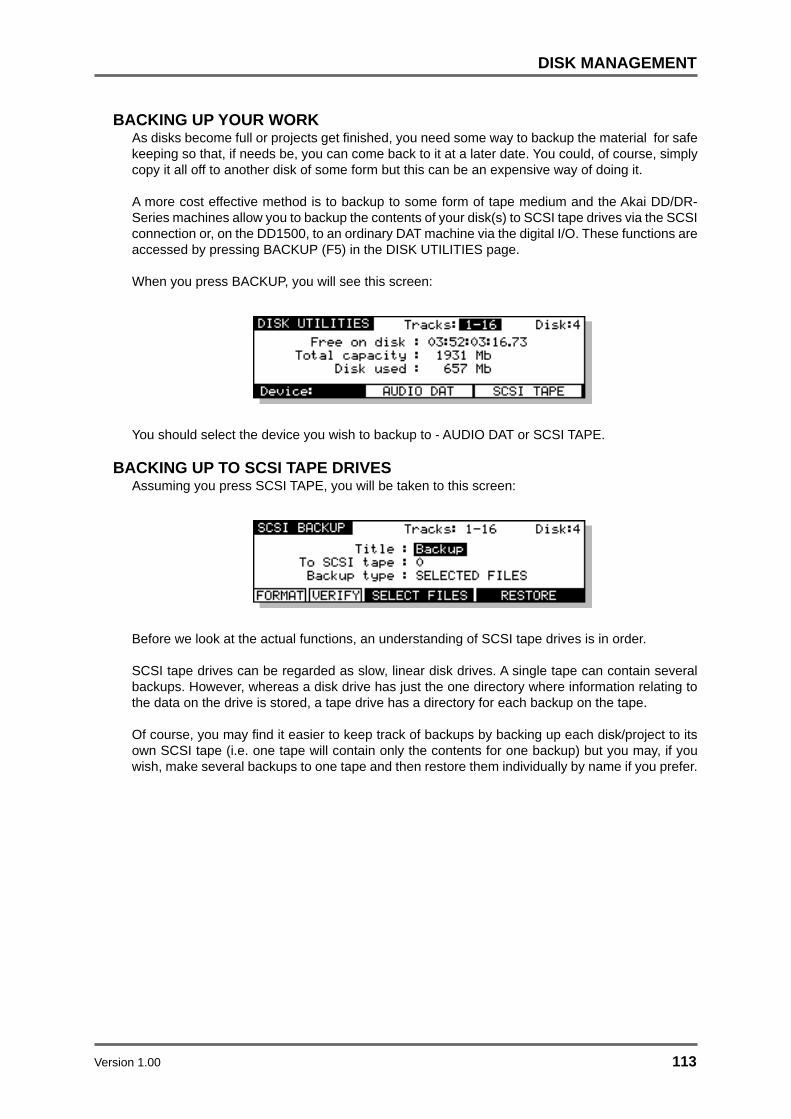
Version 1.00 113
DISK MANAGEMENT
BACKING UP YOUR WORKAs disks become full or projects get finished, you need some way to backup the material for safekeeping so that, if needs be, you can come back to it at a later date. You could, of course, simplycopy it all off to another disk of some form but this can be an expensive way of doing it.
A more cost effective method is to backup to some form of tape medium and the Akai DD/DR-Series machines allow you to backup the contents of your disk(s) to SCSI tape drives via the SCSIconnection or, on the DD1500, to an ordinary DAT machine via the digital I/O. These functions areaccessed by pressing BACKUP (F5) in the DISK UTILITIES page.
When you press BACKUP, you will see this screen:
You should select the device you wish to backup to - AUDIO DAT or SCSI TAPE.
BACKING UP TO SCSI TAPE DRIVESAssuming you press SCSI TAPE, you will be taken to this screen:
Before we look at the actual functions, an understanding of SCSI tape drives is in order.
SCSI tape drives can be regarded as slow, linear disk drives. A single tape can contain severalbackups. However, whereas a disk drive has just the one directory where information relating tothe data on the drive is stored, a tape drive has a directory for each backup on the tape.
Of course, you may find it easier to keep track of backups by backing up each disk/project to itsown SCSI tape (i.e. one tape will contain only the contents for one backup) but you may, if youwish, make several backups to one tape and then restore them individually by name if you prefer.

114 Version 1.00
DISK MANAGEMENT
FORMATTING A TAPE FOR BACKUPBefore you can perform a backup, you must first format the tape so that the tape is set up toreceive files and digital audio data. This done using the FORMAT key.
To format the tape, select the appropriate SCSI ID for the tape drive in the TO SCSI TAPE field. Aswith disk drives, the tape drive must not share the same SCSI ID as any other SCSI device on thebuss. Once selected, press the format key. You will see this screen:
** FORMATTING THE TAPE WILL PERMANENTLY DESTROY ITS CONTENTS **
PLEASE BE CAREFUL BEFORE PROCEEDING
Because of the potential danger of accidentally formatting an existing tape, you must pressSHIFT+EXECUTE to proceed. During the format, you will see the message “FORMATTING TAPE.PLEASE WAIT” pop up on the screen during the process. Once the process is complete, you willsee the message “FORMAT COMPLETE”. The tape is now ready for use.
NOTE 1: The format should not take long under normal circumstances (15 seconds or so) butif the tape has been used several times before, you may find it takes longer as the system mayneed to check the tape to make sure it is suitable for use. Under extreme circumstances, itmay need to check the entire tape and so could take some time. If this is the case and theformatting seems to be taking a long time, you can press EXIT to abort the formatting process.
To avoid this, it is recommended you always use new, unused tapes. It is also not a good ideato use tapes that may have been used to backup material from some other system (for example,a PC or a Macintosh™ computer or (heaven forbid!) some other disk recorder.
NOTE 2: If you receive other messages such as DRIVE NOT READY or DRIVE BUSY, thenthere is a problem with the cable and/or the drive. Please check both. Is the drive switched on?Is there a tape in the drive? Are the cables connected securely? Is the SCSI buss terminatedcorrectly? If everything seems correct but the problem persists, try moving the tape driveelsewhere in the buss (i.e. move from the end of the chain to the middle or vice versa). If theproblem still persists, contact you AKAI professional dealer.
If a message such as THE SELECTED SCSI ID IS A DISK DRIVE is shown, this indicates youhave selected the wrong SCSI ID in the TO SCSI TAPE field. Please take the appropriatesteps.

Version 1.00 115
DISK MANAGEMENT
The fields on the SCSI BACKUP page are:
TITLE You may give the backup a title of up to ten characters. This will bestored in the SCSI tape’s directory and you will be able to use this nameto selectively restore the backup in future in the event of you archivingseveral different backups to tape. Naming is done in the usual mannerby typing on the external PC keyboard. If you do not specifically give it aname, the default name BACKUP will be used.
DISK This selects the disk that will be backed up to the SCSI tape drive.
TO SCSI TAPE This selects the SCSI ID of the tape drive.
NOTE: As with any SCSI device, the tape’s SCSI ID should be unique and should not sharethe same ID as another device on the SCSI buss.
BACKUP TYPE This selects what will be backed up to the SCSI tape. You may select:
SELECTED FILES You may, via F3/F4, select specific files tobackup. These may be projects or libraries.
ALL PROJECTS You may backup all the projects on theselected disk.
ALL LIBRARIES You may backup all the libraries on theselected disk.
ALL PROJS & LIBS You may backup all the projects and all thelibraries on the selected disk.
ENTIRE DISK You may backup everything on the disk.

116 Version 1.00
DISK MANAGEMENT
BACKING UP SELECTED FILESChoosing SELECTED FILES in the BACKUP TYPE field will show this screen:
SCSI BACKUPSCSI BACKUP
FORMAT
Tracks: 1-16 Disk:4
Backup type : SELECTED FILESBackup type : SELECTED FILES
VERIFY SELECT FILESSELECT FILES RESTORE
From disk : From disk : ()To SCSI tape : To SCSI tape : ()
Title : Title : Backup
To actually select the files, press SELECT FILES (F3/4). You will see something like this screen:
You can select PROJECT or LIBRARY in the TYPE field, You may select a disk to backup in theDISK field.
To select the file you wish to backup, move the cursor to the file name and press the DATA + key.A small block appears to the left of the file name to indicate it is selected for archiving. For example:
In this case, PROJECT 1 is selected for backup. The bottom of the LCD will show how many filesare selected. In this case, just one.
You may also select several files for backup in this way. For example, by moving the cursor todifferent file names and pressing the DATA + key, you may end up with something like this:
In this example, PROJECT 1, TV PROJ 3, SCENE 6, TV PROJ 1, TV PROJ 2 and V2 PROJ 3 areall selected for backup. The bottom of the LCD shows how many files are selected.
As in other disk pages, arrows appear to indicate files that are ‘off-screen’. Use the CURSOR UP/DOWN keys to scroll through the list.
You may also select ALL the files shown on this page simply be pressing SHIFT and the DATA +key.

Version 1.00 117
DISK MANAGEMENT
NOTE: This is the same as selecting the ALL PROJECTS or ALL LIBRARIES or ALLPROJS&LIBS option in the SCSI BACKUP TYPE field. However, whilst this may seem like anunnecessary duplication of a function, it might be useful if you want to backup all projectsexcept one or two - i.e. press SHIFT and DATA + and then use DATA - to de-select those fewfiles which you do not wish to backup. On a busy disk with many projects/libraries to backup,this may be more convenient than individually ‘marking’ every file you want to backup.
Files selected by mistake can be de-selected using the DATA - key. For example, moving thecursor back to SCENE 6 on this example and pressing the DATA - key would de-select it:
At the point you press DATA -, you will see the number of files selected decreases by one (in thiscase, only 5 files are now selected).
Once you have selected the file(s) you want to backup, press EXIT to return to the main SCSIBACKUP page and proceed with the backup.
BACKING UP ALL PROJECTS AND/OR LIBRARIESIf you have selected ALL PROJECTS, ALL LIBRARIES or ALL PROJS & LIBS, all you need to dois press the flashing EXECUTE key. All the projects and/or libraries on the disk selected in theFROM DISK field will be backed up. If any projects and/or libraries use audio from any otherconnected disks, these too will be backed up to the destination SCSI tape.
The exact amount of time the backup will take depends on the amount of material being backedup. Backup speed is approximately five times real-time (i.e. ten minutes of audio will takeapproximately 2 minutes to backup).
BACKING UP AN ENTIRE DISKAs well as selectively backing up chosen files or backing up all projects and/or libraries, you mayalso make a duplication of the disk by selecting ENTIRE DISK in the BACKUP TYPE field.
NOTE: Although ENTIRE DISK may seem the same as ALL PROJS & LIBS, there is a difference.ALL PROJS & LIBS will backup everything from the selected disk but it will also backup anyaudio from other disks that are used in the projects and/or libraries being backed up. ENTIREDISK, on the other hand, only backs up the audio on the selected disk, not any audio referencedon other disks. ALL PROJS & LIBS, therefore, is more suitable for backing up your work whilstENTIRE DISK is a better selection to make if you just want to make a safety copy of a disk.

118 Version 1.00
DISK MANAGEMENT
PERFORMING THE BACKUPRegardless of the backup type you have selected, to actually perform the backup, simply pressthe flashing EXECUTE key. You will see this screen:
Here, the system is getting the tape ready for the backup. First of all, it will look at the tape’sdirectory to make sure that there is no backup of the same name. If a backup of the same nameexists on the tape, you will receive this message:
In this case, press ABORT and give the backup a new name and try again (i.e. press EXECUTE)or insert a new tape and press CONTINUE.
NOTE: You will need to specifically go to your tape drive use the front panel EJECT key toeject the current tape and insert a new one.
Assuming everything is ok, the system will then wind the tape to the first available space where itcan write data. If the tape is a new, freshly formatted tape, this will be quite quick but if the tapecontains several backups already and these contain a lot of data, it may take a while to wind to thefirst available area of the tape suitable for backing up to.
NOTE: You may see other messages pop up. These will be momentary - don’t worry aboutthese.
Once a suitable position on the tape has been located, the backup will begin and you will seesomething like this screen as the backup takes place:
The screen shows the progress of the backup as it takes place and this is expressed as a percentageand as a highlighting bar. The percentage in the top line shows how much of the individual file hasbeen backed up whilst the percentage in the bottom line shows how much of the entire backup hasbeen done.
If any of the selected files use audio from any other connected disks, these too will be backed upto the destination SCSI tape (except in the case where ENTIRE DISK is selected). During theprocess, you may abort the backup by pressing the EXIT key at any time.
The exact amount of time the backup will take depends on the amount of material being backedup. Backup speed is approximately five times real-time (i.e. ten minutes of audio will takeapproximately 2 minutes to backup).

Version 1.00 119
DISK MANAGEMENT
At the end of the backup, you will see this screen:
The system will rewind the tape to the start in readiness for the next backup. Exactly how long thistakes depends on the amount of data on the tape.
Finally, you will see this screen display:
Press any key to continue.

120 Version 1.00
DISK MANAGEMENT
VERIFYING A BACKUPOnce you have performed a backup, you may like to verify it to check that everything has backedup correctly. This is done by pressing the VERIFY key followed by EXECUTE. You will see thisscreen:
You should press EXECUTE to continue, EXIT to abort. As the verification takes place, you willsee this screen:
You may abort the process at any time by pressing the EXIT key.
NOTE: The VERIFY process does a comparison of what is on the source disk and what is ontape and the idea is that the disk contents and the tape contents must be identical for theverification to be successful. Because of this, the VERIFY process is best done immediatelyafter a backup. In this case, you should have no problems as the two media should haveidentical contents. If, however, you make a new recording on the source disk or delete anythingfrom the source disk after the backup, the contents of both media will not be the same and soyou will receive messages such as “FILE XXXX MATCH NOT FOUND”. This is telling you thateither it has found something on the disk which does not correspond to what is on tape (i.e.you may have made a new recording) or it has found something on tape which it cannot find onthe disk (i.e. you have maybe deleted something off disk).
It is not essential that you run the VERIFY process after a backup but, bearing in mind the potentiallyserious implications of a faulty backup, it is highly recommended. However, you will please notethat the VERIFY process will take about two or three times as long as the backup took so whilst it’srecommended you verify your backups, you might like to do it during a ‘quiet moment’.

Version 1.00 121
DISK MANAGEMENT
RESTORING A BACKUPTo restore data, in the DISK UTILS page press BACKUP. You will see this screen:
Select SCSI TAPE. You will see this screen:
Press RESTORE (F5/6). You will see this screen:
SCSI RESTORESCSI RESTORE Tracks: 1-16 Disk:4
Restore type : SELECTED FILESRestore type : SELECTED FILES
From SCSI tape : From SCSI tape : ()
Title : Title : Backup
SELECT TITLESELECT TITLE BACKUPSELECT FILESSELECT FILES
As you can see, this is basically the reverse of the SCSI BACKUP page. The fields are:
DISK Selects the disk the data will be restored to.
TITLE Selects/shows the name of the backup you wish to restore.
FROM SCSI TAPE Selects the tape drive the data will be restored from.
RESTORE TYPE Selects what will be restored to the disk.

122 Version 1.00
DISK MANAGEMENT
PERFORMING A RESTORETo perform the restore, select the disk you wish to restore to. Of course, make sure the correctSCSI ID is set for the tape drive in the FROM SCSI TAPE field.
You need to enter the name of the backup you wish to restore. In the simplest example, the tapeyou are restoring from may contain just one backup that uses the default name BACKUP. In thiscase, you can just press EXECUTE to start the restore. If a name other than the default was used,if you know the EXACT name (bearing in mind upper and lowercase characters and spaces, etc.),type the name in the TITLE field. If you are not sure what is on the tape, press SELECT TITLE (F1/F2) to see the names of the backups on the tape. Pressing SELECT TITLE will show this screen:
Depending on the number of backups on the tape, it could take a while to search the tape for thedifferent titles. If it contains only one backup, the search should not take long but search time willincrease according to the number of backups on the tape. Press EXECUTE to continue. You willsee this screen:
After a while, you will be taken to this screen:
Here, you see a list of all the backups on the tape and the number of files (cues/clips) containedwithin them. In this case, there are just three backups. If more than five backups exist on the tape,up/down arrows will appear to indicate that there are items ‘off screen’ that you may select. Movethe cursor to the one you want to restore and press EXECUTE. The backup will be selected andyou will be taken back to the main SCSI RESTORE page:
SCSI RESTORESCSI RESTORE Tracks: 1-16 Disk:4
Restore type : SELECTED FILESRestore type : SELECTED FILES
From SCSI tape : From SCSI tape : ()
Title : Title : Animals LbAnimals Lb
SELECT TITLESELECT TITLE BACKUPSELECT FILESSELECT FILES
The easiest restore to perform is when a tape has just one backup on it. In this case, simply selectALL PROJS & LIBS and press EXECUTE. Regardless of the type of backup you performed on thistape, any projects and libraries found on the tape will be restored.
Similarly, if the tape contains just one backup of only libraries, you can still use the ALL PROJS &LIBS selection - if the system doesn’t find any projects, it will ignore this and will restore only thelibraries it finds. The same would be true of projects. If the tape only contains projects, eventhough ALL PROJS & LIBS is selected as the restore type, if it can’t find any libraries, it will justcontinue, restoring only the projects.

Version 1.00 123
DISK MANAGEMENT
You can also select ENTIRE BACKUP as the restore type and this will restore everything in theselected backup.
You may also select to restore only libraries by selecting ALL LIBRARIES. In this case, even if abackup contains projects, these will be ignored. Likewise, if you select ALL PROJECTS, onlyprojects found will be restored and any libraries in the backup will be ignored.
You may also specifically select the files you want to restore by selecting SELECTED FILES. Toactually select the files for restore, press SELECT FILES (F3/4). First, you will see this screen:
The system needs to read the directory on the tape to know what files are contained in it. PressEXECUTE to proceed (or EXIT to cancel). You will see this screen:
Depending on the complexity of the backup, after a short while, you will be taken to something likethis screen:
Here, you may select the files in the backup you wish to restore (if you have used SELECTEDFILES as the backup type, you will already be familiar with this and operation is the same). Movethe cursor to the file you wish to restore and press the DATA + key. A small block will appearalongside the filename to indicate that it has been selected:
The number of files selected for restore will be shown. Continue to mark the files you wish to selectin this way. Press EXIT to return to the main SCSI RESTORE page.

124 Version 1.00
DISK MANAGEMENT
Regardless of the type of restore you have selected2 , the process is initiated by pressing theEXECUTE key. You will see this screen display:
Followed by this screen:
After a short while (depending on how many cues are in the backup), you will see this screen:
You will see the backup being restored onto the selected disk. The percentage figures will changeas the restore progresses and highlighted bar will move across the bottom of the LCD to furtherindicate progress.
You will then see this display:
What the system is doing here is ‘fixing up’ all references to the audio data that has just beenrestored so that any projects and/or libraries that may use the cues/clips that have just beenrestored will play correctly. The percentage will change to indicate progress and the exact lengthof time it takes depends on the mount of ‘fixing up’ the system has to do (i.e. how many differentplaces the audio you have restored is used).
Finally, you will see this screen display:
2 There is a difference when ENTIRE BACKUP is selected. This will be explained later.

Version 1.00 125
DISK MANAGEMENT
If, when you perform the restore, a library or project on the disk you are restoring to shares thesame name as one being restored, you will see this prompt:
Pressing ABORT (F3) will abort the whole restore process. You will see this screen:
If you press NO (F4), the restore will proceed as described on the preceding page but a newproject or library will be created with a new automatically numbered name. Using the above example,pressing NO at the OVERWRITE prompt would create a new library called ANIMALS 1 (or someother suitably numbered library of that name).
Pressing YES (F5/6) will cause the restore to proceed as normal and as described on the previouspage and the selected library on disk will be overwritten.
**Be careful that you don’t overwrite a valuable project or library **There is no means to retrieve or salvage it once it has been overwritten.
RESTORING THE ENTIRE BACKUPRestoring an entire backup is essentially the same as the other types of restore except that whenyou press EXECUTE, you are prompted thus:
You have the option to completely wipe the selected disk prior to restoring data back onto it.Respond by pressing NO or YES/EXECUTE as appropriate (or EXIT to abort).
*** BE VERY CAREFUL WITH YOUR SELECTION ***
If you select YES, the data you erase cannot be retrieved or salvaged.

126 Version 1.00
DISK MANAGEMENT
NOTES ABOUT BACKUP/RESTOREWhen backing up data to disk, there are a few things you should be aware of.
• When ALL PROJECTS, ALL LIBRARIES, and ALL PROJS & LIBS are selected as the BACKUPTYPE, if any projects and/or libraries use audio from other disks, this audio will also be backedup. However, when you come to restore this data, the material from the other disks will berestored to the single ‘destination’ disk selected in the TO DISK field. For example:
SFX
MUSIC
DIALOGUE
ID#0
ID#1
ID#2
BACKUP
Tape Drive
SFX, MUSIC and DIALOGUEID#0
ID#1
ID#2
RESTORE
Tape Drive
In the above example, SFX, music and dialogue from disk IDs 0, 1 and 2 are backed up to tapebut these will be restored to the disk selected (in this example, Disk ID#0)
In other words, you should ensure that the destination disk for the restore is large enough toaccommodate all the material (the RE32 will inform you if it isn’t).
• If the data you are trying to backup to tape is larger than that which the tape can hold (or if thereis already quite a bit of data on the tape), the backup will be done across two or more tapes.The RE32 will prompt you if this is the case and will tell you to insert another tape. If the tape isunformatted and unsuitable for use, you will be prompted to format the tape whereupon thebackup will continue.
Of course, there is nothing wrong with this practice but it may get awkward trying to keep trackof your backups and so, in view of this, to avoid this situation, you might prefer to use new,freshly formatted tapes when attempting a backup.

Version 1.00 127
DISK MANAGEMENT
SUGGESTIONS FOR BACKUP/RESTORE• Try not to re-use tapes. They are relatively inexpensive to buy and potentially carry very expensive
data so it is not wise to economise.
• Do not use ordinary audio tapes unless you’re really stuck as tapes made specifically for backupwill be more reliable.
• Try to organise your backups sensibly to make restoring them easier.
• In much the same as in ‘the old days’ of 1/4 inch and multi-track tapes, try to ensure that thetape box is well labelled. Include any relevant information regarding the data stored on it.Include dates, client names and anything else you think appropriate that will make recognitionof the material and the restore that much easier. Remember! It might not be you who restoresit but somebody completely unfamiliar with the data.
• Store and treat the tapes carefully. Just because the media is small doesn’t mean it doesn’tdeserve the same respect as a hefty 10” reel of master tape.
• Naturally, keep backup tapes away from magnetic sources such as monitor speakers, etc..
• If you have to send the backups anywhere, make a copy of them first.
• When sending tapes anywhere, package them well in a suitable padded envelope or box andwrap the tape in aluminium foil to help prevent damage from stray magnetic interference.
• Always write protect the tape. It may be a nuisance should you try to backup to it and get anerror message but this is better than accidentally formatting it or overwriting existing backups.
• If you are travelling abroad with your backups, take them as hand luggage. Although the X-raymachines are supposed to be safe, you may be able to persuade airport security to have themmanually inspected (normal luggage is often subjected to high power X-ray inspection that maynot be too kind on the tape). Leave a copy at home just in case.
• Keep backups away from liquids, etc..
• Do not leave tapes lying around in vehicles, especially on hot days.
128 Version 1.00
DISK MANAGEMENT
TAKING CARE OF YOUR TAPE DRIVETape drives need to be taken care of quite carefully. You should refer to your drive’s operator’smanual for more details on this but some general guidelines are:
• As routine maintenance, the heads should be cleaned after every 25 hours or so of use. Basically,clean the heads regularly.
• To clean the heads of your drive, only use the head cleaner recommended in your drive’sdocumentation.
• If your drive is a SCSI DAT drive, do not use standard audio DAT head cleaners.
• If you are using a SCSI DAT drive, avoid using audio DATs. Use only those tapes recommendedby your drive’s manufacturer.
• Keep the drive in a dust free environment. Dust on the heads could lead to a loss of dataintegrity and failed backups/restores.
• Don’t smoke near the tape drive. This can really clog the heads!
• Do not try to use the tape drive if you move it from environments of differing temperatures andhumidity. Moisture on the head as a result of condensation could damage the tape. If you mustmove the drive from one place to another, turn it on and leave it for a while before attempting touse it to give any condensation a chance to evaporate. Consult your drive’s operator’s manualfor details on this.
• If you must manually eject the tape, there can be a few seconds delay before the tape isejected. Do not power down the drive in this period as you may damage the heads and/or thetape.
Also, don’t forget to pay attention to the normal considerations of SCSI:
• Make sure the total length of the buss doesn’t exceed 6 metres.
• Make sure the correct devices are terminated (this should be the first and last in the chain withall other being unterminated).
• Make sure that no devices on the buss share the same SCSI ID.
Etc..

Version 1.00 129
DISK MANAGEMENT
ARCHIVING DATA TO DATSelecting AUDIO DAT in the BACKUP page takes you to this page:
Here you may backup the contents of your disk to a normal DAT machine via the digital audio I/O.
The parameters in the ARCHIVE page are:
DISK This selects which disk you will archive.
ARCHIVE TYPE Here you may select the type of item you wish to archive. The optionsare:
SINGLE FILE This allows you to select a single file forarchiving. When SINGLE FILE is selected,FILE TYPE and FILE NAME fields appearbelow the ARCHIVE TYPE field where youmay select the type and the file for archiving.
The SINGLE FILE option is very convenientfor archiving single projects to DAT.
ALL PROJECTS This will archive all projects and any audioassociated with them.
ALL LIBRARIES This will archive all libraries and any audioassociated with them.
ALL FILES This will archive all projects and libraries andany audio associated with them. It will notarchive any unreferenced audio.
ALL LIBRARIES This will archive all libraries and any audioassociated with them.
DUPLICATE DISK This makes a complete copy of everything onthe disk to the DAT.
NOTE: When ALL PROJECTS, ALL LIBRARIES, ALL FILES and DUPLICATE DISK areselected, the FILE TYPE and FILE NAME fields are not shown.

130 Version 1.00
DISK MANAGEMENT
If the selected machine is a DD1500, pressing DAT OPTIONS (F1/F2) will give this screen display:
Here you may select which of the digital I/Os you will use for the archive/restore. For restoring, youmay choose between DIG A or B (or if optional digital I/Os are fitted, DIG C or D) and for archiving,you may select MIX A or MIX B outputs.
In both of these screens, you may also set the tape length of the DAT you are restoring to and youmay choose between DAT 30 (30 minute tapes) to DAT 180 (3 hour tapes). The archive processuses the stereo capacity of the DAT tape so a DAT 120 can hold 4 hours worth of material (you cando your own maths for the other tape lengths!).
To perform the archive, insert a blank DAT tape into the DAT recorder and make sure it is rewoundto the start. Put the DAT recorder into ‘record pause’. Get the selected machine ready for archive,‘unpause’ the DAT and then press ARCHIVE (F5/F6). The archiving process will begin.
If the tape runs out during the archive, you will be prompted to insert another.
The time taken to archive is just a little longer than real-time (i.e. one hour of material will take justover one hour to archive). However, please note the capacity of DAT for archiving purposes. A DAT60 can hold approximately 600Mb of data making it a bit too small to archive one side of a 1.3GbMO disk (650Mb - approximately 2 hours of audio at 44.1kHz) but because a DAT 90 can holdapproximately 900Mb you could easily archive one side of a 1.3Gb MO disk to such a tape. A DAT120 could be used to archive a 1Gbyte hard disk. Larger hard disks will need to be archived overseveral tapes and you may prefer to archive your projects and/or libraries individually in this caseas you can organise the order you want the items archived and decide which tapes you want themon. Furthermore, with single files archived in this way, when you come to restore, you don’t have todo the full restore but you can selectively restore projects you are interested in.
** IMPORTANT NOTE ABOUT RESTORING SINGLE ITEMS **
YOU CANNOT RESTORE A SINGLE PROJECT/LIBRARY TO A DISK TO ADD TOOTHER PROJECTS/LIBRARIES ON THAT DISK!!!
The restore process first erases the disk and then restores the audio onto the disk. In otherwords, you cannot make a compilation of projects and libraries from different archive tapes
onto one disk because each time you restore an archive, the disk will be erased.
Please ensure that you use a blank disk (or one you are happy to erase) when restoring.
AKAI professional CANNOT BE HELD RESPONSIBLE FOR DATA LOST IN THIS WAY.
Version 1.00 131
DISK MANAGEMENT
NOTES ABOUT ARCHIVING TO AUDIO DAT
• If your disk is quite large and has a lot of material on it, then larger tapes are recommended.You will note, however, that if the tape runs out during the archive process, you will beprompted to insert another tape. It is important, therefore, to set the tape length field tomatch that of the actual tape you are using otherwise the archive process will go wrong.
• When archiving across several tapes, you must use blank DAT tapes that are rewound tothe very start of the tape when archiving. Failure to do so will cause problems. For example,if you are using a 120 tape and have selected DAT 120 in the ARCHIVE TAPE LENGTHfield, but start it half way through the tape, the system will archive for a setting of DAT 120(i.e. it is set to archive for two hours and then prompt you) but, of course, the tape will haverun out after an hour, the system will not know this and will continue to archive as though aDAT 120 tape is being used.
• DAT180 tapes can be used but, because the tape is rather flimsy, please use with caution.
• Because DCC (digital compact cassette) and MiniDisk use data compression, althoughyou can appear to be archiving successfully to either of these two mediums, the restore willfail. AKAI professional cannot be held responsible for the loss of data archived to DCC orMiniDisk.
• When data is archived, data files (i.e. projects, libraries, etc.) are written several times tothe DAT tape to overcome the remote possibility of dropouts, tape damage, etc. (the audiois only written once to the tape, however). Whilst every effort has been made to ensurereliable archiving and restoring of data, copying to another disk is more reliable and istherefore recommended. AKAI professional cannot be held responsible for data lost whenarchiving to audio DAT.
• When data is archived to DAT, please ensure that the tape is stored carefully and in itsproper case.
• When large amounts of data are archived across several DAT tapes, try to keep all thetapes together for a successful restore at a later date.
• Label the tapes carefully - it will make restoring them that much easier.
• It is a good idea to ‘write protect’ the DAT tape.
• Do not leave the tape anywhere where it may be ruined by accidental spillage of liquids.
• Do not leave the tape anywhere where it may be affected by dust.
• Do not leave the tape anywhere where it may be affected by adverse heat (i.e. in vehicles,near to radiators or other such heaters, etc.).
• Do not leave DAT archives close to strong magnetic fields (high powered speakers, TV/computer/video monitors, etc.).

132 Version 1.00
DISK MANAGEMENT
RESTORING FROM DATPressing RESTORE in the ARCHIVE page will show this screen display:
Here you may restore the contents of a DAT back to the disk via the digital audio I/O.
To connect your DAT machine, connect the digital output of the DAT machine to the digital inputsof the selected Akai DD/DR series machine (you can set which one will be used in the DAT OPTIONSpage).
The DISK parameter allows you to select which disk you will restore to.
DAT OPTIONS (F1/F2) has the same function in RESTORE as it does in ARCHIVE. Please referto ARCHIVE for details on the DAT OPTION page.
With a DR16pro, you may also choose to restore from an Alesis ADAT machine using the optionalADAT interface card. If the selected machine is a DR16pro, pressing DAT OPTIONS (F1/F2) willgive this screen display:
Here, the ARCHIVE/RESTORE TYPE field allows you select MULTI-OPTION allowing multi-channelaudio restore via a digital audio option card from an Alesis ADAT.
To restore an archive, insert the appropriate tape into the DAT machine and rewind it so that it is atthe start of the tape. Press RESTORE (F3/F4). You will receive this prompt:
Because restoring will erase everything on the disk selected in the DISK field, this extra prompt isshown. Furthermore, to make accidental erasure even more difficult, you must pressSHIFT+EXECUTE to proceed. If you have the slightest doubt about restoring at this point(proceeding will erase EVERYTHING off the selected disk!!!!) press EXIT to abort this prompt.
Assuming you wish to proceed, press SHIFT+EXECUTE. The system will wait and you shouldstart the DAT machine. The restore will take place. Once you press SHIFT+EXECUTE, be warned- there is no going back! The disk will be erased and the restore will start.
** IMPORTANT NOTE ABOUT RESTORING **
THE RESTORE PROCESS FIRST ERASES THE DISK AND THEN RESTORES THEAUDIO ONTO THE DISK. PLEASE ENSURE THAT YOU USE A BLANK DISK (OR ONE
YOU ARE HAPPY TO ERASE) WHEN RESTORING DATA FROM DAT.
AKAI professional CANNOT BE HELD RESPONSIBLE FOR DATA LOST IN THIS WAY.
As with archiving, the restore will take a little longer than real-time (i.e. an hour’s worth of materialwill take just over an hour to restore. If the archive contains many very short clips, then archivingwill take a bit longer).

Version 1.00 133
DISK MANAGEMENT
CLEANUP DISKCLEANUP DISK allows you to clear out redundant recordings and so save valuable disk space.Pressing CLEAN (F4) from the DISK UTILITIES page shows this screen:
It is possible to have a disk full of unreferenced audio files. These are pieces of audio that have noassociation with any project or library. These are usually created when recording. For example,you make one recording and make a mistake. You drop in again over that, recording a new pieceof audio. If the original recording is not in a library or another project, the audio associated with theoriginal cue you recorded of it has become ‘unreferenced’ and is taking up disk space needlessly.Of course, if you keep recording over and over again on the same spot, you can fill your disk upfairly quickly. Also, if you delete a cue from a project or a clip from a library, you can end up withunreferenced audio. Another way audio can become ‘unreferenced’ is if you make a recording andthen don’t save the project. The functions in the CLEANUP page allow you to deal with this.
The CLEANUP functions are:
CLEANUPThis will only erase unreferenced audio but will not ‘top and tail’ the cues that are valid. However,because CLEANUP keeps all the audio that may be being referenced (no matter how small), itcould be you will see no or only a small change in the FREE ON DISK field because unlike MINIMISE,if just one cue in one project uses one second of a ten minute recording, the whole ten minutes willbe kept. If you need to free up a further nine minutes and 59 seconds, use MINIMISE. PressingCLEANUP DISK (F1/F2) will give this message:
Because audio may be being referenced by the EDIT CLIPBOARD, you could try a cleanup andend up with no appreciable increase in available disk space. This option allows you to selectwhether you want the clipboard to be deleted as well. You should make your choice accordinglyusing F5 or F6 as appropriate.
Pressing F5 or F6 will give this final safeguard prompt:
When performing a cleanup, you should be aware that it is possible to have a project on a removabledisk but for the audio for that project to exist on another disk (maybe the project is on an MO butthe audio associated with it is all on a fixed hard disk). If the removable ‘project’ disk is not presenton the system when you perform a cleanup, you run the risk of losing all the audio for that project.The reason is simple...
The CLEANUP function works by searching all the projects and libraries on all the disks currentlyattached to the system and it establishes what audio is being used by those projects and librariesand what is not. It then deletes any audio NOT being referenced by those projects and librariesfrom the disks.

134 Version 1.00
DISK MANAGEMENT
If the audio associated with a project on a removable disk is on another hard disk and the removabledisk is not in the system when you run CLEANUP, what will happen is that the system will searchthrough all the projects/libraries it can find on the system in order to establish what audio should bekept and what should be deleted. Of course, it won’t find the removable disk because it is missingand so assumes that all the audio that it can find on the hard disk(s) related to the project on theremovable (which is missing, of course) is unreferenced and will therefore delete it. When youcome to insert the removable disk and try to play it, it will show that all the audio associated with itis missing and the project will be rendered unplayable.
Press EXIT to abort or, if you are sure you can proceed safely and no disks are missing from thesystem, press SHIFT+EXECUTE but...
BE VERY CAREFUL BEFORE PROCEEDING AS YOU MAY IRRETRIEVABLY DESTROYA PROJECT ON A DISK MISSING FROM THE SYSTEM.
During the cleanup process, the bottom of the LCD will show:
The cleanup process will delete all unused audio on any disk connected to the system. Dependingon the amount of unused audio, this could take a while so do this is in a quiet moment!
NOTE: If all this looks a bit worrying, our apologies but these prompts are provided to safeguardagainst you accidentally losing valuable data. The fact is that there is no good reason why youshould have your project on one removable disk and all the audio associated with it on anotherand it is a practice that should be avoided. Presumably, the reason a removable disk is used isso that it can be taken elsewhere for playback. If all the audio exists on another disk, then itwon’t play anywhere else successfully.
MINIMISE DISKThis will also erase any unreferenced audio on the disk but will also ‘top and tail’ the recordings,discarding any audio that is not actively referenced to any project and/or library. This is the mostefficient cleanup routine as it gets rid of ANY audio not being used leaving you only with the audiothat is actually relevant to any projects and/or libraries on disk(s). Pressing MINIMISE will give thisprompt:
Because the machine has to go round and top and tail every piece of audio affected by the MINIMISEfunction, it can take a long time. After that, it has to ‘fix up’ all the cues that have been affected inall the projects/libraries and this will also take time. The exact length of time, of course, dependson the amount of audio being minimised but it is recommended you do this at the end of the day,maybe even leaving it to run overnight!
** IMPORTANT **
The MINIMISE function cannot be aborted once you have started it.
DO NOT, UNDER ANY CIRCUMSTANCES, SWITCH THE SELECTED MACHINE OFFDURING MINIMISE.
IN THE EVENT OF ACCIDENTALLY PROCEEDING WITH THE MINIMISE FUNCTIONAND THEN CHANGING YOUR MIND, ONCE THE PROCESS HAS STARTED, IT WILL
HAVE TO BE LEFT TO CONTINUE THROUGH TO THE END.
SWITCHING THE SELECTED MACHINE OFF DURING THE MINIMISE PROCESS WILLCAUSE IRREPARABLE DAMAGE TO YOUR DATA!!

Version 1.00 135
DISK MANAGEMENT
Pressing EXECUTE will cause this prompt to be displayed:
As described above, because it is possible for projects and audio to exist on separate disks, if aproject disk is missing from the system, you may cause data to be lost if a disk is missing from thesystem. Please see the explanation given in CLEANUP regarding this and please proceed withcaution.

136 Version 1.00
DISK COMPATIBILITY
DISK COMPATIBILITY
MACINTOSHThe Akai DD/DR-Series of machines are able to read and write certain files to Macintosh HFSformat disks. When a Macintosh HFS format disk is accessed by pressing the DISK key, you willsee the following screen:
In the TYPE field where you can select the type of file you want to load. The current options are:
OMF To load an OMF (Open Media Framework) file allowing playback of audiocreated with systems such as Avid AudioVision® or MediaComposer®.
PT 3.2 To load a Session file created on a Digidesign “Protools 3.2” system.
PT 4 To load a Session file created on a Digidesign “Protools 4” system.
PT 24 To load a 24-bit Session file created on a Digidesign “Protools 24” system.This option will only be available when the selected machine supports24-bit audio (e.g DR16pro, DD8plus).
ALL FILES To view all files on the selected disk. This may be used to select anyOMF files that are not recognised by the RE32. This may occur if anOMF file was created on a non-Macintosh system.
NOTE: Due to the limited screen size, the RE32’s LCD does not show the individual folders onthe disk that would normally be shown on a Macintosh screen. Instead, the display shows a listof all files of the selected type on the disk. In practice, most disks will only contain a few‘project’ files and a large amount of audio, so it should be relatively easy to find the requiredfile.
Some files created by Macintosh applications may contain more tracks of audio than can be loadedin to the selected Akai machine. In this case, you may select to use several machines to playbackthe audio with certain tracks playing from each machine. Pressing the TRACKS key (F3/F4) willtake you to the IMPORT TRACK MAPPING page which can be used to select the tracks that willbe imported:
Soft keys F1,F2 and F3 can be used to quickly select tracks 1-8, 9-16 or 17-24. Alternatively, youcan select an alternative combination of tracks to import by moving the cursor to the requiredplayback track field and using the DATA +/- keys to select the audio track that will be imported fromthe file. On 16 track machines (such as the DR16pro, DD1500 or DD16PB), the SCROLL VIEWkeys may be used to select sources for playback tracks 9-16.

Version 1.00 137
DISK COMPATIBILITY
PROTOOLS IMPORTAfter moving the cursor to the required Session file, press the EXECUTE to import the selectedfile. The display will change to show the following screen and the progress bar at the bottom of thescreen will indicate that the file is being imported.
As part of its normal operation, Protools renders all fade files as separate audio files on disk. Whena Protools Session containing fades is loaded into the system, you will be given the option to usethe pre-computed files or replace them by real-time fades for playback:
If you select YES, the system will load and playback all fade-regions from the rendered fade fileson disk. If you have created any custom fades in Protools, you should choose this option to ensurethe system plays back the file correctly.
If you select NO, the system will perform real-time fades in each fade region. This option will givethe best performance from the system (as there will be less disk activity) and will also allow easierediting of the Session.
NOTE: Some systems that create Protools Session files (including Digidesign’s “OMF Tool”.and the Akai DD/DR series machines themselves) do not actually render fade files. If Sessionfiles from these systems are loaded into the system with the ‘use pre-computed fades’ option,the fade regions will not contain any audio (and will be shown in yellow on the RE32’s VGA).

138 Version 1.00
DISK COMPATIBILITY
CREATING PROTOOLS SESSIONSWhen a Macintosh format disk is connected to the selected machine, the NEW PROJECT pageallows creation of a new Protools Session. This page is accessed by pressing NEW (F2) on theLOAD (MACINTOSH) page.
A new field, TYPE, has been added to this page. The TYPE field is used to select the type ofproject that will be created. The options available will depend on the format of the selected disk.
The options available are:
AKAI To create a new AKAI project on an Akai format disk.
PT 4 To create a new “Protools 4” Session on a Macintosh format disk.
PT 24 To create a new “Protools 24” Session on a Macintosh format disk. Thisoption will only be available when the selected machine supports 24-bitaudio (e.g DR16pro, DD8plus).
When a new Session file is created, a folder with the new Session’s name will be created at theroot level of the selected disk. The new Session file is placed inside this folder together with foldersfor Audio Files and Fade Files. All SD-II or AIFF files recorded into this Session will be placed intothe folder labelled ‘Audio Files’.
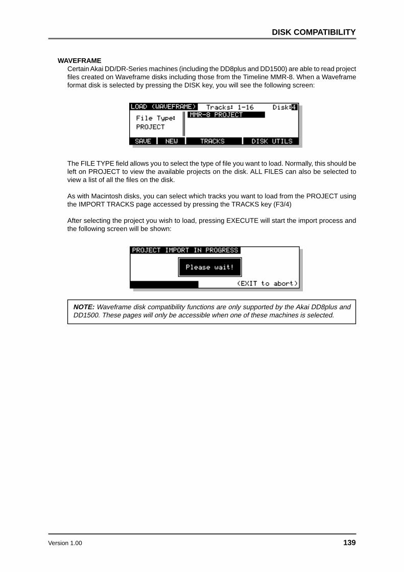
Version 1.00 139
DISK COMPATIBILITY
WAVEFRAMECertain Akai DD/DR-Series machines (including the DD8plus and DD1500) are able to read projectfiles created on Waveframe disks including those from the Timeline MMR-8. When a Waveframeformat disk is selected by pressing the DISK key, you will see the following screen:
The FILE TYPE field allows you to select the type of file you want to load. Normally, this should beleft on PROJECT to view the available projects on the disk. ALL FILES can also be selected toview a list of all the files on the disk.
As with Macintosh disks, you can select which tracks you want to load from the PROJECT usingthe IMPORT TRACKS page accessed by pressing the TRACKS key (F3/4)
After selecting the project you wish to load, pressing EXECUTE will start the import process andthe following screen will be shown:
NOTE: Waveframe disk compatibility functions are only supported by the Akai DD8plus andDD1500. These pages will only be accessible when one of these machines is selected.

140 Version 1.00
DISK COMPATIBILITY
FAIRLIGHT MFX3PLUSCertain Akai DD/DR-Series machines (including the DD8plus and DD1500) are able to read filescreated on Fairlight MFX3plus systems. The Fairlight MFX3plus supports two types of native diskformat, RBF and FLFS. Currently, the Akai system is only able to recognise RBF formatted disks.When a Fairlight RBF format disk is selected by pressing the DISK, you will see the followingscreen:
The FILE TYPE field allows you to select the type of file you want to load. The FairlightMFX3plus stores all the information necessary to play a complete project (including all audio andedit information) in a file with the suffix ‘.MT’. The Fairlight MFX3plus also allows a separate MDL(Media Description Language) file to be created which contains all the information to play theaudio in the current project. This is identified with a ‘.DL’ suffix.
The Akai system reads the MDL file rather than the Fairlight native project file, so it is necessary toensure that this file is always created before the disk is removed from the MFX3plus system.
NOTE: Fairlight disk compatibility functions are only supported by the Akai DD8plus andDD1500. These pages will only be accessible when one of these machines is selected.
MSDOS (FAT16)Certain Akai DD/DR-Series machines (including the DD8plus and DD1500) support playback ofdisks created on the Zaxcom DEVA hard disk recorder. This is a location recorder which recordsaudio to an internal hard disk and can mirror recordings to an external SCSI device such as anIomega Jaz drive. The Akai system is able to read DEVA files which have been recorded as 16-bitBroadcast Wave or Sound Designer II files by the DEVA to a FAT16 format disk. The Akai systemcan also play back 2-channel ‘Polyphonic’ files created by the DEVA (where 2 audio channels areinterleaved). It is not able to play back 4-channel polyphonic files.
When a FAT-16 format disk created by the Zaxcom DEVA is selected by pressing the DISK key,you will see the following screen:
Unlike other disk formats supported by the Akai system, the Zaxcom DEVA does not store any‘project’ file on the disk. Instead, each audio file contains its own timestamp information. PressEXECUTE to import the DEVA audio files for playback.
NOTE: MSDOS/DEVA disk compatibility functions are only supported by the Akai DD8plusand DD1500. These pages will only be accessible when one of these machines is selected.

Version 1.00 141
SYSTEM SETUP
In this section, we will have a look at the SETUP functions we skipped earlier.
SYSTEM SETUPThe SETUP pages allow you to set certain parameters that will affect either the RE32, an individualmachine or the system as a whole. These include setting sample rates, timecode types and inputs,external connections, etc. Once configured, your system settings can be saved so that you maypersonalise your operating system.
Pressing the SETUP key displays this screen:
The soft keys F1-F5 take you to the various setup menus. As there are more menus than soft keys,F6 is used as a “MORE” key to scroll through the list of menus in groups of five:
Many SETUP pages include a parameter in the top right hand corner labelled MACHINE. Thisallows you to select if parameter settings are applied to the system as a whole (MULTI) or to asingle machine (referred to as ID1, ID 2 etc..).

142 Version 1.00
SYSTEM SETUP
SETUP - MULTIWhen MULTI mode is selected, pressing the SETUP key will display the following options:
The MULTI SETUP pages are designed to allow easy configuration of parameters that should beset identically on each machine connected to the system.
Pressing RATES (F1) will take you to the SYSTEM RATES page:
This page is used to set the system’s global sample rate and frame rate.
The parameters are:
SAMPLE RATE This sets the system’s sample rate. You may select 32kHz, 44.056kHz,44.1kHz and 48kHz. Other options may be available depending on thefacilities available on the connected machines.
On entry to this page, if all connected machines are set to the samesample rate, then this rate will be displayed. If not, the sample rate fieldwill say “* DO NOT MATCH *” until a new rate is selected.
NOTE 1: This page will only allow selection of sample rates that are supported on all theconnected machines.
NOTE 2: Recordings made at a sample rate other than the selected sample rate will play backat the wrong speed. For example, if the sample rate is set to 44.1kHz and you try to play backa recording made at 48kHz, the recording will play back slow. Therefore, please make surethat your recordings are made at the correct sampling rate. Recordings made at differentsample rates cannot be used in the same project.
TC FRAME RATE This shows the system’s timecode rate.
This field is not editable, but instead serves as a visual check that allmachines are configured correctly. If all machines are set to the sameframe rate, then this rate will be displayed here. If not, this field will say“* DO NOT MATCH *”.
Timecode frame rates can be individually set on each machine asexplained later in the section on TIMECODE SETUP.

Version 1.00 143
SYSTEM SETUP
DISPLAYPressing DISP (F2) on the main MULTI SETUP page will take you to the DISPLAY page:
The parameters on this page are:
DISPLAY STYLE This allows you to set the type of timecode you wish the RE32 to display.Normally, this is the same as the timecode type selected in the EXT.TIME SOURCE field on the SYNC page (and the RE32 will take care ofthis automatically) but you may choose to view another time display ifyou wish. The selections are:
AS EXT. TIME SOURCE - The time display style is automatically selectedto be the same as the timecode selected in the EXT. TIME SOURCEfield.
23.98 fps - 23.98 frames per second (24 frames per second with a 0.1%pulldown for use when synchronising film to NTSC video).
24 fps - 24 frames per second.
25 fps - 25 frames per second.
29.97 fps - non-drop 29.97 frames per second.
29.97 fps drop - drop frame 29.97 frames per second.
30 fps - non-drop 30 frames per second.
30 fps drop - drop frame 30 frames per second.
Feet, 24fps 16mm - feet and frames at 24 frames per second asreferenced to 16 mm film.
Feet, 24fps 35mm - feet and frames at 24 frames per second asreferenced to 35mm film.
Frames, 24fps - frames only at 24 frames per second.
Frames, 25fps - frames only at 25 frames per second.
Frames, 30fps - frames only at 30 frames per second.
Frames, 29.97fps - frames only at 29.97 frames per second.
Hr:Min:Sec:mS - time will be displayed in hours, minutes, seconds andmilliseconds.
Seconds (Secs.mS) - time will be displayed in seconds and millisecondsonly.

144 Version 1.00
SYSTEM SETUP
25fps film (+4.1%) - display 25 frames per second but with a 4.1%playback speed offset for use when working with material that has beentransferred from film to video.
24fps film (-4%) - display 25 frames per second but with a 4% playbackspeed offset for use in European film applications when working withmaterial that has been transferred frame-by-frame from 24fps film to25fps video.
MIDI B/B/C - time will be displayed as bars, beats and clocks as definedby the current MIDI tempo map (see the section on TEMPO MAPS formore details).
NOTE 1: It must be said that some of the latter options are for use in very specialisedapplications. You will know if they are useful for you. The normal selection made is 24, 25,29.97 or 30fps. Those working in film or cartoons may like to use other display styles.
SUB-FRAMES This selects how many sub-frames will be displayed per frame.
Available selections are :
OFF The sub-frame display is switched off
10th Frames Normal display with 10 sub-frames per frame
Film Perfs This counts film perforations at 4 perforationsper frame.
Video Fields This counts video fields at 2 fields per frame.
LCD CONTRAST This allows the contrast of the LCD display to be changed for bettervisibility by using the DATA +/- keys.
DISPLAY OFFSETPressing OFFSET (F6) on the DISPLAY page takes you to the DISPLAY OFFSET page:
When the OFFSET field is OFF, the timecode displays will show either absolute or relative time asselected. When the OFFSET field is ON, the timecode displays will show be adjusted according tothe offset entered on this page.
FOOTAGE DISPLAYWhen footage (Feet/Frames) display styles are selected on the SYSTEM ‘DISPLAY’ page, thecurrent position is calculated using the MARK time as zero footage. Other timecode offsets areignored. This allows a project to be setup with a TIMECODE RCV OFFSET for use when theproject is loaded into a machine chasing LTC as well as a separate and unrelated footage zero.The MARK time is stored from the STORE LOCATE page.

Version 1.00 145
SYSTEM SETUP
RECORD SETUPPressing RECORD (F2) on the main MULTI SETUP page will take you to the RECORD SETUPpage that we looked at earlier in the section on recording:
The parameters are:
CROSSFADE This allows a record crossfade of 0 to 80ms to be set.
AUTO MONITOR Here you may select how you will monitor the input signal. The defaultselection is RECORD AND STOP. With this selected, you will hear theinput signal under the following conditions:
HEAR INPUT?RECORDSTOP PLAYBACK
YES NOYES
RECORD TRACK'S PLAY SELECT KEY ON
RECORDSTOP PLAYBACKYESYES
RECORD TRACK'S PLAY SELECT KEY OFF
YESHEAR INPUT?
The other selection you may make is RECORD ONLY. With this selected,you will only hear the input signal whilst actually recording, regardless ofthe status of the record track’s PLAY select key. I.e.:
RECORDSTOP PLAYBACKYESNO
RECORD TRACK'S PLAY SELECT KEY ON OR OFF
NOHEAR INPUT?
RECORD ONLY is useful when you only ever want to hear the inputsignal during record and at no other time. The system will take care ofthe switching automatically.
RECORD MODE In this field, you may select how the recordings you are about to makeare stored in the project.
The default setting is PROJECT ONLY. With this selection, newrecordings will be placed only into the currently active project. Thisselection is non-destructive - each time a new recording is made, existingfiles on disk from previous recordings will be unaffected.
You may also select DESTRUCTIVE. This is a special type of recordmode that behaves more like traditional tape.

146 Version 1.00
SYSTEM SETUP
As mentioned, recording is non-destructive by default but, sometimeswhen recording, it is possible to build up a lot of redundant audio on yourdisk, especially if you are dropping in and out over the same point timeand time again (for example, when recording vocals). As a result, yourdisk can soon become full of audio you cannot access or use. TheDESTRUCTIVE record mode goes some way to overcome this.
When DESTRUCTIVE recording mode is on, if you record over existingcues, the audio associated with the original cue may be erased fromdisk. However, you must either record over the original cue completely,or start recording from within a cue to past its end - dropping in and/orout half way through the cue will not cause the original cue’s audio to bedeleted from disk. For example:
DROP IN DROP OUT
DROP IN DROP OUT
DROP IN DROP OUT
DROP IN DROP OUT
DROP IN DROP OUT
Will not erase original
Will not erase original
Will erase the region of the original recording between the DROP IN and DROP OUT points.
Will erase original
Will erase original
New recording
New recording
New recording
New recording
New recording
If you are using AUTO-PUNCH to drop in and out of record automaticallyand you have to keep repeating the auto-punch over and over again, theDESTRUCTIVE mode will be useful as it will help prevent the build up ofunwanted recordings on your disk.
NOTE: There are certain considerations regarding destructive recording that you should beaware of.
• THERE IS NO UNDO FOR RECORDINGS WHEN DESTRUCTIVE MODE IS USED.
• After you have just loaded a new project, as a safety factor, recording over cues in thatproject will not delete their audio from disk and the original project cannot be damaged. If,however, you record over cues recorded since the project was loaded, newly recordedcues’ audio will be deleted from disk.

Version 1.00 147
SYSTEM SETUP
The destructive record mode will go some way to avoiding the build upof unnecessary audio on your disk but, given the above points, theremay be times when you will need to perform a manual cleanup orminimise.
** WARNING **
BECAUSE OF THE DESTRUCTIVE NATURE OF THIS FUNCTION, PLEASE MAKESURE IT IS NOT INADVERTENTLY SELECTED WHEN RECORDING AS YOU RUN THE
RISK OF LOSING VALUABLE DATA.
For example, if you are used to using non-destructive recording but receive a disk whereDESTRUCTIVE record mode is enabled, you may be working in your usual way, thinkingthat new recordings are recoverable when, in fact, they are being deleted from disk everytime you record over them. A good example may be where you are repeatedly dropping in
over dialogue recordings, unaware that DESTRUCTIVE mode is set. You may think that youcan retrieve ‘out-takes’ after the artist has left only to find that only the very latest recordings
you made are available on disk. In this case, before recording over existing cues, pleasecheck that DESTRUCTIVE record mode has not been selected.
** THERE IS NO UNDO WHEN DESTRUCTIVE RECORD IS USED **
PUNCH MODE This selects how the system will respond if the record track selectionsare changed while the transport is in record.
Available selections are:
NORMAL This is the default setting. The record track selectionscan not be changed while the transport is in record.
TRACK KEYS In this mode, the transport responds in the samemanner as a conventional MTR. Pressing the RECand PLAY keys will put the system into a ‘record-ready’ condition waiting for tracks to be punched infrom the track select keys. If no tracks are selectedat the time the REC and PLAY keys are pressed, theREC key will flash. In this condition, when any of thetrack select keys are pressed the system will punchinto record on the selected track(s) and the REC keywill light steadily. When a track select key is pressedagain, that track will be punched out of record.
PRIMED In this mode, recording will start immediately onselected tracks when the REC and PLAY keys arefirst pressed. After this, if new record tracks areselected, the appropriate track select key(s) will flashindicating that the track is in ‘record-ready’, butrecording will not actually start until the PLAY key ispressed again while holding down the REC key. Whilein record, pressing the track select key of a trackthat is actually recording will punch that track out ofrecord and back into the ‘record-ready’ state.

148 Version 1.00
SYSTEM SETUP
NOTE: The TRACK KEYS and PRIMED punch modes are only available on 8 track machines(e.g. DD8, DD8plus). The PUNCH MODE parameter is not shown on this screen if othermachines are being used in the system.
Press EXIT at any time to leave this page and return to the main RECORD screen.
SPEEDPressing SPEED (F4) on the main MULTI SETUP page will take you to takes you to one of twopages depending on the synchronisation status of the system:
If the ON-LINE key is switched OFF (Internal Time Source), pressing SPEED (F4) takes you tothe Varispeed menu :
The parameters on the page are:
SPEED This sets a percentage by which the current playback speed will bealtered. The range is +/- 50%.
VARISPEED This parameter enables or disables the varispeed playback function.
NOTE: It is not possible to record while VARISPEED playback is enabled.
If ON-LINE is ON (Chasing External Time Source), the SPEED key takes you to the ExternalSource Speed page:
In this page, there are no user parameters. This is used only as a Time Source analyser, in orderto check the Source format and quality (speed and stability).

Version 1.00 149
SYSTEM SETUP
TEMPO MAPSThe Akai DD/DR system allows you to create tempo maps for use when synchronising to MIDIsequencers. On the RE32, this function is accessed by pressing TEMPO (F5) on the main MULTISETUP page. You will see this screen display:
Any machine in the system can act as a master to a sequencer synced to the machine using MIDITime Code (MTC) or MIDI clock with Song Position Pointer (SPP). Of these two options, MTC isrecommended for more accurate synchronisation as this is timecode via MIDI although if yoursequencer does not have MTC, MIDI clock with SPP is a perfectly good way to synchronise yoursequencer to the system.
The principle behind a TEMPO MAP on the Akai DD/DR system is that a machine can issue tempochanges and changes in time signature to the sequencer as part of a project. Without this, anyvariation of tempo in the recorded material on disk would not be passed to the sequencer and thetwo machines would very quickly drift out of sync. By placing tempo changes and time signaturechanges at the appropriate point, the sequencer can follow the system exactly. To achieve this, ofcourse, your sequencer must be set to external sync so that the Akai DD/DR is in control of itstempo and time signature. ADDITIONALLY, THE SELECTED MACHINE MUST BE SET TOGENERATE MIDI SPP. This is done in the SINGLE MACHINE SETUP / SYNC page describedlater.
When working with MIDI sync in this way, it is recommended you use the MIDI BBC (bars/beats/clocks) time display style set in the SETUP / DISPLAY page.
NOTE: When MIDI B/B/C is selected as the TIME DISPLAY style, this will have implications onfunctions elsewhere on the RE32.
For example, if you use NUDGE, the DATA ENTRY +/- keys will nudge in beats and SHIFT ++/- keys will nudge in clocks (if you need more accurate nudge amounts, select an H/M/S timedisplay). The number of beats/bars you nudge by can be set in the NUDGE SET page.
LOCATE functions also change slightly when MIDI B/B/C is selected in that you may go to aspecific bar/beat as well as to time and/or a locate memory.
You will also note that the PLAY TO and FROM work in bars and beats (the exact amount maybe set by pressing SHIFT+PREROLL)
PRE-ROLL and CYCLE PRE-ROLL are also expressed in bars when MIDI B/B/C is selectedas the time display.
The system can store up to 10 tempo maps in memory. These are associated with any givenproject and are saved to disk with the project (typically, you will probably only ever make use ofSONG 01 as the tempo map for your project). A tempo map can have up to 200 tempo changesand up to 20 time signature changes.
Tempo maps may be named (up to 6 characters3 ) in the usual way.
3 This is to maintain compatibility with the Akai DR8 which can only use a 6 character name.

150 Version 1.00
SYSTEM SETUP
CREATING A MIDI TEMPO MAPTo create a tempo map, use SONG 01 as the starting point. You will see that there is a tempo andt.sig (time signature) entry at the start of the song. These determine the map’s starting tempo andcannot be deleted. You may edit them, however, to something more suitable simply by moving thecursor to the VALUE field and entering the tempo and time signature as appropriate.
The first thing you should do when creating a tempo map is identify the start of the song and resetthe start time so that the song starts at bar 1, beat 1, clock 1 (this may be before or after a count inas you wish). Locate to the start of the song and carefully jog over it until you have the exact startpoint. Now press RESET START in the TEMPO MAP page. You will see this prompt:
Press EXECUTE to set the song start, EXIT to cancel. All tempo changes and/or time signaturechanges you enter into the map will now be referenced to that song start point. Failure to mark thesong start correctly will mean that tempo changes and time signature changes will not appear atthe right point and so may cause sync problems with your sequencer.
After that, to build more steps into the map, first play/spool/jog/whatever to the point where youwant the first change to be and press the ADD key (F3) - this will show this prompt:
You should respond accordingly, press F5 to add a tempo change or F6 to add a time signaturechange. Pressing F5 will show this prompt:
You may abort this by pressing EXIT.
Pressing F6 will show this prompt:
Again, press EXIT to abort.
NOTE: Because time signature changes can only occur at the start of a bar, adding a t.sig stepwill place it at the nearest bar boundary.
The cursor will automatically be placed on the step you have just created and you may edit it’svalue (the default step value for tempo is 120.0 BPM and for t.sig it is 4/4 - these should be editedas appropriate).
When you add tempo changes and or time signature changes to your map, you will note that theseare shown on the ‘locate bar’ of the GRID:
A ‘T’ is shown to indicate the position of a tempo change and a ‘B’ (beat) is shown to indicate theposition of a change in time signature.
NOTE: When you are zoomed in vertically on the GRID, when you add a t.sig step, you maynot see the ‘B’ appear. This will be because the bar boundary is off the screen. When youzoom out, you will see it.
Continue adding tempo changes and new time signatures as you need through the project.

Version 1.00 151
SYSTEM SETUP
You will note that as you add steps to the tempo map, once you exceed four steps, two up anddown arrows will appear to indicate that there are steps ‘above’ and ‘below’ the screen:
Use the cursor UP/DOWN keys to scroll through your tempo map.
DELETING TEMPO MAP STEPSIf you make a mistake or wish to delete any steps in the map, move the cursor to the step you wishto erase and press F6 - DELETE. As a precaution against accidentally deleting steps, you willreceive this prompt:
Press EXECUTE to delete the selected step or EXIT to abort.
LOCATING TO STEPSYou may use LOCATE - F4 - to go directly to steps in the tempo map. Simply move the cursor tothe step you wish to locate to and press LOCATE followed by EXECUTE (EXIT to abort, of course).
Once you have constructed a tempo map, it will be automatically saved with the current project ifAUTOSAVE is enabled, or you can save it manually by saving the project using the SAVE functionin the usual way.

152 Version 1.00
SYSTEM SETUP
MORE SETUP FUNCTIONSBack on the main MULTI MACHINE SETUP page, pressing the MORE (F6) key will take you to asecond page of options:
SAVE SETTINGSPressing SAVE (F1) on the second MULTI SETUP page will take you to the SAVE SYSTEMSETTINGS page:
As the screen informs you, the system will power up according to the settings you save now. If youwish, you may also reset the system settings to the default settings contained in the operatingsystem by pressing ROM DEFAULT (F5/F6).
There are two kinds of settings stored in the system. The first are machine settings relating to thecurrent setup of each machine in the system. For example, tracks selected for playback, editingand/or record, the sample rate, external timecode selection, input routing, etc.. These settings arestored in the flash memory of each individual machine connected to the system.
The second group of settings relate to the configuration of the RE32 itself. For example, the trackzoom selection, LCD contrast and VGA display options. These settings are stored in the flashmemory of the RE32 itself.
Pressing EXECUTE will save all settings parameters in the system (including each machine’s ownsettings as well as those for the RE32). Pressing RE32 ONLY (F1/F2) will save just the localsettings relating to the RE32.
LOAD SETTINGSPressing LOAD (F2) on the second MULTI SETUP page takes you to the LOAD SYSTEMSETTINGS page:
Pressing EXECUTE will replace the current system settings with those stored in the flash ROM ofeach device, effectively returning the system to its power-up state.
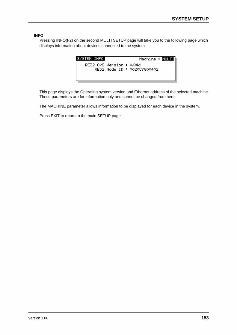
Version 1.00 153
SYSTEM SETUP
INFOPressing INFO(F2) on the second MULTI SETUP page will take you to the following page whichdisplays information about devices connected to the system:
This page displays the Operating system version and Ethernet address of the selected machine.These parameters are for information only and cannot be changed from here.
The MACHINE parameter allows information to be displayed for each device in the system.
Press EXIT to return to the main SETUP page.

154 Version 1.00
SYSTEM SETUP
SETUP - SINGLE MACHINEThe MULTI MACHINE SETUP pages allow the system to be configured quickly and easily formany applications. However, for more complex configurations, it may be necessary to setup certainparameters on individual machine. SINGLE MACHINE SETUP allows this individual parametersettings to be accessed.
When a single machine is selected on the SETUP page, the following options will be shown:
DIGITAL SETTINGSPressing DIGI (F1) on the SINGLE MACHINE SETUP page will take you to the following page:
The parameters are:
MACHINE This allows you to select which machine in the system you are configuring.
SAMPLE RATE This sets the machine’s sample rate. You may select 32kHz, 44.056kHz,44.1kHz and 48kHz. Other options may be available depending on thefacilities available on the selected machines.
NOTE : Recordings made at a sample rate other than the selected sample rate will play backat the wrong speed. For example, if the sample rate is set to 44.1kHz and you try to play backa recording made at 48kHz, the recording will play back slow. Therefore, please make surethat your recordings are made at the correct sampling rate. Recordings made at differentsample rates cannot be used in the same project.
Version 1.00 155
SYSTEM SETUP
DIGITAL SYNC This allows you to synchronise the selected machine to a variety of videoand wordclock synchronisation sources for precise systemsynchronisation. The options available (depending on the capabilities ofthe selected machine) are:
INTERNAL CLOCK This selection uses the machine’s internal crystal as its sync source andso the system is ‘free running’. This is the selection used when using themachine on its own - when using it with external video equipment, toprevent drift of audio to picture, it is recommended to sync the entiresystem (i.e. VTR, all machines, etc.) to one of the external wordclock orvideo sync sources described below.
DIGITAL INPUT This synchronises the machine to the digital wordclock signal beingreceived from the optional digital audio interface (TDIF, ADAT or AES/EBU).
On the DD1500 there are two digital input sources which are displayedas:
DIGI IN A - This synchronises the DD1500 to the digital wordclock signalbeing received through DIGITAL INPUT A. This selection is automaticallymade when recording when this input is used as the input source in theINPUTS routing matrix (see RECORDING).
DIGI IN B - This synchronises the to the digital wordclock signal beingreceived through DIGITAL INPUT B. This selection is automatically madewhen recording when this input is used as the input source in the INPUTSrouting matrix (see RECORDING).
NOTE 1: If optional DIO4 DIGITAL INPUTS are installed in the DD1500m, you will also receiveDIGI IN C. in this field. When recording using digital inputs C - F, wordclock should always bereceived through DIGI IN A.
NOTE 2: When recording through multiple digital inputs, these signals MUST ALL BE AT THESAME SAMPLING FREQUENCY .
PAL/SECAM Video This synchronises the machine to a video sync signal through the SYNCBNC connector on the rear panel. Typically, this will be used in Europeto sync to a common PAL/SECAM house sync source.
NTSC 29.97Hz Video This synchronises the machine to an NTSC 29.97Hz house sync signalthrough the SYNC BNC connector. This would normally be used in Japanor America when 29.97 frames per second timecode is being used.
NTSC 30Hz Video This synchronises the machine to an NTSC 30Hz house sync signalthrough the SYNC BNC connector. This would usually be used in Japanor America when 30 frames per second timecode is being used.
PAL/SECAM (VITC in) This option is available on the DD1500 only and synchronises themachine to a video sync signal through the VITC SYNC BNC connection.Typically, this will be used in Europe to sync to a common PAL/SECAMhouse sync source.

156 Version 1.00
SYSTEM SETUP
NTSC 29.97Hz (VITC in) This option is available on the DD1500 only and synchronises themachine to an NTSC 29.97Hz house sync signal through the VITC SYNCBNC connection. This would normally be used in Japan or America when29.97 frames per second timecode is being used.
NTSC 30Hz (VITC in) This option is available on the DD1500 only and synchronises themachine to an NTSC 30Hz house sync signal through the VITC SYNCBNC connection. This would normally be used in Japan or America when30 frames per second timecode is being used.
WORDCLOCK On the DD8 or DR16pro, this allows you to sync the machine to awordclock signal through the SYNC BNC connector.
On the DD1500, this option allows you to sync to a wordclock signalthrough the WORDCK (A) BNC connection.
This is used with a Sony PCM1630, etc. that has a separate SDIFwordclock output.
NOTE 1: If a wordclock sync source is selected and is being successfully received, the W/CRCV LED above the RE32’s timecode display will illuminate. If this LED flashes, this indicatesthat there is some kind of problem with the wordclock (i.e. it is not connected or the cable isfaulty, whatever). Please check your connections.
NOTE 2: Recordings made at a sample rate other than the rate of the external wordclocksource will play back at the wrong speed. For example, if the wordclock being received is44.1kHz and you try to play back a recording made at 48kHz, the recording will play back slow.Please make sure that you are receiving the correct wordclock rate.
AUTO DIGITAL SYNC If this field is ON, the DIGITAL SYNC automatically switches to theselected Digital input when tracks are enabled for recording.
OFF is for use with Yamaha 02R and other digital mixing desks whenthe selected machine is being used as the clock source for the desk. Inthis case, the machine should not switch to digital sync when a digitalinput from the desk is enabled, to prevent a sample-clock loop.
EMPHASIS This selects if the emphasis flag will be set on the digital outputs, andalso controls the de-emphasis filter on the DA option board.
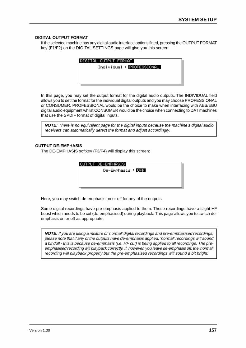
Version 1.00 157
SYSTEM SETUP
DIGITAL OUTPUT FORMATIf the selected machine has any digital audio interface options fitted, pressing the OUTPUT FORMATkey (F1/F2) on the DIGITAL SETTINGS page will give you this screen:
In this page, you may set the output format for the digital audio outputs. The INDIVIDUAL fieldallows you to set the format for the individual digital outputs and you may choose PROFESSIONALor CONSUMER. PROFESSIONAL would be the choice to make when interfacing with AES/EBUdigital audio equipment whilst CONSUMER would be the choice when connecting to DAT machinesthat use the SPDIF format of digital inputs.
NOTE: There is no equivalent page for the digital inputs because the machine’s digital audioreceivers can automatically detect the format and adjust accordingly.
OUTPUT DE-EMPHASISThe DE-EMPHASIS softkey (F3/F4) will display this screen:
Here, you may switch de-emphasis on or off for any of the outputs.
Some digital recordings have pre-emphasis applied to them. These recordings have a slight HFboost which needs to be cut (de-emphasised) during playback. This page allows you to switch de-emphasis on or off as appropriate.
NOTE: If you are using a mixture of ‘normal’ digital recordings and pre-emphasised recordings,please note that if any of the outputs have de-emphasis applied, ‘normal’ recordings will sounda bit dull - this is because de-emphasis (i.e. HF cut) is being applied to all recordings. The pre-emphasised recording will playback correctly. If, however, you leave de-emphasis off, the ‘normal’recording will playback properly but the pre-emphasised recordings will sound a bit bright.

158 Version 1.00
SYSTEM SETUP
SYNC SETTINGSPressing SYNC (F2) on the SINGLE MACHINE SETUP page will take you to the following page:
The parameters on the page are:
EXT. TIME SOURCE Here, you may choose the type of external timecode synchronisationyou are using and works in conjunction with the ON-LINE key on theRE32. When the ON-LINE key is not switched on, the system is ‘freerunning’. With the ON-LINE key switched on, the system will not playbackor record unless the timecode type selected here is received. Theselections in this field are:
SMPTE 24 fps - This selects that the selected machine will synchroniseto timecode running at 24 frames per second. This would be a typicalselection to make when synchronising to film equipment.
EBU 25 fps - This selects that the selected machine will synchronise totimecode running at 25 frames per second. This would normally beselected when sync’ing to EBU timecode in Europe.
SMPTE 29.97 nd - This selects that the selected machine will synchroniseto non-drop timecode running at 29.97 frames per second. This wouldtypically be used in America and Japan when working with NTSC colour.
SMPTE 29.97 drop - This will synchronise the selected machine to 29.97drop timecode - NTSC colour. This would normally be used in Americaor Japan.
SMPTE 30 nd - This selects that the selected machine will synchroniseto non-drop timecode running at 30 frames per second. This is thestandard for NTSC black and white television and would typically beused in America, Canada and Japan. Many American and Japanesemusic studios use this frame rate.
SMPTE 30d NTSC BW - This will synchronise the selected machine to30 drop frame timecode. This is the standard for NTSC black and whitetelevision and would occasionally be used in America, Canada or Japan.

Version 1.00 159
SYSTEM SETUP
NOTE: On many synchronisers and some pieces of video equipment, what they display as30fps drop is actually 29.97fps drop. On the Akai DD/DR machines, 30d NTSC BW is actually30 frames per second, dropping a frame every now and then and so runs a little under 1%faster than true 29.97fps drop. You should select 29.97 drop when working with NTSC colourin America, Japan or Canada. and 30 drop when working with black and white. 30d NTSC BWis unlikely to be used very often but please do not confuse Akai’s 30 drop-frame with otherequipment’s which may actually be 29.97fps drop.
VITC 25 fps - This selects that the selected machine will synchronise toVITC (Vertical Interval TimeCode) running at 25 frames per second. Thiswould normally be selected when sync’ing to EBU VITC in Europe.
VITC 29.97 nd - This selects that the selected machine will synchroniseto non-drop VITC running at 29.97 frames per second. This would typicallybe used in America and Japan when working with colour television.
VITC 29.97 drop - This will synchronise the selected machine to 29.97drop VITC. This would normally be used in America or Japan whenworking with colour television.
VITC 30 non-drop - This selects that the selected machine willsynchronise to VITC running at 30 frames per second. This would typicallybe used in America and Japan when working with NTSC black and whitetelevision.
VITC 30d NTSC BW - This will synchronise the selected machine to 30drop VITC. This would normally be used in America or Japan whenworking with NTSC black and white television (see SMPTE 30d NTSCBW).
Biphase 24fps x 2 - This selects that the selected machine will sync tobi-phase at 24 frames per second with 2 cycles per frame. This is usedwhen synchronising the DD1500 to film equipment.
Biphase 25fps x 2 - This selects that the selected machine will sync tobi-phase at 25 frames per second with 2 cycles per frame. This is usedwhen synchronising the system to film equipment.
Biphase 24fps x 4 - This selects that the selected machine will sync tobi-phase at 24 frames per second with 2 cycles per frame. This is usedwhen synchronising the system to film equipment.
Biphase 25fps x 4 - This selects that the selected machine will sync tobi-phase at 24 frames per second with 4 cycles per frame. This is usedwhen synchronising the system to film equipment.
Biphase 24fps x 10 - This selects that the selected machine will sync tobi-phase at 24 frames per second with 10 cycles per frame. This is usedwhen synchronising the system to film equipment.
Biphase 25fps x 10 - This selects that the selected machine will sync tobi-phase at 24 frames per second with 10 cycles per frame. This is usedwhen synchronising the system to film equipment.

160 Version 1.00
SYSTEM SETUP
EBU 25fps (+4%) - This special selection should be made when workingwith video material that has been derived from a frame-by-frame transferfrom 24 fps film to 25 fps video. When material is transferred in this way,the visuals will actually run 4.1% faster when played from the video. Asa result, the system needs to playback audio with the same speed offsetin order to maintain sync.
This selection should be used when working with material that has beentransferred from film in this way. Whilst working with the video, the audiowill play back slightly faster and may sound unnatural but this is not aproblem as, ultimately, the audio will be played back synced to the masterfilm at 24fps at which point, correct playback speed will be restored.
NOTE 1: It is not possible to record audio when synchronised to this selection.
NOTE 2: You must select 25fps (+4.1%) as the time display style - see below.
SMPTE/EBU+RS422 - These options are available at all frame ratesand are for use with RS422 equipped VTRs when the selected machineis acting as an RS422 master controller (i.e. when all playback, locating,jogging, etc., of both the selected machine and VTR are controlled fromthe RE32). SMPTE/EBU from the VTR is still connected as usual via theEXT. TIME input and the ON-LINE key must be switched on. The selectedmachine will receive timecode information in playback from the LTCconnection but, when working in slow motion, it receives timecode overRS422 making locking of the two machines tighter.
NOTE: The SMPTE+RS422 selection described above MUST be used when using the selectedmachine as an RS422 master.
SMPTE/EBU+VITC - These options are available on the DD1500 only(at all frame rates) and allow the DD1500 to follow SMPTE/EBU timecodeas normal during playback but, during extremely slow motion playbackor jogging, the DD1500 automatically switches to VITC for better slowmotion lock between the machines. Naturally, both the LTC and VITCinputs must be used when this timecode selection is made.
NOTE: When the DD1500 switches to VITC at very, very slow jog speeds, you will not hearaudio as you jog but you will notice improvements in the accuracy of frame locking at suchslow speeds.
RS422 - It is also possible to synchronise the selected machine totimecode over RS422 only and all frame rates are supported. However,you will note that this is primarily of use when using the system with anon-linear video recorder (see the section that explains the RS422functions for more details on this).

Version 1.00 161
SYSTEM SETUP
TIME GENERATOR Here you may select the type of timecode the selected machine willgenerate. The options are:
RE-GENERATE SMPTE - This option is available on the DD1500 onlyand will re-generate fresh, electronic SMPTE/EBU timecode at whateverrate is being received. You may find this useful for re-striping a tapewhere the source material has dropouts.
SMPTE/EBU selection - These will generate timecode at the selectedframe rate regardless of what the EXT. TIME source is.
BI-PHASE selection - All of the bi-phase selections will generate bi-phaseat its select frame rate and cycle rate regardless of what is EXT. TIMEsource is.
MTC - These selections will generate MIDI Timecode at all frame ratesthrough the rear panel MIDI OUT. This should be used whensynchronising a MIDI sequencer to the system.
MIDI SPP - This will generate MIDI Clock with Song Position Pointerthrough the MIDI OUT. This may also be used for synchronising MIDIsequencers.
NOTE: The Akai DD/DR Series machines can read one type of timecode and generate another.For example, they can receive SMPTE/EBU timecode at one rate and generate it at a differentrate. It can also receive SMPTE/EBU and generate Bi-Phase at any of the rates available (orvice versa). Likewise, a machine could be receiving SMPTE/EBU whilst simultaneouslygenerating MTC or MIDI Clock. In this way, any machine can be used as a very comprehensivetimecode converter to help you overcome many of the awkward situations one can be facedwith when receiving work done at different (or the wrong!) timecode rate.
GENERATE This selects when the system will generate the timecode selected above.The options are:
OFF - The selected machine will not generate the selected timecodeshown in the TIMECODE TYPE field. This may be useful to switchexternal equipment ‘off-line’.
ON - The selected machine is always generating the selected timecodewhen playing, recording, fast forwarding, rewinding, jogging and spooling.
VIA ON-LINE KEY - This allows you to switch timecode generation on oroff using the ON-LINE key. When this is selected, with the ON-LINE keyON, the selected machine will generate the selected timecode type andwhen ON-LINE is off, the selected machine will not generate timecode.This may be useful when the system is a slave to an external device butis also passing on timecode to other equipment. You can use the ON-LINE key to totally isolate the system so that it can be used on its own.
External Control - This allows you to switch timecode generation on oroff using the appropriate key on the front panel of the selected machine.

162 Version 1.00
SYSTEM SETUP
RECORD SETUPPressing RECORD (F3) on the SINGLE MACHINE SETUP page will take you to the followingpage:
This page is very similar to the RECORD SETUP page described earlier in the section on recordingand includes all the same parameters. Additionally, it provides direct access to the ROUTE INPUTSpage for the selected machine.
OPERATING LEVELSThe DD8 includes a software controlled adjustment for the operating levels of its A/D and D/Aconvertors. When a DD8 is selected, pressing LEVELS (F4) on the SINGLE MACHINE SETUPpage will take you to the following page:
The parameters on this page are:
MACHINE This allows you to select which machine in the system you are configuring.
REFERENCE LEVEL The Reference Level is used to set the 0 VU of the A/D and D/Aconverters.
Available selections are -12 dB , -16 dB, -18 dB and -20 dB.
If a machine that does not have support for this function is selected, you will see the followingmessage:

Version 1.00 163
SYSTEM SETUP
REMOTE PAGESPressing REMOTE (F5) on the SINGLE MACHINE SETUP page will take you to the followingpage:
This page is used to setup a variety of options relating to external control of the selected machine.The available options are shown on the soft keys and will vary depending on the interfaces fitted inthe selected machine.
The MACHINE parameter, as on other SETUP pages, allows you to select which machine in thesystem you are configuring.
Pressing the AKNET key takes you to a page which shows the Ethernet ID number assigned to theselected machine. This number is programmed during production:
Pressing the MIDI key takes you to the following page:
This allows you to setup the selected machine as a SLAVE for MIDI MACHINE CONTROL.
Pressing the RS422 key takes you to the RS422 MACHINE CONTROL setup pages described ina separate section.

164 Version 1.00
SYSTEM SETUP
GPIO SETUPSome machines may be fitted with an interface that offers several GPIs (General Purpose Inputs)and GPOs (General Purpose Outputs) that may be used for a variety of purposes. For example,the GPIs may be used for track arming control from an external mixing console with the GPOsproviding track status tallies.
If the selected machine is a DD8 or DR16pro that has this option available pressing the GPIO keyon the REMOTE page will take you to the GPIO SETUP page:
This screen allows you to configure the GPIO board in MAG or MULTITRACK modes.
The parameters on this page are:
MODE In MAG mode, the GPIs assigned for track selections are momentary(they are triggered by a pulse).
In MULTITRACK mode, the GPIs assigned for track selections are leveltriggered. (they are held at one level to select a track and at the otherlevel to deselect it).
PUNCH IN This parameter is only shown when MULTITRACK mode is selectedand is used to select how the machine will start recording.
The available options are:
REC + PLAY The machine will start recording when bothGPI ‘RECORD’ and ‘PLAY’ commands areactivated at the same time.
REC ONLY The machine will start recording when a GPI‘RECORD’ command is received on its own.
TRACK COMMANDS With this option, the machine will behave as ifit is in MAG mode, but track selections will belevel triggered. Record track commands willonly be accepted while the transport is inmotion. When the transport motion stops, allrecord track selections are cleared.

Version 1.00 165
SYSTEM SETUP
Pressing ASSIGN (F6) will take you to the GPI assignment page.
If the selected machine is a DD1500, the above parameters do not apply and pressing the GPIOkey on the REMOTE page will take you directly to the GPI assignment page:
NOTE: When the selected machine is a DD1500m, only 3 GPIs will be shown.
This screen allows you to set parameters relating to the GPIs. The parameters are:
ACTIVE You may select OFF, HIGH and LOW. When OFF, the GPI has no function.When set to HIGH, the selected function (see below) will become activewhen a +5V signal is received at the GP input. When set to LOW, theselected function will become active when a 0V signal is received.
FUNCTION Here you may assign a range of DD8 functions to the GPIs. These include:
PLAY - When a pulse is received, playback will start.
STOP - When a pulse is received, playback will stop.
FAST FORWARD - When a pulse is received, the DD will fast forward.
REWIND - When a pulse is received, the DD will rewind.
RECORD - When a pulse is received, the DD will start recording.
PLAY TO - When a pulse is received, the DD will play to the currentNOW time.
PLAY OVER - When a pulse is received, the DD will play over the currentNOW time.
PLAY FROM - When a pulse is received, the DD will play from the currentNOW time.
PLAY IN TO OUT - When a pulse is received, the DD will play from theselected IN point to the selected OUT point.
PLAY LAST - When a pulse is received, the DD will play the last thingplayed.
PLAY BACKWARDS - When a pulse is received, the DD will play inreverse.
GRAB IN MARK - When a pulse is received, it will mark an IN point.
GRAB SYNC MARK - When a pulse is received, it will mark a SYNCpoint.
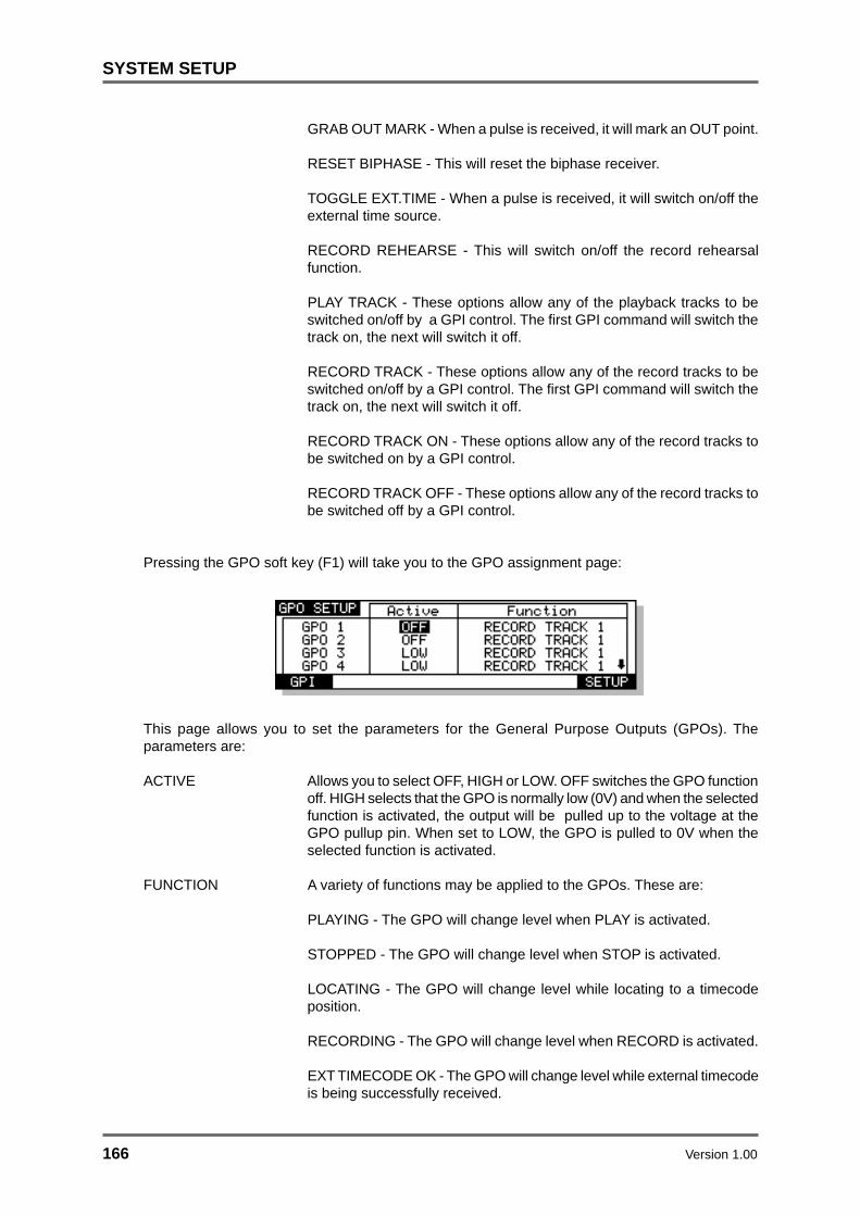
166 Version 1.00
SYSTEM SETUP
GRAB OUT MARK - When a pulse is received, it will mark an OUT point.
RESET BIPHASE - This will reset the biphase receiver.
TOGGLE EXT.TIME - When a pulse is received, it will switch on/off theexternal time source.
RECORD REHEARSE - This will switch on/off the record rehearsalfunction.
PLAY TRACK - These options allow any of the playback tracks to beswitched on/off by a GPI control. The first GPI command will switch thetrack on, the next will switch it off.
RECORD TRACK - These options allow any of the record tracks to beswitched on/off by a GPI control. The first GPI command will switch thetrack on, the next will switch it off.
RECORD TRACK ON - These options allow any of the record tracks tobe switched on by a GPI control.
RECORD TRACK OFF - These options allow any of the record tracks tobe switched off by a GPI control.
Pressing the GPO soft key (F1) will take you to the GPO assignment page:
This page allows you to set the parameters for the General Purpose Outputs (GPOs). Theparameters are:
ACTIVE Allows you to select OFF, HIGH or LOW. OFF switches the GPO functionoff. HIGH selects that the GPO is normally low (0V) and when the selectedfunction is activated, the output will be pulled up to the voltage at theGPO pullup pin. When set to LOW, the GPO is pulled to 0V when theselected function is activated.
FUNCTION A variety of functions may be applied to the GPOs. These are:
PLAYING - The GPO will change level when PLAY is activated.
STOPPED - The GPO will change level when STOP is activated.
LOCATING - The GPO will change level while locating to a timecodeposition.
RECORDING - The GPO will change level when RECORD is activated.
EXT TIMECODE OK - The GPO will change level while external timecodeis being successfully received.

Version 1.00 167
SYSTEM SETUP
EXT WORDCLOCK OK - The GPO will change level while externalwordclock is being successfully received.
EXT TIME LOCK - The GPO will indicate when the transport issuccessfully locked to external timecode.
REC TRACK - These options allow a tally to be sent when any of therecord tracks are switched on/off.
REHEARSE - These options allow a tally to be sent when rehearsemode is enabled.
TRACK SLIP 1 ..8 - These options allow an appropriate tally to begenerated when a track is slipped.

168 Version 1.00
SYSTEM SETUP
USER KEYSUSER KEYS allows the function of key presses on the RE32 to be redefined. The alternate keydefinitions are active while the USER KEY is switched on. In multi-machine setups, USER KEYSalso allows commands to be send to the currently selected machine, all connected machines orany single machine. The alternate key definitions are active while the USER KEY is switched on.
Pressing SHIFT+USERKEYS now displays this screen:
In the default state, no USER KEYS are defined. To define a key, press NEW KEY. You will see thisprompt:
Press Required keys(s) or press EXIT..
Press the key you wish to redefine. This can either be a single key, or a combination of SHIFT plusanother key. The names of the key(s) you select will be displayed in the list on the left hand side ofthe screen. On the right hand side of the screen, you can select the function you wish to assign tothis key press.
The options available include:
STORE IN Mark IN time
STORE OUT Mark OUT time
STORE SYNC Mark SYNC time
EXT.TIME Switch EXT.TIME on/off
REHEARSE Switch REHEARSE on/off
AUTO-PUNCH Switch AUTO-PUNCH on/off
ALL REC TRKS Enable all record tracks
CLR REC TRKS Disable all record tracks
REC TRACK 1 Switch selected record track on/off :REC TRACK n
EDIT TRACK 1 Switch selected edit track on/off :EDIT TRACK n
ALL PLAY TRKS Enable all play tracks
CLR PLAY TRKS Disable all play tracks

Version 1.00 169
SYSTEM SETUP
PLAY TRACK 1 Switch selected playback track on/off:
PLAY TRACK n
REWIND Rewind transport
FAST FORWARD Fast Forward transport
STOP Stop transport
PLAY Put transport into play
RECORD Send record command when PLAY is also pressed
PLAY REVERSE Play backwards
BPH RCV RESYNC Resync biphase receiver
BPH GEN RESYNC Resync biphase generator
COPY EDIT Select copy edit page
CUT EDIT Select cut edit page
ERASE EDIT Select erase edit page.
PASTE EDIT Select paste edit page
INSERT EDIT Select insert edit page
SELECT MACHINE Select machine
REC (PUNCH-IN) Drop into record
REC (TOGGLE) Drop in/out of record
The MACHINE field in the right hand column selects which machine the command will besent to when USER KEYS are enabled. The options are:
MULTI Send command to all connected machines
1 .. 16 Send command to specified machine only.
To remove a USER KEY definition, move the cursor over the item you wish to remove andpress the DELETE KEY soft key.

170 Version 1.00
SYSTEM SETUP
RC15 CONNECTIONThe RC15 is a small remote which connects to the EXPANSION port on the RE32. It has 8functions keys, 6 transport keys and a jog/shuttle wheel which can be programmed in a similarway to the USER KEYS function described previously.
It may seem bizarre to offer a remote for a remote but the RC15 can be a useful addition to theRE32 in project studios where recording and track laying is a one-man operation. The RC15can be used in, say, a vocal booth or separate, isolated studio area or could be convenientlylocated by your keyboard and/or sequencer for punching in and out of recordings and overdubsaway from the RE32. Its eight function keys are completely programmable to do whatever youwant and can be set using the RC15 SETUP page.
When the RC15 is connected, an extra softkey will appear on the USER KEYS SETUP pageaccessed by pressing SHIFT+USER KEYS.
Pressing the RC15 SETUP softkey will take you to the following screen:
The RC15 keys are listed in the column on the left hand side of the screen. The 8 function keysare listed as F1-F8, and the transport keys are listed as TRANSPORT 1-TRANSPORT 6. As onthe USER KEY SETUP page, you can select a function for each key and also select if thecommand is sent to all machines or any specific machine.

Version 1.00 171
SYNCHRONISATION
SYNCING TO EXTERNAL TIMECODEThere is nothing very special to do for this. Assuming a suitable timecode source is connectedto the first machine in the system (e.g. SMPTE etc.), select the type of timecode you wish tosync to in the SYNC page using the EXT. TIME SOURCE field and switch the ON-LINE key on.With the ON-LINE key switched on, when you press PLAY on the RE32, nothing will happenuntil the system receives timecode from the external source.
When external timecode is being received successfully, the system will play synchronised tothat timecode and the EXT T/C RCV LED above the RE32’s timecode display will be steadily lit.If at any time, the EXT T/C RCV LED flickers, this indicates a problem with the external timecodesuch as dropout. The system will ‘flywheel’ for a short while in the event of timecode dropoutbut, if the dropout is too long, the system will stop playing.
NOTE: When you switch on the ON-LINE key, PLAY is also engaged so that the system willautomatically play whenever timecode is received and will stop when external timecode isstopped. However, if you specifically press the STOP key to stop playback, you will need topress PLAY again for it to follow external timecode.

172 Version 1.00
SYNCHRONISATION
SETTING TIMECODE OFFSETSPressing OFFSETS (F5/F6) on the SYNC page will take you to the following page:
Sometimes, it is necessary to set an offset between the system and an external machine. Forexample, your project may start at 00:00:00:00 but your timecode source start at 10:00:00:00.Using this page, you may set offsets so that the two machines play in sync without you havingto extensively modify the project’s start time.
The parameters on this page are:
RECEIVER When the RECEIVER field is set to ON, the offset will be added to/subtracted from the incoming timecode so that the selected machineand external time are locked at the current absolute/relative time posi-tion.
When the RECEIVER field is set to OFF, the offset will not be added to/subtracted from the incoming timecode.
GENERATOR When the GENERATOR field is set to ON, the offset will be added to/subtracted from the output timecode.
When the GENERATOR field is set to OFF, no offset will be applied tothe timecode output.
If the project starts at 00:00:00:00.0 but the incoming timecode starts at 1 hour, you should seta TIMECODE RECEIVE OFFSET of -01:00:00:00.0. This will subtract 1 hour from the incom-ing timecode, thereby effectively providing the system with timecode starting at 00:00:00:00.0.Conversely, if the project starts at, say, 10 hours but the incoming timecode starts at 1 hour, youwould need to set +09:00:00:00.0 in the RECEIVER field, adding 9 hours to the incomingtimecode so that it plays from 10 hours.

Version 1.00 173
SYNCHRONISATION
ADVANCED OFFSETSSometimes, it is necessary to set an offset between the Akai system and an external tape orVTR machine. For example, your project may start at 00:00:00:00 but the visuals start at10:00:00:00.
Before we look at these functions, it must be said that some of the offset facilities provided onthe RE32 are a bit specialised and apply only to certain applications. If you need these specialisedfunctions, you will know what you want. However, if all you need to do is set an offset againstincoming timecode, you can ignore much of this!
The main page of the RE32 (when the ALL SAFE key is switched on) includes several keysrelating to timecode offsets:
Pressing the OFFSET key (F5/F6) gives this screen:
Here, you may set offsets so that the machines in the system play in sync with external deviceswithout you having to extensively modify the project’s start time. You may also set offsets forthe timecode displays on the RE32 and external monitor as well as setting absolute and rela-tive times.
The fields on this page are:
ZERO IS AT This sets a relative offset and allows the 00:00:00:00.0 referencetime to be placed at a time other than absolute zero. For example:
0 23.59
0
8
16 15.59
ZERO IS AT : + 08:00:00:00.0
ABS(solute)
REL(ative)
An Akai project can be likened to a 24 hour reel of tape and, usingthe REL(ative) setting, you can play across ‘midnight’.
The soft keys ABS/REL (F1/F2) on the main PLAY page switch be-tween absolute and relative time display.
ZERO (F3/F4) sets the current time as the ZERO point. This alsohas the effect of automatically switching ZERO IS AT (i.e. the REL)time display to ON. You may select ABS(olute) or REL(ative) moreconveniently using the soft keys F1 or F2 (ABS or REL) if you wish.You will note that as you switch the ZERO IS AT field on or off theABS/REL keys highlight to indicate selection.

174 Version 1.00
SYNCHRONISATION
NOTE 1: You may find it useful when starting a project from scratch to always start at, say,1 hour and use the relative time display so that the project effectively still starts at zero. Inthis way, if you suddenly find you need to add cues before 00:00:00:00, you can. If you useabsolute and start at zero, you will first have to slip all cues in the project forward to accom-modate the new cues.
DISPLAY This offset is added to relative time before it is displayed. The optionsare OFF, ON, LED ONLY.
OFF and ON should be fairly self-explanatory. LED ONLY appliesthe offset to the LED timecode display on the RE32’s panel only - thetimecode display on the external monitor does not show this offset.This is a special requirement for in situations where film and SMPTE/EBU equipment is being used together. In this case SMPTE/EBUtimecode can be displayed on the RE32’s LED timecode display andzero-based feet/frames display can be displayed on the VGA monitor’stimecode display (for example, the first frame of the film is at a SMPTE/EBU time of 10 hours but, as no film footage has elapsed, the feet/frames display on the external monitor shows 0000 feet/00 frames).
T/C RCV This is an abbreviation of TIMECODE RECEIVE OFFSET and setsan offset that is applied to incoming timecode.
T/C GEN This is an abbreviation of TIMECODE GENERATE OFFSET. Thisoffset is applied to generated timecode.

Version 1.00 175
RS422
RS422 MASTER CONTROLAny of the Akai DD/DR series machines can be used as an RS422 master using the Sony™ P2protocol. This means that all play, jog, shuttle and locate commands are issued from the Akaimachine allowing you to control a VTR equipped with RS422. Connections should be made asshown in the RS422 section of each machine’s manual.
Switching on the ON-LINE key engages the RS422 function. Because it is necessary for theexternal VTR to ‘report back’ its timecode position to the system via the SMPTE IN and EXT.TIME key, when you switch the ON-LINE key on, the EXT. TIME source is automatically en-abled to ensure correct lock up of both the Akai machine and the VTR.
However, because of the frame accuracy limit imposed on the Akai machine by the VTR overRS422, it is sometimes necessary to ‘isolate’ the Akai system for greater editing accuracy, Todo this, simply switch off the ON-LINE key - this will allow the system to be used ‘stand alone’.
As a practical example, let’s say you are trying to sync a door slam sound effect in the system’sproject with the picture on video. You could, of course, do everything referenced to frameaccurate picture but, you just cannot get the door slam precisely in sync. By switching off theON-LINE key, you can momentarily disengage the VTR, ‘isolating’ the system and you canplace the sound effect, nudging it backwards or forwards in sub-frame increments on the RE32until you think it’s at the right position. You can then re-engage the VTR by switching on the ON-LINE key again and trying it out against picture. You can repeat this process until it’s perfectlyin sync.
The RS422 SETUPparameters are accessed from the SETUP page’s REMOTE menu:
Pressing the RS422 soft key on this page will take you to the following page:
RS422 MASTER is selected in the RS422 MODE field. You will see this screen:
RS422 MACHINE CONTROL SETUPRS422 MACHINE CONTROL SETUP
LAYBACK RS422 RECORDRS422 RECORD DEVICE SETUPDEVICE SETUP
Edit delay : 2 framesEdit delay : 2 framesVTR locate offset : VTR locate offset : ()():()():()5:()().()()
RS422 Mode : RS422 Mode : MASTER
The parameters are:
EDIT DELAY This sets the delay between the edit instruction being issued and themachine responding to that command. Every machine is different(for example, a U-Matic is 6 frames and a Betacam is 2 or 3 frames -you should consult your VTR’s or edit controller’s operator’s manualfor information on this).
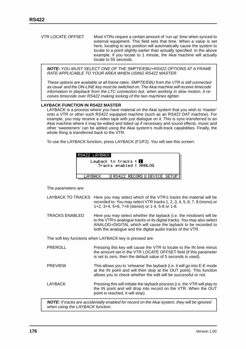
176 Version 1.00
RS422
VTR LOCATE OFFSET Most VTRs require a certain amount of ‘run up’ time when synced toexternal equipment. This field sets that time. When a value is sethere, locating to any position will automatically cause the system tolocate to a point slightly earlier than actually specified. In the aboveexample, if you locate to 1 minute, the Akai machine will actuallylocate to 55 seconds.
NOTE: YOU MUST SELECT ONE OF THE SMPTE/EBU+RS422 OPTIONS AT A FRAMERATE APPLICABLE TO YOUR AREA WHEN USING RS422 MASTER.
These options are available at all frame rates. SMPTE/EBU from the VTR is still connectedas usual and the ON-LINE key must be switched on. The Akai machine will receive timecodeinformation in playback from the LTC connection but, when working in slow motion, it re-ceives timecode over RS422 making locking of the two machines tighter.
LAYBACK FUNCTION IN RS422 MASTERLAYBACK is a process where you have material on the Akai system that you wish to ‘master’onto a VTR or other such RS422 equipped machine (such as an RS422 DAT machine). Forexample, you may receive a video tape with just dialogue on it. This is sync-transferred to anAkai machine where it may be edited and tidied up if necessary and sound effects, music andother ‘sweeteners’ can be added using the Akai system’s multi-track capabilities. Finally, thewhole thing is transferred back to the VTR.
To use the LAYBACK function, press LAYBACK (F1/F2). You will see this screen:
The parameters are:
LAYBACK TO TRACKS Here you may select which of the VTR’s tracks the material will berecorded to. You may select VTR tracks 1, 2, 3, 4, 5, 6, 7, 8 (mono) or1+2, 3+4, 5+6, 7+8 (stereo) or 1-4, 5-8 or 1-8.
TRACKS ENABLED Here you may select whether the layback (i.e. the mixdown) will beto the VTR’s analogue tracks or its digital tracks. You may also selectANALOG+DIGITAL which will cause the layback to be recorded toboth the analogue and the digital audio tracks of the VTR.
The soft key functions when LAYBACK key is pressed are:
PREROLL Pressing this key will cause the VTR to locate to the IN time minusthe amount set in the VTR LOCATE OFFSET field (if this parameteris set to zero, then the default value of 5 seconds is used).
PREVIEW This allows you to ‘rehearse’ the layback (i.e. it will go into E-E modeat the IN point and will then stop at the OUT point). This functionallows you to check whether the edit will be successful or not.
LAYBACK Pressing this will initiate the layback process (i.e. the VTR will play tothe IN point and will drop into record on the VTR. When the OUTpoint is reached, it will stop).
NOTE: If tracks are accidentally enabled for record on the Akai system, they will be ignoredwhen using the LAYBACK function.

Version 1.00 177
RS422
USING THE LAYBACK FUNCTIONThe RE32’s IN and OUT markers set the record in/out points for the VTR. Assuming the functionsdescribed above are set as appropriate, you must first press PREROLL4 . You then press LAYBACKand the VTR will drop in/out of record at the IN/OUT points marked.
You may ‘build’ the final transfer in sections (in this way, you can obtain the optimum mix section-by-section) and set IN/OUT points as appropriate. You may rehearse the drop in/out using PRE-VIEW and, when you’re happy with the results, press LAYBACK to actually ‘commit’ the recording(in both instances, you must use PREROLL to locate to a time a bit before the IN point).
It may be that you want to transfer the whole project back to the video tape in one go. In this case,set the IN at the start of the project and the OUT at the end of the project and press LAYBACK (F1/F2) to transfer the whole project back to the master video tape in one pass.
Another use of this may be to receive a video tape as described above but the ‘sweetened’version on the Akai system may be laid back to an RS422 equipped DAT machine thus preserv-ing the dialogue on the original video with a synchronised ‘master’ on DAT.
4 The layback function will not work if the machine(s) are not located to a point beforethe IN time. The layback function requires that there be some form of pre-roll.

178 Version 1.00
RS422
RS422 MASTER CONTROL OF NON-LINEAR VIDEO RECORDERSUsing the ‘RS422 only’ external timecode selection, it is possible to take full advantage of non-linear hard disk video recorders such as the FED V-MOD 100.
When using any of the SMPTE+RS422 external timecode options, although locate/lock times inthis case are virtually immediate, when jogging at slow speeds, there is no significant performanceimprovement over a VTR and the non-linear video recorder will ‘stutter’ frame by frame much likea normal VTR. However, using the ‘RS422 only’ selection, slow speed jogging is exceptionallysmooth and very tightly locked to the Akai system’s audio jogging and so is ideal for spotting audioto picture.
However, please note that because of inaccuracies in the timecode sent via RS422, when playingat nominal speed, there may be instances where there is a ±1 frame offset. This can be overcomeby switching to SMPTE+RS422 for playback and using RS422 only for jogging and spotting. Ofcourse, in the RS422 SETUP page, RS422 MODE must be set to MASTER and the ON-LINE keymust be switched to ON.

Version 1.00 179
SPECIFICATIONS
RE32 SPECIFICATIONS
Power Requirements : 120V AC 60 Hz 19 W 220 - 240V AC 50Hz
Operating Temperature : 5°C ~ 40°C
Operating Humidity : 30% ~ 80% (without condensation)
Dimensions : 483 x 86 x 310 (330 maximum) (W x H x D, mm) EIA 7U
Weight : 5.6kg
Display : 248 x 60 dot graphic LCD
Edit Resolution : Sub-frame
Connectors
Display Output : 15-pin D-sub male, Analogue level VGA (640 x 480) IBM PCFormat
Expansion Port : 9-pin D-sub male, for RC15 (optional) connection
AKAINET : BNC 50-ohms, for Ethernet (10 Base-2) connection
Keyboard Input : 6-pin mini-DIN female, for PS/2 Keyboard connection
Accessories : AKAINET Cable (BNC 50-ohms, 20m) x 1 AC Cord x 1 Operator’s Manual x 1
❈ Above specifications are subject to change without prior notice.

180 Version 1.00
INDEX
AUTO DIGITAL SYNC 156AUTO PUNCH-IN/OUT 46Auto-monitor 43, 145AUTO-PUNCH key 46AUTOLOCATOR 57Automated Punch In/Out 59AUTOSAVE 99
BBackup 114Backup Restore 121Basic Editing Concepts 24BASIC RECORDING 3516-bit audio files 4220-bit (packed) audio files 4220-bit audio files 4224-bit audio files 42
AADVANCED RECORDING 37AIFF 41AKAI audio files 41AKAI Project 104, 138AKAI->FAIRLIGHT 41AKAI->FAIRLIGHT audio files 41AKAINET 6, 9AKAINET Termination 6, 7, 9AKNET ID number 163ALL SAFE 35BIT LENGTH 42
CChoosing a Monitor Screen 6Cleanup Disk 133Clearing locate markers 58CLIPBOARD DISPLAY 13, 33Copy (Disks/Files) 107Copy (Multi-machine) 64Copy (Single Machine) 72Crossfade 43, 145Crossfade Tools 95CUE 3, 24Cue Information 31Cue Name Display 14CURSOR KEYS 15Curve (Edit Q) 92Cut (Multi-machine) 69Cut (Single Machine) 74Cut Forwards (Single Machine) 75CYCLE 59
DDAT Archive 129DAT Restore 132DATA ENTRY KEYS 18DATA ENTRY/NUDGE KEYS 18DD8 Machine ID assignment 8De-emphasis 157Delete (Files) 111Destructive record mode 37, 38, 39, 146Digital Output Fotmat 157Digital recording 52Digital Settings page 154
DIGITAL SYNC 155Discard (Multi-machine) 68Discard (Single Machine) 77Disk Compatibility 136Disk Directory 106DISK INFO 105
D (cont)DISK LABEL 29, 105DISK UTILITIES pages 105DISPLAY 6Display Connection 6DISPLAY STYLE 143DR16pro Machine ID assignment 8
EEdit Auto Zoom 32EDIT CLIPBOARD 17, 71, 72, 74, 76, 78, 80, 82Edit Cue/Q 91EDIT KEY 61EDIT PLAY KEYS 90EDIT REGION 3, 24EDITING 61EMPHASIS 157Erase (Multi-machine) 69Erase (Single Machine) 76Error Messages 34EXECUTE 18, 61EXECUTE - Completing Names 18EXIT 18EXIT - Abandoning Naming 18EXPANSION CONNECTION 6EXT T/C RCV LED 174EXTERNAL TIMECODE 174, 175
FFade (Edit Q) 88Fade Down (Edit Q) 88Fade Up (Edit Q) 88Fairlight 41Fairlight Compatibility 139FAST FORWARD 53FAT 16 140FILE TYPE 41Formatting (Backup) 114FORMATTING DISKS 28FREE ON DISK 40
GGetting around the GRID 21GPIO Setup 164GRAB function 21Grabbing Times 58GRaphic Interface Display 13GRID 3, 13Group Store/Recall 56
IIN KEY 61IN TIME 3, 61IN to OUT length 61IN->NOW 88Info page 153

Version 1.00 181
INDEX
INPUT MON 55Input Routing 47INPUT ROUTING - DR16pro 48Insert (Multi-machine) 66Insert (Single Machine) 80Invalid Edit Region 61
JJOG WHEEL 11, 19, 22JOG/SPOOL key 22JOG/SPOOL SET 22
KKEYBOARD 6
LLABEL field 105LAYBACK 176LCD 10LCD CONTRAST 144Level (Edit Q) 92LIBRARY 4Load (Project) 102Load (Settings) 152LOCATE 55LOCATE FUNCTION 21
MMac Compatibility 136Machine Box 33Machine ID assignments 8MAINS INPUT 6MARK POINT 3Meter Source 32Meters Setup 32MIDI Setup 167MIDI Tempo maps 150Minimise Disk 134Monitor Screen 6Move Region (Single Machine) 83MS-DOS Compatibility 140MULTI-MACHINE EDIT 64MULTI-MODE 4MUTING TRACKS 55
NNAMING FILES 19New Project 104NEXT Q Key 21Non-Linear Video 178NOW TIME 3, 12, 33NOW TO END 93Nudge 84NUMERIC KEYPAD 17
OOFFSET 144, 172, 173OMF 136On-Line Key 175, 178Operating Levels 162OUT KEY 61OUT TIME 3, 61Overlay (Multi-machine) 67Overlay (Single Machine) 82
PPANEL LAYOUT 10Paste (Multi-machine) 66Paste (Single Machine) 79PC Keyboard 19Peak Hold 32PLAY FROM 54, 90PLAY IN>OUT 54, 90PLAY KEY 53PLAY TO 53, 90Power up screens 9
P (cont)PRE-ROLL 59, 60PREV Q Key 21PROJECT 3PROJECT NAME 12PROMPTS 20ProTools Compatibility 136ProTools Import 137Protools Session 104ProTools Sessions (creating...) 138Punch In/Out Automation 59PUNCH MODE 147Punch modes 44
RRC15 Setup 170REC Key 53RECORD 35RECORD DISK 40RECORD MODE 37, 43, 145RECORD SETUP 43, 145, 162RECORD TYPE 41Recording digitally 52RECORDING NAME 37REDO 61REFERENCE LEVEL 162REHEARSE 46Remote Settings 163RENAMING FILES 20, 112Restoring a backup 121REVERSE PLAY 53REWIND 53Routing Inputs 47RS422 CONTROL (Layback) 176RS422 CONTROL (Master) 175RS422 Setup 163, 175Ruler 33
SS-VGA Monitor 6SAMPLE RATE 142, 154Save (Project) 98Save (Settings) 152SCROLL BAR Display 58Scroll Direction 33Scroll View Keys 16SD-II 40SD-II audio files 40SELECT CUE/EDIT CUE 91SELECT Q 24SELECT Q KEY 62

182 Version 1.00
INDEX
SET FUNCTIONS 19Setting Up 26Setup (GPIO) 164Setup (MIDI) 163Setup (Multi Machine) 142Setup (Record) 162Setup (RS422) 163Setup (Single Machine) 154SHIFT 19SHIFT key 10SHIFT+JOG 22SIGNAL GND 6SINGLE MACHINE SETUP 154SINGLE-MACHINE EDIT 70SINGLE-MODE 4SOFT KEYS 10, 18SOLOING A TRACK 55Sound Designer II 41
S (cont)Speed page 148Split (Multi-machine) 69Split (Single Machine) 86START TO NOW 93Stereo Cue 63STOP KEY 53STORE 57, 58STORE LOCATE 55STORE NEXT 58SYNC KEY 61SYNC POINT 3, 61Sync Settings page 158SYSTEM SETUP 26, 141SYSTEM STATUS 12
TTC FRAME RATE 141Tempo Maps 149TERMINOLOGY 3TIME GENERATOR 161TIMECODE DISPLAY 10Timecode Offsets 172, 173TRACK METERS 12TRACK MODE KEYS 10TRACK SELECT KEYS 10TRACK STATUS 12TRACK ZOOM KEYS 16TRACKS KEY 10TRANSPORT KEYS 10, 21, 53
UUNDO 19UNDO KEY 61USER KEYS 169UTILITIES KEYS 10
VVARISPEED 148Verifying a Backup 120VGA MONITOR LAYOUT 12VGA SETUP 31
WWaveform Magnification 16Waveframe Compatibility 139Write Protect 100WRITE PROTECTED Prompt 30
XXFADE key 96
ZZoom in/out 16


![Multitrack Power Factor Correction Architectureminjie/files/multitrackpfc_slides.pdfMultilevel Boost Converter," IEEE Transactions on Power Electronics, 2015. • [Stanford TPEL18]](https://static.fdocuments.net/doc/165x107/606d4695b75a011d7207f915/multitrack-power-factor-correction-architecture-minjiefilesmultitrackpfcslidespdf.jpg)