MULTISTREAM REALTIME CONTROL OF A DISTRIBUTED TELEROBOTIC...
165
MULTISTREAM REALTIME CONTROL OF A DISTRIBUTED TELEROBOTIC SYSTEM ASIF IQBAL SYSTEMS ENGINEERING JUNE, 2003
Transcript of MULTISTREAM REALTIME CONTROL OF A DISTRIBUTED TELEROBOTIC...
MULTISTREAM REALTIME CONTROL OF
A DISTRIBUTED TELEROBOTIC SYSTEM
ASIF IQBAL
SYSTEMS ENGINEERING
JUNE, 2003
KING FAHD UNIVERSITY OF PETROLEUM AND MINERALS
DHAHRAN 31261, SAUDI ARABIA
DEANSHIP OF GRADUATE STUDIES
This thesis, written by ASIF IQBAL under the direction of his Thesis Advisor
and approved by his Thesis Committee, has been presented to and accepted by the
Dean of Graduate Studies, in partial fulfillment of the requirements for the degree
of MASTER OF SCIENCE IN SYSTEMS ENGINEERING.
Thesis Committee
Dr. ONUR TOKER (Chairman)
Dr. MAYEZ AL−MOUHAMED (Co−Chairman)
Dr. FOUAD M. AL−SUNNI (Member)
Department Chairman
Dean of Graduate Studies
Date

To my dear parents
whose prayers, guidance and encouragement led me to the
accomplishment of this work.
Acknowledgements
All praise is due to Allah(SWT), the Most Gracious, the Most Merciful. May peace
and blessings be upon Prophet Muhammed(SAW), his family and his companions. I
thank almighty Allah(SWT) for giving me the knowledge and patience to complete
this work.
I would like to acknowledge the support and facilities provided by the Systems
Engineering and Computer Engineering departments, KFUPM for the completion
of this work.
I would like to express my profound gratitude and appreciation to my advisor Dr.
Onur Toker and my co-advisor Dr. Mayez M. Al-Mouhamed, for their consistent
help, guidance and attention that they devoted throughout the course of this work.
Their valuable suggestions and useful discussions made this work interesting for
me. Thanks are also due to my thesis committee member Dr. Fouad M. Al-Sunni
for his interest, cooperation, and constructive advice. I would like to thank Dr.
Muhammad Shafiq for his valuable advice and encouragement for this work.
Thanks are due to my friends Naveed, Ameen, Noman, Farooq, Arshad, Saad, Moeen
and to all S.E graduate students, for their moral support, good wishes and the
memorable days shared together.
Special thanks are to my parents Mr. & Mrs. Rana Bashir Ahmed Khan for their
love, sacrifices and prayers.
i

Contents
List of Figures vi
Abstract (English) x
Abstract (Arabic) xi
1 Introduction 1
1.1 Thesis Objectives . . . . . . . . . . . . . . . . . . . . . . . . . . . . . 6
1.1.1 Telerobotics . . . . . . . . . . . . . . . . . . . . . . . . . . . . 7
1.1.2 Computer Vision . . . . . . . . . . . . . . . . . . . . . . . . . 8
1.2 Organization of the Work . . . . . . . . . . . . . . . . . . . . . . . . 8
2 Literature Review 10
2.1 Network Telerobotics . . . . . . . . . . . . . . . . . . . . . . . . . . . 10
2.1.1 Supervisory Control in Telerobotics . . . . . . . . . . . . . . . 18
2.2 Stereo Vision and Augmented Reality . . . . . . . . . . . . . . . . . . 22
ii
2.2.1 Stereo Vision . . . . . . . . . . . . . . . . . . . . . . . . . . . 22
2.2.2 Augmented Reality . . . . . . . . . . . . . . . . . . . . . . . . 27
2.2.3 Classification of visualization systems based on used equipment 31
2.2.4 Classification of visualization systems based on delay and band-
width . . . . . . . . . . . . . . . . . . . . . . . . . . . . . . . 34
3 The Client-Server Framework for Stereo Image Acquisition 39
3.1 Functional Details . . . . . . . . . . . . . . . . . . . . . . . . . . . . . 41
3.1.1 Server Side . . . . . . . . . . . . . . . . . . . . . . . . . . . . 41
3.1.2 Client Side . . . . . . . . . . . . . . . . . . . . . . . . . . . . . 43
3.2 Implementation . . . . . . . . . . . . . . . . . . . . . . . . . . . . . . 44
3.2.1 Single Buffer, Serialized Transfer . . . . . . . . . . . . . . . . 45
3.2.2 Double Buffer, De-Serialized Transfer . . . . . . . . . . . . . . 47
3.3 3D Visualization . . . . . . . . . . . . . . . . . . . . . . . . . . . . . 50
3.3.1 Sync-Doubling . . . . . . . . . . . . . . . . . . . . . . . . . . . 51
3.3.2 Page Flipping . . . . . . . . . . . . . . . . . . . . . . . . . . . 51
3.3.3 Output Devices for 3D Visualization . . . . . . . . . . . . . . 53
3.4 Performance Evaluation . . . . . . . . . . . . . . . . . . . . . . . . . 53
3.4.1 Copying from SampleGrabber to DRAM . . . . . . . . . . . . 54
3.4.2 Transferring over the LAN . . . . . . . . . . . . . . . . . . . . 60
4 A Multi-threaded Distributed Telerobotic Framework 64
iii
4.1 An Overview of the Distributed Object Technologies . . . . . . . . . 66
4.1.1 CORBA . . . . . . . . . . . . . . . . . . . . . . . . . . . . . . 66
4.1.2 .NET . . . . . . . . . . . . . . . . . . . . . . . . . . . . . . . . 67
4.1.3 JAVA/RMI . . . . . . . . . . . . . . . . . . . . . . . . . . . . 68
4.2 Motivation for Using .NET Framework . . . . . . . . . . . . . . . . . 68
4.3 Server Side Components . . . . . . . . . . . . . . . . . . . . . . . . . 70
4.3.1 PUMA Component . . . . . . . . . . . . . . . . . . . . . . . . 71
4.3.2 Force Sensor Component . . . . . . . . . . . . . . . . . . . . . 79
4.3.3 Decision Server Component . . . . . . . . . . . . . . . . . . . 82
4.3.4 Server Side Interfaces and .NET Remoting . . . . . . . . . . . 83
4.4 Client Side Components . . . . . . . . . . . . . . . . . . . . . . . . . 86
4.4.1 Decision Server Interface . . . . . . . . . . . . . . . . . . . . . 86
4.4.2 MasterArm Component . . . . . . . . . . . . . . . . . . . . . 87
4.5 Integrated Scheme of Client-Server Components . . . . . . . . . . . . 91
4.6 A Multi-threaded Distributed Telerobotic System . . . . . . . . . . . 94
4.7 Performance Evaluation . . . . . . . . . . . . . . . . . . . . . . . . . 96
4.7.1 Force Only . . . . . . . . . . . . . . . . . . . . . . . . . . . . . 98
4.7.2 Force and Video . . . . . . . . . . . . . . . . . . . . . . . . . . 99
4.7.3 Force, Command and Video . . . . . . . . . . . . . . . . . . . 105
4.7.4 Comparison . . . . . . . . . . . . . . . . . . . . . . . . . . . . 105
iv
5 An Augmented Reality System for Telerobotics 110
5.1 Notations . . . . . . . . . . . . . . . . . . . . . . . . . . . . . . . . . 112
5.2 Camera Model . . . . . . . . . . . . . . . . . . . . . . . . . . . . . . . 112
5.3 Camera Identification . . . . . . . . . . . . . . . . . . . . . . . . . . . 117
5.3.1 Setting-up Server Side . . . . . . . . . . . . . . . . . . . . . . 120
5.4 DirectX API . . . . . . . . . . . . . . . . . . . . . . . . . . . . . . . . 121
5.4.1 Surfaces . . . . . . . . . . . . . . . . . . . . . . . . . . . . . . 122
5.4.2 Page Flipping, HAL (Hardware Abstraction Layer) . . . . . . 123
5.5 Component Framework . . . . . . . . . . . . . . . . . . . . . . . . . . 125
5.5.1 Client Side Components . . . . . . . . . . . . . . . . . . . . . 126
5.5.2 Server Side . . . . . . . . . . . . . . . . . . . . . . . . . . . . 136
5.6 The Complete Augmented Reality System . . . . . . . . . . . . . . . 136
6 Conclusion 140
6.1 Contributions . . . . . . . . . . . . . . . . . . . . . . . . . . . . . . . 141
6.2 Future Research Directions . . . . . . . . . . . . . . . . . . . . . . . . 143
Bibliography 144
Vitae 151
v
List of Figures
1.1 PUMA 560, Slave Arm . . . . . . . . . . . . . . . . . . . . . . . . . . 7
2.1 A Model of Supervisory Control . . . . . . . . . . . . . . . . . . . . . 21
2.2 Pinhole Camera Model . . . . . . . . . . . . . . . . . . . . . . . . . . 23
2.3 Stereo Camera Model . . . . . . . . . . . . . . . . . . . . . . . . . . . 25
3.1 Block Diagram of Sample Grabber . . . . . . . . . . . . . . . . . . . 42
3.2 Video capturing station . . . . . . . . . . . . . . . . . . . . . . . . . . 43
3.3 Displaying the stereo picture on client side . . . . . . . . . . . . . . . 44
3.4 Streaming Stereo Video over LAN . . . . . . . . . . . . . . . . . . . . 45
3.5 Streaming Stereo Video over LAN, Optimized Scheme . . . . . . . . . 48
3.6 Histogram of copy times from SampleGrabber to DRAM . . . . . . . 55
3.7 Plot of copy times from SampleGrabber to DRAM . . . . . . . . . . 56
3.8 Histogram of copy times from SampleGrabber to DRAM in the pres-
ence of a force thread on the server . . . . . . . . . . . . . . . . . . . 57
vi
3.9 Plot of copy times from SampleGrabber to DRAM in the presence of
a force thread on the server . . . . . . . . . . . . . . . . . . . . . . . 58
3.10 Histogram of copy times from SampleGrabber to DRAM in the pres-
ence of force transfer over LAN . . . . . . . . . . . . . . . . . . . . . 59
3.11 Plot of copy times from SampleGrabber to DRAM in the presence of
force transfer over LAN . . . . . . . . . . . . . . . . . . . . . . . . . . 59
3.12 Histogram of inter-arrival times of stereo frames on client side . . . . 60
3.13 Plot of inter-arrival times of stereo frames on client side . . . . . . . . 61
3.14 Histogram of inter-arrival times of stereo frames on client side . . . . 62
3.15 Plot of inter-arrival times of stereo frames on client side . . . . . . . . 63
4.1 Block diagram of PUMA Component . . . . . . . . . . . . . . . . . . 72
4.2 Incremental Move in Joint Space . . . . . . . . . . . . . . . . . . . . 74
4.3 Incremental Move in Cartesian Space . . . . . . . . . . . . . . . . . . 75
4.4 Force Sensor Component Block Diagram . . . . . . . . . . . . . . . . 80
4.5 Component Hierarchy on the Server Side . . . . . . . . . . . . . . . . 84
4.6 MasterArm Component . . . . . . . . . . . . . . . . . . . . . . . . . . 89
4.7 Integrated Scheme - Server Side . . . . . . . . . . . . . . . . . . . . . 92
4.8 Integrated Scheme - Client Side . . . . . . . . . . . . . . . . . . . . . 92
4.9 Forwarding Events from Server to Client Using Shim Classes . . . . . 94
4.10 Server side of the distributed framework . . . . . . . . . . . . . . . . 95
vii
4.11 Client side of the distributed framework . . . . . . . . . . . . . . . . 95
4.12 Client Side Graphic User Interface . . . . . . . . . . . . . . . . . . . . 97
4.13 Histogram of inter-arrival times of force packets . . . . . . . . . . . . 98
4.14 Plot of inter-arrival times of force packets . . . . . . . . . . . . . . . . 99
4.15 Histogram of inter-arrival times of force packets with video . . . . . . 100
4.16 Plot of inter-arrival times of force packets with video . . . . . . . . . 101
4.17 A Magnified plot of inter-arrival times of force packets with video . . 101
4.18 Histogram of inter-arrival times of force packets during the transfer
of a video frame . . . . . . . . . . . . . . . . . . . . . . . . . . . . . . 102
4.19 Plot of inter-arrival times of force packets during video transfer . . . 103
4.20 Histogram of inter-arrival times of video packets in the presence of
force thread . . . . . . . . . . . . . . . . . . . . . . . . . . . . . . . . 104
4.21 Plot of inter-arrival times of video packets in the presence of force
thread . . . . . . . . . . . . . . . . . . . . . . . . . . . . . . . . . . . 105
4.22 Histogram of inter-arrival times of force packets in the presence of
video and command threads . . . . . . . . . . . . . . . . . . . . . . . 106
4.23 Plot of inter-arrival times of force packets in the presence of video
and command threads . . . . . . . . . . . . . . . . . . . . . . . . . . 106
4.24 Magnified plot of inter-arrival times of force packets in the presence
of video and command threads . . . . . . . . . . . . . . . . . . . . . . 107
viii
5.1 Pinhole camera . . . . . . . . . . . . . . . . . . . . . . . . . . . . . . 113
5.2 Affine reference frame . . . . . . . . . . . . . . . . . . . . . . . . . . . 117
5.3 Camera identification GUI . . . . . . . . . . . . . . . . . . . . . . . . 120
5.4 Reference frame . . . . . . . . . . . . . . . . . . . . . . . . . . . . . . 121
5.5 A stereo snapshot ready to be displayed on HMD . . . . . . . . . . . 124
5.6 HAL Device overview . . . . . . . . . . . . . . . . . . . . . . . . . . . 125
5.7 StereoSocketClient Component . . . . . . . . . . . . . . . . . . . . . 127
5.8 An overview of DXInterface Component . . . . . . . . . . . . . . . . 132
5.9 HMD and its controller . . . . . . . . . . . . . . . . . . . . . . . . . . 133
5.10 Block diagram of complete AR system on client side . . . . . . . . . . 138
5.11 A real scene augmented with a (red) ball . . . . . . . . . . . . . . . . 139
ix
THESIS ABSTRACT
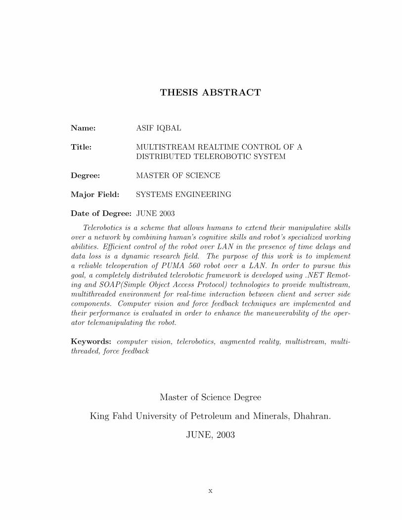
Name: ASIF IQBAL
Title: MULTISTREAM REALTIME CONTROL OF ADISTRIBUTED TELEROBOTIC SYSTEM
Degree: MASTER OF SCIENCE
Major Field: SYSTEMS ENGINEERING
Date of Degree: JUNE 2003
Telerobotics is a scheme that allows humans to extend their manipulative skillsover a network by combining human’s cognitive skills and robot’s specialized workingabilities. Efficient control of the robot over LAN in the presence of time delays anddata loss is a dynamic research field. The purpose of this work is to implementa reliable teleoperation of PUMA 560 robot over a LAN. In order to pursue thisgoal, a completely distributed telerobotic framework is developed using .NET Remot-ing and SOAP(Simple Object Access Protocol) technologies to provide multistream,multithreaded environment for real-time interaction between client and server sidecomponents. Computer vision and force feedback techniques are implemented andtheir performance is evaluated in order to enhance the maneuverability of the oper-ator telemanipulating the robot.
Keywords: computer vision, telerobotics, augmented reality, multistream, multi-threaded, force feedback
Master of Science Degree
King Fahd University of Petroleum and Minerals, Dhahran.
JUNE, 2003
x
��� � ����� ���� �
������ � � � � � � � � � � � � � � � � � ������ � � ��� �"!
# $� � �% �'&(� )� �% � �+*� �,�-%.��� �/ % ��0����1� �2 3 *�4� �% �'5 6 7�8���9 � 7%�#� �:� ��; 3�< 6 =�)%�>�? 2�@��A�$CB'D E �� �E � ,F %�$ ,� �ACG��4� � �7% �� �2� �H�I� � � � � � � � �J�� : # % � , �C7 # K
L�M B ��% �ON�2� �I� � �P+*�) F Q ) MR�S(SUT;
G $WV B � � $ 7 4 AXG $ , F % E � , $+B'D E � A � @ ? 2 % -�; � : # %% �Y[Z\ F 2 M& -�] � 6# > %� ) ^�_ � M� ` L � B � ` 3% �, � _ 2 @ 0$* �, @ � 1
2 A9 , M *ba � % ��c[� 5 � 7 4 2 �edC� G'F A�fgF 0 8ch� B � ` 0 % �� 0 ` F > i jk% l ��& � _ Q d - G 3m
, @ � 1 * � $ jk% l ��& � _ Q dC�en > $ , % � 4Uo % � V *b^ F _ % ��* � 2 4 L 9p��� q9�r�� ) % �Cch� * F sCt L 5 ) u 9% �e&k� 7 v wc � Q � F �p� � 8 3� H s�x F v ? 2 % � 9zy ? � > %m9y ? � % �e� Z K G 3|{ 7 ` % -x F } ) % � � @ ? 2 % ��) K
jk% l �C& � _ Q dC��n > $ , @ � a % � , ^��+� ) A 7 4 AhG $P D ) 0 Q� 3 ) A~k� S< =') 3"�b3 � i � @ F K 5 � 7 $C� A7 4 A[G $ , F % l � , $+B'D[E � A � @ ? 2 > %c � F # v L ; � 7 I 2 � � A(.NET)
9(SOAP)
B � � dC�e\ F 2 F %� 9O� M�Y�Z % � 9 ; � ` 0 % � 9��'9 � 7 8 % ��5 7 4 2 39 � F 0 4 % � Y - G'F � Q � 8 % � G 3 * ��� # 4 % � G�F A * 1 � � 0 % � � $ � o 2 % ��5
; 5 � I % �m, 4 uC� * % � , M Z � 2 % � V ) ��9�j(% l �e��� � ? % � , M � B�3 7 I 2 �2�G 3 5 � 7 4 2 � �e9 V * � s * M ) ^ 2 %7 4 ACG $ � F % !�� Q � _ Q � � 0 4 2 _ M� 0 K � � 5 - � F F v L � L 9m
; ) > 4 % � j w+* 2 _(u � 0 % � , u B 5
u&k5 � 4 0 % � 9X��9 * 2 � > % 7 ` w+� > 0 % � , 4 3 �
&(� * ` : % �p, M 5 ) 4 _ % � , F A * 4 % � , @ > 0U0 % � j Q � � % � fbF A B���'RC��
xi

Chapter 1
Introduction
A telerobot is a machine or device that extends an operator’s sensing and manipu-
lative capability to a remote environment. Specifically a telerobotic system consists
of:
(a) a master arm connected to a client,
(b) a slave arm connected to a server station, and
(c) a stereo-vision system to provide 3D views of slave scene(remote world).
Advanced telerobotic devices are finding numerous application areas in hazardous
environments including those which are:
1. hazardous to humans such as nuclear decommissioning, inspection, and waste
handling; bomb disposal and minefield clearance; unmanned underwater in-
1
2
spection, and search and rescue.
2. those where humans adversely affect the environment such as medical appli-
cations and clean-room operations.
3. those which are impossible for humans to be situated in, such as deep space
and nanorobotics.
Telerobotics is finding applications in these areas because the technology can save
lives and reduce costs by removing the human operators from the operation sites.
However in most of these areas we still need humans in the control loop because
of their very high level of skills and because machine technology is insufficiently
advanced to operate autonomously and intelligently in such complex, unstructured
and often cluttered environments.
Telerobotics has become one of the most rapidly expanding areas in mechanical,
electrical, computer and control systems engineering. Today many industries utilize
robots because they offer advantage of being able to perform set routines more
quickly, cheaply, and accurately than humans. Instead of using programmed routines
to maneuver the robots, telerobotics allows to operate the robot from a distance and
make decisions while telemanipulating the robot in real time. With the development
of more powerful and efficient computers, the future for telerobotics seems extremely
promising. However, it is the flexibility with which these teleoperated robots can be
used that is of great concern to both users and researchers of telerobotics.
3
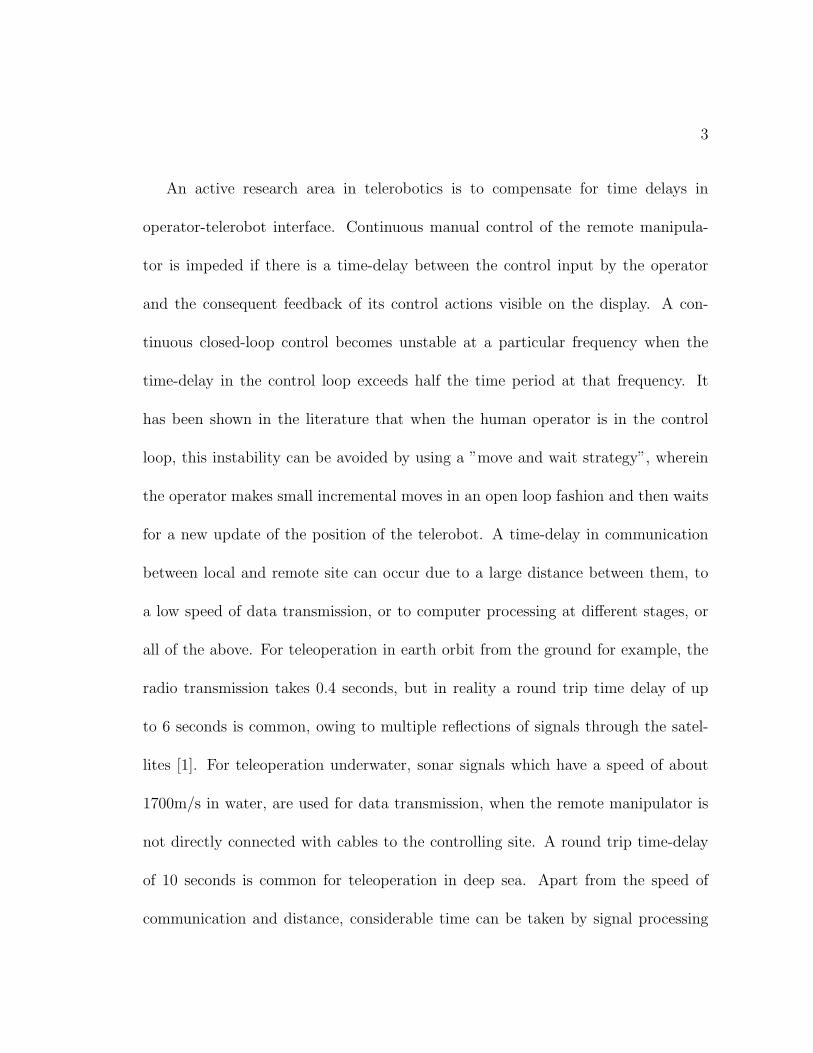
An active research area in telerobotics is to compensate for time delays in
operator-telerobot interface. Continuous manual control of the remote manipula-
tor is impeded if there is a time-delay between the control input by the operator
and the consequent feedback of its control actions visible on the display. A con-
tinuous closed-loop control becomes unstable at a particular frequency when the
time-delay in the control loop exceeds half the time period at that frequency. It
has been shown in the literature that when the human operator is in the control
loop, this instability can be avoided by using a ”move and wait strategy”, wherein
the operator makes small incremental moves in an open loop fashion and then waits
for a new update of the position of the telerobot. A time-delay in communication
between local and remote site can occur due to a large distance between them, to
a low speed of data transmission, or to computer processing at different stages, or
all of the above. For teleoperation in earth orbit from the ground for example, the
radio transmission takes 0.4 seconds, but in reality a round trip time delay of up
to 6 seconds is common, owing to multiple reflections of signals through the satel-
lites [1]. For teleoperation underwater, sonar signals which have a speed of about
1700m/s in water, are used for data transmission, when the remote manipulator is
not directly connected with cables to the controlling site. A round trip time-delay
of 10 seconds is common for teleoperation in deep sea. Apart from the speed of
communication and distance, considerable time can be taken by signal processing
4
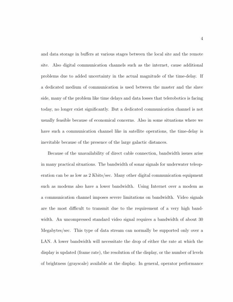
and data storage in buffers at various stages between the local site and the remote
site. Also digital communication channels such as the internet, cause additional
problems due to added uncertainty in the actual magnitude of the time-delay. If
a dedicated medium of communication is used between the master and the slave
side, many of the problem like time delays and data losses that telerobotics is facing
today, no longer exist significantly. But a dedicated communication channel is not
usually feasible because of economical concerns. Also in some situations where we
have such a communication channel like in satellite operations, the time-delay is
inevitable because of the presence of the large galactic distances.
Because of the unavailability of direct cable connection, bandwidth issues arise
in many practical situations. The bandwidth of sonar signals for underwater teleop-
eration can be as low as 2 Kbits/sec. Many other digital communication equipment
such as modems also have a lower bandwidth. Using Internet over a modem as
a communication channel imposes severe limitations on bandwidth. Video signals
are the most difficult to transmit due to the requirement of a very high band-
width. An uncompressed standard video signal requires a bandwidth of about 30
Megabytes/sec. This type of data stream can normally be supported only over a
LAN. A lower bandwidth will necessitate the drop of either the rate at which the
display is updated (frame rate), the resolution of the display, or the number of levels
of brightness (grayscale) available at the display. In general, operator performance
5
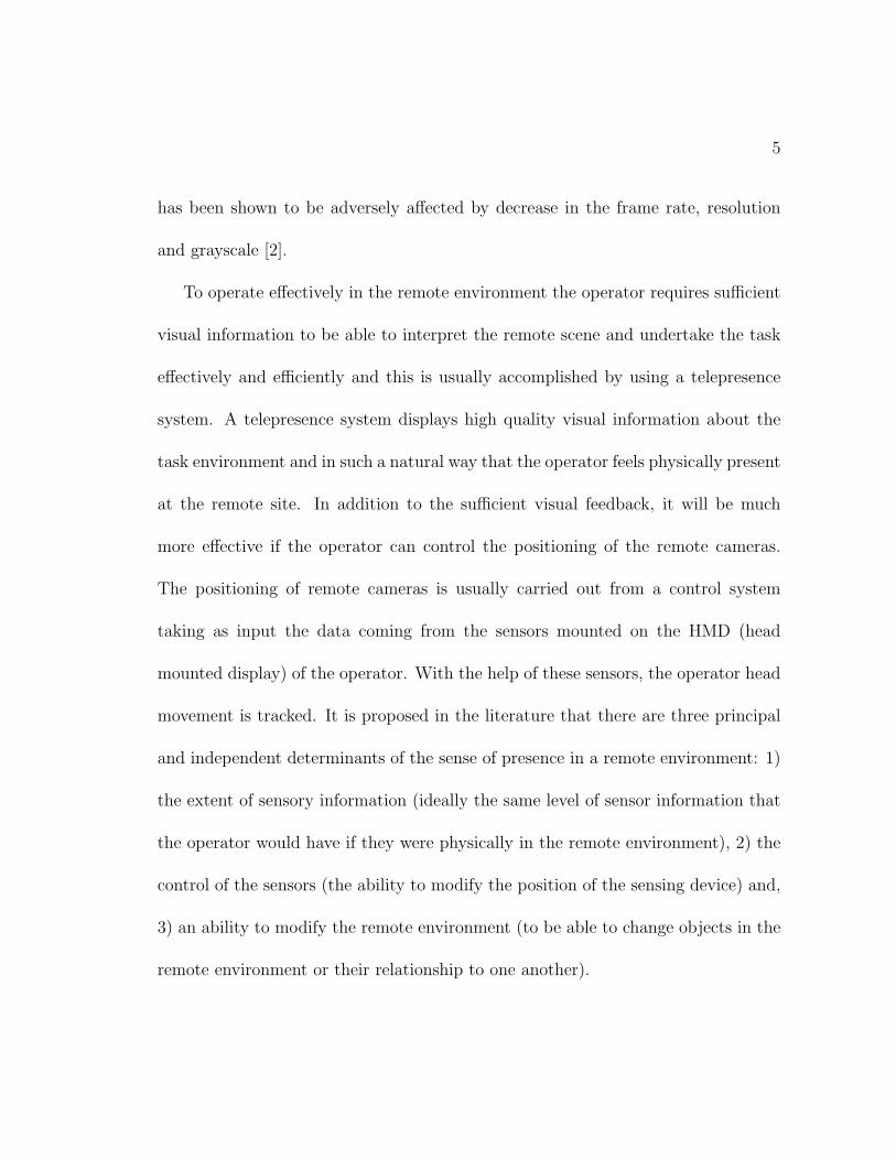
has been shown to be adversely affected by decrease in the frame rate, resolution
and grayscale [2].
To operate effectively in the remote environment the operator requires sufficient
visual information to be able to interpret the remote scene and undertake the task
effectively and efficiently and this is usually accomplished by using a telepresence
system. A telepresence system displays high quality visual information about the
task environment and in such a natural way that the operator feels physically present
at the remote site. In addition to the sufficient visual feedback, it will be much
more effective if the operator can control the positioning of the remote cameras.
The positioning of remote cameras is usually carried out from a control system
taking as input the data coming from the sensors mounted on the HMD (head
mounted display) of the operator. With the help of these sensors, the operator head
movement is tracked. It is proposed in the literature that there are three principal
and independent determinants of the sense of presence in a remote environment: 1)
the extent of sensory information (ideally the same level of sensor information that
the operator would have if they were physically in the remote environment), 2) the
control of the sensors (the ability to modify the position of the sensing device) and,
3) an ability to modify the remote environment (to be able to change objects in the
remote environment or their relationship to one another).
6
From a single observation point, it is not possible to know the real sizes of
objects. 3D positions of points can only be estimated by observing them in at least
two images taken from slightly different viewing angles. This gives rise to the term
stereo vision which is the process of combining multiple images of a scene to extract
3D geometric information. The most basic stereo process uses only two images or a
pair of cameras.
In view of the above discussion, it can be stated that the advancements in teler-
obotics are suffering from the absence of an economical high-bandwidth communi-
cation medium as well as the unavailability of a Q.o.S(Quality of Service) for this
real-time communication. In order to provide an effective and precise real-time in-
terface in a master-slave environment along with the stereo views of the remote
world, the need for a high bandwidth communication channel and guaranteed Q.o.S
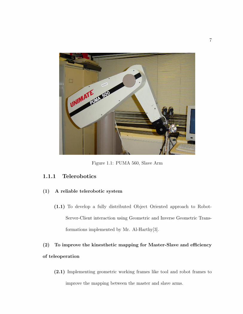
is undeniable. A PUMA 560 robot, as shown in figure 1.1, is used as a slave arm in
this telerobotic framework.
1.1 Thesis Objectives
The thesis work is divided into two major categories:
1. Telerobotics
2. Computer Vision
7
Figure 1.1: PUMA 560, Slave Arm
1.1.1 Telerobotics
(1) A reliable telerobotic system
(1.1) To develop a fully distributed Object Oriented approach to Robot-
Server-Client interaction using Geometric and Inverse Geometric Trans-
formations implemented by Mr. Al-Harthy[3].
(2) To improve the kinesthetic mapping for Master-Slave and efficiency
of teleoperation
(2.1) Implementing geometric working frames like tool and robot frames to
improve the mapping between the master and slave arms.
8
(2.2) Implement a scalable mapping between master and slave spaces. The
scalability can be controlled by operator.
(2.3) Provide the operator with force-feedback display by using a real-time
stream of force information generated from a force sensor and transferred
through the LAN to master station.
1.1.2 Computer Vision
(1) Development of a client-server framework for grabbing, transmission and display
of 3D stereo data over a LAN. 3D effect will be produced using different
methods, like sync-doubling, line blanking and page flipping.
(2) Investigation of Augmented Reality as part of a strategy to reduce network
delays in Telerobotics by using simple pointer in the stereo image at the client
side that is set in a relative position to the current display of the robot gripper
indicating the real-time position of the robot gripper at remote end.
1.2 Organization of the Work
A brief literature survey pertinent to the thesis objectives is given in chapter 2. In
chapter 3, we will discuss a client-server model for the grabbing and transfer of stereo
video data over a LAN. Chapter 4 will cover the design and implementation of a
9
component based distributed telerobotic framework. The details of an Augmented
Reality system for the developed telerobotic framework will be given in chapter 5 .
We conclude in chapter 6.
Chapter 2
Literature Review
Based on the two major areas of this work, the literature review is subdivided into
two main categories.
1. Network Telerobotics
2. Stereo Vision and Augmented Reality
2.1 Network Telerobotics
As defined previously, telerobotics deals with the transfer of human manipulative
skills over to a distant robot. The need for a commodity computer network based
telerobotic system is ever increasing because of the high costs of dedicated com-
munication links between master and slave sites. Network telerobotics is a natural
outcome of such a need. It primarily deals with the issues related to the utilization
10
11
of a computer network, e.g. LAN/WAN, for the development of highly efficient
telerobotic systems.
Paolucci et al.[4] discussed teleoperation on packet switched networks. The ex-
periments are carried out with varying values of data loss, delay and jitter to evaluate
the performance of teleoperation system. It is shown that when the packet size is in-
creased from 64 to 1024 bytes, the network delay is also increased from a mean value
of 5.6 ms to 13.4 ms with a minimum value of delay equal to 5.4 ms always present
due to computational overheads. LAN performs well even in the presence of traffic
caused by other users until the total network congestion, which, of course, causes
the system to be completely unpredictable. But even with a better performance,
Q.o.S guarantee cannot be provided for LAN and Internet. Random time-delays
occur due to the absence of Q.o.S. A real-time process can go unstable when the
time-delay exceeds a certain limit. The performance is more degraded with added
delays and jitter on MAN (Metropolitan Area Networks) possibly due to the pres-
ence of different routers and queuing algorithms.
Teleoperation performance tests are carried out on a network simulator. An impor-
tant result is that the operator performance is quite insensitive to a fairly small data
loss. Also if the same quantity of data is supplied but spaced at regular intervals,
an increase in the operator performance is observed.
Introduction of delay causes a decrease in operator performance almost linearly.
12
Jitter produces a disturbance in velocity due to varying interval between samples.
Introduction of a buffer can decrease the jitter but at the cost of increased delay. A
tradeoff can be negotiated between the two parameters.
A predictive algorithm utilizing the model of the actuator is applied to get better
performance out of the telerobotic system. The model is located at both master
and slave sites. Master site model gives immediate visual feedback to operator en-
hancing his performance while the slave side model is used to periodically update
the parameters of the actuator by comparing the predictive and actual outputs.
Actuator dynamic model is obtained using least square recursive estimator with an
exponential forgetting factor.
Component-based distributed control for tele-operations using DCOM and JAVA is
discussed by Yeuk et al. in [5]. A model-based supervisory control is proposed at
the remote site that is the foundation preparation project at the foot of a volcano
in Japan. In order to fulfill certain requirements such as high level of robustness in
deployment of the complete system and ease in upgrading the system, a component
based distributed control of the system is used. A supervisory control is implemented
at the remote site which is based upon the remote environment model. Internet is
used as communication backbone and JAVA/DCOM are employed to realize compo-
nent infrastructure. Complete isolation from the network protocol is obtained using
components. JAVA and DCOM are used for component development, each one hav-
13
ing some unique characteristics. JAVA is basically an operating system transparent
software language but the use of Virtual Machine makes it a bit slow than OS op-
timized compiled DCOM objects. So DCOM is used in all interface components
except Path Planner GUI and Database interface which are written in JAVA due to
simplicity with no hard real-time constraint. DCOM/ActiveX Supervisory Control
Server is the heart of supervisory system and it maintains communication with ve-
hicle objects, direct manual control as well as sensor integration server components.
Video stream as well as a 3D graphical model of the current remote environment are
provided to the operator. Generally there should not be much difference between
the two, but if there is, the Supervisory Control will transfer the control to the
operator to initiate necessary actions.
Yeuk et al. have further extended their work in [6]. Here the feedback is provided
by two paths, one from the GPS (Global Positioning System) data and the second
one from the visual feedback. The visual feedback is generated by the images from
a camera at the slave site. Here the images are snapped and from the remote en-
vironment models which are identified by Visual Enhancements(VE) , the position
X of the vehicle is determined by minimizing the following error function based on
the difference between the vehicle position coordinates obtained from GPS and the
visual feedback.
14
E =∑
i,jE2ij =
∑i,jKij[Xp(i, j)− PiTcwiTwfi(X)]2 (2.1)
Here Pi, Tcwi, Twfi(.) are coordinate transformation operators and Kij is de-
termined from the reliability of the measurement. This information is used in su-
pervisory control and is also sent to the master site to invoke operator intervention
if any critical error occurs. The system is stated to be sufficiently robust against
the addition of white noise in both robot actuator and camera planes.
A collision-free Multi Operator Multi Robot (MOMR) teleoperation scheme is pro-
posed by Chong et al. in [7]. Effect of time-delay will cause more severe problems
in MOMR systems than in Single Operator Single Robot (SOSR) systems due to
unpredictable nature, in local display, of the slave arm under the control of remote
operator. Due to the presence of long distance in the positions of operators, one can
not get immediately the command issued by the other operator as a result posing
the danger of collision in slave arms. This type of collaboration, known as uncon-
strained collaboration, in which each operator has the freedom to control his/her
slave arm independently from the other slave arm, is very sensitive to time delays.
Operator usually commits to a wait-and-move strategy in order to avoid collisions
thus decreasing the productivity considerably.
Simulation experiments conducted using OpenGL and network delay simulator showed
the occurrence of collisions even when a virtual thickness corresponding to the time-
15
delay is added to the slave manipulator model in local display. There were collisions
even when there was no network delay because of human error. Authors suggest a
new approach using velocity rate control that scales the velocity commands issued
by the operator considering the relative positions of the slave arms. If they are too
near, the velocity commands will be scaled down, otherwise they will be sent as they
are. However if the distance is too small, the velocity commands will become zero
neglecting the operator completely. This approach avoids the collisions completely
but ruins the maneuverability of the joystick because of scaling effect.
Martin Jagersand in [8] proposes an image based predictive display for tele-manipulation.
To obtain a predictive display, normally system modeling is the primal part but in
this method, there is no need of a-priori modeling, instead an image model is gener-
ated from the delayed feedback signals and the command sequence from the operator.
Operator controls the robot by command signals (x1, x2, . . . , ). After some time the
real image stream (I1, I2, . . .) arrives. Due to delay, the operator is seeing image Ik
at time k + d, where d is the delay. Another possibility is to estimate a function
φ(x) online which approximates each image Ii on the trajectory such that
Ii ≈ φk(xi), i ∈ {1, . . . , k} (2.2)
First the image is compressed and is represented in a lower dimensional space of
appearance vectors using an approximately invertible image appearance function g
16
such that I = g(y), where y is the compressed image. To obtain this compression,
KL(Karhunen-Loeve) basis compression is used. Then a function f is learnt such
that y ≈ f(x). This function is initially unknown and can vary during manipula-
tion due to unmodelled kinematics so it is desirable to continuously estimate f . A
recursive Jacobian estimator is used to train f .
Once a reasonable number of images (100-1000) have been obtained, f is sufficiently
trained. So the increment in x, the command signal, is used to estimate the change
in visual appearance. This change is then used to predict the display by forming an
image using the inverse KL approach. The method is suited for applications where
the workspace is small and there are only few changes while moving the manipula-
tor. It is particularly useful where we don’t have geometrical models of the objects.
It is argued that a table lookup approach is not suited for interpolating images in
a real-time application as it will introduce jitter and will require more computation
for the same dimension of the system. The algorithm requires large spatial data to
generate good quality images so it may not be efficient in situations having greater
spatial details.
An effective way of overcoming the varying time-delays in bilateral feedback
systems is discussed by Kazuhiro et al. in [9]. It is already proven in literature that
passivity can be assured in communication block by using scattering transformation.
But variable time-delay destabilizes bilateral master-slave manipulator even with
17
scattering transformation and the authors propose virtual time-delay method to
keep the time-delay constant.
To understand the influence of variable time-delay, suppose that a communication
block has a delay which changes from T to T−dT . If we transmit a sinusoidal signal
via this block, the signal received after the change in time-delay will be changed
abruptly with shift of δu in the amplitude. This makes the communication block
a time-varying system, the passivity of which can’t be guaranteed with scattering
transformation only.
In the method proposed by the authors, the network traffic is observed to get
an estimate of maximum delay, Tc between master and slave. Velocity and force
information are sampled at constant rate and are transmitted to the other side
along with the sampling time tsend. On the other end, the data is received after the
time delay t− tsend which may be shorter than the maximum time delay Tc. If this
is true then these received values are held in a receive buffer until the delay reaches
Tc. At this time, the received values are released from the buffer for manipulation.
In this way we can make the apparent time-delay of the system equal to virtual
time-delay which is constant thus guaranteeing the passivity of the system. Virtual
time-delay can be made to adapt to the traffic condition of the network so that it
remains appropriate in all practical situations.
18
2.1.1 Supervisory Control in Telerobotics
The most recent advances in communications technology are being applied to su-
pervisory control of robots via teleoperation. With automatic control, the machine
controls the process or task, adapts to changing circumstances and makes decisions
in pursuit of some goal. Supervisory control is defined by Sheridan[10], ”in the
strictest sense, supervisory control means that one or more human operators are
intermittently programming and continually receiving information from a computer
that itself closes an autonomous control loop through artificial effectors to the con-
trolled process or task environment.”
Sheridan et al.[11] developed a dynamic user aid to help operators compensate for
several second time delays in telemanipulator systems. The aid, among other ap-
proaches like state prediction, position feedback, etc., also utilized impedance con-
trol thus providing some level of supervisory control in the remote system. The
slave impedance controller provides dynamic disturbance rejection by controlling
the slave/environment interaction. It is shown that the presence of time-delay in
the control loop reinforces the need for appropriate impedance selection. Task plan-
ning and world modelling mechanism as part of a supervisory control scheme is
designed in [12]. The authors manage the complexity of task and error recovery by
hierarchical design of action sequences. The design is implemented in the form of
different modules like sensor fusion, dynamic control and motion planning incorpo-

19
rating reflex for obstacle avoidance. Matthew et al.[13] conducted a teleprogram-
ming experiment incorporating operator supervisory control of a robot performing
puncture and slice operations on the thermal blanket securing tape of satellite re-
pair mission sub-task. The authors assert that in teleoperation research, remote
sites should be remote and that by following this principle, they were able to treat
research issues that could not be entirely anticipated or simulated in a laboratory
setup. They developed a layered architecture controller defining multiple layers of
control. Operator direction interacts as the highest layer of the architecture and
does not affect lower level behaviours of the system.
Christian et al.[14] have shown the necessity of hierarchical supervisory control for
service task solution using a huMan Robot Interface(MRI). They have presented
a distributed planner to control the robot system, enabling both flexible robot be-
haviour and on-line operator support. The presented technique is mainly based on
human or human-like behaviour during routine tasks or in unforeseen or unknown
situations. The behaviour of the proposed intelligent system is separated in four dif-
ferent abstraction levels starting from physical level to the highest level used by the
operator, i.e., knowledge-based level. A semi-autonomous robot system is combined
with a human operator to obtain an intelligent human-robot-system(hierarchical su-
pervisory control).
Tse et al.[15] constructed a remote supervisory control architecture by combining
20
computer network and an autonomous mobile robot. Users having access to WWW
can command the robot through internet. This architecture offers multilevel remote
control modules, namely, direct control, supervisory control and learning control
modes. In supervisory mode, the robot works as a service man who provides the
web users with a specific service. The server receives only a high level command,
then controls the robot to perform the specific task by applying local intelligence
of the mobile robot such as collision avoidance, path planning, self referencing and
object recognition. One of the possible uses of this scheme is stated to be sharing
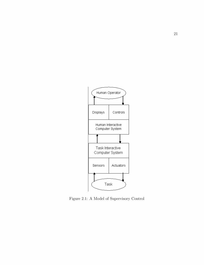
of robot with multi-users via WWW. Sheridan[16] defines a model of supervisory
control. In this model, the operator as a supervisory controller, provides system
commands to a human interactive computer(HIC) which consists of system status
displays and data input devices. HIC passes these goals to the lower level Task
Interactive Computer(TIC) which translates these higher level goals into a set of
commands to the actuators that will produce the desired system performance. A
sketch of this scheme is shown in figure 2.1. A behavior-programming concept to
avoid disturbances of the Internet latency has been proposed by Ren et al. in [17].
They have grouped primitive local intelligence of a mobile robot into motion plan-
ner, motion executer and motion assistant, where each of a group is treated as an
agent. All of these agents are integrated by centralized control architecture based
on multi-agent concept. Event driven approach is applied on the robot to switch the
21
Figure 2.1: A Model of Supervisory Control
22
behaviours to accommodate the unpredicted mission autonomously. For communi-
cation between the client and the server, two virtual channels are used. One for
the transmission of explored information and the other one for the commands. The
high-level behavior-programming control of the networked robot is demonstrated to
be a feasible and reliable method to reduce the interference caused by the Internet
latency.
2.2 Stereo Vision and Augmented Reality
Stereo vision is a technique to capture 3D information of a scene. In robotics, it
is used for 3D viewing/reconstruction of the remote scene in a telerobotic environ-
ment. Augmented reality helps us add additional information with the real data to
supplement the perception of the person using the real data. A review of the work
in stereo vision and augmented reality is presented in the following text.
2.2.1 Stereo Vision
In stereo vision we discuss different aspects of 3D characteristics of a scene. Usually
with stereo vision we mean the visualization of a remote scene in such a way that
the viewer has a clear idea about the relative distances and depths of the objects
present in the stereo image. Stereo vision has a wide range of potential application
areas including; three dimensional map building, data visualization and robot pick
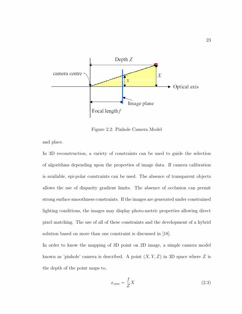
23
Figure 2.2: Pinhole Camera Model
and place.
In 3D reconstruction, a variety of constraints can be used to guide the selection
of algorithms depending upon the properties of image data. If camera calibration
is available, epi-polar constraints can be used. The absence of transparent objects
allows the use of disparity gradient limits. The absence of occlusion can permit
strong surface smoothness constraints. If the images are generated under constrained
lighting conditions, the images may display photo-metric properties allowing direct
pixel matching. The use of all of these constraints and the development of a hybrid
solution based on more than one constraint is discussed in [18].
In order to know the mapping of 3D point on 2D image, a simple camera model
known as ’pinhole’ camera is described. A point (X, Y, Z) in 3D space where Z is
the depth of the point maps to,
xcam =f
ZX (2.3)
24
ycam =f
ZY (2.4)
Homogeneous co-ordinates can be used to express the pinhole camera projection of
3D points to the image plane in the form
x = PX (2.5)
In this case
λ
xcam
ycam
f
=
X
Y
Z
(2.6)
where λ = Zf
, changes to (neglecting the scale factor)
xcam
ycam
f
∼=
1/λ 0 0 0
0 1/λ 0 0
0 0 1/λ 0
X
Y
Z
1
(2.7)
The mapping of the camera points (xcam, ycam) on the image pixel co-ordinates (x, y)
is given by
x
y
1
=1
f
αx 0 x0
0 αy y0
0 0 1
xcam
ycam
f
(2.8)
Or simply,
x = kx . xcam + x0 (2.9)
25
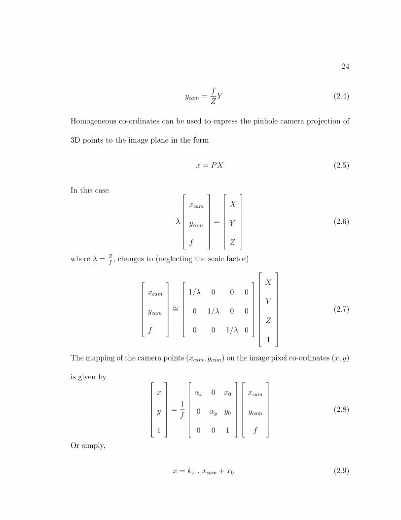
Figure 2.3: Stereo Camera Model
y = ky . ycam + y0 (2.10)
where αx = −fkx and αy = −fky and kx, ky are pixels/length on the camera image
plane. x0 and y0 are the coordinates(on image plane) of the principal point, which
is the projection of camera frame origin onto image plane.
3D camera model can be developed considering figure(2.3). In developing this cam-
era model, we assume the following:
• 2 cameras with their optical axes parallel and separated by a distance d.
• The line connecting the camera lens centers is called the baseline.
• Let baseline be perpendicular to the line of sight of the cameras.
• Let the x-axis of the three-dimensional world coordinate system be parallel to
the baseline

26
• Let the origin O of this system be mid-way between the lens centers.
Using similar triangles,
xlfl
=x+ d
2
z
xrfr
=x− d
2
z(2.11)
where xl, xr are the x-coordinates of the projections of 3D-point x on left and right
image planes while fl, fr are focal lengths of left and right lenses respectively. d is
the disparity or the distance by which two cameras are separated from each other.
Assuming equal focal lengths,
ylfl
=yrfr
=y
z(2.12)
where yl, yr are the x-coordinates of the projections of 3D-point x on left and right
image planes. Now solving for (x,y,z) in the world co-ordinates,
x =d(xl + xr)
2(xl − xr) , y =d(yl + yr)
2(yl − yr) , z =df
xl − xr (2.13)
Based on the expressions for x, y, z in equation(2.13), we can calculate the 3D-
position of a point from corresponding left and right projections of the same point.
In order to use stereo vision to estimate the depth, we need to solve two problems, (1)
correspondence problem, i.e., for all points in the left image, find their corresponding
points in the right image, and (2) using the estimated disparities between the points,
reconstruct the 3D structure of the scene.
3D reconstruction is divided into two sub-areas:
1. Area based stereo
27
2. Feature based stereo
Area based stereo uses algorithms which utilize image domain similarity metrics in
the correspondence process. Further division of area based methods is as follows[19]:
1. Cross-correlation based
2. Least-squares region growing
3. Simulated annealing based
In feature based stereo we are concerned with the algorithms which perform stereo
matching with high level parametrization called image features, these algorithms
can be classified by the type of feature used in the matching process as follows:
1. Edge-string based
2. Corner based
3. Texture region based
2.2.2 Augmented Reality
Augmented Reality (AR) is a variation of Virtual Reality in a sense that AR sup-
plements reality, rather than completely replacing the reality as is the case with VE
(Virtual Environments) or VR. According to Azuma[20], AR systems are required
to have the following three characteristics:
28
1. Combines real and virtual
2. Interactive in real time
3. Registered in 3-D
At least six classes of potential applications have been explored: medical visual-
ization, maintenance and repair, annotation, robot path planning, entertainment,
and military aircraft navigation and targeting. A group at Boeing is developing
AR technology to guide a technician in building a wiring harness that forms part
of an airplane’s electrical system. Boeing currently uses large layout boards to con-
struct such harnesses which can be avoided after AR is implemented in full. See
[21] for details. AR can help annotate objects and environments with public or
private information. Rekimoto[22] proposed such an application where a user gets
information about the contents of library shelves on a hand-held display as he walks
around in the library. Robot path planning can be facilitated using AR in situations
where a large time-delay is present between the operator and the robot. Operator
can preview the effect of the move on the local display over-layed on the remote
world image. Once he is satisfied with the move, he can issue the actual command.
ARGOS[23] toolkit demonstrates that stereoscopic AR is an easier and more accu-
rate way of doing robot path planning than traditional monoscopic interfaces. In
combining the real and the virtual worlds in an AR system, we have two choices:
1. Use optical technology
29
2. Make use of video technology
In an optical AR equipment, we make use of direct see-through, i.e., the operator
gets a direct view of the real world while the virtual objects are super-imposed on
optical see through mirrors in front of his eyes. In video, the operator does not have
any direct view of the real world. He must use the video input from the camera
altered by the local scene generator in order to add virtual objects to the scene.
There are advantages and disadvantages of both the techniques. Further detail can
be found in [20].
One of the basic problems currently limiting AR applications is the registration
problem. The objects in real and virtual worlds must be properly aligned with
respect to each other, or the illusion that the two worlds coexist will be compromised.
Registration errors are difficult to adequately control because of the high accuracy
requirements and the numerous sources of error. There errors can be subdivided
into two types:
1. Static errors
2. Dynamic errors
Static errors are those that cause registration errors even when the user and the
objects in environment remain still. Dynamic errors are only visible when the view-
point starts moving [24]. Static error have four main sources:
30
1. Optical distortion
2. Errors in the tracking system
3. Mechanical misalignments
4. Incorrect viewing parameters(e.g., field of view, tracker-to-eye position and
orientation, interpupillary distance)
For details on static errors and algorithms to rectify them, see [25], [24], [26], [20].
Dynamic errors occur because of system delays or lags. The end-to-end system
delay is defined as the time difference between the moment that the tracking sys-
tem measures the position and orientation of the viewpoint to the moment when
the generated images corresponding to that position and orientation appear in the
displays[20]. System delay is the largest single source of registration error in existing
AR systems, outweighing all others combined [24]. Dynamic registration errors can
be reduced by the methods falling under the following four categories[27]:
1. Reduce system lag
2. Reduce apparent lag
3. Match temporal streams (with video-based systems)
4. Predict future locations
31
2.2.3 Classification of visualization systems based on used
equipment
There is a variety of 3D-video formats, like interlaced, page flipping, sync-doubling,
and line blanking. Each format requires different techniques and/or equipment for
generation and visualization. Furthermore, they have different robustness charac-
teristics under MPEG compression, and image/video resizing. For a detailed and
comparative discussion on these modes, see the online document, Eye3D Manual
[28]. Different ways to generate 3D video content are given as:
1. Parallel camera configurations [29], can be used to observe with high accuracy
a 3D object under magnification and depth. This is a very commonly used
technique for 3D video generation. Computational aspects are simpler than
the tilted case. However, it has problems especially with the near stereoscopic
viewing. Most of the time, some sort of video mixer may be required to convert
two video streams into a single synchronized stream.
2. Tilted camera configurations [30, 31, 32] produce more accuracy in the hori-
zontal direction than in the vertical direction compared to the case of parallel
camera configuration. However, this problem can be overcome by using dif-
ferent horizontal and vertical scaling factors. Furthermore, this configuration
provides a larger area of stereoscopic vision, such that the total area for 3D dis-
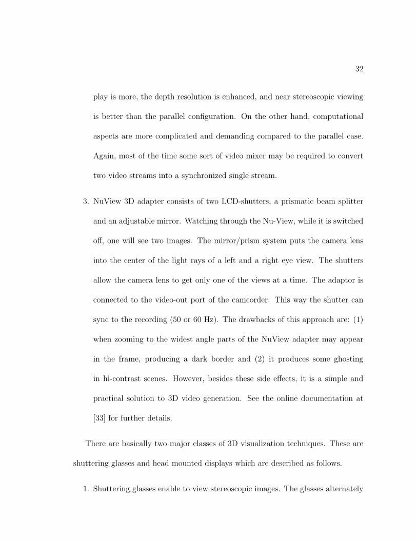
32
play is more, the depth resolution is enhanced, and near stereoscopic viewing
is better than the parallel configuration. On the other hand, computational
aspects are more complicated and demanding compared to the parallel case.
Again, most of the time some sort of video mixer may be required to convert
two video streams into a synchronized single stream.
3. NuView 3D adapter consists of two LCD-shutters, a prismatic beam splitter
and an adjustable mirror. Watching through the Nu-View, while it is switched
off, one will see two images. The mirror/prism system puts the camera lens
into the center of the light rays of a left and a right eye view. The shutters
allow the camera lens to get only one of the views at a time. The adaptor is
connected to the video-out port of the camcorder. This way the shutter can
sync to the recording (50 or 60 Hz). The drawbacks of this approach are: (1)
when zooming to the widest angle parts of the NuView adapter may appear
in the frame, producing a dark border and (2) it produces some ghosting
in hi-contrast scenes. However, besides these side effects, it is a simple and
practical solution to 3D video generation. See the online documentation at
[33] for further details.
There are basically two major classes of 3D visualization techniques. These are
shuttering glasses and head mounted displays which are described as follows.
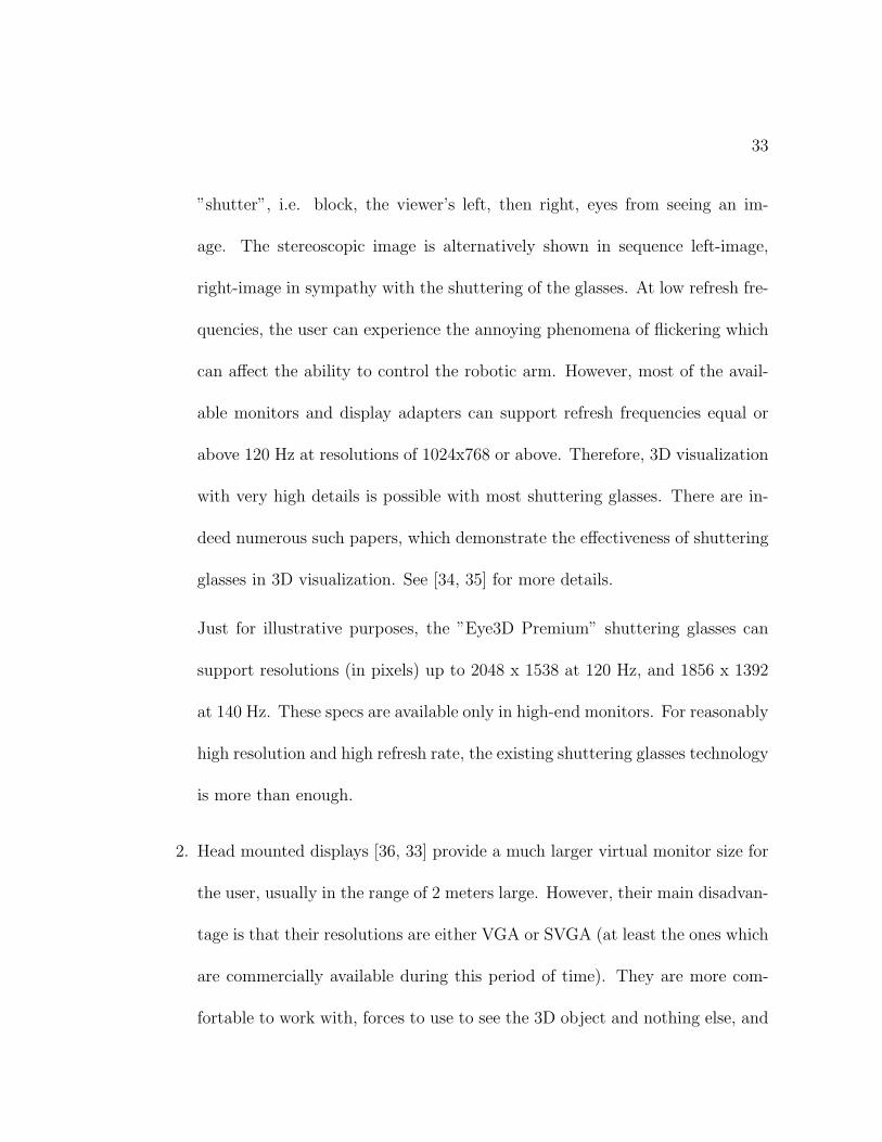
1. Shuttering glasses enable to view stereoscopic images. The glasses alternately
33
”shutter”, i.e. block, the viewer’s left, then right, eyes from seeing an im-
age. The stereoscopic image is alternatively shown in sequence left-image,
right-image in sympathy with the shuttering of the glasses. At low refresh fre-
quencies, the user can experience the annoying phenomena of flickering which
can affect the ability to control the robotic arm. However, most of the avail-
able monitors and display adapters can support refresh frequencies equal or
above 120 Hz at resolutions of 1024x768 or above. Therefore, 3D visualization
with very high details is possible with most shuttering glasses. There are in-
deed numerous such papers, which demonstrate the effectiveness of shuttering
glasses in 3D visualization. See [34, 35] for more details.
Just for illustrative purposes, the ”Eye3D Premium” shuttering glasses can
support resolutions (in pixels) up to 2048 x 1538 at 120 Hz, and 1856 x 1392
at 140 Hz. These specs are available only in high-end monitors. For reasonably
high resolution and high refresh rate, the existing shuttering glasses technology
is more than enough.
2. Head mounted displays [36, 33] provide a much larger virtual monitor size for
the user, usually in the range of 2 meters large. However, their main disadvan-
tage is that their resolutions are either VGA or SVGA (at least the ones which
are commercially available during this period of time). They are more com-
fortable to work with, forces to use to see the 3D object and nothing else, and
34
there is no problem of flickering. Most of them support the INTERLACED 3D
video format, but not the so called ABOVE/BELOW format which is robust
under video compression and resizing. Most HMDs also support page flipping,
but this requires special drivers for each display adapter/chipset.
Some HMDs are also equipped with ear-phones and head trackers, like the
”hiRes-900 + InterTrax2” set available from Cybermind Interactive, the Nether-
lands. But compared to shuttering glasses, they are a factor of 10-20 or more
times expensive, yet they are limited to SVGA resolutions.
2.2.4 Classification of visualization systems based on delay
and bandwidth
Dealing with network transmission delays and limited network bandwidth is a funda-
mental research problem in telerobotics. Introduction of time delays into a general
control system poses problems related to stability and performance. This is also
true for a telerobotics system. It has been reported that operators confronted with
time-delay had a tendency to move by small increments and wait to see the results of
their motion, i.e. using the ”Move and wait” strategy. This approach considerably
reduces the overall system performance.
In [37], a telerobot at Jet Propulsion Labs (JPL) is described. It has been
reported that a 5 milliseconds delay is too small for the operator to notice. This is

35
called as the ”normal” mode and it provides high fidelity and stable performance.
However, as the delay is increased up to 1/4 seconds, it starts to be noticeable by the
operator, and this starts to affect his cognitive task and motion planning. Delays
as small as 1 second, considerably degrade the operator’s performance.
For some space applications it is desirable to control the space manipulator from
Earth. This introduces unavoidable time delays in data links between the master
and slave systems. Round-trip communication times can be as large as 6 seconds.
When faced with such a large delay, the operator needs some support to overcome
the lack of frequent interaction with the remote site in an attempt to improve the
timing and correctness of the task execution.
In the following, we briefly describe three visualization approaches. They indeed
differ on the way that they address the issues of delay and bandwidth.
1. One Way Image/Video Transmission Based Methods [38, 39, 40, 41, 42, 43, 44,
45] consists of sending static images or live video from the slave robot location
to the display(s) at the master arm location. In this simplistic approach,
the only effort done to reduce transmission delays is to compress the static
images or use some video compression techniques. In any case, there will be
a long delay between the actual slave scene and what is seen at the master
station. This is a feasible solution only if the master station can issue high-
level operator commands and there is a local controller at the remote slave
36
location to interpret these commands. A typical command might look like
”Move 5cm in the North direction”, ”Open the gripper”, etc. The operator
interaction in such systems is usually minimized by the use of short actions
that automatically executes at the slave site without involvement of the remote
operator.
2. The Model-Based Methods [46, 47] consists of using graphical tools to super-
impose a picture of the slave robot scene with a generated background image
at the display of the master robot site. The ARGOS (Augmented Reality
through Graphic Overlays on Stereo-video) project is one example for this ap-
proach. Transmission of static images and/or live video generally introduces
delay and consumes a significant portion of the available bandwidth. This is
also the case even if advanced image and video compression techniques are
used to overcome the effects of delay and low bandwidth. The model based
methods use Augmented Reality (AR) or Virtual Reality (VR) tools to draw
the slave robot arm picture on a real or computer generated background image
at the master stations display unit. For this a complete and accurate model
of the slave robot arm is used at the master station. The slave station is sup-
posed to send position and orientation parameters of the slave robot arm to
the master station in a continuous manner. Based on these received parame-
ters, the master station can draw an artificial image (graphically computed) of
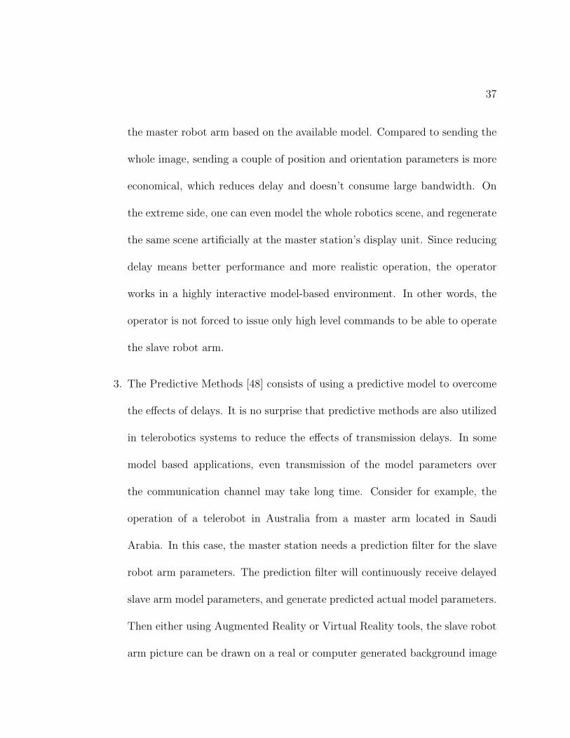
37
the master robot arm based on the available model. Compared to sending the
whole image, sending a couple of position and orientation parameters is more
economical, which reduces delay and doesn’t consume large bandwidth. On
the extreme side, one can even model the whole robotics scene, and regenerate
the same scene artificially at the master station’s display unit. Since reducing
delay means better performance and more realistic operation, the operator
works in a highly interactive model-based environment. In other words, the
operator is not forced to issue only high level commands to be able to operate
the slave robot arm.
3. The Predictive Methods [48] consists of using a predictive model to overcome
the effects of delays. It is no surprise that predictive methods are also utilized
in telerobotics systems to reduce the effects of transmission delays. In some
model based applications, even transmission of the model parameters over
the communication channel may take long time. Consider for example, the
operation of a telerobot in Australia from a master arm located in Saudi
Arabia. In this case, the master station needs a prediction filter for the slave
robot arm parameters. The prediction filter will continuously receive delayed
slave arm model parameters, and generate predicted actual model parameters.
Then either using Augmented Reality or Virtual Reality tools, the slave robot
arm picture can be drawn on a real or computer generated background image
38
at the master station’s display unit by using the parameters output from the
prediction filter, not by using the received delayed ones. As in the model based
case, predictive methods increase level of operator interaction and give a more
realistic sense of teleoperation.
Chapter 3
The Client-Server Framework for
Stereo Image Acquisition
In a tele-operated environment, the operator needs to know the most recent situation
at the server (or remote) side in order to make efficient manipulative decisions to
control the robot. This information can be of more than one types, visualization
being one of them. By this approach we provide the operator with a pictorial view
of the remote side thus giving him a way to see the effect of his control commands.
Using stereo image techniques allows the operator to estimate the relative distances
among the remote objects or to feel the depth of the scene. It has been shown in the
literature that these techniques greatly enhance the operator’s efficiency during tele-
manipulation. However, this allowance of stereo image on the client side imposes
39
40
severe requirements in terms of bandwidth to transfer real-time stream of video
data in a client-server environment. In addition it also requires the use of advanced
technologies like DirectX and Windows Sockets to accomplish the capturing and
relaying of video data over a LAN. Commercially available softwares like Microsoft
NetMeeting are optimized for a low band-width network like internet so they show
too poor display resolution to be used for stereo vision in a telerobotic setup.
Development of a highly optimized client-server framework for grabbing and relaying
of a stereo video stream becomes inevitable keeping in view the above discussion.
This framework must accomplish the following tasks;
Server Side
1. Capture or grab stereo images from two cameras at the slave side simultane-
ously.
2. Establish a reliable client-server connection over a LAN, the slave side being
the server.
3. Upon requests from the client send this stereo frame comprising of two pictures
to the client through windows sockets.
Client Side
1. Establish a highly optimized fast graphic display system to show the pictures
received from the server.
41
2. Detect and establish the connection with server.
3. Display the pictures arrived from the server and continue in a loop each time
asking a new stereo frame from the server.
4. Allow the viewer to adjust the alignment of the pictures on the output device,
whatever it is, to compensate for the misalignment and non-linearities present
in the stereo camera setup at server side.
A client-server framework fulfilling the above defined requirements is developed us-
ing the most advanced software development tools like Microsoft Visual C# and
Microsoft DirectX. A detailed description of its functional and implementation de-
tails follows.
3.1 Functional Details
The functional design of this distributed framework can be split into two sections;
• Server Side
• Client Side
3.1.1 Server Side
Microsoft DirectX provides COM based interfaces for various graphics related func-
tionalities. DirectShow is one of these services. DirectShow, further, provides effi-
42
����� �������� � ������ ��������� � � � � �� �
� � � !� � � "
#$&%'�( ) * +,( ) *$.- ) /
0�1 2�3 ����4�� �
������ ��������� � � � � �� �� � � !� � � "
#$&%'�( ) * +,( ) *$.- ) /
5�6�7
8 9 : ; < = >@? A B ; > = C 9 D: B >E�= 9 F F > = G < B B H > I J > = > =
8 9 : ; < = >@? A B ; > = C 9 D�: B >E�= 9 F F > = G < B B H > I J > = > =
K L M@N O P Q RS T U Q V W
X > Y ; C 9 D@: B > Z
H A [ \ ;C 9 D�: B > Z
]&^ _ ` a b c�d d ]&^ _ ` a b e�f g h
Figure 3.1: Block Diagram of Sample Grabber
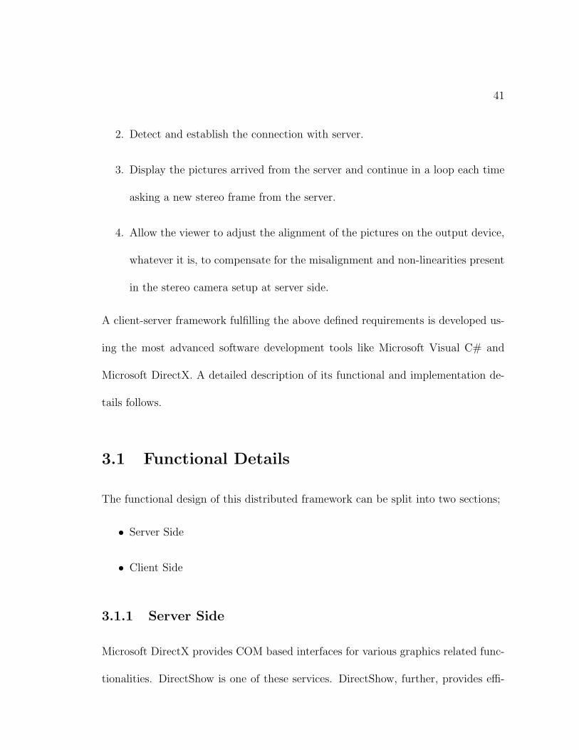
cient interfaces for the capturing and playback of video data. In our scheme we use
a component of DirectShow named SampleGrabber to capture video frames coming
through a stream from a stereo camera setup. A block diagram of the scheme used
at the server side to grab stereo frames is shown in figure 3.1. Here the images from
the left and right cameras are transferred to the PC using Sony’s iLink interface
which is based on IEEE 1394 serial bus standard (also known as FireWire) at a data
rate reaching 400 Mbps. This stream is converted to DM(Digital Media) by a PCI
card that hosts FireWire input ports for devices using FireWire standard. After that
we hook capture filters provided by DirectShow to get hold of the video stream from
the cameras. Once we have video stream, the SampleGrabber is attached to capture
the video samples from the stream. For termination purposes a null renderer is used
to end the stream. If required, a renderer filter can be used to display the video on
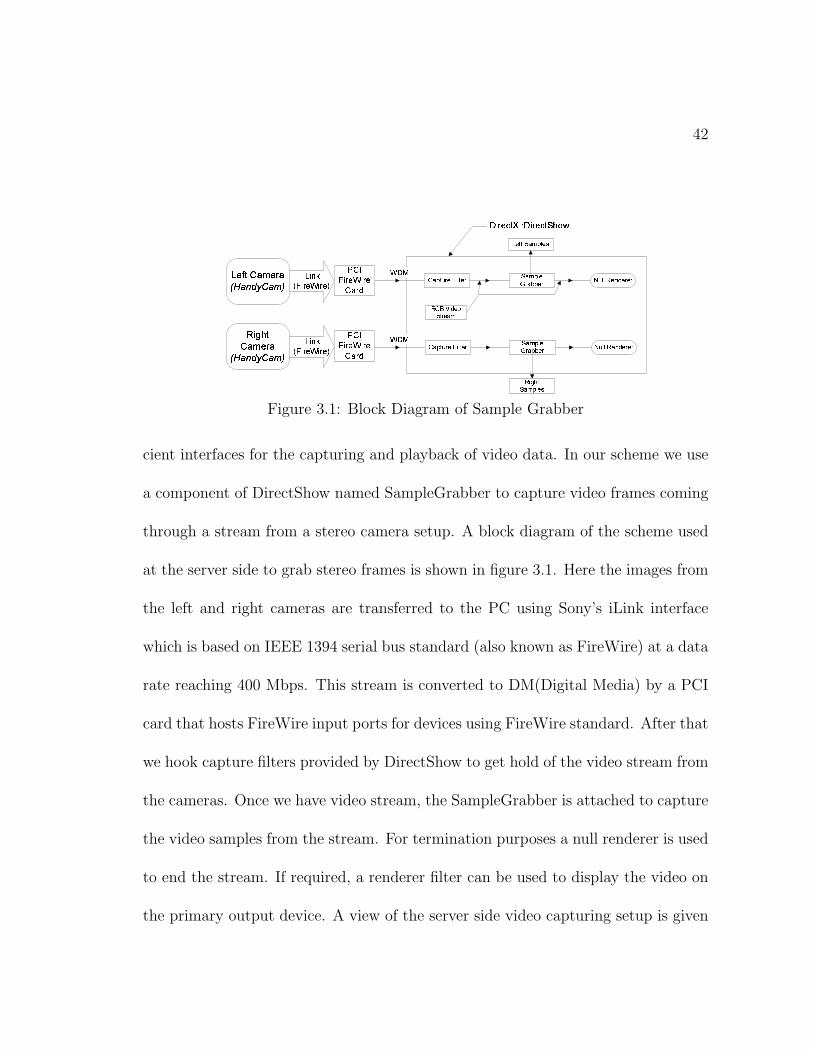
the primary output device. A view of the server side video capturing setup is given
43
Figure 3.2: Video capturing station
in figure 3.2.
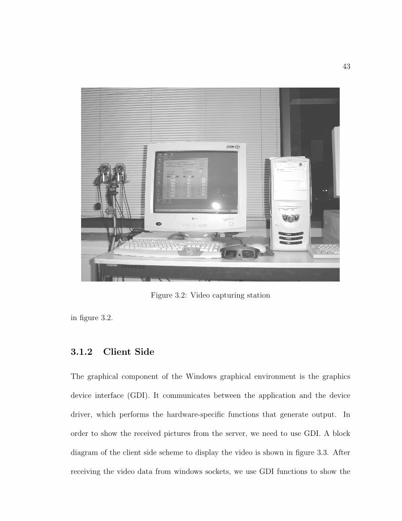
3.1.2 Client Side
The graphical component of the Windows graphical environment is the graphics
device interface (GDI). It communicates between the application and the device
driver, which performs the hardware-specific functions that generate output. In
order to show the received pictures from the server, we need to use GDI. A block
diagram of the client side scheme to display the video is shown in figure 3.3. After
receiving the video data from windows sockets, we use GDI functions to show the
44
������� ��
� ��� �� �����
��� ������� ������
�����!"��#�$ �%�&��'�� �%(��
�����!"��#�$ �%�&��'�� �%(�� ) ����$ '+*,�$ '��
) ����$ '+*,�$ '��
),- $ � ) $ �
),- $ � ) $ � .,'�/0*���$ '%�
.,'�/1*,�$ '%�
+!2 �3 �4 �56�$ �%�!"��#�$ � �1 '�� �4 � ��%��7
Figure 3.3: Displaying the stereo picture on client side
picture on the monitor screen.
3.2 Implementation
In order to implement the above described client-server interface, we need a LAN
to carry out the transfer of video data. In Windows environment, Sockets are used
to program the network applications or in other words, we can use network services
and send/receive data over a network using windows sockets.
Windows sockets are further subdivided into two major categories, known as (1)
synchronous windows sockets and (2) asynchronous windows sockets. Synchronous
and asynchronous refer to whether a network call on the socket is blocking or non-
blocking. The stereo video setup uses synchronous windows sockets as an interface
between vision server and client. Two different schemes were implemented to trans-
fer the video data. The schemes differ in the usage of multiple threads on the server
45
����� �����
��� � ��� � ������� ��� ������ ���� �������������
� ��"!$#�%�&')(+*
, -./ 012 31 045 6.0
, -./ 012 31 045 6.0
798 � ����
: ; < = >�? @ A >B)C D�E F C�? < G G E F =
H I JK E L < E = A
MNF C OP�Q�KI D�C R E =�< = I S RT C DU ; EM�F C O O E F
B)C ; ; O C J V: < S J A I @ S
BWF E C A E X @ I S A? I A DNC U�Y E C Z E FC S Z�? < G G E F
T E S Z�H I J A < F E�A @BW; I E S A
[ \ ] ^ ] _ ` ] a bcdW[
d)b ^ b e ^ _ \ fg h ^ _ i ` ] h j�k l mlWn \ \ b e ^ ] n \
o b \ f�mW] ep)b q r b h ^
s�t u v w
x)n n y�o _ z�{ ` bc�| _ i i b |)lW_ ` ` i _ e y
} r \ e ^ ] n \
lWn \ \ b e ^ ~W] f b no n r | e b h
o)b ^ r {�dW] | b e ^ o)j n �
pWr \�} ] ` ^ b | c�| _ { j
o)b ^ r {�_ \ f�h ^ _ | ^k l m�o b | � b |
^ j | n r � j�o)n e y b ^ h
� C A C�WF F I � E Z
MNE A ? I A D�C UY E C Z E F C S Z? < G G E F T)I � EBWF E C A E�� D�U A �
? I A D�C U
MNE A ? I A D�C U? < G G E F G F @ D9� BNHT A F E C D�I S A @� D�U A ��? I A DNC U
�)I = U ; C ��H I J =
T E S Z�H I JK E L < E = A
o b | � b | h ] f b�` n n { l ` ] b \ ^ h ] f b�` n n {
s�t)u v w
Figure 3.4: Streaming Stereo Video over LAN
side as well as some optimization steps to reduce the network traffic for the transfer
of the data.
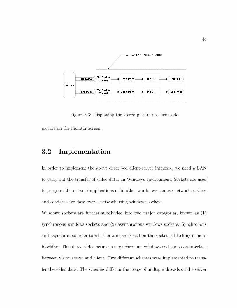
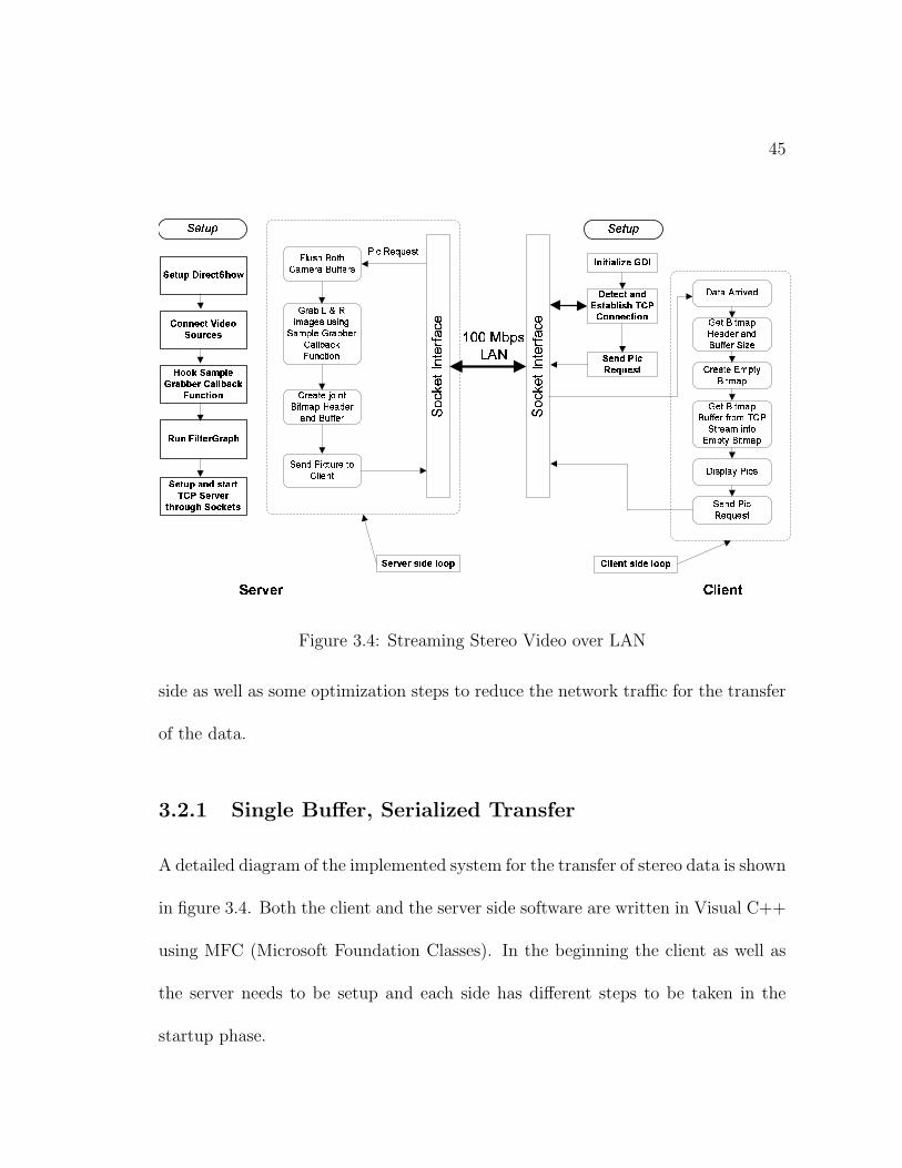
3.2.1 Single Buffer, Serialized Transfer
A detailed diagram of the implemented system for the transfer of stereo data is shown
in figure 3.4. Both the client and the server side software are written in Visual C++
using MFC (Microsoft Foundation Classes). In the beginning the client as well as
the server needs to be setup and each side has different steps to be taken in the
startup phase.
46
On the server side the DirectShow environment is initialized and after that we
connect the two video cameras to this environment by the scheme drawn in figure
3.1. The SampleGrabber component of DirectShow uses a callback function to
inform the completion of one video frame. In the stereo case we have two instances
of SampleGrabber running at the same time to capture the video coming from two
sources. Once the SampleGrabber executes this callback function, we can then copy
this data supplied by SampleGrabber to some global memory buffer to be sent to
the client through sockets. Microsoft does not recommend the sending of video
data on to sockets directly from the callback function because it blocks the user
interface of certain versions of Windows OS. After the hooking of callback function
onto SampleGrabber, we initialize FilterGraph, another component of DirectShow,
which starts the video capturing. The last step of server initialization is the setup of
a server socket to send the video data over LAN. Once this initialization procedure
is over , the server waits for a request of picture from the client to initialize sending
video data.
On the client side the initialization is a bit simple as we initialize GDI (Graphics
Development Interface) to be able to draw the received pictures on the client screen.
After the GDI is initialized, the sockets are hooked to check the presence of the
server on LAN, and if found, to issue a request for the picture to the server. This
completes the initialization process on the client side.
47
After the client has sent a request for the picture to the server, both the client and
the server enter respective local loops. The server side loop continues to receive the
requests from the client, flush the previous bitmap buffers, grab left and right images
using callback functions, create a Bitmap information header for these images and
send it through the sockets over the LAN to the client.
The client side loop gets the buffer size from the TCP stream, prepares the bitmap
buffer, receives the bitmap information header, copies the bitmap data from the
sockets into the buffer, requests for new picture, draws the stereo picture on the
screen to be viewed in 3D.
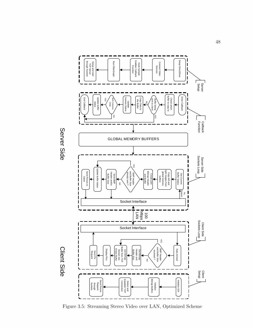
3.2.2 Double Buffer, De-Serialized Transfer
In this scheme, we try to optimize the transfer of video data over the LAN by using
some thread manipulation on the server. Specifically speaking, thread overlapping
among capture and sending thread is achieved using double buffers on the server
side. In this way, it is ensured that the thread responsible for sending the video
data over the LAN will not wait after receiving a picture request from the client.
A detailed diagram of the new scheme is shown in figure 3.5. By having a look
at the figure, it is clear that the server side setup is not changed. Rather we have
allocated two buffers, one for each stereo frame on the server. Every time a picture
is received, the callback function of the respective camera is invoked. Once inside
48
Server S
ide
100 M
bps LA
N
S o c k e t I n t e r f a c e
S o c k e t I n t e r f a c e
Get C
urrent
Buffer S
tatus
Copy left and
right images from
global m
emory
buffers
Create joint
Bitm
ap Header
and Buffer
Update buffer status
Initialize GD
I
Detect and
Establish T
CP
C
onnection
Send P
icture R
equest
through S
ockets
Data A
rrived
Get B
itmap
Header and
Buffer S
ize
Get B
itmap
Buffer from
TC
P
Stream
into E
mpty B
uffer
Display P
ics
Send P
ic R
equest
Hook S
ample
Grabber C
allback F
unction
Connect V
ideo S
ources
Setup D
irectShow
Run F
ilterGraph
Setup and start T
CP
Server
through Sockets
Enter C
allback
Check w
hich buffer to copy to
Copy D
ata to the B
uffer
Buffer being
sent to client
YE
S
NO
Update buffer
status
Both C
ameras
ready
YE
S
NO
Exit C
allback
Update
Cam
era Status
Callback
Function
G L O B A L M E M O R Y B U F F E R S
Send P
icture to C
lient
BM
P H
eader and B
uffer Size
already sent ?
YE
S
Send B
MP
H
eader and/or
Buffer S
ize
Pic.
Request
NO
Client
Setup
Initialize
Bitm
ap Buffers
BM
P H
eader and B
uffer Size
received ?
YE
S
NO
Client S
ide S
ockets Loop S
erver Side
Sockets Loop
Server
Setup
Client S
ide
Figure 3.5: Streaming Stereo Video over LAN, Optimized Scheme
49
the callback function, it accesses a shared variable among multiple threads which
indicates which buffer was copied to in the previous successful callback of this very
camera. By ”successful” we mean that there are callback invocations in which no
data will be copied to the memory buffer. An example of this case is the situation in
which camera 1 copied data to buffer b1,c1. Subscript 1, c1 stands for 1st buffer out
of double buffers and further that this portion of the buffer is related to camera 1.
After the copying operation, the sending thread accessed b1,c1 and started sending
data over LAN. In this duration, if camera 1 finished copying to the second buffer,
i.e., b2,c1 , it will come back to b1,c1 to write the next frame. But after accessing
the buffer status variable, it will be denied access to this buffer as its transfer is
still underway over the LAN. The camera will immediately return from the callback
function. This will be attributed to an unsuccessful callback.
After copying the data to the buffer, it will further update the status of the camera.
The status of the camera is required to synchronize the stereo frames for the left
and right pictures. If both cameras are ready, it will update the buffer status which
will enable the sending thread to send this buffer over to the client. In case the
second camera has not finished copying the picture to the buffer, buffer status is not
updated.
The sending thread is responsible for receiving requests from the client. After it
receives a request, it will check the buffer status to determine which buffer should
50
be sent. Once the proper stereo buffer is determined, it will create Bitmap headers
and retrieved the buffer size. If these information have not already been sent to the
client, they are sent. Otherwise, the server continues with the sending of buffer data
only. The client proceeds in the same manner as with single buffer approach except
that it does not receive the Bitmap information header and buffer size with each
stereo frame. It retains the Bitmap Information Header and buffer size to properly
display and read the required number of bytes from windows sockets.
This approach enables us to send higher number of stereo frames over the same
LAN and hardware. The only overhead is the allocation of extra buffer in the server
DRAM which is not a real problem with available systems containing large memory.
3.3 3D Visualization
There can be different methods to produce 3D effects on the client side. Once we
have two stereo images of the remote scene. The following two methods are used
extensively to accomplish this task;
• Sync-Doubling
• Page Flipping
51
3.3.1 Sync-Doubling
Sync-doubling does not require any special device inside the computer. We only
need to arrange the left and right eye images up and down on the computer screen.
A sync-doubler sits between the display output from the PC and the monitor to
insert an additional frame v-sync between the left and right frames (i.e. the top
and bottom frames). This will allow the left and right eye images to appear in an
interlaced pattern on screen. Using the frame v-sync as the shutter alternating sync
allows us to synchronically transmit the right and left frames to respective left and
right eyes, thus creating a three-dimensional image. This is the most effective 3D
presentation method. It is not limited by the computer hardware specs or by the
capabilities of the monitor. However, sync-doubling is limited in a way that we get
only half of the resolution of the screen for the 3D image.
3.3.2 Page Flipping
Page-flipping means alternately showing the left and right eye images on the screen.
Combining the 3D shuttering glasses with this type of 3D presentation only requires
the application of frame v-sync as the shutter alternating sync to create a 3D image.
Page-flipping requires higher hardware specifications.
• Since synchronized registration of left and right eye frames is necessary, the
minimum capacity of its frame buffer is twice as usually required.
52
• In order to overcome the ”flashing” problem of 3D imaging, frames provided
should be at least 60 frames per second; hence v-scan frequency should be
120Hz or higher.
• As it involves hardware frame buffer and page-flipping synchronization, it often
requires specially designed hardware for double-buffering the stereo image.
Page-flipping provides full resolution picture quality, hence it has the best visual ef-
fect among all available 3D display modes. But being highly dependent on software
and hardware is the biggest drawback of this technique.
Because of the easy availability of sync-doubling shuttering glasses and minimal
dependence on hardware, we have used sync-doubling technique as a provider of
3D visualization on the client side. A pair of stereo pictures is drawn on the client
screen and the sync-doubler is hooked between the monitor and the VGA output.
If the operator does not feel the 3D effects due to the camera calibration problems,
a keyboard interface is given on the client side to move the pictures relative to each
other to compensate for the camera setup problems until he gets a complete 3D view
of the remote scene.
53
3.3.3 Output Devices for 3D Visualization
Mainly two types of devices are used for 3D vision systems, (1) shuttering glasses
and (2) HMDs (Head Mounted Displays). The principle of the shuttering glasses is
to show each eye a different images, i.e., left image to the left eye and right image
to the right eye, by alternatively shuttering LCD glasses worn by the viewer. This
way the human brain gets the illusion of viewing two different(stereo-scopic) views
at the same time.
HMDs have a different approach. They are wearable displays and to each eye a
separate LCD screen is shown. Some HMD display also come with head movement
trackers to help aid in 3D orientation.
We use eye shuttering glasses with a display resolution of 1024 by 768 pixels and
refresh rate of 85 hertz which is doubled to 170 hertz by the sync-doubler. The
stereo image resolution attained is 288 by 360 pixels. A resolution of 384 by 512
pixels can be achieved with current monitor settings but this will introduce more
load on network traffic thus decreasing the frames per second and in turn increasing
the inter-arrival times.
3.4 Performance Evaluation
Different experiments were conducted to test the visual quality of the client-server
setup as well as to find the time delays and other measures of the video data. The
54
validity of the data obtained during the experiments was verified by conducting
several experiments with same configuration and by checking the differences in the
results.
The specifications of the stereo frame are as under:
Height of each picture = 288 pixels
Width of each picture = 360 pixels
Size = 304 KB (311040 Bytes) per picture
= 608 KB (622080 Bytes) per stereo frame
So each stereo frame is of size 0.6 MB and requires a bandwidth of 5Mbps/Frame
on the LAN. This simple calculation shows the limitation of the 100 Mbps LAN to
transfer only 20 fps (frames per second) at the highest possible transfer rate.
3.4.1 Copying from SampleGrabber to DRAM
First we consider the server side to find out the time to copy one stereo frame from
the SampleGrabber to the DRAM. A high precision counter was used to count the
cpu ticks between the start and end of the frame copy.
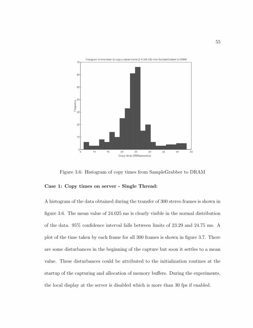
55
Figure 3.6: Histogram of copy times from SampleGrabber to DRAM
Case 1: Copy times on server - Single Thread:
A histogram of the data obtained during the transfer of 300 stereo frames is shown in
figure 3.6. The mean value of 24.025 ms is clearly visible in the normal distribution
of the data. 95% confidence interval falls between limits of 23.29 and 24.75 ms. A
plot of the time taken by each frame for all 300 frames is shown in figure 3.7. There
are some disturbances in the beginning of the capture but soon it settles to a mean
value. These disturbances could be attributed to the initialization routines at the
startup of the capturing and allocation of memory buffers. During the experiments,
the local display at the server is disabled which is more than 30 fps if enabled.
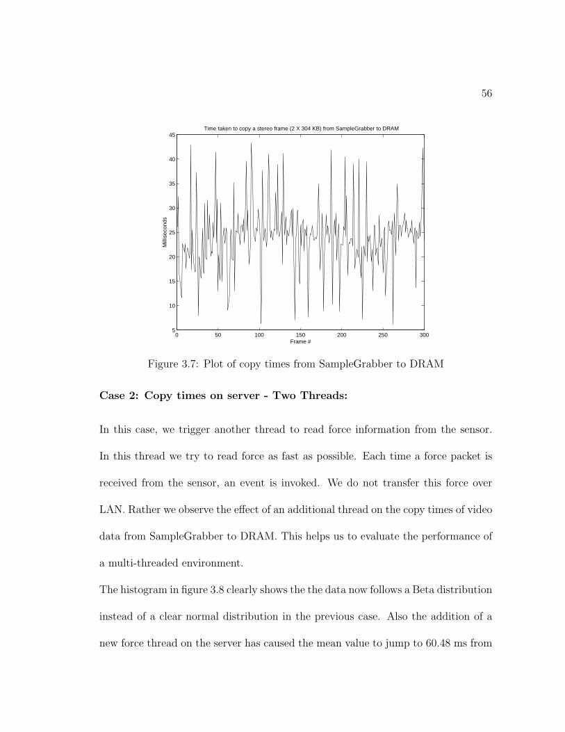
56
0 50 100 150 200 250 3005
10
15
20
25
30
35
40
45Time taken to copy a stereo frame (2 X 304 KB) from SampleGrabber to DRAM
Frame #
Mill
isec
onds
Figure 3.7: Plot of copy times from SampleGrabber to DRAM
Case 2: Copy times on server - Two Threads:
In this case, we trigger another thread to read force information from the sensor.
In this thread we try to read force as fast as possible. Each time a force packet is
received from the sensor, an event is invoked. We do not transfer this force over
LAN. Rather we observe the effect of an additional thread on the copy times of video
data from SampleGrabber to DRAM. This helps us to evaluate the performance of
a multi-threaded environment.
The histogram in figure 3.8 clearly shows the the data now follows a Beta distribution
instead of a clear normal distribution in the previous case. Also the addition of a
new force thread on the server has caused the mean value to jump to 60.48 ms from
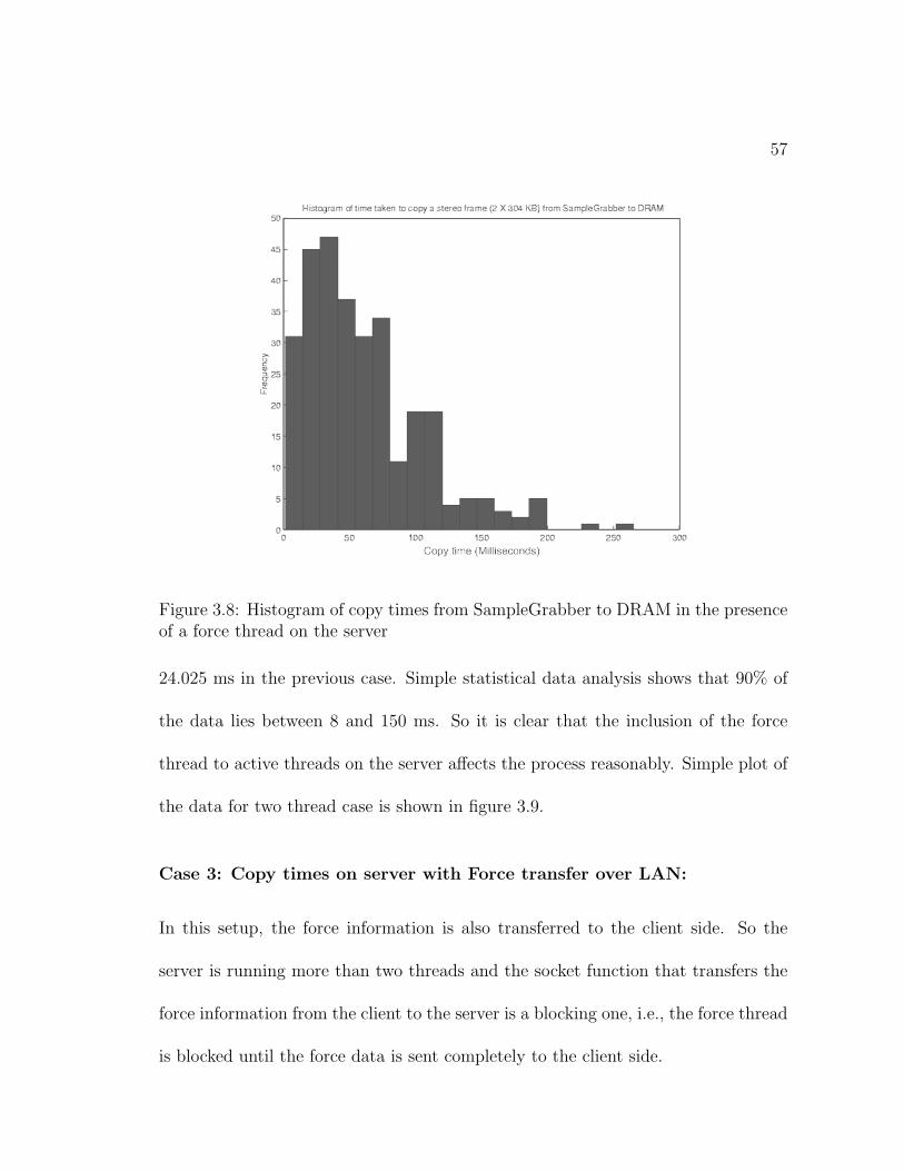
57
Figure 3.8: Histogram of copy times from SampleGrabber to DRAM in the presenceof a force thread on the server
24.025 ms in the previous case. Simple statistical data analysis shows that 90% of
the data lies between 8 and 150 ms. So it is clear that the inclusion of the force
thread to active threads on the server affects the process reasonably. Simple plot of
the data for two thread case is shown in figure 3.9.
Case 3: Copy times on server with Force transfer over LAN:
In this setup, the force information is also transferred to the client side. So the
server is running more than two threads and the socket function that transfers the
force information from the client to the server is a blocking one, i.e., the force thread
is blocked until the force data is sent completely to the client side.
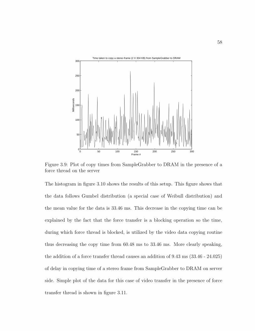
58
0 50 100 150 200 250 3000
50
100
150
200
250
300Time taken to copy a stereo frame (2 X 304 KB) from SampleGrabber to DRAM
Frame #
Mill
isec
onds
Figure 3.9: Plot of copy times from SampleGrabber to DRAM in the presence of aforce thread on the server
The histogram in figure 3.10 shows the results of this setup. This figure shows that
the data follows Gumbel distribution (a special case of Weibull distribution) and
the mean value for the data is 33.46 ms. This decrease in the copying time can be
explained by the fact that the force transfer is a blocking operation so the time,
during which force thread is blocked, is utilized by the video data copying routine
thus decreasing the copy time from 60.48 ms to 33.46 ms. More clearly speaking,
the addition of a force transfer thread causes an addition of 9.43 ms (33.46 - 24.025)
of delay in copying time of a stereo frame from SampleGrabber to DRAM on server
side. Simple plot of the data for this case of video transfer in the presence of force
transfer thread is shown in figure 3.11.
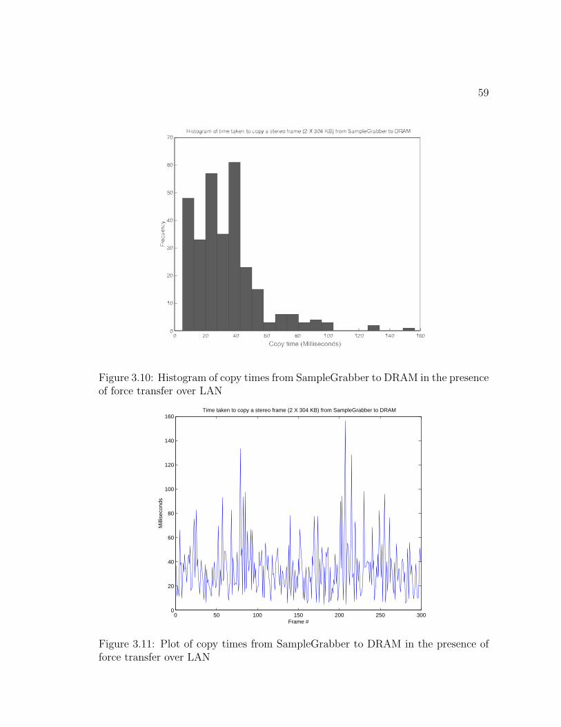
59
Figure 3.10: Histogram of copy times from SampleGrabber to DRAM in the presenceof force transfer over LAN
0 50 100 150 200 250 3000
20
40
60
80
100
120
140
160Time taken to copy a stereo frame (2 X 304 KB) from SampleGrabber to DRAM
Frame #
Mill
isec
onds
Figure 3.11: Plot of copy times from SampleGrabber to DRAM in the presence offorce transfer over LAN
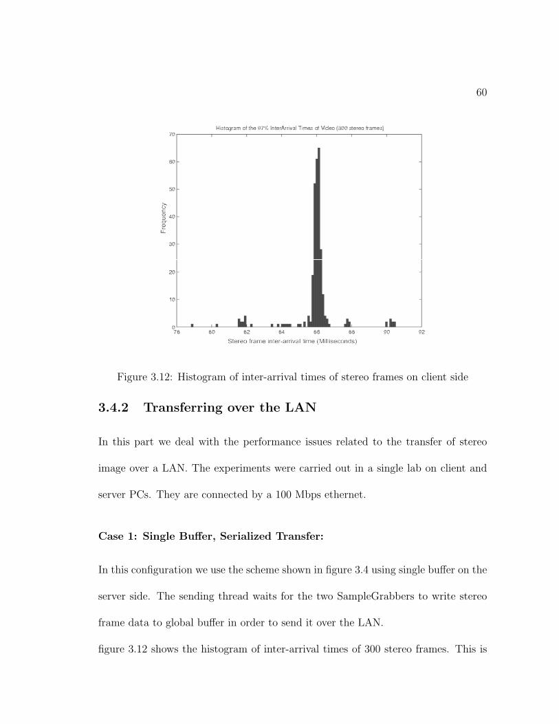
60
Figure 3.12: Histogram of inter-arrival times of stereo frames on client side
3.4.2 Transferring over the LAN
In this part we deal with the performance issues related to the transfer of stereo
image over a LAN. The experiments were carried out in a single lab on client and
server PCs. They are connected by a 100 Mbps ethernet.
Case 1: Single Buffer, Serialized Transfer:
In this configuration we use the scheme shown in figure 3.4 using single buffer on the
server side. The sending thread waits for the two SampleGrabbers to write stereo
frame data to global buffer in order to send it over the LAN.
figure 3.12 shows the histogram of inter-arrival times of 300 stereo frames. This is
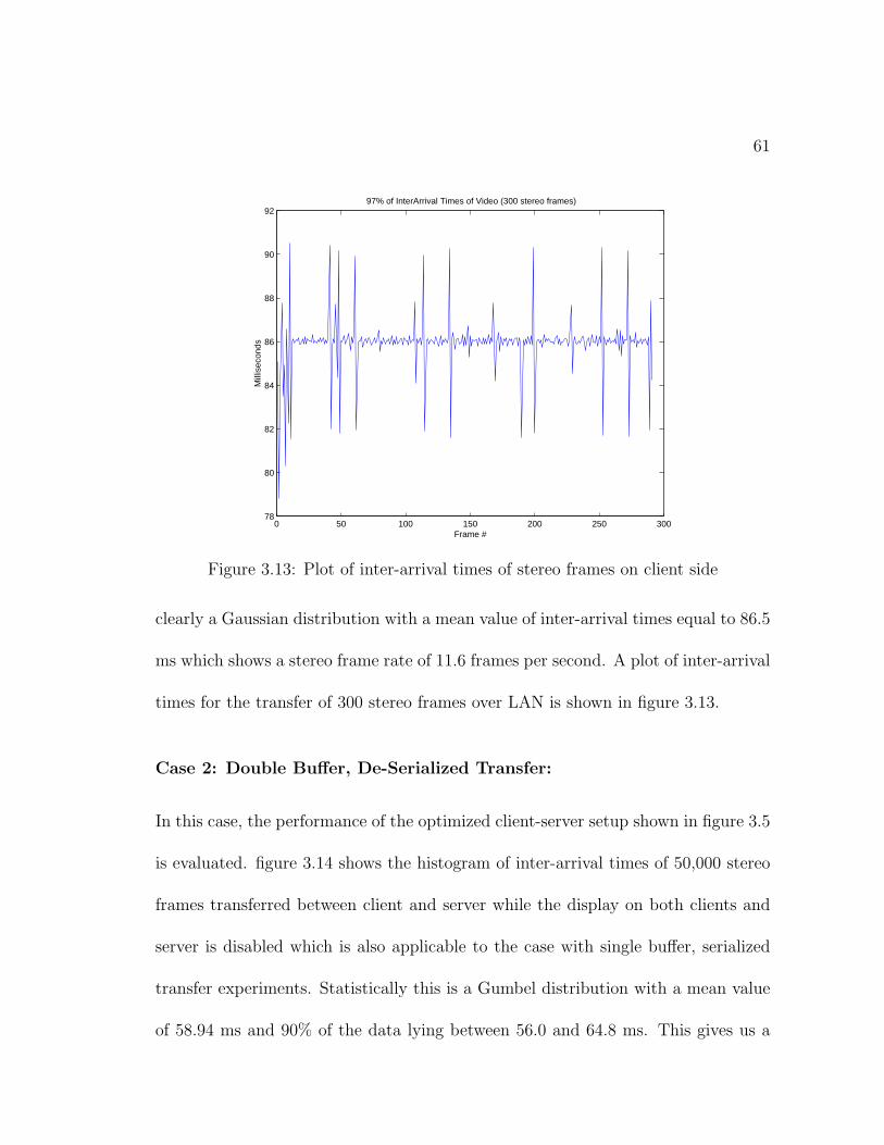
61
0 50 100 150 200 250 30078
80
82
84
86
88
90
9297% of InterArrival Times of Video (300 stereo frames)
Frame #
Mill
isec
onds
Figure 3.13: Plot of inter-arrival times of stereo frames on client side
clearly a Gaussian distribution with a mean value of inter-arrival times equal to 86.5
ms which shows a stereo frame rate of 11.6 frames per second. A plot of inter-arrival
times for the transfer of 300 stereo frames over LAN is shown in figure 3.13.
Case 2: Double Buffer, De-Serialized Transfer:
In this case, the performance of the optimized client-server setup shown in figure 3.5
is evaluated. figure 3.14 shows the histogram of inter-arrival times of 50,000 stereo
frames transferred between client and server while the display on both clients and
server is disabled which is also applicable to the case with single buffer, serialized
transfer experiments. Statistically this is a Gumbel distribution with a mean value
of 58.94 ms and 90% of the data lying between 56.0 and 64.8 ms. This gives us a
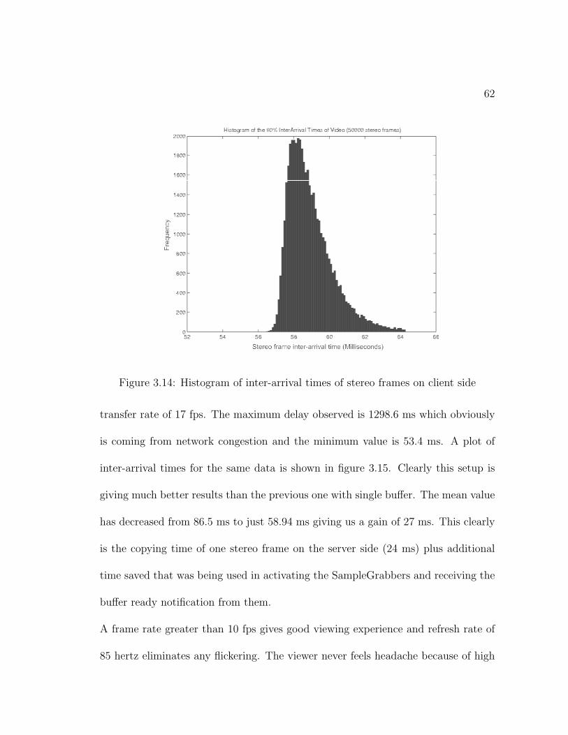
62
Figure 3.14: Histogram of inter-arrival times of stereo frames on client side
transfer rate of 17 fps. The maximum delay observed is 1298.6 ms which obviously
is coming from network congestion and the minimum value is 53.4 ms. A plot of
inter-arrival times for the same data is shown in figure 3.15. Clearly this setup is
giving much better results than the previous one with single buffer. The mean value
has decreased from 86.5 ms to just 58.94 ms giving us a gain of 27 ms. This clearly
is the copying time of one stereo frame on the server side (24 ms) plus additional
time saved that was being used in activating the SampleGrabbers and receiving the
buffer ready notification from them.
A frame rate greater than 10 fps gives good viewing experience and refresh rate of
85 hertz eliminates any flickering. The viewer never feels headache because of high
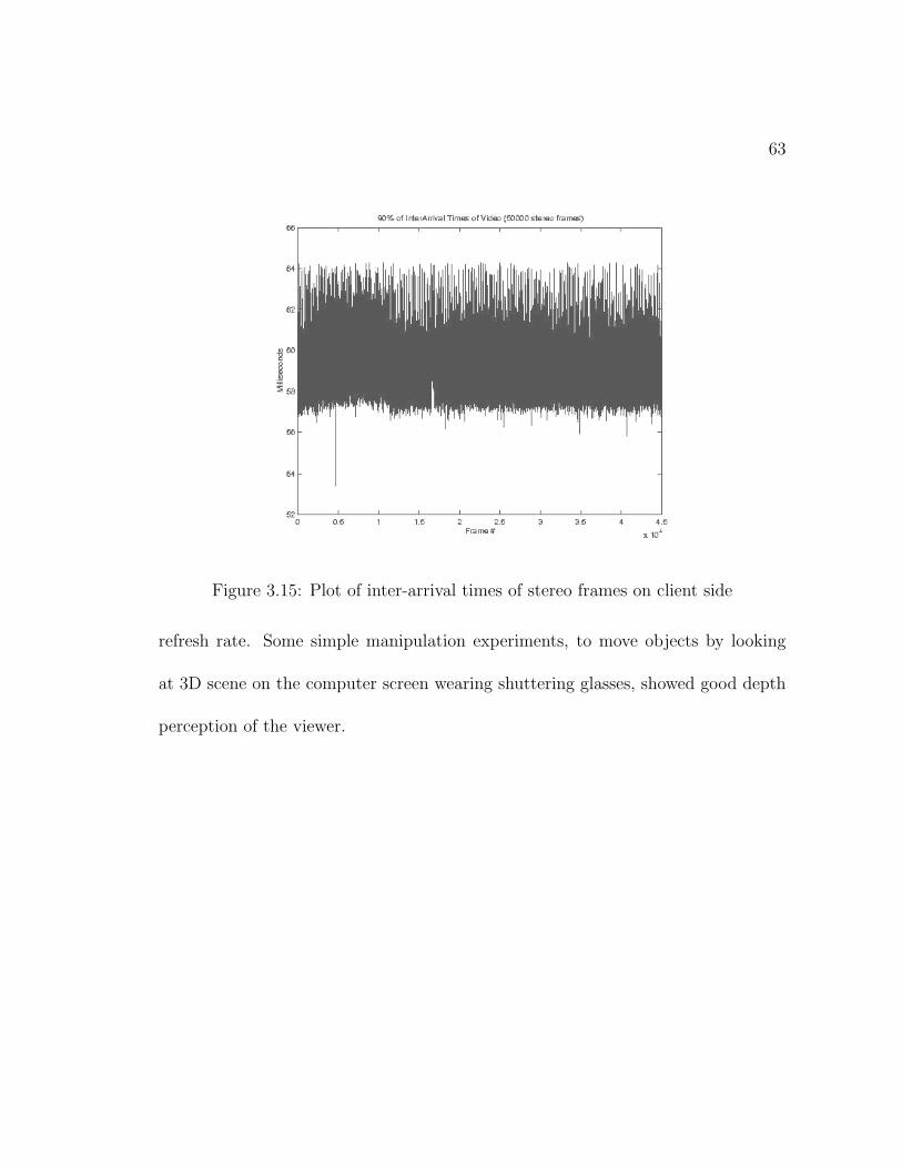
63
Figure 3.15: Plot of inter-arrival times of stereo frames on client side
refresh rate. Some simple manipulation experiments, to move objects by looking
at 3D scene on the computer screen wearing shuttering glasses, showed good depth
perception of the viewer.
Chapter 4
A Multi-threaded Distributed
Telerobotic Framework
A telerobotic system consists of master and slave stations which are usually con-
nected by a computer network. In order to establish a reliable working relationship
between master and slave arms, different schemes are used to convey master com-
mands over to the slave arm. Distributed application programming is one of the
schemes to establish a reliable connection between master and slave arms. Basi-
cally different items are realized as software components and then these components
communicate with each other using distributed application programming paradigm.
This is strictly an object oriented approach and promises all the benefits of ob-
ject oriented programming like software reusability, easy extensibility, less time in
64
65
debugging, data encapsulation, etc.
There are three most dominating distributed object technologies which are given
as 1) CORBA, 2) .NET and, 3) JAVA/RMI. CORBA is an abbreviation for Common
Object Request Broker Architecture and RMI stands for Remote Method Invocation.
These are extensions of traditional object-oriented systems that allow the objects
to be distributed across a heterogeneous network. The objects may reside in their
own address space outside the boundary of an application or on a different computer
than the application and still be referenced as being part of the application.
All of the three distributed object technologies are based on a client/server
approach implemented as network calls being transported on network protocols
like HTTP, TCP/IP, etc. RPC(Remote Procedure Call) is the basic idea behind
the CORBA and RMI technologies. In this approach, the local(client) and re-
mote(server) ends are replaced by stubs thus making possible for both the client
and server to use local calling conventions for remote methods. In order to avoid
the hard and error prone implementations of network calls directly to the client and
server objects, the distributed technology standards address the complex networking
interactions through abstraction layers and hide the networking issues in order to
let the programmer concentrate on developing the core logic of the application.
66
4.1 An Overview of the Distributed Object Tech-
nologies
Here we present a brief overview of the three above mentioned technologies offering
support for distributed programming.
4.1.1 CORBA
CORBA is an open distributed object computing infrastructure standardized by
OMG(Object Management Group) [49]. CORBA is the most widely used middle-
ware standard in the non-Windows market. ORB(Object Reference Broker) is the
core of CORBA architecture. All the CORBA objects interact with each other trans-
parently using ORB regardless of whether these objects are local or remote. IIOP
(Internet Inter-ORB Protocol) was developed in the CORBA 2.0 as a means for the
communication between ORBs from different vendors. IIOP runs on top of TCP/IP.
Every CORBA object must be declared in IDL(Interface Definition Language), a
language to declare the interfaces and methods of a CORBA server object. It is to
be noted that CORBA is just a specification and many different implementations
exist, all conforming to the same specifications.
67
4.1.2 .NET
The .NET architecture by Microsoft has replaced the DCOM, previously used for dis-
tributed computing on, mainly, Windows based machines. In .NET, the COM(Component
Object Model) is replaced by CLR(Common Language Runtime) that supports and
integrates components developed in any programming language conforming to CLR
specifications. .NET is a loosely coupled architecture for distributed applications.
The remote access is based on XML and SOAP(Simple Object Access Protocol)
technologies. It also supports JAVA like object references and garbage collection
but it has no JVM(JAVA Virtual Machine) like interpreter. IL(Intermediate Lan-
guage) code is compiled by JIT(Just-In-Time) compiler to native machine code prior
to execution. Compiled IL code executes on top of a portable API(Application Pro-
gramming Interface) that enables future platform independence.
.NET provides two main strategies to use distributed objects, 1) Web services
and, 2) .NET Remoting. Web services involve allowing applications to exchange
messages in a way that is platform, object model, and programming language in-
dependent. Web services use XML and SOAP to form the link between different
objects. Remoting, on the other side, relies on the existence of the common language
runtime assemblies that contain information about data types. For the closed envi-
ronments where faster connections are required, .NET Remoting is an ideal solution
cutting the overhead caused by object and data serialization through XML.
68
4.1.3 JAVA/RMI
It is a standard developed by JavaSoft. JAVA has grown from a programming lan-
guage to three basic and completely compatible platforms; J2SE(JAVA 2 Standard
Edition), J2EE(JAVA 2 Enterprise Edition) and J2ME(JAVA 2 Micro Edition).
RMI supports remote objects by running on a protocol called the JRMP(JAVA
Remote Method Protocol). Object serialization is heavily used to marshal and un-
marshal objects as streams. Both client and server have to be written in JAVA to
be able to use object serialization. The JAVA server object defines interfaces that
can be used to access the objects outside the current (JVM)JAVA Vitual Machine
from another JVM that could reside on a different computer. A RMI registry on
the server machine holds information of the available server objects and provides
a naming service for RMI. A client acquires a server object reference through the
RMI registry on the server and invokes methods on the server object. The server
objects are named using URLs and the client acquires the server object reference by
specifying the URL.
4.2 Motivation for Using .NET Framework
The system development support for .NET based components in most common
languages like Visual Basic, Visual C++ and C# is excellent when using Microsoft
Visual Studio as an integrated development environment. Components developed in
69
any of the above languages as well as other languages conforming to CLR specifica-
tions, can be used easily in different applications and can interact with components
developed in different languages. JAVA and CORBA support multiple inheritance
while .NET does not. However, multiple inheritance at the interface level is provided
in the .NET framework which compensates for the unavailability of the former. In
comparison to DCOM, .NET provides object and data serialization through a fire-
wall making it more dependable on even the internet. In addition, there is no need
for component registration on the server side. The application just requires an ac-
cess to server assembly which contains the implementation of server objects as well
as the meta-data for these objects.
.NET components are self-describing: type signatures and other information
is embedded in the components. This allows a lot of reflection on types, and it
makes it possible for services such as the Visual Studio debugger to work across
different languages. This level of debugging for components developed using different
languages and in one environment is still missing in CORBA and JAVA. Microsoft
technologies are a very good choice for organizations that mainly use Windows OS
to run mission-critical applications [50]. In our case, we need a real-time distributed
system that will run on two lab PCs with Windows 2000 and commodity 100 Mbps
LAN. .NET based distributed components prove to be an excellent choice for the
proposed framework.
70
By using the distributed programming, network protocol issues can be avoided in
the sense that the distributed framework itself takes care of all the network resources
and data transfer over the network. In other words, distributed components based
approach gives us complete isolation from network protocols. The framework can
decide either to use TCP or HTTP protocols. All of the components are created
using Visual C# as programming language.
In order to describe the complete system, we need to explain individual com-
ponents and their interactions with each other when they co-exist in a distributed
application. For simplicity we can divide the components in two groups, i.e., server
side components and client side components.
4.3 Server Side Components
On the server side, we have the following components;
1. PUMA Component
2. Force Sensor Component
3. Decision Server Component
In addition to these components, we also have some interfaces known as;
1. Proxy Robot Interface
71
2. Force Sensor Interface
3. Decision Server Interface
The details of the functionalities of these components and interfaces will be discussed
in the following pages. First we start with the components.
4.3.1 PUMA Component
PUMA component is the heart of the distributed framework as this deals with the
commands being sent to robot and the response of the robot. This component
acts as a software proxy of the robot. In other words commands are issued to the
component as they are issued to the robot and whenever the robot changes its states,
the component updates itself automatically to reflet these changes. A block diagram
of the PUMA component is shown in figure 4.1. At the center of this component is
PUMA control which is basically a user control and exposes different public methods
and public properties. Some of the public methods exposed by PUMA component
are;
• public bool ConnectRobot()
• public bool InitializeRobot()
• public bool InitializeRobot(double[] jointSpaceVars);
• public bool MoveIncremental(double[] incJointAngles)
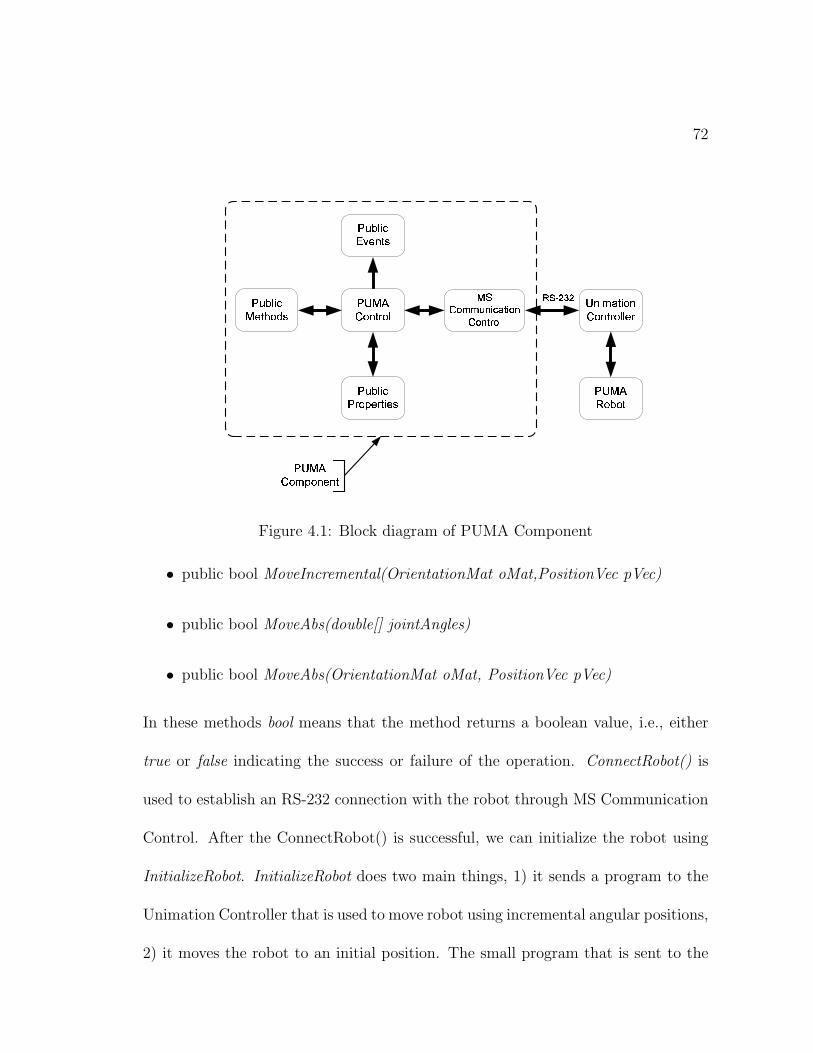
72
��������������
�� � ����� � � � � �� � �� � ��
����������� �!#" $&%#' " ��!
����!(' ) ��*
�+������ � �� � �,�
��-�� � .�/��� 0��1�2
�+-�� � .��� �3��� � � ��2
�+-�� � .4,5��, �� 2
67�8 9#: 9
�������� ��;3� �� ��
Figure 4.1: Block diagram of PUMA Component
• public bool MoveIncremental(OrientationMat oMat,PositionVec pVec)
• public bool MoveAbs(double[] jointAngles)
• public bool MoveAbs(OrientationMat oMat, PositionVec pVec)
In these methods bool means that the method returns a boolean value, i.e., either
true or false indicating the success or failure of the operation. ConnectRobot() is
used to establish an RS-232 connection with the robot through MS Communication
Control. After the ConnectRobot() is successful, we can initialize the robot using
InitializeRobot. InitializeRobot does two main things, 1) it sends a program to the
Unimation Controller that is used to move robot using incremental angular positions,
2) it moves the robot to an initial position. The small program that is sent to the
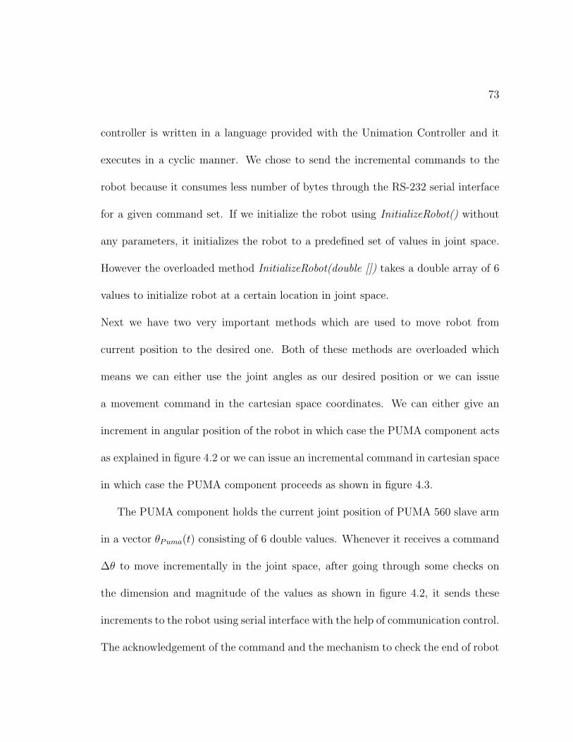
73
controller is written in a language provided with the Unimation Controller and it
executes in a cyclic manner. We chose to send the incremental commands to the
robot because it consumes less number of bytes through the RS-232 serial interface
for a given command set. If we initialize the robot using InitializeRobot() without
any parameters, it initializes the robot to a predefined set of values in joint space.
However the overloaded method InitializeRobot(double []) takes a double array of 6
values to initialize robot at a certain location in joint space.
Next we have two very important methods which are used to move robot from
current position to the desired one. Both of these methods are overloaded which
means we can either use the joint angles as our desired position or we can issue
a movement command in the cartesian space coordinates. We can either give an
increment in angular position of the robot in which case the PUMA component acts
as explained in figure 4.2 or we can issue an incremental command in cartesian space
in which case the PUMA component proceeds as shown in figure 4.3.
The PUMA component holds the current joint position of PUMA 560 slave arm
in a vector θPuma(t) consisting of 6 double values. Whenever it receives a command
∆θ to move incrementally in the joint space, after going through some checks on
the dimension and magnitude of the values as shown in figure 4.2, it sends these
increments to the robot using serial interface with the help of communication control.
The acknowledgement of the command and the mechanism to check the end of robot
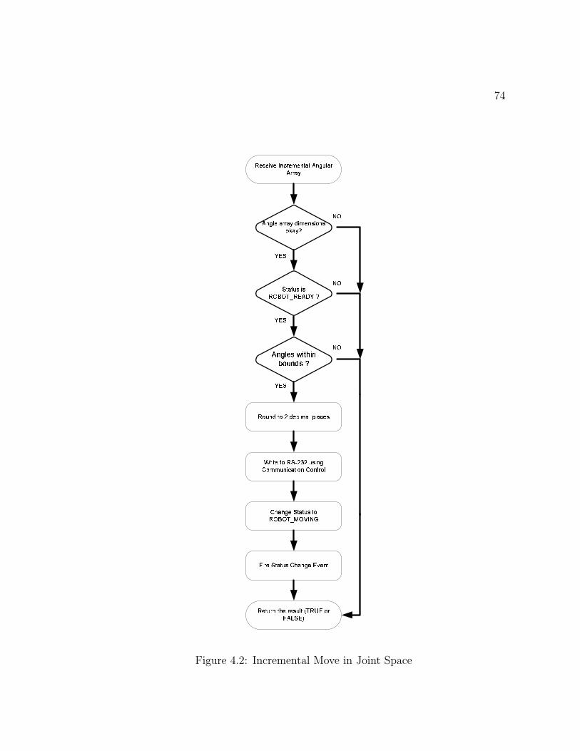
74
��� � � � � ��� � � � �� � � � ��� � � � �� �
� � � � ��� � �� � � � � � � � ������� � ��� ���
!#" $�% & '#(*) + ,�) "- .�/�" 0�'21
� � � � 3�� �54�3 � � � � � 6 � � � �
78 � � ��� ����� 9 4 : 4;� � � � �<�� 55� � � � � � � �5<�� � � � �
<�� � � �;� � � � ��� ���=�> =�� ? @5=�A�� B�C
� � �5� � � � ��<�� � � ��� � � � �
B�=
D�� �
��� � � �; ��3 � �� � � � � � �� E � F
� � � � ��� ���=�> =�� ?���� ��G D8F
D�� �
B�=
B�=
D�� �
Figure 4.2: Incremental Move in Joint Space
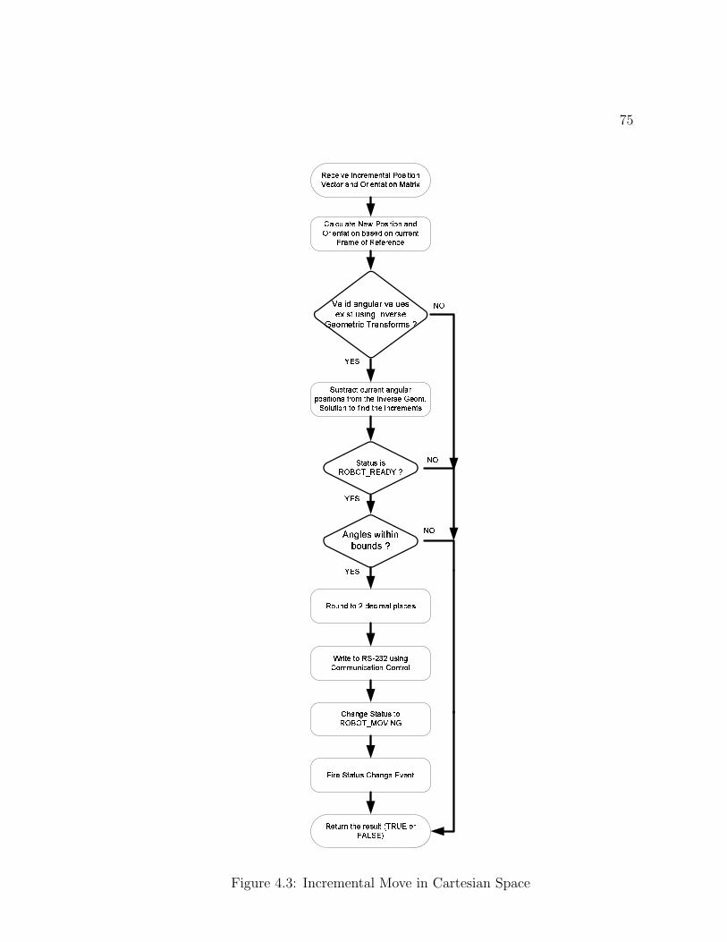
75
� � � � � � ��� � � � � � � � � � � � � � � � ���� � � � � � � ����� � � � � � � � � ����� � � � �
� � � � � ��� � ��� � � � � � � ���� �� �! "$# %� &
')( *+ , -�.0/ 1 2�/ (3 4�5�( 6�-87
� � � � �� �9�� � � � �� : � � � �
;8� � � �� ����% < 9 = 9�� � � � >?�� �� � � � � � � � ��?�� � � � �
?$� � � > ��% � � � � �$� ����@ �$� A ���$��� B�C
! � � ��% � � � � �?�� � � > �) � � � �
B��
D$ %
E�F G H I)F J K L G F M N F G L O PO Q H P R�L P H J KTS J N O M P O
U�O V W�O R M H X�Y�M F J P Z V M W)P�[
% � � � � ��� �����@ �$� A��$ "$\ D^]
D$ %
B��
B��
D$ %
?$� � � � � ��B � _`� � � � � � � ��� � ���� � � � � � � � � �a � � � �� ��� � � � � � �
! � � ���� b ��� b � � � � � �
%�� a � � � � � � � � � � � � � � > � � �: � � � � � � � ��b � � c� � ��� � � � � � ��C�� � �d% � � � � � ��� ��b � � �� � ��� � � � � �� � � �
Figure 4.3: Incremental Move in Cartesian Space
76
movement will be discussed shortly.
In the overloaded form, MoveIncremental takes two parameters as input. 1) ∆X and
2) ∆M , where ∆X holds the increments in position vector and ∆M is the change in
the orientation matrix of the slave arm. At any time t, PUMA component holds a
copy of current position vector X(t), a (3×1) vector, and current orientation matrix
M(t), a (3 × 3) matrix. The new position vector Xnew(t) and orientation matrix
Mnew(t) are calculated from {X(t),M(t)} and {∆X,∆M} taking into consideration
the current frame of reference. Current frame of reference can be of any one of the
following three values;
1. BASE FRAME
2. WRIST FRAME
3. TOOL FRAME
Once Xnew(t) and Mnew(t) are calculated, we use the Inverse Kinematic Model
G−1(Xnew,Mnew) of the PUMA robot that is embedded in PUMA component to
find the joint space variables θnew. G(θ) denotes the Direct Kinematic Model which
gives us the position and orientation matrices {X,M} from the joint space variables
θ. After we have the θnew, PUMA component checks whether we have valid results
from the Inverse Model or not. If the results are valid then current joint space values
θ(t) are subtracted from these values i.e., θnew to find ∆θ. These incremental values
77
are then sent to the program running on the Unimation Controller. This whole
process is elaborated in figure 4.3.
If it is required to move the robot to a specified position by supplying the absolute
values of either joint space variables i.e., θrequired or a certain position vector and
orientation matrix i.e., {Xrequired,Mrequired}, this is possible by using the overloaded
public method MoveAbs exposed by the PUMA component. In the first instance
MoveAbs takes an array of 6 double values as θrequired, subtracts the current joint
space variables θ(t) from this, and sends the resulting ∆θ to the robot. In the
second overloaded instance, 1) it takes two parameters namely {Xrequired,Mrequired},
2) evaluates the Inverse Kinematic Model, 3) finds the difference between required
angular positions and the current θ(t) and 4) sends the difference to the robot.
Using the above described public methods it is very easy to program the robot and
interface it with any of the input devices such as master arm, joystick, keypad,
mouse etc. These versatile commands to move the robot give us the flexibility to
map the Controller to virtually any possible control scheme giving control signals
as increments or absolute positions, in joint space or cartesian space.
The PUMA component also makes available some public properties to set or retrieve
the attributes of the robot in realtime. The major properties that it exposes are
listed below;
1. Correction Values of Robot Angles
78
2. Current Orientation Matrix of the Robot
3. Current Position Vector of the Robot
4. Current Joint Angles
5. RS-232 Communication Settings
6. Current Working Frame Mode of the Robot
7. Current Status of the Robot
The first property sets or gets the correction values of robot angles. We need these
correction values to set the reference points for all 6 angles in the joint space. Second,
third and fourth properties provide us with the information regarding the current
position of the robot both in joint as well as cartesian space. All of these values are
readonly. Then we have Communication Settings property to set the communication
port settings for RS-232 link. We can get and set the current working frame mode
of the robot using property no. 6. The last property is again readonly and with the
help of this property we can find out the current status of the robot. The status of
the robot can be any one of the following;
ROBOT NOT CONNECTED: Connection to Robot is not detected or Robot
not initialized
ROBOT CONNECTED: Robot is connected but not initialized
79
ROBOT WAIT STAT: Robot is in between some initilization process
ROBOT READY: Robot is ready to accept move commands
ROBOT MOVING: Robot is currentrly moving
ROBOT ERROR: Some error occurred, you may want to initialize again
In addition to the methods and properties, the PUMA component also fires events
that we can use to keep an eye on different occurrings related to the robot. The
events invoked by PUMA component include;
PUMADataReceived Event: Data received from PUMA through serial interface
PUMAErrorOccured Event: Some error occurred with PUMA
PUMARobotMoved Event: Robot moved to a new location
PUMAStatusChanged Event: PUMA status changed
The program using the PUMA component can attach its own event handlers to
these events to take certain actions when the respective events are invoked by the
PUMA component.
4.3.2 Force Sensor Component
This component takes care of the force sensing operation carried out on the server
side. The force sensing operation is done in a separate thread on the server, the
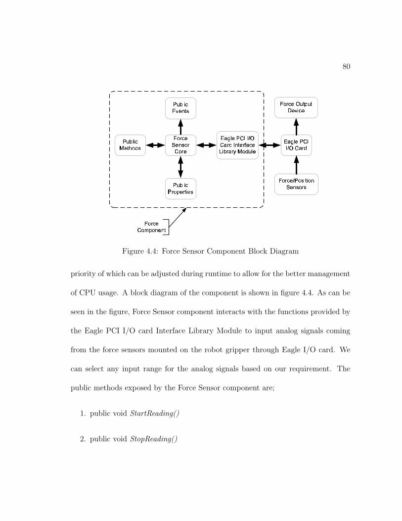
80
����� ���� ���� � ���� �������� �
������� ������� � ������� �
������� � !����� � ��"��� ��� �#� ��� $ �����%� &�� ��� ')(*����+�� �
����� ���� ������������� �
�+&�� �()��� ,�����
!+&�� �!� ��-��� � ���
!+&�� ���.���#� �
����� ����"��/)-�������
����� ��� �0+#� -�+#�1"�#.� ���
Figure 4.4: Force Sensor Component Block Diagram
priority of which can be adjusted during runtime to allow for the better management
of CPU usage. A block diagram of the component is shown in figure 4.4. As can be
seen in the figure, Force Sensor component interacts with the functions provided by
the Eagle PCI I/O card Interface Library Module to input analog signals coming
from the force sensors mounted on the robot gripper through Eagle I/O card. We
can select any input range for the analog signals based on our requirement. The
public methods exposed by the Force Sensor component are;
1. public void StartReading()
2. public void StopReading()
81
When a new instance of the Force Sensor component is created, it initializes a new
thread with a default normal priority and waits until the sensing is triggered with
StartReading() function. After the reading has started, it continues sensing the
force information from the sensors at a pre-specified default frequency. Each time
it samples the 6 force sensors through its AD (Analog to Digital) input channels,
it prepares a double array of 6 values and invokes an event to inform the parent
application of the availability of another force packet. The parent application can
respond to this event using some event handler at the higher level of application
hierarchy. The event itself carries the force information so we do not have to access
some global memory for the transfer of force data. Similarly the component also
provides StopReading() function to abort the force sensing thread anytime we want.
This will free the CPU of the load of the force thread and all events coming from the
Force Component will stop. After the force thread is stopped, we can again trigger
the force sensing using StartReading().
The Force Sensor component also exhibits the following public properties;
1. SensorThreadPriority
2. TimerValue
3. ThresholdValue
The SensorThreadPriority property can be used to set the thread priority of the
force sensing thread. The thread priority can be one of the five values provided by
82
the operating system ranging from BelowNormal to Highest. The Highest priority
does not guarantee that it will be a non-preemptive thread because of the operating
system constraints. TimerValue can be used to set a time interval between two
successive readings of the force sensors. In other words, we can set the frequency of
the force sampling using this property. ThresholdValue is helpful in situations when
we need the force event to be invoked only when a considerable change in any of the
force sensor values occurs. We can set the ThresholdValue property in accordance
with the minimum change that we want to notice. Anything below this will be
ignored by the Force Sensor component and no event will be fired. Alternatively
this can be set to zero to monitor any possible change in sensor outputs.
4.3.3 Decision Server Component
DecisionServer is, in true sense, a derived component from both PUMA and Force
Sensor components. We need the presence of a component having the capabilities
of both the PUMA and Force Sensor components in order to close an autonomous
loop on the server side for possible extensions of the telerobotic system to incor-
porate a supervisory and/or a learning mode telerobotic control. Also in order to
effectively use the public methods and properties of PUMA and Force Sensor com-
ponents remotely, we need to implement an interface that will be referenced from
the remote clients in order to realize a truly distributed telerobotic system. Simply
83
put, DecisionServer is a higher abstraction layer present on the server side. The
presence of this layer allows us to issue commands to the robot and force sensors
and take feedback from the same at a higher level. Another advantage of this layer is
the implementation of different modifiers to the commands coming from the client,
for example workspace scalability function can be implemented on this level. If a
learning mode is implemented in the future, DecisionServer can serve as an agent
that will record the trajectories and will repeat them by realizing an impedance
control with the help of PUMA and Force Sensor components. A block diagram
explaining the role of DecisionServer in the hierarchy of the system on server side is
shown in figure 4.5. It is clear from the figure that server side logic is implemented
in four layers. The last layer in the hierarchy is the physical layer consisting of robot
and force sensors. On the highest level of the hierarchy is the human operator that
might interact with the system using a UI(user interface). A possible autonomous
local loop on the server side can be constructed in the lower three layers. This can
help automate the execution of simpler tasks in the presence of large time delays.
4.3.4 Server Side Interfaces and .NET Remoting
An interface is a set carrying definitions of public methods and properties. It servers
as a contract for any component that implements this interface. In other words, any
component that inherits or implements the definitions contained in an interface,
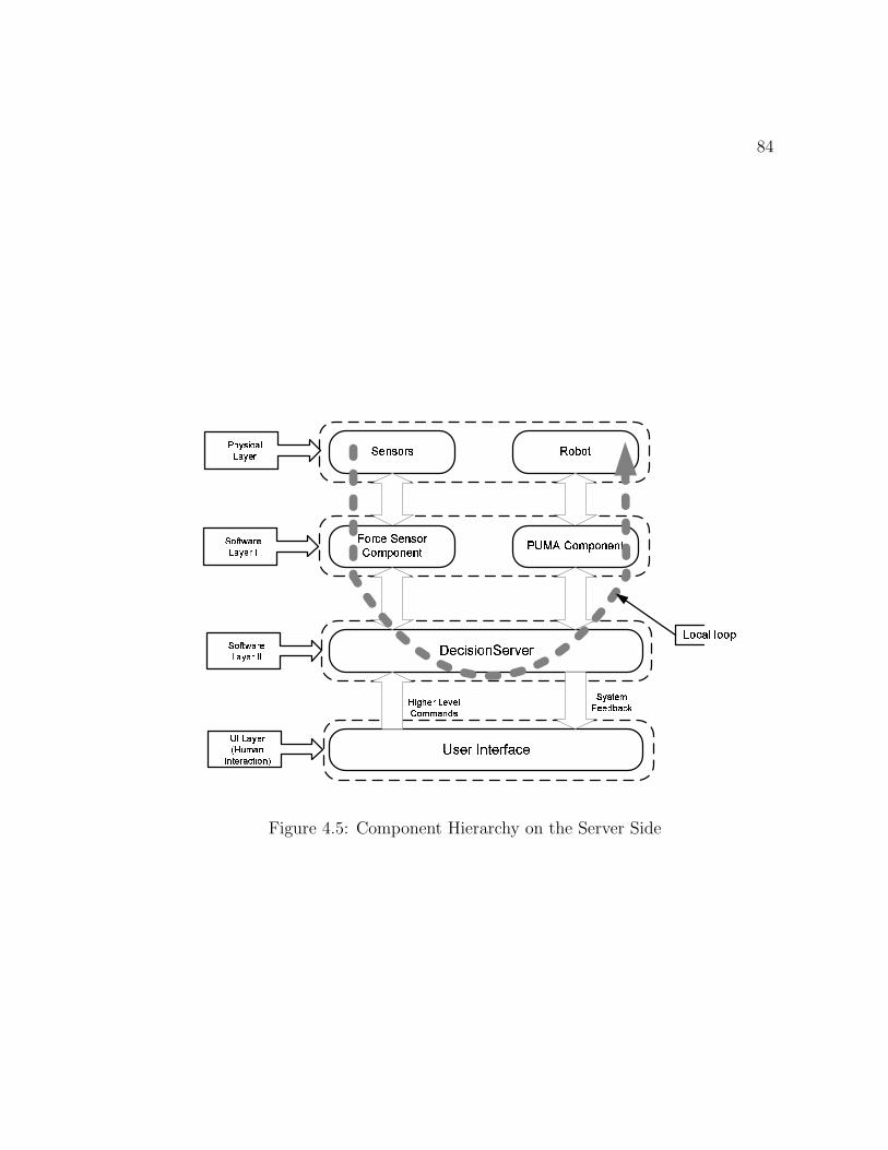
84
����� � ��� � ��� � �
���� � ������� � ���������� ��� ��� � ������� ���������� ��� �
��� ��! "�! # $�%&� ' ()��'
*�"���'�+ $�, ��' - .����
/�0 1 2 3 4 5 3 6 3 78�9 :�:�; < = >
? @ > A 3 :B 3 3 = C ; D E
F 2 @ > 0 D ; 75 ; @ 3 4
? 9 G A H�; 4 35 ; @ 3 4 I
? 9 G A H�; 4 35 ; @ 3 4 I I
J�I 5 ; @ 3 4K /�L :); <I < A 3 4 ; D A 0 9 < M
N ��� O�P P �����
Figure 4.5: Component Hierarchy on the Server Side
85
must provide the implementation of all the methods or properties enumerated in
the interface. This scheme is needed in .NET based distributed applications be-
cause any client that accesses or executes the methods of a component on the server
needs an access to the server assembly or component. By giving a reference to an
interface that the server component implements, we can hide the actual component
or assembly from the client. This provides security from potential unsafe clients
as well as gives the developers freedom to the easily amend the logic of the server
methods while the interface remains unchanged for all the clients because an inter-
face is only a definition, the implementation being only inside the component.
In order to attain references to both the PUMA and Force Sensor components, we
define two interface named IProxyRobot and IForceSensor. These interfaces carry
the definitions of public methods, properties and events of PUMA and Force Sen-
sor components as explained in sections 4.3.1 and 4.3.2. Further we define another
interface IDecisionServer which inherits both the IProxyRobot and IForceSensor in-
terfaces. By this approach we are able to define a unified set of public members
(methods, properties and events) that are required to be implemented in the form
of DecisionServer component on the server side.
Once IDecisionServer is fully implemented, .NET Remoting can be used to publish
an instance of DecisionServer component on the LAN. This instance is identified
by the potential clients by a unique object identifier issued by .NET Remoting.
86
Any client can get a reference to this instance through an IDecisionServer interface.
.NET Remoting enables us to access objects using SOAP(Simple Object Access
Protocol). This scheme isolates the network protocol issues from the software devel-
opment of a distributed application. Any object/component that might be located
on the other end of the world can be referenced using this distributed scheme as if
it was available on the same machine.
4.4 Client Side Components
The client side in this distributed environment contains the IDecisionServer inter-
face, to reference the server side component through .NET Remoting, as well as Mas-
terArm component. In addition to these, there is an instance of client GUI(Graphic
User Interface).
4.4.1 Decision Server Interface
Decision Server interface named as IDecisionServer contains all the definitions to
execute methods on PUMA and Force Sensor components. With the help of this
interface we can also get or set the public properties of the above mentioned two
components located on the server side. In the beginning, after the client side program
is initialized, it carries only an un-referenced interface to DecisionServer component.
Once a network connection with the server is established, the client gets the reference
87
to the server side instance of DecisionServer. Now IDecisionServer refers to the
published instance of DecisionServer and the client side can access the server side
instance of DecisionServer as a local component through IDecisionServer.
4.4.2 MasterArm Component
This component implements all the functionality required to interact with a force
feedback master arm. The MasterArm component, after initialization, has active
instances of two force components, one each for reading and writing in different
threads. It also implements the local force feedback to help the operator by reducing
the amount of force required to manipulate the master arm. The local force feedback
uses a second order model for minimizing the mechanical impedance of the master
arm. In order to estimate the force feedback, the component maintains a record
of all the force data read for a certain number of samples(history) along with the
record of the system time. Then it evaluates the velocity and acceleration of the
master arm at each sampling instant. This information is used to calculate the force
proportional to what the operator is applying which is then fed back to the master
arm.
The motivation for injecting this force back to the master arm comes from the
following expression describing the relationship between the torque applied and the
88
angular displacement of the master arm:
Γ = Jθ + dθ (4.1)
where Γ is the applied torque, J is mass moment of inertia, d is damping coefficient
and θ is the angular displacement. If we re-inject a force f given as:
f = βθ + αθ (4.2)
the mechanical impedance of the master arm reduces because of the reduced amount
of torque applied by the operator for a given angular displacement. The new value
of the torque Γ is given by:
Γnew = (J − β)θ + (d− α)θ (4.3)
where α and β are coefficients of angular velocity and acceleration respectively.
Suppose the position of the master arm at an instant t1 is x. Then the velocity at
an interval t is given by dx/dt = v while the acceleration a is d2x/dt2. The feedback
force f being fed to the master arm is then given by:
f = αv + βa (4.4)
The values of the parameters α and β can be found experimentally so that the
operator feels that the master arm is really helping him in moving it. A functional
block diagram of the MasterArm component is given in figure 4.6. There are two
major inputs to the MasterArm component, 1) position data being read from the
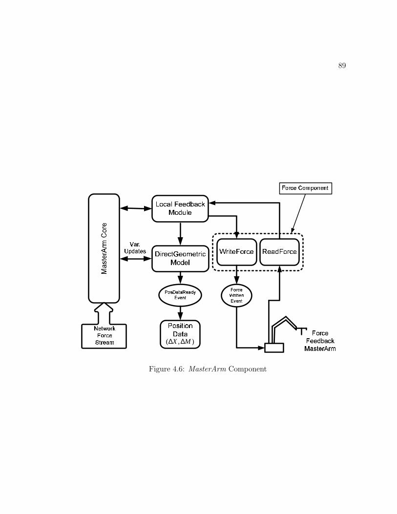
89
����������� ��� � � � ����� ���
������������������������������� �
��� ���� ������� ��� � ����������
! " # $ % & % ')( % * +, - ( . &
/���0�� � � �1����� �
),( MX ∆∆
2�3�4 56�7 8�3 9 : ;
<�=�> ?)@<�@A@�B�C�DA?�EFGDAH I @�> JK> L
M " N O (PQN R & & ( ., - ( . &
ST U VKW�X YZ�W�X [ T\�U X T)]�^
Z�W�X [ T`_�W�^`a W�b)T�b U
Figure 4.6: MasterArm Component
90
master arm and 2) the network stream of force data coming from the remote side.
MasterArm uses the ReadForce module of Force component to read the position
data from master arm joints. The outputs of MasterArm carry 1) the incremental
position data (∆X,∆M) to be sent to the slave arm and 2) the local feedback force
data to be output to master arm.
This is a multi-threaded component that can read and write data simultaneously
as well as process lengthy operation in worker threads. The MasterArm component
also invokes events when 1) a fresh copy of position data (incremental cartesian
position data) is available from ReadForce and 2) when some force data is written
to the master arm.
Some of the public methods revealed by MasterArm are given below:
bool StartReading() : Starts reading the position data from the master arm.
Inherited from Force component.
bool StopReading() : Stops reading the position data from the master arm. In-
herited from Force component.
bool WriteForceData(double[] forceData) : Writes the given force data (force-
Data) to the master arm in a separate thread.
The public properties are as under:
IncOrMatrix : Provides the change in orientation matrix after the position data
91
ready event is fired.
IncPosVector : Provides the incremental position vector after the position data
ready event is fired.
MasterArmEngaged : A boolean property that can be used to find/set whether
a master arm is engaged or not. If this property is false, the direct geometric
model will not be evaluated to save thread time.
ProvideForceFeedback : Again a get/set boolean property indicating whether to
provide force feedback to the master arm or not. This feedback is the force
stream coming from remote side.
VelocityGain : To get/set the velocity gain α.
AccelerationGain : To get/set the acceleration gain β.
ProvideLocalImpedance : A get/set boolean property indicating whether to pro-
vide local impedance to the master arm or not.
4.5 Integrated Scheme of Client-Server Compo-
nents
The integrated scheme incorporating all the components on client and server side
is shown in figures 4.7 and 4.8. We can see that the DecisionServer is inherited
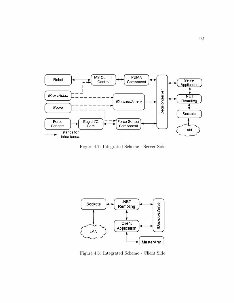
92
�������������� ��� � ���
��� � ������ ����� � �
��� ����� ��� � ���� �!�� ��� ���
� � � �����"� ����� ���� �!�� ��� ���
#�$�% � �'& ( )��$ � *
+ ,.- /10�2�34/�5�/ 6+ 748�91: ;1: / <�=>8 - ?@8�-
+ A�/�- 9�8
B�C�D E�C DF4G�G�H I J�K�L I M N
O P�Q�RS C T M�L I N�U
B M�J�V C L W
X1F PW1L K N�Y�W[Z M DI N \ C D I L K�N�J C O
Figure 4.7: Integrated Scheme - Server Side
��� � ������� � � � ��� � ���
� ������ ������� � �������������� �
�
!#"�$�% &�' (�' )
Figure 4.8: Integrated Scheme - Client Side
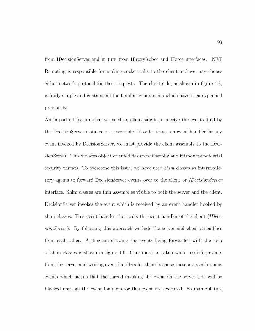
93
from IDecisionServer and in turn from IProxyRobot and IForce interfaces. .NET
Remoting is responsible for making socket calls to the client and we may choose
either network protocol for these requests. The client side, as shown in figure 4.8,
is fairly simple and contains all the familiar components which have been explained
previously.
An important feature that we need on client side is to receive the events fired by
the DecisionServer instance on server side. In order to use an event handler for any
event invoked by DecisionServer, we must provide the client assembly to the Deci-
sionServer. This violates object oriented design philosophy and introduces potential
security threats. To overcome this issue, we have used shim classes as intermedia-
tory agents to forward DecisionServer events over to the client or IDecisionServer
interface. Shim classes are thin assemblies visible to both the server and the client.
DecisionServer invokes the event which is received by an event handler hooked by
shim classes. This event handler then calls the event handler of the client (IDeci-
sionServer). By following this approach we hide the server and client assemblies
from each other. A diagram showing the events being forwarded with the help
of shim classes is shown in figure 4.9. Care must be taken while receiving events
from the server and writing event handlers for them because these are synchronous
events which means that the thread invoking the event on the server side will be
blocked until all the event handlers for this event are executed. So manipulating
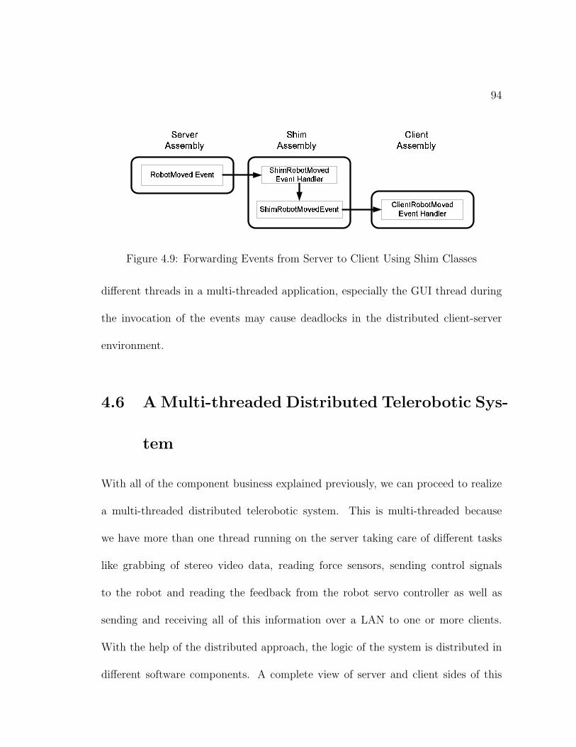
94
����� ������� ���� �� �
��� � �������� ���� �� �
����� ���� ���� �� �
����� � �!#"�! $ %&! ' ( )*�' (�+ $�,�-#+ )�. (#/ �!#" ! $ %&! ' ( )�*�' (#+ $
����� �0 �!#" ! $ %0! ' ( )�*�' (#+ $ 1 . � (#+ $ �!#"�! $ %&!�' (�)*�' (#+ $�,�-#+ )�. (#/
Figure 4.9: Forwarding Events from Server to Client Using Shim Classes
different threads in a multi-threaded application, especially the GUI thread during
the invocation of the events may cause deadlocks in the distributed client-server
environment.
4.6 A Multi-threaded Distributed Telerobotic Sys-
tem
With all of the component business explained previously, we can proceed to realize
a multi-threaded distributed telerobotic system. This is multi-threaded because
we have more than one thread running on the server taking care of different tasks
like grabbing of stereo video data, reading force sensors, sending control signals
to the robot and reading the feedback from the robot servo controller as well as
sending and receiving all of this information over a LAN to one or more clients.
With the help of the distributed approach, the logic of the system is distributed in
different software components. A complete view of server and client sides of this
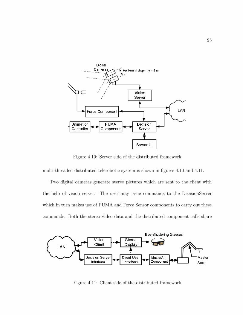
95
���������
�� �� ��� ���� �����
�����
� ��� � �� ��� ���� �����
���� ��������
� ��� � ��!#"���� � ���
� ��� !%$�� � ��� ����� � ��& & ���
'�� � ���# ��!#"���� � ���
(�) *�) + ,�-. ,�/0�1 ,�2 3�465 7 8 4�9 : ;�< =�7 >@? ;65 7 : A�BDCDE F
Figure 4.10: Server side of the distributed framework
multi-threaded distributed telerobotic system is shown in figures 4.10 and 4.11.
Two digital cameras generate stereo pictures which are sent to the client with
the help of vision server. The user may issue commands to the DecisionServer
which in turn makes use of PUMA and Force Sensor components to carry out these
commands. Both the stereo video data and the distributed component calls share
�����
��� �� �� �� � �����
������� ��� ������� !"� # ��$ �� % &��'�
(*) � ���"$�+,�'�� # �'$ � % &��'�
-�.'/ 0 1�2 3�2 45�6 487 6�9 1 9 0
:�&��'$ � ;< =
> � ��? ��@8� �A � B�C
D�E"F�G H,I�J�K K FL M N�OQP8R S�T'T'FT
Figure 4.11: Client side of the distributed framework
96
the same LAN, however they open different TCP connections for the data transfer.
The client side uses the GUI as well as master arm to issue commands to the slave
arm on remote side. The vision client receives the synchronized stereo data from
the LAN through windows sockets and provides a stereo display of the remote scene
to the viewer using eye-shuttering glasses. Head mounted display can also be used.
A view of the client GUI is shown in figure 4.12.
4.7 Performance Evaluation
The objective of performance evaluation is to study the streaming of video, force
and commands flowing through the LAN, their effect on each other, and maximum
possible refresh rate for each. This is critical to assess Q.o.S. of the above mentioned
streaming and its operating conditions which is useful to evaluate overall quality of
remote sensing and global teleoperation loop.
Performance evaluation experiments were carried out on the distributed frame-
work described in section 4.6. The bandwidth of the LAN is 100 Mbps and both
the client and server PC are located in a single lab. The client and server are 2.0
GHZ P-IV machines with 1 GB DRAM. The client side video display card, which is
used to display realtime stereo video data, is an accelerated graphics card with 256
MB DDR memory. Each force data packet contains 6 double values , which equal
6× 8 = 48 bytes.
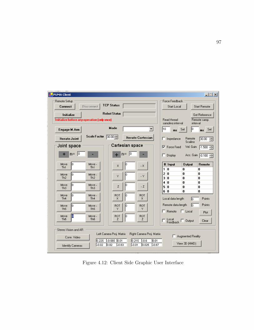
97
Figure 4.12: Client Side Graphic User Interface
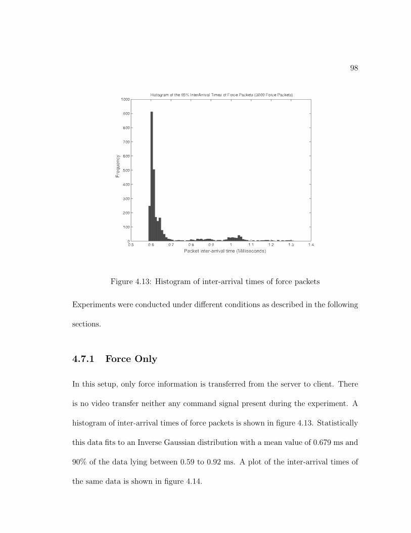
98
Figure 4.13: Histogram of inter-arrival times of force packets
Experiments were conducted under different conditions as described in the following
sections.
4.7.1 Force Only
In this setup, only force information is transferred from the server to client. There
is no video transfer neither any command signal present during the experiment. A
histogram of inter-arrival times of force packets is shown in figure 4.13. Statistically
this data fits to an Inverse Gaussian distribution with a mean value of 0.679 ms and
90% of the data lying between 0.59 to 0.92 ms. A plot of the inter-arrival times of
the same data is shown in figure 4.14.
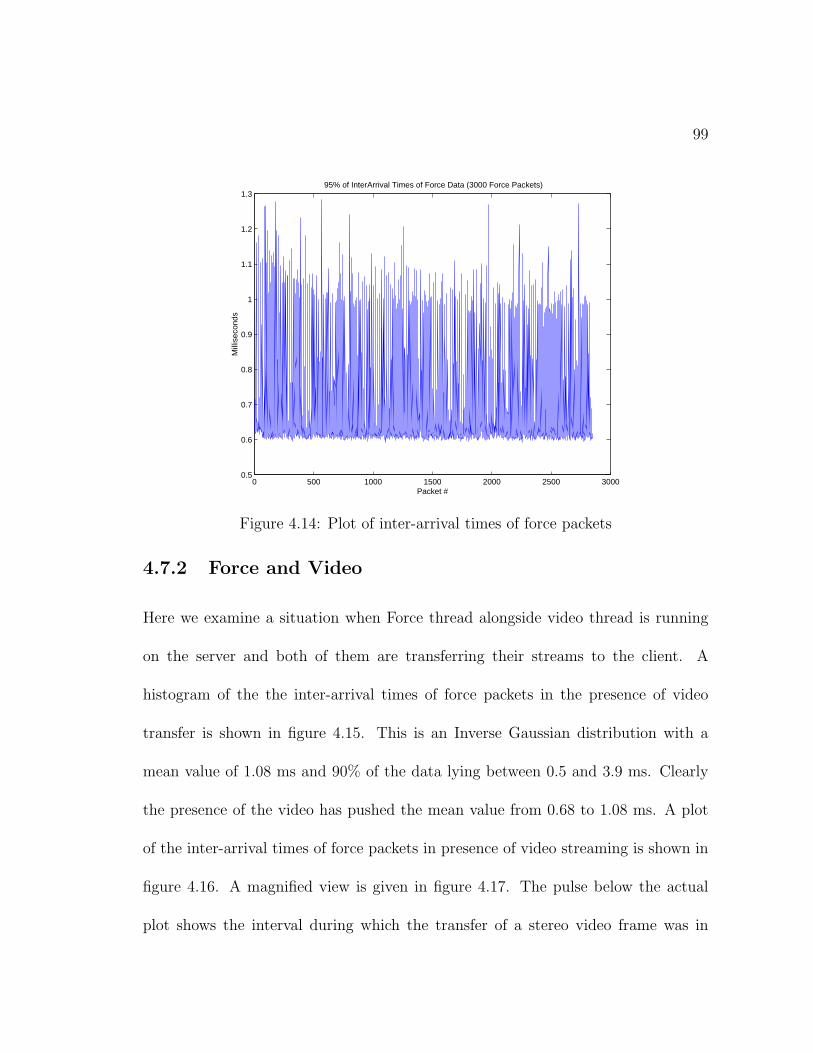
99
0 500 1000 1500 2000 2500 30000.5
0.6
0.7
0.8
0.9
1
1.1
1.2
1.395% of InterArrival Times of Force Data (3000 Force Packets)
Packet #
Mill
isec
onds
Figure 4.14: Plot of inter-arrival times of force packets
4.7.2 Force and Video
Here we examine a situation when Force thread alongside video thread is running
on the server and both of them are transferring their streams to the client. A
histogram of the the inter-arrival times of force packets in the presence of video
transfer is shown in figure 4.15. This is an Inverse Gaussian distribution with a
mean value of 1.08 ms and 90% of the data lying between 0.5 and 3.9 ms. Clearly
the presence of the video has pushed the mean value from 0.68 to 1.08 ms. A plot
of the inter-arrival times of force packets in presence of video streaming is shown in
figure 4.16. A magnified view is given in figure 4.17. The pulse below the actual
plot shows the interval during which the transfer of a stereo video frame was in
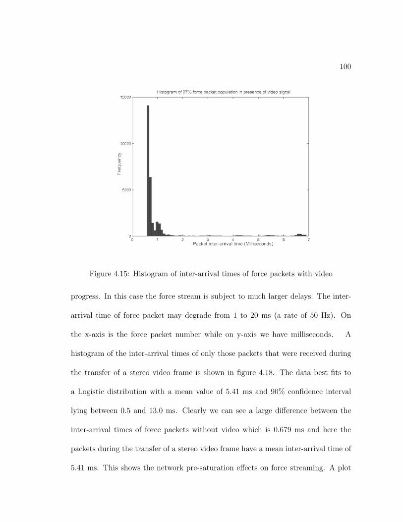
100
Figure 4.15: Histogram of inter-arrival times of force packets with video
progress. In this case the force stream is subject to much larger delays. The inter-
arrival time of force packet may degrade from 1 to 20 ms (a rate of 50 Hz). On
the x-axis is the force packet number while on y-axis we have milliseconds. A
histogram of the inter-arrival times of only those packets that were received during
the transfer of a stereo video frame is shown in figure 4.18. The data best fits to
a Logistic distribution with a mean value of 5.41 ms and 90% confidence interval
lying between 0.5 and 13.0 ms. Clearly we can see a large difference between the
inter-arrival times of force packets without video which is 0.679 ms and here the
packets during the transfer of a stereo video frame have a mean inter-arrival time of
5.41 ms. This shows the network pre-saturation effects on force streaming. A plot
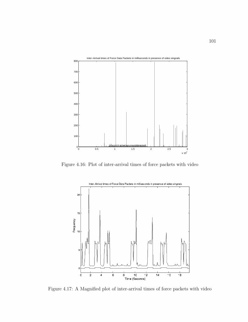
101
0 0.5 1 1.5 2 2.5 3
x 104
0
100
200
300
400
500
600
700
800Inter−Arrival times of Force Data Packets in milliseconds in presence of video singnals
Figure 4.16: Plot of inter-arrival times of force packets with video
��� ����� ��� ���������� � � � � � � � � ��� � � � �
Figure 4.17: A Magnified plot of inter-arrival times of force packets with video
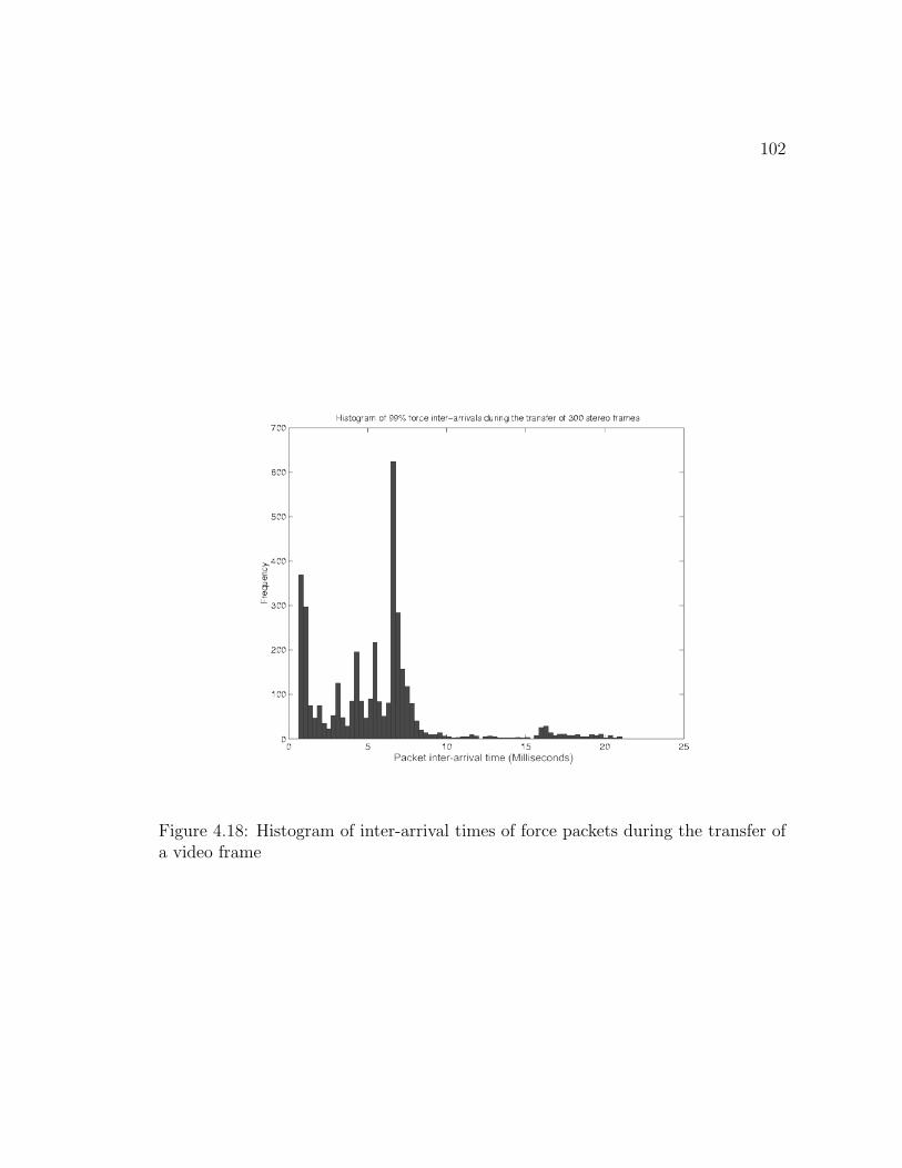
102
Figure 4.18: Histogram of inter-arrival times of force packets during the transfer ofa video frame
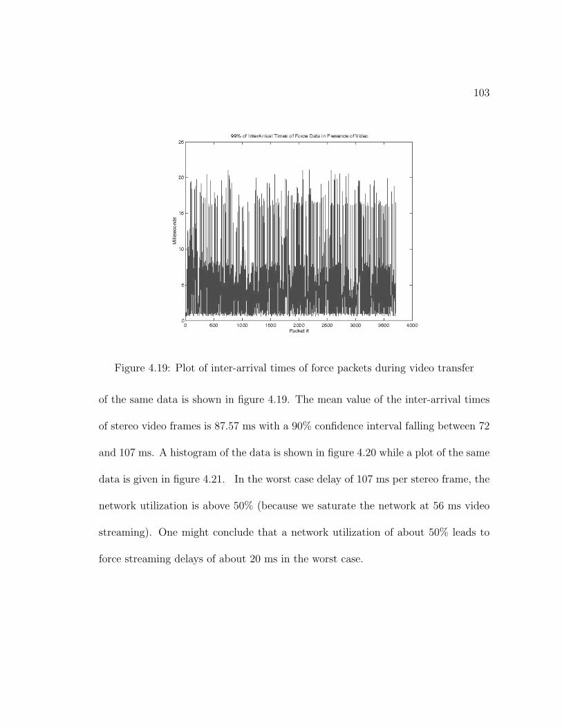
103
Figure 4.19: Plot of inter-arrival times of force packets during video transfer
of the same data is shown in figure 4.19. The mean value of the inter-arrival times
of stereo video frames is 87.57 ms with a 90% confidence interval falling between 72
and 107 ms. A histogram of the data is shown in figure 4.20 while a plot of the same
data is given in figure 4.21. In the worst case delay of 107 ms per stereo frame, the
network utilization is above 50% (because we saturate the network at 56 ms video
streaming). One might conclude that a network utilization of about 50% leads to
force streaming delays of about 20 ms in the worst case.
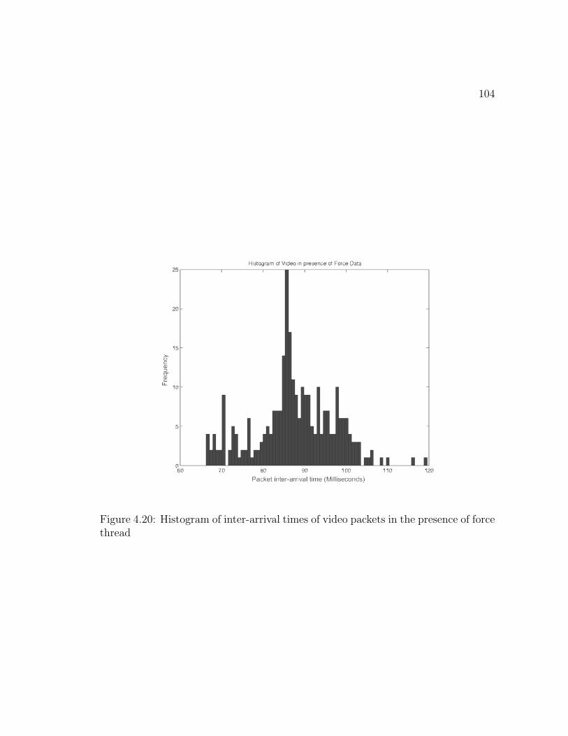
104
Figure 4.20: Histogram of inter-arrival times of video packets in the presence of forcethread
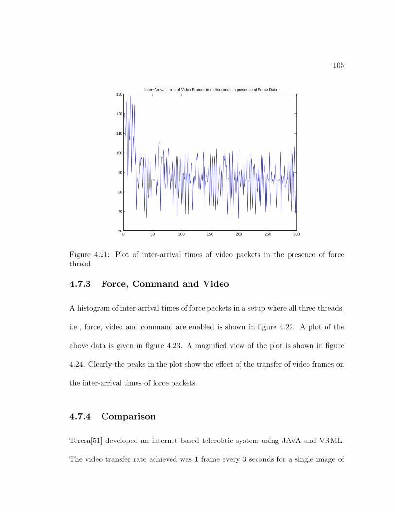
105
0 50 100 150 200 250 30060
70
80
90
100
110
120
130Inter−Arrival times of Video Frames in milliseconds in presence of Force Data
Figure 4.21: Plot of inter-arrival times of video packets in the presence of forcethread
4.7.3 Force, Command and Video
A histogram of inter-arrival times of force packets in a setup where all three threads,
i.e., force, video and command are enabled is shown in figure 4.22. A plot of the
above data is given in figure 4.23. A magnified view of the plot is shown in figure
4.24. Clearly the peaks in the plot show the effect of the transfer of video frames on
the inter-arrival times of force packets.
4.7.4 Comparison
Teresa[51] developed an internet based telerobtic system using JAVA and VRML.
The video transfer rate achieved was 1 frame every 3 seconds for a single image of
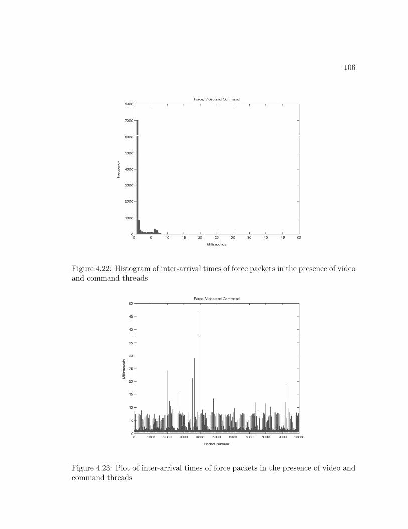
106
Figure 4.22: Histogram of inter-arrival times of force packets in the presence of videoand command threads
Figure 4.23: Plot of inter-arrival times of force packets in the presence of video andcommand threads
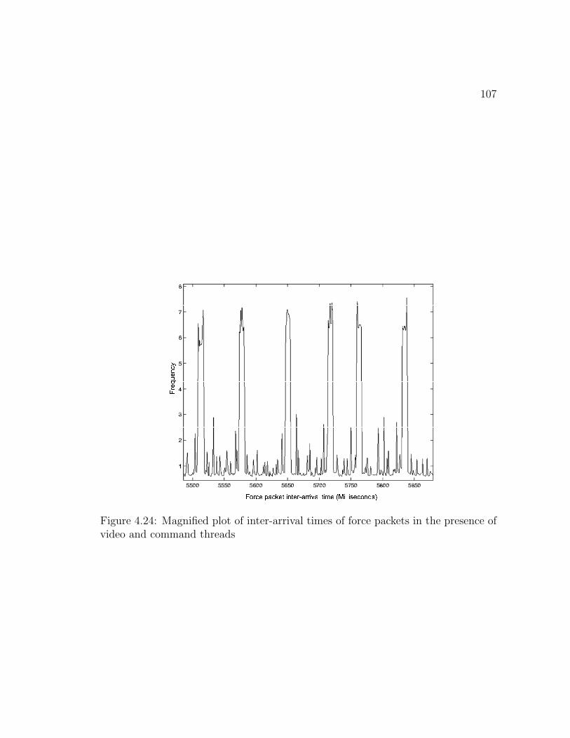
107
����� ������� ������� � � ��� � �� � � � ���� � ���� �� � � � ����� ���������
Figure 4.24: Magnified plot of inter-arrival times of force packets in the presence ofvideo and command threads
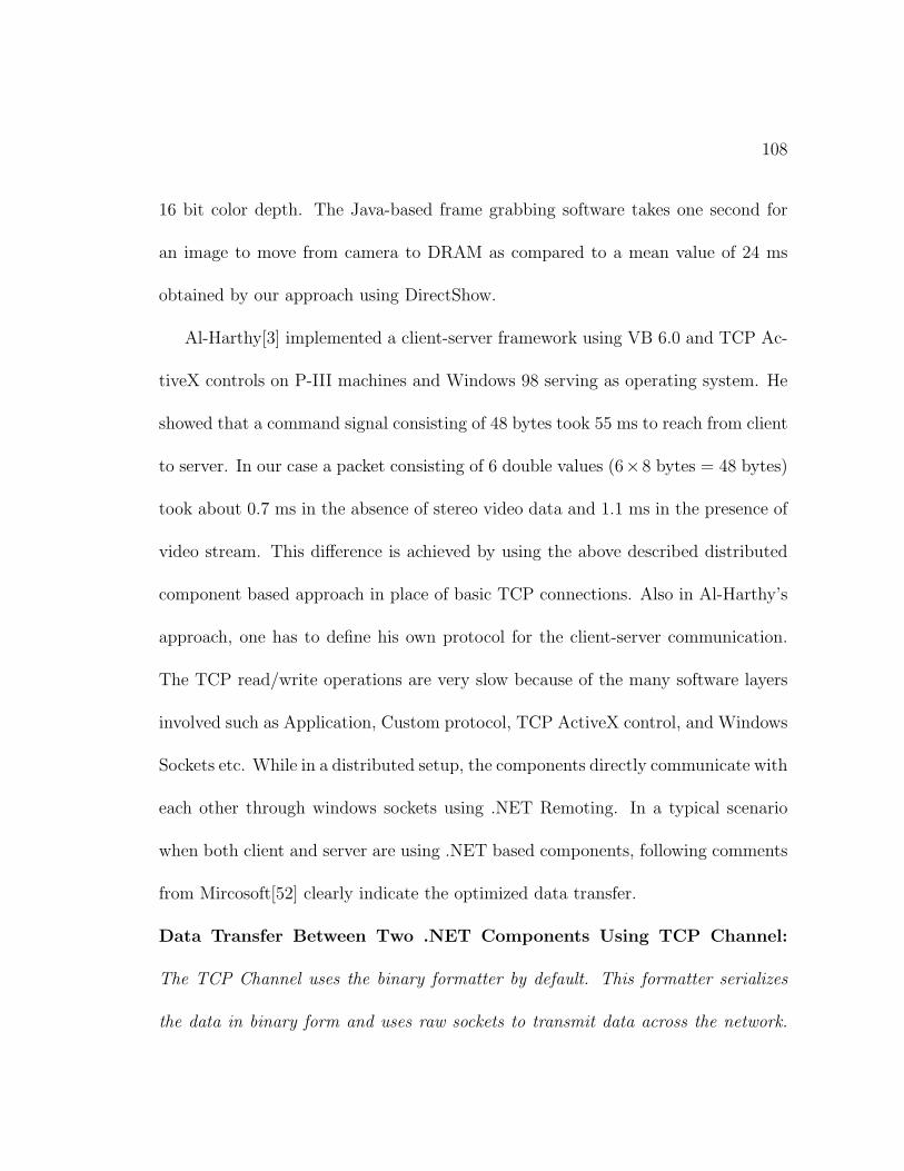
108
16 bit color depth. The Java-based frame grabbing software takes one second for
an image to move from camera to DRAM as compared to a mean value of 24 ms
obtained by our approach using DirectShow.
Al-Harthy[3] implemented a client-server framework using VB 6.0 and TCP Ac-
tiveX controls on P-III machines and Windows 98 serving as operating system. He
showed that a command signal consisting of 48 bytes took 55 ms to reach from client
to server. In our case a packet consisting of 6 double values (6×8 bytes = 48 bytes)
took about 0.7 ms in the absence of stereo video data and 1.1 ms in the presence of
video stream. This difference is achieved by using the above described distributed
component based approach in place of basic TCP connections. Also in Al-Harthy’s
approach, one has to define his own protocol for the client-server communication.
The TCP read/write operations are very slow because of the many software layers
involved such as Application, Custom protocol, TCP ActiveX control, and Windows
Sockets etc. While in a distributed setup, the components directly communicate with
each other through windows sockets using .NET Remoting. In a typical scenario
when both client and server are using .NET based components, following comments
from Mircosoft[52] clearly indicate the optimized data transfer.
Data Transfer Between Two .NET Components Using TCP Channel:
The TCP Channel uses the binary formatter by default. This formatter serializes
the data in binary form and uses raw sockets to transmit data across the network.
109
This method is ideal if your object is deployed in a closed environment within the
confines of a firewall. This approach is more optimized since it uses sockets to com-
municate binary data between objects. Using the TCP channel to expose your object
gives you the advantage of low overhead in closed environments.
Huosheng et al.[53] discussed the development of Internet-based telerobotic systems.
They have used JAVA for network interfacing and video while the robot controller
is written using C++. The machines used are P-III 500 Mhz with 128 MB RAM,
running Windows 98 as operating system. In a LAN setup, they quote a transfer
rate of 9-12 fps with time delays less than 200 ms for a single image of size 200×150
pixels. This is to be noted that the images are not bitmap but are compressed using
JPEG compression technique. In comparison to this, our stereo video client-server
transfers two images (stereo frame) of size 288 × 360 pixels at a rate of 17-18 fps
with a delay of around 58ms only.
Chapter 5
An Augmented Reality System for
Telerobotics
Augmented Reality can be used as an effective way to overcome the effects of time
delays in a telerobotic environment. The basic idea of an augmented reality system
is to mix the real and virtual information in order to provide the operator an aug-
mented view of the remote scene combined with a virtual representation of his own
local actions. This allows the operator to see how his action would fit into the scene
before being executed. The information that is added locally must fit seamlessly
into the remote real data so as to avoid any perplexities for the tele-operator. The
method that is generally adopted to augment a video stream uses overlaying virtual
graphics over real images.
110
111
Milgram et al. [54] stated three primary purposes for overlaying graphics for
teleoperation applications: 1) as a tool for probing the real remote environment
visible on video, 2) for enhancing video images through real object overlays, thus
compensating for image degradation due to occlusion of objects, and 3) for intro-
ducing realistic looking but non-existent graphic objects so that they appear to be a
part of the video scene. The last approach will be followed in the present work with
an aim to show the present location of the gripper point on the local video display in
the absence of fresh video data. To accomplish this task, it is proposed that a small
ball should be inserted in the most recent video scene at the position of the gripper
which is calculated locally from the command data coming from master arm, using
the direct geometric model of the robot. This should indicate the location of the
gripper one step ahead of time thus providing the operator a way to view the results
of his commands before the arrival of relevant video data.
Overlaying the graphics on real video, however, requires that a bidirectional one-
to-one mapping of coordinate spaces between the virtual world and the remote world
viewed through the video is established. For a stereo video system, this requires the
respective mappings of both right and left video frames. Simply stated, we must
know where a point in virtual 3D world will be projected on real stereo video. This
requires the knowledge of how some known fiducial points in 3D world are projected
on 2D image plane (pixel array).
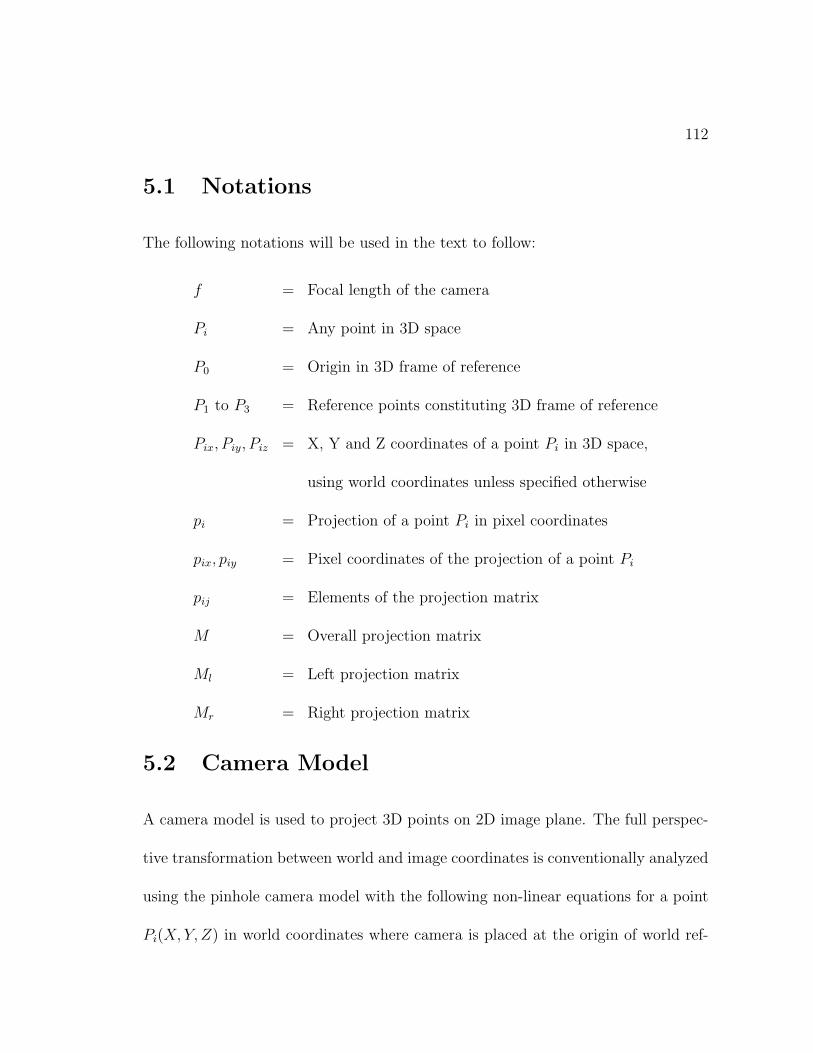
112
5.1 Notations
The following notations will be used in the text to follow:
f = Focal length of the camera
Pi = Any point in 3D space
P0 = Origin in 3D frame of reference
P1 to P3 = Reference points constituting 3D frame of reference
Pix, Piy, Piz = X, Y and Z coordinates of a point Pi in 3D space,
using world coordinates unless specified otherwise
pi = Projection of a point Pi in pixel coordinates
pix, piy = Pixel coordinates of the projection of a point Pi
pij = Elements of the projection matrix
M = Overall projection matrix
Ml = Left projection matrix
Mr = Right projection matrix
5.2 Camera Model
A camera model is used to project 3D points on 2D image plane. The full perspec-
tive transformation between world and image coordinates is conventionally analyzed
using the pinhole camera model with the following non-linear equations for a point
Pi(X,Y, Z) in world coordinates where camera is placed at the origin of world ref-
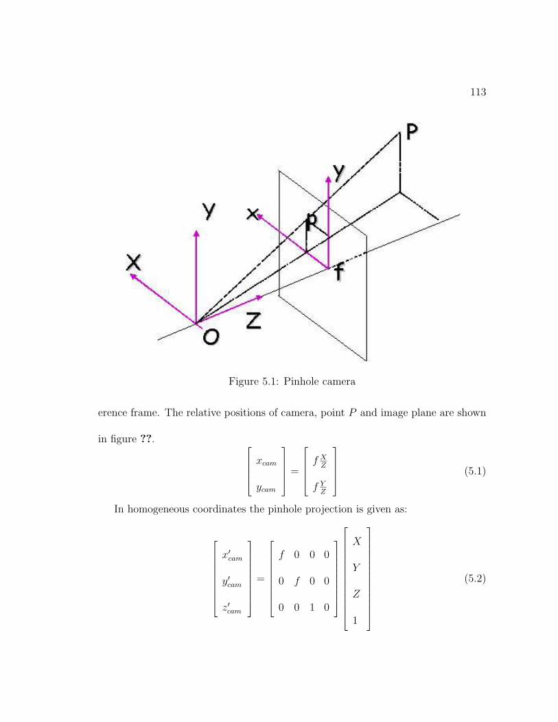
113
Figure 5.1: Pinhole camera
erence frame. The relative positions of camera, point P and image plane are shown
in figure ??. xcam
ycam
=
f XZ
f YZ
(5.1)
In homogeneous coordinates the pinhole projection is given as:
x′cam
y′cam
z′cam
=
f 0 0 0
0 f 0 0
0 0 1 0
X
Y
Z
1
(5.2)
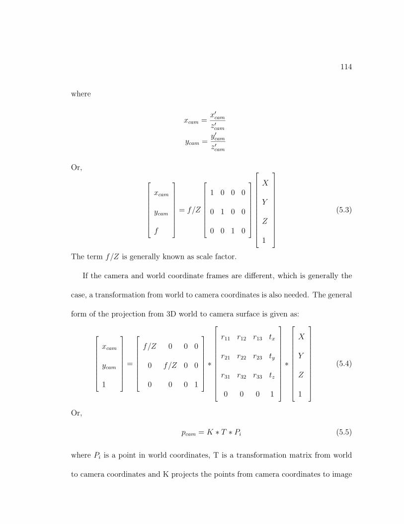
114
where
xcam =x′camz′cam
ycam =y′camz′cam
Or,
xcam
ycam
f
= f/Z
1 0 0 0
0 1 0 0
0 0 1 0
X
Y
Z
1
(5.3)
The term f/Z is generally known as scale factor.
If the camera and world coordinate frames are different, which is generally the
case, a transformation from world to camera coordinates is also needed. The general
form of the projection from 3D world to camera surface is given as:
xcam
ycam
1
=
f/Z 0 0 0
0 f/Z 0 0
0 0 0 1
∗
r11 r12 r13 tx
r21 r22 r23 ty
r31 r32 r33 tz
0 0 0 1
∗
X
Y
Z
1
(5.4)
Or,
pcam = K ∗ T ∗ Pi (5.5)
where Pi is a point in world coordinates, T is a transformation matrix from world
to camera coordinates and K projects the points from camera coordinates to image
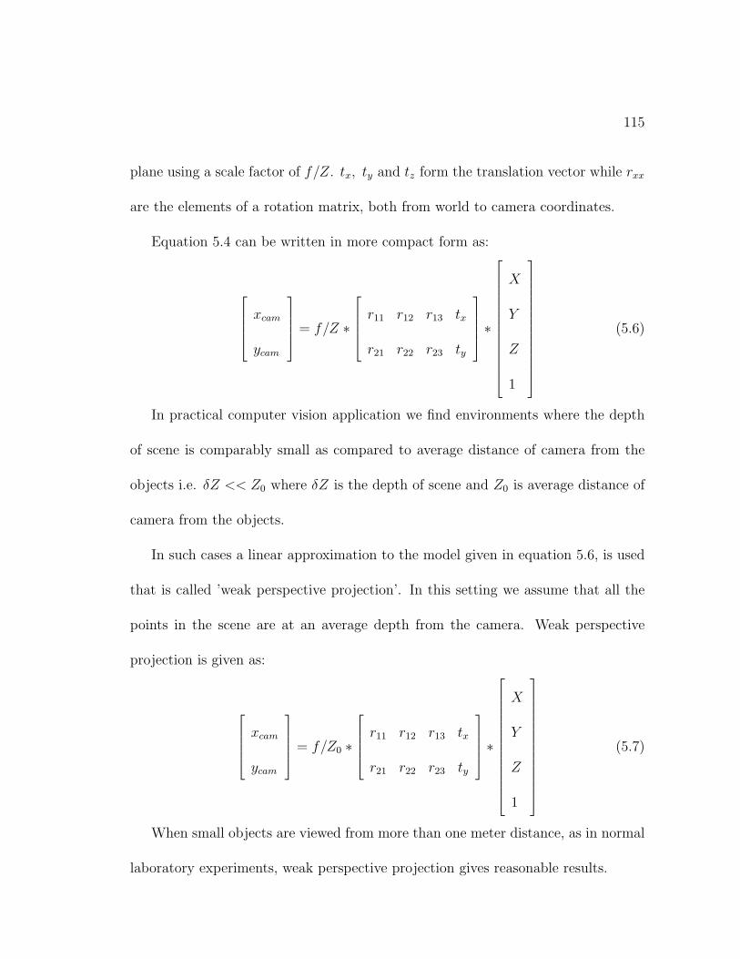
115
plane using a scale factor of f/Z. tx, ty and tz form the translation vector while rxx
are the elements of a rotation matrix, both from world to camera coordinates.
Equation 5.4 can be written in more compact form as:
xcam
ycam
= f/Z ∗
r11 r12 r13 tx
r21 r22 r23 ty
∗
X
Y
Z
1
(5.6)
In practical computer vision application we find environments where the depth
of scene is comparably small as compared to average distance of camera from the
objects i.e. δZ << Z0 where δZ is the depth of scene and Z0 is average distance of
camera from the objects.
In such cases a linear approximation to the model given in equation 5.6, is used
that is called ’weak perspective projection’. In this setting we assume that all the
points in the scene are at an average depth from the camera. Weak perspective
projection is given as:
xcam
ycam
= f/Z0 ∗
r11 r12 r13 tx
r21 r22 r23 ty
∗
X
Y
Z
1
(5.7)
When small objects are viewed from more than one meter distance, as in normal
laboratory experiments, weak perspective projection gives reasonable results.
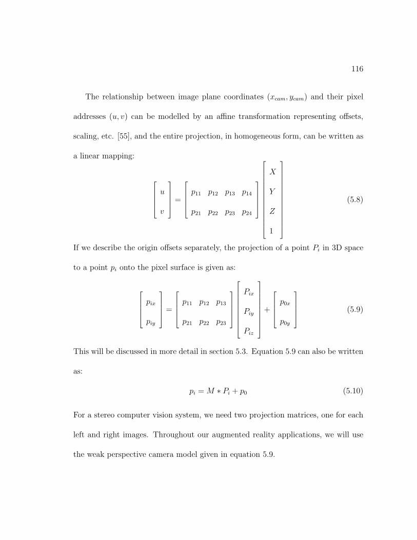
116
The relationship between image plane coordinates (xcam, ycam) and their pixel
addresses (u, v) can be modelled by an affine transformation representing offsets,
scaling, etc. [55], and the entire projection, in homogeneous form, can be written as
a linear mapping:
u
v
=
p11 p12 p13 p14
p21 p22 p23 p24
X
Y
Z
1
(5.8)
If we describe the origin offsets separately, the projection of a point Pi in 3D space
to a point pi onto the pixel surface is given as:
pix
piy
=
p11 p12 p13
p21 p22 p23
Pix
Piy
Piz
+
p0x
p0y
(5.9)
This will be discussed in more detail in section 5.3. Equation 5.9 can also be written
as:
pi = M ∗ Pi + p0 (5.10)
For a stereo computer vision system, we need two projection matrices, one for each
left and right images. Throughout our augmented reality applications, we will use
the weak perspective camera model given in equation 5.9.
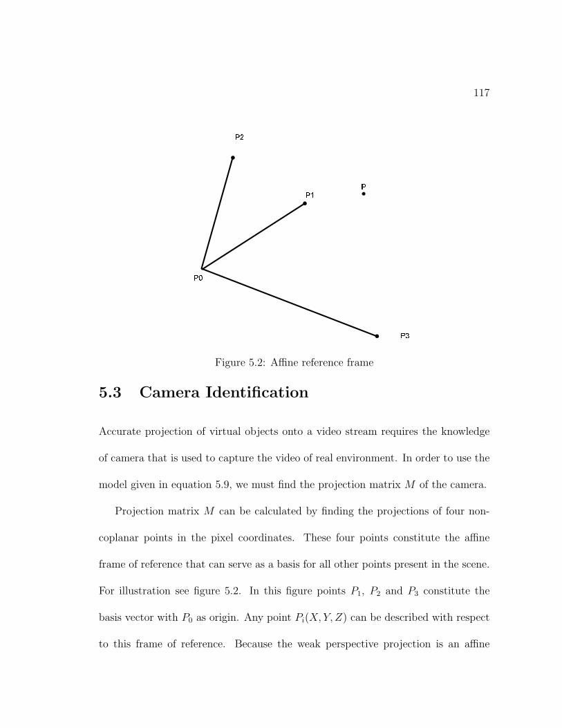
117
���
���
���
���
�
Figure 5.2: Affine reference frame
5.3 Camera Identification
Accurate projection of virtual objects onto a video stream requires the knowledge
of camera that is used to capture the video of real environment. In order to use the
model given in equation 5.9, we must find the projection matrix M of the camera.
Projection matrix M can be calculated by finding the projections of four non-
coplanar points in the pixel coordinates. These four points constitute the affine
frame of reference that can serve as a basis for all other points present in the scene.
For illustration see figure 5.2. In this figure points P1, P2 and P3 constitute the
basis vector with P0 as origin. Any point Pi(X, Y, Z) can be described with respect
to this frame of reference. Because the weak perspective projection is an affine
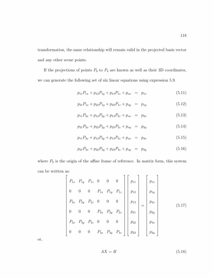
118
transformation, the same relationship will remain valid in the projected basis vector
and any other scene points.
If the projections of points P0 to P4 are known as well as their 3D coordinates,
we can generate the following set of six linear equations using expression 5.9.
p11P1x + p12P1y + p13P1z + pox = p1x (5.11)
p21P1x + p22P1y + p23P1z + poy = p1y (5.12)
p11P2x + p12P2y + p13P2z + pox = p2x (5.13)
p21P2x + p22P2y + p23P2z + poy = p2y (5.14)
p11P3x + p12P3y + p13P3z + pox = p3x (5.15)
p21P3x + p22P3y + p23P3z + poy = p3y (5.16)
where P0 is the origin of the affine frame of reference. In matrix form, this system
can be written as:
P1x P1y P1z 0 0 0
0 0 0 P1x P1y P1z
P2x P2y P2z 0 0 0
0 0 0 P2x P2y P2z
P3x P3y P3z 0 0 0
0 0 0 P3x P3y P3z
p11
p12
p13
p21
p22
p23
=
p1x
p1y
p2x
p2y
p3x
p3y
(5.17)
or,
AX = B (5.18)
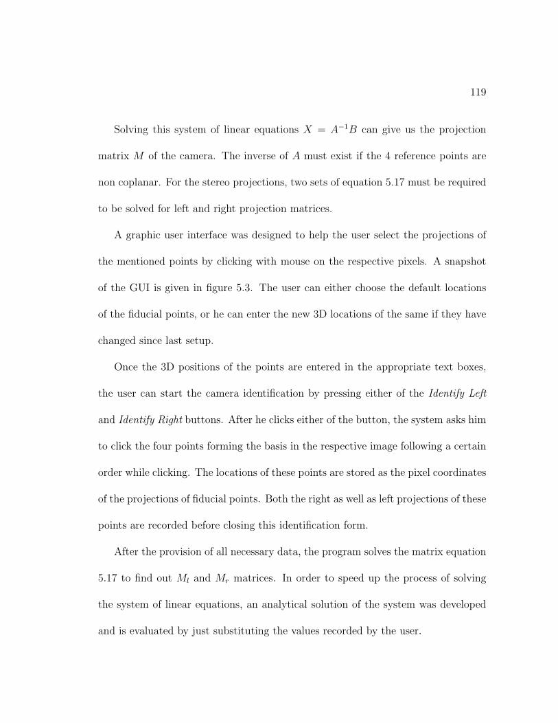
119
Solving this system of linear equations X = A−1B can give us the projection
matrix M of the camera. The inverse of A must exist if the 4 reference points are
non coplanar. For the stereo projections, two sets of equation 5.17 must be required
to be solved for left and right projection matrices.
A graphic user interface was designed to help the user select the projections of
the mentioned points by clicking with mouse on the respective pixels. A snapshot
of the GUI is given in figure 5.3. The user can either choose the default locations
of the fiducial points, or he can enter the new 3D locations of the same if they have
changed since last setup.
Once the 3D positions of the points are entered in the appropriate text boxes,
the user can start the camera identification by pressing either of the Identify Left
and Identify Right buttons. After he clicks either of the button, the system asks him
to click the four points forming the basis in the respective image following a certain
order while clicking. The locations of these points are stored as the pixel coordinates
of the projections of fiducial points. Both the right as well as left projections of these
points are recorded before closing this identification form.
After the provision of all necessary data, the program solves the matrix equation
5.17 to find out Ml and Mr matrices. In order to speed up the process of solving
the system of linear equations, an analytical solution of the system was developed
and is evaluated by just substituting the values recorded by the user.
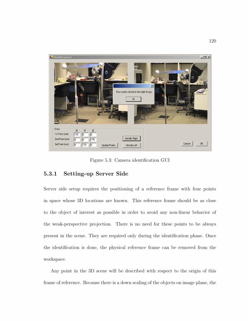
120
Figure 5.3: Camera identification GUI
5.3.1 Setting-up Server Side
Server side setup requires the positioning of a reference frame with four points
in space whose 3D locations are known. This reference frame should be as close
to the object of interest as possible in order to avoid any non-linear behavior of
the weak-perspective projection. There is no need for these points to be always
present in the scene. They are required only during the identification phase. Once
the identification is done, the physical reference frame can be removed from the
workspace.
Any point in the 3D scene will be described with respect to the origin of this
frame of reference. Because there is a down scaling of the objects on image plane, the
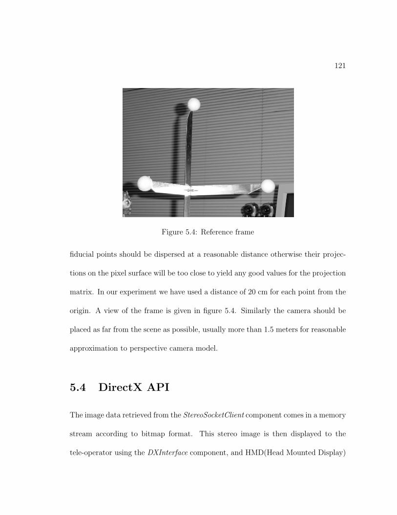
121
Figure 5.4: Reference frame
fiducial points should be dispersed at a reasonable distance otherwise their projec-
tions on the pixel surface will be too close to yield any good values for the projection
matrix. In our experiment we have used a distance of 20 cm for each point from the
origin. A view of the frame is given in figure 5.4. Similarly the camera should be
placed as far from the scene as possible, usually more than 1.5 meters for reasonable
approximation to perspective camera model.
5.4 DirectX API
The image data retrieved from the StereoSocketClient component comes in a memory
stream according to bitmap format. This stereo image is then displayed to the
tele-operator using the DXInterface component, and HMD(Head Mounted Display)
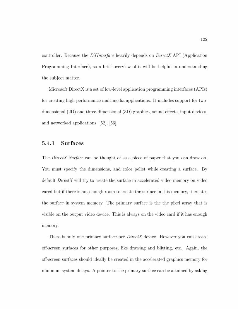
122
controller. Because the DXInterface heavily depends on DirectX API (Application
Programming Interface), so a brief overview of it will be helpful in understanding
the subject matter.
Microsoft DirectX is a set of low-level application programming interfaces (APIs)
for creating high-performance multimedia applications. It includes support for two-
dimensional (2D) and three-dimensional (3D) graphics, sound effects, input devices,
and networked applications [52], [56].
5.4.1 Surfaces
The DirectX Surface can be thought of as a piece of paper that you can draw on.
You must specify the dimensions, and color pellet while creating a surface. By
default DirectX will try to create the surface in accelerated video memory on video
cared but if there is not enough room to create the surface in this memory, it creates
the surface in system memory. The primary surface is the the pixel array that is
visible on the output video device. This is always on the video card if it has enough
memory.
There is only one primary surface per DirectX device. However you can create
off-screen surfaces for other purposes, like drawing and blitting, etc. Again, the
off-screen surfaces should ideally be created in the accelerated graphics memory for
minimum system delays. A pointer to the primary surface can be attained by asking
123
for a BackBuffer from the DirectX Device. It is typical to have a BackBuffer for the
image on primary surface. The BackBuffer can be switched easily with the current
displayed frame. The purpose of this framework is to allow maximum flexibility
while drawing 3D objects onto the screen. The frame data that is to be displayed
next on the screen in generally manipulated on the off-screen surfaces.
5.4.2 Page Flipping, HAL (Hardware Abstraction Layer)
Once every video frame, the back buffer is updated from one or more off-screen
surfaces and then the back buffer is presented to the display screen. This process
is called page flipping. During this process, the graphics microprocessor flips the
addresses of front and back buffers and the next image drawn on the screen comes
from the previous back buffer. While the previous front buffer is now back buffer
and is ready to be used for the coming video frame. Ideally this process takes place
in video hardware and is extremely fast not allowing any shearing or tearing of the
image while changing from one video frame to the next.
In our case, during each flipping operation a complete stereo image will be sent
down to the HMD. This image will be acquired from the network video stream while
the drawing of the current image on graphics screen is in progress. A stereo snapshot
that is just to be flipped to the HMD is shown in figure 5.5. In short, the stereo
video is updated on local display in a page-by-page format and not pixel-by-pixel
124
Figure 5.5: A stereo snapshot ready to be displayed on HMD
which delivers great benefits in terms of reducing time delays.
Direct3D, a component of DirectX, delivers real-time full 3D rendering and trans-
parent access to hardware graphics acceleration boards. In other words, it allows
Windows to make use of the advanced graphics capabilities found in 3D hardware
graphics boards. However in doing so it utilizes the HAL (Hardware Abstration
Layer). The use of HAL guarantees increased stability and portability of DirectX
application. HAL serves as a thin wrapper around the DDI(Device Driver Interface).
Let us try to understand the need for a HAL wrapper. If we want to draw a
circle on the video display, instead of drawing it pixel-by-pixel, we would like to
create it with a single circle(x,y, radius) command, where x, y indicate the origin
of the circle. Usually this command should be supplied by the graphics hardware
vendor through DDI. Each hardware vendor will supply a different implementation
for the circle method. So our DirectX application will be restricted to only one
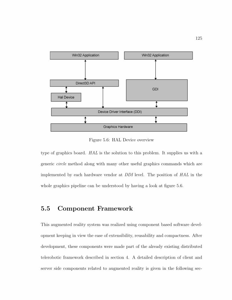
125
Figure 5.6: HAL Device overview
type of graphics board. HAL is the solution to this problem. It supplies us with a
generic circle method along with many other useful graphics commands which are
implemented by each hardware vendor at DDI level. The position of HAL in the
whole graphics pipeline can be understood by having a look at figure 5.6.
5.5 Component Framework
This augmented reality system was realized using component based software devel-
opment keeping in view the ease of extensibility, reusability and compactness. After
development, these components were made part of the already existing distributed
telerobotic framework described in section 4. A detailed description of client and
server side components related to augmented reality is given in the following sec-
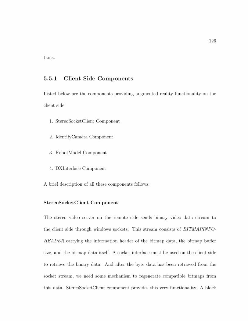
126
tions.
5.5.1 Client Side Components
Listed below are the components providing augmented reality functionality on the
client side:
1. StereoSocketClient Component
2. IdentifyCamera Component
3. RobotModel Component
4. DXInterface Component
A brief description of all these components follows:
StereoSocketClient Component
The stereo video server on the remote side sends binary video data stream to
the client side through windows sockets. This stream consists of BITMAPINFO-
HEADER carrying the information header of the bitmap data, the bitmap buffer
size, and the bitmap data itself. A socket interface must be used on the client side
to retrieve the binary data. And after the byte data has been retrieved from the
socket stream, we need some mechanism to regenerate compatible bitmaps from
this data. StereoSocketClient component provides this very functionality. A block
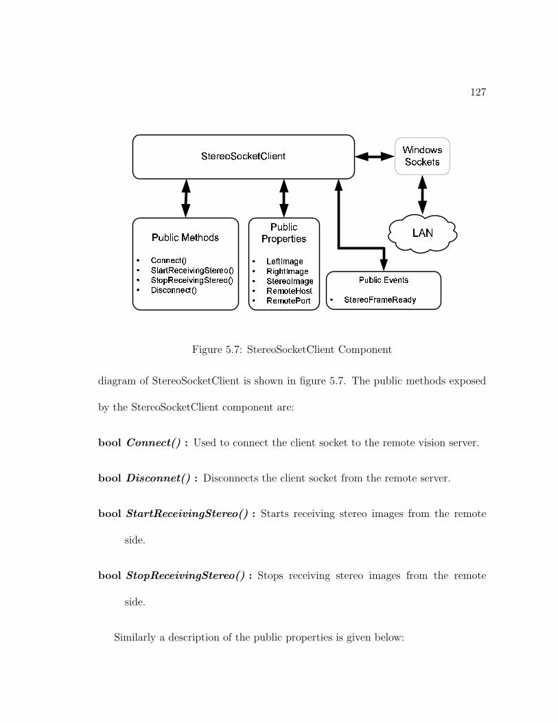
127
��� �������� �� ������
� � ��� ��� � �� ������ ��� � �����
������� � ������ ������
�� �!!"# $ % &'�( )�* ( +�,- ,�. /. 0 1�'�( ,�* ,2�3 45�6 7�8:9�;< ;�= >= ? @:5:6 ;�A ;7�B CD�E F G H�II J:G K L M
NPO�Q�R S TNPU V�W�X�U Y S X�Z
[\ ] ^ _ `ba c:\d�e f:g h i jbk f�lm�n o�p oq:r sutv�owyx�zP{ | x�}�{~ |�y���P� � ������� �
������ � �u��� �:� � �
��� ��� ����:� ���u������� ��
�����
Figure 5.7: StereoSocketClient Component
diagram of StereoSocketClient is shown in figure 5.7. The public methods exposed
by the StereoSocketClient component are:
bool Connect() : Used to connect the client socket to the remote vision server.
bool Disconnet() : Disconnects the client socket from the remote server.
bool StartReceivingStereo() : Starts receiving stereo images from the remote
side.
bool StopReceivingStereo() : Stops receiving stereo images from the remote
side.
Similarly a description of the public properties is given below:
128
Bitmap LeftImage : A get only property that returns a copy of the freshly re-
ceived left image.
Bitmap RightImage : A get only property that returns a copy of the freshly
received right image.
Bitmap StereoImage : Returns a copy of current stereo image in bitmap format
combining left and right images in side by side fashion.
String RemoteHost : A get/set property specifying the DNS name of the com-
puter running vision server.
int RemotePort : Get/set property indicating the port address of RemoteHost.
In order to use the component, first the calling thread creates an instance of the
StereoClientComponent. RemoteHost and RemotePort properties are set properly
for the computer running the vision server. Then StartReceivingStereo() method of
the component is called. This call creates a separate thread for receiving the images.
Whenever it receives fresh copies of both left and right images, a StereoFrameReady
event is fired by the image receiving thread and the fresh copies of the images are
available immediately through LeftImage and RightImage properties. This event is
synchronous which means that until the called thread has read the image data, the
event stops the execution of calling thread which in our case is the image receiving
thread. By this, we ensure that the image data is not overwritten during the copy
129
operation. If the container of the StereoSocketClient component needs the stereo
image instead, it can read the StereoImage property of the component that returns
a single stereo image in left/right format.
IdentifyCamera Component
As explained in section 5.3, camera identification must be done to accurately po-
sition 3D objects on the pixel plane. For a given set of four non-coplanar points
constituting the basis vector, IdentifyCamera component can be used to find out
the camera projection matrices for both left and right cameras.
The component is initialized with the default positions of fiducial points which
can be changed. UpdatePics() method of IdentifyCamera component can be used
to update the left and right images whenever they are available through the video
stream provided by StereoSocketClient component in the form of bitmap images.
These pictures are updated on the GUI provided by the component as shown in
figure 5.3.
Public properties of the component are the following:
LeftProjectionMatrix : Projection matrix for the left camera.
RightProjectionMatrix : Projection matrix for the right camera.
LeftOriginCorrection : Returns left origin correction in number of pixels to be
added to 3D projections of the virtual points.
130
RightOriginCorrection : Right origin correction in number of pixels.
On the closure of the GUI, both the left and right projection matrices Ml and Mr,
respectively, are available to the calling thread based on the mouse clicks of the user.
RobotModel Component
This component plays an important role in the realization of the augmented reality
system. This acts as a local proxy of the PUMA robot which is also available
in the form of IDecisionServer interface. The difference between the two is that
IDecisionServer is an active proxy of the DecisionServer component. Any call to
the public methods or properties of IDecisionServer interface will be directed to
the active instance of DecisionServer component on the server side through .NET
remoting. While the RobotModel component is a passive proxy which is, in no
way, connected to the instance of DecisionServer. This setup requiring the use of
RobotModel is needed to locate the future position of the robot gripper based on the
current command that is being sent to the robot through IDecisionServer interface.
RobotModel component provides following public methods:
bool InitializeModel() : Initializes the RobotModel to the default reference po-
sition. This position is the same as used to initialize the PUMA component
on the server side. However the method is overloaded and can initialize the
model to any given set of joint angles as well.
131
bool MoveModel(double[] incAngleData) : Moves the model using incremen-
tal joint space values. The parameter incAngleData specifies the incremental
values of joint space variables.
bool MoveModel(pVec, oMat) : Incrementally moves the robot model in carte-
sian space. The parameters pVec and oMat specify the incremental values of
position vector and orientation matrices.
The public properties exposed by the component are:
PositionVector : Retrieves the current position vector of the model (PUMA grip-
per).
OrientationMatrix : Current orientation matrix of the robot gripper.
RobotAngles : A write only property for setting the current joint space variables
of the RobotModel.
RobotModel component can be thought of as a thin copy of PUMA component
removing the robot hardware related functionality. It has complete inverse geometric
model of the robot that it uses to move the robot when its MoveModel method is
invoked with incremental position vector and orientation matrix. While moving the
model, the component also takes care of the RobotFrameMode of PUMA robot. Upon
moving it using the incremental joint space variables, it uses the direct geometric
model to calculate the current position vector and orientation matrix.
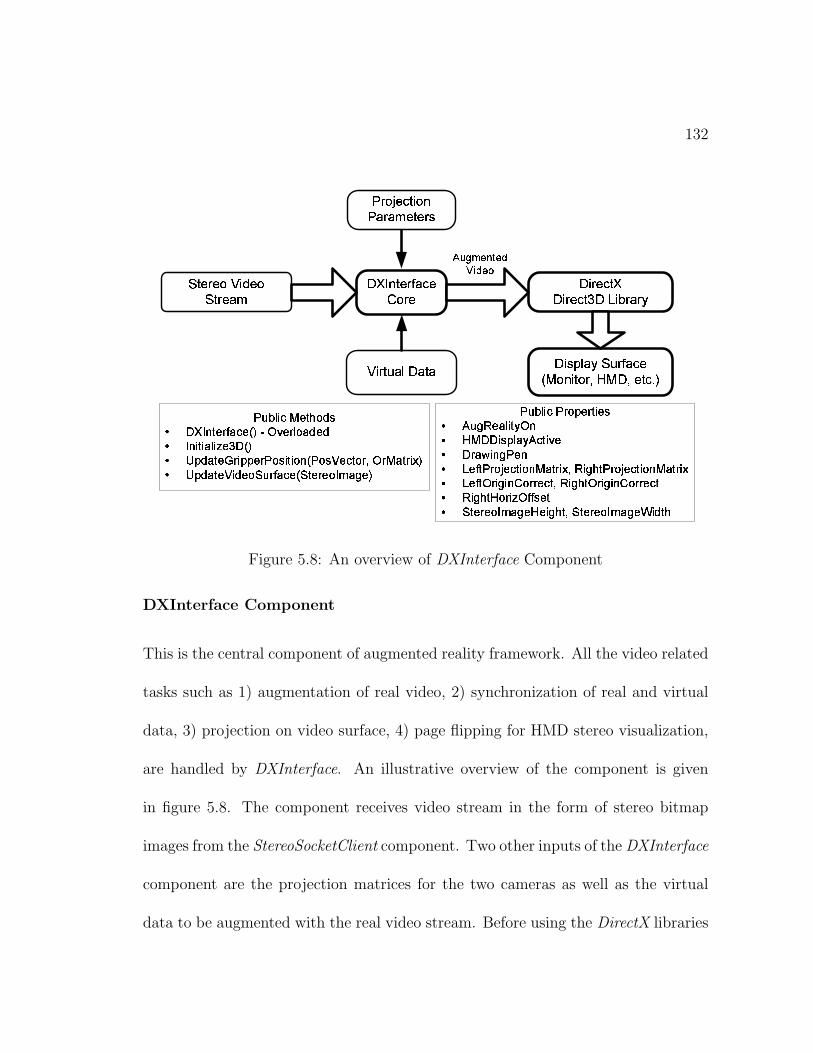
132
��� ��� ����� � ������ � �����
����� � � � � � � �������� �
� � � � � �� � ��� � � ��� � � � � �
� � ! ��� � � � ��� ���"�#� �$� %
�� � � &�� ' � ��� � � %#(�' ���)��& � � � ���* + � � � ��� ,�- +.� ,���� � / 0
1$2�3�4 5 6�7�8 9 :#; <�=>�?�@ A B C#D E F#G C#H I J K�L C#D M N�F O C OP Q�R S R T#U R V W�X#Y�Z [\�] ^#_ ` a�b�c d ]�] a#c e$f g�d ` d f#h�i e�f g j�a�k ` f#c l m�c n�_ ` c d o pq�r s#t u v w�x s#v�y#z${#| } t�~ v#� z u v�| v�y�� ��t �#v �
�${���� x ~���| y#r v#| u x v ���� �����#�#� � � � ������������ ����� � � �� ¡ � ¢ £¤�¥ ¦ §�¨ © ª «�¬#© ®�¯ ° ±�² ³ ´ ®�µ ° ¶ ³#·�¸�¹ ° ² ¶ º#»�¼�¶ ½�¾ ° ±$² ³ ´ ®�µ ° ¶ ³#·�¸�¹ ° ² ¶ º¿ À�Á  Ã�Ä Å Æ�Å Ç È�É#Ä Ä À�Ê Â Ë�Ì�Å Æ�Í Â ÃÎÄ Å Æ Å Ç È�É#Ä Ä À�Ê ÂÏ�Ð Ñ�Ò Ó Ô�Õ#Ö Ð × Ø�Ù Ù Ú Û ÓÜ Ý Þ#ß Þ�à�á â�ã ä�Þ#å�Þ#æ ä�ç Ý è Ü Ý Þ#ß Þ�à�á âÎã�ä#Þ éêæ ë�Ý ç
ì$í î ï�ð ñ ò ð óô�õ ó ð ö
Figure 5.8: An overview of DXInterface Component
DXInterface Component
This is the central component of augmented reality framework. All the video related
tasks such as 1) augmentation of real video, 2) synchronization of real and virtual
data, 3) projection on video surface, 4) page flipping for HMD stereo visualization,
are handled by DXInterface. An illustrative overview of the component is given
in figure 5.8. The component receives video stream in the form of stereo bitmap
images from the StereoSocketClient component. Two other inputs of the DXInterface
component are the projection matrices for the two cameras as well as the virtual
data to be augmented with the real video stream. Before using the DirectX libraries
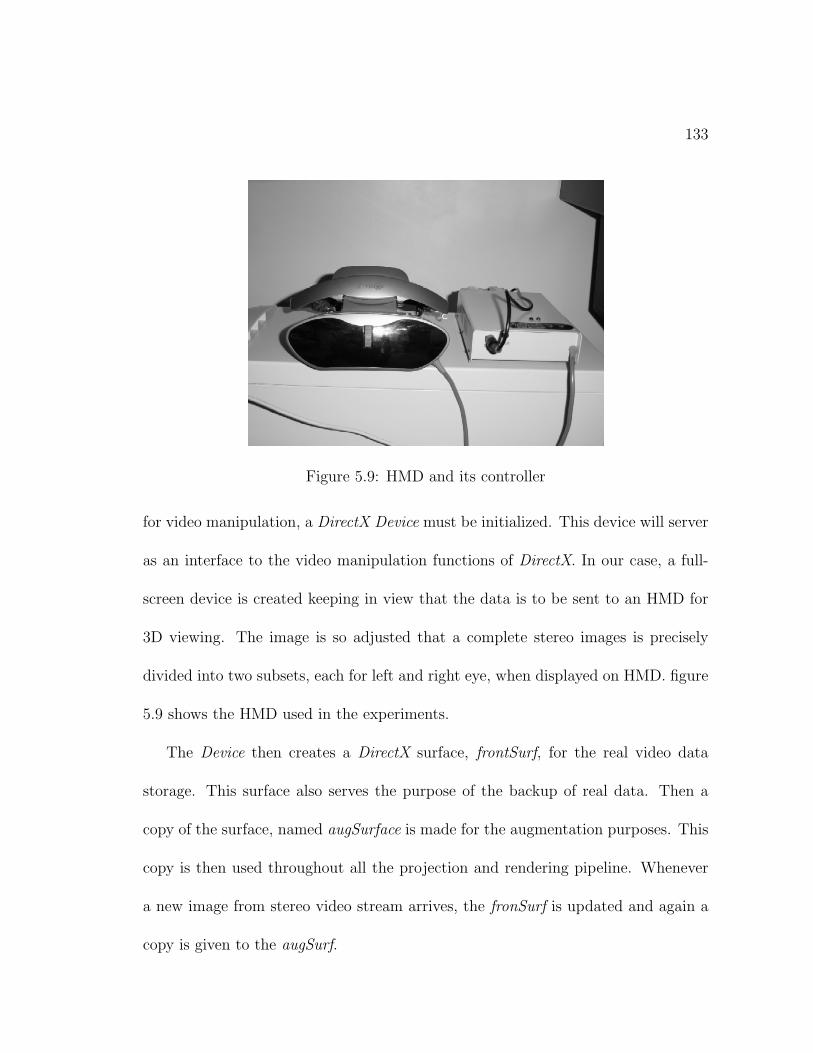
133
Figure 5.9: HMD and its controller
for video manipulation, a DirectX Device must be initialized. This device will server
as an interface to the video manipulation functions of DirectX. In our case, a full-
screen device is created keeping in view that the data is to be sent to an HMD for
3D viewing. The image is so adjusted that a complete stereo images is precisely
divided into two subsets, each for left and right eye, when displayed on HMD. figure
5.9 shows the HMD used in the experiments.
The Device then creates a DirectX surface, frontSurf, for the real video data
storage. This surface also serves the purpose of the backup of real data. Then a
copy of the surface, named augSurface is made for the augmentation purposes. This
copy is then used throughout all the projection and rendering pipeline. Whenever
a new image from stereo video stream arrives, the fronSurf is updated and again a
copy is given to the augSurf.
134
The virtual data in our case is the 3D gripper position. We need to draw a
small ball at the supplied gripper position. DXInterface applies the camera model
given in equation 5.17 utilizing the supplied left and right projection matrices. The
component while projecting the point to the real data surface must also take into
account the horizontal offset for the right image because the stereo image is saved
as a single image in the video memory. If we need to write something for the right
frame of stereo image, a horizontal offset equal to the image width of a single image
must be added to any point being projected to the right hand side.
Whenever a new gripper position is received to be displayed, DXInterface uses
augSurf to write virtual data to the video surface. After the augmentation, the
data is rendered using Present() method of DirectX interface. This operation of
presenting the the data to the display screen is accomplished using page flipping.
The video memory address of front buffer is flipped to the back buffer and vice
versa. All the information on the previous front surface is discarded during flipping
operation.
DXInterface provides following public methods:
DXInterface() : An overloaded constructor that accepts left, right projection ma-
trices, screen size and other parameters to be used in 3D Device initialization.
Initialize3D() : Initializes the 3D Device in full screen mode.
UpdateGripperPosition(posVector, orMatrix) : Augments the real display with
135
virtual ball on the supplied location specified by the parameters posVec-
tor(Position Vector) and orMatrix(Orientation Matrix). Although we do not
use the orMatrix in placing the virtual ball in 3D space, it may be useful in
possible future work in placing complex 3D objects.
UpdateVideoSurface(StereoImage) : This method updates the current video
surface when a new stereo frame arrives from the network video stream. In
drawing the new real data, the virtual data is preserved.
The public properties exposed by the component are as under:
bool AugRealityOn : Can be used to toggle the augmented reality on stereo dis-
play.
bool HMDDisplayActive : A read only property indicating whether 3D Device
is sending data to HMD or not.
DrawingPen : The color to be used to draw augmented data.
LeftProjectionMatrix : Left camera projection matrix.
RightProjectionMatrix : Right camera projection matrix.
LeftOriginCorrect : Origin correction in number of pixels for left image.
RightOriginCorrect : Origin correction in number of pixels for right image.
136
RightHorizOffset : Horizontal offset in pixels for drawing virtual data to right
image, with respect to left image.
StereoImageHeight : Stereo image height.
StereoImageWidth : Stereo image width.
5.5.2 Server Side
Server side acquires and sends the stereo image data through windows network sock-
ets. However only the client side is responsible for major augmented reality business.
In section 3, we discussed the server side for the stereo video client-server framework.
The same vision server is used in the AR framework. StereoSocketClient is intelli-
gent enough to understand the socket stream sent by the vision server developed for
MFC(Microsoft Foundation Classes) client-server setup.
5.6 The Complete Augmented Reality System
All of these components have been combined together to form a complete augmented
reality system on the client side. The system provides the augmented reality func-
tionality through the following steps:
1. Input from the user is taken through the MasterArm component.
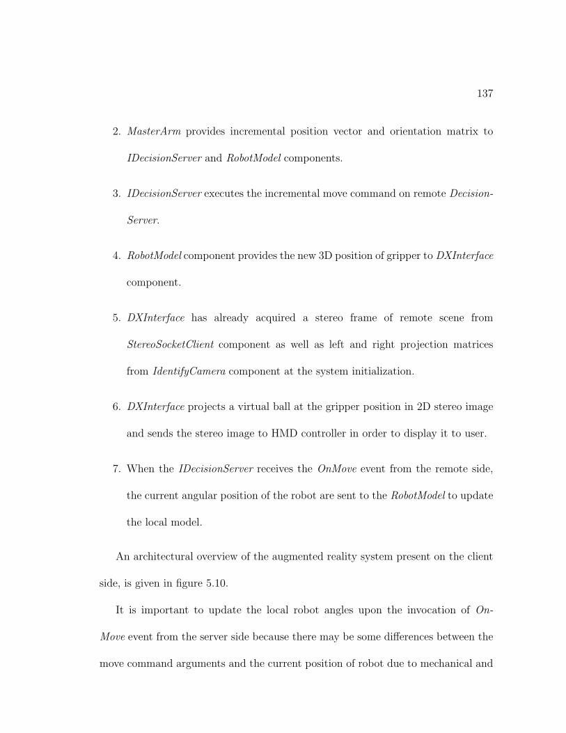
137
2. MasterArm provides incremental position vector and orientation matrix to
IDecisionServer and RobotModel components.
3. IDecisionServer executes the incremental move command on remote Decision-
Server.
4. RobotModel component provides the new 3D position of gripper to DXInterface
component.
5. DXInterface has already acquired a stereo frame of remote scene from
StereoSocketClient component as well as left and right projection matrices
from IdentifyCamera component at the system initialization.
6. DXInterface projects a virtual ball at the gripper position in 2D stereo image
and sends the stereo image to HMD controller in order to display it to user.
7. When the IDecisionServer receives the OnMove event from the remote side,
the current angular position of the robot are sent to the RobotModel to update
the local model.
An architectural overview of the augmented reality system present on the client
side, is given in figure 5.10.
It is important to update the local robot angles upon the invocation of On-
Move event from the server side because there may be some differences between the
move command arguments and the current position of robot due to mechanical and
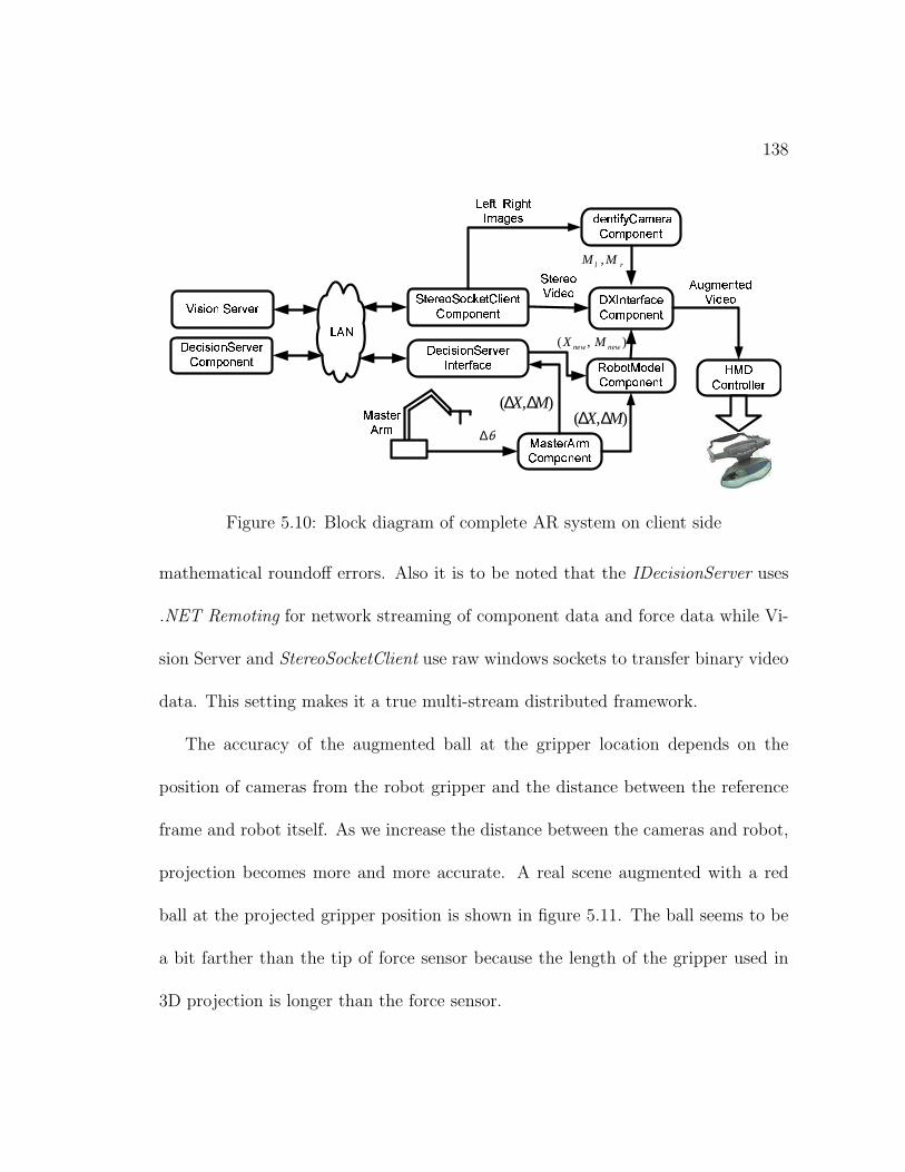
138
������� ��� ������� ����� �������������
� ���
��� ��� ����������� ��� ��� � ����� �������������
���� �� ��� ! "����� �������������
#%$&�� ���� � � � � ��
��� ��� ���'(� )����
rl MM ,
)����� � ! * � "��+��� "� �������������
����! � ,�-(� .�/�� �+"�.����
������� ��� �������� ���� �� ��� ! "����
$+"�� � ��� �%� �� �������������
),( MX ∆∆$+"�� � ������ �
-���0���� $+��)�� �� ���&���������
�%1�.������� ��)'(� )����
2(3 4�3 5�6+7�8�9 :�8�9
),( newnew MX
),( MX ∆∆θ∆
Figure 5.10: Block diagram of complete AR system on client side
mathematical roundoff errors. Also it is to be noted that the IDecisionServer uses
.NET Remoting for network streaming of component data and force data while Vi-
sion Server and StereoSocketClient use raw windows sockets to transfer binary video
data. This setting makes it a true multi-stream distributed framework.
The accuracy of the augmented ball at the gripper location depends on the
position of cameras from the robot gripper and the distance between the reference
frame and robot itself. As we increase the distance between the cameras and robot,
projection becomes more and more accurate. A real scene augmented with a red
ball at the projected gripper position is shown in figure 5.11. The ball seems to be
a bit farther than the tip of force sensor because the length of the gripper used in
3D projection is longer than the force sensor.
139
Figure 5.11: A real scene augmented with a (red) ball
The system has the ability to remember the identification of cameras and other
projection related data across different runs by preserving these values to the per-
manent memory in a special format. So, the identification is required only when the
cameras or the objects have been moved from their previous locations.
Chapter 6
Conclusion
Real-time control of telerobots in the presence of time delays and data loss is an
attractive research area. Different techniques have been applied to realize a reli-
able and efficient telerobotic framework. Previously DCOM(Distributed Compo-
nent Object Modeling) has been used in the implementation of a component based
telerobotic framework by Yuek et al. [6]. DCOM, however, has some limitations re-
lated to deployment on remote machines and requires the registration of distributed
components before interfacing with them. Microsoft .NET based components are
an ideal update to the DCOM and use highly optimized network socket connections
for inter-object communications, [52].
This work uses the above mentioned .NET based distributed components for
the design and development of a reliable telerobotic scheme. Because telerobotics
140
141
encourages the transfer of all possible real-time data from the remote to client side,
force feedback and video of the remote scene have now become essential elements
of a good telerobotic system. This requires multi-threaded real-time streaming of
force and video on the same network channel. .NET technologies can offer excellent
platform to build such multi-streaming application.
Primarily we have considered, 1) the development of an efficient system to trans-
fer stereo video data from the server to client, 2) to output this video data to the
user in order to provide a 3D view of the remote scene, 3) development of a real-time
telerobotic framework and 4) to explore augmented reality as a way to compensate
for network delays in telerobotics. All of these areas are addressed adequately in
this text while providing a valuable insight into the use of latest software trends in
solving multi-disciplinary problems.
6.1 Contributions
Brief account of the contributions made through this thesis work is given below:
1. A highly optimized stereo video client-server framework is designed and devel-
oped using Visual C++ and Visual C#.NET programming languages. With
this framework we are able to achieve an excellent video transfer rate of 18
stereo frames per second over a LAN.
142
2. Different output techniques for stereo video are implemented like eye-shuttering
glasses, HMD page flipping, and their performance is evaluated.
3. A component based framework for telerobotics is designed, implemented and
its performance is evaluated to study the effects of multi-threading on real-time
telerobotics that facilitates:
(a) Controlling a robot over LAN in real-time, and
(b) At the same time, providing 3D views of the remote scene
(c) Rendering touch and feel of remote force on human hand to enrich the
tele-presence of the operator tele-manipulating the slave arm.
This scheme has significantly reduced the network delays in a given telerobotic
scenario while providing a very reliable connection between client and server
sides.
4. Different geometric working frames are provided for the operator to enhance
his maneuverability in the remote environment.
5. Computer vision techniques are explored to create AR(augmented reality) on
the client side by merging the virtual data with the real video stream from the
remote side. The use of AR has helped in decreasing the network delays by
reducing the requirement for fresh video data.
143
6.2 Future Research Directions
1. Implementing hierarchical supervisory control in the developed telerobotic
framework. This will allow repeatability of simple tasks using impedance con-
trol.
2. Examining standard tools provided by Windows to provide some generic flow
control and if possible some Q.o.S. for the proposed framework.
3. Considering implications over an intranet and internet.
4. Incorporation of complex geometrical shapes in the real video in order to
provide even richer information to the client side.
5. Studying the affects of hyper-threading on the proposed multi-threaded frame-
work.
6. Design and analysis of a low friction haptic device for force rendering being
developed at KFUPM.
Bibliography
[1] T. B. Sheridan. Space teleoperation through time delay: Review and prognosis.
IEEE Transactions on Robotics and Automation, 9(5):592–606, October 1993.
[2] T. B. Sheridan. Telerobotics, Automation and Human Supervisory Control.
MIT Press, 1992.
[3] A. Al-Harthy. Design of a telerobotic system over a local area network. M.Sc.
Thesis, King Fahd University of Petroeum and Minerals, January 2002.
[4] F. Paolucci; M. Andrenucci. Teleoperation using computer networks: Prototype
realization and performance analysis. Electrotechnical Conference, MELECON
’96., 8th Mediterranean, 2:1156–1159, 1996.
[5] Y. E. Ho; H. Masuda; H. Oda; L. W. Stark. Distributed control for tele-
operations. Proc. of the 1999 IEEE/ASME International Conf. on Adv. Intel-
ligent Mechatronics, pages 323–325, September 1999.
144
145
[6] Y. E. Ho; H. Masuda; H. Oda; L. W. Stark. Distributed control for tele-
operations. IEEE/ASME Transactions On Mechatronics, 5(2):100–109, June
2000.
[7] Chong; Ohba; Kotoku; Komoriya. Coordinated rate control of multiple teler-
obot systems with time delay. Proc. IEEE Int. Conf. on Systems, Man, and
Cybernetics, pages V1123–V1128, October 1999.
[8] M. Jagersand. Image based predictive display for tele-manipulation. Proc. of
1999 IEEE International Conf. on Robotics and Automation, pages 550–556,
1999.
[9] K. Kosuge; H. Murayama; K. Takeo. Bilateral feedback control of telemanipu-
lators via computer network. Proc. of IEEE/IROS, pages 1380–1385, 1996.
[10] T. B. Sheridan. Human supervisory control of robot systems. Proc. IEEE
International Conference of Robotics Automation, page 1, 1986.
[11] T. B. Forrest; T. B. Sheridan. A model-based predictive operator aid for telema-
nipulators with time delay. Proc. IEEE International Conference on Systems,
Man and Cybernetics, 1:138–143, 1989.
[12] M. L. David; J. K. Phillip. Task planning and world modelling for supervisory
control of robots in unstructured environments. Proc. IEEE International Conf.
on Robotics and Automation, 1:1880–1885, 1995.
146
[13] S. Matthew; P. Richard; S. Paul; P. Eric. A cross-country teleprogramming
experiment. Proc. IEEE/RSJ Int. Conf. on Intelligent Robots and Systems,
1:21–26, 1995.
[14] C. Fischer; M. Buss; G. Schmidt. Hierarchical supervisory control of service
robot using human-robot-interface. Proc. of IROS, 1:1408–1416, 1996.
[15] T. M. Chen; R. C. Luo. Remote supervisory control of an autonomous mobile
robot via world wide web. Proc. of ISIE ’97, 1:SS60–SS64, 1997.
[16] T. B. Sheridan. Supervisory control. G. Salvendy (Ed.) Handbook of human
factors and ergonomics, pages 1295–1327.
[17] R. C. Luo; T. M. Chen. Development of a multibehavior-based mobile robot
for remote supervisory control through the internet. IEEE/ASME Transactions
on Mechatronics, 5(4):376–385, December 2000.
[18] E. Guelch. Results of test on image matching of isprs wg iii/4. Institute of
Photogrammetry, University of Stuttgart, 1988.
[19] C. Zitnick; T. Kanade. A volumetric iterative approach to stereo matching and
occlusion detection, 1998.
[20] R. T. Azuma. A survey of augmented reality. Presence: Teleopertaors and
Virtual Environments, 6(4):355–385, 1997.
147
[21] D. Sims. New realities in aircraftdesign and manufacture. IEEE Computer
Graphics and Applications, 14(2):91, 1994.
[22] R. Jun. The magniying glass approach to augmented reality systems. Proc. of
ICAT’95, 1995.
[23] ARGOS project and VR tools.
http://eicu.tp.edu.sg/publications/resonate/icmt5.pdf.
[24] R. Holloway. Registeration errors in augmented reality. Ph.D. Dissertation,
1995.
[25] M. Deering. High resuolution virtual reality. Computer Graphics, 26(2):195–
202, 1992.
[26] A. Janin; D. Mizell; T. Caudell. Alibration of head-mounted displays for aug-
mented reality. Proc. of IEE VRAIS ’93, pages 246–255, 1993.
[27] M. Wloka; G. A. Brain. Resolving occlusion in augmented reality. Proc. of
1995 Symposium on Interactive 3D Graphics, pages 5–12, 1995.
[28] http://www.demensional.com/Manuals/Eye3D 3-in 1 User’s Manual (E).pdf.
[29] S. Lee; S. Lakshmanan; S. Ro; J. Park; C. Lee. Optimal 3d viewing with adap-
tive stereo displays for advanced telemanipulation. International Conference
on Intelligent Robots and Systems, pages 1007–1014, 1996.
148
[30] S. Lee; S. Ro; J. Park; C. Lee. Optimal 3d viewing with adaptive stereo displays:
A case of tilted camera configuration. ICAR ’97, pages 839–844, 1997.
[31] D. B. Diner; D. H. Fender. Human engineering in stereoscopic viewing devices.
Jet Propulsion Laboratory report (JPL D-8186), 1991.
[32] R. L. Pepper; R. E. Cole; E. H. Spain. The influence of camera separation
and head movement on perceptual performance under direct and tv displayed
conditions. Proceedings of the Society for Information Display, pages 73–80,
1996.
[33] www.stereo3d.com/nuview.htm.
[34] L. M. Strunk; T. Iwamoto. A linearly-mapping stereoscopic visual interface for
teleoperation. IEEE International Workshop on Intelligent Robots and Systems,
IROS’ 90, pages 429–436, 1990.
[35] http://www.3dgw.com/Articles/articlepage.php3.
[36] S. Lee; G. Bekey; A. Bejczy. Computer control of space teleoperators with
sensory feedback. Proc IEEE Int. Conf. on Robotics and Automation, pages
205–214, 1985.
[37] A. Bejczy. Space shuttle remote manipulator system force-torque system.
http://ranier.oact.hq.nasa.gov/telerobotics page.
149
[38] http://telerobot.mech.uwa.edu.
[39] T. Suzuki; T. Fujii; K. Yokota. Teleoperation of multiple robots through the
internet. IEEE International Workshop on Robot and Human Communication,
pages 84–89, 1996.
[40] The Pittsburgh robot. http://csc.clpgh.org/telerobt.
[41] Puma Paint. http://yugo.mme.wilkes.edu/ villanov.
[42] Raiders telerobot. http://www.usc.edu/dept/raiders.
[43] Robotic Garden. http://www.usc.edu/dept/garden.
[44] A mobile robot in a maze. http://khepontheweb.epfl.ch.
[45] Robot plays Towers of Hanoi with live video.
http://www.fh-konstanz.de/studium/ze/cim/projekte/webcam.
[46] H. Friz; P. Elzer; B. Dalton; K. Taylor. Augmented reality in internet teler-
obotics using multiple monoscopic views. IEEE Computer, pages 354–359, 1998.
[47] F. F. Dong; M. Meng. A computer 3d animated graphical interface for control
and teleoperation of robot system. IEEE Computer, pages 778–783, 1997.
[48] M. Jagersand. Image based predictive display for tele-manipulation. pages
550–556, 1999.
150
[49] OMG. The common object request broker: Architecture and specification,
revision 2.4.2. http://www.omg.org, 2001.
[50] C. Sorensen. A comparison of distributed object technologies. Technical Re-
port# DIF8910, The Norwegian University of Science and Technology, 2001.
[51] T. Ho. System architecture for internet-based teleoperation systems using
java. Master’s thesis, Department of Computing Science, University of Alberta,
Canada, 1999.
[52] Microsoft. MSDN library. http://msdn.microsoft.com/default.asp.
[53] H. Hu; L. Yu; P. W. Tsui; Q. Zhou. Internet-based robotic systems for teleop-
eration. International Journal of Assembly Automation, 21(2), 2001.
[54] P. Milgram; A. Rastogi; J. Grodski. Telerobotic control using augmented reality.
IEEE Inter. Workshop on Robot and Human Communication, pages 21–29,
1995.
[55] N. Hollinghurst; R. Cipolla. Human-robot interface by pointing with uncali-
brated stereo vision. Image and Vision Computing, 14(3):171–178, 1996.
[56] F. Wolfgang; A. Geva. Beginning Direct3D Game Programming. Prima Tech,
2001.
151
Vitae
Asif Iqbal was born in Sargodha, Pakistan on October 8, 1975. He received his
Bachelors Degree in Mechanical Engineering with Honors from University of En-
gineering and Technology, Lahore in 1999. He joined Needlepoint (Pvt) Limited,
Lahore in 1999. He also worked as software developer in J-Tech (Pvt) Limited, a
leading engineering concern located in Lahore. He joined the Department of Sys-
tems Engineering, King Fahd University of Petroleum and Minerals (KFUPM), as
a Research Assistant in Spring 2001. He received the Master of Science degree in
Systems Engineering from KFUPM in 2003.