MultiSim Tutorial I DC Analysis -...
6
EE201 Dr. Mohammad S. Sharawi 1 MultiSim Tutorial I DC Analysis In this tutorial, you will be guided through the use of the electronic circuit simulation tool MultiSim. You can get your own copy of the text book version of MultiSim from the EE 201 class webpage. After installing the SW, run it and you will get the window in Figure 1. Figure 1 - Click “Next”, and then another “Next” and then “Run MultiSim”. - You will be prompted with the window in Figure 2, check the “Do Not Show this Message Again”, and click “Open”.
Transcript of MultiSim Tutorial I DC Analysis -...

EE201 Dr. Mohammad S. Sharawi
1
MultiSim Tutorial I
DC Analysis
In this tutorial, you will be guided through the use of the electronic circuit simulation tool MultiSim. You can get your own copy of the text book version of MultiSim from the EE 201 class webpage. After installing the SW, run it and you will get the window in Figure 1.
Figure 1
- Click “Next”, and then another “Next” and then “Run MultiSim”. - You will be prompted with the window in Figure 2, check the “Do Not Show this Message
Again”, and click “Open”.

EE201 Dr. Mohammad S. Sharawi
2
Figure 2
- Click “OK” if a new window shows up, and then you will end up with the main window of
MultiSim as shown in Figure 3.
Figure 3
- From the basic circuit elements menu as shown in Figure 4, choose 3 resistors and specify their values as 1.3 KΩ, 3.3 KΩ and 10 KΩ.
Circuit Elements
Circuit Analysis
Measurement equipment

EE201 Dr. Mohammad S. Sharawi
3
Figure 4
- Connect the three resistors are shown in Figure 5. You can make a connection between two points by left clicking and dragging until the line shows up. Not that a three wire connection should show a node.
Figure 5
- Choose a battery (constant voltage source) from the sources icon. Connect the battery and double click on it, and give it a value of “10 V”. This is shown in Figure 6.

EE201 Dr. Mohammad S. Sharawi
4
Figure 6
- Add a “Ground”, which is the reference voltage of “0 V” in your circuit. - To measure the voltage across R3, bring a Multimeter from the measurement equipment menu
(far right), and connect the two leads as shown in Figure 7. Double click on the Multimeter, and its window shows on the screen.
Figure 7
- Turn the circuit on from the ON Button in the TOP Right corner as shown in Figure 8, and the calculated voltage value shows up on the Multimeter window.
GND
EE201 Dr. Mohammad S. Sharawi
5
Figure 8
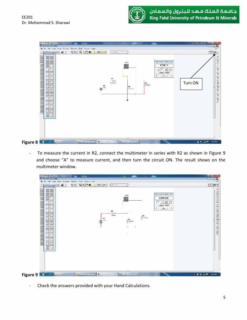
- To measure the current in R2, connect the multimeter in series with R2 as shown in Figure 9 and choose “A” to measure current, and then turn the circuit ON. The result shows on the multimeter window.
Figure 9
- Check the answers provided with your Hand Calculations.
Turn ON

EE201 Dr. Mohammad S. Sharawi
6
- These simulations are considered under “DC Analysis”. - Multisim can perform “Transient Analysis” that considered continuous time signals, and “AC
Analysis” that perform frequency domain analysis. - Another tutorial will be given for “Transient” and “AC” analysis types.