Multiplexer and De-Multiplexer - · PDF fileDepartment of Computer Science MUX and DeMUX The...
31
Department of Computer Science DCS COMSATS Institute of Information Technology Multiplexer and De-Multiplexer Rab Nawaz Khan Jadoon Lecturer COMSATS Lahore Pakistan Digital Logic and Computer Design
Transcript of Multiplexer and De-Multiplexer - · PDF fileDepartment of Computer Science MUX and DeMUX The...
Department of Computer Science
DCS
COMSATS Institute of Information Technology
Multiplexer and De-Multiplexer
Rab Nawaz Khan JadoonLecturer
COMSATS Lahore
Pakistan
Digital Logic and Computer Design
Department of Computer Science
Data Selection Function
Two types of circuits that select data are the Multiplexer and the Demultiplexer.
Multiplexer (MUX), switches digital data from several input lines onto a single output line in a specified time sequence.
Multiplexer (MUX) can be represented by an electronic switch operation that sequentially connects each of the input lines to the output line.
2
Department of Computer Science
MUX and DeMUX
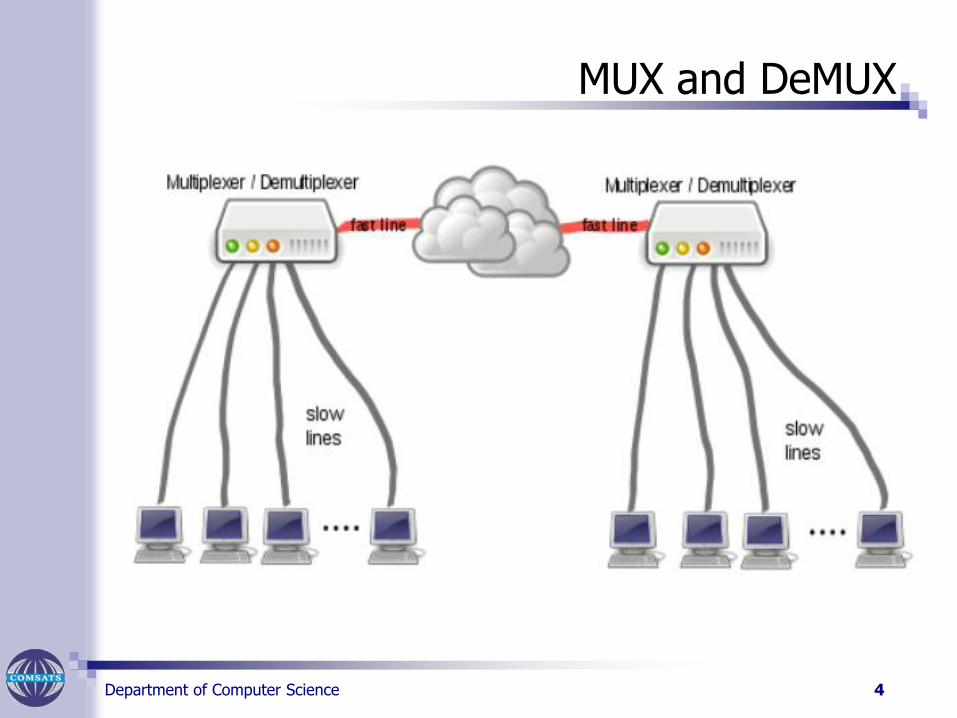
The Demultiplexer (Demux) is a logic circuit that switches digital data from one input line to several output lines in a specified time sequence.
Multiplexing and De-Multiplexing are used when data from several sources are to be transmitted over one line to a distant location and redistributed to several destinations.
3
Department of Computer Science
MUX and DeMUX
4
Department of Computer Science
MUX and De-MUX
5
Department of Computer Science
Multiplexer
A Multiplexer (MUX) is a device that allows digital information from several sources to be routed onto a single line for transmission over that line to a common destination.
The basic multiplexer has several data-input lines and a single output line.
It also has data-select inputs. which permit digital data on anyone of the inputs to be switched to the output line.
Multiplexers are also known as data selectors.
6

Department of Computer Science
Multiplexer
A logic symbol for a 4-input multiplexer (MUX) is shown in Figure,
7
Department of Computer Science
Multiplexer
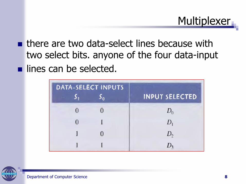
there are two data-select lines because with two select bits. anyone of the four data-input
lines can be selected.
8
Department of Computer Science
Logic Circuitry
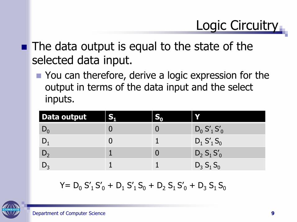
The data output is equal to the state of the selected data input.
You can therefore, derive a logic expression for the output in terms of the data input and the select inputs.
9
Data output S1 S0 Y
D0 0 0 D0 S’1 S’0
D1 0 1 D1 S’1 S0
D2 1 0 D2 S1 S’0
D3 1 1 D3 S1 S0
Y= D0 S’1 S’0 + D1 S’1 S0 + D2 S1 S’0 + D3 S1 S0
Department of Computer Science
Logic Circuitry
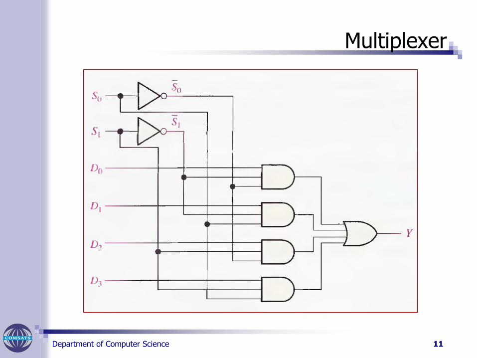
The implementation of this equation requires four 3-input AND gates, a 4-input OR gate, and two inverters to generate the complements of S1 and S0 .
Because data can be selected from anyone of the input lines, this circuit is also referred to as a data selector.
10
Department of Computer Science
Multiplexer
11
Department of Computer Science
Quadruple
Two or more multiplexers are enclosed with one IC package.
The selection and enable inputs in the multiple unit ICs may be common to the multiplexers.
On the next slide a quadruple 2 line to 1 line multiplexer IC is shown.
This type of IC is similar to IC type 74157.
It has 4 MUX, each capable of selecting one of two output lines.
12
Department of Computer Science
Quadruple
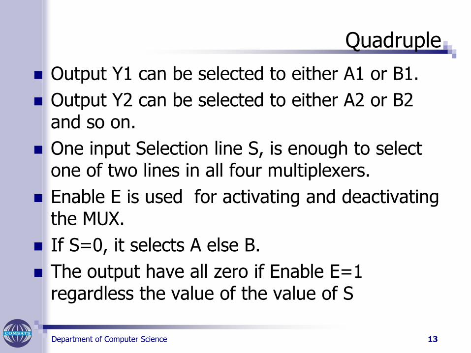
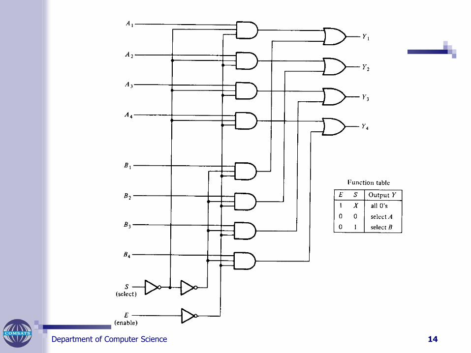
Output Y1 can be selected to either A1 or B1.
Output Y2 can be selected to either A2 or B2 and so on.
One input Selection line S, is enough to select one of two lines in all four multiplexers.
Enable E is used for activating and deactivating the MUX.
If S=0, it selects A else B.
The output have all zero if Enable E=1 regardless the value of the value of S
13
Department of Computer Science 14
Department of Computer Science 1515
Basic functionalities
A Demultiplexer (DEMUX) basically reverses the multiplexing function.
It takes digital information from one line and distributes it to a given number of output lines.
For this reason, the demultiplexer is also known as a data distributor.
Decoders can also be used as demultiplexers.
De-Multiplexer
Department of Computer Science 16
De-MultiplexerDecoder with Enable
Department of Computer Science
De-Multiplexer
17
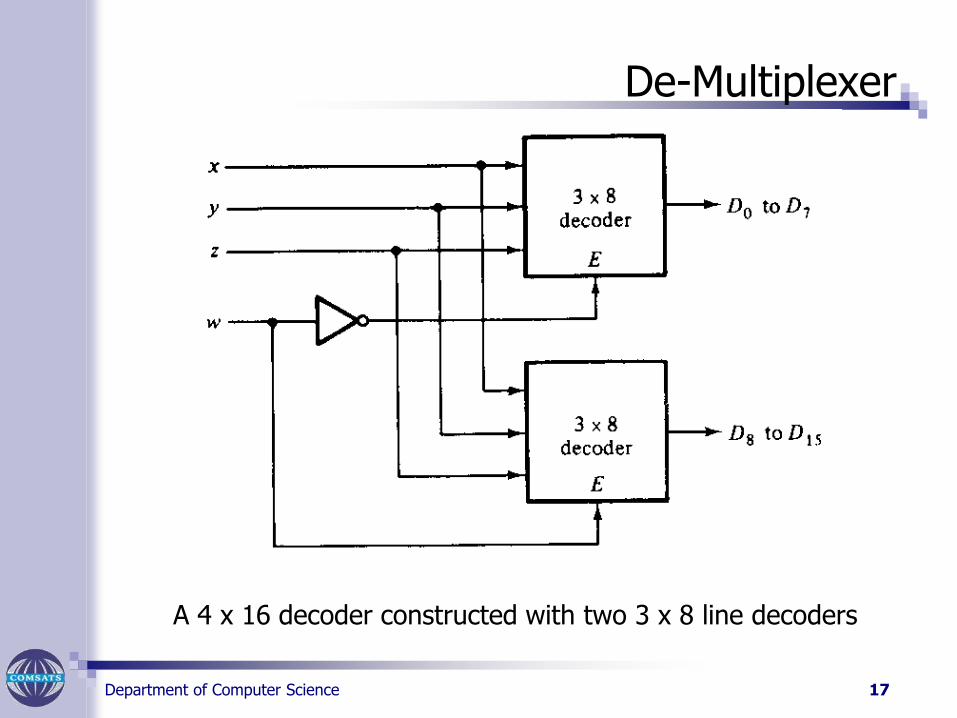
A 4 x 16 decoder constructed with two 3 x 8 line decoders
Department of Computer Science 18
De-Multiplexer
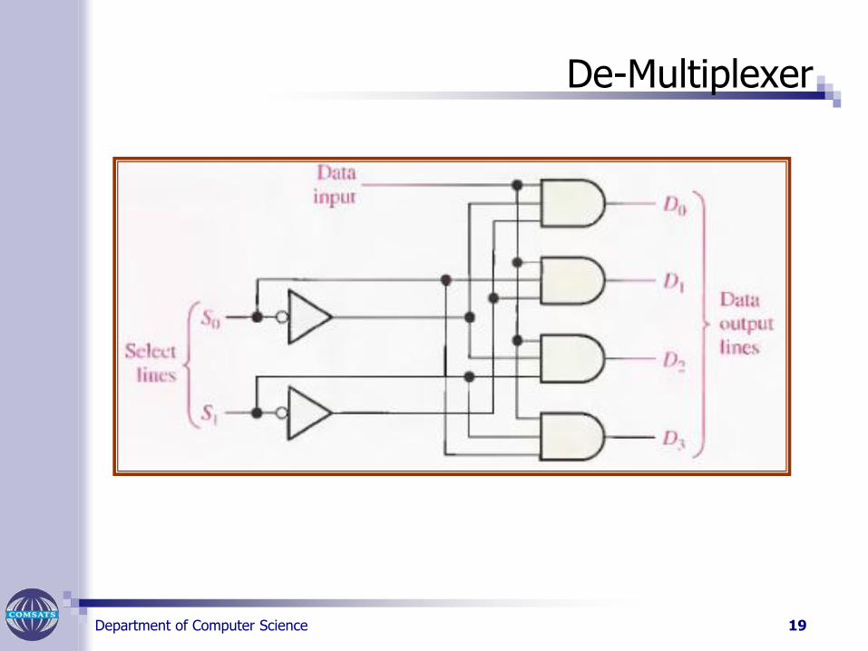
Figure on next slide shows 1-line-to-4-line Demultiplexer
(DEMUX) circuit.
The data-input line goes to all of the AND gates.
The two data-select lines enable only one gate at a time, and the data appearing on the data-input line will pass through the selected gate to the associated data-output line.
Department of Computer Science 19
De-Multiplexer
Department of Computer Science 20
De-Multiplexer
The De-Multiplexer
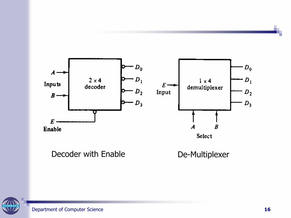
A decoder with an enable input can function as a demultiplexer.
A de multiplexer is a circuit that receives information on a single line and transmit it on to one of 2n
possible output lines.
The selection of a specific output line is controlled by the bit values of n selection lines.
The decoder can function as a demultiplexer if the E line is taken as data input line and lines A and B are taken as the selection lines.
Department of Computer Science
Procedure
Figure on slide 4, The data-input line goes to all of the AND gates.
The two data-select lines enable only one gate at a time, and the data appearing on the data-input line will pass through the selected gate to the associated data-output line.
21
Department of Computer Science 22
De-Multiplexer
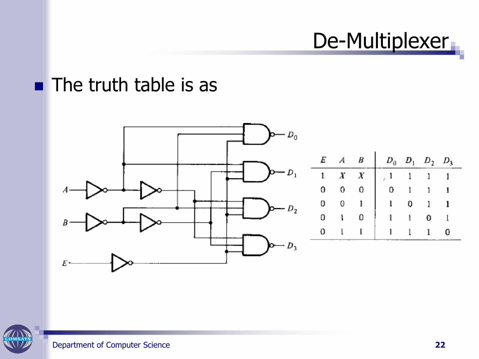
The truth table is as
Department of Computer Science
Boolean Function Implementation
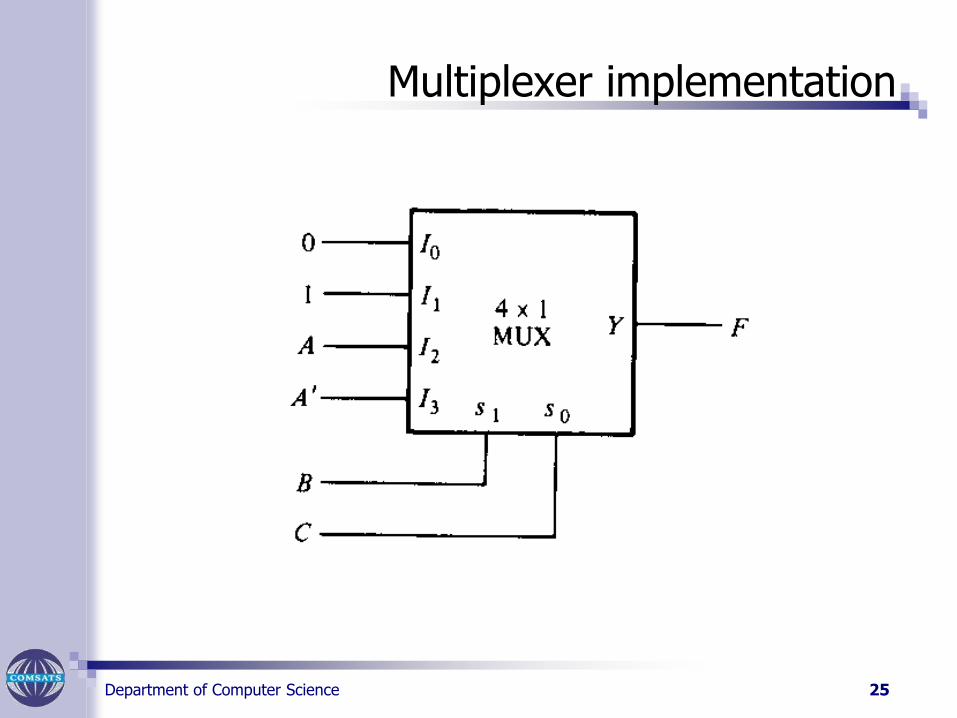
Decoder can be used to implement a booleanfunction with addition of one OR Gate.
In a multiplexer a full decoder with OR gate is present already.
The minterm out of the decoder to be chosen can be controlled with the input lines.
Example
F(A,B,C)= (1,3,5,6)
23

Department of Computer Science
Solution
24
Department of Computer Science
Multiplexer implementation
25
Department of Computer Science
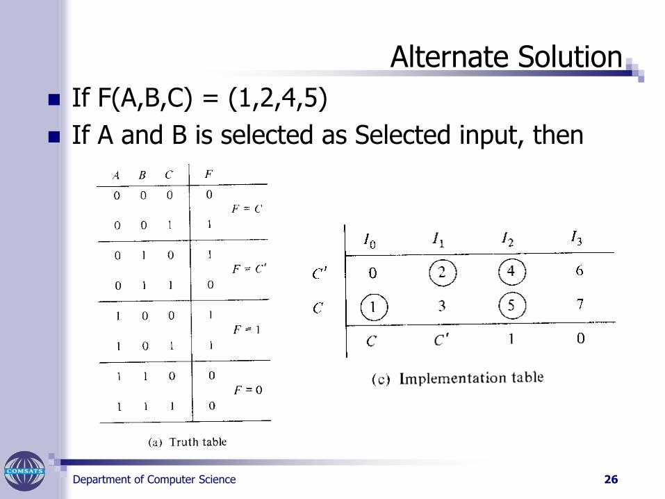
Alternate Solution
If F(A,B,C) = (1,2,4,5)
If A and B is selected as Selected input, then
26
Department of Computer Science
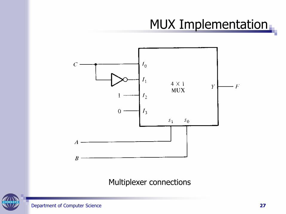
MUX Implementation
27
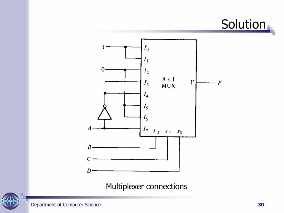
Multiplexer connections
Department of Computer Science
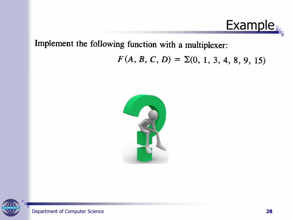
Example
28
Department of Computer Science
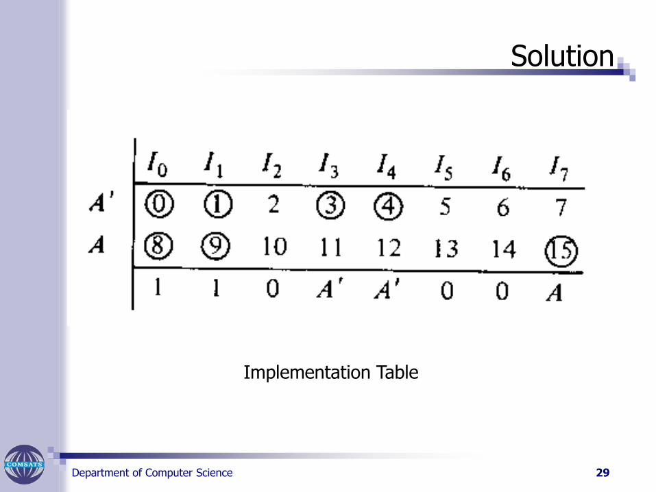
Solution
29
Implementation Table
Department of Computer Science
Solution
30
Multiplexer connections

Department of Computer Science 31