MULTIPLE PRESSURE TRANSDUCER TC Series Temperature … · gaskets : NBR or Viton rubber Sensor fill...
11
SC FEPA SA BARLAD Tel.: 0235/415990; 414660 S.G.:779M Str. Republicii nr. 316 Fax: 0235/421618; 413729 Rev.3 / 2010 CP. 731120 E-mail: [email protected] Pag. 1/11 MULTIPLE PRESSURE TRANSDUCER TC Series Temperature adapter Multivariate DISPLAYS TCM type Functional characteristics Working environment: gases, liquids, steam Input Signals: Differential fluid pressure: 0 ... 2000 mbar as coding static pressure (line) pressure absolute / relative: 0 ... 100 bar Temperature: Pt100 signal from heat resistant, W100 = 1.385 (α = 0.00385), 4 wires, at least grade B; temperature range: -40 ... 500 0C, in the baking dish. Output: digital signal bidirectional communication RS 485, MODBUS-RTU protocol, transmission rate 9600, no parity (N), 1bit, STOP transducer flow computer work associated with CDM type Maximum permissible static overpressure: 1.5 x maximum pressure static pressure sensor Coping measurement range limits: 1.1 x upper limit of the field of measuring the static pressure; 10 x upper limit of the differential pressure measuring range Power supply: 9 ... 30 VDC Power consumption: max. 0.1W Normal mechanical protection degree: IP65 according to EN 60 529 Explosive Protection: Ex d II CT6. The device is protected against reverse voltage and detection. The product can be provided (optional) local digital indicator display 2x16 characters successively every 5 seconds: differential pressure (DP), static pressure (PS) / temperature process (TP) and sensor name / no resistant (RTD error ), fixed temperature (T fixed) / 9600
Transcript of MULTIPLE PRESSURE TRANSDUCER TC Series Temperature … · gaskets : NBR or Viton rubber Sensor fill...

SC FEPA SA BARLAD Tel.: 0235/415990; 414660 S.G.:779M Str. Republicii nr. 316 Fax: 0235/421618; 413729 Rev.3 / 2010 CP. 731120 E-mail: [email protected] Pag. 1/11
MULTIPLE PRESSURE TRANSDUCER
TC Series Temperature adapter
Multivariate DISPLAYS TCM type
Functional characteristics Working environment: gases, liquids, steam Input Signals: Differential fluid pressure: 0 ... 2000 mbar as coding static pressure (line) pressure absolute / relative: 0 ... 100 bar Temperature: Pt100 signal from heat resistant, W100 = 1.385 (α = 0.00385), 4 wires, at least grade B; temperature range: -40 ... 500 0C, in the baking dish. Output: digital signal bidirectional communication RS 485, MODBUS-RTU protocol, transmission rate 9600, no parity (N), 1bit, STOP transducer flow computer work associated with CDM type Maximum permissible static overpressure: 1.5 x maximum pressure static pressure sensor Coping measurement range limits: 1.1 x upper limit of the field of measuring the static pressure; 10 x upper limit of the differential pressure measuring range Power supply: 9 ... 30 VDC Power consumption: max. 0.1W Normal mechanical protection degree: IP65 according to EN 60 529 Explosive Protection: Ex d II CT6. The device is protected against reverse voltage and detection. The product can be provided (optional) local digital indicator display 2x16 characters successively every 5 seconds: differential pressure (DP), static pressure (PS) / temperature process (TP) and sensor name / no resistant (RTD error ), fixed temperature (T fixed) / 9600
SC FEPA SA BARLAD Tel.: 0235/415990; 414660 S.G.:779M Str. Republicii nr. 316 Fax: 0235/421618; 413729 Rev.3 / 2010 CP. 731120 E-mail: [email protected] Pag. 2/11
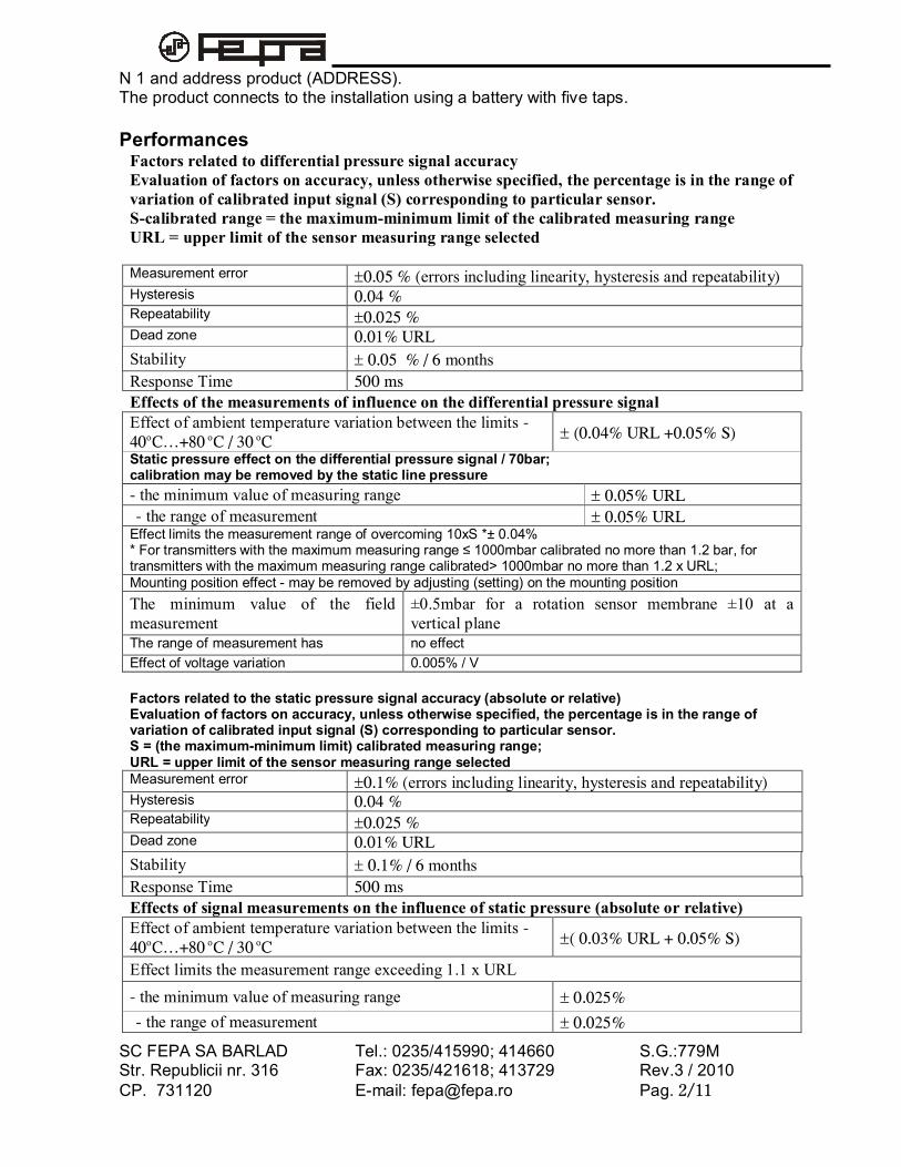
N 1 and address product (ADDRESS). The product connects to the installation using a battery with five taps. Performances
Factors related to differential pressure signal accuracy Evaluation of factors on accuracy, unless otherwise specified, the percentage is in the range of variation of calibrated input signal (S) corresponding to particular sensor. S-calibrated range = the maximum-minimum limit of the calibrated measuring range URL = upper limit of the sensor measuring range selected Measurement error 0.05 % (errors including linearity, hysteresis and repeatability) Hysteresis 0.04 % Repeatability 0.025 % Dead zone 0.01% URL Stability 0.05 % / 6 months Response Time 500 ms Effects of the measurements of influence on the differential pressure signal Effect of ambient temperature variation between the limits -40oC…+80 oC / 30 oC (0.04% URL +0.05% S)
Static pressure effect on the differential pressure signal / 70bar; calibration may be removed by the static line pressure - the minimum value of measuring range 0.05% URL
Asupra - the range of measurement 0.05% URL Effect limits the measurement range of overcoming 10xS *± 0.04% * For transmitters with the maximum measuring range ≤ 1000mbar calibrated no more than 1.2 bar, for transmitters with the maximum measuring range calibrated> 1000mbar no more than 1.2 x URL; Mounting position effect - may be removed by adjusting (setting) on the mounting position The minimum value of the field measurement
±0.5mbar for a rotation sensor membrane ±10 at a vertical plane
The range of measurement has no effect Effect of voltage variation 0.005% / V Factors related to the static pressure signal accuracy (absolute or relative) Evaluation of factors on accuracy, unless otherwise specified, the percentage is in the range of variation of calibrated input signal (S) corresponding to particular sensor. S = (the maximum-minimum limit) calibrated measuring range; URL = upper limit of the sensor measuring range selected Measurement error 0.1% (errors including linearity, hysteresis and repeatability) Hysteresis 0.04 % Repeatability 0.025 % Dead zone 0.01% URL Stability 0.1% / 6 months Response Time 500 ms Effects of signal measurements on the influence of static pressure (absolute or relative) Effect of ambient temperature variation between the limits -40oC…+80 oC / 30 oC ( 0.03% URL + 0.05% S)
Effect limits the measurement range exceeding 1.1 x URL
- the minimum value of measuring range 0.025%
Asupra - the range of measurement 0.025%

SC FEPA SA BARLAD Tel.: 0235/415990; 414660 S.G.:779M Str. Republicii nr. 316 Fax: 0235/421618; 413729 Rev.3 / 2010 CP. 731120 E-mail: [email protected] Pag. 3/11
Mounting position effect - may be removed by adjusting (setting) on the mounting position The minimum value of the field measurement
±0.5mbar for a rotation sensor membrane ±10 at a vertical plane
The range of measurement has no effect Effect of voltage variation 0,005%/V
Factors related to precision temperature signal Evaluation of precision factors refer only to the adapter and heat resistant to 100 does not contain errors, α = 0.00385 (W100 = 1.385), 4 wire, Tempered fall into Class B or higher. Measurement error 0.40C (errors including linearity, hysteresis, repeatability) Effect of ambient temperature variation, within -40oC …+80 oC : 0.3 OC/ 30OC Stability 0.3 0C /year Effect of voltage variation 0,005%/V
Response Time: 500 ms Physical Characteristics
Process connections the pressure
threaded 1 / 4 "NPT, connection via battery taps and nipples with male thread 1 / 4 "NPT, 1 / 2" NPT, G1 / 2 "- according to coding
Electrical connections and temperature sensor connection
IPE13.5 thread for cable gland d7.5, 9, 11, on both sides of the casing (base) adapter; Optional: 2 cable glands according to coding
Materials housing and adapter caps : The die-cast alloy - painted detector covers, connectors, plugs : Stainless steel AISI 316, 1.4541 plugs / pins purge : Stainless steel AISI 316, 1.4541 membrane isolation : AISI 316L AISI304L gaskets : NBR or Viton rubber Sensor fill fluid : Silicone oil screws : Galvanized carbon steel Weight (without options) : 40.3 kg;
Environmental conditions for use, storage, transport Operating Category SREN 60654-1: Cx class location. Climate Zone N STAS 6535-83 Ambient temperature limits in operation: -40 ° ... 80 ° C Note: ...- 40 ° -20 ° C does not display digital indicator. Measuring fluid temperature limits: -30 ° ... 80 ° C for direct connection into process -40 ° C ... 500 ° C through the process separators, the operating temperature pressure sensors: -40 ° ... 80 °. Relative Humidity: max. 100% of the Class C2 SREN 60 654 -1. Limits of temperature and humidity during storage and transportation: 60 654 -1 SREN class C2. Packaged transducers, temperature withstand accidental places to -65 oC to 80 oC and sudden variations of pressure from atmospheric pressure to the equivalent altitude of 10,000 m. Type of location for electronic transducer block intervention: B2 according to EN 60654-1 (temperature 30 OC 15 OC ... 85% maximum relative humidity).

SC FEPA SA BARLAD Tel.: 0235/415990; 414660 S.G.:779M Str. Republicii nr. 316 Fax: 0235/421618; 413729 Rev.3 / 2010 CP. 731120 E-mail: [email protected] Pag. 4/11
DIMENSIONS AND MOUNTING OPTIONS
IPE13
.5
Ø14
DP = 50 mbarPS = 6 bar
106±1 (fara presetupe conexiuni electrice)
HL
82
41.3±0.1conexiuni1/4"NPT
TP = xxx °CTA = xxx °C
Meniuri succesive
DP = xxx UM
PS = xxx UM
9600 N 1ADRESA=
EROARE RTDT FIXAT= xx°C
(*)- cand nu se monteaza
termorezistenta
(*)
Fig.1 Traductor multivariabila tip TCM -Forma, dimensiuni de gabarit, conexiuni
235±
5
LH
117±4 (se adauga 25 pe ambele parti,
spatiu desfacere capace)
Borna
impa
man
tare
IPE13
.5
Prese
tupe
PC8
pentru
cablu
cone
xiun
e alim
entare s
i se
mna
l
Prese
tupa
PC8
pentru c
ablu c
onex
iune
RTD(Pt100
)
Vedere fara presetupe
Vedere fara presetupe
150±10 (se mai adauga min.30 pe ambele
parti pentru montare-demontare cablu)
Cab
lu e
cran
at R
E-2Y(St)Y
v 2x
2x0.75
mm
2 (min),
Lmin=3
m; se
livreaz
a la c-da
impreu
na c
uterm
orez
istenta
Cab
lu e
cran
at m
in.2x2
x0.75m
m2 ,
Lmin=3
m; se
com
anda
sep
arat
M10x1.25/17
Baza se poate rotifata de detectorla 90°, 180°sau la-90°
NOTAPentruvariantele inconstructieantideflagranta,cablul trebuiesa fie certificatEx
54±0.2
Subans.baza
Ans.detector
A a b B
A B - +ALIM.RS485
Pt100
AB-+ALIM. RS485
AabBPt100
ecran cablu
ecran
cablu
Cablu conexiune recomandat:Cablu ecranatRE-2Y(St)Yv 2x2x0.75mm2
SCHEMA CONEXIUNI ELECTRICE TCM
Fig. 1. Multivariable transducer - the shape, dimensions, electrical connections

SC FEPA SA BARLAD Tel.: 0235/415990; 414660 S.G.:779M Str. Republicii nr. 316 Fax: 0235/421618; 413729 Rev.3 / 2010 CP. 731120 E-mail: [email protected] Pag. 5/11
IPE13.5
Ø14
DP =
50
mba
rPS =
6 b
ar
106±
1 (fa
ra p
rese
tupe
con
exiuni e
lectric
e)
HL 54
±0.2
82
41.3±0
.1
cone
xiun
i proc
es2x1
/4"N
PT
Fig. 2.
Trad
uctor multivariabila T
CM e
chipat cu
BR si term
orez
istenta
atas
ata
- Fo
rma
si d
imen
siun
i de
gab
arit
235±5
L
85±0
.2
M10
adanc. 13.5
H
cone
xiun
i pu
rjare
2x1/4"NPT
109±
0.3
VENT
VENT
ISOLA
TE
EGALISE
VENT
VENT
280±5
117±
4 (se
adau
ga 2
5 pe
ambe
le p
arti,
spatiu d
esface
re c
apac
e)
max
. 28
5 (cu
robine
tele d
esch
ise)
max
. 15
0
Borna
impa
man
tare
IPE13.5
Prese
tupe
PC8
pentru
cablu
cone
xiun
ealim
entare si se
mna
l
Prese
tupa
PC8
pentru
cablu
cone
xiun
eRTD(P
t100
)
Ved
ere
fara p
rese
tupe
Ved
ere
fara p
rese
tupe
150±
10 (
se m
ai ada
uga
min.30
pe a
mbe
le
parti pe
ntru m
ontare-dem
ontare cab
lu)
Fn
Øt
LiCab
lu E
x ec
rana
tRE-2Y(S
t)Yv
2x2x
0.75
mm
2 ,Lm
in=3
mTermorez
istenta
inca
rcas
a Ex
d IIC
, Pt100
,4
fire, W
100 =1
.385
,clas
a min. B
Dim
ensiun
i co
nform
coman
da
Cab
lu E
x ec
rana
tRE-2Y(S
t)Yv
2x2
x0.75m
m2 ,
Lmin=3m
; se
com
anda
sep
arat
Baterie cu
5robine
te tip B
R
ISOLA
TE
Garnitura B
R=2
buc
31.5
Baz
a se
poa
te roti
fata d
e de
tector
la 9
0°, 18
0°sa
u la-90°
NOTA
Pen
tru
varia
ntele
in con
structie
antid
eflagran
ta:
- ca
blul trebu
ie sa
fie c
ertificat E
x- term
orez
istenta
atas
ata
trebu
ie s
afie
cu
cutie
de
borne
in c
onstructie
simila
ra tradu
ctorului.

SC FEPA SA BARLAD Tel.: 0235/415990; 414660 S.G.:779M Str. Republicii nr. 316 Fax: 0235/421618; 413729 Rev.3 / 2010 CP. 731120 E-mail: [email protected] Pag. 6/11
82
IPE13.5
A
Ved
ere
din
A
Brake
t 1
buc
Bratara
1 b
uc
Saiba
A8
2 b
ucPiulita
M8
2 b
ucSup
ort BR
1 b
uc
Tea
va 2
"ve
rticala
96±5
max
.200
DP =
50
mba
rPS =
6 b
ar HL 54
±0.2
VENT
VENT
102.50
TCM
Surub
M10
x40
2 b
uc
Fig.3a
Tradu
ctor m
ultivariabila T
CM
- fix
are
pe tea
va 2
" ve
rticala
Saiba
plata A
10 2
buc

SC FEPA SA BARLAD Tel.: 0235/415990; 414660 S.G.:779M Str. Republicii nr. 316 Fax: 0235/421618; 413729 Rev.3 / 2010 CP. 731120 E-mail: [email protected] Pag. 7/11
82
IPE13
.5
DP = 50 mbarPS = 6 bar
HL
54±0.2
VENT
VENT
Teava 2"orizontala
Fig.3b Traductor multivariabila TCM- fixare pe teava 2" orizontala
Baza se poate rotifata de detectorla 90°, 180°sau la-90°
82
IPE13
.5
Teava 2"orizontala
DP = 50 mbarPS = 6 bar
HL
54±0.2
VENT
VENT
Fig.3c Traductor multivariabila TCM- fixare pe teava 2" orizontala

SC FEPA SA BARLAD Tel.: 0235/415990; 414660 S.G.:779M Str. Republicii nr. 316 Fax: 0235/421618; 413729 Rev.3 / 2010 CP. 731120 E-mail: [email protected] Pag. 8/11
Ø tub
Niplu mobil
Opritor
Fn
Cutie de borne Flansa mobila
Ln (lungime nominala)
Ø70
3x Ø
7ec
hidist.
Ø55
10
Li (lungime imersie)
Li
3x Ø
7ec
hidist.
Ø55
Ø70
Fig.4 Termorezistenta - variante, dimensiuni
Fig.5 TEACA CU FLANSA
Fig.6 TEACA CU FILET
Fn
Cm
10-3
10-3
Li (lungime imersie)
Li (lungime imersie)

SC FEPA SA BARLAD Tel.: 0235/415990; 414660 S.G.:779M Str. Republicii nr. 316 Fax: 0235/421618; 413729 Rev.3 / 2010 CP. 731120 E-mail: [email protected] Pag. 9/11
ENCODE
Model TCM X XX XX (...) X X X X X Description level coding
Level code a b c d e f g h i
a. Degree of mechanical protection and explosive A. IP65 sealed housing, according to SR EN 60529, Al alloy.
B. Ex-explosive protection by flameproof enclosure according to EN 60079-1 DII CT6, Al alloy, (in waterproof IP65 case)
b. Material detector caps, connectors / plugs, pins, belts / membrane isolation. 02 AISI316 / AISI316 / AISI304 or equivalent 03 1.4541 / 1.4541 / AISI304 or equivalent xx special orders, specify the material
c. The maximum differential pressure-measuring range (URL) and measuring range (s) that can be calibrated sensor performance storage - see note 1
The maximum measuring range of sensor URL (mbar) S calibrated measuring range (mbar)
03 75 25 ... 75 04 400 75 ... 400 05 1000 400 ...1000 06 2000 700 ... 2000 0S 75 to request the specific 70000mbar dp max.
d. Static pressure sensor type A Absolute pressure sensor
R Relative pressure sensor
e. The maximum static pressure-measurement range (URL) and measuring range (s) that can be calibrated sensor performance storage - see note 1
The maximum measuring range of sensor URL (mbar) S calibrated measuring range (mbar)
10 10 3.5 ... 10
25 25 10 ... 25
64 70 25 ... 70
100 100 50 ... 100 (.../.../...)Calibrated measuring range limits
Specify limits on the calibrated measuring range differential pressure and the chosen unit / calibrated measuring range limits the static pressure and the chosen unit / calibrated within the temperature measuring range Ex: (0...2500mmH2O/0...35 bar /-40o to 100oC ...)
e. Lining material in contact with the measuring 1 NBR rubber, or equivalent.
2 Viton Rubber
f. Pressure-type connector in the process - the process connection is made only by means of battery with 5 (or 3) type taps BR - Figure 2 - Specify the battery connection nipples
0 Internal thread 1 / 4 "NPT 1 Nipples male thread 1 / 4 "NPT 2 Nipples male thread 1 / 2 "NPT 3 Nipples male thread G1 / 2 " 4 Internally threaded nipples 1 / 2 "NPT
ENCODE - continued

SC FEPA SA BARLAD Tel.: 0235/415990; 414660 S.G.:779M Str. Republicii nr. 316 Fax: 0235/421618; 413729 Rev.3 / 2010 CP. 731120 E-mail: [email protected] Pag. 10/11
Level code a b c d e f g h i Description level coding
g. Mounting in the installation - the transducer is mounted in the system only through taps battery grip includes support
O Battery mounting valve type BR h. Options - can control several features compatible
BR Battery with 5 taps, battery code is chosen according to SG 552, see note 3.
PC8 Example 2 glands of stainless steel with a set of seals for cable with outer diameter of 7.5, 9, 11; See Note 2
M Digital Indicator, 4x16 characters
T Tempered For 100, W100 = 1385, 4 wires attached Is chosen according to the following coding
W Key and opened the lids tightly. Note: 1) For every measurement (S) smaller errors are amplified to the max. URL/3S. 2) Transducer housing is provided with two connections IPE13.5 for cable gland, cable gland must be ordered separately through FP8 option, no option (FP8) products are delivered with protective plastic caps on electrical connections. 3) The transducer is mounted in the system only through one of these two batteries. ENCODE baking Tempered Type: Pt100, W100 = 1385, 4-wire, protective tube material: stainless steel; Protection tube diameter: 10mm, on request and offer other sizes required.
Model TTR xx x xx xx x X X X Description level coding
Level code a b c d e f g h
a. Cable length between transducer and Tempered (Shipped - shielded cable, Ex 2x2x0.75mm2)
00 Tempered without cable 30 TTR-transducer cable length = 3 m 70 TTR-transducer cable length = 7.5 m xx TTR-transducer cable length= on request (specify length in meters, between brackets) b. Tempered Class A Class A (I) B Class B (II) c. Range of temperature 01 - 50 ... 150 OC 02 - 50 ... 250 OC 03 - 50 ... 500 OC d. Nominal protection tube 25 250mm 50 500mm 00 upon request, specified nominal length
ENCODE baking - continued Model TTR xx x xx xx x X X X
Description level coding Level code a b c d e f g h
e. fixture
1 Mobile nipple G1 / 2 "

SC FEPA SA BARLAD Tel.: 0235/415990; 414660 S.G.:779M Str. Republicii nr. 316 Fax: 0235/421618; 413729 Rev.3 / 2010 CP. 731120 E-mail: [email protected] Pag. 11/11
2 mobile flange
o on request - please specify type and size
f. Immersion length (depending on the nominal length)
Nominal Length (mm)
250 500 Immersion Length (mm) 1 - 400
2 - 350
3 - 300
4 - 280
5 - 260
6 - 250
7 150 200
8 110 110
g. sheath mount installation 0 sheath without mounting in the installation
1 Stainless steel mounting sleeve 2 carbon steel mounting sleeve h. Dimensions sheath connection 0 without sheath Sheath with a flange (Figure 5) 2 welded sheath) Threaded outer sheath 3 3 / 4 "NPT (fig.6
0 * threaded outer sheath on request (specify thread (Cm - fig.6)