Multifunctional Gate Box MGB - Twittlebit.comeshop.twittlebit.com/Asset/MGB.pdfRobust metal parts...
17
More than safety. Multifunctional Gate Box MGB MGB
Transcript of Multifunctional Gate Box MGB - Twittlebit.comeshop.twittlebit.com/Asset/MGB.pdfRobust metal parts...

More than safety.
Multifunctional Gate Box
MGBMGB

2
Quality, reliability, precision
Quality, reliability and precision are thehallmarks of our corporate philosophy.They represent concepts and valuesto which we feel totally committed. At EUCHNER, quality means that allour employees take personal respon-sibility for the company as a wholeand, in particular, for their own field ofwork. This individual commitment toperfection results in products whichare ideally tailored to the customers’needs and the requirements of themarket. After all: our customers andtheir needs are the focus of all ourefforts. Through efficient and effectiveuse of resources, the promotion ofpersonal initiative and courage in find-ing unusual solutions to the benefit ofour customers, we ensure a high levelof customer satisfaction. We familiar-ize ourselves with their needs, require-ments and products and we learnfrom the experiences of our cus-tomers’ own customers.
EUCHNER – More than safety.
Quality – made by EUCHNER
More than safety.Around the world – the Swabianspecialists in motion sequencecontrol for mechanical and sys-tems engineering.
EUCHNER’s history began in 1940 withthe establishment of an engineeringoffice by Emil Euchner. Since thattime, EUCHNER has been involved inthe design and development of switch-gear for controlling a wide variety ofmotion sequences in mechanical andsystems engineering. In 1953, EmilEuchner founded EUCHNER + Co., amilestone in the company’s history. In1952, he developed the first multiplelimit switch – to this day a symbol ofthe enterprising spirit of this family-owned company.
Automation – Safety – ManMachine
Today, our products range fromelectromechanical and electroniccomponents to complex system solu-tions. With this wide range of productswe can provide the necessary tech-nologies to offer the right solution forspecial requirements – regardless ofwhether these relate to reliable andprecise positioning or to componentsand systems for safety engineering inthe automation sector.EUCHNER products are sold through aworld-wide sales network of compe-tent partners. With our closeness tothe customer and the guarantee ofreliable solutions throughout theglobe, we enjoy the confidence of cus-tomers all over the world.
Emil Euchner, the company’s founder andinventor of the multiple
limit switch, circa 1928.
Safety

4
General
Subject to technical modifications; no responsibility is accepted for the accuracy of this information.
A handle on the future
The MGB (Multifunctional Gate Box) is a unique interlocking or guard locking system for the protection of safety doors on machines and systems.
The MGB offers that little bit more: it is more than a safety switch, more than a bolt, and offers a lot more functionality!
A system that can grow with your needsEven the basic system comprising handle module and evaluation module (as interlocking module or locking module) includes numerous func-tions.Whether interlocking, guard locking, escape release or other functions such as buttons for start/stop, emergency stop, etc. – The MGB meets all your requirements for safety-related applications.
And if your needs grow, the MGB system grows with them. Due to the sophisticated modular design, the evaluation module can quickly become a small operator panel.
Be certain of compliance with new standardsPerformance Level e in accordance with EN ISO 13849-1 or SIL3 in ac-cordance with EN 62061 – even with the basic system you can comply with all these requirements. Also the requirements of EN 1088 for protection against tampering are met automatically, as each evaluation module is permanently assigned to a handle module.
Safety remains the most important goalAre you locked in inside the danger area? The optional escape release is intuitive to operate! Whether in the event of a power failure or active guard locking – the red door handle is simply pressed down to leave the danger area quickly.For protection when working in the danger area you can block the bolt tongue using up to 3 padlocks in the integrated lockout bar. Unintentional activation of the interlocking/guard locking is prevented.
Everything at a glanceThe LED display continuously provides you with all important system information. Diagnostics and status check at a glance!
Solid door stopA mechanical door stop is permanently integrated into the evaluation module. There is a marking on the stop that makes adjustment easier.
Evaluation module (as interlocking module or locking module)
Space for ideas...Controls and indicators in the housing cover make the MGB an all-rounder. With start button, enable and emergency stop or other functions, the evaluation module becomes a small control terminal.
Mechanical releaseFor releasing the guard lockinge.g. in case of a power failure.
PL!/C"#. 4$%t& '()#*n! +, !!!
G-n-r*(st.l-r"nc/
S"v/ 0%m!
"n1 2*n3!

5
General
Subject to technical modifications; no responsibility is accepted for the accuracy of this information.
Easy to mount and sophisticated designAll MGB modules are optimized for use on fences made of aluminum profiles or steel frames. The MGB is equally suitable for doors hinged on the left or right. Both mounting and changing the actuating direction can be undertaken particularly quickly and easily.
The adjustment of safety doors in fences changes over time. With ± 4 mm tolerance in the x direction as well as ± 5 mm in the z direction, the MGB is right there where the problem starts. Nevertheless, if a safety door should be even more out of adjustment, the large funnel in the evaluation module "catches" the bolt tongue and guides it into the center position. Bolt tongue, bolt guide and insertion funnel will also withstand occasional slamming of the door. Robust metal parts protect the MGB against this problem as well. To prevent injuries, the bolt tongue remains retracted with the door open.
You always have an overviewFour built-in LEDs continuously provide all the necessary system informa-tion: power supply available, door closed, bolt tongue inserted, guard locking activated, diagnostics messages – everything can be seen clearly at a glance. This information is of course also available to the control system.
The advantages of the Multifunctional Gate Box MGB
Optimized for mounting on profiles from 30 - 50 mm
Tolerance ± 4 mm in x direction, ± 5 mm in z direction
Locking force 2000 N
The MGB withstands forces amounting up to 300 Joule
Optional escape release with door handle
Optional buttons and indicators can be integrated directly into the housing
Stable metal stop prevents damage with bolt tongue extended
Marking on the evaluation module as adjustment aid
The actuating direction is easy to change without disassembly
Hidden mounting holes with slots and metal mounting surfaces
Housing material made of high quality, reinforced plastic
Escape release can also be used on doors with double rebate
Door handle includedThe MGB has a robust door handle that can be rotated in 90° steps – to suit the installation.
Escape release (optional)The safety system MGB can be expanded with an escape release module. The escape release enables people accidentally shut in to open the guard locked door from the danger area.
Lockout barThe bolt tongue is blocked for cleaning and service with max. 3 locks.
Intelligent bolt tongueThe bolt tongue is reliably detected by transponder as soon as it is inserted in the evaluation module.
Escape release module
Handle module
Fl4%5l!c678%n"0i*9s(:%# ;)t-<)
V-ry )%7=l!2*(90%ng
R">i1 /c"p!
Op-?
S"f,y @r*vide1%? "ny )%0u"0i*?

6
System Overview Safety System MGB
Subject to technical modifications; no responsibility is accepted for the accuracy of this information.
Evaluation modules
Interlocking moduleWithout controls
(see page 12)
Interlocking moduleWith EMERGENCY STOP device and2 illuminated buttons
(see page 13)
Locking moduleWithout controls
(see page 14)
Locking moduleWith EMERGENCY STOP device and2 illuminated buttons
(see page 15)
Cat.4
PLe
Cat.4
PLe
Cat.4
PLe
Cat.4
PLe
Explanation of symbolsSafety category/guard locking
Cat.4
PLe
Suitable up to category 4 according to EN 954-1 and Performance Level PLe according to EN ISO 13849-1
Guard locking for personal protection

7
System Overview Safety System MGB
Subject to technical modifications; no responsibility is accepted for the accuracy of this information.
Handle module
Handle moduleWith lockout bar
(see page 16)
Escape release module
Escape release moduleWith red handle
(see page 17)

9
Safety System MGB
Subject to technical modifications; no responsibility is accepted for the accuracy of this information.
Complete MGB sets in overview
Ordering table
Order no./item
Evaluation modules
Inte
rlock
ing
mod
ule
(w
ithou
t gua
rd lo
ckin
g,
see
page
12
and
13)
Lock
ing
mod
ule
(m
echa
nica
l gua
rd lo
ckin
g,
see
page
14
and
15)
Lock
ing
mod
ule
(e
lect
rical
gua
rd lo
ckin
g,
see
page
14
and
15)
Additional functions
Han
dle
mod
ule
100
464
MGB
-H-A
A1A1
-R-1
0046
4(s
ee p
age
16)
Esca
pe r
elea
se m
odul
e10
0 46
5M
GB-E
-A-1
0046
5(s
ee p
age
17)
2 ill
umin
ated
but
tons
(S2
and
S3, i
n th
e
eval
uatio
n m
odul
e)
EMER
GEN
CY
STO
P de
vice
(S1,
in th
e ev
alua
tion
mod
ule)
105 778MGB-L0H-AR-R-105778
Cat.4
PLe
105 779MGB-L0H-AR-R-105779
Cat.4
PLe
105 780MGB-L0HE-AR-R-105780
Cat.4
PLe
105 781MGB-L0HE-AR-R-105781
Cat.4
PLe
105 782MGB-L1H-AR-R-105782
Cat.4
PLe
105 783MGB-L1H-AR-R-105783
Cat.4
PLe
105 784MGB-L1HE-AR-R-105784
Cat.4
PLe
105 785MGB-L1HE-AR-R-105785
Cat.4
PLe
105 786MGB-L2H-AR-R-105786
Cat.4
PLe
105 787MGB-L2H-AR-R-105787
Cat.4
PLe
105 788MGB-L2HE-AR-R-105788
Cat.4
PLe
105 789MGB-L2HE-AR-R-105789
Cat.4
PLe
Description of the individual modules starting from page 12.
Key to symbols Included in the set
Button positions
S1L1
S2L2S3L3
S4L4

10
Safety System MGB
Subject to technical modifications; no responsibility is accepted for the accuracy of this information.
Evaluation modules
Guard locking Order no./item
2 illuminated buttons(S2 and S3, in the evaluation module)
EMERGENCY STOP device(S1, in the evaluation module)
Without
105 331MGB-L0-AR-AA1A1-M-105331
106 106MGB-L0-AR-AA2A1-M-106106
Mechanical
104 302MGB-L1-AR-AA1A1-M-104302
105 328MGB-L1-AR-AA2A1-M-105328
Electrical
104 303MGB-L2-AR-AA1A1-M-104303
105 797MGB-L2-AR-AA2A1-M-105797
Handle module
Order no./item Type
100 464MGB-H-AA1A1-R-100464 With locking arm, black housing with red cover
Escape release
Order no./item Type
100 465MGB-E-A-100465 Red handle
Key to symbols Available functions
Button positions
S1L1
S2L2S3L3
S4L4
Individual MGB modules in overview

11
Safety System MGB
Subject to technical modifications; no responsibility is accepted for the accuracy of this information.
Right-angle alignment of the escape release axis
Installation example
4x M6
2x M6
Fastening material not included!
Cut-out for escape release
46 89,4
6,3
15
15,410
30,35
10
6,2
8
35 11
6,5
86
92,5
77,5
16,5
24,5
68
Hole pattern Evaluation module Handle module

12
Safety System MGB
Subject to technical modifications; no responsibility is accepted for the accuracy of this information.
111
114
OPEN
CLOS
ED
1540 40
83
113,5 110
155,3 1304
9340
5172
19,2
M20x1,5 (4x)
289,3
DC 24 V DC 24 V
(Aux Pwr)
SafetyoutputsSafety inputs
Reset
UAUB IA OAIB OB0V 0V
MGB-L0-AR...
MonitoringoutputsO1 O2 O3 O4RST
Dimension drawing (Diagram shows door hinged on the right)
Block diagram
Solid door stopLED display2 buttons optionalEMERGENCY STOP device optional
Door stopA mechanical door stop is permanently integrated into the evaluation module MGB-L0... There is a marking on the stop that makes adjustment easier.
LED displayThe LED display indicates all important system and status information.
Buttons (optional)S2 1 NO contact, yellow, illuminatedS3 1 NO contact, white, illuminated
EMERGENCY STOP device (optional)S1 2 positively driven contacts, EMER-
GENCY STOP with turn-to-reset, non-illuminated
Monitoring outputsO1 Door positionO2 Bolt positionO3 Not usedO4 Diagnostic
Ordering guide See page 9 and 10
Technical data See page 18
Interlocking module MGB-L0...Without controls
Interlocking module MGB-L0...
Series Guard locking Type Order no./item
MGB-L0... Without Without controls 105 331MGB-L0-AR-AA1A1-M-105331
Ordering table
LED display
Cat.4
PLe

13
Safety System MGB
Subject to technical modifications; no responsibility is accepted for the accuracy of this information.
+
S1L1
S2L2S3L3
S4L4
DC 24 V DC 24 V
(Aux Pwr)
SafetyoutputsSafety inputs
Reset
UAUB IA OA
S1.1 S1.2 S1.3 S1.4
IB OB0V 0V S2 S3 L2 L3
MGB-L0-AR...
MonitoringoutputsO1 O2 O3 O4RST
111
114
OPEN
CLOS
ED
1540 40
83
114 110
155,3 1304
9340
<51>
72,5
19,2 M20x1,5 (4x)
289,3
1033
,240
33,5
Dimension drawing (Diagram shows door hinged on the right)
Block diagram
Interlocking module MGB-L0...With 2 buttons and EMERGENCY STOP device
Series Guard locking Type Order no./item
MGB-L0... Without With 2 buttons and EMERGENCY STOP device
106 106MGB-L0-AR-AA2A1-M-106106
Ordering table
LED display
S3 White button
S1 EMERGENCY STOP
S2Yellowbutton
Cat.4
PLe

14
Safety System MGB
Subject to technical modifications; no responsibility is accepted for the accuracy of this information.
Guard lockingSolid door stopMechanical releaseLED display2 buttons optionalEMERGENCY STOP device optional
Door stopA mechanical door stop is permanently integrated into the evaluation module MGB-L1.../MGB-L2... There is a marking on the stop that makes adjust-ment easier.
Mechanical releaseFor releasing the guard locking, e.g. in case of a power failure.
LED displayThe LED display indicates all important system and status information.
Buttons (optional)S2 1 NO contact, yellow, illuminatedS3 1 NO contact, white, illuminated
EMERGENCY STOP device (optional)S1 2 positively driven contacts, EMER-
GENCY STOP with turn-to-reset, non-illuminated
Guard locking typesMGB-L1... The locking arm is held in the
locked position by spring force and is unlocked by solenoid force (closed-circuit current principle).
MGB-L2... The locking arm is held in the locked position by solenoid force and is unlocked by spring force when the solenoid is switched off (open-circuit current principle).
Monitoring outputsO1 Door positionO2 Bolt positionO3 Position of the guard lockingO4 Diagnostic output
Ordering guide See page 9 and 10
Technical data See page 18
Locking module MGB-L1.../MGB-L2...Without controls
Locking module MGB-L1.../MGB-L2...
111
114
OPEN
CLOS
ED
1540 40
83
113,5 110
155,3 1304
9340
5172
19,2
M20x1,5 (4x)
289,3
DC 24 V DC 24 VSafetyoutputsSafety inputs
Reset
UCMUAUB IA OAIB OB0V 0V
Guardlocking
MGB-L1-AR... / MGB-L2-AR...
MonitoringoutputsO1 O2 O3 O4RST
(Aux Pwr)
Dimension drawing (Diagram shows door hinged on the right)
Block diagram
Series Guard locking Type Order no./item
MGB-L1... Mechanical Without controls 104 302MGB-L1-AR-AA1A1-M-104302
MGB-L2... Electrical Without controls 104 303MGB-L2-AR-AA1A1-M-104303
Ordering table
LED display Mechanical release
Cat.4
PLe

15
Safety System MGB
Subject to technical modifications; no responsibility is accepted for the accuracy of this information.
Locking module MGB-L1.../MGB-L2...With 2 buttons and EMERGENCY STOP device
+
S1L1
S2L2S3L3
S4L4
DC 24 V DC 24 VSafetyoutputsSafety inputs
Reset
UCMUAUB IA OA
S1.1 S1.2 S1.3 S1.4
IB OB0V 0V S2 S3 L2 L3
Guardlocking
MGB-L1-AR... / MGB-L2-AR...
MonitoringoutputsO1 O2 O3 O4RST
(Aux Pwr)
Block diagram
Series Guard locking Type Order no./item
MGB-L1... Mechanical With 2 buttons and EMERGENCY STOP device
105 328MGB-L1-AR-AA2A1-M-105328
MGB-L2... Electrical With 2 buttons and EMERGENCY STOP device
105 797MGB-L2-AR-AA2A1-M-105797
Ordering table
111
114
OPEN
CLOS
ED
1540 40
83
114 110
155,3 1304
9340
<51>
72,5
19,2 M20x1,5 (4x)
289,3
1033
,240
33,5
Dimension drawing (Diagram shows door hinged on the right)
LED display
Mechanical releaseS3
White button
S1 EMERGENCY STOP
S2Buttonyellow
Cat.4
PLe

16
Safety System MGB
Subject to technical modifications; no responsibility is accepted for the accuracy of this information.
111
114
OPEN
CLOS
ED
1540 40
83
113,5 110
155,3 1304
9340
5172
19,2
M20x1,5 (4x)
289,3
Dimension drawing (Diagram shows door hinged on the right)
Intelligent bolt tongueLockout barDoor handle
Bolt tongueThe bolt tongue is reliably detected by tran-sponderas soon as it is inserted in the evaluation mod-ule.
Lockout barThe bolt tongue can be blocked for cleaning and service with max. 3 locks.
Door handleTo suit all installations, the MGB has a robust door handle that can be rotated in 90° steps.The actuating direction can be changed for doors hinged on the left and on the right.
Handle module MGB-H-...
Handle module MGB-H-...
Ordering guide See page 9 and 10
1
2
3
4
Door handle Locking pins for housing cover and handle adjustment Lockout bar Bolt tongue
Series Type Order no./item
MGB-H... With lockout bar, black housing with red cover 100 464MGB-H-AA1A1-R-100464
Ordering table
Lockout bar
17
Safety System MGB
Subject to technical modifications; no responsibility is accepted for the accuracy of this information.
111
114
OPEN
CLOS
ED
1540 40
83
113,5 110
155,3 1304
9340
5172
19,2
M20x1,5 (4x)
289,3
83
Dimension drawing (Diagram shows door hinged on the right)
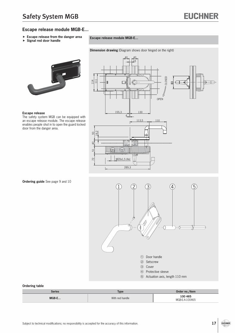
Escape release from the danger areaSignal red door handle
Escape releaseThe safety system MGB can be equipped with an escape release module. The escape release enables people shut in to open the guard locked door from the danger area.
Escape release module MGB-E...
Escape release module MGB-E...
Ordering guide See page 9 and 10
1 2 3 4 5
Door handle Setscrew Cover Protective sleeve Actuation axis, length 110 mm
Series Type Order no./item
MGB-E... With red handle 100 465MGB-E-A-100465
Ordering table
18
Safety System MGB
Subject to technical modifications; no responsibility is accepted for the accuracy of this information.
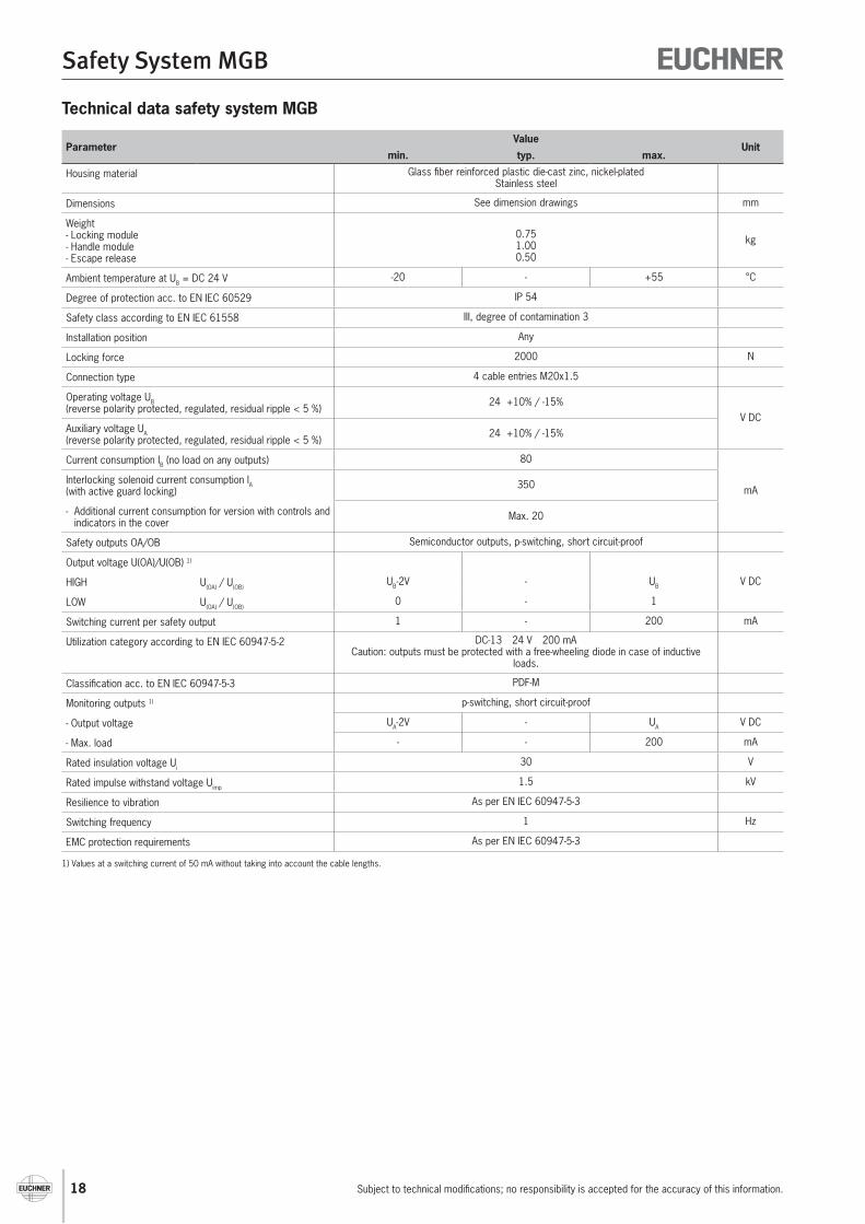
Technical data safety system MGB
ParameterValue
Unitmin. typ. max.
Housing material Glass fiber reinforced plastic die-cast zinc, nickel-platedStainless steel
Dimensions See dimension drawings mm
Weight- Locking module- Handle module- Escape release
0.751.000.50
kg
Ambient temperature at UB = DC 24 V -20 - +55 °C
Degree of protection acc. to EN IEC 60529 IP 54
Safety class according to EN IEC 61558 III, degree of contamination 3
Installation position Any
Locking force 2000 N
Connection type 4 cable entries M20x1.5
Operating voltage UB (reverse polarity protected, regulated, residual ripple < 5 %)
24 +10% / -15%V DC
Auxiliary voltage UA (reverse polarity protected, regulated, residual ripple < 5 %)
24 +10% / -15%
Current consumption IB (no load on any outputs) 80
mAInterlocking solenoid current consumption IA (with active guard locking)
350
- Additional current consumption for version with controls and indicators in the cover
Max. 20
Safety outputs OA/OB Semiconductor outputs, p-switching, short circuit-proof
Output voltage U(OA)/U(OB) 1)
V DCHIGH U(OA) / U(OB)UB-2V - UB
LOW U(OA) / U(OB)0 - 1
Switching current per safety output 1 - 200 mA
Utilization category according to EN IEC 60947-5-2 DC-13 24 V 200 mA Caution: outputs must be protected with a free-wheeling diode in case of inductive
loads.
Classification acc. to EN IEC 60947-5-3 PDF-M
Monitoring outputs 1) p-switching, short circuit-proof
- Output voltage UA-2V - UA V DC
- Max. load - - 200 mA
Rated insulation voltage Ui30 V
Rated impulse withstand voltage Uimp1.5 kV
Resilience to vibration As per EN IEC 60947-5-3
Switching frequency 1 Hz
EMC protection requirements As per EN IEC 60947-5-3
1) Values at a switching current of 50 mA without taking into account the cable lengths.

19
Safety System MGB
Subject to technical modifications; no responsibility is accepted for the accuracy of this information.
Important: Detailed information on the safety system MGB is available in the system manual for the related evaluation module. The system manual is available at www.euchner.de.
Separate operation
Operation in a CES-AR switch chain
Connection examples
24V
GND
-F1
U BX5
.6
0VX5
.5
O4
X5.4
O3
X5.3
O2
X5.2
O1
X5.1
RST
X4.6
MGB-L1-AR...
OB
X4.5
OA
X4.4
NCX4
.3
I BX4
.2
I AX4
.1
U CM
X3.7
0VM
X3.6
0VM
X3.5
-F2
U AX3
.4
Sichere SPSSafe PLC
-F1
DC 24 V
GND
1
2
3
4
5
1
CES-AR #1
I B1
2
U B2
3
OA
3
4
OB
4
T-Stück/T-Connector097627
M12 plug-connector(8-pin)
5
OUT
5
6
I A6
7
Buchse/connector(female)
Stift/connector(male)
0V7
8
RST
8
1
2
3
4
5
1
2
3
4
5
1
CES-AR #n2
I B1
2
U B2
3
OA
3
T-Stück/T-Connector097627
4
OB
4
M12 plug-connector(8-pin)
5
OUT
5
6
I A6
7
Buchse/connector(female)
Stift/connector(male)
0V7
8
RST
8
1
2
3
4
5
1
2
3
4
5
1
U B
2
0V
3
O4
4
O3
T-Stück/T-Connector097627
5
O2
6
O1
7
RST
Buchse/connector(female)
Stift/connector(male)
MGB-L1-AR... #n
8
OB
1
2
3
4
5
OA
NC
1
2
3
4
5
I B I A
Stift/connetctor(male)
Abschlussstecker/terminating plug
097645
U CM
0VM
0VM
-F2
U A
Sichere SPSSafe PLC
X5.6
X5.5
X5.4
X5.3
X5.2
X5.1
X4.6
X4.5
X4.4
X4.3
X4.2
X4.1
X3.7
X3.6
X3.5
X3.4