Multifunctional Characterisation of BIPV...Multifunctional Characterisation of BIPV Proposed Topics...
60
Multifunctional Characterisation of BIPV Proposed Topics for Future International Standardisation Activities 2020 Report IEA-PVPS T15-11 : 2020 PVPS Task 15 Enabling Framework for BIPV acceleration
Transcript of Multifunctional Characterisation of BIPV...Multifunctional Characterisation of BIPV Proposed Topics...
Multifunctional Characterisation of BIPV Proposed Topics for Future International
Standardisation Activities
2020
Report IEA-PVPS T15-11 : 2020
PV
PS
Task 15 Enabling Framework for BIPV acceleration

Task 15 – Multifunctional Characterisation of BIPV – Proposed Topics for Future International Standardisation Activities
What is IEA PVPS TCP?
The International Energy Agency (IEA), founded in 1974, is an autonomous body within the framework of the
Organization for Economic Cooperation and Development (OECD). The Technology Collaboration Programme
(TCP) was created with a belief that the future of energy security and sustainability starts with global
collaboration. The programme is made up of 6.000 experts across government, academia, and industry dedicated
to advancing common research and the application of specific energy technologies.
The IEA Photovoltaic Power Systems Programme (IEA PVPS) is one of the TCP’s within the IEA and was established in 1993. The mission of the programme is to “enhance the international collaborative efforts which facilitate the role of photovoltaic solar energy as a cornerstone in the transition to sustainable energy systems.” In order to achieve this, the Programme’s participants have undertaken a variety of joint research projects in PV power systems applications. The overall programme is headed by an Executive Committee, comprised of one
delegate from each country or organisation member, which designates distinct ‘Tasks,’ that may be research projects or activity areas.
The IEA PVPS participating countries are Australia, Austria, Belgium, Canada, Chile, China, Denmark, Finland,
France, Germany, Israel, Italy, Japan, Korea, Malaysia, Mexico, Morocco, the Netherlands, Norway, Portugal,
South Africa, Spain, Sweden, Switzerland, Thailand, Turkey, and the United States of America. The European
Commission, Solar Power Europe, the Smart Electric Power Alliance (SEPA), the Solar Energy Industries
Association and the Cop- per Alliance are also members.
Visit us at: www.iea-pvps.org
What is IEA PVPS Task 15?
Building Integrated PV (BIPV) is seen as one of the five major tracks for large market penetration of PV, besides price decrease, efficiency improvement, lifespan, and electricity storage. IEA PVPS Task 15 is an international collaboration to create an enabling framework and to accelerate the penetration of BIPV products in the global market of renewables and building envelope components, resulting in an equal playing field for BIPV products, Building Applied PV (BAPV) products and regular building envelope components, respecting mandatory, aesthetic, reliability and financial issues.
To reach this objective, an approach based on five key developments has been developed, focussed on growth from prototypes to large-scale producible and applicable products. The key developments are dissemination, business modelling, regulatory issues, environmental aspects, and research and development sites.
This Task contributes to the ambition of realizing zero energy buildings and built environments. The scope of this Task covers new and existing buildings, different PV technologies, different applications, as well as scale difference from single-family dwellings to large-scale BIPV application in offices and utility buildings.
The current members of IEA PVPS Task 15 include: Austria, China, Belgium, Canada, Denmark, France, Germany, Italy, Japan, Korea, Norway, The Netherlands, Spain, Sweden and Switzerland.
Further information on the activities and results of the Task can be found at www.iea-pvps.org.
Michiel Ritzen, operating agent IEA PVPS Task 15

Task 15 – Multifunctional Characterisation of BIPV – Proposed Topics for Future International Standardisation Activities
Authors
➢ Main Content: Karl A. Berger (AIT Austrian Institute of Technology GmbH, Austria), Simon Boddaert
(Centre Scientifique et Technique du Bâtiment, France), Matteo Del Buono (Eurac, Italy), Anna Fedorova
(Norwegian University of Science and Technology, Norway), Francesco Frontini (SUPSI, Switzerland),
Seiji Inoue (AGC, Japan), Hisashi Ishii (LIXIL Corporation, Japan), Konstantinos Kapsis (Natural
Resources Canada, Canada), Jun-Tae Kim (Kongju National University, Korea), Peter Kovacs (RISE,
Sweden), Maider Machado (Tecnalia, Spain), Nuria Martín Chivelet (CIEMAT, Spain), Astrid Schneider
(AIT Austrian Institute of Technology, Austria), Veronika Shabunko (SERIS, Singapore), Helen Rose
Wilson (Fraunhofer ISE, Germany)
➢ Editors: Helen Rose Wilson (Fraunhofer ISE, Germany), Francesco Frontini (SUPSI, Switzerland)
DISCLAIMER
The IEA PVPS TCP is organised under the auspices of the International Energy Agency (IEA) but is functionally and legally autonomous.
Views, findings and publications of the IEA PVPS TCP do not necessarily represent the views or policies of the IEA Secretariat or its
individual member countries
COVER PICTURE
Optical, thermal and electrical characterization of BIPV monofacial and bifacial modules at Concordia University’s Solar Simulator and
Environmental Chamber (SSEC) laboratory (K. Kapsis, 2019)
ISBN 978-3-906042-90-9 Multifunctional Characterisation of BIPV – Proposed Topics for Future International Standardisation Activities


INTERNATIONAL ENERGY AGENCY
PHOTOVOLTAIC POWER SYSTEMS PROGRAMME
IEA PVPS Task 15
Enabling Framework for BIPV acceleration
Multifunctional Characterisation of BIPV – Proposed Topics for Future International
Standardisation Activities
Report IEA-PVPS T15-11:2020 February 2020
ISBN 978-3-906042-90-9
Task 15 – Multifunctional Characterisation of BIPV – Proposed Topics for Future International Standardisation Activities
6
Table of Contents
Executive summary ........................................................................................................... 7
1 Introduction ............................................................................................................ 8
2 Features of BIPV which require changes to existing testing procedures ................ 9
2.1 Modifications compared to “conventional” building components ................. 9
2.2 Modifications compared to “conventional” PV modules .............................. 11
2.3 Effect of installation in the built environment ............................................... 14
3 Types of testing and proposed test modifications to account for BIPV features ................................................................................................................. 20
3.1 Electrical .................................................................................................... 25
3.2 Mechanical ................................................................................................. 30
3.3 Fire safety .................................................................................................. 31
3.4 Optical / thermal ......................................................................................... 32
3.5 Durability and reliability .............................................................................. 36
3.6 Testing of curved elements ........................................................................ 38
4 Summary ............................................................................................................... 39
5 References ............................................................................................................ 40
6 Referenced standards ........................................................................................... 43
7 Abbreviations and Acronyms ................................................................................. 46
8 Annex - Survey responses on experience with multifunctional BIPV evaluation .............................................................................................................. 48
8.1 Multifunctional BIPV evaluation .................................................................. 48
8.2 Experience with application of EN 50583 ................................................... 50
8.3 Overview of codes or standards applied not covered in EN 50583 ............. 53
8.4 Normative references for EN 50583-1 ........................................................ 54
8.5 Normative references for EN 50583-2 ........................................................ 56

Task 15 – Multifunctional Characterisation of BIPV – Proposed Topics for Future International Standardisation Activities
7
EXECUTIVE SUMMARY
This report aims to identify areas where there is still a need for international standardisation on multifunctional characterisation of BIPV modules and systems and to recommend approaches which could be taken to meet this need.
To achieve this, Chapter 2 identifies Features of BIPV which require modifications to existing testing procedures. This Chapter contains brief descriptions of BIPV features, followed by a list of tested properties where a modification of an existing test is needed to take account of the specific BIPV feature. Chapter 2 does not present the proposed test modifications as such.
This is dealt with in Chapter 3, entitled Types of testing and proposed test modifications to account for BIPV features. The types of testing are initially summarised in an overview table, including those proposals which are not further elaborated in the sub-sections. Where existing papers are referenced or more details concerning a proposed test modification are available, brief outlines of test methods to take the addressed feature of BIPV into account are given in the sub-sections of the chapter.
Following the Summary in Chapter 4 of the main content of this report, and the associated references, an Annex has been included that documents the responses received to questionnaires on experience made with multifunctional evaluation of BIPV modules and systems within Activity C.3. Two versions of the questionnaire were provided, one that was applicable internationally (“Multifunctional BIPV evaluation”) and another intended for European countries (“Experience with EN 50583”). As EN 50583 was the first BIPV standard to be introduced, and was the only BIPV standard to exist at the time, it formed the basis for both surveys. As a total of ten responses was received to the two questionnaires, statistical analysis is not appropriate. Instead, the Annex summarizes the answers received from various participants for future reference.
The challenges of additional requirements resulting from the use of PV modules in the built environment have not yet been overcome. The most pressing challenge is to simplify and generalize the tests and requirements for BIPV products to allow easier and wider international market introduction. The combination of tests used today in the PV world and in the construction world is one approach that can be followed to reduce the complexity and number of tests required for BIPV modules and systems. This and other approaches to multi-functional characterization of BIPV will be addressed internationally at the pre-normative level during the next phase of IEA-PVPS Task 15.
Task 15 – Multifunctional Characterisation of BIPV – Proposed Topics for Future International Standardisation Activities
8
1 INTRODUCTION
As has been documented in an earlier report by this Subtask, there are currently several different
definitions for BIPV modules and systems [1]. For the purposes of this report, where topics for future
international standardisation activities involving quantifiable, multifunctional characterisation are
proposed, the definition used in IEC 63092-1 is used as the basis. There, a BIPV module is defined as a
“Photovoltaic module that provides one or more of the functions of the building envelope”. This definition immediately indicates that a BIPV module is a multifunctional element; as a photovoltaic
module, it has the function of generating electricity, and as a building component, it must provide
one or more of the building-envelope functions as listed in IEC 63092-1:
a) Mechanical rigidity or structural integrity
b) Primary weather impact protection: rain, snow, wind, hail
c) Shading, daylighting, thermal insulation
d) Fire protection
e) Noise protection
f) Separation between indoor and outdoor environments
g) Security, shelter or safety
As a result, the characterisation of BIPV modules – and systems – must be multifunctional,
addressing both electrotechnical and building requirements.
This report aims to identify areas where there is still a need for international standardisation on
multifunctional characterisation of BIPV modules and systems and to recommend approaches which
could be taken to meet this need.
To achieve this, Chapter 2 identifies Features of BIPV which require modifications to existing testing
procedures. This Chapter contains brief descriptions of BIPV features, followed by a list of tested
properties where a modification of an existing test is needed to take account of the specific BIPV
feature. Chapter 2 does not present the proposed test modifications as such.
This is dealt with in Chapter 3, entitled Types of testing and proposed test modifications to account
for BIPV features. The types of testing are initially summarised in an overview table, including those
proposals which are not further elaborated in the sub-sections. Where existing papers are referenced
or more details concerning a proposed test modification are available, brief outlines of test methods
to take the addressed feature of BIPV into account are given in the sub-sections of the chapter.
Following the Summary in Chapter 4 of the main content of this report, and the associated
references, an Annex has been included that documents the responses received to questionnaires on
experience made with multifunctional evaluation of BIPV modules and systems.
It should be noted that this report concentrates on BIPV modules that contain at least one glass
pane. BIPV modules with polymer waterproofing sheets or metal sheets as the substrates are not
considered explicitly, as this segment of the BIPV market was not represented among the team of
authors.

Task 15 – Multifunctional Characterisation of BIPV – Proposed Topics for Future International Standardisation Activities
9
2 FEATURES OF BIPV WHICH REQUIRE CHANGES TO EXISTING TESTING PROCEDURES
2.1 Modifications compared to “conventional” building components For the purpose of this report, “conventional” building components are defined to be existing
building components which do not contain photovoltaic cells (i.e have purely passive functions and
do not generate electricity). Such components could be replaced by the BIPV components under
consideration. The “conventional” building components may have flat or curved surfaces, e.g. curved
glazing units for the corners of buildings.
BIPV features shall be considered to be “modifications” to conventional building components if they
are intrinsic to or widespread among BIPV products but do not occur or are uncommon in the
conventional building components which they would replace.
2.1.1 Inhomogeneous surface coverage
BIPV modules, particularly those based on crystalline silicon cells, typically contain not only the
photovoltaic cells but also interconnectors and a back sheet or cover layer, which may be
transparent, translucent or opaque. These different materials are characterised by different solar
absorptance values, i.e. the area exposed to the sun is optically inhomogeneous.
In addition, the front cover and/or the encapsulant in front of any type of photovoltaically active
layer may also be optically inhomogeneous because decorative patterns have been added for
aesthetic reasons, e.g. by printing processes.
As a result of inhomogeneity in general:
- the different optical properties of the different areas must be taken into
account when the optical properties of a BIPV module are determined (See
Sections 3.4.1 to 3.4.7 and 3.4.9)
- on exposure to solar radiation, the differing solar absorptance values result in
the different areas reaching different temperatures, causing thermal
gradients across the surface of the BIPV module (See Sections 3.2.4 and
3.5.7), which may cause thermal stress.
As a result of inhomogeneous transmittance over the layers in front of the solar cells:
- electrical mismatch between cells may occur, reducing the module efficiency
(See Section 3.1.3.4)
- the risk of hot spots developing may increase (See Section 3.1.5)
2.1.1.1 Presence of decorative components
The decoration, e.g. in the form of a coloured film between the glass cover and the cells, may change
(lower) the resistivity of the encapsulant and/or (increase) ion mobility. This could also drive PID
shunting. If, in a specific application, frequent condensation may occur, this could lead to high
leakage current values driving PID effects. Another problem may arise in the combination of voltage
and humidity causing reduced adhesion between encapsulant materials and the cells and/or front
and back sheets (PID delamination).
Task 15 – Multifunctional Characterisation of BIPV – Proposed Topics for Future International Standardisation Activities
10
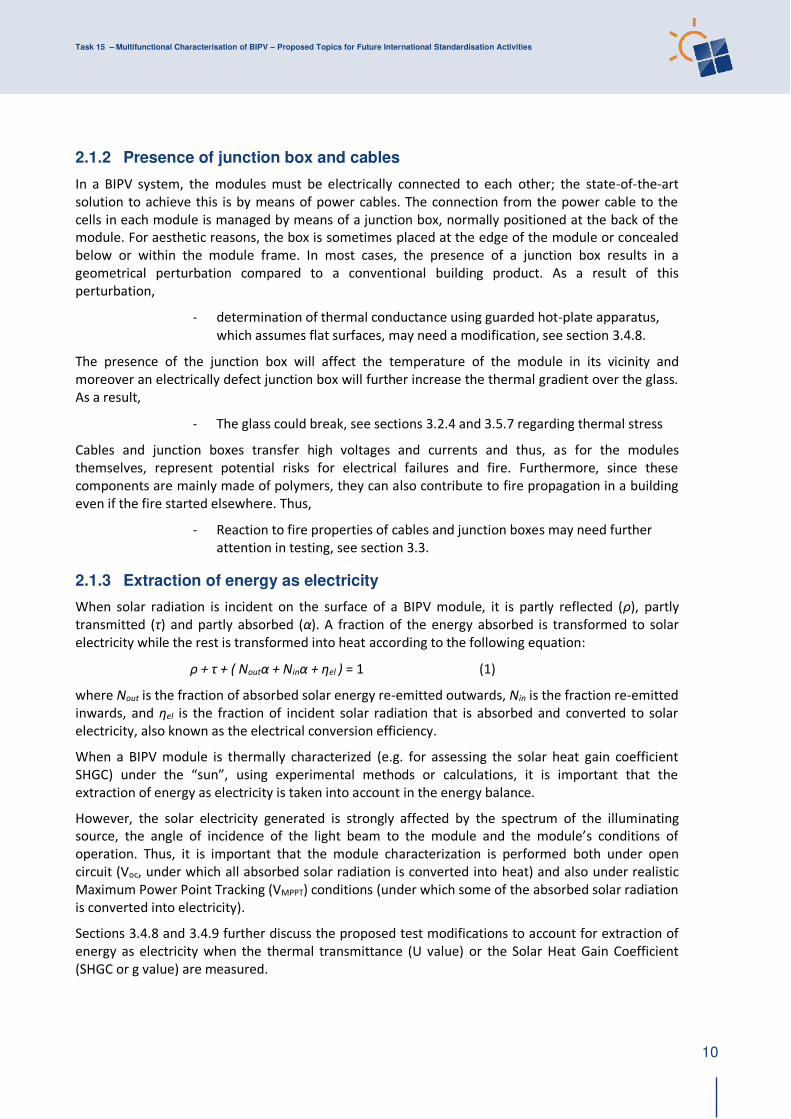
2.1.2 Presence of junction box and cables
In a BIPV system, the modules must be electrically connected to each other; the state-of-the-art
solution to achieve this is by means of power cables. The connection from the power cable to the
cells in each module is managed by means of a junction box, normally positioned at the back of the
module. For aesthetic reasons, the box is sometimes placed at the edge of the module or concealed
below or within the module frame. In most cases, the presence of a junction box results in a
geometrical perturbation compared to a conventional building product. As a result of this
perturbation,
- determination of thermal conductance using guarded hot-plate apparatus,
which assumes flat surfaces, may need a modification, see section 3.4.8.
The presence of the junction box will affect the temperature of the module in its vicinity and
moreover an electrically defect junction box will further increase the thermal gradient over the glass.
As a result,
- The glass could break, see sections 3.2.4 and 3.5.7 regarding thermal stress
Cables and junction boxes transfer high voltages and currents and thus, as for the modules
themselves, represent potential risks for electrical failures and fire. Furthermore, since these
components are mainly made of polymers, they can also contribute to fire propagation in a building
even if the fire started elsewhere. Thus,
- Reaction to fire properties of cables and junction boxes may need further
attention in testing, see section 3.3.
2.1.3 Extraction of energy as electricity
When solar radiation is incident on the surface of a BIPV module, it is partly reflected (ρ), partly
transmitted (τ) and partly absorbed (α). A fraction of the energy absorbed is transformed to solar
electricity while the rest is transformed into heat according to the following equation:
ρ + τ + ( Noutα + Ninα + ηel ) = 1 (1)
where Nout is the fraction of absorbed solar energy re-emitted outwards, Nin is the fraction re-emitted
inwards, and ηel is the fraction of incident solar radiation that is absorbed and converted to solar
electricity, also known as the electrical conversion efficiency.
When a BIPV module is thermally characterized (e.g. for assessing the solar heat gain coefficient
SHGC) under the “sun”, using experimental methods or calculations, it is important that the extraction of energy as electricity is taken into account in the energy balance.
However, the solar electricity generated is strongly affected by the spectrum of the illuminating
source, the angle of incidence of the light beam to the module and the module’s conditions of operation. Thus, it is important that the module characterization is performed both under open
circuit (Voc, under which all absorbed solar radiation is converted into heat) and also under realistic
Maximum Power Point Tracking (VMPPT) conditions (under which some of the absorbed solar radiation
is converted into electricity).
Sections 3.4.8 and 3.4.9 further discuss the proposed test modifications to account for extraction of
energy as electricity when the thermal transmittance (U value) or the Solar Heat Gain Coefficient
(SHGC or g value) are measured.
Task 15 – Multifunctional Characterisation of BIPV – Proposed Topics for Future International Standardisation Activities
11
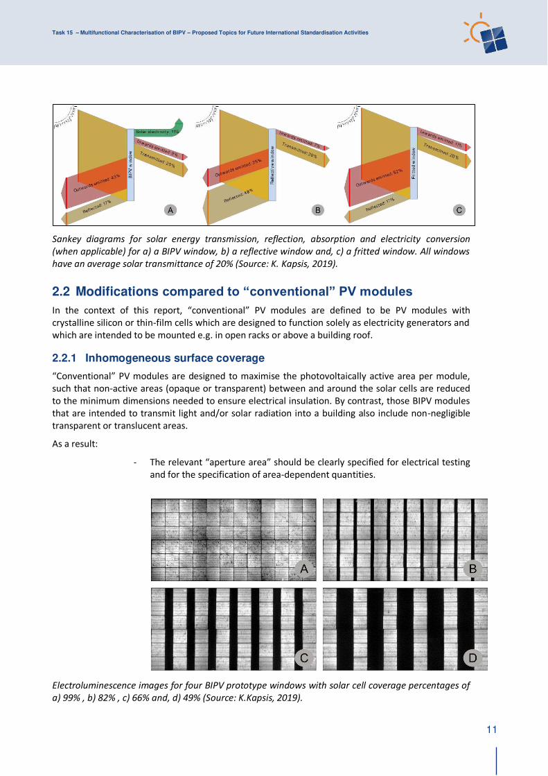
Sankey diagrams for solar energy transmission, reflection, absorption and electricity conversion
(when applicable) for a) a BIPV window, b) a reflective window and, c) a fritted window. All windows
have an average solar transmittance of 20% (Source: K. Kapsis, 2019).
2.2 Modifications compared to “conventional” PV modules
In the context of this report, “conventional” PV modules are defined to be PV modules with
crystalline silicon or thin-film cells which are designed to function solely as electricity generators and
which are intended to be mounted e.g. in open racks or above a building roof.
2.2.1 Inhomogeneous surface coverage
“Conventional” PV modules are designed to maximise the photovoltaically active area per module, such that non-active areas (opaque or transparent) between and around the solar cells are reduced
to the minimum dimensions needed to ensure electrical insulation. By contrast, those BIPV modules
that are intended to transmit light and/or solar radiation into a building also include non-negligible
transparent or translucent areas.
As a result:
- The relevant “aperture area” should be clearly specified for electrical testing and for the specification of area-dependent quantities.
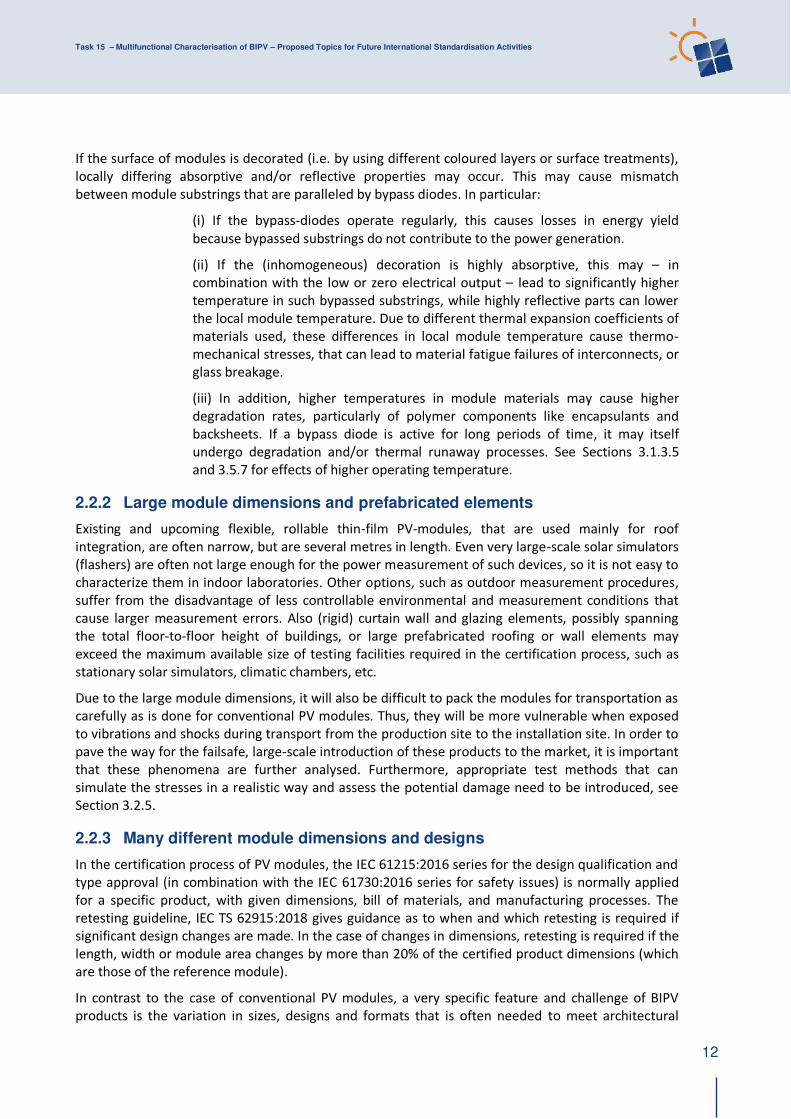
Electroluminescence images for four BIPV prototype windows with solar cell coverage percentages of
a) 99% , b) 82% , c) 66% and, d) 49% (Source: K.Kapsis, 2019).
Task 15 – Multifunctional Characterisation of BIPV – Proposed Topics for Future International Standardisation Activities
12
If the surface of modules is decorated (i.e. by using different coloured layers or surface treatments),
locally differing absorptive and/or reflective properties may occur. This may cause mismatch
between module substrings that are paralleled by bypass diodes. In particular:
(i) If the bypass-diodes operate regularly, this causes losses in energy yield
because bypassed substrings do not contribute to the power generation.
(ii) If the (inhomogeneous) decoration is highly absorptive, this may – in
combination with the low or zero electrical output – lead to significantly higher
temperature in such bypassed substrings, while highly reflective parts can lower
the local module temperature. Due to different thermal expansion coefficients of
materials used, these differences in local module temperature cause thermo-
mechanical stresses, that can lead to material fatigue failures of interconnects, or
glass breakage.
(iii) In addition, higher temperatures in module materials may cause higher
degradation rates, particularly of polymer components like encapsulants and
backsheets. If a bypass diode is active for long periods of time, it may itself
undergo degradation and/or thermal runaway processes. See Sections 3.1.3.5
and 3.5.7 for effects of higher operating temperature.
2.2.2 Large module dimensions and prefabricated elements
Existing and upcoming flexible, rollable thin-film PV-modules, that are used mainly for roof
integration, are often narrow, but are several metres in length. Even very large-scale solar simulators
(flashers) are often not large enough for the power measurement of such devices, so it is not easy to
characterize them in indoor laboratories. Other options, such as outdoor measurement procedures,
suffer from the disadvantage of less controllable environmental and measurement conditions that
cause larger measurement errors. Also (rigid) curtain wall and glazing elements, possibly spanning
the total floor-to-floor height of buildings, or large prefabricated roofing or wall elements may
exceed the maximum available size of testing facilities required in the certification process, such as
stationary solar simulators, climatic chambers, etc.
Due to the large module dimensions, it will also be difficult to pack the modules for transportation as
carefully as is done for conventional PV modules. Thus, they will be more vulnerable when exposed
to vibrations and shocks during transport from the production site to the installation site. In order to
pave the way for the failsafe, large-scale introduction of these products to the market, it is important
that these phenomena are further analysed. Furthermore, appropriate test methods that can
simulate the stresses in a realistic way and assess the potential damage need to be introduced, see
Section 3.2.5.
2.2.3 Many different module dimensions and designs
In the certification process of PV modules, the IEC 61215:2016 series for the design qualification and
type approval (in combination with the IEC 61730:2016 series for safety issues) is normally applied
for a specific product, with given dimensions, bill of materials, and manufacturing processes. The
retesting guideline, IEC TS 62915:2018 gives guidance as to when and which retesting is required if
significant design changes are made. In the case of changes in dimensions, retesting is required if the
length, width or module area changes by more than 20% of the certified product dimensions (which
are those of the reference module).
In contrast to the case of conventional PV modules, a very specific feature and challenge of BIPV
products is the variation in sizes, designs and formats that is often needed to meet architectural
Task 15 – Multifunctional Characterisation of BIPV – Proposed Topics for Future International Standardisation Activities
13
design requirements and to match building dimensions. So-called ‘custom-sized PV modules’ are mostly glass-glass modules based on crystalline silicon or thin-film PV technology. More recently,
modules based on thin films deposited onto metal foil or organic, perovskite or dye solar cells have
entered the market. Typically the producers of custom-sized BIPV modules have a general ‘recipe’ to produce the solar modules. This means that the type of glass, the interlayers, the interconnectors,
the junction boxes and the cells are always the same, but the dimensions and power output might
vary. In the case of glass-glass modules, the glass thickness is individually calculated according to the
area of the module, function of the module, local building requirements, location in the building
(height, wind load), fixings and use of the solar module.
Most custom-sized module producers also work, due to design considerations, with more than one
cell type. Totally black cells, back-contact cells, bifacial cells, coloured solar cells, semitransparent
cells and others are on offer.
Furthermore, variations in cover glass treatment, such as sandblasting or screen-printing, are
demanded by the market.
If the rigid rules applying to the definition and electrical testing of conventional modules are applied,
this represents a major obstacle to bringing tested and approved custom-sized and/or individually
designed BIPV modules to the market in a safe, economic and reliable manner. More flexibility and
options for design variations need to be taken into account for viable BIPV module standardization,
testing and certification. This affects the testing of electrical, mechanical and optical properties.
2.2.4 Many different substructures and mounting methods of BIPV modules
The testing for conventional PV modules includes mechanical testing of the modules with the specific
fixings attached under conditions applying for the specified locations. Both are specified by the
producer. Corresponding processes occur with custom-sized BIPV modules manufactured e.g. as
glass-glass modules. A BIPV module of given dimensions has a different mechanical resistance
depending on the attachment fittings. Regarding glass panes and laminates, different types and
thicknesses of glass and interlayers may be required, depending on whether the attachment fitting
extend along all four sides or are at only individual points.
Again, more flexibility and options for design variations need to be foreseen to achieve practicable
BIPV module standardization, testing and certification.
2.2.5 Curved modules
Different elements with different tilt directions within a “single BIPV element” can affect power production when differently oriented cells are connected in series. On a curved surface, each cell
receives a different irradiation level at the same time, which leads to energy mismatch and therefore
can lead to hot-spot generation and power decrease. This affects:
- the dimensioning of electrical and safety elements if the module uses an
unconventional number of cells, requiring modification of e.g. diode
characteristics, ribbons or string size.
- stress constraints with wind, water and snow loads (and combinations
thereof), stress constraints with suction (reverse load) and thermal stress
(due not only to a difference between front and back surface temperatures
but also to the modification of radiation absorption according to the
orientation with respect to incident solar radiation).
Task 15 – Multifunctional Characterisation of BIPV – Proposed Topics for Future International Standardisation Activities
14
2.2.6 Presence of junction box and cables
The fact that the junction box in a BIPV system in general will be concealed in a space between the
module and the underlying surface makes it more difficult to access compared to a BAPV installation.
This will impede inspection, e.g. by means of an IR camera, and thus increase the risk of electric
failures not being detected.
2.3 Effect of installation in the built environment
A very general distinction can be made between conventional PV modules and BIPV elements:
Conventional modules:
- Conventional solar modules as “electric products” are defined by an almost
globally accepted general set of IEC standards and UL standards
- Conventional modules are therefore standardized as “objects” in their own right in an internationally “homogeneous” manner
BIPV modules installed in the built environment:
- BIPV modules are not only subject to the set of PV standards mentioned in
Section 2.2.3 but their installation in the built environment also means that
construction standards, rules and requirements apply.
- Requirements on BIPV modules are imposed – often in a legally binding
manner - by the environment / location / installation and use.
This means that BIPV modules are not only the subject of “object”-defined standards, but also of
“context”-defined standards:
- Geographical location and height of the building / BIPV application changes
the required characteristic of the BIPV element regarding its ability to deal
with the resulting natural forces like snow loads, wind loads, heat, hail, fire
safety requirements
- The location in the building and building type can change the requirements
regarding e.g. the required fire safety classes and certificates as well as the
required structural strength and testing
- National / regional construction codes (laws) and standards might set out
different requirements
2.3.1 Frequent (partial) shading
Partial shading occurs when one or more PV cells in a PV module receive less irradiance than the rest,
due to the existence of nearby or distant objects that prevent radiation from reaching the complete
PV module surface. Due to architectural and urban constraints, partial shading occurs more
frequently in PV modules integrated in buildings than in ground-mounted power plants.
Partial shading can lead not only to significant reduction of the energy yield of the PV system but also
to appreciable temperature increase (hot spots) of shaded PV cells if they are forced to work as loads
for the other PV cells. This can even cause irreversible damage to the materials. Both electrical and
thermal effects will depend on the geometry and distance of the shading object and on the design of
the PV module. The BIPV module location in the building envelope and its electrical configuration
(number, distribution and connection of PV cells and bypass diodes) are decisive.

Task 15 – Multifunctional Characterisation of BIPV – Proposed Topics for Future International Standardisation Activities
15
The most critical situations occur if the differences in irradiance on different parts of the modules are
large. Especially harmful is partial shading under high irradiance conditions, for instance around noon
under clear sky conditions and with shading from a close object.
Shading from close objects, i.e. objects causing an umbra shadow on the module’s active cell area may cause
(i) excessive heat in shaded parts (hot spots), accelerating degradation
processes, and/or
(ii) sudden, permanent power degradation in some thin-film technologies
with monolithic, series-connected cell structures, if a linear shadow covers
one or a few series-connected cells over almost the whole cell width.
In general, shading from distant objects during the first or last hours of the day does not impact
significantly on the PV modules’ durability, although it reduces the PV energy yield.
Photo of a building equipped with a complex BIPV system and its RADIANCE model, illustrating cases
of partial shading [2].
2.3.2 Radiation frequently incident at non-normal incidence
The reflectance of a flat-surface PV module under real operating conditions, with light coming from
different angles, is generally greater than the reflectance at normal incidence at which the electrical
characteristics of a PV module are commonly supplied.
The reflectance increase with the angle of incidence (AOI) means a decrease of the PV electricity
generation. Reflection losses on an annual basis can become especially significant in those BIPV
applications in which PV modules are positioned far from the optimum orientation regarding the
maximum annual yield [3].
The determination of such annual angular losses for each surface should be considered for the case
of BIPV, as a tool to help in the decision-making when designing a building with BIPV.
2.3.3 Indirect irradiation
The proximity of different objects and building surfaces can cause indirect irradiation of the BIPV
modules, increasing their electricity yield [4]. To be aware of the local irradiation of the PV modules,
it would be necessary to monitor the plane-of-array irradiance.
This is particularly relevant for bifacial modules, where the plane-of-array irradiance for both
surfaces should be known. Bifacial PV modules can significantly increase their performance when
installed in applications such as awnings over surfaces having high albedo coefficients, such as white
painted walls (albedo coefficients up to 0.9).

Task 15 – Multifunctional Characterisation of BIPV – Proposed Topics for Future International Standardisation Activities
16
Indirect radiation will be incident on different cells or sections of curved elements at different angles
of incidence. This can create inhomogeneous power generation from the different cells. The correct
impact of partial or non-uniform reflection has to be evaluated under corresponding conditions.
Bifacial BIPV window testing at Concordia University's Solar Simulator and Environmental Chamber
laboratory, under background solar reflectance of A) 66% and B) 6% (Source: K.Kapsis, 2019).
2.3.4 Application as a daylighting element
Semi-transparent PV modules integrated into building envelopes allow electricity generation to be
combined with solar control and daylighting properties. The procedures included in the current
standards for determining the luminous characteristics of glazing in buildings, such as ISO 9050 and
EN 410, can also be applied to semi-transparent PV modules for building integration. The parameters
obtained, such as light transmittance, combined with the colour rendering index describe the
daylighting properties of the semi-transparent BIPV modules.
Sections 3.4.1 to 3.4.5 discuss test modifications with regard to optical and colour rendering
properties.
2.3.5 Potential source of indoor glare
BIPV modules, consisting of photovoltaic cells surrounded by areas of transparent encapsulant, result
in alternation between transmitted light and shadows cast by the opaque PV cells. By altering the
spacing between opaque PV cells, simple (e.g., equally spaced cells) to complex patterns (e.g. PV cells
acting as pixels of an image drawn on the building façade) can be generated by the distribution of
darker and brighter areas on the building façade. However, this alternation between bright and dark
spots within the visual field of the occupants creates the potential for discomfort glare to occur.
Section 3.4.6 discusses the assessment of discomfort glare due to daylight in buildings with a non-
uniform source luminance such as a BIPV window and the associated challenges with such a
procedure.
Task 15 – Multifunctional Characterisation of BIPV – Proposed Topics for Future International Standardisation Activities
17
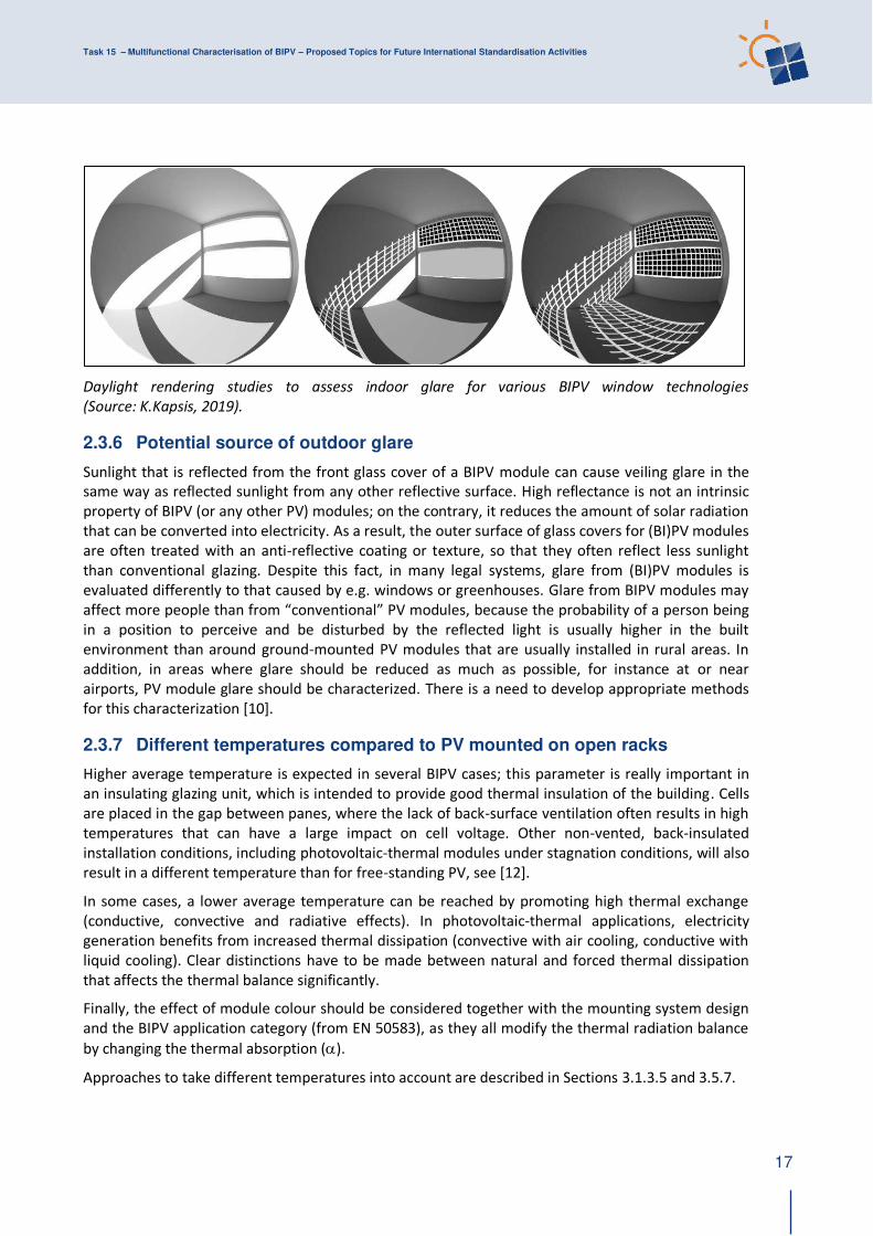
Daylight rendering studies to assess indoor glare for various BIPV window technologies
(Source: K.Kapsis, 2019).
2.3.6 Potential source of outdoor glare
Sunlight that is reflected from the front glass cover of a BIPV module can cause veiling glare in the
same way as reflected sunlight from any other reflective surface. High reflectance is not an intrinsic
property of BIPV (or any other PV) modules; on the contrary, it reduces the amount of solar radiation
that can be converted into electricity. As a result, the outer surface of glass covers for (BI)PV modules
are often treated with an anti-reflective coating or texture, so that they often reflect less sunlight
than conventional glazing. Despite this fact, in many legal systems, glare from (BI)PV modules is
evaluated differently to that caused by e.g. windows or greenhouses. Glare from BIPV modules may
affect more people than from “conventional” PV modules, because the probability of a person being in a position to perceive and be disturbed by the reflected light is usually higher in the built
environment than around ground-mounted PV modules that are usually installed in rural areas. In
addition, in areas where glare should be reduced as much as possible, for instance at or near
airports, PV module glare should be characterized. There is a need to develop appropriate methods
for this characterization [10].
2.3.7 Different temperatures compared to PV mounted on open racks
Higher average temperature is expected in several BIPV cases; this parameter is really important in
an insulating glazing unit, which is intended to provide good thermal insulation of the building. Cells
are placed in the gap between panes, where the lack of back-surface ventilation often results in high
temperatures that can have a large impact on cell voltage. Other non-vented, back-insulated
installation conditions, including photovoltaic-thermal modules under stagnation conditions, will also
result in a different temperature than for free-standing PV, see [12].
In some cases, a lower average temperature can be reached by promoting high thermal exchange
(conductive, convective and radiative effects). In photovoltaic-thermal applications, electricity
generation benefits from increased thermal dissipation (convective with air cooling, conductive with
liquid cooling). Clear distinctions have to be made between natural and forced thermal dissipation
that affects the thermal balance significantly.
Finally, the effect of module colour should be considered together with the mounting system design
and the BIPV application category (from EN 50583), as they all modify the thermal radiation balance
by changing the thermal absorption ().
Approaches to take different temperatures into account are described in Sections 3.1.3.5 and 3.5.7.
Task 15 – Multifunctional Characterisation of BIPV – Proposed Topics for Future International Standardisation Activities
18
2.3.8 Building-specific fire safety requirements
BIPV modules have to meet the requirements set out by local and national construction rules. In
some countries, e.g. Germany, the so-called “hard roofing test” is demanded for roofs. These fire
tests vary even within European countries.
However, when the building with a BIPV roof is far enough away from other buildings, this test may
not be necessary (context-driven requirement).
Regarding façade installations, the required fire resistance class depends on:
- Building type and usage
- Building height
- Construction of the wall as a whole element (wood, concrete etc. might result
in different requirements for the fire resistance class of the cladding)
- Application of ‘sprinklers’ in the building
Given these factors, the required fire resistance class of the BIPV element can range between ‘no requirements’ and the legally binding requirement of ‘non-combustible’, which most BIPV products cannot fulfil due to the lamination material incorporated.
Fundamental requirements related to fire safety are not internationally harmonized and if national
regulations are not established, the range of tests in IEC 61730-2 for conventional PV modules can be
applied as an initial set of minimum tests for BIPV. Annex B of IEC 61730-2, namely “Fire-test, spread-
of-flame and burning tests for PV modules”, refers to the well-established tests e.g. ENV 1187:2002,
Parts 1 to 4 (now superseded by CEN/TS 1187:2012), and UL 1703:2015 (used in USA for the past
decades). The UL 1703 in turn, refers to UL 790 in the case of building-integrated PV.
Further improvements need to be achieved by combining the requirements of BIPV as an electrical
device (under IEC standards) and building material (under ISO, BS, EN standards). Combined fire
safety tests need to comply with the building codes existing in each country. Additional preventive
measures may be included, such as fire-break requirements (laterally and vertically), active fire-
fighting systems and extinguishment solutions. It can be well justified to impose more strict
requirements for automatic fault detection- and handling in systems where connectors and junction
boxes cannot be easily accessed for routine inspection and maintenance.
In order to speed up the urgently needed practical implementation of new standards and
requirements, the development of practical guidelines should go hand in hand with the former.
2.3.9 Building-application-specific mechanical requirements
BIPV modules must be characterised by the property of “post-breakage integrity”. This is the
property that a broken BIPV element must remain safe (e.g. not fall apart or slip out of its frame)
under a load for a predefined period of time. This is to ensure both that persons cannot be injured by
a broken BIPV element falling down onto them and that a BIPV module that is used for a barrier
function, e.g. as a balcony balustrade, continues to prevent a person from falling through it for a
predefined period of time even after breakage.
Requirements relating to mechanical resistance and stability vary extensively depending on the
application, whether as a roofing or façade element or a solar shading device, and also on the
building typology (e.g. private or public). Compared to ground-mounted PV modules, some aspects of
the built environment affecting mechanical requirements include higher mounting positions and thus
greater wind loads, and the greater safety margin needed when building occupants are nearby, e.g.
underneath glass-glass modules applied as overhead glazing.
Task 15 – Multifunctional Characterisation of BIPV – Proposed Topics for Future International Standardisation Activities
19
2.3.10 Long expected lifetime as a building product
The expectation of durability for BIPV modules may be greater than for conventional modules,
because replacement of a failed BIPV module is often mechanically more difficult than is the case for
conventional free-standing PV modules. Therefore longer usage times of BIPV than for conventional
modules should be taken into account for the test methods and the benchmark criteria for both
functions, as an electricity generator and as a building component.
Task 15 – Multifunctional Characterisation of BIPV – Proposed Topics for Future International Standardisation Activities
20
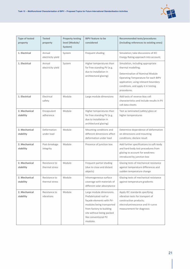
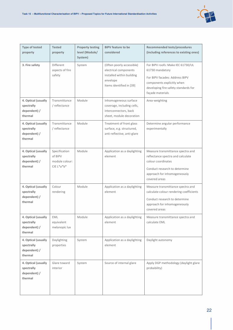
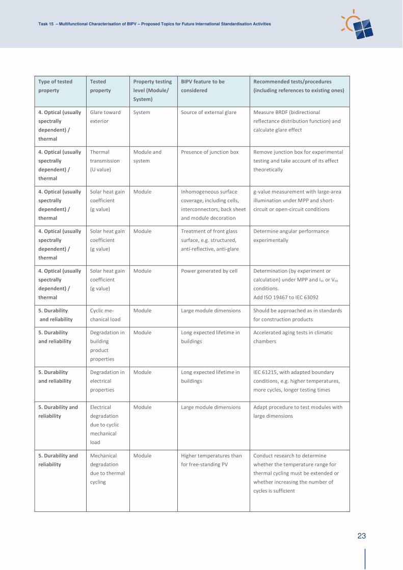
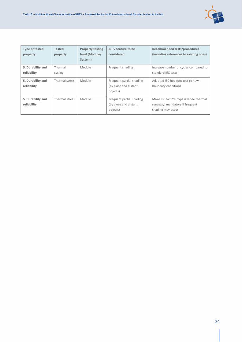
3 TYPES OF TESTING AND PROPOSED TEST MODIFICATIONS TO ACCOUNT FOR BIPV FEATURES
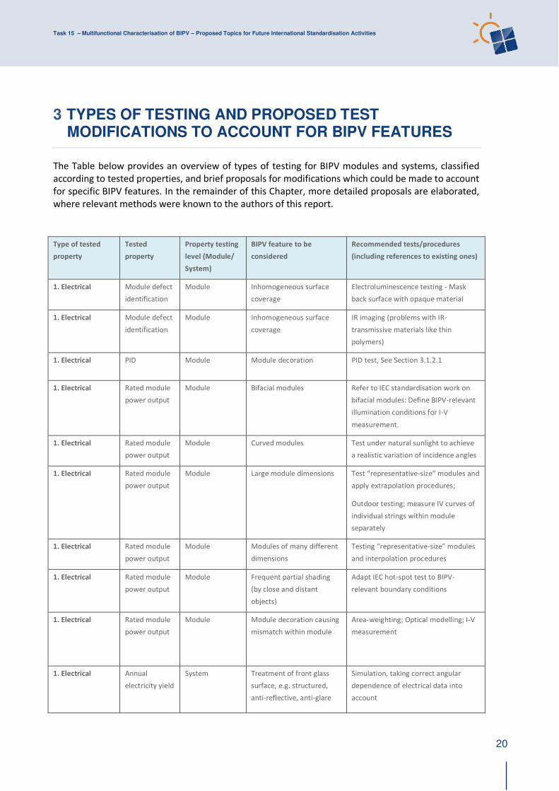
The Table below provides an overview of types of testing for BIPV modules and systems, classified
according to tested properties, and brief proposals for modifications which could be made to account
for specific BIPV features. In the remainder of this Chapter, more detailed proposals are elaborated,
where relevant methods were known to the authors of this report.
Type of tested
property
Tested
property
Property testing
level (Module/
System)
BIPV feature to be
considered
Recommended tests/procedures
(including references to existing ones)
1. Electrical Module defect
identification
Module Inhomogeneous surface
coverage
Electroluminescence testing - Mask
back surface with opaque material
1. Electrical Module defect
identification
Module Inhomogeneous surface
coverage
IR imaging (problems with IR-
transmissive materials like thin
polymers)
1. Electrical PID Module Module decoration PID test, See Section 3.1.2.1
1. Electrical Rated module
power output
Module Bifacial modules Refer to IEC standardisation work on
bifacial modules: Define BIPV-relevant
illumination conditions for I-V
measurement.
1. Electrical Rated module
power output
Module Curved modules Test under natural sunlight to achieve
a realistic variation of incidence angles
1. Electrical Rated module
power output
Module Large module dimensions Test “representative-size” modules and apply extrapolation procedures;
Outdoor testing; measure IV curves of
individual strings within module
separately
1. Electrical Rated module
power output
Module Modules of many different
dimensions
Testing “representative-size” modules and interpolation procedures
1. Electrical Rated module
power output
Module Frequent partial shading
(by close and distant
objects)
Adapt IEC hot-spot test to BIPV-
relevant boundary conditions
1. Electrical Rated module
power output
Module Module decoration causing
mismatch within module
Area-weighting; Optical modelling; I-V
measurement
1. Electrical Annual
electricity yield
System Treatment of front glass
surface, e.g. structured,
anti-reflective, anti-glare
Simulation, taking correct angular
dependence of electrical data into
account
Task 15 – Multifunctional Characterisation of BIPV – Proposed Topics for Future International Standardisation Activities
21
Type of tested
property
Tested
property
Property testing
level (Module/
System)
BIPV feature to be
considered
Recommended tests/procedures
(including references to existing ones)
1. Electrical Annual
electricity yield
System Frequent shading Simulation; take discussions of IEC
Energy Rating approach into account;
1. Electrical Annual
electricity yield
System Higher temperatures than
for free-standing PV (e.g.
due to installation in
architectural glazing)
Simulation, including appropriate
thermal modelling;
Determination of Nominal Module
Operating Temperature for each BIPV
application, using relevant boundary
conditions, and apply it in testing
procedures.
1. Electrical Electrical
safety
Module Large module dimensions Add tests of reverse-bias cell
characteristics and include results in PV
cell data sheets
2. Mechanical
stability
Encapsulant
adherence
Module Higher temperatures than
for free-standing PV (e.g.
due to installation in
architectural glazing)
Test as laminated (safety) glass at
higher temperatures
2. Mechanical
stability
Deformation
under load
Module Mounting conditions and
different dimensions affect
deformation under load
Determine dependence of deformation
on dimensions and mounting
conditions; declare result
2. Mechanical
stability
Post-breakage
integrity
Module Presence of junction box Add further specifications to soft-body
and hard-body test procedures from
glazing to account for weakness
introduced by junction box
2. Mechanical
stability
Resistance to
thermal stress
Module Frequent partial shading
(due to close and distant
objects)
Glazing tests of mechanical resistance
against temperature differences and
sudden temperature change
2. Mechanical
stability
Resistance to
thermal stress
Module Inhomogeneous surface
coverage with materials of
different solar absorptance
Glazing tests of mechanical resistance
against temperature gradients
2. Mechanical
stability
Resistance to
vibrations
Module Large module dimensions.
Prefabricated roof or
façade elements with PV-
modules being transported
from factory to building
site without being packed
like conventional PV
modules
Apply IEC standards specifying
vibration tests for transport of
construction products;
electroluminescence and IV-curve
measurement for diagnosis
Task 15 – Multifunctional Characterisation of BIPV – Proposed Topics for Future International Standardisation Activities
22
Type of tested
property
Tested
property
Property testing
level (Module/
System)
BIPV feature to be
considered
Recommended tests/procedures
(including references to existing ones)
3. Fire safety Different
aspects of fire
safety
System (Often poorly accessible)
electrical components
installed within building
envelope
Items identified in [39]
For BIPV roofs: Make IEC 61730/UL
61730 mandatory
For BIPV facades: Address BIPV
components explicitly when
developing fire safety standards for
façade materials
4. Optical (usually
spectrally
dependent) /
thermal
Transmittance
/ reflectance
Module Inhomogeneous surface
coverage, including cells,
interconnectors, back
sheet, module decoration
Area-weighting
4. Optical (usually
spectrally
dependent) /
thermal
Transmittance
/ reflectance
Module Treatment of front glass
surface, e.g. structured,
anti-reflective, anti-glare
Determine angular performance
experimentally
4. Optical (usually
spectrally
dependent) /
thermal
Specification
of BIPV
module colour:
CIE L*a*b*
Module Application as a daylighting
element
Measure transmittance spectra and
reflectance spectra and calculate
colour coordinates
Conduct research to determine
approach for inhomogeneously
covered areas
4. Optical (usually
spectrally
dependent) /
thermal
Colour
rendering
Module Application as a daylighting
element
Measure transmittance spectra and
calculate colour rendering coefficients
Conduct research to determine
approach for inhomogeneously
covered areas
4. Optical (usually
spectrally
dependent) /
thermal
EML
equivalent
melanopic lux
Module Application as a daylighting
element
Measure transmittance spectra and
calculate EML
4. Optical (usually
spectrally
dependent) /
thermal
Daylighting
properties
System Application as a daylighting
element
Daylight autonomy
4. Optical (usually
spectrally
dependent) /
thermal
Glare toward
interior
System Source of internal glare Apply DGP methodology (daylight glare
probability)
Task 15 – Multifunctional Characterisation of BIPV – Proposed Topics for Future International Standardisation Activities
23
Type of tested
property
Tested
property
Property testing
level (Module/
System)
BIPV feature to be
considered
Recommended tests/procedures
(including references to existing ones)
4. Optical (usually
spectrally
dependent) /
thermal
Glare toward
exterior
System Source of external glare Measure BRDF (bidirectional
reflectance distribution function) and
calculate glare effect
4. Optical (usually
spectrally
dependent) /
thermal
Thermal
transmission
(U value)
Module and
system
Presence of junction box Remove junction box for experimental
testing and take account of its effect
theoretically
4. Optical (usually
spectrally
dependent) /
thermal
Solar heat gain
coefficient
(g value)
Module Inhomogeneous surface
coverage, including cells,
interconnectors, back sheet
and module decoration
g-value measurement with large-area
illumination under MPP and short-
circuit or open-circuit conditions
4. Optical (usually
spectrally
dependent) /
thermal
Solar heat gain
coefficient
(g value)
Module Treatment of front glass
surface, e.g. structured,
anti-reflective, anti-glare
Determine angular performance
experimentally
4. Optical (usually
spectrally
dependent) /
thermal
Solar heat gain
coefficient
(g value)
Module Power generated by cell Determination (by experiment or
calculation) under MPP and Isc or Voc
conditions.
Add ISO 19467 to IEC 63092
5. Durability
and reliability
Cyclic me-
chanical load
Module Large module dimensions Should be approached as in standards
for construction products
5. Durability
and reliability
Degradation in
building
product
properties
Module Long expected lifetime in
buildings
Accelerated aging tests in climatic
chambers
5. Durability
and reliability
Degradation in
electrical
properties
Module Long expected lifetime in
buildings
IEC 61215, with adapted boundary
conditions, e.g. higher temperatures,
more cycles, longer testing times
5. Durability and
reliability
Electrical
degradation
due to cyclic
mechanical
load
Module Large module dimensions Adapt procedure to test modules with
large dimensions
5. Durability and
reliability
Mechanical
degradation
due to thermal
cycling
Module Higher temperatures than
for free-standing PV
Conduct research to determine
whether the temperature range for
thermal cycling must be extended or
whether increasing the number of
cycles is sufficient
Task 15 – Multifunctional Characterisation of BIPV – Proposed Topics for Future International Standardisation Activities
24
Type of tested
property
Tested
property
Property testing
level (Module/
System)
BIPV feature to be
considered
Recommended tests/procedures
(including references to existing ones)
5. Durability and
reliability
Thermal
cycling
Module Frequent shading Increase number of cycles compared to
standard IEC tests
5. Durability and
reliability
Thermal stress Module Frequent partial shading
(by close and distant
objects)
Adapted IEC hot-spot test to new
boundary conditions
5. Durability and
reliability
Thermal stress Module Frequent partial shading
(by close and distant
objects)
Make IEC 62979 (bypass diode thermal
runaway) mandatory if frequent
shading may occur
Task 15 – Multifunctional Characterisation of BIPV – Proposed Topics for Future International Standardisation Activities
25
3.1 Electrical
3.1.1 Module defect identification
See Table above
3.1.2 Potential-induced Degradation (PID)
PID is a failure mode that occurs both in glass-backsheet PV module packages with EVA
encapsulation systems and glass-glass designs. In fact, PID has also been observed in the
encapsulation systems for other crystalline cells and thin films as well [19], [20].
Degradation effects in PV systems due to ion migration caused by leakage currents in modules have
been known for a long time [14], both in crystalline and thin-film based modules. Whether a string of
PV modules suffers from Potential-Induced Degradation (PID) effects in an application or not strongly
depends on the bill of materials, the electrical system configuration and micro-climatic effects.
Within the IEA PVPS Task 13 “Performance and Reliability of PV Systems” the review reports IEA-
PVPS T13-01:2014 [15] and IEA-PVPS T13-09:2017 [16] include a brief overview of these degradation
effects. For a detailed review see [18].
3.1.2.1 Surface decoration
Coloured intermediate layers in front of the cells, and glass coatings used in BIPV, may significantly
change the electrical resistivity of the insulation system, and therefore PID susceptibility.
Potential-induced degradation effects, such as reduced parallel resistance, polarization effects, cell
degradation, delamination, TCO corrosion and “bar-graphing” may lead to severe power loss,
aesthetic issues, and electrical and mechanical safety problems. Up to now, PID tests are not
mandatory in PV certification. In addition the test conditions of existing tests focus on “conventional” module design and field applications. If frequent condensation occurs, or more generally, if modules
are used in a very wet environment, the ‘foil test’, described as one of two optional PID tests in IEC TS 62804-1:2015 (Ed. 1), may reflect the usage conditions better than the ‘chamber test’ that will be referenced in the future IEC 61215-2 Ed.2. Therefore, both test variants should be kept for BIPV
products.
3.1.3 Rated module power output
See Table above and elaboration below
The rated PV module power output under Standard Test Conditions (STC) is obtained under a
combination of temperature and solar irradiance conditions that was defined in IEC standards for the
purpose of testing PV devices under reproducible and practicable conditions.. These conditions are
seldom experienced either in conventional PV systems or in BIPV systems, so there is no need to
modify STC for BIPV modules.
However, a realistic evaluation of BIPV module output power should consider all the BIPV electrical
features described in the Table above. Assessment of photovoltaic conversion could be validated by
using IEC 60904-1:2006, which specifies procedures for measurement of photovoltaic current-voltage
characteristics.
The nature of thermal exchange can drastically affect the thermal balance of BIPV components, so
specific values of NOCT (nominal operating cell temperature, measured under open circuit) are to be
evaluated according to each building-integration mode in order to modify thermal models and their
effect on electricity generation. NMOT (nominal module operating temperature, measured at MPP)
or an equivalent model should be adapted for its application to BIPV. It is recommended to add a
Task 15 – Multifunctional Characterisation of BIPV – Proposed Topics for Future International Standardisation Activities
26
note to the relevant standards explicitly mentioning the need to choose relevant testing conditions
for BIPV systems.
In IEC 60891, procedures for temperature and irradiance corrections to measured
I-V characteristics of crystalline silicon photovoltaic devices are specified. When the relevant
temperatures experienced by BIPV modules are to be determined for these corrections, account
must be taken of the generally higher levels of thermal insulation compared to conventional PV.
When applying IEC 60904-5 to determine the equivalent cell temperature (ECT) of photovoltaic (PV)
devices by the open-circuit voltage method, again it must be ensured that the thermal conditions
during testing are applicable for BIPV modules.
The calculation of the angle of incidence modifier AOI is addressed in the IEC 61853-2, currently
under revision, and is applicable to BIPV modules. There is no need to modify the current standard.
The second edition of IEC 61215-2, currently in preparation, adds test conditions considering bifacial
PV modules and applications based on the nameplate values stated by the manufacturer according
to IEC 61215-1. The recent IEC TS 60904-1-2:2019 describes the procedures to determine I-V curves
and power generation by means and measurement of bifaciality coefficients of a PV module. Care
must be taken to use an appropriate maximum irradiance value for the back surface, taking
underlying surfaces with high albedo into account, when the necessary additional nameplate
irradiance value is determined.
3.1.3.1 Large module dimensions
If modules are too large to test them as a whole in a solar simulator,
(i) the measurement of the I-V characteristics may be split up into several
sequential measurements in some cases, if inner electric connections (e.g. at
the points of bypass diodes) are accessible, or
(ii) a measurement of the I-V of a “representative sample”1 with smaller
dimensions may be executed, or
(iii) such a large module may be measured outdoors.
In all cases, appropriate measures are needed to transform I-V characteristics, which may be
determined either from indoor measurements of parts or representative samples or from a series of
outdoor measurements, to a single I-V characteristic of the whole (large) module.
The calculation of the combined current-voltage characteristic and total power of series and/or
parallel connected sub-section is simple, if all parts have identical characteristics, but can be rather
complicated if different current-voltage characteristics have to be considered. This is often the case
for curved elements (see Section 2.2.5), and if inhomogeneous surface decoration is applied (see
Section 2.1.1.1).
1 The planned new edition of the IEC 61215 series (new Ed.2) and Amendments to the IEC 61730 Ed.2 series
(new AMD1 Ed.2), will introduce the term “representative sample”, defined as “a sample that includes all the components of the module, except some repeated parts. The representative samples shall use all key materials
and subassemblies.”
Task 15 – Multifunctional Characterisation of BIPV – Proposed Topics for Future International Standardisation Activities
27
Therefore it is necessary to develop tests and procedures to derive I-V characteristics (and other
properties as well, see 3.1.3.2) based on measurements and certified models in such cases. Also
measurement under (varying and instable) outdoor conditions benefits from modelling approaches2.
3.1.3.2 Many different module dimensions
In BIPV applications, not only (very) large module dimensions may be used but also a wide variety of
different module dimensions (even within the same façade/roof system). The challenge is to specify
a set of representative test samples and well-defined procedures to interpolate and extrapolate the
properties to another set of real-world devices in a concise manner. This needs standardized and
certified modelling of these properties including uncertainty margins and safety factors. For many
properties required for building materials’ “declaration of performance” such rules are well established, while this is a new approach in electrical standardization processes of PV components.
What is urgently needed for easier implementation of PV into the building’s skin is an approach
corresponding to comprehensive and exhaustive data sheets, that are derived from measurements
and modelling and allow the calculation of the electrical output at given environmental and
boundary conditions, mechanical properties depending on mounting conditions, as well as thermal
interaction with the building, etc.. These would make it possible, for an intended application, to
check whether mechanical and other properties are sufficient to meet the requirements from the
building perspective (including those arising from local building codes).
This approach is well aligned with ongoing plans of the IEC management board on standardization
and digitalization: It is planned for the near future to move toward issuing standards as XML
documents that are machine-readable. Test reports and certification documents therefore could be
“compiled” into input for building information modelling (BIM).
3.1.3.3 Frequent (partial) shading
Partial shading, both by nearby objects and more distant objects in the surroundings, may also have a
significant impact on BIPV module/system performance, and lifetime. Four different cases are to be
considered:
(i) partly shaded (single) cells result in a high series resistance of the shaded parts, quenching the
string current through the unshaded cell area. If the voltage rise caused by this current distribution is
high enough, the bypass diodes operate. These effects are considered in the design qualification and
safety standards, but in BIPV applications such conditions may occur regularly in some arrangements,
while they are seldom in other applications. Cell technologies are being developed to achieve higher
efficiency and therefore also the fill factor (the ratio of power at maximum power point to the
product of short circuit current and open circuit voltage) is rising. This makes highly efficient modules
more prone to mismatch effects than previous ones. Sources of mismatch are partial shading, and
inhomogeneous surface decoration. Therefore additional tests may be required for such BIPV
elements to guarantee proper performance and reliability. This would involve identifying a worst-
case scenario or cases and test procedures to check which performance problems, and safety issues
may arise.
2 For PCE’s (Power Conversion Equipment, such as inverters) the manufacturer has to provide models on how
this equipment interacts with the grid, for supporting grid simulation. The verification of these models is also
part of the tests for product certification. To provide proper models is also a prerequisite for electronic
components used on printed circuit boards, because it is necessary to first simulate the electronic circuits
before they are manufactured.
Task 15 – Multifunctional Characterisation of BIPV – Proposed Topics for Future International Standardisation Activities
28
(ii) In some monolithic thin-film modules, partial shade conditions may cause reverse breakdown and
immediate cell damage. Because such sudden power degradation effects are not covered by the
existing standard test conditions, within the IEC TC 82 module working group a draft standard is
under preparation: IEC TS 63140 ED1 Photovoltaic (PV) modules – Partial shade endurance testing. If
sufficient guidance is given in the module documentation, no tests have to be performed, but if that
is not the case, two different shading tests using shading masks should be applied, to check whether
permanent power loss may occur.
(iii) It was observed that some bypass-diodes with low breakdown voltage may be affected by a
thermal runaway effect: When the diode is operating as intended, because of shaded module parts
and under high temperature, and the shadowing object suddenly disappears, the diode has to go to
normal reverse bias conditions. However, at high diode junction temperature the residual reverse
bias current may be high enough to further heat the diode, resulting in a thermal runaway. A test
procedure, the IEC 62979:2017 Photovoltaic modules – Bypass diode –Thermal runaway test, has
been published. This is not a mandatory test for PV modules, but it could make sense to implement
this test for modules used in the built environment, because the bypass diodes may be stressed
significantly more than in other applications, are often inaccessible after installation, and diode
failures may cause an additional fire risk.
3.1.3.4 Module-internal mismatch due to surface decoration
See Table above, Section 3.1.3.3 (i) and (ii) and elaboration below.
In order to characterise the effect of surface decoration, causing different solar transmittance in
front of different cells, on the PV module’s electrical performance, an equivalent PV module, with
identical PV cells and design, but with no decoration patterns, should be supplied by the
manufacturer together with the decorated module. Existing partial shading testing procedures
included in the standards for general PV modules (IEC 61215) can be applied, but in this case the
“shaded condition” would be the decorated module and the “unshaded condition” the module without decoration.
3.1.3.5 Higher temperature
Within the IEC TC 82, a draft technical specification giving guidance on testing PV components at
higher operating temperatures, IEC TS 63126, is under consideration. If, for given ambient conditions
and application, a 98th-percentile temperature, which is only exceeded in 175.2 h per year, is above
70°C, test modifications in the IEC 61215 and IEC 61730 series, as well as in relevant component
standards such as the IEC 62788 series for polymeric packaging materials, IEC 62790 for the junction
boxes, and IEC 62852 for connectors, will be suggested. Test modifications will be defined for two
additional temperature regimes, Level 1 for [70 - 80]°C and Level 2 for [80 - 90]°C, respectively.
3.1.4 Annual electricity yield
See Table above and elaboration below
Normally the annual electricity yield of a PV module can be determined according to IEC 61853-1, -2,
-3 and -4. According to IEC 61853-1, the power generation performance in a real environment can be
calculated if the power generation performance at low temperature, high temperature and low
illuminance is known.
However, in BIPV, the temperature conditions and thus the electricity yield of the PV module also
depend on the indoor environment of the building where it is installed, so indoor conditions should
be taken into account when the annual yields of BIPV systems are calculated at a generic level, e.g.
by adapting the existing NMOT (nominal module operating temperature) as described in IEC 61853
Task 15 – Multifunctional Characterisation of BIPV – Proposed Topics for Future International Standardisation Activities
29
or by applying an improved temperature model adapted to BIPV. In the first case, a suitable set of
”typical“ conditions that are more applicable to BIPV could be proposed.
Furthermore, depending on the type and geometric configuration of the glass covering the module
surface, the relationship between the incident angle and the amount of power generation in the PV
module varies greatly. In IEC 61853-2, the short circuit current (Isc) when artificial sunlight is vertically
incident on the module is used as a reference. Then, the power generation performance at each
angle can be calculated as the “relative transmittance” by examining the relative change of the short circuit current when the module is inclined with respect to the incident optical axis. At present, the
incidence angle modifier (IAM) is obtained using this relative transmittance. However, in the case of
BIPV, especially for vertical façade installations, a calculation method that takes into consideration
the influence of the surrounding environment of the location and the indoor environment will be
required.
In IEC 61853-3, the “generation capacity rating” can be calculated from the results of measurements
based on the two standards IEC 61853-1 and -2, using the standard reference climate profiles given
in IEC 61853-4.
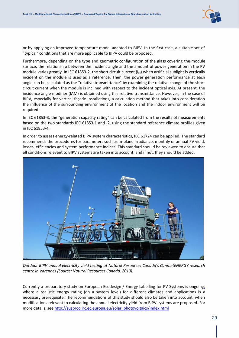
In order to assess energy-related BIPV system characteristics, IEC 61724 can be applied. The standard
recommends the procedures for parameters such as in-plane irradiance, monthly or annual PV yield,
losses, efficiencies and system performance indices. This standard should be reviewed to ensure that
all conditions relevant to BIPV systems are taken into account, and if not, they should be added.
Outdoor BIPV annual electricity yield testing at Natural Resources Canada’s CanmetENERGY research centre in Varennes (Source: Natural Resources Canada, 2019).
Currently a preparatory study on European Ecodesign / Energy Labelling for PV Systems is ongoing,
where a realistic energy rating (on a system level) for different climates and applications is a
necessary prerequisite. The recommendations of this study should also be taken into account, when
modifications relevant to calculating the annual electricity yield from BIPV systems are proposed. For
more details, see http://susproc.jrc.ec.europa.eu/solar_photovoltaics/index.html
Task 15 – Multifunctional Characterisation of BIPV – Proposed Topics for Future International Standardisation Activities
30
The proposals above are intended primarily as generic procedures that are applicable to different
types of BIPV modules and systems. When the annual electricity yield of a specific BIPV system is to
be predicted and/or optimized, a much more detailed approach, that also takes the effect of the
building surroundings explicitly into account, is recommended [11].
3.1.5 Electrical safety
3.1.5.1 Large module dimensions
Beside performance, safety-related restrictions, such as the maximum number of series-connected
cells within a sub-string protected by a parallel bypass-diode, must be considered [4], [6]. As the
maximum number of cells per substring depends on the reverse bias operating conditions of cells,
variations between cell technologies and within production lots of the same cell type must be taken
into account.
Typical conventional modules have 60 or 72 cells in 3 substrings, i.e. 20 or 24 cells covered by one
bypass diode. In building applications the maximum number of cells per substring may limit the total
dimension of photovoltaic elements. The currently valid hot-spot test procedures in IEC 61215-2 will
change slightly in the new Edition 2, because of corrections of some errors and ambiguous wording
from the previous edition of 2016. Nevertheless, there is still – as stated in [4] more than twenty
years ago, a lack of information on reverse cell characteristics and statistics that shall be provided by
the manufacturers. This could be overcome by trying to start a NP (New Work Item Proposal) within
IEC TC82 WG8 (crystalline) cells for in-line cell testing during production or simply by specifying
relevant information to be included in PV cell data sheets.
3.2 Mechanical
3.2.1 Encapsulant adherence
See Table above
3.2.2 Deformation under load
See Table above and elaboration below
In module testing only a pass/fail on specified mechanical load is included. Properties like
deformation of modules under a given mechanical load, depending on size and mounting conditions,
are needed as an input to check whether local requirements are met.
3.2.3 Post-breakage integrity
See Table above
3.2.4 Resistance to thermal stress
See Table above
3.2.5 Resistance to vibrations
See Table above regarding mechanical stability and elaborations below.
It may not be possible to pack large modules or prefabricated roof or façade elements with
integrated PV modules for transport from the factory to the building as carefully as is normally done
today for conventional PV modules. This will mean additional stress due to vibrations and mechanical
shocks, which will challenge the mechanical integrity of cells and modules. According to [17], the
Task 15 – Multifunctional Characterisation of BIPV – Proposed Topics for Future International Standardisation Activities
31
quasi-static application of very high distributed pressures as required by qualification standards is not
sufficient if we are interested in evaluating the actual degradation rate and possibly inferring the
lifetime of produced PV modules. In fact, other unexpected forms of damage, like fatigue
degradation are indeed possible due to the composite structure of the module and can be induced
by very common sub-critical loads like vibrations due to transportation or wind gusts, phenomena
that have not yet been characterized.
Until more appropriate methods to assess this are developed, products’ ability to withstand this stress can be evaluated by applying the current IEC standard, IEC 60721-3-2:2018, which specifies
vibration tests for transport of construction products. Electroluminescence and I-V characteristic
measurements are used for diagnosis.
3.3 Fire safety
See Table above and elaboration below
Laukamp et al [39] in 2013 presented a summary of some 180 incidents of fire or heat damage
caused by PV systems. Installation errors and faulty components, mainly inverters and junction
boxes, were the main causes of fire. The report concludes that the risk for a fire incident is 20 times
higher in a BIPV system than for BAPV. Since then, these alarming results have neither been verified
nor questioned by later studies, which indicates an urgent need for further research. For reasons that
have been explained in Sections 2.2.6, 2.3.1 and 2.3.7, BIPV does unquestionably exhibit some
features that increase the risk of fire. In view of the events and the studies carried out so far, the fire
risk for photovoltaic systems is evidently non-negligible and must be addressed to prevent injury to
people and economic losses. A study conducted in 2017 [34] shows three main domains that can be
further developed and investigated:
(i) Testing methods and procedures
(ii) Monitoring during operating conditions
(iii) Clear regulatory framework
A Norwegian review of standards and requirements [40] points out that the Swedish and Norwegian
building codes have no other requirements currently applicable to roof-applied or roof-integrated PV
than those defined in the EN 13501-5 and CEN/TS 1187:2012, method 2. The report concludes that
this is far from sufficient and that the UL 1703 with its referenced UL 790 is the most appropriate
currently existing test method for roof-integrated or roof-applied PV. The reason is that this standard
provides methods to test the combination of roof covering materials, mounting systems and PV
modules. The UL was recently harmonized to the IEC 61730 and has been replaced by UL 61730,
which complies with the national US electrical code. It thus appears that the UL 61730 should be the
basis for further development of methods, standards, requirements and guidelines aimed to assess
the fire properties and prevent the corresponding fire risks of PV, either applied to or integrated into
roofs.
For facades, the Norwegian report suggests that solar cells should be treated like other external
façade materials with a view to external fire stress and the risk of fire spreading in cavities behind the
outer façade. For most cases, a façade of solar cells will in principle be similar to another ventilated
facade. An additional factor for solar cells is that there are many electrical connections, and thus
potential ignition sources, inside the cavity behind the PV modules. The challenge here lies in the fact
that the regulations for fire spreading in façades are under development, and that it is therefore not
clear which requirements are to be placed on solar modules mounted vertically as the outer skin of a
façade.
Task 15 – Multifunctional Characterisation of BIPV – Proposed Topics for Future International Standardisation Activities
32
The treatment of fire resistance performance in BIPV varies, depending on the region and country.
Past studies of BIPV fire safety are cited for reference [32], [33]. In these studies, it was shown that
the glass unit and BIPV module have the same performance when exposed to fire. An experiment
was carried out using a heating furnace in accordance with a JIS standard and the heating curve of
ISO 834. Also, experiments were conducted with the PV modules connected to a load device in order
to evaluate the performance in use. It was clarified by the experimental result in accordance with the
JIS standard and heating curve of ISO 834 that the tested BIPV module has the same flame insulation
property as conventional fire protection glass. However, there are many other configurations of BIPV
modules for which this is NOT the case.
It is recognised that there is a need for modification of standards concerning many aspects of fire
safety but detailed proposals for modification exceed the scope of this report. Once it is published,
further guidance may be given by IEC TR 63226, a technical report currently under development that
discusses fire prevention measures during the design, installation, commissioning and maintenance
of PV systems (including BIPV) on buildings.
3.4 Optical / thermal
3.4.1 Transmittance / reflectance
See Table above and elaboration in following paragraph.
The optical characterization of BIPV modules can be based on the international standard ISO 9050,
which is equivalent (but not identical) to the EN 410 standard that is referenced in EN 50583. These
standards specify the methodology for determining the luminous and solar characteristics of glazing
in buildings. For partly transparent BIPV products that utilize flat glass or laminates, the overall
optical properties can be determined by first measuring the optical properties of the part without
cells in the laminate and then measuring the part that contains cells. An optical model can then be
applied to calculate the weighted average value, following the guidelines of ISO 15099. When the
weighted average value is declared, the section of the BIPV module to which it applies should be
clearly stated. In the case of monolithic thin-film semi-transparent BIPV modules with a
homogeneous appearance, an average representative area should be considered.
The dependence of the optical properties on the angle of incidence should also be taken into
account, e.g. by specifying transmittance and reflectance at an incidence angle of 60°.
For translucent BIPV modules, current standards (e.g. ISO 9050) do not provide sufficient information
on how to measure the optical properties of a product that includes a scattering layer such as glass,
interlayer, laminate or photovoltaic thin film technology [35]. As the problem of characterising
translucent products is also common among “conventional building products”, the relevant standards should be modified. These standards would then be applicable also to translucent BIPV
products.
It must be remembered that if a BIPV module includes a coloured element such as ceramic frit on the
glass cover or a coloured encapsulant material, the optical properties must be determined on the
coloured BIPV module. It is incorrect to use the optical properties of the uncoloured PV module in
this case.
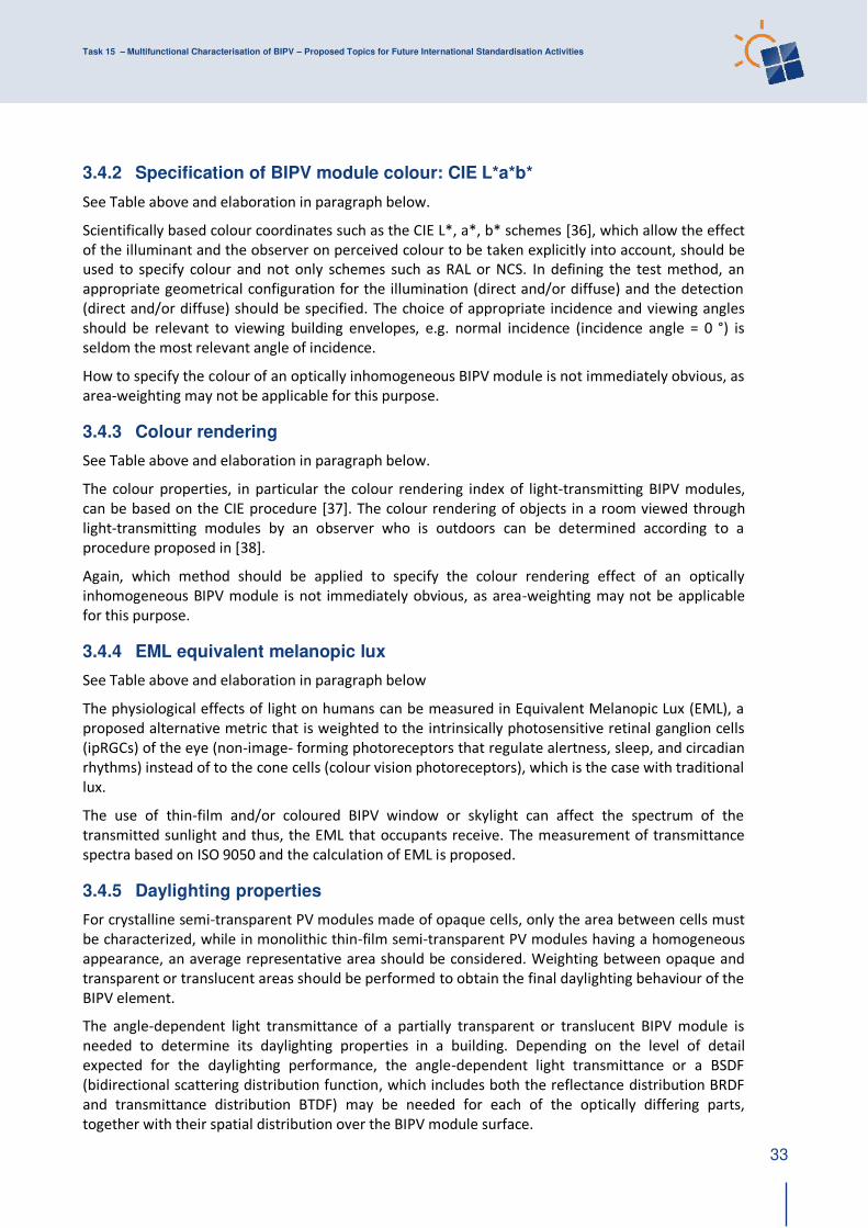
Task 15 – Multifunctional Characterisation of BIPV – Proposed Topics for Future International Standardisation Activities
33
3.4.2 Specification of BIPV module colour: CIE L*a*b*
See Table above and elaboration in paragraph below.
Scientifically based colour coordinates such as the CIE L*, a*, b* schemes [36], which allow the effect
of the illuminant and the observer on perceived colour to be taken explicitly into account, should be
used to specify colour and not only schemes such as RAL or NCS. In defining the test method, an
appropriate geometrical configuration for the illumination (direct and/or diffuse) and the detection
(direct and/or diffuse) should be specified. The choice of appropriate incidence and viewing angles
should be relevant to viewing building envelopes, e.g. normal incidence (incidence angle = 0 °) is
seldom the most relevant angle of incidence.
How to specify the colour of an optically inhomogeneous BIPV module is not immediately obvious, as
area-weighting may not be applicable for this purpose.
3.4.3 Colour rendering
See Table above and elaboration in paragraph below.
The colour properties, in particular the colour rendering index of light-transmitting BIPV modules,
can be based on the CIE procedure [37]. The colour rendering of objects in a room viewed through
light-transmitting modules by an observer who is outdoors can be determined according to a
procedure proposed in [38].
Again, which method should be applied to specify the colour rendering effect of an optically
inhomogeneous BIPV module is not immediately obvious, as area-weighting may not be applicable
for this purpose.
3.4.4 EML equivalent melanopic lux
See Table above and elaboration in paragraph below
The physiological effects of light on humans can be measured in Equivalent Melanopic Lux (EML), a
proposed alternative metric that is weighted to the intrinsically photosensitive retinal ganglion cells
(ipRGCs) of the eye (non-image- forming photoreceptors that regulate alertness, sleep, and circadian
rhythms) instead of to the cone cells (colour vision photoreceptors), which is the case with traditional
lux.
The use of thin-film and/or coloured BIPV window or skylight can affect the spectrum of the
transmitted sunlight and thus, the EML that occupants receive. The measurement of transmittance
spectra based on ISO 9050 and the calculation of EML is proposed.
3.4.5 Daylighting properties
For crystalline semi-transparent PV modules made of opaque cells, only the area between cells must
be characterized, while in monolithic thin-film semi-transparent PV modules having a homogeneous
appearance, an average representative area should be considered. Weighting between opaque and
transparent or translucent areas should be performed to obtain the final daylighting behaviour of the
BIPV element.
The angle-dependent light transmittance of a partially transparent or translucent BIPV module is
needed to determine its daylighting properties in a building. Depending on the level of detail
expected for the daylighting performance, the angle-dependent light transmittance or a BSDF
(bidirectional scattering distribution function, which includes both the reflectance distribution BRDF
and transmittance distribution BTDF) may be needed for each of the optically differing parts,
together with their spatial distribution over the BIPV module surface.
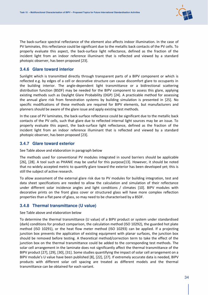
Task 15 – Multifunctional Characterisation of BIPV – Proposed Topics for Future International Standardisation Activities
34
The back-surface spectral reflectance of the element also affects indoor illumination. In the case of
PV laminates, this reflectance could be significant due to the metallic back contacts of the PV cells. To
properly evaluate this aspect, the back-surface light reflectance, defined as the fraction of the
incident light from an indoor reference illuminant that is reflected and viewed by a standard
photopic observer, has been proposed [23].
3.4.6 Glare toward interior
Sunlight which is transmitted directly through transparent parts of a BIPV component or which is
reflected e.g. by edges of a cell or decorative structure can cause discomfort glare to occupants in
the building interior. The angle-dependent light transmittance or a bidirectional scattering
distribution function (BSDF) may be needed for the BIPV component to assess this glare, applying
existing methods such as Daylight Glare Probability (DGP) [24]. A practicable method for assessing
the annual glare risk from fenestration systems by building simulation is presented in [25]. No
specific modifications of these methods are required for BIPV elements, but manufacturers and
planners should be aware of the glare issue and apply existing test methods.
In the case of PV laminates, the back-surface reflectance could be significant due to the metallic back
contacts of the PV cells, such that glare due to reflected internal light sources may be an issue. To
properly evaluate this aspect, the back-surface light reflectance, defined as the fraction of the
incident light from an indoor reference illuminant that is reflected and viewed by a standard
photopic observer, has been proposed [23].
3.4.7 Glare toward exterior
See Table above and elaboration in paragraph below
The methods used for conventional PV modules integrated in sound barriers should be applicable
[26], [28]. A tool such as PHANIE may be useful for this purpose[13]. However, it should be noted
that no widely accepted metric to quantify glare toward the exterior has been developed yet; this is
still the subject of active research.
To allow assessment of the external glare risk due to PV modules for building integration, test and
data sheet specifications are needed to allow the calculation and simulation of their reflectance
under different solar incidence angles and light conditions / climates [10]. BIPV modules with
decorative prints on the front glass cover or structured glass will have more complex reflection
properties than a flat pane of glass, so may need to be characterised by a BSDF.
3.4.8 Thermal transmittance (U value)
See Table above and elaboration below
To determine the thermal transmittance (U value) of a BIPV product or system under standardised
(dark) conditions for product comparison, the calculation method (ISO 10292), the guarded hot plate
method (ISO 10291), or the heat flow meter method (ISO 10293) can be applied. If a projecting
junction box prevents the application of existing equipment with planar surfaces, the junction box
should be removed before testing. A theoretical method/correction term to take the effect of the
junction box on the thermal transmittance could be added to the corresponding test methods. The
solar cell arrangement in the laminate does not significantly affect the thermal transmittance of the
BIPV product [27], [29], [30], [31]. Some studies quantifying the impact of solar cell arrangement on a
BIPV module’s U value have been published [8], [22], [27]. If extremely accurate data is needed, BIPV
products with different solar cell spacing are treated as different models and the thermal
transmittance can be obtained for each variant.
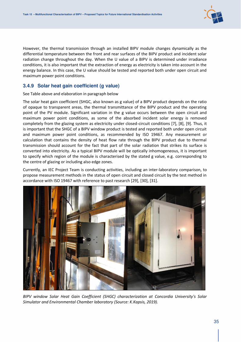
Task 15 – Multifunctional Characterisation of BIPV – Proposed Topics for Future International Standardisation Activities
35
However, the thermal transmission through an installed BIPV module changes dynamically as the
differential temperature between the front and rear surfaces of the BIPV product and incident solar
radiation change throughout the day. When the U value of a BIPV is determined under irradiance
conditions, it is also important that the extraction of energy as electricity is taken into account in the
energy balance. In this case, the U value should be tested and reported both under open circuit and
maximum power point conditions.
3.4.9 Solar heat gain coefficient (g value)
See Table above and elaboration in paragraph below
The solar heat gain coefficient (SHGC, also known as g value) of a BIPV product depends on the ratio
of opaque to transparent areas, the thermal transmittance of the BIPV product and the operating
point of the PV module. Significant variation in the g value occurs between the open circuit and
maximum power point conditions, as some of the absorbed incident solar energy is removed
completely from the glazing system as electricity under closed-circuit conditions [7], [8], [9]. Thus, it
is important that the SHGC of a BIPV window product is tested and reported both under open circuit
and maximum power point conditions, as recommended by ISO 19467. Any measurement or
calculation that contains the density of heat flow rate through the BIPV product due to thermal
transmission should account for the fact that part of the solar radiation that strikes its surface is
converted into electricity. As a typical BIPV module will be optically inhomogeneous, it is important
to specify which region of the module is characterised by the stated g value, e.g. corresponding to
the centre of glazing or including also edge zones.
Currently, an IEC Project Team is conducting activities, including an inter-laboratory comparison, to
propose measurement methods in the status of open circuit and closed circuit by the test method in
accordance with ISO 19467 with reference to past research [29], [30], [31].
BIPV window Solar Heat Gain Coefficient (SHGC) characterization at Concordia University's Solar
Simulator and Environmental Chamber laboratory (Source: K.Kapsis, 2019).
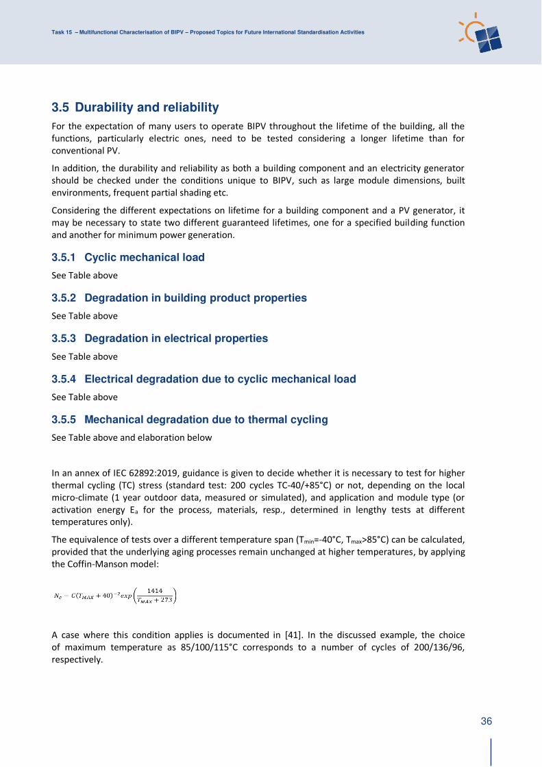
Task 15 – Multifunctional Characterisation of BIPV – Proposed Topics for Future International Standardisation Activities
36
3.5 Durability and reliability
For the expectation of many users to operate BIPV throughout the lifetime of the building, all the
functions, particularly electric ones, need to be tested considering a longer lifetime than for
conventional PV.
In addition, the durability and reliability as both a building component and an electricity generator
should be checked under the conditions unique to BIPV, such as large module dimensions, built
environments, frequent partial shading etc.
Considering the different expectations on lifetime for a building component and a PV generator, it
may be necessary to state two different guaranteed lifetimes, one for a specified building function
and another for minimum power generation.
3.5.1 Cyclic mechanical load
See Table above
3.5.2 Degradation in building product properties
See Table above
3.5.3 Degradation in electrical properties
See Table above
3.5.4 Electrical degradation due to cyclic mechanical load
See Table above
3.5.5 Mechanical degradation due to thermal cycling
See Table above and elaboration below
In an annex of IEC 62892:2019, guidance is given to decide whether it is necessary to test for higher
thermal cycling (TC) stress (standard test: 200 cycles TC-40/+85°C) or not, depending on the local
micro-climate (1 year outdoor data, measured or simulated), and application and module type (or
activation energy Ea for the process, materials, resp., determined in lengthy tests at different
temperatures only).
The equivalence of tests over a different temperature span (Tmin=-40°C, Tmax>85°C) can be calculated,
provided that the underlying aging processes remain unchanged at higher temperatures, by applying
the Coffin-Manson model:
A case where this condition applies is documented in [41]. In the discussed example, the choice
of maximum temperature as 85/100/115°C corresponds to a number of cycles of 200/136/96,
respectively.

Task 15 – Multifunctional Characterisation of BIPV – Proposed Topics for Future International Standardisation Activities
37
However, as it is not clear whether the aging processes that affect mechanical properties remain
unchanged over the wider temperature range that can be experienced by installed BIPV modules, it
is recommended that research be done to identify whether this criterion (no new ageing processes at
higher temperatures) is indeed met. On the basis of this information, a decision can be made as to
whether it is adequate simply to increase the number of testing cycles or whether the tested
temperature range itself must be extended.
3.5.6 Thermal cycling
See Table above and elaboration below
Due to the greater number of thermal cycles that are often experienced in practice due to more
frequent shading of BIPV systems than conventional PV systems, the number of thermal cycling
should be increased for this reason.
3.5.7 Thermal stress
See Table above and elaboration below
In order to characterise the effect of surface decoration, causing different transmittance in front of
different cells, on the PV module’s temperature, an equivalent PV module, with identical PV cells and design, but with no decoration patterns, should be supplied by the manufacturer together with the
decorated module. Existing partial shading testing procedures included in the standards for general
PV modules (IEC 61215) can be applied, but in this case the “shaded condition” would be the decorated module and the “unshaded condition” the module without decoration.
In general, higher operating temperature of BIPV modules and its components may occur due to
restricted cooling conditions. Therefore, check for module operating temperatures, taking
application and climate into account.
If the 98th-% quantile temperature (175.2 h of 8760 h/a) is
- above 70°C, but not greater than 80°C → modify tests according to IEC TS
63126, Temperature Level 1,
- above 80°C but not greater than 90°C → Temperature Level 2 modification.
It was observed that some bypass diodes with low breakdown voltage may be affected by a thermal
runaway effect: When the diode is operating as intended, due to shaded module parts and under
high temperature, and the shading object suddenly disappears, the diode has to return to normal
reverse-bias conditions. However, at a high diode junction temperature, the residual reverse bias
current may be high enough to further heat the diode, resulting in a thermal runaway. As a high(er)
temperature of the junction box and frequent shading may occur in BIPV applications, it is
recommended to consider making the thermal runaway test of IEC 62979 mandatory for modules
used in the built environment.
Task 15 – Multifunctional Characterisation of BIPV – Proposed Topics for Future International Standardisation Activities
38
3.6 Testing of curved elements
When testing curved PV modules, it should be considered that once installed, they will receive
diffuse irradiance from a wider solid angle than flat modules. Thus, it is convenient to test them
under natural sunlight to better reproduce these conditions. Curved BIPV modules commonly have
an extrinsic curvature and specular symmetry in one axis. The higher the curvature, the larger the
solid angle seen by the surface, and the more the power output depends on string orientation and
solar position under clear sky conditions.
A critical issue is therefore the position setting of the module with reference to the solar direction. A
possible approach is to place the module in such a way that the normal to the surface in the central
section is directed to the position of the sun, i.e., oriented such that the sun falls perpendicularly
onto the surface at its midpoint. Also, the albedo should be specified.
Tests of mechanical, thermal and optical properties may also need to be modified where the existing
test equipment is designed for test objects with planar geometry.
Task 15 – Multifunctional Characterisation of BIPV – Proposed Topics for Future International Standardisation Activities
39
4 SUMMARY
The challenges of additional requirements resulting from the use of PV modules in the built
environment have not yet been overcome. The most pressing challenge is to simplify and generalize
the tests and requirements for BIPV products to allow easier and wider international market
introduction.
After identifying features of BIPV modules that call for modifications of existing standards, proposals
for modified or new tests and calculation procedures have been collected in this report.
The combination of tests used today in the PV world and in the construction world is one approach
that can be followed to reduce the complexity and number of tests required for BIPV modules and
systems. This and other approaches to multi-functional characterization of BIPV will be addressed
internationally at the pre-normative level during the next phase of IEA-PVPS Task 15.
Task 15 – Multifunctional Characterisation of BIPV – Proposed Topics for Future International Standardisation Activities
40
5 REFERENCES
[1] Wilson, H.R. (ed.) et al., International definitions of “BIPV”, IEA PVPS Task 15, Report IEA-PVPS T15-
04: 2018, August 2018
[2] Eisenlohr, J., Wilson, H.R., Kuhn, T.E. Detailed Modelling of Building-Integrated Photovoltaics – From
Component and Environmental Data to the System Output, Conf. Proc.33rd European Photovoltaic
Solar Energy Conference and Exhibition, 2017, pp. 2118 -2122, ISBN 3-936338-47-7, DOI:
10.4229/EUPBSEC20172017-6DO.11.1
[3] Martín, N., Ruiz, J.M. Annual Angular Reflection Losses in PV Modules, Prog. Photovolt: Res. Appl.
2005; 13:75–84
[4] Sprenger, W. Electricity yield simulation of complex BIPV systems, Ph.D. thesis, TU Delft, 2013, ISBN:
978-3-8396-0606-3, Fraunhofer Verlag, URL: http://verlag.fraunhofer.de
[5] Herrmann, W., Adrian, M., Wiesner, W. Operational behavior of commercial solar cells under reverse
biased conditions, 2nd WCPEC, Vienna, 1998, pp. 2357-2359
[6] Bothe, K., Ramspeck, K., Hinken, D., Schinke, C., Schmidt, J., Herlufsen, S., Brendel, R., Bauer, J.,
Wagner, J.-M., Zakharov, N., Breitenstein, O. Luminescence emission from forward- and reverse-
biased multicrystalline silicon solar cells. Journal of Applied Physics 106 (2009), 104510 p.1-8,
doi:10.1063/1.3256199.
[7] Baenas, T., Machado, M., 2017. On the analytical calculation of the solar heat gain coefficient of a
BIPV module. Energy Build. 151, 146–156.
[8] Kapsis, K., Athienitis, A.K., Harrison, S.J., 2017. Determination of solar heat gain coefficient for semi-
transparent photovoltaic windows: an experimental study. ASHRAE Trans. 123.
[9] Olivieri, L., Frontini, F., Polo-López, C., Pahud, D., Caamaño-Martín, E., 2015. G-value indoor
characterization of semi-transparent photovoltaic elements for building integration: New equipment
and methodology. Energy Build. 101, 84–94.
[10] Schregle, R., Renken, C., Wittkopf, S. Spatio-Temporal Visualisation of Reflections from Building
Integrated Photovoltaics, Buildings 2018, 8(8), 101, https://doi.org/10.3390/buildings8080101
[11] W. Sprenger, H.R. Wilson, T.E. Kuhn, Electricity yield simulation for the building-integrated
photovoltaic system installed in the main building roof of the Fraunhofer Institute for Solar Energy
Systems ISE, Solar Energy 135 (2016) 633 - 643
[12] Koehl, M., Hamperl, S., Heck, M. Effect of thermal insulation of the back side of PV modules on the
module temperature. Prog. Photovolt. Vol.24 (2016), Issue 9, P. 1194-1199.
https://doi.org/10.1002/pip.2773
[13] PHANIE - Calculation of solar exposure and lighting design http://www.cstb.fr/dae/en/nos-produits-
et-formations/outils-de-calcul/phanie.html
[14] Mon, G.R., Wen, L.C., Sugimura, R.S., Ross, Jr., R.G. Reliability studies of photovoltaic module
insulation systems, 1989 IEEE - CH2788-8/89/0000-0324 pp. 324-329
[15] Report IEA-PVPS T13-01:2014: M. Köntges, S. Kurtz, C. Packard, U. Jahn, K. A. Berger, K. Kato, T.
Friesen, H. Liu, M. Van Iseghem, J. Wohlgemuth, D. Miller, M. Kempe, P. Hacke, F. Reil, N. Bogdanski,
W. Herrmann, C. Buerhop-Lutz, G. Razongles, and G. Friesen, Review of Failures of Photovoltaic
Modules. IEA 2014, 114 p. see http://www.iea-pvps.org/index.php?id=275
[16] Report IEA-PVPS T13-09:2017: M. Köntges, G. Oreski, U. Jahn, M. Herz, P. Hacke, K.-A. Weiss, G.
Razongles, M. Paggi, D. Parlevliet, T. Tanahashi, R.H. French, M. Richter, C. Tjengdrawira, A. Morlier,
H. Li, L.-E. Perret-Aebi, K..A. Berger, G. Makrides, W. Herrmann Assessment of Photovoltaic Module
Failures in the Field. IEA 2017, 123p. see http://www.iea-pvps.org/index.php?id=435
[17] Paggi, M. et al., Fatigue degradation andelectric recovery in silicon solar cells embedded in
photovoltaic modules. SCIENTIFIC REPORTS | 4:4506 | DOI: 10.1038/srep04506
Task 15 – Multifunctional Characterisation of BIPV – Proposed Topics for Future International Standardisation Activities
41
[18] Luo, W., Khoo, Y.S., Hacke, P., Naumann, V., Lausch, D., Harvey, S.P., Singh, J.P., Chai, J., Wang, Y.,
Aberle, A.G., Ramakrishna, S. Potential-induced degradation in photovoltaic modules: a critical
review. Energy Environ. Sci., 10 (2017), p. 43-68. DOI: 10.1039/C6EE02271E
[19] Oreski, G. Encapsulant materials and degradation effects - Requirements for encapsulants, new
materials, research trends. IEA-PVPS Task 13 Open Workshop, Freiburg, 2014-04
[20] Schulze, S-H., Apel, A., Meitzner, R., Schak, M., Ehrich, C., Schneider, J. Influence of Polymer
Properties on Potential-Induced Degradation of PV-Modules. 28th EU-PVSEC, Paris 2013, p.503-507
[21] OVE-Richtlinie R 11-3:2016 Blendung durch Photovoltaikanlagen (Glare from Photovotaic systems).
18p.
[22] Sánchez-Palencia, P., Martín-Chivelet, N., Chenlo, F. Modeling temperature and thermal
transmittance of building integrated photovoltaic modules, Solar Energy, (2019) Volume 184, Pages
153-161
[23] Moralejo-Vázquez, F. J., Martín-Chivelet, N., Olivieri, L., Caamaño-Martín, E. Luminous and solar
characterization of PV modules for building integration, Energy Build., vol. 103, pp. 326–337, Sep.
2015.
[24] Wienold, J., Iwata, T., Sarey Khanie, M., Erell, E., Kaftan, E., Rodriguez, R.G., Yamin Garreton, J.A.,
Tzempelikos, T., Konstantzos, I., Christoffersen, J., Kuhn, T.E., Pierson, C., Andersen, M. Cross-
validation and robustness of daylight glare metrics. Lighting Res. Technol. (2019) pp. 1–31
[25] Abravesh,M., Bueno, B., Heidaric, S., Kuhn, T.E. A method to evaluate glare risk from operable
fenestration systems throughout a year. Building and Environment, 160 (2019) 106213
[26] Barrett, S., Glare Factor: Solar Installations And Airports, Solar Industry, Volume 6, Number 5, June
2013. http://www.solarindustrymag.com/issues/SI1306/FEAT_02_Glare_Factor.html
[27]Frontini, F., Chatzipanagi, A., Virtuani, A. BIPV-temp: A demonstrative Building Integrated
Photovoltaic installation, Applied Energy, http://dx.doi.org/10.1016/j.apenergy.2016.03.097
[28] Sandia Solar Glare Mapping Tools: https://share.sandia.gov/phlux
[29] Ishii, H., Thermal Performance (G-Value and U-Value) 2017 - Evaluation of BIPV Applied to Glass
Façade. In 33rd European Photovoltaic Solar Energy Conference and Exhibition Conference.
Amsterdam.
[30] Ishii, H., Kondo, M., Saito , M., Hayashi, M and Saito, H. 2018 -Thermal Properties for BIPV in Glass
Façade. Experimental Results of Thermal Transmittance and Solar Heat Gain Coefficient for Crystal
Silicon PV Module. Grand Renewable Energy 2018 International Conference and Exhibition.
Yokohama. Japan
[31] Ishii, H., Evaluation of Thermal Properties for BIPV in Façade Part 2 Experimental Results of G value
for Crystal Silicon BIPV Module according to ISO 19467, 35th European Photovoltaic Solar Energy
Conference and Exhibition Conference. Brussels.
[32] Ishii, H., Kondo, M., Saito , M., Nakajima, A, Hayashi, M and Saito, H. Experimental Study on BIPV
Module of Closed Circuit Situation Exposed to Fire. Grand Renewable Energy 2018 International
Conference and Exhibition. Yokohama. Japan
[33] Ishii, H., Experimental Study on BIPV Module during Power Generation Exposed to Fire 35th European
Photovoltaic Solar Energy Conference and Exhibition Conference. Brussels.
[34] Bonomo, P., E. Saretta, F. Frontini, M. Caccivio, G. Bellenda, G. Manzini, P. Cancelliere, Fire Safety of
PV Modules and Buildings: Overviews, Bottlenecks and Hints, 33rd European Photovoltaic Solar
Energy Conference and Exhibition, 10.4229/EUPVSEC20172017-6BV.1.37
[35] Wilson, H.R., Elstner, M. Spot Landing: Determining the Light and Solar Properties of Fritted and
Coated Glass. Challenging Glass 6, Delft, 2018. ISBN 978-94-6366-044-0,
https://doi.org/10.7480/cgc.6.2134
[36] CIE International Commission on Illumination, Colorimetry , CIE 015:2018
[37] CIE International Commission on Illumination, Method of Measuring and Specifying Colour Rendering
Properties of Light Sources, CIE 13.31995. (1995)

Task 15 – Multifunctional Characterisation of BIPV – Proposed Topics for Future International Standardisation Activities
42
[38] Kuhn, T.E., Wilson, H.R., Hanek, J., Santamouris, M. Raout-in: Color rendering of objects in a daylit
room viewed fromoutdoors. Energy and Buildings 118 (2016) 93–98
[39] Laukamp, H. et al. PV fire hazard – Analysis and assessment of fire incidents, 28th EU-PVSEC, 2013,
Paris
[40] R Fjellgaard Mikalsen et al. Energieffektive bygg og brannsikkerhet (Energy-efficient building and fire
safety). RISE-rapport 2019:02
[41] N. Bosco, T. Silverman, and S. Kurtz, Climate Specific Solder Thermal Fatigue Damage in PV Modules,
Microelectronics Reliability, vol. 62, pp. 124-129, July 2016

Task 15 – Multifunctional Characterisation of BIPV – Proposed Topics for Future International Standardisation Activities
43
6 REFERENCED STANDARDS
CEN/TS 1187:2012.Test methods for external fire exposure to roofs
EN 410:2011. Glass in building - Determination of luminous and solar characteristics of glazing.
EN 13501-5:2016 Fire classification of construction products and building elements – Part 5:
Classification using data from external fire exposure to roofs tests.
EN 50583-1:2016. Photovoltaics in buildings - BIPV modules.
EN 50583-2:2016. Photovoltaics in buildings - BIPV systems.
ENV 1187:2002, Parts 1 to 4. Test methods for external fire exposure to roofs
IEC 60721-3-2:2018 Classification of environmental conditions - Part 3-2: Classification of groups of
environmental parameters and their severities - Transportation and Handling
IEC 60891 Photovoltaic devices. Procedures for temperature and irradiance corrections to measured
current-voltage characteristics
IEC 60904-1:2006, Photovoltaic devices - Part 1 : Measurement of photovoltaic current-voltage
characteristics
IEC 60904-5, Photovoltaic devices - Part 5 : determination of the equivalent cell temperature (ECT) of
photovoltaic (PV) devices by the open-circuit voltage method
IEC 61215-1:2016. Terrestrial photovoltaic (PV) modules - Design qualification and type approval -
Part 1: Test requirements.
IEC 61215-1-1:2016. Terrestrial photovoltaic (PV) modules - Design qualification and type approval -
Part 1-1: Special requirements for testing of crystalline silicon photovoltaic (PV) modules.
IEC 61215-1-2:2016. Terrestrial photovoltaic (PV) modules - Design qualification and type approval -
Part 1-2: Special requirements for testing of thin-film Cadmium Telluride (CdTe) based
photovoltaic (PV) modules.
IEC 61215-1-3:2016. Terrestrial photovoltaic (PV) modules - Design qualification and type approval -
Part 1-3: Special requirements for testing of thin-film amorphous silicon based photovoltaic (PV)
modules.
IEC 61215-1-1:2016. Terrestrial photovoltaic (PV) modules - Design qualification and type approval -
Part 1-1: Special requirements for testing of crystalline silicon photovoltaic (PV) modules.
IEC 61215-2:2016. Terrestrial photovoltaic (PV) modules - Design qualification and type approval -
Part 2: Test procedures.
IEC 61724: Photovoltaic system. Performance monitoring. Guidelines for measurement,data
exchange and analysis
IEC 61730-1:2016. Photovoltaic (PV) module safety qualification - Part 1: Requirements for
construction.
IEC 61730-2:2016. Photovoltaic (PV) module safety qualification - Part 2: Requirements for testing.
IEC 61853-1:2011. Photovoltaic modules. Determination of performance testing and energy rating.
Part 1. Irradiance and temperature performance measurement according to irradiance and
temperature. Power rating
Task 15 – Multifunctional Characterisation of BIPV – Proposed Topics for Future International Standardisation Activities
44
IEC 61853-2:2016. Photovoltaic (PV) module performance testing and energy rating - Part 2: Spectral
responsivity, incidence angle and module operating temperature measurements
IEC 61853-3:2018. Photovoltaic (PV) module performance testing and energy rating - Part 3: Energy
rating of PV modules
IEC 61853-4:2018. Photovoltaic (PV) module performance testing and energy rating - Part 4: Standard
reference climatic profiles
IEC 62788 series. Measurement procedures for materials used in photovoltaic modules
IEC 62790:2014. Junction boxes for photovoltaic modules - Safety requirements and tests
IEC 62852:2014. Connectors for DC-application in photovoltaic systems - Safety requirements and
tests
IEC 62892:2019. Extended thermal cycling of PV modules. Test procedure
IEC 62979:2017 Photovoltaic module – Bypass diode –Thermal runaway test
IEC 63092-1:2020 Photovoltaics in buildings – Part 1: Building integrated photovoltaic modules (The
CDV of this standard was accepted in January 2020. Publication of the standard is expected in
2020.)
IEC 63092-2:2020 Photovoltaics in buildings – Part 2: Building integrated photovoltaic systems (The
CDV of this standard was accepted in January 2020. Publication of the standard is expected in
2020.)
IEC TR 63226:2018 (CD) Solar photovoltaic energy systems - Managing fire risk related to
photovoltaic (PV) systems on buildings
IEC TS 60904-1-2:2019 Photovoltaic devices - Part 1-2: Measurement of current-voltage
characteristics of bifacial photovoltaic (PV) devices
IEC TS 62804-1:2015 (Ed. 1) Photovoltaic (PV) modules - Test methods for the detection of potential-
induced degradation - Part 1: Crystalline silicon
IEC TS 62915:2018 Photovoltaic (PV) modules - Retesting for type approval, design and safety
qualification
IEC TS 63126 Guidelines for qualifying PV modules, components and materials for operation at high
temperatures. Draft, publication of 1st ed. planned for 2020
ISO 834:1999. Fire-resistance tests - Elements of building construction (all parts).
ISO 9050:2003. Glass in building - Determination of light transmittance, solar direct transmittance,
total solar energy transmittance, ultraviolet transmittance and related glazing factors.
ISO 10291:1994. Glass in building - Determination of steady-state U values (thermal transmittance) of
multiple glazing - Guarded hot plate method.
ISO 10292:1994. Glass in building - Calculation of steady-state U values (thermal transmittance) of
multiple glazing.
ISO 10293:1997. Glass in building - Determination of steady-state U values (thermal transmittance) of
multiple glazing - Heat flow meter method.
ISO 15099:2003 Thermal performance of windows, doors and shading devices -- Detailed calculations
ISO 19467:2017. Thermal performance of windows and doors - Determination of solar heat gain
coefficient using solar simulator.

Task 15 – Multifunctional Characterisation of BIPV – Proposed Topics for Future International Standardisation Activities
45
ISO 19467-2:2020. Thermal performance of windows and doors - Determination of solar heat gain
coefficient using solar simulator – Part 2: Centre of glazing (publication expected in 2020)
UL 790. Standard Test Methods for Fire Tests of Roof Coverings, UL LLC, ulstd edition 8, Apr. 2004.
UL 1703:2015. Flat-plate photovoltaic modules and panels.
UL 61730 series – see IEC 61730

Task 15 – Multifunctional Characterisation of BIPV – Proposed Topics for Future International Standardisation Activities
46
7 ABBREVIATIONS AND ACRONYMS
AAMA American Architectural Manufacturers Association
AOI Angle of Incidence
BAPV Building-Attached Photovoltaic
BIM Building information modelling
BIPV Building-Integrated Photovoltaic
BS British Standards
BSDF Bi-directional Scattering Distribution Function
BRDF Bi-directional Reflectance Distribution Function
BTDF Bi-directional Transmittance Distribution Function
CEN European Committee for Standardization
CIE International Commission on Illumination
CSA Canadian Standards Association
DGP Daylight Glare Probability
Ea Activation energy
EC European Commission
ECT Equivalent Cell Temperature
EML Equivalent Melanopic Lux
EN European Standard
EVA Ethylene vinyl acetate
IAM Incidence Angle Modifier
IEA International Energy Agency
IEC International Electrotechnical Commission
IGU Insulating Glass Unit
ipRGC intrinsically photosensitive Retinal Ganglion Cell
IR Infrared
IS International Standard
Isc Short-circuit current
ISO International Organization for Standardization
I-V Current-voltage
JIS Japanese Industrial Standard
MPP Maximum Power Point
NAFS North American Fenestration Standard
NCS Natural Colour System
NOCT Nominal Operating Cell Temperature
NMOT Nominal Module Operating Temperature
NP New Work Item Proposal
PCE Power Conversion Equipment
PID Potential-Induced Degradation
pr Project (of standard)
PV Photovoltaic
PVPS Photovoltaic Power Systems Program

Task 15 – Multifunctional Characterisation of BIPV – Proposed Topics for Future International Standardisation Activities
47
RAL Reichsausschuss für Lieferbedingungen
SHGC Solar Heat Gain Coefficient
STC Standard Test Conditions
TC Technical Committee
TC Thermal Cycling
TCO Transparent Conductive Oxide
TR Technical Report
TS Technical Specification
UL Underwriters Laboratories
Voc Open-circuit voltage
WDMA Window & Door Manufacturers Association
WG Working Group
XML Extensible Markup Language
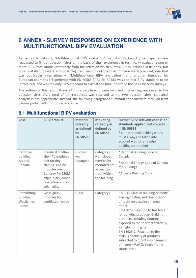
Task 15 – Multifunctional Characterisation of BIPV – Proposed Topics for Future International Standardisation Activities
48
8 ANNEX - SURVEY RESPONSES ON EXPERIENCE WITH MULTIFUNCTIONAL BIPV EVALUATION
As part of Activity C3, “Multifunctional BIPV evaluation”, in IEA-PVPS Task 15, participants were
requested to fill out questionnaires on the basis of their experience in technically evaluating one or
more BIPV installations (preferably from the selection which Subtask A has included in its book, but
other installations were also possible). Two versions of the questionnaire were provided, one that
was applicable internationally (“Multifunctional BIPV evaluation”) and another intended for European countries (“Experience with EN 50583”). As EN 50583 was the first BIPV standard to be
introduced, and was the only BIPV standard to exist at the time, it formed the basis for both surveys.
The authors of this report thank all those people who were involved in providing responses to the
questionnaires. As a total of ten responses was received to the two questionnaires, statistical
analysis is not appropriate. Instead, the following paragraphs summarize the answers received from
various participants for future reference.
8.1 Multifunctional BIPV evaluation
Case BIPV product Material
category
as defined
by
EN 50583
Mounting
category as
defined by
EN 50583
Further BIPV-relevant codes* or
standards applied, not covered
in EN 50583
* N.B. National building codes
must always be taken into
account – as for any other
building component
Camrose
building,
Alberta,
Canada
Standard off-the-
shelf PV modules
and racking
clamps. The PV
modules are
Conergy PH 250M
triple-black, mono-
crystalline silicon
solar cells.
Curtain
wall
(opaque)
Category C:
Non-sloped
(vertically)
mounted not
accessible
from within
the building
*National Building Code of
Canada
*National Energy Code of Canada
for Buildings
*Alberta Building Code
Retrofitting
building,
Wattignies,
France
Glass-glass
modules for
ventilated façade
Glass Category C EN 356, Glass in Building-Security
glazing-Testing and classification
of resistance against manual
attack.
EN 13823, Reaction to fire tests
for building products- Building
products excluding floorings
exposed to the thermal attack by
a single burning item.
EN 11925-2, Reaction to fire
tests-Ignitability of products
subjected to direct impingement
of flame – Part 2: Single-flame
source test.
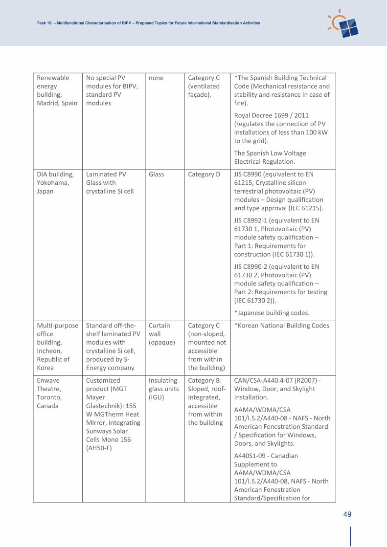
Task 15 – Multifunctional Characterisation of BIPV – Proposed Topics for Future International Standardisation Activities
49
Renewable
energy
building,
Madrid, Spain
No special PV
modules for BIPV,
standard PV
modules
none Category C
(ventilated
façade).
*The Spanish Building Technical
Code (Mechanical resistance and
stability and resistance in case of
fire).
Royal Decree 1699 / 2011
(regulates the connection of PV
installations of less than 100 kW
to the grid).
The Spanish Low Voltage
Electrical Regulation.
DIA building,
Yokohama,
Japan
Laminated PV
Glass with
crystalline Si cell
Glass Category D JIS C8990 (equivalent to EN
61215, Crystalline silicon
terrestrial photovoltaic (PV)
modules – Design qualification
and type approval (IEC 61215).
JIS C8992-1 (equivalent to EN
61730 1, Photovoltaic (PV)
module safety qualification –
Part 1: Requirements for
construction (IEC 61730 1)).
JIS C8990-2 (equivalent to EN
61730 2, Photovoltaic (PV)
module safety qualification –
Part 2: Requirements for testing
(IEC 61730 2)).
*Japanese building codes.
Multi-purpose
office
building,
Incheon,
Republic of
Korea
Standard off-the-
shelf laminated PV
modules with
crystalline Si cell,
produced by S-
Energy company
Curtain
wall
(opaque)
Category C
(non-sloped,
mounted not
accessible
from within
the building)
*Korean National Building Codes
Enwave
Theatre,
Toronto,
Canada
Customized
product (MGT
Mayer
Glastechnik): 155
W MGTherm Heat
Mirror, integrating
Sunways Solar
Cells Mono 156
(AH50-F)
Insulating
glass units
(IGU)
Category B:
Sloped, roof-
integrated,
accessible
from within
the building
CAN/CSA-A440.4-07 (R2007) -
Window, Door, and Skylight
Installation.
AAMA/WDMA/CSA
101/I.S.2/A440-08 - NAFS - North
American Fenestration Standard
/ Specification for Windows,
Doors, and Skylights.
A440S1-09 - Canadian
Supplement to
AAMA/WDMA/CSA
101/I.S.2/A440-08, NAFS - North
American Fenestration
Standard/Specification for
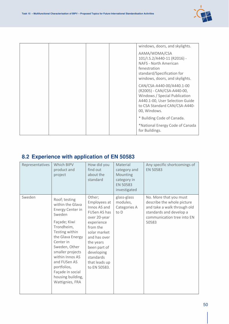
Task 15 – Multifunctional Characterisation of BIPV – Proposed Topics for Future International Standardisation Activities
50
windows, doors, and skylights.
AAMA/WDMA/CSA
101/I.S.2/A440-11 (R2016) -
NAFS - North American
fenestration
standard/Specification for
windows, doors, and skylights.
CAN/CSA-A440-00/A440.1-00
(R2005) - CAN/CSA-A440-00,
Windows / Special Publication
A440.1-00, User Selection Guide
to CSA Standard CAN/CSA-A440-
00, Windows.
* Building Code of Canada.
*National Energy Code of Canada
for Buildings.
8.2 Experience with application of EN 50583
Representatives Which BIPV
product and
project
How did you
find out
about the
standard
Material
category and
Mounting
category in
EN 50583
investigated
Any specific shortcomings of
EN 50583
Sweden Roof; testing
within the Glava
Energy Center in
Sweden
Façade; Kiwi
Trondheim,
Testing within
the Glava Energy
Center in
Sweden, Other
smaller projects
within Innos AS
and FUSen AS
portfolios,
Façade in social
housing building,
Wattignies, FRA
Other;
Employees at
Innos AS and
FUSen AS has
over 20-year
experience
from the
solar market
and has over
the years
been part of
developing
standards
that leads up
to EN 50583.
glass-glass
modules,
Categories A
to D
No. More that you must
describe the whole picture
and take a walk through old
standards and develop a
communication tree into EN
50583
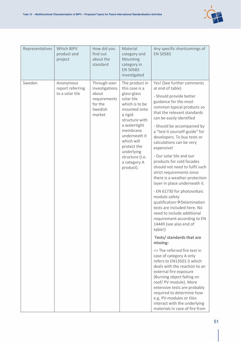
Task 15 – Multifunctional Characterisation of BIPV – Proposed Topics for Future International Standardisation Activities
51
Representatives Which BIPV
product and
project
How did you
find out
about the
standard
Material
category and
Mounting
category in
EN 50583
investigated
Any specific shortcomings of
EN 50583
Sweden
Anonymous
report referring
to a solar tile
Through own
investigations
about
requirements
for the
Swedish
market
The product in
this case is a
glass-glass
solar tile
which is to be
mounted onto
a rigid
structure with
a watertight
membrane
underneath it
which will
protect the
underlying
structure (I.e.
a category A
product).
Yes! (See further comments
at end of table)
- Should provide better
guidance for the most
common typical products so
that the relevant standards
can be easily identified
- Should be accompanied by
a “test it yourself-guide” for developers. To buy tests or
calculations can be very
expensive!
- Our solar tile and our
products for cold facades
should not need to fulfil such
strict requirements since
there is a weather protection
layer in place underneath it.
- EN 61730 for photovoltaic
module safety
qualification→Delamination
tests are included here. No
need to include additional
requirement according to EN
14449 (see also end of
table!)
Tests/ standards that are
missing:
=> The referred fire test in
case of category A only
refers to EN13501-5 which
deals with the reaction to an
external fire exposure
(Burning object falling on
roof/ PV module). More
extensive tests are probably
required to determine how
e.g. PV-modules or tiles
interact with the underlying
materials in case of fire from
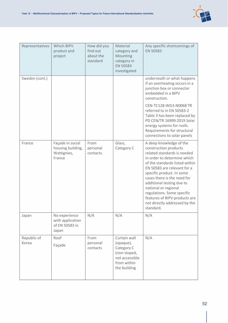
Task 15 – Multifunctional Characterisation of BIPV – Proposed Topics for Future International Standardisation Activities
52
Representatives Which BIPV
product and
project
How did you
find out
about the
standard
Material
category and
Mounting
category in
EN 50583
investigated
Any specific shortcomings of
EN 50583
Sweden (cont.) underneath or what happens
if an overheating occurs in a
junction box or connector
embedded in a BIPV
construction.
CEN-TC128-WG3-N0068 TR
referred to in EN 50583-2
Table 3 has been replaced by
PD CEN/TR 16999:2019 Solar
energy systems for roofs.
Requirements for structural
connections to solar panels
France Façade in social
housing building,
Wattignies,
France
From
personal
contacts.
Glass,
Category C
A deep knowledge of the
construction products
related standards is needed
in order to determine which
of the standards listed within
EN 50583 are relevant for a
specific product. In some
cases there is the need for
additional testing due to
national or regional
regulations. Some specific
features of BIPV products are
not directly addressed by the
standard.
Japan No experience
with application
of EN 50583 in
Japan
N/A N/A N/A
Republic of
Korea
Roof
Façade
From
personal
contacts
Curtain wall
(opaque),
Category C
(non-sloped,
not accessible
from within
the building
N/A
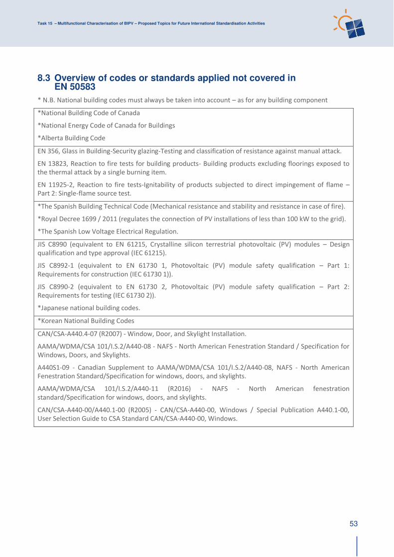
Task 15 – Multifunctional Characterisation of BIPV – Proposed Topics for Future International Standardisation Activities
53
8.3 Overview of codes or standards applied not covered in EN 50583
* N.B. National building codes must always be taken into account – as for any building component
*National Building Code of Canada
*National Energy Code of Canada for Buildings
*Alberta Building Code
EN 356, Glass in Building-Security glazing-Testing and classification of resistance against manual attack.
EN 13823, Reaction to fire tests for building products- Building products excluding floorings exposed to
the thermal attack by a single burning item.
EN 11925-2, Reaction to fire tests-Ignitability of products subjected to direct impingement of flame –
Part 2: Single-flame source test.
*The Spanish Building Technical Code (Mechanical resistance and stability and resistance in case of fire).
*Royal Decree 1699 / 2011 (regulates the connection of PV installations of less than 100 kW to the grid).
*The Spanish Low Voltage Electrical Regulation.
JIS C8990 (equivalent to EN 61215, Crystalline silicon terrestrial photovoltaic (PV) modules – Design
qualification and type approval (IEC 61215).
JIS C8992-1 (equivalent to EN 61730 1, Photovoltaic (PV) module safety qualification – Part 1:
Requirements for construction (IEC 61730 1)).
JIS C8990-2 (equivalent to EN 61730 2, Photovoltaic (PV) module safety qualification – Part 2:
Requirements for testing (IEC 61730 2)).
*Japanese national building codes.
*Korean National Building Codes
CAN/CSA-A440.4-07 (R2007) - Window, Door, and Skylight Installation.
AAMA/WDMA/CSA 101/I.S.2/A440-08 - NAFS - North American Fenestration Standard / Specification for
Windows, Doors, and Skylights.
A440S1-09 - Canadian Supplement to AAMA/WDMA/CSA 101/I.S.2/A440-08, NAFS - North American
Fenestration Standard/Specification for windows, doors, and skylights.
AAMA/WDMA/CSA 101/I.S.2/A440-11 (R2016) - NAFS - North American fenestration
standard/Specification for windows, doors, and skylights.
CAN/CSA-A440-00/A440.1-00 (R2005) - CAN/CSA-A440-00, Windows / Special Publication A440.1-00,
User Selection Guide to CSA Standard CAN/CSA-A440-00, Windows.

Task 15 – Multifunctional Characterisation of BIPV – Proposed Topics for Future International Standardisation Activities
54
8.4 Normative references for EN 50583-1
For dated references, only the edition cited applies. For undated references, the latest edition of the
referenced document (including any amendments) applies.
EN 410, Glass in building – Determination of luminous and solar characteristics of glazing
EN 673, Glass in building – Determination of thermal transmittance (U value) – Calculation method
EN 674, Glass in building – Determination of thermal transmittance (U value) – Guarded hot plate
method
EN 675, Glass in building – Determination of thermal transmittance (U value) – Heat flow meter
method
EN 1279-5, Glass in building – Insulating glass units – Part 5: Evaluation of conformity
EN 1990, Eurocode: Basis of structural design
EN 1991 (all parts), Eurocode 1: Actions on structures
EN 1993 (all parts), Eurocode 3: Design of steel structures
EN 1999 (all parts), Eurocode 9: Design of aluminium structures
EN 12179, Curtain walling – Resistance to wind load – Test method
prEN 12488, Glass in building – Glazing requirements – Assembly rules for vertical glazing
EN 12519, Windows and pedestrian doors – Terminology
EN ISO 12543-1, Glass in building – Laminated glass and laminated safety glass – Part 1: Definitions
and description of component parts (ISO 12543-1)
EN ISO 12543-2, Glass in building – Laminated glass and laminated safety glass – Part 2: Laminated
safety glass (ISO 12543-2)
EN ISO 12543-3, Glass in building – Laminated glass and laminated safety glass – Part 3: Laminated
glass (ISO 12543-3)
EN ISO 12543-4, Glass in building – Laminated glass and laminated safety glass – Part 4: Test
methods for durability (ISO 12543-4)
EN ISO 12543-5, Glass in building – Laminated glass and laminated safety glass – Part 5: Dimensions
and edge finish (ISO 12543-5)
EN ISO 12543-6, Glass in building – Laminated glass and laminated safety glass – Part 6: Appearance
(ISO 12543-6)
EN 12600, Glass in building – Pendulum test – Impact test method and classification for flat glass
EN 12758, Glass in building – Glazing and airborne sound insulation – Product descriptions and
determination of properties
EN 13022 (all parts), Glass in building – Structural sealant glazing
EN 13116, Curtain walling – Resistance to wind load – Performance requirements
EN 13119, Curtain walling – Terminology
EN 13501-1, Fire classification of construction products and building elements – Part 1: Classification
using data from reaction to fire tests
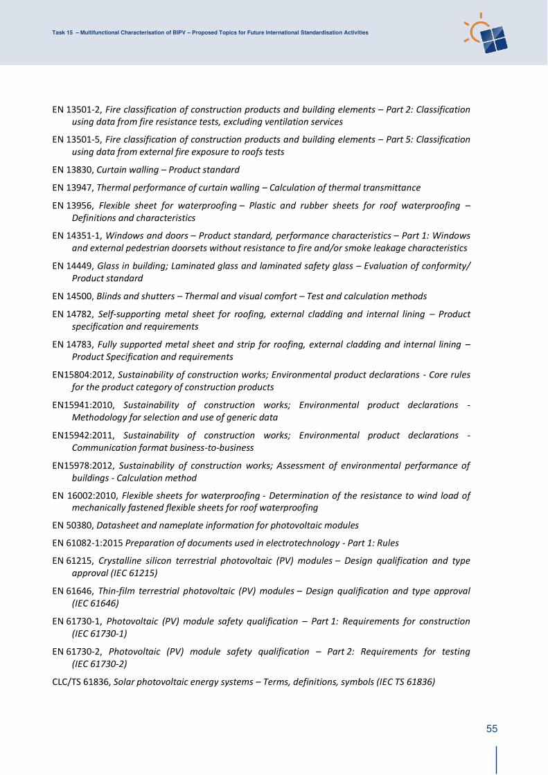
Task 15 – Multifunctional Characterisation of BIPV – Proposed Topics for Future International Standardisation Activities
55
EN 13501-2, Fire classification of construction products and building elements – Part 2: Classification
using data from fire resistance tests, excluding ventilation services
EN 13501-5, Fire classification of construction products and building elements – Part 5: Classification
using data from external fire exposure to roofs tests
EN 13830, Curtain walling – Product standard
EN 13947, Thermal performance of curtain walling – Calculation of thermal transmittance
EN 13956, Flexible sheet for waterproofing – Plastic and rubber sheets for roof waterproofing –
Definitions and characteristics
EN 14351-1, Windows and doors – Product standard, performance characteristics – Part 1: Windows
and external pedestrian doorsets without resistance to fire and/or smoke leakage characteristics
EN 14449, Glass in building; Laminated glass and laminated safety glass – Evaluation of conformity/
Product standard
EN 14500, Blinds and shutters – Thermal and visual comfort – Test and calculation methods
EN 14782, Self-supporting metal sheet for roofing, external cladding and internal lining – Product
specification and requirements
EN 14783, Fully supported metal sheet and strip for roofing, external cladding and internal lining –
Product Specification and requirements
EN15804:2012, Sustainability of construction works; Environmental product declarations - Core rules
for the product category of construction products
EN15941:2010, Sustainability of construction works; Environmental product declarations -
Methodology for selection and use of generic data
EN15942:2011, Sustainability of construction works; Environmental product declarations -
Communication format business-to-business
EN15978:2012, Sustainability of construction works; Assessment of environmental performance of
buildings - Calculation method
EN 16002:2010, Flexible sheets for waterproofing - Determination of the resistance to wind load of
mechanically fastened flexible sheets for roof waterproofing
EN 50380, Datasheet and nameplate information for photovoltaic modules
EN 61082-1:2015 Preparation of documents used in electrotechnology - Part 1: Rules
EN 61215, Crystalline silicon terrestrial photovoltaic (PV) modules – Design qualification and type
approval (IEC 61215)
EN 61646, Thin-film terrestrial photovoltaic (PV) modules – Design qualification and type approval
(IEC 61646)
EN 61730-1, Photovoltaic (PV) module safety qualification – Part 1: Requirements for construction
(IEC 61730-1)
EN 61730-2, Photovoltaic (PV) module safety qualification – Part 2: Requirements for testing
(IEC 61730-2)
CLC/TS 61836, Solar photovoltaic energy systems – Terms, definitions, symbols (IEC TS 61836)

Task 15 – Multifunctional Characterisation of BIPV – Proposed Topics for Future International Standardisation Activities
56
EN 62446, Grid connected photovoltaic systems – Minimum requirements for system documentation,
commissioning tests and inspection (IEC 62446)
EN 82079-1:2012 Preparation of instructions for use - Structuring, content and presentation - Part 1:
General principles and detailed requirements
8.5 Normative references for EN 50583-2
For dated references, only the edition cited applies. For undated references, the latest edition of the
referenced document (including any amendments) applies.
EN 410, Glass in building – Determination of luminous and solar characteristics of glazing
EN 1027:2000, Windows and doors - Watertightness - Test method
EN 1990, Eurocode: Basis of structural design
EN 1991 (all parts), Eurocode 1: Actions on structures
EN 1993 (all parts), Eurocode 3: Design of steel structures
EN 1995 (all parts), Eurocode 5: Design of timber structures
EN 1999 (all parts), Eurocode 9: Design of aluminium structures
EN ISO 6946, Building components and building elements – Thermal resistance and thermal
transmittance – Calculation method (ISO 6946)
EN 12179, Curtain walling – Resistance to wind load – Test method
prEN 12488, Glass in building – Glazing requirements – Assembly rules for vertical glazing
EN 12519, Windows and pedestrian doors – Terminology
EN ISO 12543-1, Glass in building – Laminated glass and laminated safety glass – Part 1: Definitions
and description of component parts (ISO 12543-1)
EN ISO 12543-2, Glass in building – Laminated glass and laminated safety glass – Part 2: Laminated
safety glass (ISO 12543-2)
EN ISO 12543-3, Glass in building – Laminated glass and laminated safety glass – Part 3: Laminated
glass (ISO 12543-3)
EN ISO 12543-4, Glass in building – Laminated glass and laminated safety glass – Part 4: Test methods
for durability (ISO 12543-4)
EN ISO 12543-5, Glass in building – Laminated glass and laminated safety glass – Part 5: Dimensions
and edge finish (ISO 12543-5)
EN ISO 12543-6, Glass in building – Laminated glass and laminated safety glass – Part 6: Appearance
(ISO 12543-6)
EN 12600, Glass in building – Pendulum test – Impact test method and classification for flat glass
EN 12758, Glass in building – Glazing and airborne sound insulation – Product descriptions and
determination of properties
EN 13022 (all parts), Glass in building – Structural sealant glazing
EN 13116, Curtain walling – Resistance to wind load – Performance requirements
EN 13119, Curtain walling – Terminology
Task 15 – Multifunctional Characterisation of BIPV – Proposed Topics for Future International Standardisation Activities
57
EN 13363-1, Solar protection devices combined with glazing – Calculation of solar and light
transmittance – Part 1: Simplified method
EN 13363-2, Solar protection devices combined with glazing – Calculation of total solar energy
transmittance and light transmittance – Part 2: Detailed calculation method
EN 13501-2, Fire classification of construction products and building elements – Part 2: Classification
using data from fire resistance tests, excluding ventilation services
EN 13501-5, Fire classification of construction products and building elements – Part 5: Classification
using data from external fire exposure to roofs tests
EN 13830, Curtain walling – Product standard
EN 13947, Thermal performance of curtain walling – Calculation of thermal transmittance
EN 13956, Flexible sheet for waterproofing – Plastic and rubber sheets for roof waterproofing –
Definitions and characteristics
EN 14351-1, Windows and doors – Product standard, performance characteristics – Part 1: Windows
and external pedestrian doorsets without resistance to fire and/or smoke leakage characteristics
but including external fire performance for roof windows
prEN ISO 14439 3), Glass in building — Glazing requirements — Use of glazing blocks (ISO 14439)
EN 14500, Blinds and shutters – Thermal and visual comfort – Test and calculation methods
EN 14782, Self-supporting metal sheet for roofing, external cladding and internal lining – Product
specification and requirements
EN 14783, Fully supported metal sheet and strip for roofing, external cladding and internal lining –
Product Specification and requirements
CEN/TR 15601:2012, Hygrothermal performance of buildings – Resistance to wind-driven rain of roof
coverings with discontinuously laid small elements – Test method
EN15804:2012, Sustainability of construction works; Environmental product declarations - Core rules
for the product category of construction products
EN15941:2010, Sustainability of construction works; Environmental product declarations -
Methodology for selection and use of generic data
EN15942:2011, Sustainability of construction works; Environmental product declarations -
Communication format business-to-business
EN15978:2012, Sustainability of construction works; Assessment of environmental performance of
buildings - Calculation method
EN 50583 Part 1 - Photovoltaics in buildings – BIPV modules
HD 60364-7-712, Electrical installations of buildings – Part 7-712: Requirements for special
installations or locations - Solar photovoltaic (PV) power supply systems (IEC 60364-7-712)
EN 16002:2010, Flexible sheets for waterproofing - Determination of the resistance to wind load of
mechanically fastened flexible sheets for roof waterproofing
3) Abandoned project.

Task 15 – Multifunctional Characterisation of BIPV – Proposed Topics for Future International Standardisation Activities
58
EN 61082-1:2015 Preparation of documents used in electrotechnology - Part 1: Rules
CLC/TS 61836, Solar photovoltaic energy systems – Terms, definitions, symbols (IEC TS 61836)
EN 62446, Grid connected photovoltaic systems – Minimum requirements for system
documentation, commissioning tests and inspection (IEC 62446)
EN 82079-1:2012 Preparation of instructions for use - Structuring, content and presentation - Part 1:
General principles and detailed requirements
ETAG 002, Guideline for European Technical Approval for Structural Sealant Glazing Systems – SSGS
ETAG 006, Guideline for European Technical Approval of Systems of Mechanically Fastened Flexible
Waterproofing Membranes
N 0068/CEN-TC128-WG3-N0068 TR Renewable energy systems for roof structural connections

Task 15 – Multifunctional Characterisation of BIPV – Proposed Topics for Future International Standardisation Activities
1