Multidimensional and Multiphase Numerical Analysis of...
11
Seminar Nasional Besi dan Baja II ( ), Aula Barat, ITB, 20-21 Oktober 2011 Sesi I.2 - hal. 1 Multidimensional and Multiphase Numerical Analysis of Blast Furnace Ironmaking Operation Sungging Pintowantoro Jurusan Teknik Material dan Metalurgi FTI, Institut Teknologi Sepuluh Nopember (ITS), Kampus ITS Sukolilo, Surabaya 6011, Indonesia [email protected] Abstract The production of pig iron in the blast furnace is the major route among various iron making processes. The improvement in productivity, coke consumption and fuel use within the process has become the major issue in steelworks. For these reason that pulverized coal injection (PCI) has become a standard in most blast furnace operation with injection rates varying from 100 to over 200 kg/thm, in order to decrease coke consumption. With increased in PCI rate into blast furnace, more unburned pulverized coal (UPC) and coke degradation would be generated. The large amount of powder deposited (static powder) would be deteriorate permeability and possible hanging of the burden in the blast furnace. In order to overcome these problems, it is necessary to elucidate the flow characteristics of powder deposited for the achievement of high PCI rate and the stable operation of the blast furnace. Previous blast furnace models have considered up to four phases in the blast furnace (solids, gas, liquids and powders). Recently, although there have been extensive effort to understanding of flow characteristic of powder in blast furnace found in previous literatures, the behavior of powders using separate treatment of dynamic and static powder in blast furnace has yet to be reported. Therefore, they need to be considered as different phases possessing own motions, energy and phase composition. Although various mathematical models of the blast furnace have been reported in previous literatures, most have made many simplifications to the governing equations, and several important blast furnace features like three-dimensional and transient behaviors have been ignored. It is well known that thermo physical properties of powder from unburned PC and coke degradation are quite different each other, such as density, viscosity, specific heat and thermal conductivity. Therefore, they need to be considered as different phases possessing own motions, energy and phase composition. The other influence to control and optimize permeability, especially in the deadman region is the motion of coke particles. In this study, a mathematical model, which does consider the flow characteristic of powders in the blast furnace with eight major phases simultaneously interacting via multiphase chemical kinetics and physical changes, is developed. The model solves rigorous conservation equations for all phases simultaneously; moreover the model was extended to consider eight phases for analyze total powder deposition in blast furnace quantitatively. This model is applied to simulate the actual and several advanced blast furnace operations. KEY WORDS: blast furnace; mathematical modeling; multidimensional; multi-phase flow; pulverized coal injection; chemical reactions; static powders holdup. I. Introduction The blast furnace (BF) represents the predominant ironmaking process in the world. More than 95% hot metal produced from iron ore comes from blast furnaces. It is apparent that the lead role of blast furnaces in hot metal production will remain unchanged well into the future. A blast furnace is capital and energy intensive. [1] To maintain and improve the competitiveness of the blast furnace process, it is necessary to achieve a considerable decrease in coke and total energy consumption for primary metal production along with minimization of environmental impacts. Pulverized coal injection (PCI), which provides
Transcript of Multidimensional and Multiphase Numerical Analysis of...
Seminar Nasional Besi dan Baja II ( ), Aula Barat, ITB, 20-21 Oktober 2011 Sesi I.2 - hal. 1
Multidimensional and Multiphase Numerical Analysis of Blast Furnace Ironmaking Operation
Sungging Pintowantoro Jurusan Teknik Material dan Metalurgi FTI, Institut Teknologi Sepuluh Nopember (ITS),
Kampus ITS Sukolilo, Surabaya 6011, Indonesia [email protected]
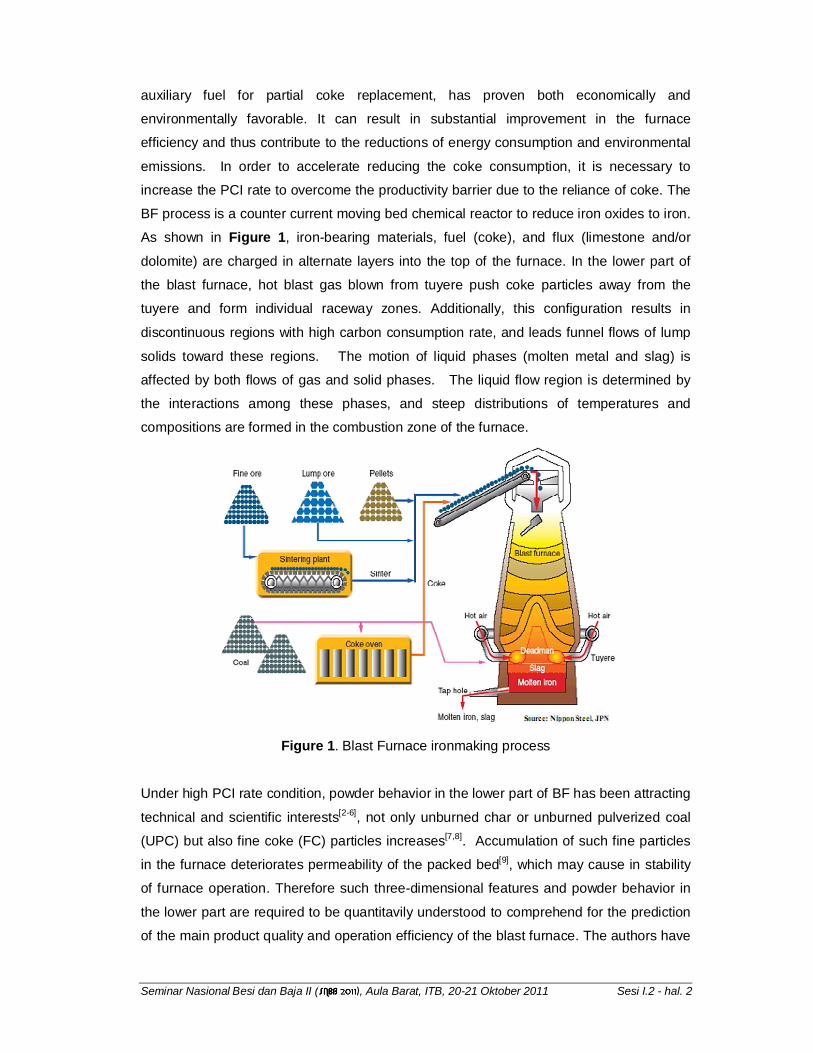
Abstract
The production of pig iron in the blast furnace is the major route among various iron making processes. The improvement in productivity, coke consumption and fuel use within the process has become the major issue in steelworks. For these reason that pulverized coal injection (PCI) has become a standard in most blast furnace operation with injection rates varying from 100 to over 200 kg/thm, in order to decrease coke consumption. With increased in PCI rate into blast furnace, more unburned pulverized coal (UPC) and coke degradation would be generated. The large amount of powder deposited (static powder) would be deteriorate permeability and possible hanging of the burden in the blast furnace. In order to overcome these problems, it is necessary to elucidate the flow characteristics of powder deposited for the achievement of high PCI rate and the stable operation of the blast furnace. Previous blast furnace models have considered up to four phases in the blast furnace (solids, gas, liquids and powders). Recently, although there have been extensive effort to understanding of flow characteristic of powder in blast furnace found in previous literatures, the behavior of powders using separate treatment of dynamic and static powder in blast furnace has yet to be reported. Therefore, they need to be considered as different phases possessing own motions, energy and phase composition. Although various mathematical models of the blast furnace have been reported in previous literatures, most have made many simplifications to the governing equations, and several important blast furnace features like three-dimensional and transient behaviors have been ignored. It is well known that thermo physical properties of powder from unburned PC and coke degradation are quite different each other, such as density, viscosity, specific heat and thermal conductivity. Therefore, they need to be considered as different phases possessing own motions, energy and phase composition. The other influence to control and optimize permeability, especially in the deadman region is the motion of coke particles. In this study, a mathematical model, which does consider the flow characteristic of powders in the blast furnace with eight major phases simultaneously interacting via multiphase chemical kinetics and physical changes, is developed. The model solves rigorous conservation equations for all phases simultaneously; moreover the model was extended to consider eight phases for analyze total powder deposition in blast furnace quantitatively. This model is applied to simulate the actual and several advanced blast furnace operations.
KEY WORDS: blast furnace; mathematical modeling; multidimensional; multi-phase flow; pulverized coal injection; chemical reactions; static powders holdup.
I. Introduction
The blast furnace (BF) represents the predominant ironmaking process in the world. More
than 95% hot metal produced from iron ore comes from blast furnaces. It is apparent that
the lead role of blast furnaces in hot metal production will remain unchanged well into the
future. A blast furnace is capital and energy intensive.[1] To maintain and improve the
competitiveness of the blast furnace process, it is necessary to achieve a considerable
decrease in coke and total energy consumption for primary metal production along with
minimization of environmental impacts. Pulverized coal injection (PCI), which provides
Seminar Nasional Besi dan Baja II ( ), Aula Barat, ITB, 20-21 Oktober 2011 Sesi I.2 - hal. 2
auxiliary fuel for partial coke replacement, has proven both economically and
environmentally favorable. It can result in substantial improvement in the furnace
efficiency and thus contribute to the reductions of energy consumption and environmental
emissions. In order to accelerate reducing the coke consumption, it is necessary to
increase the PCI rate to overcome the productivity barrier due to the reliance of coke. The
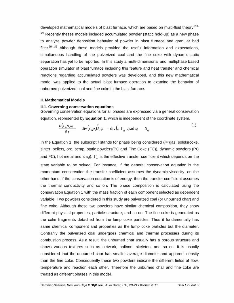
BF process is a counter current moving bed chemical reactor to reduce iron oxides to iron.
As shown in Figure 1, iron-bearing materials, fuel (coke), and flux (limestone and/or
dolomite) are charged in alternate layers into the top of the furnace. In the lower part of
the blast furnace, hot blast gas blown from tuyere push coke particles away from the
tuyere and form individual raceway zones. Additionally, this configuration results in
discontinuous regions with high carbon consumption rate, and leads funnel flows of lump
solids toward these regions. The motion of liquid phases (molten metal and slag) is
affected by both flows of gas and solid phases. The liquid flow region is determined by
the interactions among these phases, and steep distributions of temperatures and
compositions are formed in the combustion zone of the furnace.
Figure 1. Blast Furnace ironmaking process
Under high PCI rate condition, powder behavior in the lower part of BF has been attracting
technical and scientific interests[2-6], not only unburned char or unburned pulverized coal
(UPC) but also fine coke (FC) particles increases[7,8]. Accumulation of such fine particles
in the furnace deteriorates permeability of the packed bed[9], which may cause in stability
of furnace operation. Therefore such three-dimensional features and powder behavior in
the lower part are required to be quantitavily understood to comprehend for the prediction
of the main product quality and operation efficiency of the blast furnace. The authors have
Seminar Nasional Besi dan Baja II ( ), Aula Barat, ITB, 20-21 Oktober 2011 Sesi I.2 - hal. 3
developed mathematical models of blast furnace, which are based on multi-fluid theory.[10-
14] Recently theses models included accumulated powder (static hold-up) as a new phase
to analyze powder deposition behavior of powder in blast furnace and granular bad
filter.[15-17] Although these models provided the useful information and expectations,
simultaneous handling of the pulverized coal and the fine coke with dynamic-static
separation has yet to be reported. In this study a multi-dimensional and multiphase based
operation simulator of blast furnace including this feature and heat transfer and chemical
reactions regarding accumulated powders was developed, and this new mathematical
model was applied to the actual blast furnace operation to examine the behavior of
unburned pulverized coal and fine coke in the blast furnace.
II. Mathematical Models
II.1. Governing conservation equations Governing conservation equations for all phases are expressed via a general conservation
equation, represented by Equation 1, which is independent of the coordinate system.
( ) ( ) ( )ii
SUt
iiiiiiiii
φφ φεφρεφρε
+Γ=+∂
∂graddivdiv
r
(1)
In the Equation 1, the subscript i stands for phase being considered (i= gas, solids(coke,
sinter, pellets, ore, scrap, static powders(PC and Fine Coke (FC)), dynamic powders (PC
and FC), hot metal and slag). φΓ is the effective transfer coefficient which depends on the
state variable to be solved. For instance, if the general conservation equation is the
momentum conservation the transfer coefficient assumes the dynamic viscosity, on the
other hand, if the conservation equation is of energy, then the transfer coefficient assumes
the thermal conductivity and so on. The phase composition is calculated using the
conservation Equation 1 with the mass fraction of each component selected as dependent
variable. Two powders considered in this study are pulverized coal (or unburned char) and
fine coke. Although these two powders have similar chemical composition, they show
different physical properties, particle structure, and so on. The fine coke is generated as
the coke fragments detached from the lump coke particles. Thus it fundamentally has
same chemical component and properties as the lump coke particles but the diameter.
Contrarily the pulverized coal undergoes chemical and thermal processes during its
combustion process. As a result, the unburned char usually has a porous structure and
shows various textures such as network, balloon, skeleton, and so on. It is usually
considered that the unburned char has smaller average diameter and apparent density
than the fine coke. Consequently these two powders indicate the different fields of flow,
temperature and reaction each other. Therefore the unburned char and fine coke are
treated as different phases in this model.
Seminar Nasional Besi dan Baja II ( ), Aula Barat, ITB, 20-21 Oktober 2011 Sesi I.2 - hal. 4
Regarding the static powders, their treatment was changed from the previous work.[15,17]
The static powder is treated as a component of the solid phase in the modified model
while the previous model handles is a phase. The solid phase consist of multiple
components such as coke, lump ore, sinter, pellet and so on. These components have
only material balance equations and share temperature and velocity fields among the solid
components. The phases have momentum and heat balance eqeuations and continuity
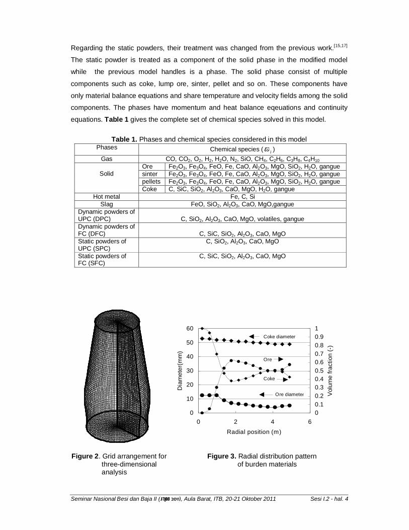
equations. Table 1 gives the complete set of chemical species solved in this model.
Table 1. Phases and chemical species considered in this model
Phases Chemical species ( iω )
Gas CO, CO2, O2, H2, H2O, N2, SiO, CH4, C2H6, C3H8, C4H10 Ore Fe2O3, Fe3O4, FeO, Fe, CaO, Al2O3, MgO, SiO2, H2O, gangue sinter Fe2O3, Fe3O4, FeO, Fe, CaO, Al2O3, MgO, SiO2, H2O, gangue pellets Fe2O3, Fe3O4, FeO, Fe, CaO, Al2O3, MgO, SiO2, H2O, gangue
Solid
Coke C, SiC, SiO2, Al2O3, CaO, MgO, H2O, gangue Hot metal Fe, C, Si
Slag FeO, SiO2, Al2O3, CaO, MgO,gangue Dynamic powders of UPC (DPC)
C, SiO2, Al2O3, CaO, MgO, volatiles, gangue
Dynamic powders of FC (DFC)
C, SiC, SiO2, Al2O3, CaO, MgO
Static powders of UPC (SPC)
C, SiO2, Al2O3, CaO, MgO
Static powders of FC (SFC)
C, SiC, SiO2, Al2O3, CaO, MgO
0
10
20
30
40
50
60
0 2 4 6
Radial position (m)
Dia
me
ter(
mm
)
0
0.1
0.2
0.3
0.4
0.5
0.6
0.7
0.8
0.9
1V
olu
me
fra
ctio
n (
-)Coke diameter
Ore diameter
Ore
Coke
Figure 2. Grid arrangement for three-dimensional analysis
Figure 3. Radial distribution pattern of burden materials
Seminar Nasional Besi dan Baja II ( ), Aula Barat, ITB, 20-21 Oktober 2011 Sesi I.2 - hal. 5
II.2 Boundary conditions
The numerical grid used to simulate the blast furnace process in a three-dimensional
frame is shown in Figure 2. The calculation was carried out in whole the circunferential
direction of the blast furnace, simulating the real shape of the blast furnace. The grid was
constructed by linear distribution of the coordinate lines. The model uses as boundary
conditions the blast composition, flow rate and temperature at the tuyere nose. At the top
of the blast furnace the solid composition, volume fraction and diameter distributions are
specified. At blast furnace wall, a heat loss coefficient is specified based on operational
data of wall heat loss, allowing its variation with the blast furnace wall.
III. Results and discussions
The actual blast furnace operation is simulated. The input data used in this simulation was
taken as the monthly average values. The operational parameters used as input data are
sumarized in Table 2. Figure 3 shows the burden distribution pattern used as boundary
conditions for solid phase at the charging level. Coke was mainly charged at the central
region while ore was charged preferentially in the peripheral region. The mass balance for
all species was lower than 1% and good agreement of the measured and calculated
global parameters like prodution, slag rate and so on is verified in Table 2.
Table 2. Comparison of global parameters Calculated Measured Error (%)
Production (kg/s) 103.5 104.3 0.7 Coke rate (kg/thm) 313.6 313 0.2 Slag rate (kg/thm) 252.8 261 3.1
2
2
COCO
CO
+
53.3 50.6 5.3
Top gas temperature (0C)
248 240 3.3
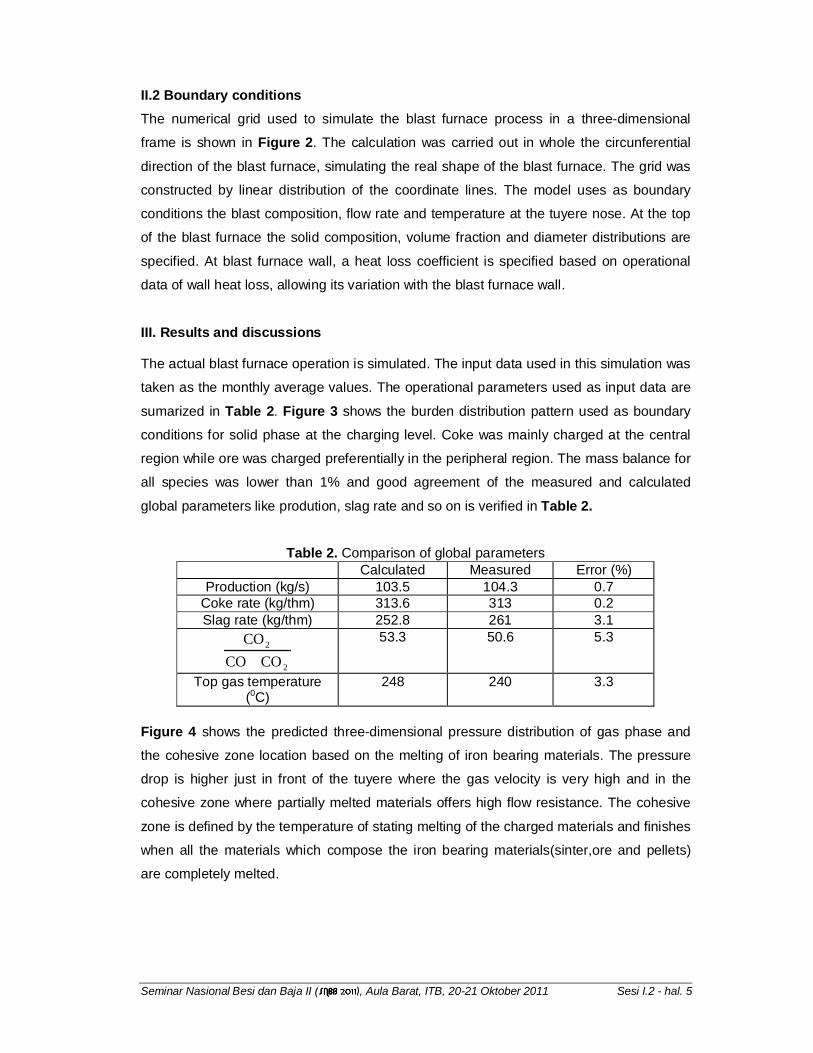
Figure 4 shows the predicted three-dimensional pressure distribution of gas phase and
the cohesive zone location based on the melting of iron bearing materials. The pressure
drop is higher just in front of the tuyere where the gas velocity is very high and in the
cohesive zone where partially melted materials offers high flow resistance. The cohesive
zone is defined by the temperature of stating melting of the charged materials and finishes
when all the materials which compose the iron bearing materials(sinter,ore and pellets)
are completely melted.
Seminar Nasional Besi dan Baja II ( ), Aula Barat, ITB, 20-21 Oktober 2011 Sesi I.2 - hal. 6
3.653.603.473.123.052.922.852.68
Pressure(atm)
a. Gas pressure b. Cohesive zone Figure 4. Three-dimensional pressure drop and cohesive zone location predicted by the
model based on the melting rate
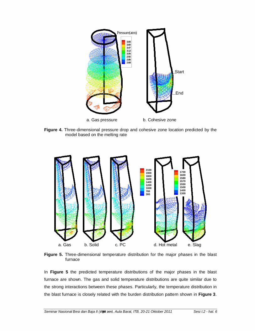
2100190018001600140012001000700300
a. Gas b. Solid c. PC d. Hot metal e. Slag
Figure 5. Three-dimensional temperature distribution for the major phases in the blast furnace
In Figure 5 the predicted temperature distributions of the major phases in the blast
furnace are shown. The gas and solid temperature distributions are quite similar due to
the strong interactions between these phases. Particularly, the temperature distribution in
the blast furnace is closely related with the burden distribution pattern shown in Figure 3.
Start
End
17001600158015701550150014001300
Seminar Nasional Besi dan Baja II ( ), Aula Barat, ITB, 20-21 Oktober 2011 Sesi I.2 - hal. 7
These features of the temperature patterns are due the strong dependence of the gas
flow, chemical reactions and physical properties on the bed porosity. Therefore, as coke
was mainly charged at central region, the main stream of the gas path also is in this region
which in turn, makes the iso-temperature surface higher in this region. The hot metal and
molten slag temperature iso-surface presents also similar pattern with the slag
temperature usualy been higher due to the higher residence time in the dripping zone
compared with hot metal. The temperature of pulverized coal phase is similar to the gas
phase due to the permanent contact of gas and pulverized coal phases through the blast
furnace.
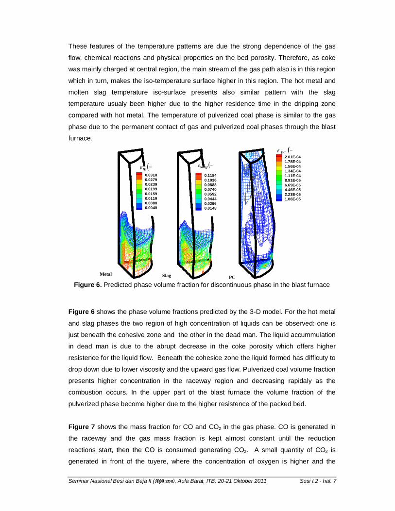
0.03180.02790.02390.01990.01590.01190.00800.0040
0.11840.10360.08880.07400.05920.04440.02960.0148
2.01E-041.78E-041.56E-041.34E-041.11E-048.91E-056.69E-054.46E-052.23E-051.06E-05
Metal Slag PC
( )−mε
( )−pcε
( )−slagε
Figure 6. Predicted phase volume fraction for discontinuous phase in the blast furnace
Figure 6 shows the phase volume fractions predicted by the 3-D model. For the hot metal
and slag phases the two region of high concentration of liquids can be observed: one is
just beneath the cohesive zone and the other in the dead man. The liquid accummulation
in dead man is due to the abrupt decrease in the coke porosity which offers higher
resistence for the liquid flow. Beneath the cohesice zone the liquid formed has difficuty to
drop down due to lower viscosity and the upward gas flow. Pulverized coal volume fraction
presents higher concentration in the raceway region and decreasing rapidaly as the
combustion occurs. In the upper part of the blast furnace the volume fraction of the
pulverized phase become higher due to the higher resistence of the packed bed.
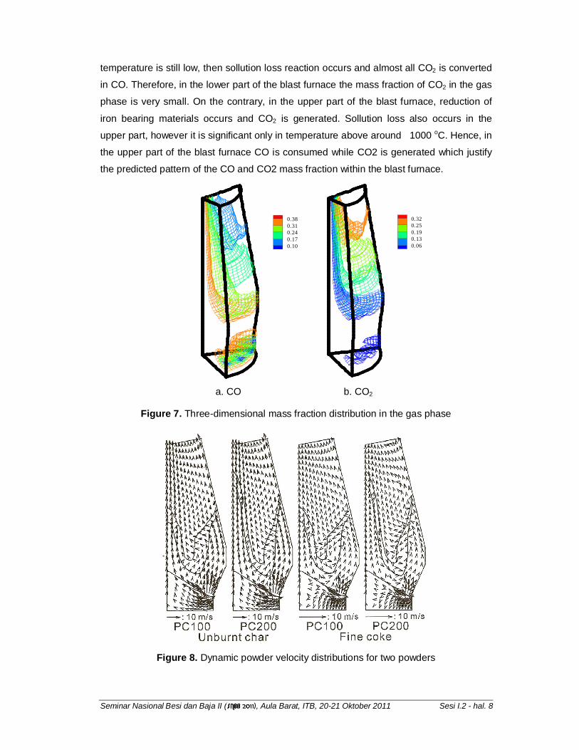
Figure 7 shows the mass fraction for CO and CO2 in the gas phase. CO is generated in
the raceway and the gas mass fraction is kept almost constant until the reduction
reactions start, then the CO is consumed generating CO2. A small quantity of CO2 is
generated in front of the tuyere, where the concentration of oxygen is higher and the
Seminar Nasional Besi dan Baja II ( ), Aula Barat, ITB, 20-21 Oktober 2011 Sesi I.2 - hal. 8
temperature is still low, then sollution loss reaction occurs and almost all CO2 is converted
in CO. Therefore, in the lower part of the blast furnace the mass fraction of CO2 in the gas
phase is very small. On the contrary, in the upper part of the blast furnace, reduction of
iron bearing materials occurs and CO2 is generated. Sollution loss also occurs in the
upper part, however it is significant only in temperature above around 1000 oC. Hence, in
the upper part of the blast furnace CO is consumed while CO2 is generated which justify
the predicted pattern of the CO and CO2 mass fraction within the blast furnace.
0.380.310.240.170.10
0.320.250.190.130.06
a. CO b. CO2
Figure 7. Three-dimensional mass fraction distribution in the gas phase
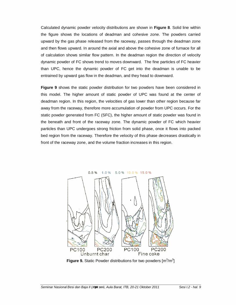
Figure 8. Dynamic powder velocity distributions for two powders
Seminar Nasional Besi dan Baja II ( ), Aula Barat, ITB, 20-21 Oktober 2011 Sesi I.2 - hal. 9
Calculated dynamic powder velocity distributions are shown in Figure 8. Solid line within
the figure shows the locations of deadman and cohesive zone. The powders carried
upward by the gas phase released from the raceway, passes through the deadman zone
and then flows upward. In around the axial and above the cohesive zone of furnace for all
of calculation shows similar flow pattern. In the deadman region the direction of velocity
dynamic powder of FC shows trend to moves downward. The fine particles of FC heavier
than UPC, hence the dynamic powder of FC get into the deadman is unable to be
entrained by upward gas flow in the deadman, and they head to downward.
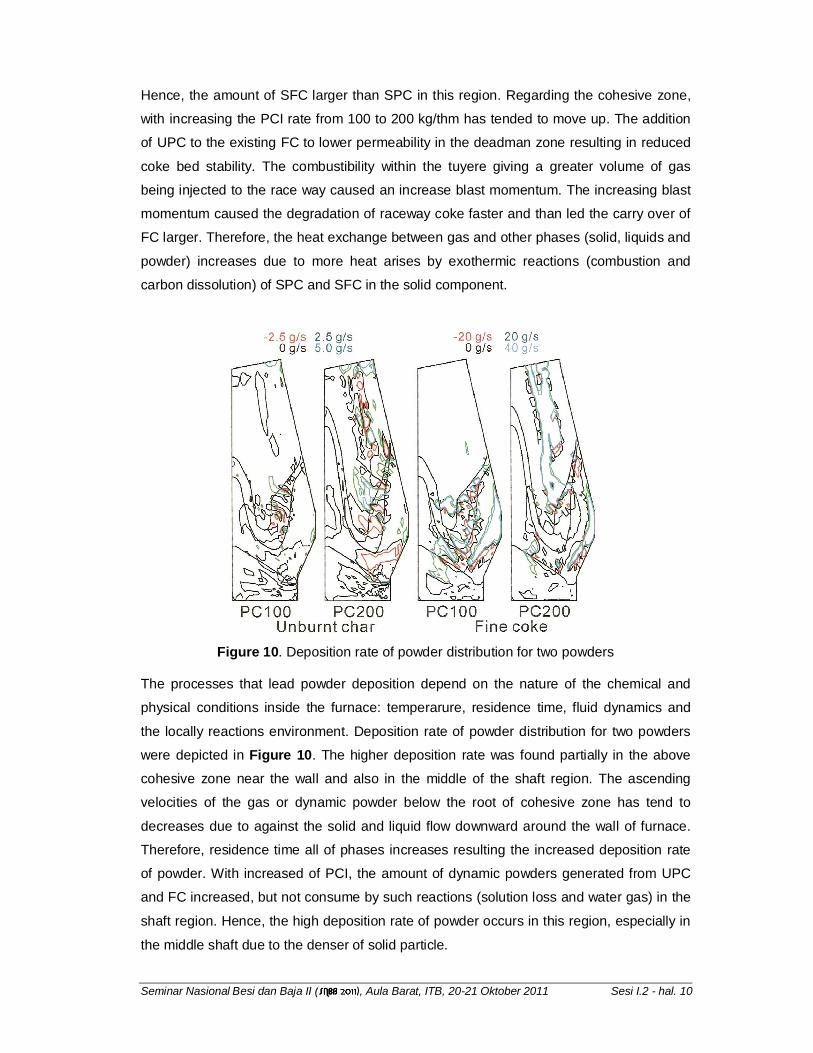
Figure 9 shows the static powder distribution for two powders have been considered in
this model. The higher amount of static powder of UPC was found at the center of
deadman region. In this region, the velocities of gas lower than other region because far
away from the raceway, therefore more accumulation of powder from UPC occurs. For the
static powder generated from FC (SFC), the higher amount of static powder was found in
the beneath and front of the raceway zone. The dynamic powder of FC which heavier
particles than UPC undergoes strong friction from solid phase, once it flows into packed
bed region from the raceway. Therefore the velocity of this phase decreases drastically in
front of the raceway zone, and the volume fraction increases in this region.
Figure 9. Static Powder distributions for two powders [m3/m3]
Seminar Nasional Besi dan Baja II ( ), Aula Barat, ITB, 20-21 Oktober 2011 Sesi I.2 - hal. 10
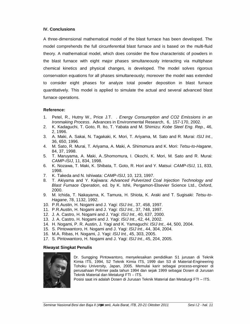
Hence, the amount of SFC larger than SPC in this region. Regarding the cohesive zone,
with increasing the PCI rate from 100 to 200 kg/thm has tended to move up. The addition
of UPC to the existing FC to lower permeability in the deadman zone resulting in reduced
coke bed stability. The combustibility within the tuyere giving a greater volume of gas
being injected to the race way caused an increase blast momentum. The increasing blast
momentum caused the degradation of raceway coke faster and than led the carry over of
FC larger. Therefore, the heat exchange between gas and other phases (solid, liquids and
powder) increases due to more heat arises by exothermic reactions (combustion and
carbon dissolution) of SPC and SFC in the solid component.
Figure 10. Deposition rate of powder distribution for two powders
The processes that lead powder deposition depend on the nature of the chemical and
physical conditions inside the furnace: temperarure, residence time, fluid dynamics and
the locally reactions environment. Deposition rate of powder distribution for two powders
were depicted in Figure 10. The higher deposition rate was found partially in the above
cohesive zone near the wall and also in the middle of the shaft region. The ascending
velocities of the gas or dynamic powder below the root of cohesive zone has tend to
decreases due to against the solid and liquid flow downward around the wall of furnace.
Therefore, residence time all of phases increases resulting the increased deposition rate
of powder. With increased of PCI, the amount of dynamic powders generated from UPC
and FC increased, but not consume by such reactions (solution loss and water gas) in the
shaft region. Hence, the high deposition rate of powder occurs in this region, especially in
the middle shaft due to the denser of solid particle.
Seminar Nasional Besi dan Baja II ( ), Aula Barat, ITB, 20-21 Oktober 2011 Sesi I.2 - hal. 11
IV. Conclusions
A three-dimensional mathematical model of the blast furnace has been developed. The
model comprehends the full circunferential blast furnace and is based on the multi-fluid
theory. A mathematical model, which does consider the flow characteristic of powders in
the blast furnace with eight major phases simultaneously interacting via multiphase
chemical kinetics and physical changes, is developed. The model solves rigorous
conservation equations for all phases simultaneously; moreover the model was extended
to consider eight phases for analyze total powder deposition in blast furnace
quantitatively. This model is applied to simulate the actual and several advanced blast
furnace operations.
Reference:
1. Petel, R., Hutny W., Price J.T. . Energy Consumption and CO2 Emissions in an Ironmaking Process. Advances in Environmental Research, 6, 157-170, 2002.
2. K. Kadaguchi, T. Goto, R. Ito, T. Yabata and M. Shimizu: Kobe Steel Eng. Rep., 46, 2, 1996.
3. A. Maki, A. Sakai, N. Tagakaki, K. Mori, T. Ariyama, M. Sato and R. Murai: ISIJ Int., 36, 650, 1996.
4. M. Sato, R. Murai, T. Ariyama, A. Maki, A. Shimomura and K. Mori: Tetsu-to-Hagane, 84, 37, 1998.
5. T. Maruyama, A. Maki, A..Shomomura, I. Okochi, K. Mori, M. Sato and R. Murai: CAMP-ISIJ, 11, 834, 1998.
6. K. Nozawa, T. Maki, K. Shibata, T. Goto, R. Hori and Y. Matsui: CAMP-ISIJ, 11, 833, 1998.
7. K. Takeda and N. Ishiwata: CAMP-ISIJ, 10, 123, 1997. 8. T. Akiyama and Y. Kajiwara: Advanced Pulverized Coal Injection Technology and
Blast Furnace Operation, ed. by K. Ishii, Pergamon-Elsevier Science Ltd., Oxford, 2000.
9. M. Ichida, T. Nakayama, K. Tamura, H. Shiota, K. Araki and T. Sugisaki: Tetsu-to-Hagane, 78, 1132, 1992.
10. P.R.Austin, H. Nogami and J. Yagi: ISIJ Int., 37, 458, 1997. 11. P.R.Austin, H. Nogami and J. Yagi: ISIJ Int., 37, 748, 1997. 12. J. A. Castro, H. Nogami and J. Yagi: ISIJ Int., 40, 637, 2000. 13. J. A. Castro, H. Nogami and J. Yagi: ISIJ Int., 42, 44, 2002. 14. H. Nogami, P. R. Austin, J. Yagi and K. Yamaguchi: ISIJ Int., 44, 500, 2004. 15. S. Pintowantoro, H. Nogami and J. Yagi: ISIJ Int., 44, 304, 2004. 16. M.A. Ribas, H. Nogami, J. Yagi: ISIJ Int., 45, 303, 2005. 17. S. Pintowantoro, H. Nogami and J. Yagi: ISIJ Int., 45, 204, 2005.
Riwayat Singkat Penulis
Dr. Sungging Pintowantoro, menyelesaikan pendidikan S1 jurusan di Teknik Kimia ITS, 1994, S2 Teknik Kimia ITS, 1999 dan S3 di Material-Engineering Tohoku University, Japan, 2005. Memulai karir sebagai process-engineer di perusahaan Polimer pada tahun 1994 dan sejak 1999 sebagai Dosen di Jurusan Teknik Material dan Metalurgi FTI – ITS. Posisi saat ini adalah Dosen di Jurusan Teknik Material dan Metalurgi FTI – ITS.