Multichannel, multifunction Transmitter/Controller · · 2016-12-218619 multiCELL p. 1/13 Type...
13
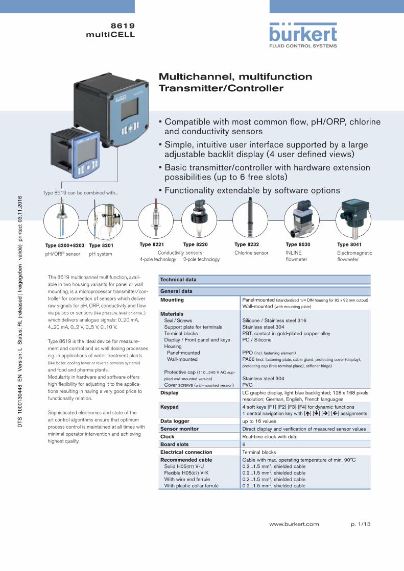
8619 multiCELL p. 1/13 www.burkert.com Type 8221 4-pole technology Type 8220 2-pole technology Multichannel, multifunction Transmitter/Controller The 8619 multichannel multifunction, avail- able in two housing variants for panel or wall mounting, is a microprocessor transmitter/con- troller for connection of sensors which deliver raw signals for pH, ORP, conductivity and flow via pulses or sensors (like pressure, level, chlorine...) which delivers analogue signals: 0...20 mA, 4...20 mA, 0...2 V, 0...5 V, 0...10 V. Type 8619 is the ideal device for measure- ment and control and as well dosing processes e.g. in applications of water treatment plants (like boiler, cooling tower or reverse osmosis systems) and food and pharma plants. Modularity in hardware and software offers high flexibility for adjusting it to the applica- tions resulting in having a very good price to functionality relation. Sophisticated electronics and state of the art control algorithms ensure that optimum process control is maintained at all times with minimal operator intervention and achieving highest quality. Technical data General data Mounting Panel-mounted (standardized 1/4 DIN housing for 92 x 92 mm cutout) Wall-mounted (with mounting plate) Materials Seal / Screws Support plate for terminals Terminal blocks Display / Front panel and keys Housing Panel-mounted Wall-mounted Protective cap (110...240 V AC sup- plied wall-mounted version) Cover screws (wall-mounted version) Silicone / Stainless steel 316 Stainless steel 304 PBT, contact in gold-plated copper alloy PC / Silicone PPO (incl. fastening element) PA66 (incl. fastening plate, cable gland, protecting cover (display), protecting cap (free terminal place), stiffener hinge) Stainless steel 304 PVC Display LC graphic display, light blue backlighted; 128 x 168 pixels resolution; German, English, French languages Keypad 4 soft keys [F1] [F2] [F3] [F4] for dynamic functions 1 central navigation key with [] [] [] [] assignments Data logger up to 16 values Sensor monitor Direct display and verification of measured sensor values Clock Real-time clock with date Board slots 6 Electrical connection Terminal blocks Recommended cable Solid H05(07) V-U Flexible H05(07) V-K With wire end ferrule With plastic collar ferrule Cable with max. operating temperature of min. 90°C 0.2...1.5 mm 2 , shielded cable 0.2...1.5 mm 2 , shielded cable 0.2...1.5 mm 2 , shielded cable 0.2...1.5 mm 2 , shielded cable Type 8200+8203 pH/ORP sensor Type 8201 pH system • Compatible with most common flow, pH/ORP, chlorine and conductivity sensors • Simple, intuitive user interface supported by a large adjustable backlit display (4 user defined views) • Basic transmitter/controller with hardware extension possibilities (up to 6 free slots) • Functionality extendable by software options Type 8619 can be combined with... Type 8232 Chlorine sensor Conductivity sensors Type 8030 INLINE flowmeter Type 8041 Electromagnetic flowmeter
Transcript of Multichannel, multifunction Transmitter/Controller · · 2016-12-218619 multiCELL p. 1/13 Type...
8619multiCELL
p. 1/13www.burkert.com
Type 8221
4-pole technology
Type 8220
2-pole technology
Multichannel, multifunctionTransmitter/Controller
The 8619 multichannel multifunction, avail-
able in two housing variants for panel or wall
mounting, is a microprocessor transmitter/con-
troller for connection of sensors which deliver
raw signals for pH, ORP, conductivity and flow
via pulses or sensors (like pressure, level, chlorine...)
which delivers analogue signals: 0...20 mA,
4...20 mA, 0...2 V, 0...5 V, 0...10 V.
Type 8619 is the ideal device for measure-
ment and control and as well dosing processes
e.g. in applications of water treatment plants
(like boiler, cooling tower or reverse osmosis systems)
and food and pharma plants.
Modularity in hardware and software offers
high flexibility for adjusting it to the applica-
tions resulting in having a very good price to
functionality relation.
Sophisticated electronics and state of the
art control algorithms ensure that optimum
process control is maintained at all times with
minimal operator intervention and achieving
highest quality.
Technical data
General data
Mounting Panel-mounted (standardized 1/4 DIN housing for 92 x 92 mm cutout)
Wall-mounted (with mounting plate)
Materials
Seal / ScrewsSupport plate for terminalsTerminal blocksDisplay / Front panel and keysHousing Panel-mounted
Wall-mounted
Protective cap (110...240 V AC sup-
plied wall-mounted version)
Cover screws (wall-mounted version)
Silicone / Stainless steel 316Stainless steel 304PBT, contact in gold-plated copper alloyPC / Silicone
PPO (incl. fastening element) PA66 (incl. fastening plate, cable gland, protecting cover (display),
protecting cap (free terminal place), stiffener hinge)
Stainless steel 304PVC
Display LC graphic display, light blue backlighted; 128 x 168 pixels resolution; German, English, French languages
Keypad 4 soft keys [F1] [F2] [F3] [F4] for dynamic functions 1 central navigation key with [] [] [] [] assignments
Data logger up to 16 values
Sensor monitor Direct display and verification of measured sensor values
Clock Real-time clock with date
Board slots 6
Electrical connection Terminal blocks
Recommended cable
Solid H05(07) V-UFlexible H05(07) V-KWith wire end ferruleWith plastic collar ferrule
Cable with max. operating temperature of min. 90°C0.2...1.5 mm2, shielded cable0.2...1.5 mm2, shielded cable0.2...1.5 mm2, shielded cable0.2...1.5 mm2, shielded cable
Type 8200+8203
pH/ORP sensor
Type 8201
pH system
• Compatible with most common flow, pH/ORP, chlorine and conductivity sensors
• Simple, intuitive user interface supported by a large adjustable backlit display (4 user defined views)
• Basic transmitter/controller with hardware extension possibilities (up to 6 free slots)
• Functionality extendable by software optionsType 8619 can be combined with...
Type 8232
Chlorine sensorConductivity sensors
Type 8030
INLINE
flowmeter
Type 8041
Electromagnetic
flowmeter

8619multiCELL
p. 2/13
Electrical data
Device version Panel-mounted - Mainboard Wall-mounted - Power supply board
Operating voltage
(“SUPPLY”)
12...30 V DC, ±10%, max. 2 A, filtered and regulated, SELV (safety extra low voltage) circuit with a non dangerous energy level
• 12...36 V DC ±10%, max. 2 A, filtered and regulated, SELV (safety extra low voltage) circuit with a non dangerous energy level
• 110...240 V AC, 50...60 Hz, max. 500 mA, integrated protection: 3.15 A time delay fuseground cable cross-section: 1.5 mm2
Power consumption
(of multiCELL device - without
additional boards and outputs
not connected)
Max. 1.5 VA Max. 2 VA
Power charges
(“PWR OUT” or “POWER
OUT” acc. to version)
12...30 V DC, max 1.8 Aprotected against polarity reversals
• 12...36 V DC version: 12...36 V DC, max 1.8 A; protected against polarity reversals
• 110...240 V AC version:24 V DC±2%, filtered and regulated, SELV (safety extra low
voltage) circuit with a non dangerous energy level, max 1.2 Aprotected against polarity reversalsThe allowed max. current depends on the ambient tem-perature: see diagram below
Device version Panel-mounted - Mainboard Wall-mounted - Mainboard
Digital inputs
DI1, DI2
Voltage: 0...36 V DC, input impedance 3 kSwitching threshold : Von = 5...36 V DC, Voff < 2 V DC; Frequency: 0.5...2500 HzGalvanic insulation, protected against reversed polarity of DC and voltage spikes
Voltage: 0...36 V DC, input impedance 3 kSwitching threshold : Von = 5...36 V DC, Voff < 2 V DC; Frequency: 0.5...2500 HzGalvanic insulation, protected against reversed polarity of DC and voltage spikes
Digital outputs
DO1, DO2
Transistor: can be wired as PNP or NPN, galvanic insula-tion, protected against short circuit, max. 36 V DC, max. 700 mA per transistor output, 1 A max. in total if both tran-sistor outputs are used; Operating modes: On/Off, Hysteresis, Window, PWM, PFM, Pulse; Frequency: max. 2000 Hz
Transistor: can be wired as PNP or NPN, galvanic insula-tion, protected against short circuit, max. 36 V DC, max. 700 mA per transistor output, 1 A max. in total if both tran-sistor outputs are used; Operating modes: On/Off, Hysteresis, Window, PWM, PFM, Pulse; Frequency: max. 2000 Hz
Analogue output
AO1, AO2
4...20 mA, can be wired as sourcing or sinking, galvanic insulation, protected against reversed polarity of DC,max. loop impedance:860 at 30 V DC, 610 at 24 V DC,100 at 12 V DC Resolution: 6 µA
4...20 mA, can be wired as sourcing or sinking, galvanic insulation, protected against reversed polarity of DC,max. loop impedance:1100 at 36 V DC, 610 at 24 V DC,100 at 12 V DCResolution: 6 µA
Memory card
Type / Capacity SD (Secure Digital) or SDHC (Secure Digital High Capacity) / max. 8 GBNote: We recommend to use the 8 GB SDHC memory card available at Bürkert (see accessories on page 12) because it has been
tested with and validated for the 8619 Transmitter/Controller. Another memory card may not operate correctly.
If the device is mounted in a humid environment or outside the maximum allowed voltages are 35 V DC instead of 36 V DC.
Max. allowed current in dependence of the ambient temperature (for wall-mounted version, 110...240 V AC)
For UL certified device
[A]
[°C]
-10 +100 +20 +30 +40 +50 +60 +70 +800
0.8
1.2
1.8
Ambient temperature
Max. current
Wall-mounted version, 110...240 V AC, without extension board
Wall-mounted version, 110...240 V AC, with extension boards
[A]
[°C]
-10 +100 +20 +30 +40 +50 +60 +70 +800
0.8
1.2
1.8
0.2
Ambient temperature
Wall-mounted version, 110...240 V AC, without extension board
Wall-mounted version, 110...240 V AC, with extension boards
Max. current
8619multiCELL
p. 3/13
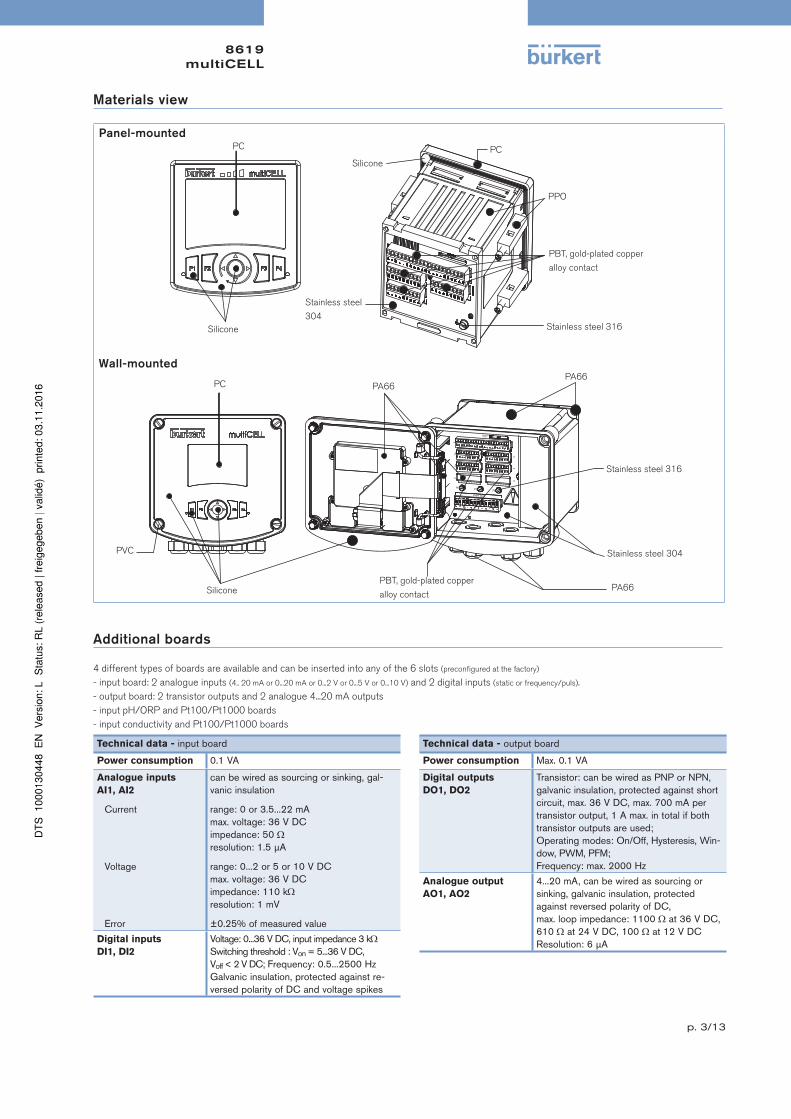
Materials view
Panel-mounted
PBT, gold-plated copper
alloy contact
PPO
PC
Stainless steel 316Silicone
PC
Stainless steel
304
Silicone
Wall-mounted
PEPEPE
M0
M1
M2
M3M4
M5
M6
PWR OUT
MEMORYCARD
1 2 3 4 5 6 7 8 9 1 2 3 4 5 6 7 8 9
PVC
PA66
PA66
PA66
Silicone
PC
Stainless steel 316
Stainless steel 304
PBT, gold-plated copper
alloy contact
Additional boards
4 different types of boards are available and can be inserted into any of the 6 slots (preconfigured at the factory)
- input board: 2 analogue inputs (4.. 20 mA or 0...20 mA or 0...2 V or 0...5 V or 0...10 V) and 2 digital inputs (static or frequency/puls).
- output board: 2 transistor outputs and 2 analogue 4...20 mA outputs
- input pH/ORP and Pt100/Pt1000 boards
- input conductivity and Pt100/Pt1000 boards
Technical data - input board
Power consumption 0.1 VA
Analogue inputs
AI1, AI2
Current
Voltage
Error
can be wired as sourcing or sinking, gal-vanic insulation
range: 0 or 3.5...22 mAmax. voltage: 36 V DCimpedance: 50 resolution: 1.5 µA
range: 0...2 or 5 or 10 V DCmax. voltage: 36 V DCimpedance: 110 k resolution: 1 mV
±0.25% of measured value
Digital inputs
DI1, DI2
Voltage: 0...36 V DC, input impedance 3 kSwitching threshold : Von = 5...36 V DC, Voff < 2 V DC; Frequency: 0.5...2500 HzGalvanic insulation, protected against re-versed polarity of DC and voltage spikes
Technical data - output board
Power consumption Max. 0.1 VA
Digital outputs
DO1, DO2
Transistor: can be wired as PNP or NPN, galvanic insulation, protected against short circuit, max. 36 V DC, max. 700 mA per transistor output, 1 A max. in total if both transistor outputs are used;Operating modes: On/Off, Hysteresis, Win-dow, PWM, PFM;Frequency: max. 2000 Hz
Analogue output
AO1, AO2
4...20 mA, can be wired as sourcing or sinking, galvanic insulation, protected against reversed polarity of DC,max. loop impedance: 1100 at 36 V DC, 610 at 24 V DC, 100 at 12 V DCResolution: 6 µA

8619multiCELL
p. 4/13
Technical data - pH/ORP board
Power consumption 0.1 VA
pH/ORP input simultaneous pH and ORP measurement with input for electrochemical pH/ORP
Temperature input Pt100/Pt1000, 2 or 3 wires
pH measurement
Measuring rangeResolutionMeasurement deviationProbe type
-2.0...16 pH or -600...+600 mV0.01 pH or 0.1 mV±0.02 pH or 1 mV + error of the pH probe*electrochemical
ORP measurement
Measuring rangeResolutionMeasurement deviationProbe type
-2000...+2000 mV0.1 mV±1 mV + error of the ORP probe*electrochemical
Temperature
measurement
Measuring rangeResolutionMeasurement deviationProbe type
-25...+130°C (-20...+266°F)
0.1°C (0.18°F)
±1°C (1.8°F) + error of the temperature probe*Pt100/Pt1000, 2 or 3 wires
* see related probe data sheet
Technical data - conductivity board
Power consumption 0.25 VA
Conductivity input Operation with 2- or 4-pole-technology sensors
Temperature input Pt100/Pt1000, 2 or 3 wires
Conductivity/Resistivity
measurement
Conductivity Measuring rangeResolutionMeasurement deviation
Resistivity Measuring range
ResolutionMeasurement deviation
0 µS/cm...2 S/cm (function of the conductivity cell)
1 nS/cm±0.5% of measured value + error of the conductivity probe*
0.5 .cm...100 M.cm (function of the conductivity cell);
5.0 ...1 M (conductivity board alone)
0.1 .cm±0.5% of measured value + error of the conductivity probe*
Temperature
measurement
Measuring rangeResolutionMeasurement deviationProbe type
-40...+200°C (-40...+392°F)
0.1°C (0.18°F)
±1°C (1.8°F) + error of the temperature probe*Pt100/Pt1000, 2 or 3 wires
* see related probe data sheet
Environment conditions and standards - Mainboard, pH/ORP, conductivity, input and output boards
Ambient temperature
Operation (with/without
memory card1))
Only Mainboard
Min. 1 additionnal board
Storage
• Panel-mounted and 110...240 V AC wall-mounted version: -10...+70°C (14...+158°F)
• 12...36 V DC wall-mounted version: -10...+75°C (14...+167°F)
• all versions:-10...+60°C (14...+140°F)
• all versions:-20...+70°C (-4...+140°F),
limited to -10...+70°C (14...+140°F) if memory card is inserted
Relative humidity < 85%, without condensation
Height above sea level max. 2000 m1) if a different memory card is used, observe the operating temperatures specified by its manufacturer
Protection class
Panel-mounted version
Wall-mounted version
acc. to EN60529IP65 (panel-mounted, cabinet closed)
IP20 (panel-mounted, inside the cabinet)
NEMA250 4X (panel-mounted, in front of the closed
cabinet)
IP65, IP67, if the following conditions are met:- glands body tightened with a tightening
torque of 5.5 Nm±20%, made at factory- glands blanked off or wired- gland nuts tightened with a tightening
torque of 4.5 Nm±20%- housing closed- 4 screws of cover cross tightened with
a tightening torque of 1.4 Nm±20%
Standard and
directives
Certification
UL-Listed for US and Canada
The applied standards, which verify con-formity with the EU Directives, can be found on the EU Type Examination Certificate and/or the EU Declaration of conformity (if ap-
plicable)
61010-1 + CAN/CSA-C22.2 No.61010-1
If the device is mounted in a humid environment or outside the maximum allowed voltages are 35 V DC instead of 36 V DC.

8619multiCELL
p. 5/13
Dimensions [mm]
Panel-mounted
112
10111 102
(112)
(55)
107
max. 4 mm (thickness wall)
Cut-off panel
510
5,55,5
92 +0,5/-0
92 +
0,5/
-0

8619multiCELL
p. 6/13
Dimensions [mm]
Wall-mounted
181
20
185
172
10
Dimensions for drilling
135
90 143
163
155
6.5
The housing variant for wall mounting can also be installed on a pipe using a mounting set (has to be ordered separately, see accessories on page 12).
Principle of operation
The transmitter/controller is given by the internal board based structure capable to handle different types of sensors and selectively execute operations
on the measurement values. From simple measurement and standard signal output and assignment of integrated mathematical formulas for selectable
values up to control and dosing tasks all that can run in parallel.
The boards for signals and functions can be easily connected to each other by configuration and with setting individual parameters all the functionality
can be adapted to the actual process conditions.
The base unit is either a panel-mounted version or a wall-mounted version and handles analogue and digital signal outputs, digital inputs and the front
is supplied by a backlit graphical display. Up to six slots are available, which depending on the applications, can be occupied with boards for pH/ORP,
conductivity, a board with additional analogue and digital outputs as well as a board with analogue and additional digital inputs. There is no need for a
separate 4...20 mA transmitter: the pH, conductivity boards accept raw signals from sensors.
Though highly functional the multiCELL can be operated easily and intuitively. The base for this is the large graphical display and the dynamically as-
signed function keys. Clearly arranged menu and board structures allow easy configuration and setting of parameters and offer a high transparency for
the functions in use. Four user views can be configured by the operator. This allows the user to design a view himself displaying a value arrangement
which he likes to see simultaneously and this can be available 4 times and independent from each other.
For data collection and storage e.g. of measurement values there is an optional data logger available which uses the memory card if inserted in the card
slot. Uploading and restoring the complete database including the application special parameter settings of the complete 8619 and updating firmware
via the memory card is available as standard.

8619multiCELL
p. 7/13
Construction
Memory card slot :
• For upload and download of parameter settings
• Software updates and functional upgrades
Simple operation: insert the memory card into the
small slot on the rear of the device.
The mainboard slot enables:
• connection to the transmitter/controller power
supply
• to power another device
• to dispose of 2 digital inputs (DI),
2 analogue (AO) and 2 digital (DO) outputsAdditional board slots (up to 6) to choose among:
• board for conductivity sensor and/or temperature sensor
(green connector)
• board for pH/ORP sensor and/or temperature sensor (light
grey connector)
• board for 2 analogue and 2 digital outputs
(black connector)
• board for 2 analogue and 2 digital inputs
(small orange connector)
FE
12-36 VDC
FE
Memory card slot :
• For upload and download of parameter settings
• Software updates and functional upgrades
Simple operation: insert the memory card into the
small slot on the rear of the device.
The mainboard slot enables:
• to dispose of 2 digital inputs (DI),
2 analogue (AO) and 2 digital (DO) outputs
Additional board slots (up to 6) to choose among:
• board for conductivity sensor and/or temperature sensor
(green connector)
• board for pH/ORP sensor and/or temperature sensor (light
grey connector)
• board for 2 analogue and 2 digital outputs
(black connector)
• board for 2 analogue and 2 digital inputs
(small orange connector)
The power charges slot enables:
• to power another deviceThe power supply slot enables:
• connection to the transmitter/controller power
supply (behind the protecting cover for 110...240 V AC
version)
Display and dynamic soft keys
F1 F2 F3 F4
The navigation keys allows to move the cursor in vertical and horizontal directionsThe pointer above the navigation key indicates the directions which are usable related to the current display
To activate the dynamic function on the very right side, press F4
To activate the first dynamic function on the very left side, press F1
To activate the third dynamic function, press F3
LED LED
Light blue backlighted LC graphic display
To activate the second dynamic function, press F2
MENU BACK SAVE OK
8619multiCELL
p. 8/13
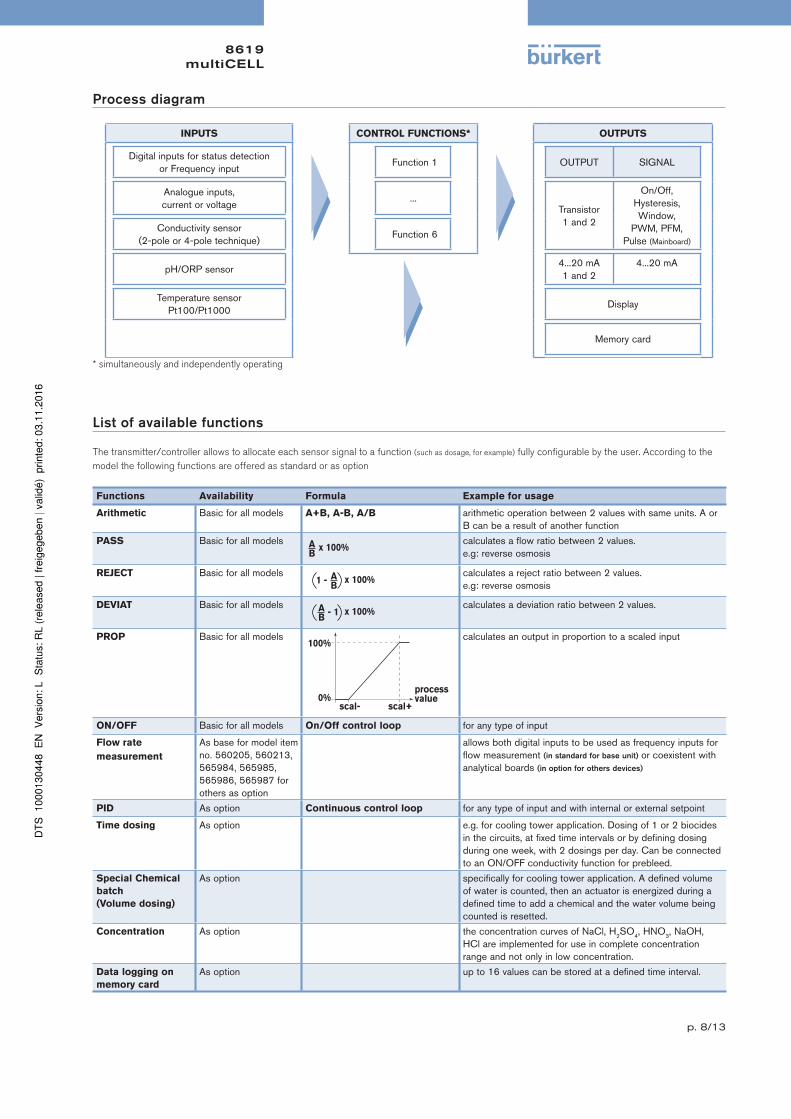
Process diagram
INPUTS CONTROL FUNCTIONS* OUTPUTS
Digital inputs for status detectionor Frequency input
Function 1 OUTPUT SIGNAL
Analogue inputs,current or voltage
...Transistor1 and 2
On/Off,Hysteresis,Window,
PWM, PFM, Pulse (Mainboard)
Conductivity sensor(2-pole or 4-pole technique)
Function 6
pH/ORP sensor4...20 mA1 and 2
4...20 mA
Temperature sensor Pt100/Pt1000
Display
Memory card
* simultaneously and independently operating
List of available functions
The transmitter/controller allows to allocate each sensor signal to a function (such as dosage, for example) fully configurable by the user. According to the
model the following functions are offered as standard or as option
Functions Availability Formula Example for usage
Arithmetic Basic for all models A+B, A-B, A/B arithmetic operation between 2 values with same units. A or B can be a result of another function
PASS Basic for all models calculates a flow ratio between 2 values. e.g: reverse osmosis
REJECT Basic for all models calculates a reject ratio between 2 values. e.g: reverse osmosis
DEVIAT Basic for all models calculates a deviation ratio between 2 values.
PROP Basic for all models calculates an output in proportion to a scaled input
ON/OFF Basic for all models On/Off control loop for any type of input
Flow rate
measurement
As base for model item no. 560205, 560213, 565984, 565985, 565986, 565987 for others as option
allows both digital inputs to be used as frequency inputs for flow measurement (in standard for base unit) or coexistent with analytical boards (in option for others devices)
PID As option Continuous control loop for any type of input and with internal or external setpoint
Time dosing As option e.g. for cooling tower application. Dosing of 1 or 2 biocides in the circuits, at fixed time intervals or by defining dosing during one week, with 2 dosings per day. Can be connected to an ON/OFF conductivity function for prebleed.
Special Chemical
batch
(Volume dosing)
As option specifically for cooling tower application. A defined volume of water is counted, then an actuator is energized during a defined time to add a chemical and the water volume being counted is resetted.
Concentration As option the concentration curves of NaCl, H2SO4, HNO3, NaOH, HCl are implemented for use in complete concentration range and not only in low concentration.
Data logging on
memory card
As option up to 16 values can be stored at a defined time interval.

8619multiCELL
p. 9/13
List of available functions (continued)
Concentration tables multiCELL
If multiCELL 8619 is equipped with an conductivity board, multiCELL is able to calculate the concentration depending on the measured conductivity
and temperature. Therefore concentration tables for binary mixtures of (five) different substances and water are available. This one of the nine concen-
tration ranges has to be selected which fits perfect to the application.
5 10 15 20 25 30 35 40 45 50 55 60 65 70 75 80 85 90 95 100 %
Table salt solution
(NaCl and water)0...26%
Sodium Hydroxide
(NaOH and water)0...14% 18...50%
Hydrochloric acid
(HCl and water)0...18% 22...39%
Nitric acid
(HNO3 and water)0...30% 35...96%
Sulfuric acid
(H2SO4 and water)0...30% 32...84% 92...99%

8619multiCELL
p. 10/13
Menu structure
12010/01/01 00:00
1
0
0
F6:ONOFF
250.0 μS/cmPV
500.0μS/cmSP
0.00 %CMD1
Off F3 Dos.StSPMENU
MENU
2010/01/01 00:00 M6:Outputs
mAAO15.000
12.00
OFF DO2
mAAO2
OFF DO1
First level of Reading mode
(up to 7 different display) :
DISPLAY «M0:» to «M6:»
displays the data of boards 0 to 6
DISPLAY «MAIN» :
displays the base unit main data
Second level of Reading mode
(up to 4 screens for free user data selection for 1, 2 or 4 data display. Only configured views will be displayed)
Third level of Reading mode
displays the data linked to the selected functions (up to 6, only activated func-tion views will be displayed)
MENU
2010/01/01 00:00 M2:Conductivity
25
25.2
mS/cm
°C
MENU
2010/01/01 00:00
39.20
M1:pH
6.53
25.2
pH
mV
°C
MENU
2010/01/01 00:00 M0:MAIN:
L/sDI21.000
33.00
30.00
LDI2
0.500L/sDI1LDI1
MENU
2010/01/01 00:00 M0:MAIN:
mAAO16.000
20.00
OFF DO2
mAAO2
OFF DO1
OFF DI2
OFF DI1
12010/01/01 00:00
3
0
1
U4:PROCESS1
6.53 pH
25 mS/cm
25.2 °C
205 l/min22010/01/01 00:00
3
U1:PH_COND
6.53 pH
25 mS/cm
12010/01/01 00:00
0
F2:PROP
PV
CMD1
250.2 µS/cm
13.00 %
MENU MANU
02010/01/01 00:00
0
0
MENU
F1:A+B
148 L/min
57 L/min
205 L/minFlowProcess1
from any display of Reading mode, switching to the menu system
select MENU with
key
F1
Menu Parameters
MEAS OK
....................
.................... • ................. • ................. • ......................................................... • ................. • .................
Parameters
F4Menu Calibration
MEAS OK
Calibration
F4Menu Diagnostics
MEAS OK
Diagnostics
F4Menu Tests
MEAS OK
Tests
F4
MEAS OK
Menu Information
Information
F4
Calibration TestParameter setting Diagnostics Information
InformationErrorWarningMaintenanceSmileySystem logVersions
SystemParameters
DisplayFunctionsDataloggerMO:OutputsMx:pH/ORPMx:Conductivity
This iswhen thedevice is be-ing parame-tered................................
Mx:Outputs
*
Mx:Inputs
SystemCalibration
MO:OutputsMO:IntputsMx:pH/ORPMx:ConductivityMx:Outputs
*
Mx:Inputs
SystemDiagnostics
Mx:pH/ORPMx:Conductivity
*
Mx:Inputs
TestsSystemPV value simulationMO:OutputsMx: Outputs
*
* only the selections are presented which are existing in the individual device

8619multiCELL
p. 11/13
Ordering chart for multiCELL transmitter/controller Type 8619
De
scri
pti
on
Inputs Outputs
UL a
pp
rova
ls
Item no.
Dig
ita
l (D
I)
(On
/O
ff o
r fr
eq
ue
ncy)
An
alo
gu
e (
AI)
0/4...2
0 m
A c
urr
en
t
an
d/o
r 0...2
, 0...5
,
0...1
0 V
DC
vo
lta
ge
Nu
mb
er
an
d t
yp
e o
f
se
nso
r ra
w s
ign
als
Pt1
00/P
t1000
Tra
nsis
tor
(DO
)
(PW
M o
r
PF
M o
r
On
/O
ff o
r p
uls
e)
Analo
gue (
AO
)
4...2
0 m
A
Pa
ne
l-m
ou
nte
d
ve
rsio
n
12...3
6 V
DC
**
Wa
ll-m
ou
nte
d
ve
rsio
n
12...3
6 V
DC
**
Wa
ll-m
ou
nte
d
ve
rsio
n
110...2
40 V
AC
BASE unit with flow measurement (Mainboard)
2 - - - 2 2No 560 205 565 984 565 985
Yes1) 560 213 565 986 565 987
pH/ORP (Mainboard + 1 pH/ORP
board)2 - 1 (pH/ORP) 1 2 2
No 560 200 565 988 565 989
Yes1) 560 208 565 990 565 991
pH/ORP (Mainboard + 2 pH/ORP
boards + 1 output board)2 - 2 (pH/ORP) 2 4 4
No 560 202 565 992 565 993
Yes1) 560 210 565 994 565 995
CONDUCTIVITY (Mainboard + 1 con-
ductivity board)2 - 1 (Cond.) 1 2 2
No 560 201 565 996 565 997
Yes1) 560 209 565 998 565 999
CONDUCTIVITY (Mainboard + 2 con-
ductivity boards + 1 output board)2 - 2 (Cond.) 2 4 4
No 560 203 566 000 566 001
Yes1) 560 211 566 002 566 003
pH/ORP and CONDUCTIVITY (Mainboard + 1 pH/ORP board + 1 con-
ductivity board + 1 output board)
2 -1 (pH/ORP)
+ 1 (Cond.)2 4 4
No 560 204 566 004 566 005
Yes1) 560 212 566 006 566 007
INPUT (Mainboard + 1 input board) 4 2 - - 2 2No 563 960 566 008 566 009
Yes1) 563 961 566 010 566 011
pH/ORP + INPUT (Mainboard +
1 pH/ORP board + 1 input board + 1 out-
put board)
4 2 1 (pH/ORP) 1 4 4No 563 962 566 012 566 013
Yes1) 563 963 566 014 566 015
CONDUCTIVITY + INPUT (Main-
board + 1 conductivity board + 1 input
board + 1 output board)
4 2 1 (Cond.) 1 4 4No 563 964 566 016 566 017
Yes1) 563 912 566 018 566 019
1) UL-Listed (Measuring Equipment E237737) for Panel-mounted and Wall-mounted version
** If the device is mounted in a humid environment or outside the maximum allowed voltages are 35 V DC instead of 36 V DC.
Notes regarding the ordering of above mentioned multiCELL transmitter/controller:
• The above items are equipped of arithmetic, PASS, REJECT, DEVIAT, PROP, ON/OFF functions in standard (see p. 13, List of available functions).
In the BASE unit the Flow measurement function is also a standard function, the other functions are available as option.
Please also use the “request for quotation” form on page 13 for ordering a device with additional options.
• If a totalizer function is required then a Flowmeter has to be connected via a digital input (mainboard or input board)
Ordering chart for additional software functions for Type 8619
Use the following order codes only in case you already own a 8619 and you like to add one or more of the given functions to your device.
Please don’t forget to note down the Item no. and serial number (see the device label) of your multiCELL on your order.
So
ftw
are
op
tio
n
Re
ma
rk
Ite
m n
o.
PID control - 561 836
Data Logger SD card is not included. 561 837
Chemical dosing (e.g. cooling tower) The “Dosing” option also activates the “Flow” option if it does not exist by default in the device.
561 838
Flow measurement Already be contained in the base unit device (560 205 and 560 213) 561 839
Concentration measurement of selected fluids Requires at least one conductivity hardware board 561 840
Remark: the function upload and download of the complete data set of the 8619 is available as standard and does not need the data logger option

8619multiCELL
p. 12/13
Ordering chart for accessories for Type 8619
De
scri
pti
on
Ite
m n
o.
SDHC Memory Card - Class 10 - 8 GB 564 072
Mounting set for pipe mounting 564 596
Examples for interconnection possibilities with other Bürkert devices
Type 8020 -
INSERTION
flowmeter
Type S020 -
INSERTION Fitting
(see corresp. data sheet)
Type 8802-DF -
Diaphragm
control valve with
TopControlType 2030 -
Diaphragm valve
with pilot valve
Type 8619 -
multiCELL
transmitter/controller
Measuring
chamber
PLC -
Type 8223 -
toroidal
conductivity
sensor
Type 8200/8203 -
Probes holder with analytical
probe and temperature.
Sensor
Type 8220 -
resistive
conductivity
sensor
Type 8041 -
Magflowmeter
Type 8031 -
Flowmeter
for low flow
volumes
Type 8071 -
Flow-
meter
Type 8030 -
INLINE
fowmeter
Type 8232 -
Chlorine sensor
Type 8316 -
Pressure
meter
Type 8201 -
Hygienic pH
measuring system
Type 8221 -
Hygienic
conductivity
sensor
When you click on the orange box “More info.” below, you will come to our website for the resp. product where you can download the data sheet.
You will find more info about sensor-multiCELL connection cable in the data sheet of the selected sensor type. Please con-
sult the corresponding data sheet.
8619multiCELL
p. 13/13
To find your nearest Bürkert office, click on the orange box www.burkert.com
In case of special application conditions,please consult for advice.
Subject to alteration.© Christian Bürkert GmbH & Co. KG 1611/11_EU-en_00895144
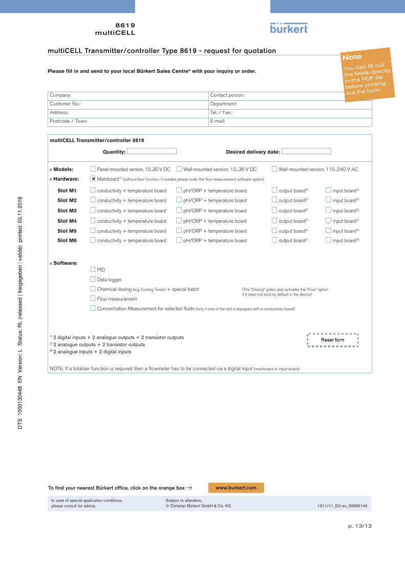
multiCELL Transmitter/controller Type 8619 - request for quotation
Please fill in and send to your local Bürkert Sales Centre* with your inquiry or order.
Company: Contact person:
Customer No.: Department:
Address: Tel. / Fax.:
Postcode / Town: E-mail:
multiCELL Transmitter/controller 8619
Quantity: Desired delivery date:
Models: Panel-mounted version, 12...30 V DC Wall-mounted version, 12...36 V DC Wall-mounted version, 110...240 V AC
Hardware: Mainboard1) (without flow function; if needed please order the flow measurement software option)
Slot M1 conductivity + temperature board pH/ORP + temperature board output board2) input board3)
Slot M2 conductivity + temperature board pH/ORP + temperature board output board2) input board3)
Slot M3 conductivity + temperature board pH/ORP + temperature board output board2) input board3)
Slot M4 conductivity + temperature board pH/ORP + temperature board output board2) input board3)
Slot M5 conductivity + temperature board pH/ORP + temperature board output board2) input board3)
Slot M6 conductivity + temperature board pH/ORP + temperature board output board2) input board3)
Software:
PID
Data logger
Chemical dosing (e.g. Cooling Tower) + special batch (The “Dosing” option also activates the “Flow” option if it does not exist by default in the device)
Flow measurement
Concentration Measurement for selected fluids (only if one of the slot is equipped with a conductivity board)
1) 2 digital inputs + 2 analogue outputs + 2 transistor outputs2) 2 analogue outputs + 2 transistor outputs3) 2 analogue inputs + 2 digital inputs
NOTE: If a totalizer function is required then a flowmeter has to be connected via a digital input (mainboard or input board)