the behaviour of single-storey industrial steel frames in fire

Project no: 99-018
Date: 2001-12-17
Version: Rev. A
Fire Safety Design ABPO Box 2170S - 220 02 LUNDSWEDEN
Org no.: 55 62 71 - 2165 Phone: 046-14 00 20Telefax: 046-14 00 30E-mail: [email protected]
Multi-storey Structures, Behaviour in Case of FireInitial Theoretical Analyses

Fire Safety Design AB Project no: 99-018Multi-storey Structures, Behaviour in Case of Fire Date: 2000-12-17Initial Theoretical Analyses Version: Rev. A
Page 1 of 86
Document Information
FSD Project no: 99-018
Document Title: Initial Theoretical Analyses
Project Title: Multi-storey Structures, Behaviour in Case of Fire
Document number: 99-018-0
Client:
Clients Ref:
Issued by: MSc Sebastian Jeansson / PhD Yngve Anderberg
Checked by: PhD Yngve Anderberg
Key words:
Report Status: Confidential ! Internal ! Open !
Rev. A 2001-12-17 Final version SJ/YA YA
0 2001-11-13 Final version SJ/YA YA
Draft 2001-03-05 Draft
Draft 2001-02-16 Draft
Draft 0 1999-10-05 Preliminary Draft
Version Date Issue Issued by Checked by

Fire Safety Design AB Project no: 99-018Multi-storey Structures, Behaviour in Case of Fire Date: 2001-12-17Initial Theoretical Analyses Version: Rev. A
Page 2 of 86
Contents
1 Introduction ....................................................................................................................... 4
1.1 Background................................................................................................................................ 41.2 Aim and Scope of Work ............................................................................................................ 41.3 Accomplishment and Planning.................................................................................................. 4
1.3.1 Sub-Project A .................................................................................................................... 51.3.2 Sub-Project B..................................................................................................................... 5
2 Initial Analyses .................................................................................................................. 5
2.1 Parameter Study for Columns.................................................................................................... 52.1.1 Standard Fire Exposure on ~1/4, 1/2, ~3/4 and 1/1 of the Steel Profile Circumference... 62.1.2 Slenderness ........................................................................................................................ 62.1.3 Axial Loading Degree with Different Eccentricities......................................................... 62.1.4 Partially Restrained Elongation......................................................................................... 62.1.5 Insulation ........................................................................................................................... 6
2.2 Parameter Study for Beams ....................................................................................................... 62.2.1 Standard Fire Exposure on ~1/4, 1/2, ~3/4 and 1/1 of the Steel Profile Circumference... 6
2.3 Verification Tests ...................................................................................................................... 62.4 Parameter Study of Frames........................................................................................................ 7
3 Properties of Steel ............................................................................................................. 7
3.1 Thermal Properties .................................................................................................................... 73.2 Mechanical Properties ............................................................................................................... 8
3.2.1 Stress - Strain Relationship ............................................................................................... 83.2.2 Compression/Tension Strength ......................................................................................... 93.2.3 Modulus of Elasticity (Young’s Modulus)...................................................................... 10
4 Fire Exposure .................................................................................................................. 10
4.1 Definition of ~1/4, 1/2, ~3/4 and 1/1 fire exposure................................................................. 104.2 ISO 834 standard fire exposure ............................................................................................... 114.3 Boundary Conditions............................................................................................................... 11
5 Modelling Steel Columns................................................................................................ 12
5.1 Definition of Slenderness ........................................................................................................ 135.2 Eccentricities ........................................................................................................................... 145.3 Degree of Loading ................................................................................................................... 15
6 Thermal Analysis............................................................................................................. 17
6.1 Super-Tempcalc....................................................................................................................... 176.2 Results from Thermal Analyses .............................................................................................. 18
7 Structural Analysis .......................................................................................................... 21
7.1 Global Collapse Analysis (GCA) ............................................................................................ 217.2 TCD - FIRE DESIGN.............................................................................................................. 28
7.2.1 SBEAM ........................................................................................................................... 287.2.2 COMPRES....................................................................................................................... 29
8 Structural Analyses of Columns...................................................................................... 32
8.1 Simulations .............................................................................................................................. 32
Fire Safety Design AB Project no: 99-018Multi-storey Structures, Behaviour in Case of Fire Date: 2001-12-17Initial Theoretical Analyses Version: Rev. A
Page 3 of 86
8.1.1 Structural Behaviour for Partially Exposed Columns ..................................................... 328.1.2 Structural Behaviour of Columns with Eccentric Loads................................................. 358.1.3 Columns with Partially Restrained Axial Elongation ..................................................... 368.1.4 Verification of Steel Quality, Profile Type and Slenderness as Design Parameters forColumns....................................................................................................................................... 408.1.5 Verification of Applied Degree of Loading .................................................................... 418.1.6 Verification of Applied Design Load and Initial Out-of-straightness............................. 41
8.2 Test .......................................................................................................................................... 428.2.1 Temperature Simulation of Steel Column Fire Test Conducted in UK .......................... 42
9 Structural Analyses of Beams.......................................................................................... 45
9.1 Simulations .............................................................................................................................. 459.1.1 Structural Behaviour for Partially Exposed Beams......................................................... 459.1.2 Verification of Applied Design Load.............................................................................. 46
9.2 Test (Beam with Concrete Slab).............................................................................................. 499.2.1 Temperature Simulation of Steel Beam Fire Test Conducted in UK.............................. 49
9.3 Continuous beams.................................................................................................................... 52
10 Analyses of Frame ........................................................................................................... 57
10.1 Frame Model........................................................................................................................ 5710.1.1 Geometry ..................................................................................................................... 5710.1.2 Boundary Conditions................................................................................................... 5910.1.3 Loading........................................................................................................................ 5910.1.4 Fire Exposure............................................................................................................... 60
10.2 Fully Fire-Exposed Frame ................................................................................................... 6110.3 Single-Compartmentation Fire Exposure ............................................................................ 65
11 Conclusions ..................................................................................................................... 72
11.1 Columns............................................................................................................................... 7211.2 Beams .................................................................................................................................. 7311.3 Frames ................................................................................................................................. 73
12 Condensed Literature Review ......................................................................................... 75
12.1 A: Experience of structural behaviour and extent of damages in real building fires .......... 7512.2 B: Fire tests on structures .................................................................................................... 7612.3 C: Basic research on mechanical properties and on behaviour of structural elements .. 7712.4 D: FEM-modelling and computer simulation of fire tests................................................... 7812.5 E: Structural fire design methods ........................................................................................ 7912.6 References to Condensed Literature Review ...................................................................... 80
A Experience of structural behaviour and extent of damages in real building fires ........... 80B Fire tests of structures...................................................................................................... 80C Basic research on mechanical properties and on behaviour of structural elements ........ 81D FEM-modelling and computer simulation of fire tests.................................................... 81E Structural fire design methods......................................................................................... 82
13 References ....................................................................................................................... 85

Fire Safety Design AB Project no: 99-018Multi-storey Structures, Behaviour in Case of Fire Date: 2001-12-17Initial Theoretical Analyses Version: Rev. A
Page 4 of 86
1 Introduction
This report is part of the project Multi-storey Structures, Behaviour in Case of Fire which is aproject held in co-operation between Fire Safety Design AB and the Swedish Institute of SteelConstruction and covers the initial computer simulations of single columns.
The goal of the project is to improve the understanding of the behaviour of fire exposed steelstructures and to prepare a design basis for a future design handbook for fire exposed steelconstructions.
1.1 Background
During the last years important changes have occurred in the steel construction field. There are signsthat imply that more optimised constructional fire state solutions could be developed. This has beenconfirmed by a number of occurred fires in multi-storey buildings /15, 16/, where the fire resistancetime has turned out to be better than can be calculated using standard methods that are based onstandard tests of single members such as beams and columns. Further understanding can be gainedfrom documented full-scale tests /17, 18, 19/.
The design rules that are applied today are based on simplifications, for instance that the cross-sectional temperature over the steel profile is constant and that each single member is designed atfire state. This is rarely the case in reality. Usually just one part is subjected to fire exposure andlarge temperature deviations are present. This gives rise to a different behaviour of a partiallyexposed construction. The following issues are of main interest:
• The behaviour of single columns of frameworks at different types of exposure• The effect of beams, columns and systems of joists that are partially constrained• The behaviour of multi-storey constructions in fire• To identify redundant members• What kind of members should be given priority with respect to loadbearing function• The magnitude of load redistribution in structures at large deformations• How the support conditions change at intersections
1.2 Aim and Scope of Work
The goal of this initial study is to delineate and improve the understanding of the behaviour of fireexposed steel structures and to prepare a design basis for a future design handbook for fire exposedsteel constructions. The outcome of the final work includes:
• To increase the understanding of the collapse behaviour of steel columns in fire• To analyse the influence of partially restrained thermal elongation of beams, columns and frames• To develop analysis models for multi-storey steel frames in fire, considering the different
behaviour at large deformations• To give practical recommendations of the combination of measurements that gives a building
sufficient safety in the fire state
1.3 Accomplishment and Planning
A thorough literature study and a knowledge specification of documented theoretical andexperimental studies are important for theoretical part of the work. The initial literature study is

Fire Safety Design AB Project no: 99-018Multi-storey Structures, Behaviour in Case of Fire Date: 2001-12-17Initial Theoretical Analyses Version: Rev. A
Page 5 of 86
conducted by Fire Safety Design AB, FSD, with literature support from the Swedish Institute ofSteel Construction, SBI. FSD and SBI are to carry out the project, which is divided into two clearlydefined and separate sub-projects A and B, in co-operation.
The analytical part with computer simulations including documentation is divided in the followingparts:
• Fire tests• Behaviour of columns• Behaviour of beams • Behaviour of frames
1.3.1 Sub-Project A
Fire Safety Design AB will perform initial verification analyses, computer simulations of individualmembers. Results from some chosen fire tests on loaded columns, such as measured fire resistancetimes and deformations will be done to verify the models. This will initially be done for profiles thatare exposed on all surfaces, but comparisons of tests for cases with partial exposure is desired too.Computer simulations of the collapse behaviour will be done for steel columns that are free toexpand.A parameter study is to be performed to analyse how different factors such as fire exposure,slenderness, eccentricity and initial out of straightness influence the load-bearing capacity of steelcolumns of different geometrical properties in fire. Computer simulations of the behaviour ofcolumns and frames with columns being subjected to partial axial restraint are to be done as well asa couple of simulations of locally exposed frames. Specially developed computer tools, Super-Tempcalc and Global Collapse Analysis will be used for studies of temperature development andstructural response. New findings will be used to develop improved and new methods for fire design.
1.3.2 Sub-Project B
The Swedish Institute of Steel Construction will study and develop analysis models for multi-storeysteel frames in fire, considering the changes in behaviour due to large deformations with the help ofECSC’s experiences and give practical recommendations about the combinations of measurementsthat gives a building sufficient safety in the case of fire.
2 Initial Analyses
2.1 Parameter Study for Columns
A parameter study was carried out to analyse how different factors effect the load-bearing capacityfor geometrical differences of fire:
• Fire exposure (ISO 834)• Slenderness• Axial load levels with different eccentricities• Partially restrained elongation• Insulation (intumescent paint)
The initial analyses can be found in sections 8 - 10.

Fire Safety Design AB Project no: 99-018Multi-storey Structures, Behaviour in Case of Fire Date: 2001-12-17Initial Theoretical Analyses Version: Rev. A
Page 6 of 86
2.1.1 Standard Fire Exposure on ~1/4, 1/2, ~3/4 and 1/1 of the Steel ProfileCircumference
Standard fire according to ISO 834 is to be focused on exposure of 1/1 (100%) of the circumference.Partially exposed columns will be analysed separately.
2.1.2 Slenderness
Five different values of slenderness will be studied for columns: 0, 0.5, 0.75, 1.0 and 1.5.
2.1.3 Axial Loading Degree with Different Eccentricities
The degree of axial loading is chosen to 60%, 50%, 40% and 25% of the characteristic bucklingcompression resistance load at room temperature, 20 °C. The characteristic resistance loadcorresponds to design in the fire state, as opposed to the normal design resistance load.The eccentricity is chosen to 0, ± 3 cm and ± 5 cm. An initial out of straightness, defined by the firsteigenmode with a maximum amplitude of 1/400 of the column length, is added for all columns. Thedirection of the out of straightness is chosen to that of the fire-related deflections.
2.1.4 Partially Restrained Elongation
The influence of partially restrained axial elongation is studied for 100% fire exposure, aneccentricity of 0 and with slenderness values of 0.5 and 1.0. The calculations are performed withinitial axial degrees of freedom of 0.8, 0.9 and 1.0. A value of 1.0 means free elongation and 0means totally restrained. Further analyses include a frame under influence of local fire exposure.
2.1.5 Insulation
Steel columns to be simulated are insulated in order to control the development of temperatures. Anintumescent paint is chosen to achieve about 60 minutes of fire resistance time for 100% exposureand a slenderness of 1.0. The frames are modelled without insulation.
2.2 Parameter Study for Beams
• Fire exposure (ISO 834 and natural fires)• Insulation (intumescent paint)
2.2.1 Standard Fire Exposure on ~1/4, 1/2, ~3/4 and 1/1 of the Steel ProfileCircumference
Standard fire according to ISO 834 is to be focused on exposure of ~1/4 - ~3/4 of the circumference.
2.3 Verification Tests
Simulations of fire tests were done for verification of the non-linear GCA approach andcorresponding, applicable design approach. Measured results from fire tests of unloaded and loadedsteel columns in terms of stress, strain and deformations are compared to the results from computersimulations of identical conditions. This concerns profiles that are exposed on all surfaces and caseswhere the degree of fire exposure vary.
Fire Safety Design AB Project no: 99-018Multi-storey Structures, Behaviour in Case of Fire Date: 2001-12-17Initial Theoretical Analyses Version: Rev. A
Page 7 of 86
Considered relevant fire tests were:
• Tests performed in England with standard fire exposure and natural fires.
• Some loaded steel columns that have been tested in fire by Nils Forsén and Björn Aasen at the
Norwegian Fire Research Laboratory
• Experimental results found in the literature study.
Full scale fire tests of a beam and a fully exposed column conducted at Firto Borehamwood, U.K.1984, were finally chosen for simulations. Tests of partially exposed columns conducted at FirtoBorehamwood involved a wall which was impossible to simulate since the columns reached the wallwithin a few minutes after which the direction of horizontal deformations was reversed.
The results from the simulations can be found in sections 8.2 and 9.2.
2.4 Parameter Study of Frames
One 3-storey steel frame was modelled. The different scenarios were
• Fully fire exposed• Exposure in a single compartment
The results can be found in section 10.2.
3 Properties of Steel
The knowledge of thermal and mechanical properties are necessary in the thermal and structuralanalysis of fire-exposed steel columns. The temperature-dependence of the material properties aredescribed in this section.
3.1 Thermal Properties
Thermal properties are essential to heat transfer calculations. These are, essentially, heatconductivity, heat capacitivity and thermal expansion, all of which vary with increasing temperature.
Thermal capacitivity is defined as the product between specific heat and density. It expresses themagnitude of energy storage potential of the material. Typical insulation products feature lowthermal conductivity, whilst metals like steel are excellent conductors. The density of steel is 7850kg/m3.
The thermal properties of steel used in the analyses are illustrated in figure 3-1.

Fire Safety Design AB Project no: 99-018Multi-storey Structures, Behaviour in Case of Fire Date: 2001-12-17Initial Theoretical Analyses Version: Rev. A
Page 8 of 86
� ��� ��� ��� ��� ���� �����
��
��
��
��
��
��
�� ��� �°�
°
� ��� ���� �����
����
����
����
����
����
����
��� ����°�
���
��� � �������������
�°��
a) b)
Figure 3-1 a) Thermal conductivity of steel /10/.b) Thermal capacitivity of steel /10/.
Steel, being an isotropic material, has equal properties in all directions. One of these is the ability toexpand when subjected to a temperature elevation. This expansion will cause a strain in the material.The thermal expansion can be described by:
Tth ∆αε = (eq. 3-1)
The variable α can be expressed in many ways, for instance as a constant or as a linear variation ofthe temperature or as a polynomial function of the temperature.
The polynomial expression of the thermal elongation is described by
2854 10401021104162 T.T..th−−− ⋅+⋅+⋅−=ε (eq. 3-2)
The property of expanding is of particular interest when considering complex structures with fixedend connections. The rigidity of connections and external attachment restricts desired expansion,thus generating constraint stresses.
3.2 Mechanical Properties
Stress-strain relationships (σ-ε curves) at elevated temperatures are must be known to be able tocalculate stress and deformations of fire exposed shell structures. Tension and compression strengthand modulus of elasticity as function of temperature can be derived from σ-ε curves.
3.2.1 Stress - Strain Relationship
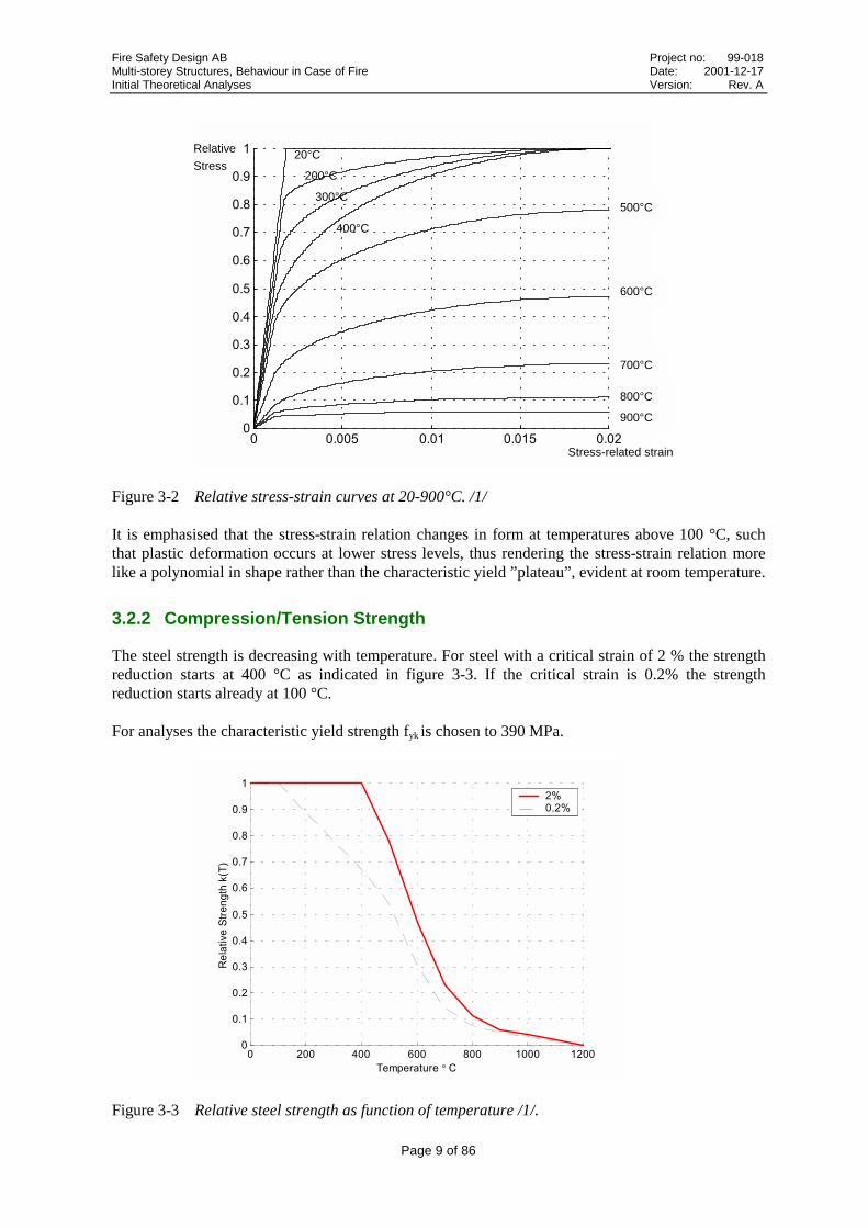
The adopted stress-strain relationship for steel follows the idealised analytical expression proposedin Eurocode /1/. Each steel core temperature has its own stress-strain curve. Figure 3-2 displays thestress-strain curves for steel at different temperatures.
Fire Safety Design AB Project no: 99-018Multi-storey Structures, Behaviour in Case of Fire Date: 2001-12-17Initial Theoretical Analyses Version: Rev. A
Page 9 of 86
� ����� ���� ����� �����
���
���
���
���
���
���
���
���
��
�
Figure 3-2 Relative stress-strain curves at 20-900°C. /1/
It is emphasised that the stress-strain relation changes in form at temperatures above 100 °C, suchthat plastic deformation occurs at lower stress levels, thus rendering the stress-strain relation morelike a polynomial in shape rather than the characteristic yield ”plateau”, evident at room temperature.
3.2.2 Compression/Tension Strength
The steel strength is decreasing with temperature. For steel with a critical strain of 2 % the strengthreduction starts at 400 °C as indicated in figure 3-3. If the critical strain is 0.2% the strengthreduction starts already at 100 °C.
For analyses the characteristic yield strength fyk is chosen to 390 MPa.
� ��� ��� ��� ��� ���� �����
���
���
���
���
���
���
���
���
��
�
!� ����"��#$����%�&
��� ����°��
�'�����'
Figure 3-3 Relative steel strength as function of temperature /1/.
900°C
800°C
700°C
600°C
500°C
400°C
20°C
200°C
300°C
Stress-related strain
Relative
Stress

Fire Safety Design AB Project no: 99-018Multi-storey Structures, Behaviour in Case of Fire Date: 2001-12-17Initial Theoretical Analyses Version: Rev. A
Page 10 of 86
3.2.3 Modulus of Elasticity (Young’s Modulus)
The modulus of elasticity, much like the strength, shows a decreasing path as the temperatureincreases in the steel material. The decreasing branch starts at 100 °C. At 1200 °C all initial stiffnessis lost. The modulus of elasticity is 210 GPa.
The relationship between modulus of elasticity and temperature is given in figure 3-4.
� ��� ��� ��� ��� ���� �����
���
���
���
���
�
��� ����°�
!� ����()���*�(+�� *��������,- %�&
Figure 3-4 Relative modulus of elasticity as function of temperature. /1/
4 Fire Exposure
4.1 Definition of ~1/4, 1/2, ~3/4 and 1/1 fire exposure
“~1/4” refers to 1-sided fire exposure, “1/2” refers to exposure on half of the steel profilecircumference, “~3/4” refers to 3-sided fire exposure and “1/1” refers to 4-sided fire exposure. Thesymbol “~” (tilde character) should read “approximately”. The actual percentage of fire exposedcircumference for 1-sided and 3-sided exposure depends on profile type.
In order to protect the exposed surfaces of the steel profiles, HEB300 and HEB200, a layer ofintumescent paint (Hensotherm 4 Ks) is applied. This means that the temperature increase of thesteel will be delayed and a fire resistance of about 50-60 minutes for 100% exposure and 40 % loadis obtained. Four cases of partial fire exposure are studied viz. ~1/4 (19 %), 1/2 (50 %) , ~3/4 (83%)and 1/1 (100%), all defined as percentages of exposed surface for the profile HEB300. 19%exposure means that only the lower part of the bottom flange is exposed and the rest is not in contactwith fire. This is arranged by surrounding the unexposed part with a material of concrete-type, whichis illustrated in figure 4-1. 50% means that half of the profile is exposed and ~3/4 (83 %) means thatonly the upper part of the upper flange is not exposed to fire. The thermal properties of concretewere taken according to /10/.

Fire Safety Design AB Project no: 99-018Multi-storey Structures, Behaviour in Case of Fire Date: 2001-12-17Initial Theoretical Analyses Version: Rev. A
Page 11 of 86
~1/4 (19%) 1/2 (50%) ~3/4 (83%) 1/1 (100%)
Figure 4-1 Four cases of fire exposure studied.
4.2 ISO 834 standard fire exposure
The standard ISO 834 time temperature development is described by
0 t )1480log(345)( 0 >++⋅= TttT (eq. 4-1)
where
t = time (h)T(t) = gas temperature at time t (°C)T0 = initial temperature (°C)
The time temperature development is presented in a chart in figure 4-2.
� � � � � ��
���
���
���
���
����
����
������
. *���� ���� °�
Figure 4-2 Time-temperature development of ISO 834 fire exposure /2/.
4.3 Boundary Conditions
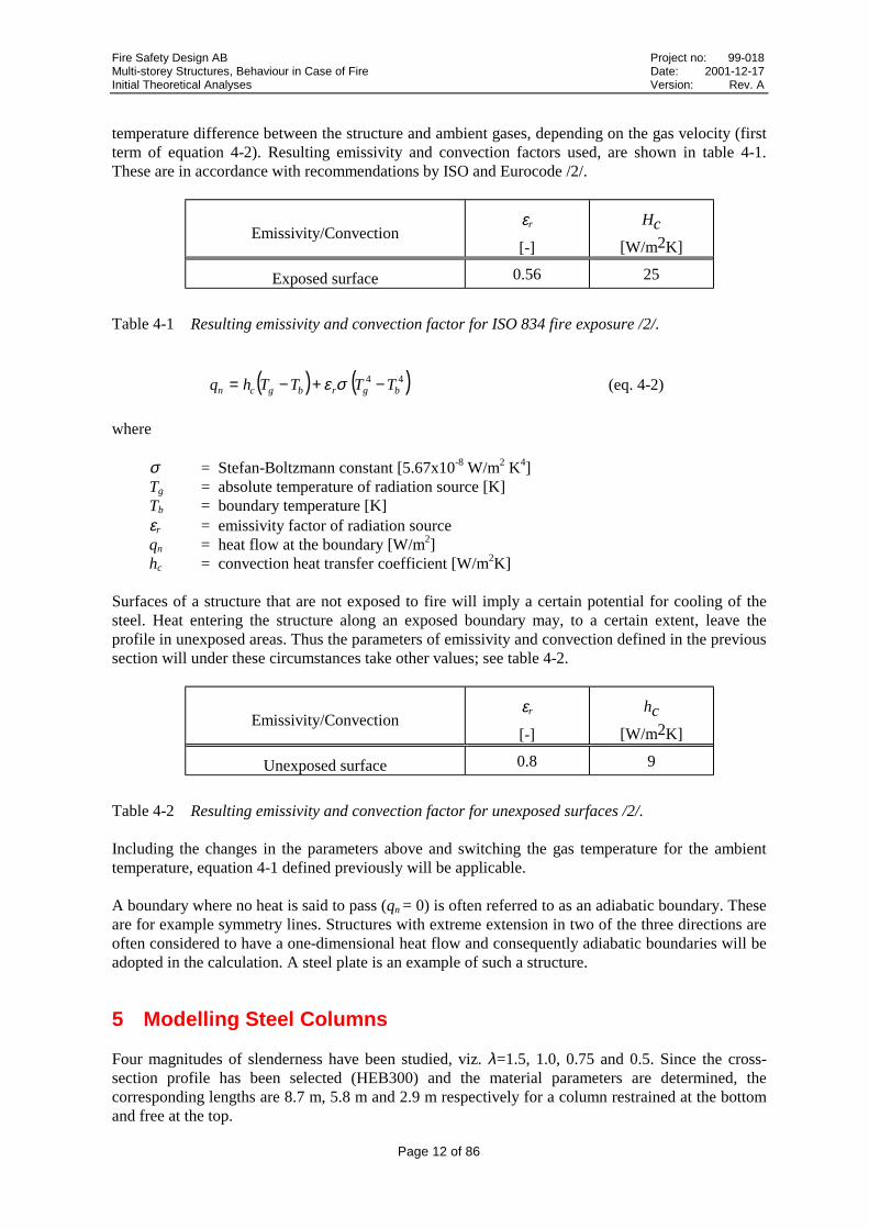
The heat is transferred from the fire gases to the exposed structure through radiation and convection(see equation 4-2). The radiation, which dominates at high temperatures, is expressed by theresultant emissivity factor (second term of equation 4-2). The convection is calculated from the
Fire Safety Design AB Project no: 99-018Multi-storey Structures, Behaviour in Case of Fire Date: 2001-12-17Initial Theoretical Analyses Version: Rev. A
Page 12 of 86
temperature difference between the structure and ambient gases, depending on the gas velocity (firstterm of equation 4-2). Resulting emissivity and convection factors used, are shown in table 4-1.These are in accordance with recommendations by ISO and Eurocode /2/.
Emissivity/Convectionεr
[-]
Hc
[W/m2K]
Exposed surface 0.56 25
Table 4-1 Resulting emissivity and convection factor for ISO 834 fire exposure /2/.
( ) ( )44 bgrbgcn TTTThq −+−= σε (eq. 4-2)
where
σ = Stefan-Boltzmann constant [5.67x10⁻⁸ W/m2 K4]Tg = absolute temperature of radiation source [K]Tb = boundary temperature [K]εr = emissivity factor of radiation sourceqn = heat flow at the boundary [W/m2]hc = convection heat transfer coefficient [W/m2K]
Surfaces of a structure that are not exposed to fire will imply a certain potential for cooling of thesteel. Heat entering the structure along an exposed boundary may, to a certain extent, leave theprofile in unexposed areas. Thus the parameters of emissivity and convection defined in the previoussection will under these circumstances take other values; see table 4-2.
Emissivity/Convectionεr
[-]
hc
[W/m2K]
Unexposed surface 0.8 9
Table 4-2 Resulting emissivity and convection factor for unexposed surfaces /2/.
Including the changes in the parameters above and switching the gas temperature for the ambienttemperature, equation 4-1 defined previously will be applicable.
A boundary where no heat is said to pass (qn = 0) is often referred to as an adiabatic boundary. Theseare for example symmetry lines. Structures with extreme extension in two of the three directions areoften considered to have a one-dimensional heat flow and consequently adiabatic boundaries will beadopted in the calculation. A steel plate is an example of such a structure.
5 Modelling Steel Columns
Four magnitudes of slenderness have been studied, viz. λ=1.5, 1.0, 0.75 and 0.5. Since the cross-section profile has been selected (HEB300) and the material parameters are determined, thecorresponding lengths are 8.7 m, 5.8 m and 2.9 m respectively for a column restrained at the bottomand free at the top.

Fire Safety Design AB Project no: 99-018Multi-storey Structures, Behaviour in Case of Fire Date: 2001-12-17Initial Theoretical Analyses Version: Rev. A
Page 13 of 86
Steel cross-sections are generally divided into four classes depending on their ability to form aplastic hinge. The method is practically the same in all design codes; here the Eurocode version isrepresented.
5.1 Definition of Slenderness
Slenderness expresses the degree of sensitivity to the buckling phenomenon (flexural buckling), andlinks the strength, the length, the stiffness and the cross-section dimensions together. Theslenderness ratio, λ, is defined in equation 5-1. The ratio relates the characteristic compressionresistance, Nc.R, to the critical axial buckling force, Ncr, according to the Euler buckling theory.
E
f
i
l
N
fA yc
cr
y
πλ =
⋅= (eq. 5-1)
yR.c fAN ⋅= (eq. 5-2)
2
2
ccr
l
EIN
π= (eq. 5-3)
where
cl = buckling length of column
Equation 5-1 indicates the turning point between two different modes of failure. Values of λexceeding 1.0 applies to a buckling failure mainly in accordance with equation 5-3 (flexuralbuckling). For lower values of λ the failure will be governed by the cross-sectional stress reachingthe yield strength. The following parameters are all affecting steel columns in one way or the other:
• initial out of straightness• unintentional eccentricity• secondary geometrical effects• initial stresses• plasticizing during the buckling process
Taking these effects into account, the curve found in figure 5-1 is obtained.

Fire Safety Design AB Project no: 99-018Multi-storey Structures, Behaviour in Case of Fire Date: 2001-12-17Initial Theoretical Analyses Version: Rev. A
Page 14 of 86
� ��� ��� ��� ��� � ��� ��� ��� ��� ��
���
���
���
���
���
���
���
���
��
�
λ
χ
/
�
)
Figure 5-1 Reduction factor as function of slenderness for cross-section types a-d /12/.
The reduction factor in figure 5-1 is denoted χ and is a function of the slenderness ratio and dependson the type of cross-section (a-d). It can be obtained in ENV 1993-1-1 or in BSK 94 (named ω inBSK 94).
The characteristic buckling resistance of a compression member can be defined as:
R.cR.b NN ⋅= χ (eq. 5-4)
Slenderness and stiffness, defined as the product EI, are two essential parameters concerningcolumns. A decrease in stiffness will cause an increase in slenderness, and vice versa.
5.2 Eccentricities
Eccentricities as initial out of straightness and thermal bending will vary along the length of thecolumn. These eccentricities influence the behaviour of fire exposed columns because it willimplicate a moment due to the axial load in accordance with equation 5-5.
eNM ⋅= (eq. 5-5)
The columns were modelled structurally with a geometrical eccentricity in the nodes to compensatefor initial out of straightness, as indicated in figure 5-3. The initial out of straightness is modelledaccording to the first eigenmode with the maximum deflection taken as the system length divided by400.
The difference in temperature over the cross-section implies a varying desire to expand thermally.The Bernoulli assumption states that the cross-section plane remains perpendicular to the beam axisduring the progress of deformation. It is thus concluded that the beam axis must bend and a thermaleccentricity is obtained. The stress contribution from the moment will be superposed to thecompression stress generated by the axial force. During the progress of the fire scenario thetemperature gradient grows larger and the ”thermal eccentricity” is increasing continuously, with

Fire Safety Design AB Project no: 99-018Multi-storey Structures, Behaviour in Case of Fire Date: 2001-12-17Initial Theoretical Analyses Version: Rev. A
Page 15 of 86
escalating stresses as a result, and finally the critical design strength will be attained. This is thereason why partial fire exposure is so critical to a column’s load-bearing capacity and thus needs tobe investigated thoroughly in order to determine the most appropriate approach of design. Presuminga structural model as showed in figure 5-3 the total thermal eccentricity, eth, is indicated.
e0
Node L ∆Τ
h
eth
FIRE
Figure 5-3 Structural model of studied columns.Lower end fixed, upper end free. Initialeccentricity modelled in the nodes.
Indication of thermal eccentricity, εth,descending from the temperaturedifference between the flanges, ∆T, causedby partial fire exposure.
5.3 Degree of Loading
The degree of loading is taken as a percentage of the characteristic buckling resistance load in thefire state, represented by the expression defined in equation 5-4. Appropriate magnitudes of relativeloading were found to be 25%, 40%, 50% and 60%. Supplementary analyses were done with arelative loading between 0-80%.
Fire Safety Design AB Project no: 99-018Multi-storey Structures, Behaviour in Case of Fire Date: 2001-12-17Initial Theoretical Analyses Version: Rev. A
Page 16 of 86
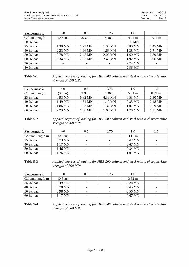
Slenderness λ ~0 0.5 0.75 1.0 1.5Column length (0.3 m) 2.37 m 3.56 m 4.74 m 7.11 m 0 % load - - - 0 MN -25 % load 1.39 MN 1.23 MN 1.03 MN 0.80 MN 0.45 MN40 % load 2.23 MN 1.96 MN 1.66 MN 1.28 MN 0.71 MN50 % load 2.78 MN 2.45 MN 2.07 MN 1.60 MN 0.89 MN60 % load 3.34 MN 2.95 MN 2.48 MN 1.92 MN 1.06 MN70 % load - - - 2.24 MN -80 % load - - - 2.56 MN -
Table 5-1 Applied degrees of loading for HEB 300 column and steel with a characteristicstrength of 390 MPa.
Slenderness λ ~0 0.5 0.75 1.0 1.5Column length (0.3 m) 2.90 m 4.36 m 5.81 m 8.71 m25 % load 0.93 MN 0.82 MN 4.36 MN 0.53 MN 0.30 MN40 % load 1.49 MN 1.31 MN 1.10 MN 0.85 MN 0.48 MN50 % load 1.86 MN 1.63 MN 1.37 MN 1.07 MN 0.59 MN60 % load 2.23 MN 1.96 MN 1.66 MN 1.28 MN 0.71 MN
Table 5-2 Applied degrees of loading for HEB 300 column and steel with a characteristicstrength of 260 MPa.
Slenderness λ ~0 0.5 0.75 1.0 1.5Column length m (0.3 m) - - 3.12 m -25 % load 0.73 MN - - 0.42 MN -40 % load 1.17 MN - - 0.67 MN -50 % load 1.46 MN - - 0.84 MN -60 % load 1.76 MN - - 1.01 MN -
Table 5-3 Applied degrees of loading for HEB 200 column and steel with a characteristicstrength of 390 MPa.
Slenderness λ ~0 0.5 0.75 1.0 1.5Column length m (0.3 m) - - 3.82 m -25 % load 0.49 MN - - 0.28 MN -40 % load 0.78 MN - - 0.45 MN -50 % load 0.98 MN - - 0.56 MN -60 % load 1.17 MN - - 0.67 MN -
Table 5-4 Applied degrees of loading for HEB 200 column and steel with a characteristicstrength of 260 MPa.
Fire Safety Design AB Project no: 99-018Multi-storey Structures, Behaviour in Case of Fire Date: 2001-12-17Initial Theoretical Analyses Version: Rev. A
Page 17 of 86
6 Thermal Analysis
The following information is essential when calculating nodal temperatures as function of timeduring a specified fire scenario:
• thermal properties• boundary conditions• fire exposure
The key engineering tool in this analytical procedure is the finite element temperature calculationprogram, Super-Tempcalc, which facilitates calculations of heat transfer, temperature redistributionand temperature development in modelled materials. The features and background theory of Super-Tempcalc are described in detail in section 6.1.
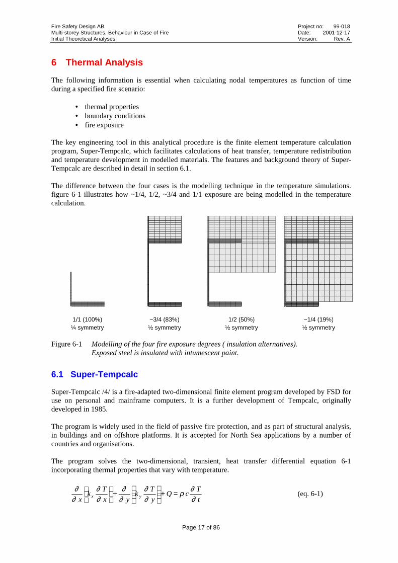
The difference between the four cases is the modelling technique in the temperature simulations.figure 6-1 illustrates how ~1/4, 1/2, ~3/4 and 1/1 exposure are being modelled in the temperaturecalculation.
1/1 (100%)¼ symmetry
~3/4 (83%)½ symmetry
1/2 (50%)½ symmetry
~1/4 (19%)½ symmetry
Figure 6-1 Modelling of the four fire exposure degrees ( insulation alternatives).Exposed steel is insulated with intumescent paint.
6.1 Super-Tempcalc
Super-Tempcalc /4/ is a fire-adapted two-dimensional finite element program developed by FSD foruse on personal and mainframe computers. It is a further development of Tempcalc, originallydeveloped in 1985.
The program is widely used in the field of passive fire protection, and as part of structural analysis,in buildings and on offshore platforms. It is accepted for North Sea applications by a number ofcountries and organisations.
The program solves the two-dimensional, transient, heat transfer differential equation 6-1incorporating thermal properties that vary with temperature.
t
TcQ
y
Tk
yx
Tk
x yx
∂∂ρ
∂∂
∂∂
∂∂
∂∂ =+
+
(eq. 6-1)

Fire Safety Design AB Project no: 99-018Multi-storey Structures, Behaviour in Case of Fire Date: 2001-12-17Initial Theoretical Analyses Version: Rev. A
Page 18 of 86
where
T = temperature [°C]kx, ky = thermal conductivity [W/m°C]c = specific thermal capacity [J/kg °C]ρ = density [kg/m3]Q = internal heat generation [W/m3]
The program allows the use of rectangular or triangular finite elements, in cylindrical or rectangularco-ordinates. Heat transferred by convection and radiation at the boundaries can be modelled as afunction of time. Structures comprising several materials can be analysed and the heat absorbed byany existing void in the structure is also taken into account.
A materials properties database is integrated with the main program. Also integrated with theprogram are pre- and post-processors which allow fast and user-friendly input/output procedures.The pre-processor generates the finite element division and retrieves the relevant information fromthe database for use in the calculation. Finally, the post-processor presents the results graphically onscreen or on plotter in a variety of forms, including time-temperature curves, isotherms, andtemperature gradients.
6.2 Results from Thermal Analyses
The steel profile has been subjected to a heat transfer calculation for a given fire scenario, resultingin a cross-sectional temperature gradient over time. The temperature development of the profiledenotes an essential input data for the subsequent global collapse analysis. Gradients over the HEB300 profile height can be found for the four different exposure alternatives in figures 6-2 – 6-5. Thegradient for the used profile HEB 200 with 100% exposure is presented in figure 6-6.
� ��� ��� ��� ��� ��� ��� ��� ��� �� �����
����
���
����
���
����
��� � � �� �� �� �� �� ������%�#&
��� ����%0�&
1�(+���2�$���%
&
Figure 6-2 100 % fire exposure. Temperature gradient along the height of the HEB300 profileafter 0, 5, 10, 20 40, 60, 80 and 120 minutes.

Fire Safety Design AB Project no: 99-018Multi-storey Structures, Behaviour in Case of Fire Date: 2001-12-17Initial Theoretical Analyses Version: Rev. A
Page 19 of 86
� ��� ��� ��� ��� ��� ��� ��� ��� �� �����
����
���
����
���
����
��� � � �� �� �� �� �� ������%�#&
��� ����%0�&
1�(+���2�$���%
&
Figure 6-3 ~3/4 (83 %) fire exposure. Temperature gradient along the height of the HEB300profile after 0, 5, 10, 20 40, 60, 80 and 120 minutes.
� ��� ��� ��� ��� ��� ��� ��� ��� �� �����
����
���
����
���
����
��� ������������ ������%�#&
��� ����%0�&
1�(+���2�$���%
&
Figure 6-4 1/2 (50 %) fire exposure. Temperature gradient along the height of the HEB 300profile after 0, 5, 10, 20 40, 60, 80 and 120 minutes.

Fire Safety Design AB Project no: 99-018Multi-storey Structures, Behaviour in Case of Fire Date: 2001-12-17Initial Theoretical Analyses Version: Rev. A
Page 20 of 86
� �� ��� ��� ��� ��� ��� ��� ��� ��� ����
����
���
����
���
����
��� ������������������%�#&
��� ����%0�&
1�(+���2�$���%
&
Figure 6-5 ~1/4 (19 %) fire exposure. Temperature gradient along the height of the HEB300profile after 0, 5, 10, 20 40, 60, 80 and 120 minutes.
� ��� ��� ��� ��� ��� ��� ��� ��� �� �����
����
����
����
����
���
����
����
����
����
��� � � �� �� �� �� ��������%�#&
��� ����%0�&
1�(+���2�$���%
&
Figure 6-6 1/1 (100 %) fire exposure. Temperature gradient along the height of the HEB200profile after 0, 5, 10, 20 40, 60, 80 and 120 minutes.

Fire Safety Design AB Project no: 99-018Multi-storey Structures, Behaviour in Case of Fire Date: 2001-12-17Initial Theoretical Analyses Version: Rev. A
Page 21 of 86
7 Structural Analysis
The results of the thermal analysis are incorporated in the structural ditto for computerisedprediction of structural stability. Elevating temperatures affect the steel by reduced strength andmodulus of elasticity, stress-strain relationship and the ability to expand thermally.
The main tool for current analyses has been the program Global Collapse Analysis. Comparisons oftests have been done with Fire Design, the beam and column tools integrated in TCD.
Columns differ significantly from other structures, being subjected to effects from instability. Thismeans that failure generally occurs from the axial load reaching the critical load (equation 4-5), andnot from the cross-sectional strain attaining the yield limit. The primary task of a column is generallyto transfer loads vertically down to the foundation, i.e. columns in structures are carrying axial loads.This makes the column a very essential part of a structure.
7.1 Global Collapse Analysis (GCA)
In some elastic solid mechanics problems the governing differential equations are linear and with alinear form of stress-strain relationship. However, in fire-related structural problems the linearity ofconstitutive relations is not preserved. The problem is actually a combination of material non-linearity together with geometrical non-linearity.
Global Collapse Analysis (GCA) is a finite element program providing computer prediction of thestructural behaviour of load-bearing systems.
Essential input to the program comprise:
• cross-sectional geometry• cross-sectional time-temperature fields from thermal analysis• geometry (column and beam geometry)• boundary conditions (rigidity, external attachments)• material data (steel strength, variation of stress-strain relationship)• external loads
GCA is integrated with the temperature calculation program Super-Tempcalc, thus incorporatingsteel temperature field data versus time of the adopted fire scenario.
The overall stability of a structure, due to a local fire, can be analysed and global progressive andlocal collapse respectively, can be predicted. Upgrading of identified separate critical membersprovides possible extension of initially calculated fire resistance time. Under certain conditions localcollapses can be accepted.
Generation of restraint stresses and strains, due to rigid external connections combined with thethermal expansion in the steel, makes the model reasonably accurate.
Results in terms of stresses, strains, cross-sectional stiffness, deflections, displacements, forces andmoments may be presented at selected times through out the fire scenario.
The 2-dimensional Bernoulli beam element with 6 degrees of freedom is used in the finite elementmodel. The kinematic assumption of this element is that plane sections normal to the beam axisremain plane and normal to the beam axis during the deformation.

Fire Safety Design AB Project no: 99-018Multi-storey Structures, Behaviour in Case of Fire Date: 2001-12-17Initial Theoretical Analyses Version: Rev. A
Page 22 of 86
Figure 7-1 The Bernoulli beam element with 6 degrees of freedom.
The two differential equations that describe the beam element are:
0d
d
d
d =+
xqx
uEA
x(eq. 7-1)
and
0d
d
d
d
d
d2
2
2
2
2
2
=−+
yq
x
vP
x
vEI
x(eq. 7-2)
The symbols used are described in Table 7-1.
Symbol Quantity
EA Stiffness in beam axis directionEI Bending stiffness
u Displacement in beam axis direction
v Displacement in direction perpendicular to beam axis
xq Distributed load in beam axis direction
yq Distributed load perpendicular to beam axis
P Axial load
Table 7-1 Description of symbols.
With known value of the displacement in the direction perpendicular to beam axis equation theequilibrium when taking into account the non-linear geometrical second-order effect is given byequation 7-3 with symbols according figure 7-2.

Fire Safety Design AB Project no: 99-018Multi-storey Structures, Behaviour in Case of Fire Date: 2001-12-17Initial Theoretical Analyses Version: Rev. A
Page 23 of 86
−
−=
−=−=
=
=
x
vP
x
vEI
xQ
x
vEI
xx
Mx
vEIM
x
v
y d
d
d
d
d
d
d
d
d
d
d
d V
d
d
d
d
2
2
2
2
2
2
θ
(eq. 7-3)
Figure 7-2 Properties derived from equilibrium of beam segment ∆x.
With k defined as:
EI
Pk =
equation 7-2 becomes:
02 =+ "vkv IV for compression (eq. 7-4 a)
02 =− "vkv IV for tension (eq. 7-4 b)
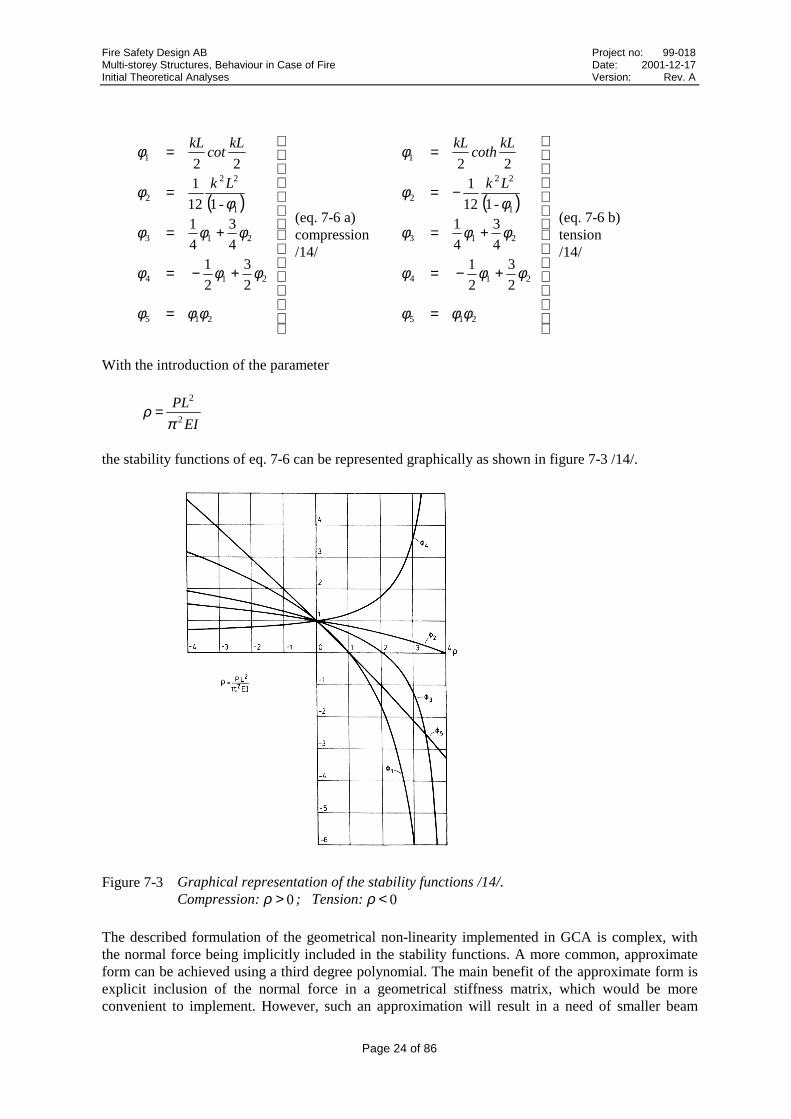
The solutions to equations 7-4 a and b are obtained by integrating twice. With the introduction ofstability functions φ1-φ5 according to equations 7-6 a and 7-6 b, the second-order beam elementmatrix can be written as:
−
−−−
−
−
−
−
=
422422
22532253
422322
22532253
460
260
6120
6120
0000
260
460
6120
6120
0000
φφφφ
φφφφ
φφφφ
φφφφ
L
EI
L
EI
L
EI
L
EI
L
EI
L
EI
L
EI
L
EI
L
EA
L
EA
L
EI
L
EI
L
EI
L
EI
L
EI
L
EI
L
EI
L
EI
L
EA
L
EA
K e (eq. 7-5)
Fire Safety Design AB Project no: 99-018Multi-storey Structures, Behaviour in Case of Fire Date: 2001-12-17Initial Theoretical Analyses Version: Rev. A
Page 24 of 86
( )
=
+−=
+=
=
=
215
214
213
1
22
2
1
2
3
2
1
4
3
4
1
-112
1
22
φφφ
φφφ
φφφ
φφ
φ
Lk
kLcot
kL
(eq. 7-6 a)compression/14/
( )
=
+−=
+=
−=
=
215
214
213
1
22
2
1
2
3
2
1
4
3
4
1
-112
1
22
φφφ
φφφ
φφφ
φφ
φ
Lk
kLcoth
kL
(eq. 7-6 b)tension/14/
With the introduction of the parameter
EI
PL2
2
πρ =
the stability functions of eq. 7-6 can be represented graphically as shown in figure 7-3 /14/.
Figure 7-3 Graphical representation of the stability functions /14/.Compression: 0>ρ ; Tension: 0<ρ
The described formulation of the geometrical non-linearity implemented in GCA is complex, withthe normal force being implicitly included in the stability functions. A more common, approximateform can be achieved using a third degree polynomial. The main benefit of the approximate form isexplicit inclusion of the normal force in a geometrical stiffness matrix, which would be moreconvenient to implement. However, such an approximation will result in a need of smaller beam
Fire Safety Design AB Project no: 99-018Multi-storey Structures, Behaviour in Case of Fire Date: 2001-12-17Initial Theoretical Analyses Version: Rev. A
Page 25 of 86
elements, especially in the situation of increasing temperatures. So the main benefit of theformulation described, is that more accurate results can be obtained using large elements.For assessment and storage of temperature gradients, strains, stresses and modulus of elasticity, across-sectional division of beams is done at each beam node.
The total strain can be written as:
creepthermaltotal εεεε σ ++= (eq. 7-7)
The temperature-dependent thermal strain is determined according to Eurocode 3:
4285 10416210401021 −−− ⋅−⋅+⋅= .T.T.thermalε ; C 750C 20 °<≤° T21011 −⋅= .thermalε ; C 860C 750 °≤≤° T
35 1026102 −− ⋅−⋅= .Tthermalε ; C 1200C 608 °≤<° T
(eq. 7-8)
The total cross-sectional strains are given by the calculated deformations from the system analyses ineach iteration as:
2
2
d
d
d
d
x
vy
x
utotal −=ε (eq. 7-9)
Modelling the creep strain has been excluded from the current GCA analyses, since effects of creepare included in the Eurocode 3 definition of the stress-related strain. Creep strain models in generaloften generates a large discrepancy between measured and predicted results.
The stress-related strain is determined from:
thermaltotal εεεσ −= (eq. 7-10)
The stress-related strain can be divided into elastic and plastic components.
For each cross-sectional point of all members in the system the stress-related strains are inserted inthe temperature-dependent expression describing the stress and modulus of elasticity as given byEurocode 3 (see figure 7-4). The number of points in the vertical direction of a beam cross-section istypically between 30-40. A member has two nodes, resulting in a need for 60-80 vertical cross-sectional points per member for storage of temperature, total strain, stress-related strain, thermalstrain, stress and modulus of elasticity. So for one member about 360-480 values are stored. Witheach structural member node having its own neutral layer at any given time, the neutral layer-relatedcontribution from a member to the system matrix must be transposed to a mutual reference point inorder for the solved system deformations to be equally related to nodes belonging to more than onemember. The reference point is chosen as the centroid of profiles. This means that two beams ofdifferent height are connected so that the centroid of both members are located in the same globalnode.

Fire Safety Design AB Project no: 99-018Multi-storey Structures, Behaviour in Case of Fire Date: 2001-12-17Initial Theoretical Analyses Version: Rev. A
Page 26 of 86
� ����� ���� ����� ���� ����� �����
���
�
���
�
���
�
���
�3���
�
1�(�(���(# ��4���
5��)�4���
� ����� ���� ����� ���� ����� �����
�
��
��3���
��
1�(�(���(# ��4���
5��)�4���
a) Stress-strain relationship. b) Modulus of elasticity-strain relationship.
Figure 7-4 Description of proportional and yield limits for stress-strain and modulus of elasticity-strain curves at 20 °C. /1/
The influences of the temperature and the escalating deformations are obvious when following thedecrease of the cross-sectional modulus of elasticity in figure 7-4 b. Load-bearing capacity iscontinuously lost as the time of the fire scenario proceeds. Eventually the stiffness of the memberwill be insufficient for provision of structural integrity under the applied loads.
The stiffness contribution etc. from each member is then defined according to eq. 7-5, transposedfrom the neutral layer of each adjacent member to a fixed point and then assembled to the globalsystem matrix. It should be emphasised that it is the modulus of elasticity and not the stresscomponent that is explicitly used to define the system matrix, although there is a relationshipbetween stress and modulus of elasticity as given by the Eurocode relationship.
For each time step, each constitutive iteration and each geometrical second-order iteration the finiteelement system is solved.
( ) ( )in
j,in
j,in , 1
1111 +
++++ = KafaaK (eq. 7-11)
where
K = global system matrixa = global displacement vectorf = global load vectorn = time step numberi = constitutive iteration numberj = geometrical stability iteration number
While in linear problems the solution is unique this is not the case in many non-linear situations. Asolution achieved may not necessarily be the solution sought. Different procedures with repeatedsolution of linear equations may be have to be considered for different problems.
There are no convergence problems involved in the geometrical, second-order iteration procedure.However, the constitutive non-linearity is of very complex nature. One important reason is thatstress-related strains in certain cross-sectional points can be either increasing or decreasing, even iftemperature is constantly increasing and the loading is constant.

Fire Safety Design AB Project no: 99-018Multi-storey Structures, Behaviour in Case of Fire Date: 2001-12-17Initial Theoretical Analyses Version: Rev. A
Page 27 of 86
Another problem is that the temperature-dependent reduction of modulus of elasticity is differentthan the yield stress reduction.
The iteration process in GCA is a modification of direct(Picard) iteration that has proven moresuccessful than the traditional Newton-Raphson method with stress-related strains possibly changingfrom decreasing to increasing during heating. The properties verified against convergence criteriacan be set to any combination of allowed stress and displacement deviation to allow for differentconditions. A compressed column with a free end would typically converge with displacementschosen as main criterion whereas the stress criterion would be better suited for a freely supportedbeam with large displacements near the time of collapse.
In the case of pure direct iteration 0a =n would be taken and the iteration process would proceed
without increments as
( )[ ] ( )in
in
in 1
1
111 +
−+
++ = afaKa (eq. 7-12)
Figure 7-5 Generic description of direct iteration for external forces. /5/
In the GCA iteration procedure, the path-dependency is stored in the system matrix, the displacementvector and corresponding total strains derived from previous time step. When entering a new timestep, the system matrix of the first constitutive iteration is derived from the total strains of the lasttime step and the thermal strains of the updated temperature field. The system is then solved asdescribed in eq. 7-12, but considering boundary conditions.
Global and local collapse analysis is governed by the determinant and the eigenvalue problemaccording to eq. 7-13, considering boundary conditions. Both are performed in each constitutiveiteration of each time step.
( ) 0aIK =− λ (eq. 7-13)
where
I = unity matrixλ = eigenvalue
Fire Safety Design AB Project no: 99-018Multi-storey Structures, Behaviour in Case of Fire Date: 2001-12-17Initial Theoretical Analyses Version: Rev. A
Page 28 of 86
7.2 TCD - FIRE DESIGN
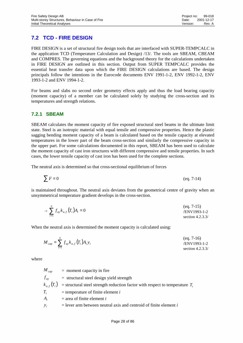
FIRE DESIGN is a set of structural fire design tools that are interfaced with SUPER-TEMPCALC inthe application TCD (Temperature Calculation and Design) /13/. The tools are SBEAM, CBEAMand COMPRES. The governing equations and the background theory for the calculations undertakenin FIRE DESIGN are outlined in this section. Output from SUPER TEMPCALC provides theessential heat transfer data upon which the FIRE DESIGN calculations are based. The designprincipals follow the intentions in the Eurocode documents ENV 1991-1-2, ENV 1992-1-2, ENV1993-1-2 and ENV 1994-1-2.
For beams and slabs no second order geometry effects apply and thus the load bearing capacity(moment capacity) of a member can be calculated solely by studying the cross-section and itstemperatures and strength relations.
7.2.1 SBEAM
SBEAM calculates the moment capacity of fire exposed structural steel beams in the ultimate limitstate. Steel is an isotropic material with equal tensile and compressive properties. Hence the plasticsagging bending moment capacity of a beam is calculated based on the tensile capacity at elevatedtemperatures in the lower part of the beam cross-section and similarly the compressive capacity inthe upper part. For some calculations documented in this report, SBEAM has been used to calculatethe moment capacity of cast iron structures with different compressive and tensile properties. In suchcases, the lower tensile capacity of cast iron has been used for the complete sections.
The neutral axis is determined so that cross-sectional equilibrium of forces
F =∑ 0 (eq. 7-14)
is maintained throughout. The neutral axis deviates from the geometrical centre of gravity when anunsymmetrical temperature gradient develops in the cross-section.
( ) 01
=→∑=
ii
n
if,aay ATkf
(eq. 7-15)/ENV1993-1-2section 4.2.3.3/
When the neutral axis is determined the moment capacity is calculated using:
( ) iii
n
if,aaycap yATkfM ∑
=
=1
(eq. 7-16)/ENV1993-1-2section 4.2.3.3/
where
capM = moment capacity in fire
ayf = structural steel design yield strength
( )if,a Tk = structural steel strength reduction factor with respect to temperature iT
iT = temperature of finite element i
iA = area of finite element i
iy = lever arm between neutral axis and centroid of finite element i

Fire Safety Design AB Project no: 99-018Multi-storey Structures, Behaviour in Case of Fire Date: 2001-12-17Initial Theoretical Analyses Version: Rev. A
Page 29 of 86
Based on the characteristic yield strength values, the design strength in fire design can be calculatedusing equation 7-17. The material design strength values for fire design should be employed inequations 7-15 and 7-16.
fi,mfi,n
fi,cfi,d
ff
γγ = (eq. 7-17)
where
fi,df = design material strength in fire design
fi,cf = characteristic material strength in fire design
fi,mγ = material partial safety coefficient in fire design
fi,nγ = partial safety coefficient with respect to safety class in fire design
7.2.2 COMPRES
COMPRES calculates the:
• plastic yield compression resistance• critical Euler buckling load• design load
of fire exposed structural steel compression members in the fire limit state in accordance with theguidelines in Eurocode 3.
Each individual material is accounted for by considering its contribution to the overall strength andstiffness of the composite structure.
The plastic yield compression resistance (no consideration of flexural buckling) is calculated inaccordance with equation 7-18.
( )( )∑=j
jf,ad,ayj,aRd.pl,fi TkfAN(eq. 7-18)/ENV1994-1-2Section 4.3.6.1/
where
j,aA = area of structural steel finite element j
d,ayf = structural steel design yield strength
( )jf,a Tk = structural steel strength reduction factor with respect to temperature jT
Based on the characteristic strength values, the design strength in fire design (fire limit state) can becalculated using equation 7-19. The material design strength values should be employed in equation7-18.
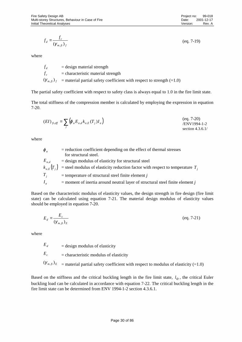
Fire Safety Design AB Project no: 99-018Multi-storey Structures, Behaviour in Case of Fire Date: 2001-12-17Initial Theoretical Analyses Version: Rev. A
Page 30 of 86
ffi,m
cd
ff
)(γ= (eq. 7-19)
where
df = design material strength
cf = characteristic material strength
ffi,m )(γ = material partial safety coefficient with respect to strength (=1.0)
The partial safety coefficient with respect to safety class is always equal to 1.0 in the fire limit state.
The total stiffness of the compression member is calculated by employing the expression in equation7-20.
( )∑=j
ajE,ad,aaeff,fi ITkEEI )()( ϕ (eq. 7-20)/ENV1994-1-2section 4.3.6.1/
where
aϕ = reduction coefficient depending on the effect of thermal stresses for structural steel.
d,aE = design modulus of elasticity for structural steel
( )jE,a Tk = steel modulus of elasticity reduction factor with respect to temperature jT
jT = temperature of structural steel finite element j
aI = moment of inertia around neutral layer of structural steel finite element j
Based on the characteristic modulus of elasticity values, the design strength in fire design (fire limitstate) can be calculated using equation 7-21. The material design modulus of elasticity valuesshould be employed in equation 7-20.
Efi,m
cd
EE
)(γ= (eq. 7-21)
where
dE = design modulus of elasticity
cE = characteristic modulus of elasticity
Efi,m )(γ = material partial safety coefficient with respect to modulus of elasticity (=1.0)
Based on the stiffness and the critical buckling length in the fire limit state, Θl , the critical Euler
buckling load can be calculated in accordance with equation 7-22. The critical buckling length in thefire limit state can be determined from ENV 1994-1-2 section 4.3.6.1.

Fire Safety Design AB Project no: 99-018Multi-storey Structures, Behaviour in Case of Fire Date: 2001-12-17Initial Theoretical Analyses Version: Rev. A
Page 31 of 86
2
2 )(
Θ
πl
EIN
eff,ficr,fi =
(eq. 7-22)/ENV1994-1-2section 4.3.6.1/
The plastic yield compression resistance (eq. 7-18) is the theoretical failure load for structures with aslenderness ratio below 1.0, whilst the Euler buckling load (eq. 7-22) applies for slenderness ratiosabove 1.0.
For design purposes, however, a design equation has been assessed which consistently keeps thedesign load below the yield compression resistance as well as the Euler buckling load. The designload is determined by applying a reduction factor, χ, on the yield compression resistance.
( ) Rd.pl,fid N.N 21χ=(eq. 7-23)/ENV1994-1-2section 4.3.6.1/
The factor χ is a function of the slenderness ratio. It can be obtained in ENV 1993-1-1 or in BSK 94(named ω in BSK 94). The constant 1.2 is a correction factor that allows for a number of effects,including the difference in the strain at failure compared to yield strain. The value is empirical.
( ) Rd.pl,fid N.N 21χ=(eq. 7-24)/ENV1993-1-1section 5.5.1.2/
The reduction factor for the relevant buckling mode is defined as
22
1
ΘλΦΦχ
−+= (eq. 7-25)
with
( )( )220150 ΘΘ λλαΦ +−+= ..
(eq. 7-26)/ENV1993-1-1Section 5.5.1.2/
The imperfection factor is taken from buckling curve c in fire
490.=α(eq. 7-27)ENV1993-1-1section 5.5.1.2
The slenderness ratio in the fire limit state is calculated according to equation (7-28).
cr,fi
Rd.pl,fi
N
N=Θλ
(eq. 7-28)ENV1994-1-2Section 4.3.6.1
Fire Safety Design AB Project no: 99-018Multi-storey Structures, Behaviour in Case of Fire Date: 2001-12-17Initial Theoretical Analyses Version: Rev. A
Page 32 of 86
8 Structural Analyses of Columns
8.1 Simulations
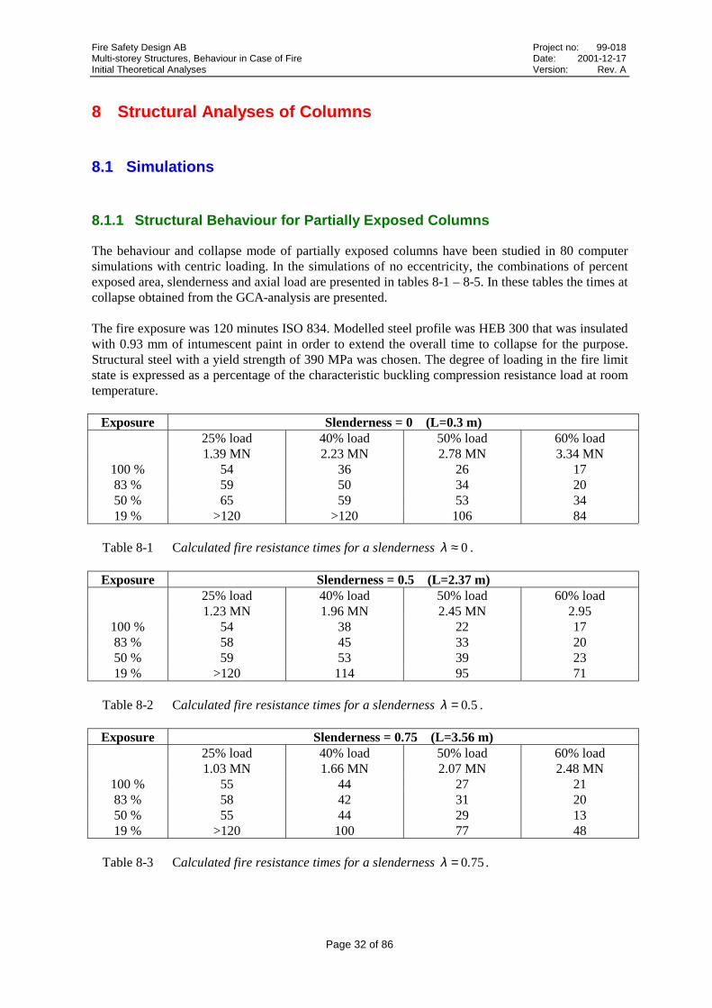
8.1.1 Structural Behaviour for Partially Exposed Columns
The behaviour and collapse mode of partially exposed columns have been studied in 80 computersimulations with centric loading. In the simulations of no eccentricity, the combinations of percentexposed area, slenderness and axial load are presented in tables 8-1 – 8-5. In these tables the times atcollapse obtained from the GCA-analysis are presented.
The fire exposure was 120 minutes ISO 834. Modelled steel profile was HEB 300 that was insulatedwith 0.93 mm of intumescent paint in order to extend the overall time to collapse for the purpose.Structural steel with a yield strength of 390 MPa was chosen. The degree of loading in the fire limitstate is expressed as a percentage of the characteristic buckling compression resistance load at roomtemperature.
Exposure Slenderness = 0 (L=0.3 m)25% load1.39 MN
40% load2.23 MN
50% load2.78 MN
60% load3.34 MN
100 % 54 36 26 1783 % 59 50 34 2050 % 65 59 53 3419 % >120 >120 106 84
Table 8-1 Calculated fire resistance times for a slenderness 0≈λ .
Exposure Slenderness = 0.5 (L=2.37 m)25% load1.23 MN
40% load1.96 MN
50% load2.45 MN
60% load2.95
100 % 54 38 22 1783 % 58 45 33 2050 % 59 53 39 2319 % >120 114 95 71
Table 8-2 Calculated fire resistance times for a slenderness 50.=λ .
Exposure Slenderness = 0.75 (L=3.56 m)25% load1.03 MN
40% load1.66 MN
50% load2.07 MN
60% load2.48 MN
100 % 55 44 27 2183 % 58 42 31 2050 % 55 44 29 1319 % >120 100 77 48
Table 8-3 Calculated fire resistance times for a slenderness 750.=λ .

Fire Safety Design AB Project no: 99-018Multi-storey Structures, Behaviour in Case of Fire Date: 2001-12-17Initial Theoretical Analyses Version: Rev. A
Page 33 of 86
Exposure Slenderness = 1.0 (L=4.74 m)25% load0.80 MN
40% load1.28 MN
50% load1.60 MN
60% load1.92 MN
100 % 57 51 41 2983 % 56 42 31 2050 % 47 35 30 819 % 118 92 65 38
Table 8-4 Calculated fire resistance times for a slenderness 01.=λ .
Exposure Slenderness = 1.5 (L=7.11 m)25% load0.45 MN
40% load0.71 MN
50% load0.89 MN
60% load1.06 MN
100 % 60 54 51 4583 % 53 41 32 2250 % 39 25 18 819 % 107 88 62 36
Table 8-5 Calculated fire resistance times for a slenderness 51.=λ .
From the tables it can be observed that minimum time for collapse occurs at about 50% of partialexposure with a slenderness exceeding 0.5. The reason for this exception is that virtually no bucklingoccurs but only axial compressive stresses arise. However, the thermal gradient causes thermalbending and an extra eccentricity for the axial load. Due to that the horizontal deformation and theeccentricity increases when exposed area decreases from 100 % to 50 %. This means that partialexposure may cause earlier collapse of the column compared with full exposure.
0
20
40
60
80
100
120
0 20 40 60 80 100
Partial Fire Exposure [%]
Co
llap
se T
ime
[m
in]
λ = 0.00 ; σ = 1.39 ΜΝλ = 0.50 ; σ = 1.23 ΜΝλ = 0.75 ; σ = 1.03 ΜΝλ = 1.00 ; σ = 0.80 ΜΝλ = 1.50 ; σ = 0.45 ΜΝ
Figure 8-1 Calculated column fire resistance times with a degree of loading of 25%.

Fire Safety Design AB Project no: 99-018Multi-storey Structures, Behaviour in Case of Fire Date: 2001-12-17Initial Theoretical Analyses Version: Rev. A
Page 34 of 86
0
20
40
60
80
100
120
0 20 40 60 80 100
Partial Fire Exposure [%]
Co
llap
se T
ime
[m
in]
λ = 0.00 ; σ = 2.23 ΜΝλ = 0.50 ; σ = 1.96 ΜΝλ = 0.75 ; σ = 1.66 ΜΝλ = 1.00 ; σ = 1.28 ΜΝλ = 1.50 ; σ = 0.71 ΜΝ
Figure 8-2 Calculated column fire resistance times with a degree of loading of 40%.
0
20
40
60
80
100
120
0 20 40 60 80 100
Partial Fire Exposure [%]
Co
llap
se T
ime
[m
in]
λ = 0.00 ; σ = 2.78 ΜΝλ = 0.50 ; σ = 2.45 ΜΝλ = 0.75 ; σ = 2.07 ΜΝλ = 1.00 ; σ = 1.60 ΜΝλ = 1.50 ; σ = 0.89 ΜΝ
Figure 8-3 Calculated column fire resistance times with a degree of loading of 50%.

Fire Safety Design AB Project no: 99-018Multi-storey Structures, Behaviour in Case of Fire Date: 2001-12-17Initial Theoretical Analyses Version: Rev. A
Page 35 of 86
0
20
40
60
80
100
120
0 20 40 60 80 100
Partial Fire Exposure [%]
Col
laps
e T
ime
[min
]λ = 0.00 ; σ = 60 %λ = 0.50 ; σ = 60 %λ = 0.75 ; σ = 60 %λ = 1.00 ; σ = 60 %λ = 1.50 ; σ = 60 %
Figure 8-4 Calculated column fire resistance times with a degree of loading of 60%.
8.1.2 Structural Behaviour of Columns with Eccentric Loads
The behaviour and collapse mode of eccentrically loaded columns have been studied in 8 computersimulations. The results in terms of collapse time are presented in table 8-6.
The fire exposure was 120 minutes ISO 834. Modelled steel profile was HEB 300 that was insulatedwith 0.93 mm of intumescent paint. Structural steel with a yield strength of 390 MPa was chosen.The degree of loading, expressed as a percentage of the design load, was set to 40%. Eccentricitiesstudied were +/- 3 cm and +/- 5 cm.
Slenderness 100% exposure, 40% loade = +5 cm e = +3 cm e = 0 e = -3 cm e = -5 cm
1.0(1.28 MN)
37 42 51 52 49
1.5(0.71 MN)
51 52 54 57 56
Table 8-6 Calculated fire resistance times for the different combinations of eccentricity andslenderness.
As expected, eccentricities adding moment in the same direction as the thermal bending, governedby the initial out-of straightness for the 100 % exposure case, resulted in shorter resistance times.With load eccentricities oriented so that a moment, acting opposite the thermal movement, is added,the resulting resistance times were longer. The -3 cm eccentricity even resulted in a minute morebefore collapse compared to the case with completely centric load.

Fire Safety Design AB Project no: 99-018Multi-storey Structures, Behaviour in Case of Fire Date: 2001-12-17Initial Theoretical Analyses Version: Rev. A
Page 36 of 86
� �� �� �� �� ��
6��
6��
�
��
��
��
��
�����#��*�
7+(�
��(#*���
8���8��������6���6���
Figure 8-5 Calculated lateral displacements for different cases of load eccentricities andslenderness 01.=λ .
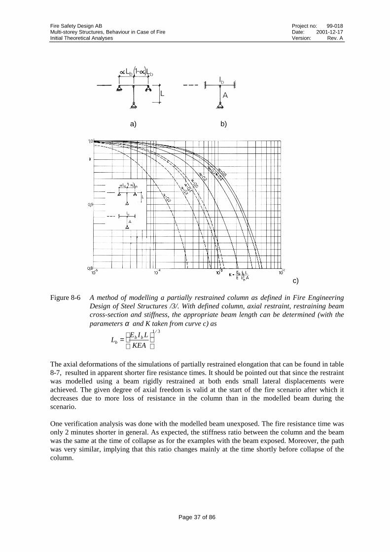
8.1.3 Columns with Partially Restrained Axial Elongation
Four complementary analyses were done to evaluate the theoretical performance of partiallyrestrained columns. The results are presented in table 8-7 and figures 8-7 – 8-8. The fire exposurewas 120 minutes of ISO 834. Modelled steel profile was HEB 300 that was insulated with 0.93 mmof intumescent paint. Structural steel with a strength of 390 MPa was chosen. The degree of loading,expressed as a percentage of the characteristic buckling compression resistance load at roomtemperature, was chosen to 40% of the of column’s capacity. The initial degree of axial freedom ofmovement was set to 80%, 90% and 100%.
The modelling of partially restrained elongation was done by connecting a beam to the top of thecolumn according to Fire Engineering Design of Steel Structures /3/ (see figure 8-6). The modelledbeam can be either exposed or unexposed. The beam was modelled as exposed in order to betterpreserve the initial conditions.
Fire Safety Design AB Project no: 99-018Multi-storey Structures, Behaviour in Case of Fire Date: 2001-12-17Initial Theoretical Analyses Version: Rev. A
Page 37 of 86
a) b)
c)
Figure 8-6 A method of modelling a partially restrained column as defined in Fire EngineeringDesign of Steel Structures /3/. With defined column, axial restraint, restraining beamcross-section and stiffness, the appropriate beam length can be determined (with theparameters α and K taken from curve c) as
31 /
bbb KEA
LIEL
=
The axial deformations of the simulations of partially restrained elongation that can be found in table8-7, resulted in apparent shorter fire resistance times. It should be pointed out that since the restraintwas modelled using a beam rigidly restrained at both ends small lateral displacements wereachieved. The given degree of axial freedom is valid at the start of the fire scenario after which itdecreases due to more loss of resistance in the column than in the modelled beam during thescenario.
One verification analysis was done with the modelled beam unexposed. The fire resistance time wasonly 2 minutes shorter in general. As expected, the stiffness ratio between the column and the beamwas the same at the time of collapse as for the examples with the beam exposed. Moreover, the pathwas very similar, implying that this ratio changes mainly at the time shortly before collapse of thecolumn.

Fire Safety Design AB Project no: 99-018Multi-storey Structures, Behaviour in Case of Fire Date: 2001-12-17Initial Theoretical Analyses Version: Rev. A
Page 38 of 86
Column Axial freedom of movement at start time
γ = 0.8 γ = 0.9 γ = 1.0
Slenderness=0.5(L=4.74)
(1.28 MN)20* 25* 38
Slenderness=1.0(L=2.37)
(1.96 MN)28* 38* 51
Table 8-7 Calculated fire resistance times for the different combinations of axial freedom ofmovement and slenderness.*True collapse not reported until later, but this time refers to the time of lost capacity.
The used restraint model involving a beam may be suited to determine the axial degree of freedom atany given time. However, the model is limited for theoretical studies of fixed partial restraint ofcolumns and it is obvious that fixed partial restraint situations would not occur in any real firescenario.
The resulting axial deformation plots for a slenderness of 1.0 and 0.5, presented in figures 8-7 – 8-8respectively, indicate what appears to be sudden structural failure of restrained columns.
� �� �� �� �� ��6�
�
�
��
��
��
��
��
��'� �'����'
Figure 8-7 Calculated axial deformations over time for initial axial degrees of freedom between80% and 100% and a slenderness 01.=λ . [minutes, mm]

Fire Safety Design AB Project no: 99-018Multi-storey Structures, Behaviour in Case of Fire Date: 2001-12-17Initial Theoretical Analyses Version: Rev. A
Page 39 of 86
� � �� �� �� �� �� �� ��6��
6�
�
�
��
��
��'� �'����'
Figure 8-8 Calculated axial deformations over time for initial axial degrees of freedom between80% and 100% and a slenderness 50.=λ . [minutes, mm]
It was concluded that the true degree of axial freedom decreases with increasing steel temperatures.Observations related to the decrease in axial freedom involve two effects in opposition to each otherin terms of performance of partly restrained columns during fire and one effect that was found to beadvantageous to the overall performance of the loadbearing system.
In one of the analyses with slenderness 0.5 the axial degree of freedom was kept at the initially set80% for 16.8 minutes exposure after which it suddenly dropped towards zero. In reality this wouldmean that the initial boundary condition at the column-beam connection changes from being almostrigid to nearly fixed before the time of column collapse. In a design situation this in turn would meanthan an exaggerated buckling length was being used in fire design, that does not correspond to theactual collapse state. The initial degree of axial freedom can not necessarily can be separated into arelevant criteria for a fire-exposed member, since its progress is determined by the structureproviding the restraint as well as the interaction between the two. Possible design criterias shouldfocus on the final degree of freedom near the fire-related collapse.
The decreasing degree of axial freedom and the resulting, near-fixed connection, at the time ofcollapse will on the other hand help generating large thermal stresses in fire that can be critical andthat are not always considered in fire design.
The third effect observed was load redistribution. During and after the sudden drop of stability of thecolumn, loads are redistributed to the modelled beam. The column almost reaches collapse statebefore all of the applied load is redistributed to the modelled beam. In order to reach true columncollapse near the time of sudden loss of loadbearing capacity it may be necessary to raise the load alittle above the capacity of the beam alone, but the resulting state of the column has to be regarded ascollapse.
The results from the analyses indicate that the disadvantageous effect of increased thermal stressmay surpass the advantageous effect of the reduced buckling length. On the other hand, the increasedrestraint does increase the degree of load redistribution to the rest of the structural system. In order
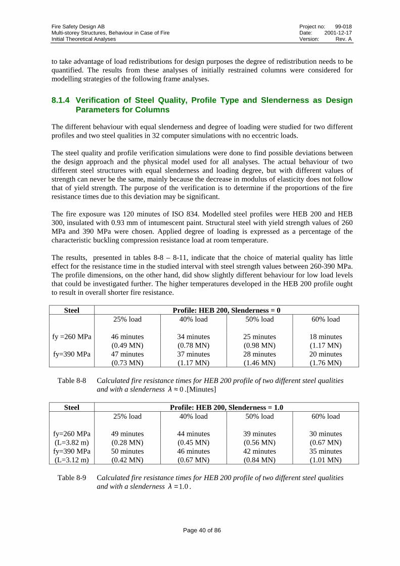
Fire Safety Design AB Project no: 99-018Multi-storey Structures, Behaviour in Case of Fire Date: 2001-12-17Initial Theoretical Analyses Version: Rev. A
Page 40 of 86
to take advantage of load redistributions for design purposes the degree of redistribution needs to bequantified. The results from these analyses of initially restrained columns were considered formodelling strategies of the following frame analyses.
8.1.4 Verification of Steel Quality, Profile Type and Slenderness as DesignParameters for Columns
The different behaviour with equal slenderness and degree of loading were studied for two differentprofiles and two steel qualities in 32 computer simulations with no eccentric loads.
The steel quality and profile verification simulations were done to find possible deviations betweenthe design approach and the physical model used for all analyses. The actual behaviour of twodifferent steel structures with equal slenderness and loading degree, but with different values ofstrength can never be the same, mainly because the decrease in modulus of elasticity does not followthat of yield strength. The purpose of the verification is to determine if the proportions of the fireresistance times due to this deviation may be significant.
The fire exposure was 120 minutes of ISO 834. Modelled steel profiles were HEB 200 and HEB300, insulated with 0.93 mm of intumescent paint. Structural steel with yield strength values of 260MPa and 390 MPa were chosen. Applied degree of loading is expressed as a percentage of thecharacteristic buckling compression resistance load at room temperature.
The results, presented in tables 8-8 – 8-11, indicate that the choice of material quality has littleeffect for the resistance time in the studied interval with steel strength values between 260-390 MPa.The profile dimensions, on the other hand, did show slightly different behaviour for low load levelsthat could be investigated further. The higher temperatures developed in the HEB 200 profile oughtto result in overall shorter fire resistance.
Steel Profile: HEB 200, Slenderness = 025% load 40% load 50% load 60% load
fy =260 MPa 46 minutes(0.49 MN)
34 minutes(0.78 MN)
25 minutes(0.98 MN)
18 minutes(1.17 MN)
fy=390 MPa 47 minutes(0.73 MN)
37 minutes(1.17 MN)
28 minutes(1.46 MN)
20 minutes(1.76 MN)
Table 8-8 Calculated fire resistance times for HEB 200 profile of two different steel qualitiesand with a slenderness 0≈λ .[Minutes]
Steel Profile: HEB 200, Slenderness = 1.025% load 40% load 50% load 60% load
fy=260 MPa(L=3.82 m)
49 minutes(0.28 MN)
44 minutes(0.45 MN)
39 minutes(0.56 MN)
30 minutes(0.67 MN)
fy=390 MPa(L=3.12 m)
50 minutes(0.42 MN)
46 minutes(0.67 MN)
42 minutes(0.84 MN)
35 minutes(1.01 MN)
Table 8-9 Calculated fire resistance times for HEB 200 profile of two different steel qualitiesand with a slenderness 01.=λ .

Fire Safety Design AB Project no: 99-018Multi-storey Structures, Behaviour in Case of Fire Date: 2001-12-17Initial Theoretical Analyses Version: Rev. A
Page 41 of 86
Steel Profile: HEB 300, Slenderness = 025% load 40% load 50% load 60% load
fy=260 MPa 53 minutes(0.93 MN)
34 minutes(1.49 MN)
25 minutes(1.86 MN)
14 minutes(2.23 MN)
fy=390 MPa 53 minutes(1.39 MN)
36 minutes(2.23 MN)
27 minutes(2.78 MN)
16 minutes(3.34 MN)
Table 8-10 Calculated fire resistance times for HEB 300 profile of two different steel qualitiesand with a slenderness 0≈λ .
Steel Profile: HEB 300, Slenderness = 1.025% load 40% load 50% load 60% load
fy=260 MPa(L=5.81 m)
56 minutes(0.53 MN)
49 minutes(0.85 MN)
37 minutes(1.07 MN)
29 minutes(1.28 MN)
fy=390 MPa(L=4.74 m)
57 minutes(0.80 MN)
51 minutes(1.28 MN)
41 minutes(1.60 MN)
32 minutes(1.92 MN)
Table 8-11 Calculated fire resistance times for HEB 300 profile of two different steel qualitiesand with a slenderness 01.=λ .
8.1.5 Verification of Applied Degree of Loading
A supplementing analysis of a previously studied column (HEB 300, fy=390 MPa, 100% exposure,slenderness=1.0) was done with loading degree increased to up to 80%. The results are compared intable 8-12.
0% load 25% load0.80 MN
40% load1.28 MN
50% load1.60 MN
60% load1.92 MN
70% load2.24 MN
80% load2.56 MN
- 57 51 41 29 24 19
Table 8-12 Calculated fire resistance times for a slenderness 01.=λ .
8.1.6 Verification of Applied Design Load and Initial Out-of-straightness
Comparisons between applied degrees of loading as a percentage of the axial design load andcorresponding maximum loads at room temperature, 20 °C, as calculated by GCA have been donefor profile HEB 300 and steel with a yield strength of 390 MPa.
The maximum load as determined by GCA, compared to the characteristic buckling compressionresistance, increases with increasing slenderness. This indicates that the slenderness dependence ofthe characteristic buckling compression resistance may be conservative at room temperature as wellas for 100% exposure as was indicated by the results in section 8.1.1, even when a non-linearsecond-order model and a non-linear material model is applied.
For studied profile and steel quality a slenderness of 0.5 the GCA and design load approach resultedin almost equal maximum loads.
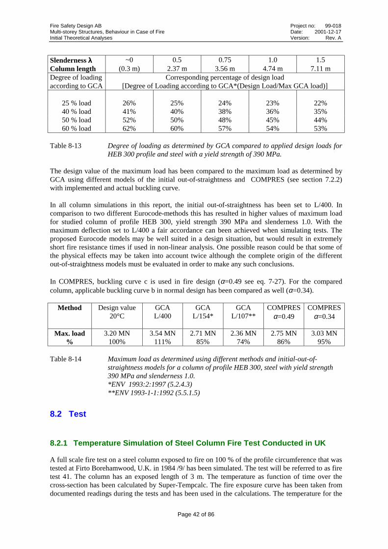
Fire Safety Design AB Project no: 99-018Multi-storey Structures, Behaviour in Case of Fire Date: 2001-12-17Initial Theoretical Analyses Version: Rev. A
Page 42 of 86
Slenderness λλλλ ~0 0.5 0.75 1.0 1.5Column length (0.3 m) 2.37 m 3.56 m 4.74 m 7.11 mDegree of loadingaccording to GCA
Corresponding percentage of design load[Degree of Loading according to GCA*(Design Load/Max GCA load)]
25 % load 26% 25% 24% 23% 22%40 % load 41% 40% 38% 36% 35%50 % load 52% 50% 48% 45% 44%60 % load 62% 60% 57% 54% 53%
Table 8-13 Degree of loading as determined by GCA compared to applied design loads forHEB 300 profile and steel with a yield strength of 390 MPa.
The design value of the maximum load has been compared to the maximum load as determined byGCA using different models of the initial out-of-straightness and COMPRES (see section 7.2.2)with implemented and actual buckling curve.
In all column simulations in this report, the initial out-of-straightness has been set to L/400. Incomparison to two different Eurocode-methods this has resulted in higher values of maximum loadfor studied column of profile HEB 300, yield strength 390 MPa and slenderness 1.0. With themaximum deflection set to L/400 a fair accordance can been achieved when simulating tests. Theproposed Eurocode models may be well suited in a design situation, but would result in extremelyshort fire resistance times if used in non-linear analysis. One possible reason could be that some ofthe physical effects may be taken into account twice although the complete origin of the differentout-of-straightness models must be evaluated in order to make any such conclusions.
In COMPRES, buckling curve c is used in fire design (α=0.49 see eq. 7-27). For the comparedcolumn, applicable buckling curve b in normal design has been compared as well (α=0.34).
Method Design value20°C
GCAL/400
GCAL/154*
GCAL/107**
COMPRESα=0.49
COMPRESα=0.34
Max. load 3.20 MN 3.54 MN 2.71 MN 2.36 MN 2.75 MN 3.03 MN% 100% 111% 85% 74% 86% 95%
Table 8-14 Maximum load as determined using different methods and initial-out-of-straightness models for a column of profile HEB 300, steel with yield strength390 MPa and slenderness 1.0.*ENV 1993:2:1997 (5.2.4.3)**ENV 1993-1-1:1992 (5.5.1.5)
8.2 Test
8.2.1 Temperature Simulation of Steel Column Fire Test Conducted in UK
A full scale fire test on a steel column exposed to fire on 100 % of the profile circumference that wastested at Firto Borehamwood, U.K. in 1984 /9/ has been simulated. The test will be referred to as firetest 41. The column has an exposed length of 3 m. The temperature as function of time over thecross-section has been calculated by Super-Tempcalc. The fire exposure curve has been taken fromdocumented readings during the tests and has been used in the calculations. The temperature for the

Fire Safety Design AB Project no: 99-018Multi-storey Structures, Behaviour in Case of Fire Date: 2001-12-17Initial Theoretical Analyses Version: Rev. A
Page 43 of 86
100 % exposure is presented in figure 7-8 where measured and computed temperatures are comparedfor the exposed web and unexposed flange respectively. The agreement between calculated andmeasured temperatures is considered adequate.
Figure 8-9 Description of fire test 41 on steel column (h*w*tw*tf =206x204x8x12.5 mm) fully fireexposed /3/
� � �� �� �� �� ��
���
���
���
���
���
���
���
���� �#��*�
��� ������
°���
Figure 8-10 Comparison of predicted and measured temperature of fire exposed steel column(w*h*tw*tf =204x206x12.5x8 mm) web for fire test 41 under 100 % fire exposure.(Dashed line = measured, solid line = predicted)
The tested steel column has an effective length of 2.1 m (fully exposed). The slenderness ratio is0.45 (weak axis) and 0.24 (strong axis) respectively i.e. a short column with almost no bucklinginfluence. The deformation behaviour and the collapse time for the fire tested column (100% fire

Fire Safety Design AB Project no: 99-018Multi-storey Structures, Behaviour in Case of Fire Date: 2001-12-17Initial Theoretical Analyses Version: Rev. A
Page 44 of 86
exposure and 60% of allowed maximum load according to test standard) has been predicted byGlobal Collapse Analysis and compared with measured results.
The measured value of steel strength was 349 MPa, to be compared with the design value of 255MPa. The actual degree of loading is therefore less than the allowed 60%. The actual, measuredvalue of strength was used in the simulations. The modulus of elasticity modulus was set to 210 GPasince it was not measured during the test.
In figure 8-11 the predicted and measured axial deformation as function of time is compared. Theconcordance in deformation process is good and the collapse time is predicted to 19 minutescompared to the measured 23 minutes. Due to all testing uncertainties and the normal variation ofresults (sometimes up to 50% for columns) from fire testing on identical specimens this difference isquite acceptable.
� � �� �� �� ��
6�
�
�
��
��
��
��
�����#��*�
9���� ��)+(�
��(#���
: *��)�1�)���)
Figure 8-11 Measured axial deformations of column (fire test 41) compared to predicted.(Dotted line = measured, solid line = predicted)
A comparison was done with the column analysed using the tool COMPRES. With a measuredinitial value of steel strength the resistance time was determined to 22 minutes. For furthercomparisons the design value of steel strength resulted in a resistance time of 19 minutes. The designvalue is of little importance here since given another sample, the measured strength could be close tothe design value.
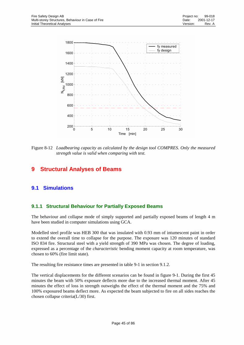
Fire Safety Design AB Project no: 99-018Multi-storey Structures, Behaviour in Case of Fire Date: 2001-12-17Initial Theoretical Analyses Version: Rev. A
Page 45 of 86
� � �� �� �� �� �����
���
���
���
����
����
����
����
����
;+�-!)�����;�
�������#�
+�� *��)+��)*�$#��
Figure 8-12 Loadbearing capacity as calculated by the design tool COMPRES. Only the measuredstrength value is valid when comparing with test.
9 Structural Analyses of Beams
9.1 Simulations
9.1.1 Structural Behaviour for Partially Exposed Beams
The behaviour and collapse mode of simply supported and partially exposed beams of length 4 mhave been studied in computer simulations using GCA.
Modelled steel profile was HEB 300 that was insulated with 0.93 mm of intumescent paint in orderto extend the overall time to collapse for the purpose. The exposure was 120 minutes of standardISO 834 fire. Structural steel with a yield strength of 390 MPa was chosen. The degree of loading,expressed as a percentage of the characteristic bending moment capacity at room temperature, waschosen to 60% (fire limit state).
The resulting fire resistance times are presented in table 9-1 in section 9.1.2.
The vertical displacements for the different scenarios can be found in figure 9-1. During the first 45minutes the beam with 50% exposure deflects more due to the increased thermal moment. After 45minutes the effect of loss in strength outweighs the effect of the thermal moment and the 75% and100% exposured beams deflect more. As expected the beam subjected to fire on all sides reaches thechosen collapse criteria(L/30) first.

Fire Safety Design AB Project no: 99-018Multi-storey Structures, Behaviour in Case of Fire Date: 2001-12-17Initial Theoretical Analyses Version: Rev. A
Page 46 of 86
� �� �� �� �� �� �� �� �� �6���
6���
6���
6���
6��
�
��'���'���'����'
Figure 9-1 Vertical displacements at centre of span of beam HEB 300 subjected to exposurebetween 25-100% of the circumference.
9.1.2 Verification of Applied Design Load
Applied degrees of loading as percentage of the characteristic bending moment capacity at roomtemperature 20 °C have been verified according to Eurocode 3 /1/, using the tool SBEAM (seesection 7.2.1). The fire resistance time comparisons are presented in table 9-1.
Since SBEAM considers the bending moment capacity only and not deflections and since the entirecross-section is allowed to reach yield, the small difference is not easy to explain. The fire resistancetime for the fully exposed circumference was even 1 minute shorter with SBEAM. The thermalmoment is what prevents similar deviations for the simulations with the beam partially exposed.
Beam HEB 300, fy=390 MPa, Load =60%, L=4 mExposure 100% 83% 50% 19%
GCA 55 minutes 59 minutes 64 minutes >>120 minutesSBEAM 54 minutes 60 minutes 64 minutes >>120 minutes
Table 9-1 Calculated fire resistance times for partially exposed beams. [minutes]
In order to verify a possible reason for the similar results using the different methods, the GCA-calculated cross-sectional stress distribution at mid-span and L/4-span is presented in figure 9-2 for100% fire exposure at 3 different times. By studying the cross-sectional stress development in figure9-2 it turns out that while beyond the proportional limit, no point has reached yield stress within thetime set by the collapse criteria (L/30). This may be important since the cross-sectional designsimplification assumes full yield in the entire cross-section at displacements that are only beyond theproportional limit (see figure 9-3).
Time [minutes]
[mm]

Fire Safety Design AB Project no: 99-018Multi-storey Structures, Behaviour in Case of Fire Date: 2001-12-17Initial Theoretical Analyses Version: Rev. A
Page 47 of 86
Cross-sectional stress distributionat x=L/2 (2 m)
6��� 6��� 6��� � ��� ��� ����
����
���
����
���
����
���,�#����%�&�����:�#��*��������
��1 �
0 minutes
Cross-sectional stress distributionat x=L/4 (1 m)
6��� 6��� 6��� � ��� ��� ����
����
���
����
���
����
���,�#���%�&�����:�#��*��������
��1 �
0 minutes
6��� 6��� 6��� � ��� ��� ����
����
���
����
���
����
���,�#����%�&��� ��:�#��*��������
��1 �
29 minutes
6��� 6��� 6��� � ��� ��� ����
����
���
����
���
����
���,�#���%�&��� ��:�#��*��������
��1 �
29 minutes
6��� 6��� 6��� � ��� ��� ����
����
���
����
���
����
���,�#����%�&������:�#��*��������
��1 �
55 minutes
6��� 6��� 6��� � ��� ��� ����
����
���
����
���
����
���,�#���%�&������:�#��*��������
��1 �
55 minutes
Figure 9-2 Cross-sectional stress-distribution(solid line) at x=L/2 and x=L/4 as calculated byGCA for the simulation with 100% exposure. Proportional limit: dash-dotted. Yieldlimit:dashed.

Fire Safety Design AB Project no: 99-018Multi-storey Structures, Behaviour in Case of Fire Date: 2001-12-17Initial Theoretical Analyses Version: Rev. A
Page 48 of 86
Figure 9-3 The moment as function of displacement. The dashed line represents the usualsimplifictaion in design. Displacements beyond the proportional limit, but prior to theyield limit will be treated as fully yielded in a design situation at cross-sectional level.
Finally the moment distribution over the beam length is shown in figure 9-5. At the time of thedisplacement-governed collapse, the moment capacity criteria is fulfilled.
� ��� � ��� � ��� � ��� �6���
6���
6���
6���
6���
6���
6���
6���
6��
�
<�)�*� #����
:(#����;�
55 minutes
Figure 9-4 The moment in the beam length direction as calculated by GCA for the simulation with100% exposure. Applied load q=209.4 kN/m resulted in a maximum moment 418.8kNm that is constant throughout the scenario. The moment calculated as qL2/8 is 419.5kNm. The GCA error is +1.67%, which is not much considering the complex iterationprocedure and the number of iterations.
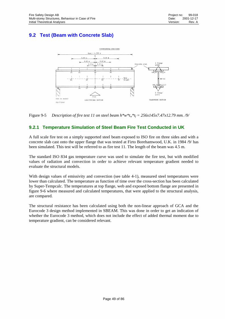
Fire Safety Design AB Project no: 99-018Multi-storey Structures, Behaviour in Case of Fire Date: 2001-12-17Initial Theoretical Analyses Version: Rev. A
Page 49 of 86
9.2 Test (Beam with Concrete Slab)
Figure 9-5 Description of fire test 11 on steel beam h*w*tw*tf = 256x145x7.47x12.79 mm. /9/
9.2.1 Temperature Simulation of Steel Beam Fire Test Conducted in UK
A full scale fire test on a simply supported steel beam exposed to ISO fire on three sides and with aconcrete slab cast onto the upper flange that was tested at Firto Borehamwood, U.K. in 1984 /9/ hasbeen simulated. This test will be referred to as fire test 11. The length of the beam was 4.5 m.
The standard ISO 834 gas temperature curve was used to simulate the fire test, but with modifiedvalues of radiation and convection in order to achieve relevant temperature gradient needed toevaluate the structural models.
With design values of emissivity and convection (see table 4-1), measured steel temperatures werelower than calculated. The temperature as function of time over the cross-section has been calculatedby Super-Tempcalc. The temperatures at top flange, web and exposed bottom flange are presented infigure 9-6 where measured and calculated temperatures, that were applied to the structural analysis,are compared.
The structural resistance has been calculated using both the non-linear approach of GCA and theEurocode 3 design method implemented in SBEAM. This was done in order to get an indication ofwhether the Eurocode 3 method, which does not include the effect of added thermal moment due totemperature gradient, can be considered relevant.

Fire Safety Design AB Project no: 99-018Multi-storey Structures, Behaviour in Case of Fire Date: 2001-12-17Initial Theoretical Analyses Version: Rev. A
Page 50 of 86
� � �� �� �� �� ���
���
���
���
���
���
���
�����#��*�
��� ������ °�
��
Top flange
� � �� �� �� �� ���
���
���
���
���
���
���
���
���
��
�����#��*�
��� ������ °�
��
Web
� � �� �� �� �� ���
���
���
���
���
���
���
���
���
�����#��*�
��� ������ °�
��
Bottom flange
Figure 9-6 Comparison of measured and calculated temperature of fire exposed steel beam(h*w*tweb*tflange = 256x145x7.47x12.79 mm) for fire test 11 with the exposureaccording to figure 9-2. (Dashed line = measured, solid line = predicted/applied)
A maximum allowed deflection of L/30 was used as stability criteria. With a span of 4.5 m thismeans a maximum deflection of 150 mm. A comparison of measured deflections and deflections ascalculated with GCA is presented in figure 9-7. The fire resistance of the tested beam was 22minutes and corresponding GCA calculation resulted in 19.6 minutes of fire resistance.

Fire Safety Design AB Project no: 99-018Multi-storey Structures, Behaviour in Case of Fire Date: 2001-12-17Initial Theoretical Analyses Version: Rev. A
Page 51 of 86
� � �� �� ���
��
��
��
��
���
���
���
���
�����#��*�
9���� ��)+����(#� ���)6*� #���
*��)���)���)
4����
Figure 9-7 Deflections at centre of beam. The collapse time of the GCA simulation was 19.6minutes. The resistance time of the test was 21.7 minutes.
A comparison to design with the tool SBEAM is shown in figure 9-8. The SBEAM calculation, thatdoes not consider deflections, resulted in 20.8 minutes of structural stability during fire. Thiscorresponds to the time when the load bearing capacity reached the value of the load effect of 80kNm.
� � �� �� �� �� ����
��
��
��
���
���
���
���
���
:� ������;�
�������#�
Figure 9-8 Moment capacity as calculated using SBEAM. The fire resistance time was 20.8minutes, to be compared with 21.7 minutes of the test.
The deviation between measured results, simulations and the Eurocode 3 design method is too smallto conclude that the effect of the thermal moment would be significant for beams in general.

Fire Safety Design AB Project no: 99-018Multi-storey Structures, Behaviour in Case of Fire Date: 2001-12-17Initial Theoretical Analyses Version: Rev. A
Page 52 of 86
9.3 Continuous beams
A statically indeterminate beam (continuous beam) has a greater load bearing capacity compared to afreely supported beam. The reason for this is transfer of bending moment between support and spanwhen the continuous beam is approaching its ultimate strength capacity. Calculations according tothe theory of elasticity does not consider this and will therefore not give the optimal result as regardsthe load bearing capacity. Another method is the theory of plasticity where yield points areintroduced in critical sections of the continuous beam. The number of yield points depends on thedegree of statically indeterminacy. See figure 9-9.
a) b)
Figure 9-9 Moment distribution for a statically indeterminate beam according toa) theory of elasticityb) theory of plasticityMp is the yield point moment. /11/.
Figure 9-10 shows an example of a continuous beam with different load combinations. Dependingon the location of the free loads, different load bearing ratios considering support and span are beingderived.
Figure 9-10 Example of a continuous beam with different load combinations. Depending on thelocation of the free loads, different load bearing ratios considering support andspan will be derived. Each span has a length of L.
In order to determine the ultimate moment (yielding moment) of the beam before collapse thecontinuous beam in figure 9-10 is divided into two load cases. See figure 9-11.

Fire Safety Design AB Project no: 99-018Multi-storey Structures, Behaviour in Case of Fire Date: 2001-12-17Initial Theoretical Analyses Version: Rev. A
Page 53 of 86
a) b)
Figure 9-11 Moment distribution for a statically indeterminate beam, according toa) theory of elasticityb) theory of plasticity /11/
In order to maintain equilibrium of moments, the moment in the yield points are the same. Therelationship between the theory of elasticity and the theory of plasticity gives the modified loadbearing capacity in the fire limit state according to figure 9-12.
Figure 9-12 Modifying factors of the load bearing capacity in the fire limit state for acontinuous beam with distributed load. Explanation:
support.at
elasticityoftheorythetoaccordingcapacitybearingloadmodified
support.at
asticityploftheorythetoaccordingcapacitybearingloadmodified
portsupelast
portsupitlim
=
=
µ
µ
The theory of plasticity considers transfer of bending moment between support and span at roomtemperature. At 20 °C yield points appear suddenly as the stress-related strain reaches theproportional limit, which is equal to the yield limit. At higher temperatures, the yield limit is reachedafter the proportional limit and the corresponding loss of strength is progressive. This might indicatethat a moment redistribution as given by the theory of plasticity at room temperature would be validin fire, provided loads start to take other paths as soon as one section becomes weaker than others.
A statically indeterminate beam was analysed using GCA in order to verify the theory of plasticity infire. The beam is shown figure 9-13.
Case 1(end span)
Case 2(middle span)
680.portsupelast
portsupitlim ⋅= µµ
750.portsupelast
portsupitlim ⋅= µµ
Case 1(end span)
Case 2(middle span)

Fire Safety Design AB Project no: 99-018Multi-storey Structures, Behaviour in Case of Fire Date: 2001-12-17Initial Theoretical Analyses Version: Rev. A
Page 54 of 86
Figure 9-13 Continuous steel beam modelled for non-linear analysis.
The maximum cross-sectional bending moment capacity is 698.2 kNm.
The allowed moment according to the theory of elasticity becomes:
349,1 kN/m (698.2 = qd*42/8).
The allowed moment according to the theory of plasticity becomes:
510,6 kN/m (698.2 = qd*42/11.7).
In the analysis a uniformly distributed load of q=320 kN/m was applied as shown in figure 9-13.
Corresponding maximum moment of applied load is:
M = 320*42/8 = 640 kNm according to the theory of elasticity (92% load utilisation)M = 320*42/11.7 = 438 kNm according to the theory of plasticity (63% load utilisation)
A simple cross-sectional analysis as performed with SBEAM gives a fire resistance time of:
42 minutes according with loading degree determined according to the theory of elasticity53 minutes according with loading degree determined according to the theory of plasticity
� �� �� �� �� ��� ����
���
���
���
���
���
���
���
:� ������;�
�������#�
Figure 9-14 Moment capacity over time as determined by SBEAM calculation.Solid line: moment according to theory of elasticityDashed line: moment according to theory of plasticity
Steel beam HEB 300Steel of strength 390 MPa4-side exposureInsulated with intumescent paint

Fire Safety Design AB Project no: 99-018Multi-storey Structures, Behaviour in Case of Fire Date: 2001-12-17Initial Theoretical Analyses Version: Rev. A
Page 55 of 86
The resistance time as given by the non-linear analysis was 58 minutes. The deflection at center ofone span is shown in figure 9-15.
� �� �� �� �� ��
6���
6���
6���
6���
6��
6��
6��
6��
�;()��������7�����(#�����������
�6���
4����
Figure 9-15 Deflection at center of one span of analysed continous beam.
The moment distribution after 0 and 27.4 minutes are shown in figure 9-16.
At the start, after loads have been applied, the moment at the center support was determined to 628kNm which should be compared to 640 kNm accrding to the theory of elasticity. At any of the centerspans the moment was 365 kNm, compared to 358 kNm accoording to theory of elasticity.
After 27 minutes moment redistribution results in equal moment at support and in center span, 439kNm, which can be compared to 438 kNm as given by the theory of plasticity.
� � � � � � � � �
6���
6���
6���
�
���
���
���
Figure 9-16 The moment distribution after 0 minutes (solid) and 27.4 minutes(dashed).

Fire Safety Design AB Project no: 99-018Multi-storey Structures, Behaviour in Case of Fire Date: 2001-12-17Initial Theoretical Analyses Version: Rev. A
Page 56 of 86
The cross-sectional distribution of stress and E-modulus (solid line curves) at time of failure areshown in figures 9-17 – 9-19 for sections at end support, center span and center support. The loss ofstiffness is greatest at the center support, which may explain why load redistributions from thatsection started early. There is an indication, although it can not be fully concluded, that loadredistributions begin as soon as loss of strength and stiffness starts to develop in any section.
6��� 6��� 6��� � ��� ��� ����
����
���
����
���
����
���,�#���%�&���������:�#��*��������
��1 �
� �� ��� ��� ����
����
���
����
���
����
���,�#���%�&��������:�#��*��������
�1 �
a) stress (solid line) b) E-modulus (solid line)
Figure 9-17 The cross-sectional stress and E-modulus at end support at time of failure, after 58minutes of fire exposure.
6��� 6��� 6��� � ��� ��� ����
����
���
����
���
����
���,�#�� %�&���������:�#��*��������
��1 �
� �� ��� ��� ����
����
���
����
���
����
���,�#�� %�&��������:�#��*��������
�1 �
a) stress b) E-modulus
Figure 9-18 The cross-sectional stress and E-modulus at center span at time of failure, after 58minutes of fire exposure.
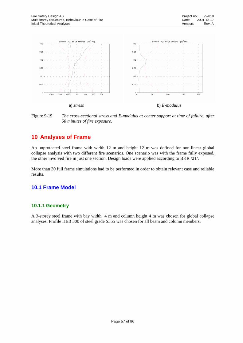
Fire Safety Design AB Project no: 99-018Multi-storey Structures, Behaviour in Case of Fire Date: 2001-12-17Initial Theoretical Analyses Version: Rev. A
Page 57 of 86
6��� 6��� 6��� � ��� ��� ����
����
���
����
���
����
���,�#����%�&���������:�#��*��������
��1 �
� �� ��� ��� ����
����
���
����
���
����
���,�#����%�&��������:�#��*��������
�1 �
a) stress b) E-modulus
Figure 9-19 The cross-sectional stress and E-modulus at center support at time of failure, after58 minutes of fire exposure.
10 Analyses of Frame
An unprotected steel frame with width 12 m and height 12 m was defined for non-linear globalcollapse analysis with two different fire scenarios. One scenario was with the frame fully exposed,the other involved fire in just one section. Design loads were applied according to BKR /21/.
More than 30 full frame simulations had to be performed in order to obtain relevant case and reliableresults.
10.1 Frame Model
10.1.1 Geometry
A 3-storey steel frame with bay width 4 m and column height 4 m was chosen for global collapseanalyses. Profile HEB 300 of steel grade S355 was chosen for all beam and column members.

Fire Safety Design AB Project no: 99-018Multi-storey Structures, Behaviour in Case of Fire Date: 2001-12-17Initial Theoretical Analyses Version: Rev. A
Page 58 of 86
[m]
[m]
Figure 10-1 Geometry of studied frame.
The frames were initially deformed according to the first eigenmode with maximum deflection dueto initial out of straightness fixed to 10 mm (LMax/400). A magnification of the initially deformedstructure is shown in figure 10-2. With symmetrical structural properties and loading situation, thisorientation of the mode will force the collapse to the left.
The initial out-of-straightness is modelled as a modification of the global co-ordinates and nottreated as deformations.
� � � � � �� ���
�
�
�
�
��
��
Figure 10-2 100 x magnification of initial out-of straightness as determined by a maximumdeflection of 10 mm and the first eigenmode. With symmetrically applied vertical loadsthe collapse of the frame will be forced to left.
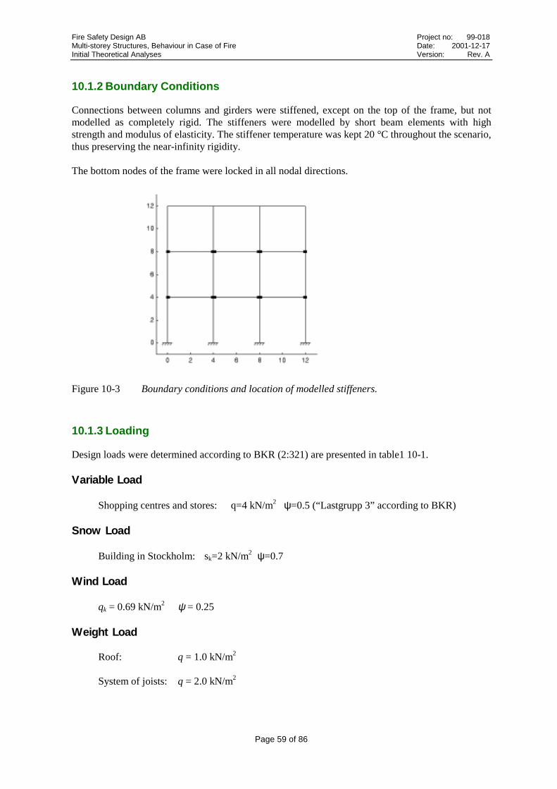
Fire Safety Design AB Project no: 99-018Multi-storey Structures, Behaviour in Case of Fire Date: 2001-12-17Initial Theoretical Analyses Version: Rev. A
Page 59 of 86
10.1.2 Boundary Conditions
Connections between columns and girders were stiffened, except on the top of the frame, but notmodelled as completely rigid. The stiffeners were modelled by short beam elements with highstrength and modulus of elasticity. The stiffener temperature was kept 20 °C throughout the scenario,thus preserving the near-infinity rigidity.
The bottom nodes of the frame were locked in all nodal directions.
Figure 10-3 Boundary conditions and location of modelled stiffeners.
10.1.3 Loading
Design loads were determined according to BKR (2:321) are presented in table1 10-1.
Variable Load
Shopping centres and stores: q=4 kN/m2 ψ=0.5 (“Lastgrupp 3” according to BKR)
Snow Load
Building in Stockholm: sk=2 kN/m2 ψ=0.7
Wind Load
qk = 0.69 kN/m2 ψ = 0.25
Weight Load
Roof: q = 1.0 kN/m2
System of joists: q = 2.0 kN/m2

Fire Safety Design AB Project no: 99-018Multi-storey Structures, Behaviour in Case of Fire Date: 2001-12-17Initial Theoretical Analyses Version: Rev. A
Page 60 of 86
Normal state limit (LK 1) Fire state limit (LK 7)
=HLsnowq 10.4 kN/m2
=VLsnowq 5.6 kN/m2 =snowq 5.6 kN/m2
Roof
=roofq 4.0 kN/m2 =roofq 4.0 kN/m2
System of joists =HLNLq 20.8 kN/m2 =NLq 8.0 kN/m2
=slabq 8.0 kN/m2 =slabq 8.0 kN/m2
Wind =HLwindq 3.6 kN/m2 =windq 0
=VLwindq 0.69 kN/m2
Table 10-1 Design load according to BKR..
Distributed load on top level was set to 9.6 kN/m. For all other beams the modelled load was 16kN/m. Loads applied in the model are illustrated in figure 10-4.
Figure 10-4 Applied loads in the frame model. q1 = 9.6 kN/m. q2 = q3 = 16 kN/m.
10.1.4 Fire Exposure
Two exposure conditions were studied. In the first case, the unprotected frame was completelyexposed to standard ISO 834 fire. The scenario of fully exposed frame was chosen to obtain anestimation of the overall performance of the frame.
In the second chosen scenario, only the centre section of the unexposed frame was exposed. Thisscenario was chosen to simulate local fire in a single fire compartmentation and to study thedevelopment of load redistribution, even without steel-concrete interaction, as exposed structuralmembers or unexposed members subjected to high thermal stresses lose strength.

Fire Safety Design AB Project no: 99-018Multi-storey Structures, Behaviour in Case of Fire Date: 2001-12-17Initial Theoretical Analyses Version: Rev. A
Page 61 of 86
Figure 10-5 The studied fire scenarios for full frame analyses.
10.2 Fully Fire-Exposed Frame
For the fully exposed frame analysis the structure was divided into 159 Bernoulli beam elements.Each member in turn was divided into 29 cross-sectional elements for each beam element node. Thus9.540 cross-sectional points per timestep and iteration were used for the incremental calculation ofeach of the properties stress, strain, etc. With a time domain division of 121 steps the number ofstored points becomes 1.154.340 per physical property or 5.771.700 totally. It is obvious that thenecessary cross-sectional division is the single most important issue for the limit of performance.The double non-linearity with geometrical second order iterations performed within the stressiteration loop is the second most important issue, since a full matrix eigenvalue analysis is performedwithin each such iteration. The main system equation is solved with sparse matrices and is not aperformance issue as such.
The finite element model of the analyzed frame is shown in figure 10-5. Individually studiedelements are denoted E#. Individually studied nodes are denoted N#.
Loads and boundary conditions were applied according to section 10.1. Distributed loads on toplevel were set to 9.6 kN/m and for all other beams the modelled distributed load was 16 kN/m.
fire
fire fire fire
fire fire fire
fire fire fire
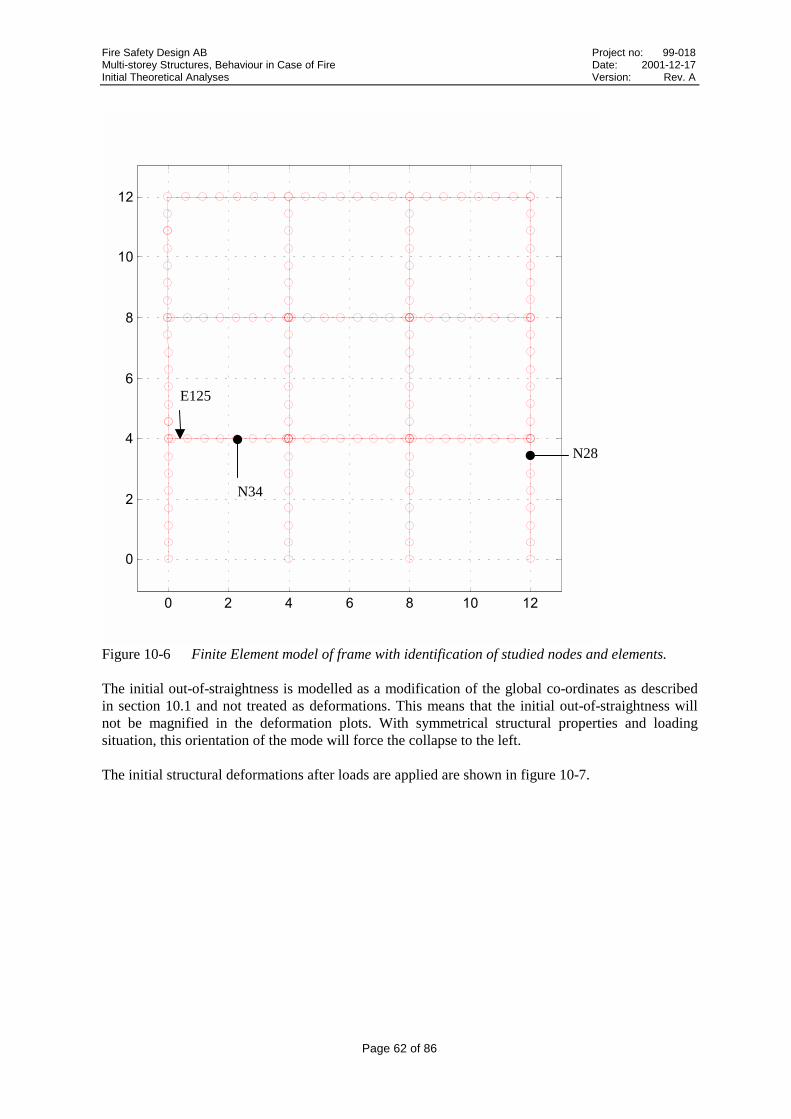
Fire Safety Design AB Project no: 99-018Multi-storey Structures, Behaviour in Case of Fire Date: 2001-12-17Initial Theoretical Analyses Version: Rev. A
Page 62 of 86
� � � � � �� ��
�
�
�
�
�
��
��
Figure 10-6 Finite Element model of frame with identification of studied nodes and elements.
The initial out-of-straightness is modelled as a modification of the global co-ordinates as describedin section 10.1 and not treated as deformations. This means that the initial out-of-straightness willnot be magnified in the deformation plots. With symmetrical structural properties and loadingsituation, this orientation of the mode will force the collapse to the left.
The initial structural deformations after loads are applied are shown in figure 10-7.
N34
E125
N28

Fire Safety Design AB Project no: 99-018Multi-storey Structures, Behaviour in Case of Fire Date: 2001-12-17Initial Theoretical Analyses Version: Rev. A
Page 63 of 86
� � � � � �� ��
�
�
�
�
�
��
��
���#��*��: $#�+�� ��(#�����3�
Figure 10-7 Deformations with loads applied at start of fire scenario. (Magnification 1000 x).
The thermal strains forces the fire-exposed frame to expand until sudden loss of strength occursshortly before the time of collapse. After 28 minutes global collapse occurs with failure of theleftmost beam (Element #125) above the first floor and the carrying column below it which has beendisplaced by the thermal expansion of the beam.
6� 6� � � � � � �� �� ��
�
�
�
�
�
��
��
��
��
�������#��*��: $#�+�� ��(#���3�
6� 6� � � � � � �� �� ��
�
�
�
�
�
��
��
��
��
��� ���#��*��: $#�+�� ��(#���3�
Figure 10-8 Deformed frame during collapse after 28-29 minutes of fire exposure. Globalcollapse starts with failure of Element #125. (Magnification 30 x)

Fire Safety Design AB Project no: 99-018Multi-storey Structures, Behaviour in Case of Fire Date: 2001-12-17Initial Theoretical Analyses Version: Rev. A
Page 64 of 86
Vertical deformations over time are shown in figure 10-9 for Node #34, which is the node nearestthe centre of the critical beam. It should be pointed out that actual, absolute deformations in onepoint are affected by the complete behaviour of the global structure.
� � �� �� �� ���
�
��
��
��
��
��
��
��
�����#��*�
7+(�
��(#*���
Figure 10-9 Vertical deformations for Node #34.
The displacements of Node #28, in the rightmost lower span column, confirms a uniform collapsebehaviour of the fully exposed frame.
� � �� �� �� �� ���
��
��
��
��
��
�����#��*�
7+(�
��(#*���
Figure 10-10 Horizontal displacements over time for Node #28.
Cross-sectional stress distribution in Element #125 is presented in figure 10-11. As expected, thebeam section has not reached fully yield condition at the time of collapse.

Fire Safety Design AB Project no: 99-018Multi-storey Structures, Behaviour in Case of Fire Date: 2001-12-17Initial Theoretical Analyses Version: Rev. A
Page 65 of 86
6�� 6�� 6�� 6�� 6�� � �� �� �� �� ���
����
���
����
���
����
���,�#�����%�&����� ���:�#��*��������
��1 �
Figure 10-11 Cross-sectional stress distribution in Element #125. The temperature-dependentproportional and yield limits are marked as dashed.
10.3 Single-Compartmentation Fire Exposure
The modelled frame fire exposure in a single fire compartmentation was divided into 138 Bernoullibeam elements. The finite element mesh of the structure is shown in figure 10-12.
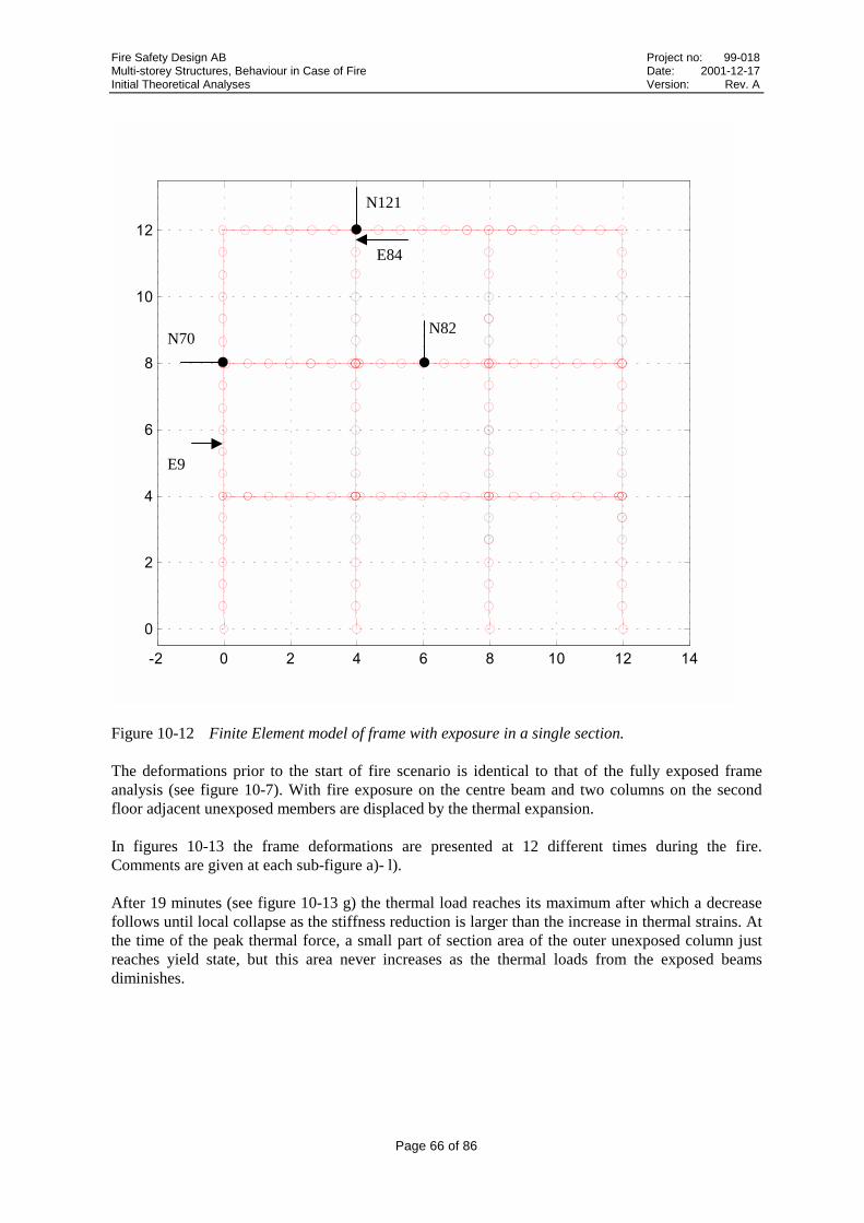
Fire Safety Design AB Project no: 99-018Multi-storey Structures, Behaviour in Case of Fire Date: 2001-12-17Initial Theoretical Analyses Version: Rev. A
Page 66 of 86
6� � � � � � �� �� ��
�
�
�
�
�
��
��
Figure 10-12 Finite Element model of frame with exposure in a single section.
The deformations prior to the start of fire scenario is identical to that of the fully exposed frameanalysis (see figure 10-7). With fire exposure on the centre beam and two columns on the secondfloor adjacent unexposed members are displaced by the thermal expansion.
In figures 10-13 the frame deformations are presented at 12 different times during the fire.Comments are given at each sub-figure a)- l).
After 19 minutes (see figure 10-13 g) the thermal load reaches its maximum after which a decreasefollows until local collapse as the stiffness reduction is larger than the increase in thermal strains. Atthe time of the peak thermal force, a small part of section area of the outer unexposed column justreaches yield state, but this area never increases as the thermal loads from the exposed beamsdiminishes.
N70
E9
N121
N82
E84

Fire Safety Design AB Project no: 99-018Multi-storey Structures, Behaviour in Case of Fire Date: 2001-12-17Initial Theoretical Analyses Version: Rev. A
Page 67 of 86
6� � � � � � �� �� ��
�
�
�
�
�
��
��
�� ���#��*��: $#�+�� ��(#���3�
6� � � � � � �� �� ��
�
�
�
�
�
��
��
�������#��*��: $#�+�� ��(#���3�
a) 4.98 minutes. The thermal expansion exceeds theeffect of the applied load.
b) 10.02 minutes. Deformation of outer unexposedmembers from thermal loads of exposed members.
6� � � � � � �� �� ��
�
�
�
�
�
��
��
����#��*��: $#�+�� ��(#���3�
6� � � � � � �� �� ��
�
�
�
�
�
��
��
�������#��*��: $#�+�� ��(#���3�
c) 15 minutes. d) 17.52 minutes. Exposed beam has lost enough stiffness for theapplied load to balance the vertical, thermal movement of the beam.
6� � � � � � �� �� ��
�
�
�
�
�
��
��
����#��*��: $#�+�� ��(#���3�
6� � � � � � �� �� ��
�
�
�
�
�
��
��
�������#��*��: $#�+�� ��(#���3�
e) 18 minutes. The deformation of exposed beam istaking the shape of the collapse mode.
f) 18.48 minutes.All exposed members near collapse.Large thermal forces on unexposed members.
Figure 10-13 Frame deformations before, during and after local collapse.

Fire Safety Design AB Project no: 99-018Multi-storey Structures, Behaviour in Case of Fire Date: 2001-12-17Initial Theoretical Analyses Version: Rev. A
Page 68 of 86
6� � � � � � �� �� ��
�
�
�
�
�
��
��
� �����#��*��: $#�+�� ��(#���3�
6� � � � � � �� �� ��
�
�
�
�
�
��
��
� ����#��*��: $#�+�� ��(#���3�
g) 19.02 minutes. Near critical state for outerunexposed columns.
h) 19.5 minutes. Still near critical state forunexposed columns as load redistribution to
unexposed members increases.
6� � � � � � �� �� ��
�
�
�
�
�
��
��
�������#��*��: $#�+�� ��(#���3�
6� � � � � � �� �� ��
�
�
�
�
�
��
��
�������#��*��: $#�+�� ��(#���3�
i) 22.02 minutes. Collapse of all exposed membersbegins.
j) 23.52 minutes. Less deformations of unexposedupper beams with decrease in thermal forces.
6� � � � � � �� �� ��
�
�
�
�
�
��
��
����#��*��: $#�+�� ��(#���3�
6� � � � � � �� �� ��
�
�
�
�
�
��
��
�������#��*��: $#�+�� ��(#���3�
i) 24 minutes. j) 24.48 minutes.

Fire Safety Design AB Project no: 99-018Multi-storey Structures, Behaviour in Case of Fire Date: 2001-12-17Initial Theoretical Analyses Version: Rev. A
Page 69 of 86
6� � � � � � �� �� ��
�
�
�
�
�
��
��
��� ���#��*��: $#�+�� ��(#���3�
6� � � � � � �� �� ��
�
�
�
�
�
��
��
����#��*��: $#�+�� ��(#���3�
k) 34.98 minutes. Stable condition. l) 60 minutes. Stable condition.
Figure 10-13 Frame deformations before, during and after local collapse.
The vertical deformations over time of Node #121 are presented in figure 10-14. The point is locatedon the unexposed top of the frame as shown in figure 10-12 (mesh). The thermal strains of thecolumn in the fire exposed compartment have given rise to the large movements. The deformation isdependent on the product of modulus of elasticity and the thermal strain of the exposed steel column.The thermal strain increases almost linearly with temperature. After 700 °C the relative decrease ofmodulus of elasticity is more abrubt than the thermal strain increase. The generated thermal load perarea unit is shown in figure 10-14.
� ��� ��� ��� ��� ���� �����
�
�
�
�
�
�
�
�
3���
�
��� �����°��
���
��*��**
Figure 10-14 Product of initial modulus of elasticity, E(εσ =0) and thermal strain(εth) for steel withE0(20 °C)=210 GPa.

Fire Safety Design AB Project no: 99-018Multi-storey Structures, Behaviour in Case of Fire Date: 2001-12-17Initial Theoretical Analyses Version: Rev. A
Page 70 of 86
� �� �� �� �� �� ��
6��
6�
�
�
��
��
��
��
��
�����#��*�
7+(�
��(#*���
Figure 10-15 Vertical displacement of Node #121 (x~4 y~12).
The deformation caused by the thermal load shown in figure 10-15 is typical for members withperpendicular, adjacent fire exposed steel constructions and worth considering for one reason.Members with less steel area will reach the critical thermal peak before members of larger sectionarea and may potentially hazard the performance of larger structural parts too early.
In the studied frame example, the stress increase is not critical in the unexposed top beams.
In figure 10-16 vertical deformations are shown in exposed beam center span (x~6 y~8, see figure10-12). Local collapse starts after 17 minutes.
� � � � � �� �� �� �� ��
6��
6��
6��
6��
�
��
�����#��*�
7+(�
��(#*���
Figure 10-16 Vertical deformations in exposed beam Node 82 (x~6 y~8). Local collapse startsafter 17 minutes.
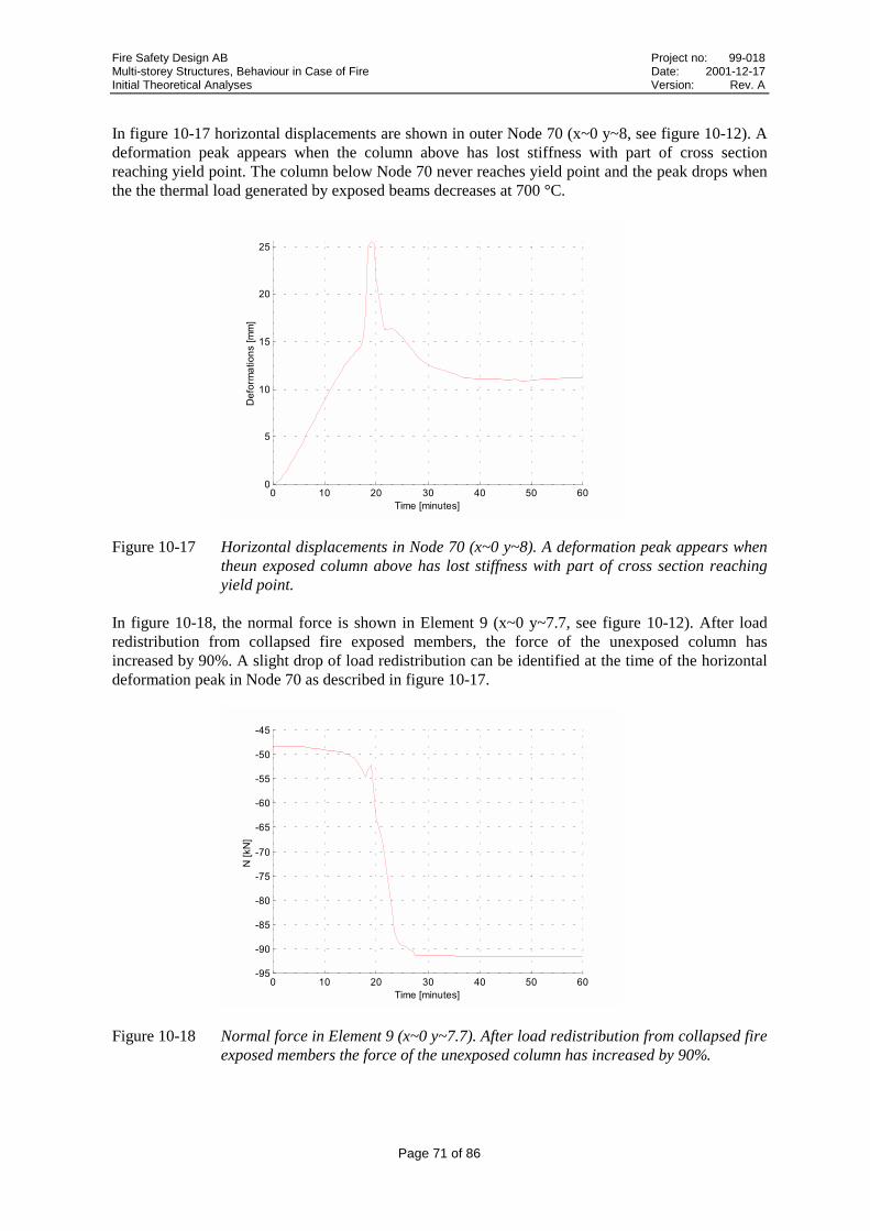
Fire Safety Design AB Project no: 99-018Multi-storey Structures, Behaviour in Case of Fire Date: 2001-12-17Initial Theoretical Analyses Version: Rev. A
Page 71 of 86
In figure 10-17 horizontal displacements are shown in outer Node 70 (x~0 y~8, see figure 10-12). Adeformation peak appears when the column above has lost stiffness with part of cross sectionreaching yield point. The column below Node 70 never reaches yield point and the peak drops whenthe the thermal load generated by exposed beams decreases at 700 °C.
� �� �� �� �� �� ���
�
��
��
��
��
�����#��*�
7+(�
��(#*���
Figure 10-17 Horizontal displacements in Node 70 (x~0 y~8). A deformation peak appears whentheun exposed column above has lost stiffness with part of cross section reachingyield point.
In figure 10-18, the normal force is shown in Element 9 (x~0 y~7.7, see figure 10-12). After loadredistribution from collapsed fire exposed members, the force of the unexposed column hasincreased by 90%. A slight drop of load redistribution can be identified at the time of the horizontaldeformation peak in Node 70 as described in figure 10-17.
� �� �� �� �� �� ��6 �
6 �
6��
6��
6��
6��
6��
6��
6��
6��
6��
�����#��*�
;���;�
Figure 10-18 Normal force in Element 9 (x~0 y~7.7). After load redistribution from collapsed fireexposed members the force of the unexposed column has increased by 90%.

Fire Safety Design AB Project no: 99-018Multi-storey Structures, Behaviour in Case of Fire Date: 2001-12-17Initial Theoretical Analyses Version: Rev. A
Page 72 of 86
6��� 6��� 6��� � ��� ��� ����
����
���
����
���
����
���,�#����%�&��� �����:�#��*��������
��1 �
Figure 10-19 Cross-sectional stress distribution in unexposed column Element 84 (x~4 y~12) after19.02 minutes. The stress is well below the yield limit throughout the section.
It was concluded that no global collapse occurred during the scenario due to large loadredistribution, although the thermal loads of exposed members generated near-critical stress in outerunexposed members.
The resulting behaviour must be considered unusual in real life. Indirect factors were not taken intoaccount in the theoretical, structural analyses. Lost integrity between compartments due to localcollapse would result in exposure in all compartments and global collapse eventually. The purposeof choosing the current load scenario was to be able to evaluate near critical condition as given bethe results, as well as a scenario of global collapse and a scenario of no critical conditions due tolocal collapse of one compartmentation. Slightly higher initial loading degree would have resulted inglobal collapse during the critical phase, after about 20 minutes of exposure. Less loading might nothave initiated the critical behaviour at all.
Provided structural design is done to permit load redistribution, e.g. not too large distance betweensupports, the overall loading degree may be of major importance to the global performance.
11 Conclusions
11.1 Columns
In literature no full-scale fire tests on partially exposed columns of slenderness ≥ 1.0 (“slendercolumns”) have been reported. Fire tests on partially exposed columns with slenderness < 1.0 (“shortcolumns”) have been performed but no negative influence on the load-bearing capacity comparedwith fully exposed columns have been observed. This is mainly due to the fact that the testsinvolved a wall that the columns reached within a few minutes, after which the direction ofhorizontal displacement was reversed, but it was also noted that the tested columns have been tooshort to be seriously influenced by a bowing effect due to the thermal gradient over the cross-section. Computer simulations indicate that there may exist a considerable problem for slendercolumns partially fire-exposed along its circumference.

Fire Safety Design AB Project no: 99-018Multi-storey Structures, Behaviour in Case of Fire Date: 2001-12-17Initial Theoretical Analyses Version: Rev. A
Page 73 of 86
Design methods including both plastic capacity and the critical Euler load, e.g. according toEurocode 3, were found to comply quite well with non-linear simulations and tests in most caseswith all 4 sides of the column exposed. For partially exposed slender columns the effect of thethermal moment caused by the cross-sectional gradient was found to be too large to be neglected.Exposure of about 50% of circumference was found to be the worst scenario for columns with a highslenderness (>1). It can be concluded that the collapse time will be reduced by 25-75% and thereduction is increased by increase in load utilisation. The best way to avoid the negative influence ofpartial exposure between 20 and 100% is to avoid this kind of exposure for slender columns.Otherwise the passive fire protection must be designed to resist partial fire exposure.
In practice, most columns are partially restrained in the vertical direction. This will increase thermalstresses for columns and especially for columns with 4-sided exposure. The results from the analysesof partially restrained columns indicate that the disadvantageous effect of increased thermal stressmay surpass the advantageous effect of the reduced buckling length. On the other hand, the increasedrestraint did not increase the degree of load redistribution to the rest of the structural system. Acomparison between partially restrained columns subjected to partial fire exposure and partiallyrestrained columns exposed on all four sides have not been covered by this report. Full-scale tests onpartially exposed columns of slenderness >1.0 are needed to quantify all the different effects.A generalised design code as Eurocode 3 must be reliable and useful for all combinations of partialfire exposure, restraint and slenderness within given limits of the code.
11.2 Beams
The collapse criterion set by design methods considering the bending moment capacity only,allowing the entire cross-section to yield (stress related to 2% strain) and taking advantage of the fullcorresponding yield stress, were found to comply with results from non-linear analyses and thestudied test. This was also the case for partially fire-exposed beams. It is found in this beam studythat there is no safety margin between the advanced calculation results and the simple calculations.As only a few comparisons are made examples can probably be found where the simple calculationmethods are more advantageous than the complex non-linear FEM-calculations. Thus the assumptionof using a design stress based on 2% strain and 100 % yielding of the cross-section is on the unsafeside and that is not acceptable. Another stress based on 1.0-1.5 % strain might be more relevant to beused in the simplified design method.
The collapse criterion based on a maximum deflection given by beam length divided by 30 as used inthe British fire tests more or less coincided with the cross-sectional criterion in the case of the testedand simulated beam. Also fire tests revealed that there was no safety margin to collapse at all for thesimplified method.
For statically indeterminate beams the theory of elasticity remains conservative when exposed tofire. The theory of plasticity was found to comply with non-linear analyses. There was indication,although it can not be fully concluded, that load redistributions begin as soon as loss of strength andstiffness starts to develop in any section.
11.3 Frames
The frame study in this report supports the experience of the Cardington tests and the computersimulations of these tests. The redistribution of loads, forces and moments from fire-exposedstructural members to the “cool” members of the frame structure are of great importance to improvethe fire resistance and may also avoid global collapse. The results from the frame analyses also

Fire Safety Design AB Project no: 99-018Multi-storey Structures, Behaviour in Case of Fire Date: 2001-12-17Initial Theoretical Analyses Version: Rev. A
Page 74 of 86
illustrate that load redistribution does begin before the collapse of single members starts. The overallloading degree is of major importance to the global performance.
One of the purposes of this work was to identify possibly redundant members in complex steelstructures, which do not need to be protected. To identify members as redundant, the remainingstructure must be designed to take the added loads transferred from collapsed members and loadspossibly redistributed from members subjected to capacity loss even before local collapse. Anoverall low loading degree in combination with a design that permits load redistribution could thenpossibly compensate for lack of fire protection of single members

Fire Safety Design AB Project no: 99-018Multi-storey Structures, Behaviour in Case of Fire Date: 2001-12-17Initial Theoretical Analyses Version: Rev. A
Page 75 of 86
12 Condensed Literature Review
The literature review is written in a very condensed format where the referenses are divided into 5group areas as shown below.
A Experience of structural behaviour and extent of damages in real building fires
B Fire tests of structures
B1 Fire resistance testsB2 Full scale fire tests
C Basic research on mechanical properties and on behaviour of structural elements
D FEM-modelling and computer simulation of fire tests
E Structural fire design methods
Group A literature has three references, which describe two real building fires at Broadgate Phase 8in London 1990 and at Churchill Plaza Building in Basingstoke 1991.
Group B literature has 8 references and describes fire resistance tests and full scale fire tests. UnderB1 different fire tests on external steel columns, unprotected structural steel, connections andcomposite slabs are presented. Under B2 three references (B5, 6, 7 & 9) describe the Cardingtontests, which are the most comprehensive and important ones. Also the BHP William Street FireTests, the BHP Collins Street Fire Tests and the fire tests at the Stuttgart-Vaihingen UniversityGermany are shortly presented. Reference (B8) is about fire tests on full scale floor assemblieswhich have been tested in NRC in Canada.
Group C literature has 6 references dealing with stress-strain relationships at elevated temperatures,modelling steel behaviour, passive fire protection, axial restraint of steel columns and structuralbehaviour.
Group D literature consists of 10 references on FEM-modelling dominated by simulating theCardington tests. Temperature calculations, simulation of the thermal and structural behaviour offire-exposed steel truss, steel beams and columns and steel frames as well as residual deformationafter fire are investigated in the different papers.
Group E literature consists of 14 references and the natural fire concept for design is dealt with inmost papers. Design methods are put forward especially beams, composite beams, columns, bracedframes and more complex structures.
12.1 A: Experience of structural behaviour and extent of damages in realbuilding fires
Two real building fires at Broadgate Phase 8 in London 1990 (A1) and at Churchill Plaza Buildingin Basingstoke 1991 (A2) have provided the opportunity to observe how modern steel framedbuildings can perform in fire.
In 1990 a fire developed in a partly completed 14 storey office block on the Broadgate developmentin London. The fire began inside a large site hut on the first level of the building. The temperatureswere estimated to be over 1000 °C. Following the fire structural elements covering an area of

Fire Safety Design AB Project no: 99-018Multi-storey Structures, Behaviour in Case of Fire Date: 2001-12-17Initial Theoretical Analyses Version: Rev. A
Page 76 of 86
approximately 40x20 m2 were replaced, but importantly no structural failure occurred and theintegrity of the floor slab was maintained during the fire. The direct fire loss was in excess of £ 25M,of which less than £ 2M was attributed to the structural frame and floor damage, the other costsresulted from smoke damage.
At the time of the fire the building was under construction and the passive fire protection to thesteelwork was incomplete. The sprinkler system and other active measures were not yet operational.
Following the Broadgate fire it could be seen that some of the elements had lost their load bearingcapacity although there were no sign of collapse. It was clear that the composite floor and supportingsteel deck had a major influence on the overall stability of the structure, acting as a membranedistributing loads from weakening members.
In 1991 a fire took place in the Mercantile Credit Insurance Building, Churchill Plaza, Basingstoke.The building constructed in 1988 was twelve storeys high. The columns had passive fire protectionin the form of boards and composite floor beams had spray applied protection. The underside of thecomposite floor was not protected and the structure was designed to have 90 minutes fire resistance.The fire started on the eight floor and stread rapidly to the tenth floor as the glazing failed. The fireprotection materials performed well and there was no permanent deformation of the steel frame. Thefire was believed to be comparatively “cool” due to the failure of the glazing permitting cross windto increase the ventilation. The estimated cost of repair of the building was over £ 5M, with most ofthe damage being due to the smoke. No structural repair was required to the protection of steel work.
The Basingstoke fire showed how well a fully protected building might perform but gave noindication of how safe the traditional approach actually is.
12.2 B: Fire tests on structures
B1 Fire resistance tests
4 papers are dealing with different fire resistance tests.
In the paper of Kruppa (B1) in 1981 20 tests were carried out on external steel columns situatedoutside a fire compartment. The results show that under certain conditions it is not necessary toprotect the columns.
D.E.Wainmann and B.R. Kirby, British Steel (B2) have produced two compendiums of UK standardfire test data on unprotected structural steel. The compendiums cover all the fire tests carried out inthe UK, according to BS476:Part 8:1972, on hot rolled structural steel sections in which themembers were either completely unprotected, or partially protected by materials used only in thefabric of structure, such as concrete, brick and blockwork. The information is presented in the formof a detailed description of the design, preparation and construction for each type of test element andis accompanied in an Appendix, by series of data sheets.
From the fire tests results reported, relationships between heating rate, member size, applied loadand fire resistance have been established for several types of load bearing elements based uponanalysis carried out.
The paper by Riihimäki (B3) deals with fire resistance of beam-to-column connections and theresearch is based upon four furnace tests at VTT. The report concludes that connections needpassive fire protection in the same extent as the steel members attached. However stresses due to

Fire Safety Design AB Project no: 99-018Multi-storey Structures, Behaviour in Case of Fire Date: 2001-12-17Initial Theoretical Analyses Version: Rev. A
Page 77 of 86
thermal expansion may sometimes be very important to take into account in the design ofconnections.
The last reference by Kruppa (B4) is focused upon the fire behaviour and simplified calculationmethods of composite beams. The results have also been used for numerical modelling by FEMcomputer programs.
B2 Full scale fire tests
4 of the 5 reports(B5, 6, 7 & 9) are dealing with the full scale Cardington tests on a BRE 8-storeyframe building. The building was designed and constructed to resemble a typical modern city centreoffice development (Fig ) On plan, the building covered an area of 21 m x 45 m with an overallheight of 33 m. The design complied with British Standard BS5950 and the Eurocodes 3 and 4.
The tests on the Cardington frame enabled the differences between the standard fire test and actualbehaviour to be studied. This led to the conclusion that the interaction with the cooler structuresurrounding the heat affected members within the fire compartment, was extremely beneficial to theheated members. The maximum steel temperature reached during the six fire tests was in excess of1100 °C. This occurred with no signs of structural collapse.
Three other large scale fire tests, the BHP William Street fire tests, the BHP Collins Street fire testsand the fire tests at the Stuttgart-Vaihingen University Germany are summarily presented.
The forth report (B8) from NRC presents results of 32 standard fire resistance tests conducted onfull-scale floor assemblies investigating the effects of subfloor material, gypsum board with differentperformance and fastenings. Many important results were obtained for different solutions.
12.3 C: Basic research on mechanical properties and on behaviour ofstructural elements
In the first reference by Bijard, Twilt and Witteveen the axial restraint of steel columns due tothermal expansion is looked upon.
2 of the 6 references viz Y. Anderberg (C2) and L. Twilt (C3) deal with mechanical properties athigh temperatures and how to model the steel behaviour. This modelling is useful as input in theFEM-structural programs.
In the TNO-report (C4) thermal properties and thermal response for natural fire curves and the ISO834 curve of beams and suspended ceilings are investigated. Numerical modelling of mechanicalresponse of beams and columns is also analysed in a limited extent.
At CTICM (C5) thermal and mechanical properties are discussed and the instability of columns withand without passive fire protection are investigated.
In reference C6 the response of structural elements under fire within a highly redundant structuresuch as a large building is discussed. The behaviour of the element under fire is strongly effected bythe surrounding parts which are not subjected to heating. The load redistribution to cooler partsmake some elements redundant.

Fire Safety Design AB Project no: 99-018Multi-storey Structures, Behaviour in Case of Fire Date: 2001-12-17Initial Theoretical Analyses Version: Rev. A
Page 78 of 86
12.4 D: FEM-modelling and computer simulation of fire tests
Advanced FEM-modelling of thermal and structural response of fire-exposed steel work ischaracterising all these 10 reports. Computer programs mentioned in these reports are shown in theTable below:
SAFIR SISMEF CEFICOSS LENAS
VULCAN DIANA ANSYS ABAQUS
INSTAF GCA(Global Collapse Analysis)
FIROSS TCD(Tempcalc-Design)
TASEF SUPER-TEMPCALC
Table 1 FEM-programs used to predict thermal and/or structural behaviour
In reference D1 the computer program LENAS was used to predict the behaviour of centrally loadedcolumns fully exposed to fire. The comparisons with tests gave a good agreement as concerns thecritical steel temperature.
Reference d2 presents residual deformation of steel beams after fire predicted by a special computerprogramme devoted to this study. The deformations obtained are largely influenced by the thermalgradient over the cross-section. A method is suggested to calculate the residual deflection of a steelmember after a fire. This is based on the assumption that the residual deflection is the same as itsdeflection at the maximum temperature due to applied load only.
In reference D3 the real behaviour of an external steel truss of the Paris museum “Centre Pompidou”was predicted by use of LENAS-MT. Eurocode 1 was used to obtain the external fire exposure andthe maximum temperature was assessed by Eurocode 3. Two furnace tests were also carried out asbasis and comparison with computer predictions. Very steep thermal gradients were measured andthese play a very important role in the deformation and consequently upon the fire resistance of thesteel structure.
Reference D4 illustrates thermal gradients and the load-bearing capacity of fire-exposed steel beamspartly embedded in concrete. The study is very comprehensive and cover most steel profiles on themarket with and without intumescent paint as passive fire protection. The computer program TCD isused to predict all design diagrams useful for the structural engineer.
In reference D5 an alternative, simplified approach for determining the thermal response of floor-ceiling assemblies comprised of a steel beam and concrete slab is presented. This approach utilisesan elementary finite difference model and is intended to be an improvement to the existing lumpedheat capacity approach for beams in accordance to the author’s opinion. However modern user-friendly software on the market today is probably to be preferred to this simplified model.
Reference D6 is presenting global collapse analyses of complex fire-exposed steel structuresrepresenting offshore platforms in the North Sea. The derrick of two platforms have been designedby the program GCA in an optimised way in order to fulfil the requirements on minimum collapsetime and in which direction the tower is allowed to collapse.
Reference D7 is a paper where the computer program SAFIR is used to study the behaviour of a 4storey frame structure with a fire in one of the bays. The capability of the program to predicttemperatures, deflections and axial deformation is demonstrated in a convincing way.

Fire Safety Design AB Project no: 99-018Multi-storey Structures, Behaviour in Case of Fire Date: 2001-12-17Initial Theoretical Analyses Version: Rev. A
Page 79 of 86
In reference D8 the ABAQUS computer program is used for simulating the Cardington tests asconcerns the composite structures under fire. The computations incorporate a simplified treatment ofthe reinforced slab behaviour to ensure numerical stability. The numerical model was able to followthe behaviour of the structure until the highest temperature of the fire was attained. The simulationsshowed that relatively good agreement has been achieved between predictions and the testmeasurements at all times during the fire.
Reference D9 and D10 are the main reports on the Cardington research project. The objective of theresearch was to gain a better understanding of the natural fire resistance and behaviour of steelframed multi-storey building subjected to fire attack and to correlate existing predictive numericalmodels.
Six major fire tests were carried out within the eight storey steel framed structure located within theBRE Large Building Test Facility at Cardington, Bedfordshire. It was found that this composite steelframed building possessed a very significant degree of inherent fire resistance even although thesteel floor beams remained entirely unprotected against fire.
A very comprehensive numerical modelling has been carried out by several universities and researchorganisations involved in the project to simulate thermal and structural behaviour observed in all thefire tests. The software used in the project are Ansys, Diana, Lenas, Sismef and Vulcan and thesimulations are often in a good agreement with measured behaviour. To simulate large deflections ofespecially the composite deck have led to necessary and advanced modifications of the originalsoftware code. On the whole the numerical modelling has shown that in the future very complicatedstructural fire behaviour can be predicted instead of relying on full scale fire testing. This work willalso establish the basis for a new more rational design methodology for steel framed buildingssubject to fire attack.
12.5 E: Structural fire design methods
Reference E1 is the very first manual on fire engineering design of steel structures and was veryappreciated at that time. Due to increased knowledge during the last 25 years new methods andmanuals are developed.
The second and third reference about Eurocodes present fire design of structural steel and actionsdue to fire. The two documents have been updated and are now under completion to be EN-standard.
Reference E4 gives guidance and simplified rules for fire design of composite beams. The designmethods have partly been introduced in Eurocode 3.
Reference E5 compares the traditional standard fire design with performance-based design and givesexamples of performance-based fire design of steel structures in buildings and on offshore platforms.The analytical tools are presented and the savings obtained by using engineering principles.
References E6 and E7 also deal with a comparison between traditional and performance-based firesafety engineering. Many applications are presented with optimised solutions on passive fireprotection based on calculations carried out by FEM-programs like TCD (see Table 1). In reference7 several examples of different design guides for slabs, beams, prestressed concrete units (T-beams,hollow slabs), concrete walls and offshore steel members are developed.
References E8-12 presents an approach to analysis of structural safety in case of fire that takes intoaccount active fire fighting measures and real fire characteristics. The project is called “Natural Fire

Fire Safety Design AB Project no: 99-018Multi-storey Structures, Behaviour in Case of Fire Date: 2001-12-17Initial Theoretical Analyses Version: Rev. A
Page 80 of 86
Concept” and was sponsored by ECSC. The project is carried out 1994-1998 and is divided into 5parts namely.
Part 1 Main textPart 2 Natural Fire ModelsPart 3 Equivalent ISO-time methodsPart 4 Fire CharacteristicsPart 5 Methodology to deduce from the probability data the “Design Natural Fire Curve”.
The work is very comprehensive and the structural engineer will be able to optimise the design byfollowing the guidelines given.
The ECCS Model Code (E13) on Fire Engineering comprises mechanical and thermal actions(advanced fire modelling), material properties (thermal and mechanical), simple calculations forsteel and composite members, connections, global structural behaviour and advanced calculationmodels.
“Structural Design for Fire Safety” (E14), is the latest manual on this subject and deals withconcrete, steel, composite and wooden structures.
12.6 References to Condensed Literature Review
A Experience of structural behaviour and extent of damages in real building fires
1. SCI – The Steel Construction InstituteStructural Fire Engineering, Investigation of the Broadgate Phase 8 Fire, 1991
2. BS, BRE, CTICM, University of Sheffield, TNO, SCI and DETRThe Behaviour of Multi-Storey Steel Framed Buildings in Fire, A European Joint ResearchProgramme, ISBN 0 900206 50 0, produced by British Steel 1999
B Fire tests of structures
B1 Fire resistance tests
1. J. Kruppa, CTICMProperties and service performance – Fire-resistance of External Steel Columns, Commission of theEuropean Communities – Technical Steel Research 1981.
2. D.E.Wainmann and B.R. Kirby, British SteelUnprotected Structural Steel-1&2 Compendium of UK Standard Fire Test Data, BRE- Fire ResearchStation and British Steel - 1988.
3. Juha RiihimäkiStructural Fire Design of Connections and other Structures in Multi-storey Steel Framed Buildings,Tampere University of Technology, 1991
4. B. Zhao, J. Kruppa, CTICMFire Resistance of Composite Slabs with Profiled Steel Sheet and of Composite SteelConcrete Beams, 2nd part: Concrete Beams, final report CTICM 1995

Fire Safety Design AB Project no: 99-018Multi-storey Structures, Behaviour in Case of Fire Date: 2001-12-17Initial Theoretical Analyses Version: Rev. A
Page 81 of 86
B2 Full scale fire tests
5. MRL- Research Melbourne LaboratoriesThe Effect of Fire in the Office Building at 140 William Street Melbourne, Australia, BHP, 1991.
6. D.M. Martin, B.R. Kirby and M.A. O’ConnorxBehaviour of a Multi-storey, Steel Framed Buildings Subjected to Natural Fire Effects, ECSCSponsored Research Project, Final Report, March 1998
7. M.A. Sultan, Y.P. Séguin and P. LerouxResults of Fire Resistance Tests on Full Scale Floor Assemblies, Institute for Research inConstruction, National Research Council Canada, Internal Report No 764, 1998
8. The Real Behaviour of Modern Largely Unprotected Steel Framed Buildings Under NaturalFire Conditions, TNO-report No 98-CVB-R 0457, 1998
9. BS, BRE, CTICM, University of Sheffield, TNO, SCI and DETRThe Behaviour of Multi-storey Steel Framed Buildings in Fire, A European Joint ResearchProgramme, ISBN 0 900206 50 0, produced by British Steel 1999
C Basic research on mechanical properties and on behaviour of structural elements
1. Yngve AnderbergModelling Steel Behaviour. Presented at the International Conference on Design of StructuresAgainst Fire, held at Aston University, Birmingham, UK on 15th and 16th April, 1986. Division ofBuilding Fire Safety and Technology. Lund Institute of Technology, January 1986.
2. L.Twilt, TNOStress-Strain Relationships of Structural Steel at Elevated Temperatures. Analysis of variousoptions & European proposal.. TNO-report BI-91-015, 1991
3. L.Twilt and C.Both, TNOTechnical Notes on the Realistic Behaviour and Design of Fire Exposed Steel and Composite Steel-Concrete Structures, TNO-report BI-91-069, 1991
4. CTICMxIncrease of the Fire Stability of Steel Structures with Protective Means, CTICM, 1991
5. J. Bijard, F.S.K., Twilt, L. and WitteveenAxial restraint of single steel columns due to rise of temperature , IBBC-TNO report BI-76-53,1976.
D FEM-modelling and computer simulation of fire tests
1. D.Talamonia, J.M. Franssen and N.ReichoBuckling of centrically loaded columns submitted to fire. Proceedings for “International Conferenceon Fire Research and Engineering, 10-15 September 1995, Orlando , Florida, USA. pp 533-538

Fire Safety Design AB Project no: 99-018Multi-storey Structures, Behaviour in Case of Fire Date: 2001-12-17Initial Theoretical Analyses Version: Rev. A
Page 82 of 86
2. Y.C. WangA theoretical investigation into the residual deformation of steel beams after a fire and its designimplications. Proceedings for “International Conference on Fire Research and Engineering, 10-15September 1995, Orlando , Florida, USA”, pp 539-544.
3. .D.Dhima, J. Kruppa, G. Fouquet and H. Leborgne - CTICMEffect of thermal gradient on the fire resistance of a 3 dimensional steel truss. Proceedings for“International Conference on Fire Research and Engineering, 10-15 September 1995, Orlando ,Florida, USA”, pp 545-556.
4. K. Lavesson, SwedenLoad-bearing Capacity of Fire-Exposed Steel Beams Partially Embedded in Concrete - ATheoretical Analysis. Project 95-017, Fire Safety Design, Lund, December 1996.
5. James A. MilkeA simplified model for estimating the thermal response of steel beam/concrete slab ceilingassemblies. Proceedings of Second International Conference on Fire research and Engineering, 3-8August 1997, Gaithersburg, Maryland, USA
6. L.N Tomlinsson, British Steel, V. Hüller, Studiengesellschaft Stahlanwendung, J.B. Schleich,Profilarbed, J. Kruppa, CTICM, L. Twilt, TNODesign and implementation of the computer code fire safety of structural steelwork (Fiross),European commission, technical steel research. EUR 18427, 1998
7. V.K.R Kodur, D.I. Nwosu, M.A. Sultan and J.M. FranssenApplication of the SAFIR Computer program for Evaluating Fire Resistance presented at the ThirdInternational Conference on Fire Research and Engineering in Chicago 4-8 October 1999.
8. A.M.Sanad and A.S. Usmani University of Edinburgh and M.A. O’Connor, British SteelFinite Element modelling of fire tests on the Cardington Composite Building presented at Interflam’99, 8 th International Fire Science & Engineering Conference in Edinburgh 29 th June-1 st July1999.
9. J.M. Rotter, A:M. Sanad, A:S. Usmani and M.Gillie, University of EdinburghStructural performance of redundant structures under local fires presented at Interflam’ 99, 8 thInternational Fire Science & Engineering Conference in Edinburgh 29 th June-1 st July 1999.
10. BS, BRE, CTICM, University of Sheffield, TNO, SCI and DETRThe Behaviour of Multi-storey Steel Framed Buildings in Fire, A European Joint ResearchProgramme, ISBN 0 900206 50 0, produced by British Steel 1999
11. Yngve AnderbergSteel Columns Partially Fire-Exposed- A Theoretical Study. Fire Safety Design, Lund, Sweden,March 1998.
E Structural fire design methods
1. Pettersson, Magnusson, Thor:Fire Engineering Design of Steel Structures, Swedish Institute of Steel Construction, Stockholm1976.

Fire Safety Design AB Project no: 99-018Multi-storey Structures, Behaviour in Case of Fire Date: 2001-12-17Initial Theoretical Analyses Version: Rev. A
Page 83 of 86
2. Eurocode 3 Design of steel structures, Part 1.2 Structural Fire Design, Draft prENV 1993-1-2,August 1993.
3. ENV 1991-2-2, Basis of design and actions on structures, Part 2-2 Actions on structuresexposed to fire, CEN Brussels 1994.
4. L.Twilt and C.Both, TNOTechnical Notes on the Realistic Behaviour and Design of Fire Exposed Steel and Composite Steel-Concrete Structures, TNO-report BI-91-069, 1991
5. B. Zhao, J. Kruppa, CTICMFire Resistance of Composite Slabs with Profiled Steel Sheet and of Composite SteelConcrete Beams, 2nd part: Concrete Beams, final report CTICM 1995
6. Yngve AnderbergEuropean Experiences in Fire Design of Structural Steel. Presented at the ASCE-StructuresCongress in Chicago 15-18 April 1996. Fire Safety Design, Lund, Sweden, 1996.
7. Yngve Anderberg, Sebastian Jeansson, Jens OredssonGlobal Analysis of Fire-Exposed Steel Structures. Presented at the Swedish Steel BuildingConference of Swedish Institute of Steel Construction in Sundsvall 18 October 1996. Fire SafetyDesign, Lund, Sweden, 1996.
8. Yngve AnderbergPerformance-based Fire Safety Engineering in Practise - Presented at a seminar held at University ofBandung, Indonesia on November 25, 1997, Fire Safety Design, Lund Sweden.
9. Yngve AnderbergFire Engineering Design of Structures based on Design Guides - Presented at the SecondInternational Conference on Performance-Based Codes and Fire Safety Methods, Maui, Hawaii, May5-9, 1998.
10. J.B. Schleich and L-. Cajot, ARBED et alCompetitive Steel Buildings Through Natural Fire Safety Concept, CEC-Project, Part 1, ( Maintext.) ARBED, March 1999
11. J-M. Franssen and J.F. Codorin, University of Liége, Belgium et alCompetitive Steel Buildings Through Natural Fire Safety Concept, CEC-Project, Part 2 (Workinggroup 1 Equivalent ISO-Time Methods and Working group 2: Natural Fire Models) , ARBED,March 1999
12. L.Twilt and J. Van Oerle, TNO, The Netherlands et alCompetitive Steel Buildings Through Natural Fire Safety Concept, CEC-Project, Part 3, (Workinggroup 3: Fire Characteristics for Use in a Natural Fire Design of Building Structures) , ARBED,March 1999
13. M. Fontana and C. Fetz, ETH, Zürich, Switzerland et alCompetitive Steel Buildings Through Natural Fire Safety Concept, CEC-Project, Part 4, (Workinggroup 4: Statistics), ARBED, March 1999

Fire Safety Design AB Project no: 99-018Multi-storey Structures, Behaviour in Case of Fire Date: 2001-12-17Initial Theoretical Analyses Version: Rev. A
Page 84 of 86
14. J.B. Schleich and L-. Cajot, ARBED et alCompetitive Steel Buildings Through Natural Fire Safety Concept, CEC-Project, Part 5, (Workinggroup 5: Methodology to Deduce from the Probability Data the “Design Natural Fire Curve”),ARBED, March 1999
15. J.Kruppa, Gerry Newman, J.B. Schleich and Leen TwiltECCS Model Code on Fire Engineering, 1999
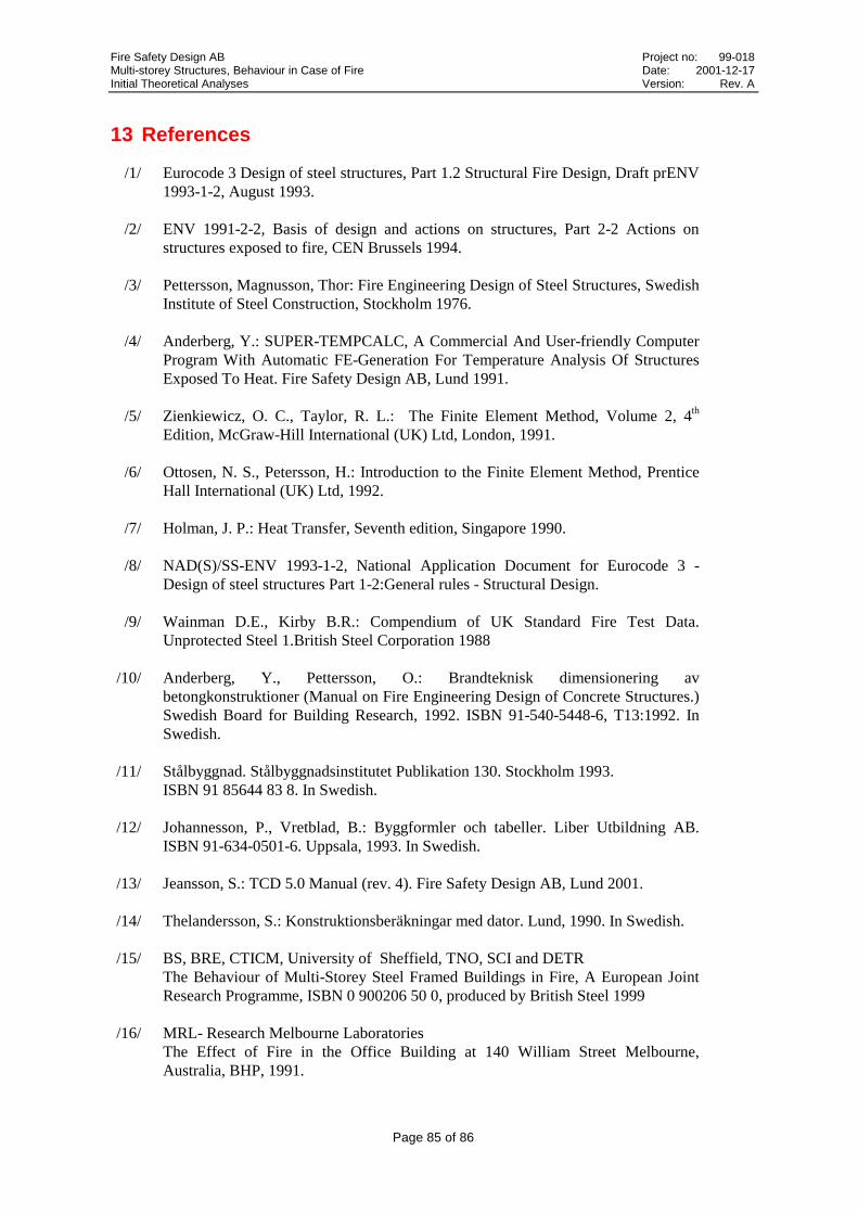
Fire Safety Design AB Project no: 99-018Multi-storey Structures, Behaviour in Case of Fire Date: 2001-12-17Initial Theoretical Analyses Version: Rev. A
Page 85 of 86
13 References
/1/ Eurocode 3 Design of steel structures, Part 1.2 Structural Fire Design, Draft prENV1993-1-2, August 1993.
/2/ ENV 1991-2-2, Basis of design and actions on structures, Part 2-2 Actions onstructures exposed to fire, CEN Brussels 1994.
/3/ Pettersson, Magnusson, Thor: Fire Engineering Design of Steel Structures, SwedishInstitute of Steel Construction, Stockholm 1976.
/4/ Anderberg, Y.: SUPER-TEMPCALC, A Commercial And User-friendly ComputerProgram With Automatic FE-Generation For Temperature Analysis Of StructuresExposed To Heat. Fire Safety Design AB, Lund 1991.
/5/ Zienkiewicz, O. C., Taylor, R. L.: The Finite Element Method, Volume 2, 4th
Edition, McGraw-Hill International (UK) Ltd, London, 1991.
/6/ Ottosen, N. S., Petersson, H.: Introduction to the Finite Element Method, PrenticeHall International (UK) Ltd, 1992.
/7/ Holman, J. P.: Heat Transfer, Seventh edition, Singapore 1990.
/8/ NAD(S)/SS-ENV 1993-1-2, National Application Document for Eurocode 3 -Design of steel structures Part 1-2:General rules - Structural Design.
/9/ Wainman D.E., Kirby B.R.: Compendium of UK Standard Fire Test Data.Unprotected Steel 1.British Steel Corporation 1988
/10/ Anderberg, Y., Pettersson, O.: Brandteknisk dimensionering avbetongkonstruktioner (Manual on Fire Engineering Design of Concrete Structures.)Swedish Board for Building Research, 1992. ISBN 91-540-5448-6, T13:1992. InSwedish.
/11/ Stålbyggnad. Stålbyggnadsinstitutet Publikation 130. Stockholm 1993.ISBN 91 85644 83 8. In Swedish.
/12/ Johannesson, P., Vretblad, B.: Byggformler och tabeller. Liber Utbildning AB.ISBN 91-634-0501-6. Uppsala, 1993. In Swedish.
/13/ Jeansson, S.: TCD 5.0 Manual (rev. 4). Fire Safety Design AB, Lund 2001.
/14/ Thelandersson, S.: Konstruktionsberäkningar med dator. Lund, 1990. In Swedish.
/15/ BS, BRE, CTICM, University of Sheffield, TNO, SCI and DETRThe Behaviour of Multi-Storey Steel Framed Buildings in Fire, A European JointResearch Programme, ISBN 0 900206 50 0, produced by British Steel 1999
/16/ MRL- Research Melbourne LaboratoriesThe Effect of Fire in the Office Building at 140 William Street Melbourne,Australia, BHP, 1991.

Fire Safety Design AB Project no: 99-018Multi-storey Structures, Behaviour in Case of Fire Date: 2001-12-17Initial Theoretical Analyses Version: Rev. A
Page 86 of 86
/17/ D.M. Martin, B.R. Kirby and M.A. O’Connor: Behaviour of a Multi-storey, SteelFramed Buildings Subjected to Natural Fire Effects, ECSC. Sponsored ResearchProject, Final Report, March 1998.
/18/ BS, BRE, CTICM, University of Sheffield, TNO, SCI and DETRThe Behaviour of Multi-storey Steel Framed Buildings in Fire, A European JointResearch Programme, ISBN 0 900206 50 0, produced by British Steel 1999.
/19/ The Real Behaviour of Modern Largely Unprotected Steel Framed Buildings UnderNatural Fire Conditions, TNO-report No 98-CVB-R 0457, 1998
/20/ Wiberg, N.E.,: Finita Elementmetoden. ISBN 91-40-03768. Lund 1975.
/21/ BKR, Boverkets Konstruktionsregler. Karlskrona 1998. In Swedish.