Multi-‐Site Dual ISP Redundant Site-‐to-‐Site VPN with OSPF Failover
10
MultiSite Dual ISP Redundant SitetoSite VPN with OSPF Failover This document covers the configuration of a multisite VPN scenario with dual ISPs and quadruple VPN tunnels at each site. This scenario has three sites, two remote branches and one main site. Each location has two ISP connections, the remote branches do not connect directly to each other, only to the main site but with a full mesh configuration (4 tunnels per remote site). This design will support the loss of a single connection at all of the three sites concurrently while maintaining full connectivity. To get started, the below is a quick (albeit messy) diagram of the scenario network. The black lines represent physical ISP connections, the red lines represent VPN tunnels from the main site’s primary ISP connection and the yellow lines represent VPN tunnels from the main site’s secondary ISP connection. Below the diagram there is a layout of each of the VPN tunnels with addressing. The addressing at either end of the line is the physical interface addressing on the firewalls and the the addressing below each of the lines at either end represent the addresses on the tunnel interfaces on each end of the VPN tunnel. Each of the ISP connections have a separate address range in the 10.75.200.x to 10.75.205.x range, this is to best simulate a true distributed environment with completely separate address ranges. Also the tunnel interfaces utilize a /30 subnet, this is because there will never be more than two tunnel interfaces as a part of a single VPN tunnel so there is no need to waste addresses by using a larger subnet. This guide assumes that the ISP connections at each site are alive and routing correctly. By Mike Lutgen January 2016
Transcript of Multi-‐Site Dual ISP Redundant Site-‐to-‐Site VPN with OSPF Failover

Multi-‐Site Dual ISP Redundant Site-‐to-‐Site VPN with OSPF Failover
This document covers the configuration of a multi-‐site VPN scenario with dual ISPs and quadruple VPN tunnels at each site. This scenario has three sites, two remote branches and one main site. Each location has two ISP connections, the remote branches do not connect directly to each other, only to the main site but with a full mesh configuration (4 tunnels per remote site). This design will support the loss of a single connection at all of the three sites concurrently while maintaining full connectivity. To get started, the below is a quick (albeit messy) diagram of the scenario network. The black lines represent physical ISP connections, the red lines represent VPN tunnels from the main site’s primary ISP connection and the yellow lines represent VPN tunnels from the main site’s secondary ISP connection. Below the diagram there is a layout of each of the VPN tunnels with addressing. The addressing at either end of the line is the physical interface addressing on the firewalls and the the addressing below each of the lines at either end represent the addresses on the tunnel interfaces on each end of the VPN tunnel. Each of the ISP connections have a separate address range in the 10.75.200.x to 10.75.205.x range, this is to best simulate a true distributed environment with completely separate address ranges. Also the tunnel interfaces utilize a /30 subnet, this is because there will never be more than two tunnel interfaces as a part of a single VPN tunnel so there is no need to waste addresses by using a larger subnet. This guide assumes that the ISP connections at each site are alive and routing correctly.
By Mike Lutgen January 2016

To begin, create the tunnel interfaces on each of the firewalls (Network-‐>Interfaces-‐>Tunnel), assign the appropriate IP addressing to each of them and add them to the appropriate zones. Keep in mind that the tunnel interface addressing must match on either side of the tunnel so keep track of which interfaces have which addresses assigned (easiest to just go in order). In this scenario they will all be added to a single zone called “vpn”; this is a generally insecure method (as intra-‐zone traffic is permitted by default). This configuration is only recommended

as an initial setup measure to verify traffic is passing correctly before imposing security restrictions on it. Don’t worry about assigning a Virtual router to these interfaces yet. In this scenario each remote site will have 4 tunnel interfaces because there will be a total of 4 tunnels built and the main site will have 8 tunnel interfaces because it will have 8 tunnels.
Next move to IPSec Tunnels, (Network-‐>IPSec Tunnels) there will be 4 tunnels for each remote site and 8 at the main site. Give each tunnel a name, specify the tunnel interface to be used for that tunnel and in the drop-‐down for IKE Gateway click the link to create a new IKE Gateway.

In the new IKE Gateway window specify the name, the physical interface this tunnel will be tied to, select the IP address in the drop-‐down (optional if only a single IP address is assigned to that interface), and specify the peer address and pre-‐shared key for this tunnel.
After clicking OK on the IKE Gateway creation window, select that newly created IKE Gateway from the drop-‐down back in the IPSec Tunnel creation window, then check the box for Tunnel Monitor, specify the IP address for the tunnel interface on the other side of this tunnel (the tunnel interface’s address on the peer side), and select the default Monitor profile (this will be adjusted later, create a unique Monitor Profile right away if desired). Do not specify any Proxy IDs, leave everything on that tab blank. Each of these tunnels will remain red (down) until the configuration is completed and committed on both of the peers. Now move to Virtual Routers, every site will have 3 virtual routers (no matter the number of tunnels); one for each ISP and one for all other interfaces. The reason for this is that in order to communicate each ISP connection will need a next-‐hop. Multiple default gateway routes in a single virtual router will not accomplish this and traffic originating from the firewall does not follow Policy-‐Based Forwarding rules. Create each of the ISP virtual routers, add the physical interface of the firewall that is connected to that ISP and in static routes add a default route for that ISPs next hop.

After that, create the third virtual router and add all other interfaces to this one, including all tunnel interfaces. If local internet access is desired at that site, add a default route pointing to the virtual router of the primary ISP as the next hop.
Then move to Redistribution Profile and click Add. Name it, set priority (1), select Connect, and then add all connected interfaces that should have their directly connected address ranges advertised through OSPF to the other locations. Optionally create a secondary redistribution profile with a priority of 2 selecting Static and specifying static routes you’d like to redistribute to other locations in the middle column (under Destination).

Switch to the OSPF tab and click the selection box to enable OSPF and give a router ID. (Note: this is NOT an IP address, though it is specified by 4 octets separated by periods just like an IP address; generally using the IP address of the device can simplify troubleshooting)
Click Add to add an OSPF area, give it an area ID (for most small environments area 0.0.0.0 will work perfectly fine) and click on the Interface tab. Add each of the tunnel interfaces here, accepting all of the default values except for the Link Type, specify p2p for this. Toward the end of this document tuning operations are covered to adjust these timers for faster failover times.
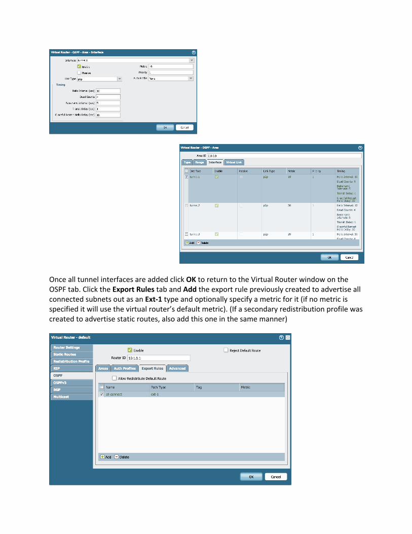
Once all tunnel interfaces are added click OK to return to the Virtual Router window on the OSPF tab. Click the Export Rules tab and Add the export rule previously created to advertise all connected subnets out as an Ext-‐1 type and optionally specify a metric for it (if no metric is specified it will use the virtual router’s default metric). (If a secondary redistribution profile was created to advertise static routes, also add this one in the same manner)

At this point, the configuration to bring up the VPN tunnels and the OSPF neighbors is complete. Verify that a security rule is created allowing traffic to & from the “vpn” zone for the desired areas of the network at each location and Commit the changes. If all configuration was completed successfully there should be 4 tunnels at each remote site showing green and 8 tunnels at the main site showing just the same. Remote Site 1
Remote Site 2
Main Site
Switch over to Virtual Routers and select More Runtime Stats for the virtual router that has all of the tunnel interfaces associated with it. On the OSPF tab, select the Neighbor tab; in each of the remote sites there should be 4 neighbors and at the main site there should be 8.

If all is correct so far, then moving to the Routing tab there should be routes for all of the local subnets specified in the redistribution profiles at each of the sites with the flags A O1 indicating that they are Active routes, they were learned via OSPF and they are Ext-‐1 routes.
Failover times in this configuration will be approximately 10-‐15 seconds, to decrease this follow the below tuning methods.

Adjust the Monitor profile – this will determine how long a tunnel interface is kept alive when it’s monitored address is no longer accessible. (Network-‐>Monitor) Depending on the stability of the connections at each location this can be lowered from the default of 3 second intervals with a threshold of 5. In the lab this is configured at 2 second intervals with a threshold of 2. At the very least, this should be switched from the Action of “wait-‐recover” to “fail-‐over”. This will create faster failovers during outages. Adjust the OSPF timers – this will determine reconvergence times when an interface drops. (Network-‐>Virtual Routers-‐><virtual router with the OSPF config>-‐>OSPF – Edit area 0.0.0.0) For each of the tunnel interfaces the Timing can be adjusted, primarily focusing on the Hello Interval and Dead Counts timers. The timers between each neighbor connection need to match, if they do not the neighbor will not come up, or it may come up but will cause route flapping. Again, the ability to tune these will depend on the stability of the connection at the particular location but in the lab these are currently set at 5 and 3 respectively with failover times at 3-‐4 seconds. Adjusting either of these two mechanisms too aggressively will cause flapping interfaces and routes and will lead to a very unstable environment; when tuning, it is best to be not aggressive enough than too aggressive.