MULTI - Hummel.com · Replace controller board ... regulating the temperature of hot-runner molds....
16
Operating Instructions 05 / 12 (Subject to technical modifications) MULTI HUMMEL AG Division EL Robert-Bunsen-Straße 3 D-79211 Denzlingen, GERMANY Phone: +49(0)7666/91110-970 Fax: +49(0)7666/91110-9799 Internet: www.hummel.com
Transcript of MULTI - Hummel.com · Replace controller board ... regulating the temperature of hot-runner molds....

Operating Instructions 05 / 12
(Subject to technical modifications)
MULTI
HUMMEL AG Division EL
Robert-Bunsen-Straße 3 D-79211 Denzlingen, GERMANY
Phone: +49(0)7666/91110-970 Fax: +49(0)7666/91110-9799 Internet: www.hummel.com

Table of Contents
General Information Safety Instructions ........................................................................................................................3
Warranty .......................................................................................................................................3
Intended Use.................................................................................................................................3
General Instructions......................................................................................................................3
Set-Up...........................................................................................................................................4
Cleaning........................................................................................................................................4
Maintenance .................................................................................................................................4
Disposal ........................................................................................................................................4
Controller Start-Up.........................................................................................................................................5
Front View.....................................................................................................................................5
Setpoints, Zones Switch off ..........................................................................................................6
Function Keys ...............................................................................................................................6
Alarm indicators ............................................................................................................................7
Soft-Start Ramp ............................................................................................................................7
Mold Memory ................................................................................................................................7
Change Parameters......................................................................................................................8
Parameters, Factory Preset ..........................................................................................................9
Manual Mode ..............................................................................................................................10
WireTest (optional)......................................................................................................................11
Replacing Fuses .................................................................................................................12 + 13
Replace controller board.............................................................................................................14
Connections Load, Thermocouple ...................................................................................................................15
Alarm Connector .........................................................................................................................16
Specifications ....................................................................................................................................................16
2

Safety Notices Carefully read these operating instructions prior to putting the product into service.
Only qualified personnel with sufficient electrotechnical knowledge may service the device. Be sure to disconnect the mains plug before opening the housing!
When replacing fuses, be sure to use the same type of fuse (see “Replacing Fuses“).
Prior to plugging in the mold cables, be sure to verify that all connectors have been properly connected (see “Connections” or connection diagram for special pin assignments).
Check power supply cable and mold cables for potential defects on a regular basis! If cable sheath is damaged, be sure to use a new connecting cable!
Warranty All plug-in controllers are subject to a 2-year warranty starting on the day of
shipment of the product. Excluded from coverage is damage due to improper handling, wrong connection or non-intended use (see below).
Return goods must be sent to HUMMEL AG’s EL Division using the original packaging, postage prepaid.
Intended Use The plug-in controllers are industrial temperature controllers designed for
regulating the temperature of hot-runner molds. To this end, the temperature of each control zone is monitored by a temperature sensor whose input is used to adjust the power output for the heating element as appropriate.
An external temperature fuse must be used for overtemperature protection in the event of malfunction.
The manufacturer shall not be liable for damage due to improper use of the device.
General Information A separate control zone is required for each load to be connected.
A “control zone” consists of a temperature sensor input and a load output including a fuse.
When wiring the molds, be sure to assign them to the correct pins (see “Connections”).
All unused controller modules must be switched off.
A heat-resistant flexible cable must be used as a connecting lead for the load circuits. For the temperature sensors, a special compensating lead is required! Leads and cables are available as original accessories.
3

Set-Up Place the device on a stable flat working surface. The display should be at eye-level with the
user.
Cooling fans prevent overheating of the output stage. The vents are at the unit’s rear and underside (MULTI 18 – 36). Be sure that the air can circulate freely through the appropriate vents.
Cleaning The housing and the control panel may be cleaned with a soft cloth saturated with alcohol.
Do not use acid cleaners or scouring agents!
Maintenance The device must be regularly subjected to a safety check complying with BGV A2
requirements (protection against accidents).
Clean the fan dust filter of MULTI 18 – 36 devices at regular intervals. Replace the filter as appropriate, depending on its working condition and duration of use.
The ventilation slots should be regularly checked for obstruction and cleaned if necessary. However, this may only be done by qualified service personnel with adequate electrotechnical knowledge.
No other maintenance work is required for the device beyond the tasks specified above. Should malfunction occur, please contact the manufacturer.
Disposal Once the device has reached the end of its service life, return it to the manufacturer for
proper disposal.
This device satisfies the essential protection requirements
specified in pertinent EU Directives (as at 2010)
4

Start-Up The MULTI 6–36 hot-runner controllers are designed for connection to a three-phase power supply
source (see “Technical Data”). The unit features a CEE plug for this purpose. The mains switch, which disconnects the device completely from the power supply, is located on the rear panel.
After checking carefully that all connections have been made correctly, connect the mold to the controller. The alarm connector (accessory) allows you to establish a connection to the injection molding machine as well. Connect the mains cable, then turn on the controller via the mains switch. This triggers a query prompting you to decide whether the control parameters should be optimized for the respective hot-runner mold or not. Optimization is necessary only when a mold is connected for the first time. Setting optimization to OFF (OPTI-N) accelerates the heating-up process. However, if the setpoint values are retrieved from the tool memory, optimization is always required. In the Parameters menu, you can optionally enter a starting time of 0–4 minutes. If no entry is made, the system will start without optimization after the set time period has elapsed. If you set a starting time of 0 minutes, an entry is always required.
Adjust the setpoint values or load a mold program stored in the mold memory. Be sure to switch off all control zones that are not used currently! (See “Setting Setpoints”, “Zones Switch off”).
This causes the controller to heat up the mold in a uniform manner. Moist heating elements are dried in the process and the “temperature deviation” alarm indicator is set flashing for all active zones (soft-start ramp). The temperature is indicated in the “actual value” window in °C. For all deactivated zones, the standby mode is indicated.
Once the target temperatures have been reached, production can be started using the factory-specific settings.
Should problems occur during start-up, the alarm indicators of the respective zone provide information on the cause of the trouble (see Alarm indicators).
Front View Actual Value window Alarm indicators Dialog window
5
SETPOINT button
Output POWER / % button
BOOST button
TEMP DOWN button
PROGRAMMING / ENTER button
CANCEL PROGRAMMING / ZONE OFF
button
UP/DOWN buttons
Heating pulse indicator
MANUAL button
Setpoint window, power / % indication
MOLD MEMORY button

Setting Setpoints / Switching Off Control Zones
Button Command Display / Result Display setpoint Upon pressing this button, the setpoints are displayed, or
oFF for the non-active zones. The button indicator lights up. The dialog window shows Z ALL. Use Z COPY to set the same setpoint value for all active zones.
6
Select zone The selected zone is indicated in the dialog window. Z ALL for all zones.
Confirm zone The selected zone number is flashing, or all zone numbers if Z ALL. The dialog window shows TEMP. If you selected Z COPY, the setpoint value is displayed in the central setpoint window.
Set setpoint, Change the setpoint with the UP / DOWN buttons. - Switch off zone Keeping the ESC / OFF button pressed for a few seconds
and then operating it again, switches off the selected zone. - Switch on zone Pressing the OK / PRG button 2 times will switch on the
selected zone. This automatically restores the lastused setpoint.
Confirm setting Stores the changed values.
Setpoint display off Button indicator off. Back to standard control mode. Increased setpoints will be reached with 100% power output!
* Exit without saving:
Cancel Pressing this button returns you to the previous
programming step without saving the changed values.
Function Keys Button indicator lights up upon activation of respective button (On).
Output power Pressing this button once indicates the output power in % of the maximum in the setpoint display. Pressing it again shows you the load current (in amperes). The button indicator % or A lights up. Pressing the button once more returns to the setpoint value.
Boost function active Increases temperature temporarily. (also externally via alarm connector)
Standby active Decreases temperature permanently. (also externally via alarm connector). Stop operation Pressing the button longer, switches off the outputs. The
button LED starts flashing. To resume operation, push the button again.
* Mold Memory, Manual Mode and optional Wire Test see separate chapter.

Soft-Start Ramp Active by: Start-Up, Heating after standby or alarm.
RMPEND
UNTEMP
OVTEMP Setpoint
RMP T1 (seconds for 1 °C)
RMPPSERMP T2 (seconds for 1 °C)
Alarm Indicators
Thermocouple alarm Lights up in case of TC malfunction (open, reversal). The instantaneous value display
shows "- - -" or the temperature of the controller by TC reversal. If Automode is active, the display shows alternating " - - - " and " - A - ".
Temperature deviation alarm
Flashes during the heating-up phase of the soft-start ramp. Lights up continuously if the temperature exceeds or falls below set limits. In case of overtemperature, the power supply is interrupted.
Load alarm Lights up if the set maximum current is exceeded (see Change Parameters) or flashes
by open load. In case of overcurrent, the power supply is interrupted.
Mold Memory Button Command Display
Call up memory function The button indicator lights up. The zone numbers are displayed flashing in the Actual Value windows and the current memory (1 – 6) location is displayed in the Dialog window.
Select memory location The selected memory location is displayed in the Dialog window.
Confirm memory location “LOAD” is displayed in the Display window.
Select function Use “LOAD” to call up the stored data; use “SAVE” to save the set values in the selected memory location.
Confirm entry Dialog window off. Back to control operation. The mold memory button LED will be flashing during
the process of saving the values.
7
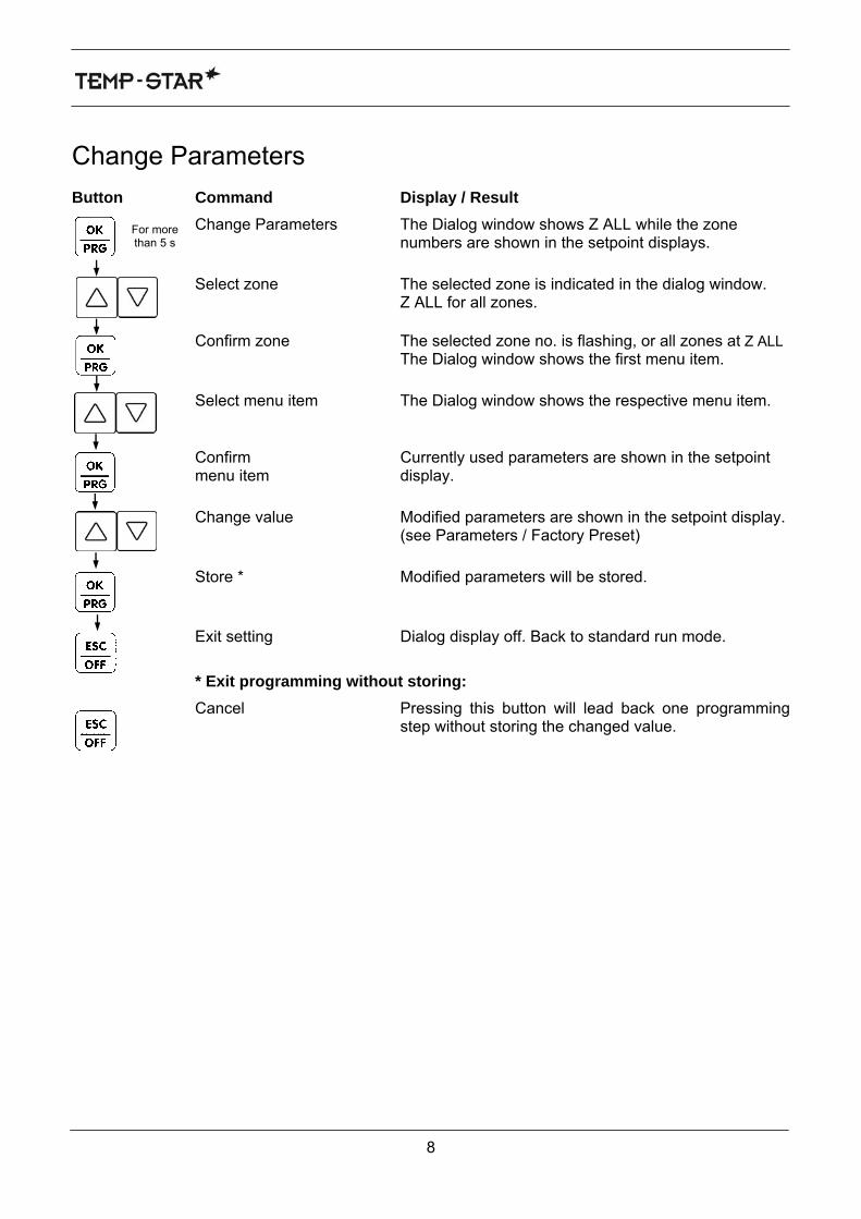
Change Parameters Button Command Display / Result
Change Parameters The Dialog window shows Z ALL while the zone numbers are shown in the setpoint displays.
For more than 5 s
Select zone The selected zone is indicated in the dialog window. Z ALL for all zones.
Confirm zone The selected zone no. is flashing, or all zones at Z ALL
The Dialog window shows the first menu item.
Select menu item The Dialog window shows the respective menu item.
Confirm Currently used parameters are shown in the setpoint
menu item display.
Change value Modified parameters are shown in the setpoint display. (see Parameters / Factory Preset)
8
Store * Modified parameters will be stored.
Exit setting Dialog display off. Back to standard run mode.
* Exit programming without storing:
Cancel Pressing this button will lead back one programming step without storing the changed value.

Parameters (Factory Preset)
Menu Item Name Function Range Standard Factory-preset
The following parameters can only be set for all zones
O V T E M P Overtemperature Limit value, alarm output 1 0 - 50°C above
setpoint 10°C
U N T E M P Undertemperature Limit value, alarm output 2 0 - 50°C below setpoint
10°C
R M P E N D Ramp end Final temperature ramp 1 80 - 120°C 120°C
R M P T 1 Rise, ramp 1 Heating speed, ramp 1 0=synchronisation + ramp Off
2 - 10 seconds for 1°C 4 seconds
R M P T 2 Rise, ramp 2 Heating speed, ramp 2 0=synchronisation + ramp Off
2 - 10 seconds for 1°C 2 seconds
R M P P S E Ramp pause Pause between ramps 1 + 2 1 - 10 minutes 1 minute
A U T O Automode * Automatic control if TC is open (average output power) 1 = On; 0 = Off 0 (Off)
T E M P D N Standby Temperature below setpoint 10 – 200°C 50°C T C T Y P Thermocouple Type of thermocouple J, L option K (h) J
U N I T Temperature unit °C or °F C or F °C P R E S E T Preset Reset to factory settings - - F W V E R Current firmware version Software version controller card V… -
C O D E Access code Lock function for parameters 0 - 250 0 (inactive)
S Y N C Compound heating Deactivates soft-start synchronization 1 = On; 0 = Off 1 (On)
W A I T Starting time Upon switching it on, the controller starts without optimization.
0-4 minutes 0 (manual start)
T C T I M Thermocouple response time
Time period for thermocouple to detect temperature increase or decrease.
0-10 minutes 0 (Off)
* Automode function is available only after trouble-free operation for approx. 15 min!
The following parameters can be set individually for each zone
T E M P U P Boost function Temperature above setpoint 5 - 60°C 20°C U P T I M E Boost time Duration of boost process 0 - 180 sec. 20 seconds
C U R R Overload Limit value 1 - 16 A 16 A T M P M A X Setpoint limitation Max. setpoint value permitted 50–500°C 450°C
The following functions are optional features for the WireTest diagnostic function
W T P U L S WireTest pulse % power output for the test 10 – 50% 20% W T T E M P WireTest temperature Temperature increase ΔT during
test 10–50 K 10 K
W T T I M E WireTest time Max. testing time / zone during test 30–120 s 60 s
9

Manual Operation
Manual operation means that your hot-runner mold is not automatically controlled and regulated and not switched off automatically in the event of overtemperature! This could lead to overheating and destruction of the hot runner!
Button Command Display
Manual operation “OFF” is displayed in the Setpoint windows of all zones that are not operated manually. The button indicator is on.
Select zone The selected zone is indicated in the Dialog window.
Confirm zone Sets the selected zone number flashing.
Set % of power output Use the UP/DOWN buttons to set the power in a percentage of the output.
- Manual operation OFF Keeping the ESC/OFF button pressed briefly and then operating it again switches off manual-mode operation for the current zone.
- Manual operation ON Operate the OK/PRG button twice to switch on the selected zone. This calls up the last used percentage value of the power output.
Confirm entry This saves the changes made.
Terminate entry Button indicator OFF. Back to control operation. The current value and “PLS” will be displayed alternatingly in the Setpoint window of the “manual operation” zones.
* Cancel without saving:
Cancel Operating this button returns you to the previous step in the programming sequence. Current changes are aborted.
* Turning off the device with the mains switch deactivates manual operation!
10

WireTest (optional) Button Command Display
Call up diagnostic function The button indicator lights up and “Test ?” is displayed in the Dialog window.
Select function Start the diagnostic process with OK. This displays “WAIT” in the Dialog window. If the function has been released for a warm system, the controller automatically waits until the system has cooled down to an optimal temperature for starting the diagnosis. Thereafter, one zone after another is checked for wiring errors. Following termination of the diagnosis across all zones, “END” is displayed in the Display window for confirmation and the results of the diagnosis are displayed in the zone windows.
Terminate diagnostic function Dialog display OFF. Returns you to control operation.
Diagnostic Results
Sensor breakage Sensor polarity reversal
Sensor mix-up (here: zone12 with
zone 3)
Load error (short/breakage)
TimeOut (∆T not achieved)
• “Sensor” alarm LED
lights up
• Three dashes are displayed in the Actual
Value window
• The proper zone number is indicated in the Setpoint window
for confirmation
• “Sensor” alarm LED lights up
• The room tempera-
ture is displayed in the Actual Value window
• The proper zone
number is indicated in the Setpoint window
for confirmation
- “Sensor” alarm LED lights up
- The zone tempera-
ture is displayed in the Actual Value window
- The number of the wrongly connected
zone is indicated in the Setpoint window
- “Current” alarm LED lights up
- The zone temperature is displayed in the Actual
Value window
- The proper zone number is indicated in
the Setpoint window for confirmation
- “Temp” alarm LED lights up
- The zone tempera-
ture is displayed in the Actual Value window
- The proper zone
number is indicated in the Setpoint window
for confirmation
Following completion of the diagnosis, the zone windows of the error zones remain active and the windows of no-error zones remain dark until you exit the diagnostic function.
11

Replacing Fuses
The device may only be serviced by qualified personnel with sufficient electrotechnical knowledge.
Each control card is designed for controlling 6 zones. For assignments, see page 13. To replace the fuses, unlock and remove the front panel and disconnect the plugs. Remove
the control card concerned, then use the auxiliary tool (attached to side panel inside the housing) to exchange the fuses as illustrated below. Be sure to use only replacement fuses of the same type!
To reinstall the card, proceed in reverse order. Removing fuses Installing fuses
Danger of death from electric shock! - Before starting any work on the device, be sure to pull mains plug!
WARNING
12

Zone No. / Controller boards
13
Board 1 Board 2
Controller board 6 5 4 3 2 1
a b c d e f g h i j k l Fuses on
controller board
Zone Board Fuses Zone Board Fuses 1 1 a + b 19 4 a + b 2 1 c + d 20 4 c + d 3 1 e + f 21 4 e + f 4 1 g + h 22 4 g + h 5 1 i + j 23 4 i + j 6 1 k + l 24 4 k + l 7 2 a + b 25 5 a + b 8 2 c + d 26 5 c + d 9 2 e + f 27 5 e + f 10 2 g + h 28 5 g + h 11 2 i + j 29 5 i + j 12 2 k + l 30 5 k + l 13 3 a + b 31 6 a + b 14 3 c + d 32 6 c + d 15 3 e + f 33 6 e + f 16 3 g + h 34 6 g + h 17 3 i + j 35 6 i + j 18 3 k + l 36 6 k + l

Replacing Cards
Danger of death from electric shock! - Before starting any work on the device, be sure to pull mains plug!
WARNING
Setting the Address
When replacing cards directly, the settings of the card to be replaced can be used. The card address is identical with the card number. Setting is done simply with the “H1” rotary switch (see Fig. 1). Examples: Card 1 (zones 1–6) = address 1, card 2 (zones 7–12) = address 2, etc.
For PCB versions V1.3 or higher
1 2 3 4 H1Card1 OFF OFF OFF OFF 1Card2 OFF OFF OFF OFF 2Card3 OFF OFF OFF OFF 3Card4 OFF OFF OFF OFF 4Card5 OFF OFF OFF OFF 5Card6 OFF OFF OFF OFF 6Card7 OFF OFF OFF OFF 7Card8 OFF OFF OFF OFF 8Card9 OFF OFF OFF OFF 9Card10 OFF OFF OFF OFF ACard11 OFF OFF OFF OFF BCard12 OFF OFF OFF OFF CCard13 OFF OFF OFF OFF DCard14 OFF OFF OFF OFF ECard15 OFF OFF OFF OFF FCard16 OFF ON OFF OFF 0
Fig. 1
CAN Bus Termination The CAN bus can be terminated by setting the DIL switches 1 and 4 to “ON” below the heat sink (Fig. 2). However, this is necessary only when working with 18 zones or more – and even then only for the last card of the system.
Fig. 2
14

Connections (following DIN 16765-A)
Load 16-Pole Load 24-Pole
Zone PIN 1, 13, 25 1 / 13 2, 14, 26 2 / 14 3, 15, 27 3 / 15 4, 16, 28 4 / 16 5, 17, 29 5 / 17 6, 18, 30 6 / 18 7, 19, 31 7 / 19 8, 20, 32 8 / 20 9, 21, 33 9 / 21 10, 22, 34 10 / 22 11, 23, 35 11 / 23 12, 24, 36 12 / 24
Ground connects to housing!
Zone PIN 1 1 / 9 2 2 / 10 3 3 / 11 4 4 / 12 5 5 / 13 6 6 / 14
Ground connects to housing!
Thermocouple 16-Pole Thermocouple 32-Pole
15
Zone PIN 1 1 + / 9 - 2 2 + / 10 - 3 3 + / 11 - 4 4 + / 12 - 5 5 + / 13 - 6 6 + / 14 -
Ground connects to Housing!
Zone PIN 1, 13, 25 1 + / 9 - 2, 14, 26 2 + / 10 - 3, 15, 27 3 + / 11 - 4, 16, 28 4 + / 12 - 5, 17, 29 5 + / 13 - 6, 18, 30 6 + / 14 - 7, 19, 31 7 + / 15 - 8, 20, 32 8 + / 16 - 9, 21, 33 17 + / 25 -10, 22, 34 18 + / 26 -11, 23, 35 19 + / 27 -12, 24, 36 20 + / 28 -
Ground connects to Housing!

Connections Alarm connector 12-pole (Mating connector or alarm cable see accessories) Alarm Output: 1 = overtemperature, 2 = undertemperature
16
PIN Colour Function
1 blue Ö - Alarm 1 (OVTEMP)
2 pink M - Alarm 1 (OVTEMP)
3 grey S - Alarm 1 (OVTEMP)
6 red S - Alarm 2 (UNTEMP)
7 black M - Alarm 2 (UNTEMP)
8 violet Ö - Alarm 2 (UNTEMP)
Input: 1 = Standby, 2 = Boost
PIN Colour Function
4 + 5 white+brown E1 - Standby
10 + 12 green+yellow E2 - Boost
Specifications Working conditions: To be operated only in closed rooms. Altitude max. 2000m. Relative
humidity up to 80% at 30°C (86°F). Avoid moisture condensation! Pollution severity level 2.
Temperature range: Operating: 10…40°C (50…104°F) Storage: 0…50°C (32…122°F)
Housing: Metal-enclosure powder coated, protection IP20, class of protection I Dimensions [mm] (WxHxD) Weight [kg] MULTI 6 + 12 approx. 350 x 200 x 390 approx. 12 MULTI 18 - 36 approx. 350 x 380 x 390 approx. 22 Power supply: 4-conductor three-phase system 230 / 400VAC +/- 10%, 50 Hz, Overvoltage class II, CEE 32A connector (other Supplies on request) Connected load: max. 3 x 32 A Connection: Load and Thermocouple separate, 16-, 24-, 32-pole (depending on number of control zones; pinning see “Connections“)
Thermocouple: Fe-CuNi, type J , L or K
Power output: Contactless semiconductor output stage, max. 16 A, zero switching
Control range: 50...500°C (122…932°F)
Control precision: Better 1°C, self-optimizing (if hotrunner permits)
Switch contact
max. SELV: 33VAC/70VDC, 2A * Stop machinery * Release
M Ö
S M
Ö
S
production