Multi-Purpose Light Unit Technical Reference Manual€¦ · The Multi-Purpose Light unit is a...
25
Release 0.8 Multi-Purpose Light Unit Technical Reference Manual
Transcript of Multi-Purpose Light Unit Technical Reference Manual€¦ · The Multi-Purpose Light unit is a...
Release 0.8
Multi-Purpose Light Unit Technical Reference Manual
INTRODUCTION Introduction The Multi-Purpose Light unit is a multi-function DCC decoder that supports the following:
DCC Characteristics
• 14 bit addressing • 7 bit addressing (1-127) • Enhanced Lighting Control • Consist Support • Support for F0—F15 including remapping • Operations mode support for all CV settings • Configuration Variable Access Acknowledgement in Service mode • Direct, Address Only, Physical Addressing and Paged CV Addressing Modes support in Service Mode including Write and Verify
DC characteristics
• DCMaster uses Direct Mode for CV Programming • All Defined CV’s Programmable and Readable • Enhanced Lighting Control • Consist Support • Selectable DCMaster AUX Control
2
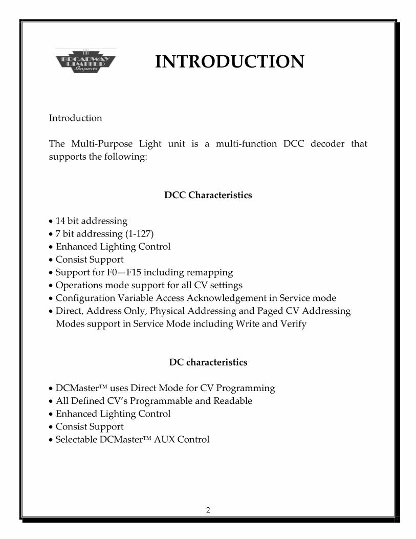
System CVs Table
CV Description Initial Yours 1 Primary Address 3 7 Manufacturer Version ? 8 Manufacturer ID 38 17 Extended Address MSB 192 18 Extended Address LSB 128 19 Consist Address 0 21 Consist Functions Type 0 255 22 Consist Functions Type1 255 29 Configuration Bits 4 33 L1 Control Varies 34 L2 Control Varies 35 L3 Control Varies 36 L4 Control Varies 37 L5 Control Varies 63 Lights Power-Up Control Varies 64 AUX Control Varies
3
Decimal to Binary Primer
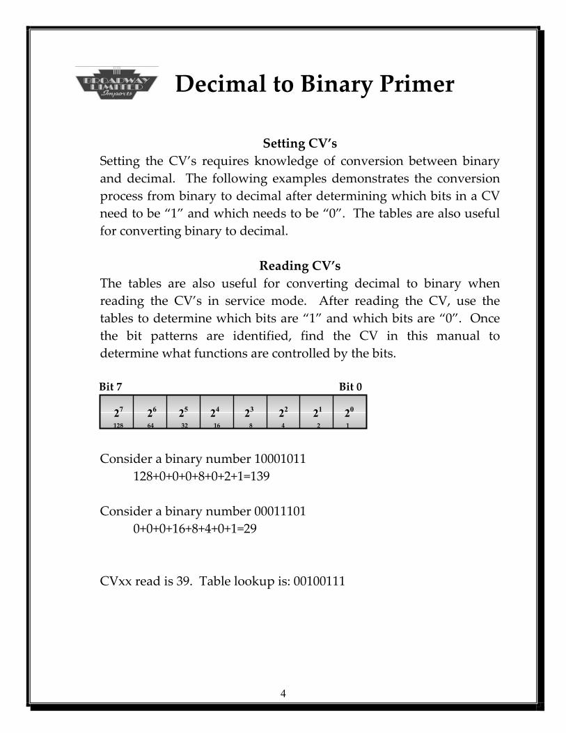
Setting CV’s Setting the CV’s requires knowledge of conversion between binary and decimal. The following examples demonstrates the conversion process from binary to decimal after determining which bits in a CV need to be “1” and which needs to be “0”. The tables are also useful for converting binary to decimal.
Reading CV’s The tables are also useful for converting decimal to binary when reading the CV’s in service mode. After reading the CV, use the tables to determine which bits are “1” and which bits are “0”. Once the bit patterns are identified, find the CV in this manual to determine what functions are controlled by the bits.
Bit 7 Bit 0 27 26 25 24 23 22 21 20
128 64 32 16 8 4 2 1
Consider a binary number 10001011 128+0+0+0+8+0+2+1=139
Consider a binary number 00011101 0+0+0+16+8+4+0+1=29
CVxx read is 39. Table lookup is: 00100111
4
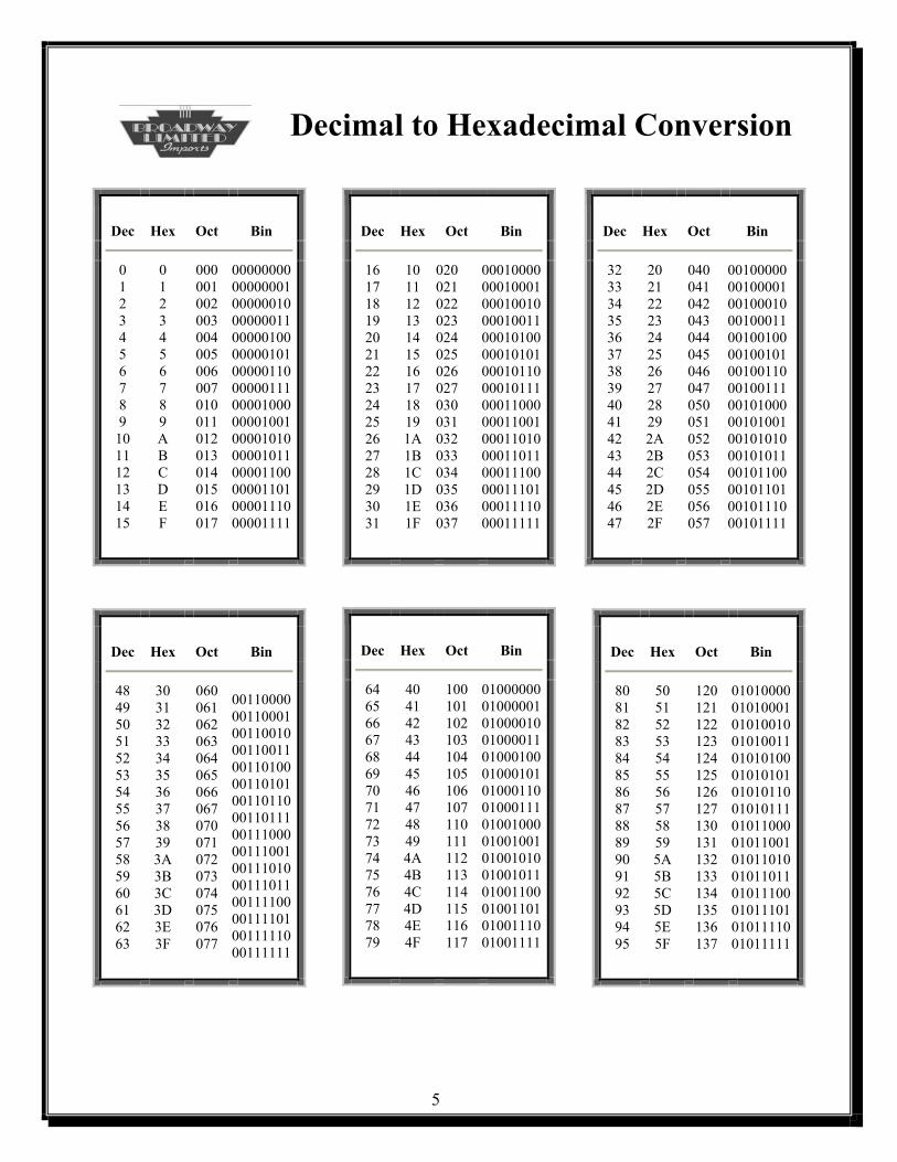
Decimal to Hexadecimal Conversion
5
Dec
Hex
Oct
Bin
0 1 2 3 4 5 6 7 8 9
10 11 12 13 14 15
0 1 2 3 4 5 6 7 8 9 A B C D E F
000 001 002 003 004 005 006 007 010 011 012 013 014 015 016 017
00000000 00000001 00000010 00000011 00000100 00000101 00000110 00000111 00001000 00001001 00001010 00001011 00001100 00001101 00001110 00001111
Dec
Hex
Oct
Bin
16171819202122232425262728293031
10 11 12 13 14 15 16 17 18 19 1A1B 1C 1D1E 1F
020 021 022 023 024 025 026 027 030 031 032 033 034 035 036 037
00010000000100010001001000010011000101000001010100010110000101110001100000011001000110100001101100011100000111010001111000011111
Dec
Hex
Oct
Bin
32333435363738394041424344454647
20 21 22 23 24 25 26 27 28 29 2A 2B 2C 2D 2E 2F
040 041 042 043 044 045 046 047 050 051 052 053 054 055 056 057
00100000001000010010001000100011001001000010010100100110001001110010100000101001001010100010101100101100001011010010111000101111
Dec
Hex
Oct
Bin
48 49 50 51 52 53 54 55 56 57 58 59 60 61 62 63
30 31 32 33 34 35 36 37 38 39 3A 3B 3C 3D 3E 3F
060 061 062 063 064 065 066 067 070 071 072 073 074 075 076 077
00110000 00110001 00110010 00110011 00110100 00110101 00110110 00110111 00111000 00111001 00111010 00111011 00111100 00111101 00111110 00111111
Dec
Hex
Oct
Bin
64656667686970717273747576777879
40 41 42 43 44 45 46 47 48 49 4A4B 4C 4D4E 4F
100101102103104105106107110111112113114115116117
01000000010000010100001001000011010001000100010101000110010001110100100001001001010010100100101101001100010011010100111001001111
Dec
Hex
Oct
Bin
80 81 82 83 84 85 86 87 88 89 90 91 92 93 94 95
50 51 52 53 54 55 56 57 58 59 5A 5B 5C 5D 5E 5F
120 121 122 123 124 125 126 127 130 131 132 133 134 135 136 137
01010000010100010101001001010011010101000101010101010110010101110101100001011001010110100101101101011100010111010101111001011111
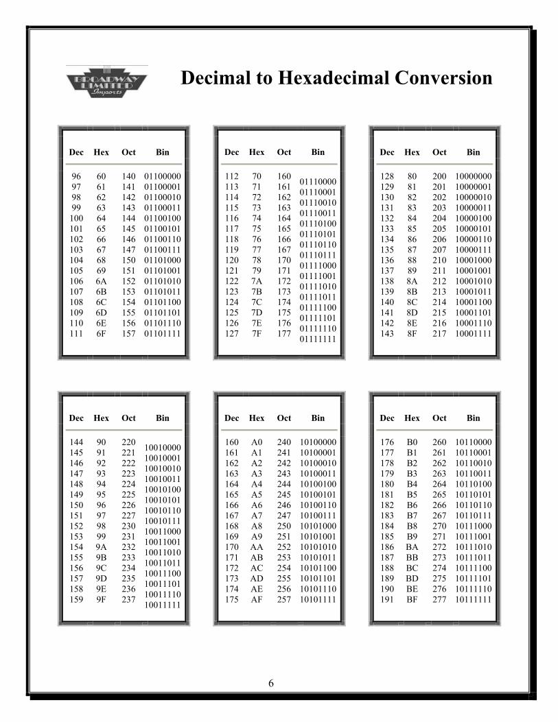
Decimal to Hexadecimal Conversion
6
Dec
Hex
Oct
Bin
112113114115116117118119120121122123124125126127
70 71 72 73 74 75 76 77 78 79 7A7B 7C 7D7E 7F
160161162163164165166167170171172173174175176177
01110000011100010111001001110011011101000111010101110110011101110111100001111001011110100111101101111100011111010111111001111111
Dec
Hex
Oct
Bin
128 129 130 131 132 133 134 135 136 137 138 139 140 141 142 143
80 81 82 83 84 85 86 87 88 89 8A 8B 8C 8D 8E 8F
200 201 202 203 204 205 206 207 210 211 212 213 214 215 216 217
10000000100000011000001010000011100001001000010110000110100001111000100010001001100010101000101110001100100011011000111010001111
Dec
Hex
Oct
Bin
96 97 98 99
100 101 102 103 104 105 106 107 108 109 110 111
60 61 62 63 64 65 66 67 68 69 6A 6B 6C 6D 6E 6F
140 141 142 143 144 145 146 147 150 151 152 153 154 155 156 157
01100000 01100001 01100010 01100011 01100100 01100101 01100110 01100111 01101000 01101001 01101010 01101011 01101100 01101101 01101110 01101111
Dec
Hex
Oct
Bin
144 145 146 147 148 149 150 151 152 153 154 155 156 157 158 159
90 91 92 93 94 95 96 97 98 99 9A 9B 9C 9D 9E 9F
220 221 222 223 224 225 226 227 230 231 232 233 234 235 236 237
10010000 10010001 10010010 10010011 10010100 10010101 10010110 10010111 10011000 10011001 10011010 10011011 10011100 10011101 10011110 10011111
Dec
Hex
Oct
Bin
160161162163164165166167168169170171172173174175
A0A1A2A3A4A5A6A7A8A9AAABACADAEAF
240241242243244245246247250251252253254255256257
10100000101000011010001010100011101001001010010110100110101001111010100010101001101010101010101110101100101011011010111010101111
Dec
Hex
Oct
Bin
176 177 178 179 180 181 182 183 184 185 186 187 188 189 190 191
B0 B1 B2 B3 B4 B5 B6 B7 B8 B9 BA BB BC BD BE BF
260 261 262 263 264 265 266 267 270 271 272 273 274 275 276 277
10110000101100011011001010110011101101001011010110110110101101111011100010111001101110101011101110111100101111011011111010111111
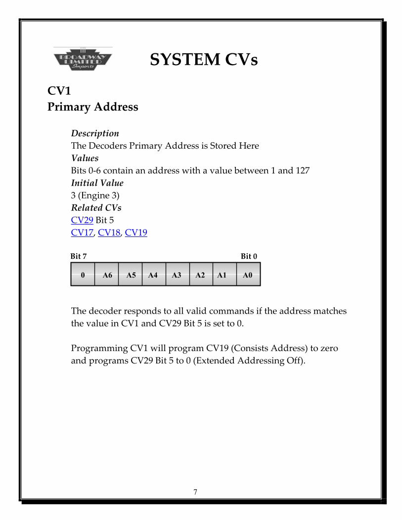
SYSTEM CVs CV1 Primary Address Description The Decoders Primary Address is Stored Here Values Bits 0-6 contain an address with a value between 1 and 127 Initial Value 3 (Engine 3) Related CVs CV29 Bit 5 CV17, CV18, CV19 Bit 7 Bit 0 0 A6 A5 A4 A3 A2 A1 A0
The decoder responds to all valid commands if the address matches the value in CV1 and CV29 Bit 5 is set to 0. Programming CV1 will program CV19 (Consists Address) to zero and programs CV29 Bit 5 to 0 (Extended Addressing Off).
7
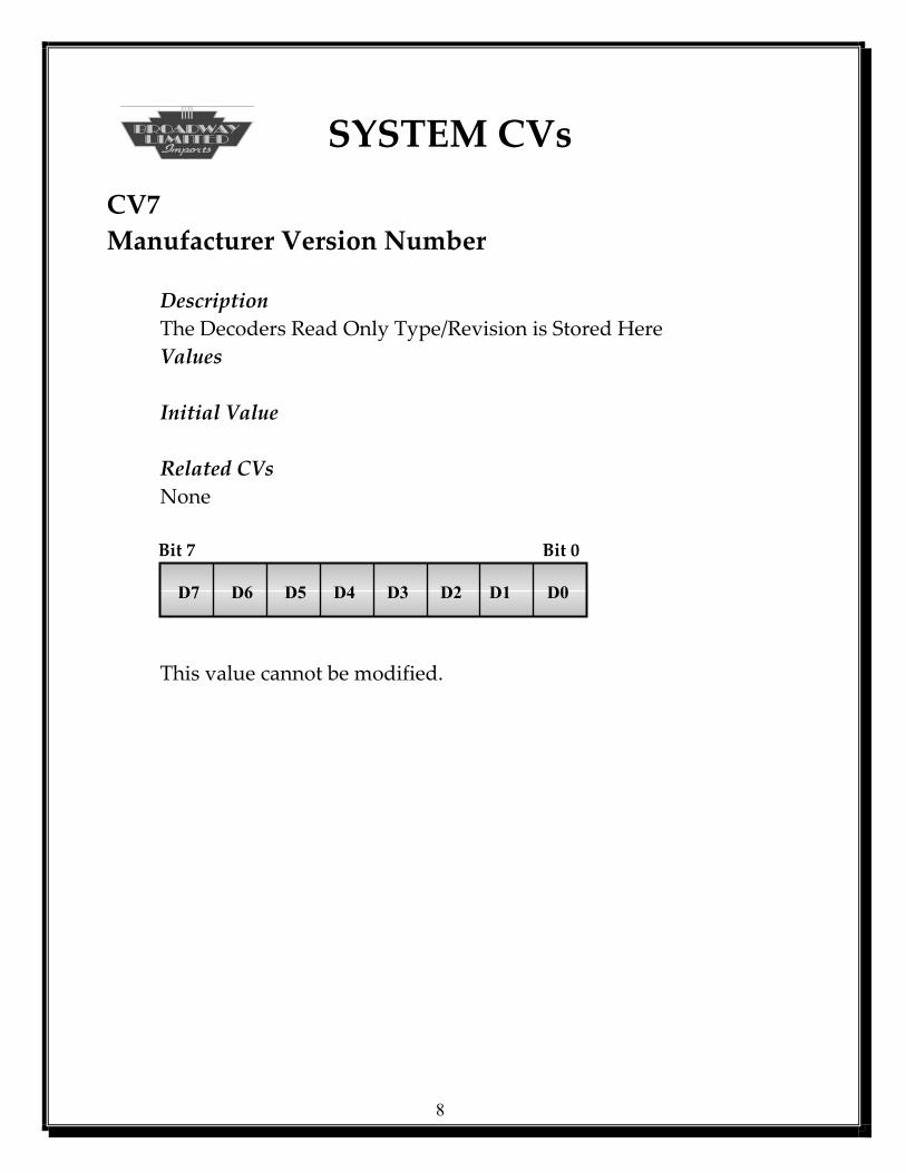
SYSTEM CVs CV7 Manufacturer Version Number Description The Decoders Read Only Type/Revision is Stored Here Values Initial Value Related CVs None Bit 7 Bit 0 D7 D6 D5 D4 D3 D2 D1 D0
This value cannot be modified.
8
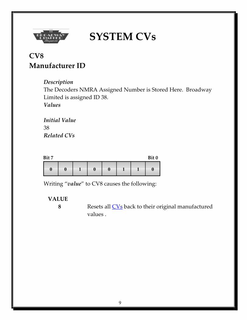
SYSTEM CVs CV8 Manufacturer ID Description
The Decoders NMRA Assigned Number is Stored Here. Broadway Limited is assigned ID 38.
Values Initial Value 38 Related CVs Bit 7 Bit 0 0 0 1 0 0 1 1 0 Writing “value” to CV8 causes the following: VALUE
8 Resets all CVs back to their original manufactured values .
9
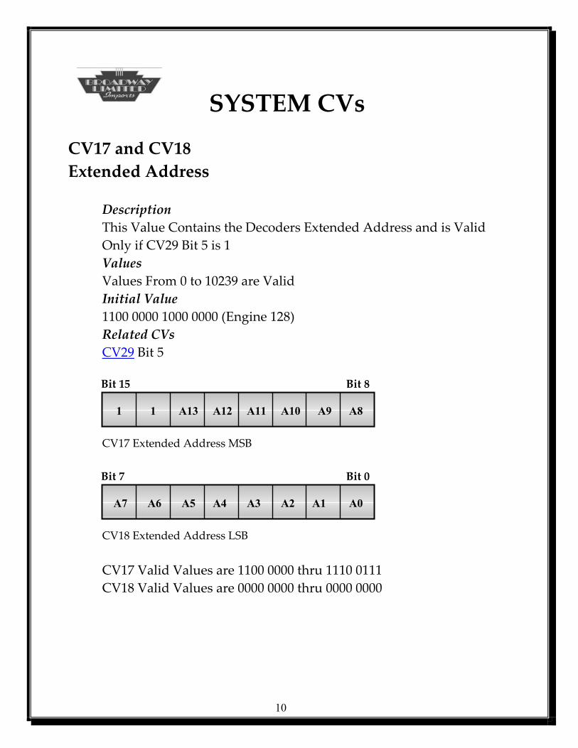
SYSTEM CVs CV17 and CV18 Extended Address Description
This Value Contains the Decoders Extended Address and is Valid Only if CV29 Bit 5 is 1
Values Values From 0 to 10239 are Valid Initial Value 1100 0000 1000 0000 (Engine 128) Related CVs CV29 Bit 5 Bit 15 Bit 8 1 1 A13 A12 A11 A10 A9 A8 CV17 Extended Address MSB Bit 7 Bit 0 A7 A6 A5 A4 A3 A2 A1 A0 CV18 Extended Address LSB
CV17 Valid Values are 1100 0000 thru 1110 0111 CV18 Valid Values are 0000 0000 thru 0000 0000
10
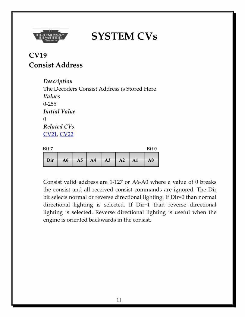
SYSTEM CVs CV19 Consist Address Description The Decoders Consist Address is Stored Here Values 0-255 Initial Value 0 Related CVs CV21, CV22 Bit 7 Bit 0 Dir A6 A5 A4 A3 A2 A1 A0
Consist valid address are 1-127 or A6-A0 where a value of 0 breaks the consist and all received consist commands are ignored. The Dir bit selects normal or reverse directional lighting. If Dir=0 than normal directional lighting is selected. If Dir=1 than reverse directional lighting is selected. Reverse directional lighting is useful when the engine is oriented backwards in the consist.
11
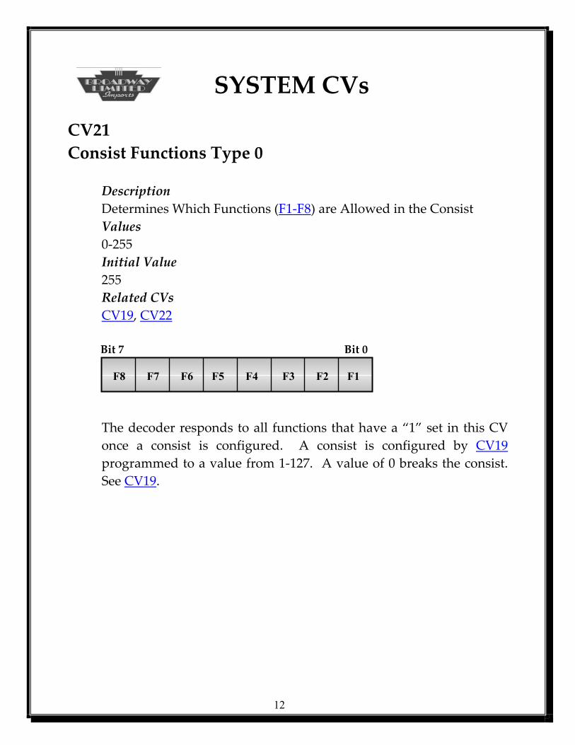
SYSTEM CVs CV21 Consist Functions Type 0 Description Determines Which Functions (F1-F8) are Allowed in the Consist Values 0-255 Initial Value 255 Related CVs CV19, CV22 Bit 7 Bit 0 F8 F7 F6 F5 F4 F3 F2 F1
The decoder responds to all functions that have a “1” set in this CV once a consist is configured. A consist is configured by CV19 programmed to a value from 1-127. A value of 0 breaks the consist. See CV19.
12
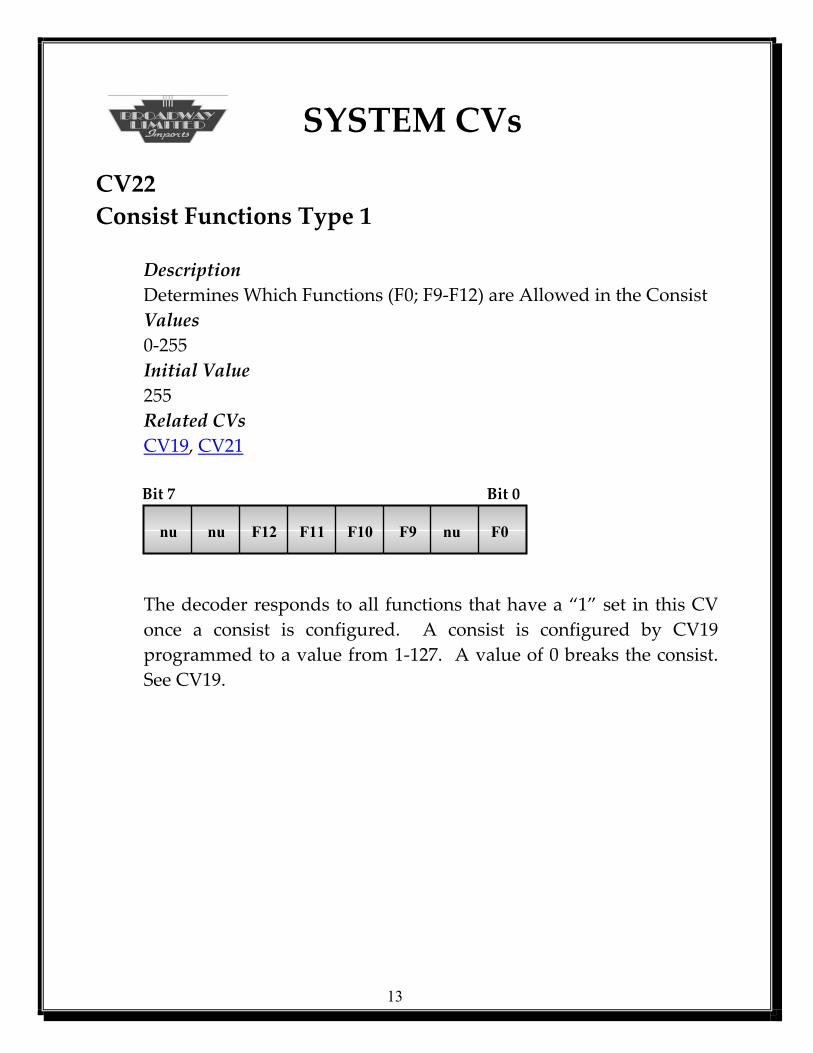
SYSTEM CVs CV22 Consist Functions Type 1 Description Determines Which Functions (F0; F9-F12) are Allowed in the Consist Values 0-255 Initial Value 255 Related CVs
CV19, CV21 Bit 7 Bit 0 nu nu F12 F11 F10 F9 nu F0
The decoder responds to all functions that have a “1” set in this CV once a consist is configured. A consist is configured by CV19 programmed to a value from 1-127. A value of 0 breaks the consist. See CV19.
13
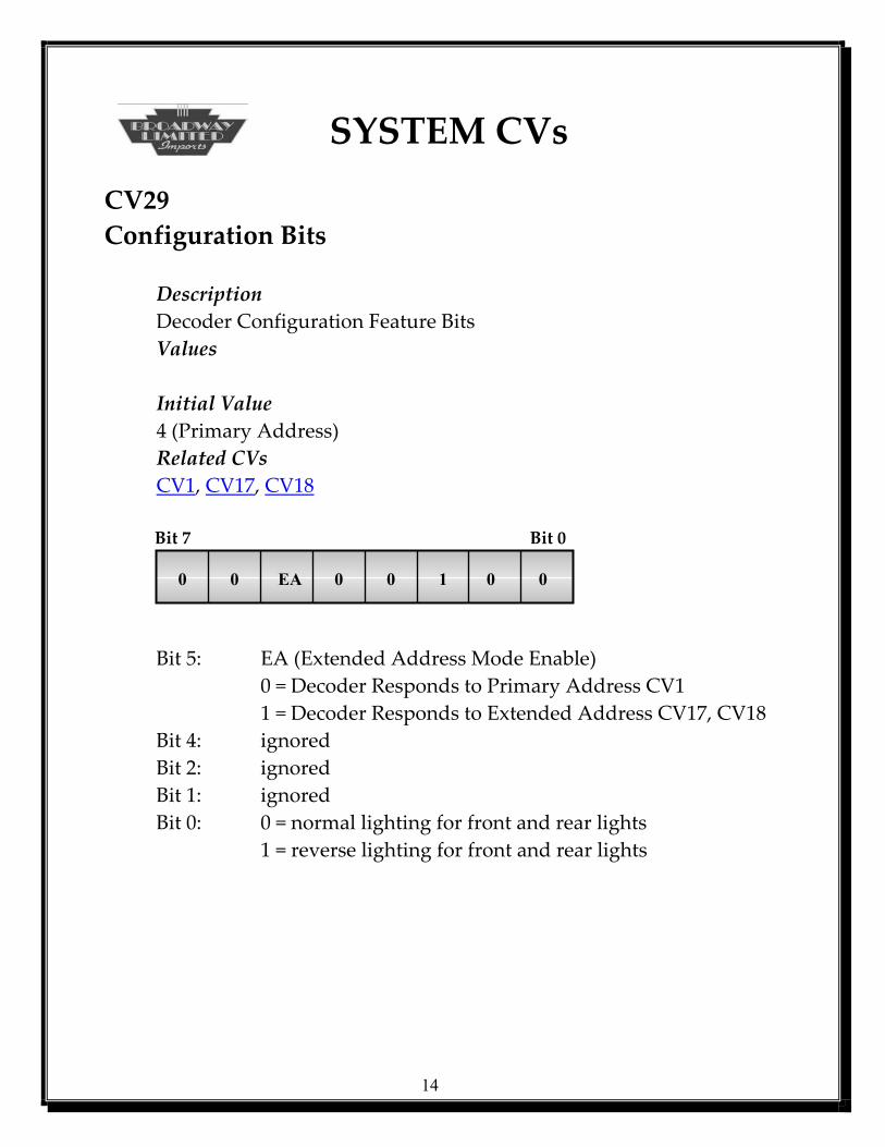
SYSTEM CVs CV29 Configuration Bits Description Decoder Configuration Feature Bits Values Initial Value 4 (Primary Address) Related CVs CV1, CV17, CV18 Bit 7 Bit 0 0 0 EA 0 0 1 0 0
Bit 5: EA (Extended Address Mode Enable) 0 = Decoder Responds to Primary Address CV1 1 = Decoder Responds to Extended Address CV17, CV18 Bit 4: ignored Bit 2: ignored Bit 1: ignored
Bit 0: 0 = normal lighting for front and rear lights 1 = reverse lighting for front and rear lights
14
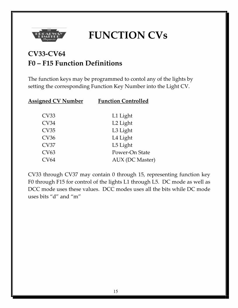
FUNCTION CVs CV33-CV64 F0 – F15 Function Definitions The function keys may be programmed to contol any of the lights by setting the corresponding Function Key Number into the Light CV. Assigned CV Number Function Controlled
CV33 L1 Light CV34 L2 Light CV35 L3 Light CV36 L4 Light CV37 L5 Light
CV63 Power-On State CV64 AUX (DC Master) CV33 through CV37 may contain 0 through 15, representing function key F0 through F15 for control of the lights L1 through L5. DC mode as well as DCC mode uses these values. DCC modes uses all the bits while DC mode uses bits “d” and “m”
15
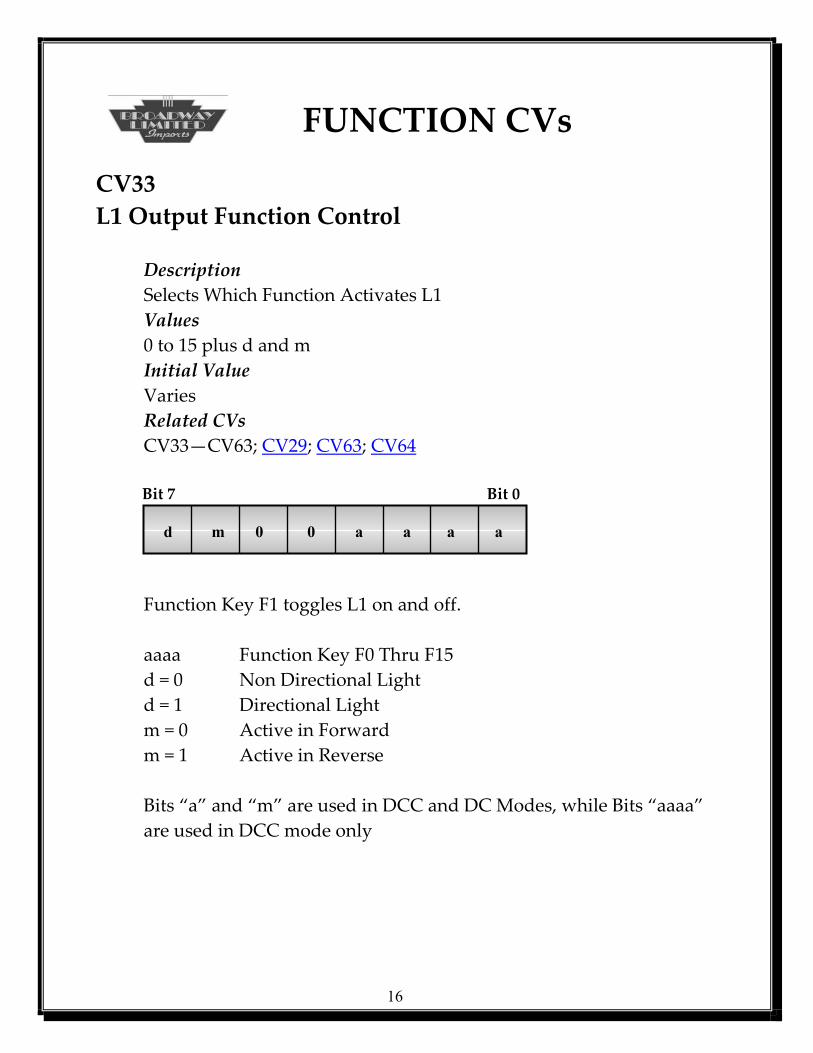
FUNCTION CVs CV33 L1 Output Function Control Description Selects Which Function Activates L1 Values 0 to 15 plus d and m Initial Value Varies Related CVs CV33—CV63; CV29; CV63; CV64 Bit 7 Bit 0 d m 0 0 a a a a
Function Key F1 toggles L1 on and off. aaaa Function Key F0 Thru F15
d = 0 Non Directional Light d = 1 Directional Light m = 0 Active in Forward m = 1 Active in Reverse
Bits “a” and “m” are used in DCC and DC Modes, while Bits “aaaa” are used in DCC mode only
16
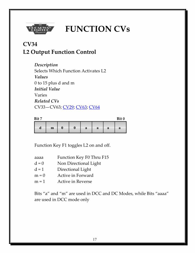
FUNCTION CVs CV34 L2 Output Function Control Description Selects Which Function Activates L2 Values 0 to 15 plus d and m Initial Value Varies Related CVs CV33—CV63; CV29; CV63; CV64 Bit 7 Bit 0 d m 0 0 a a a a
Function Key F1 toggles L2 on and off. aaaa Function Key F0 Thru F15
d = 0 Non Directional Light d = 1 Directional Light m = 0 Active in Forward m = 1 Active in Reverse Bits “a” and “m” are used in DCC and DC Modes, while Bits “aaaa” are used in DCC mode only
17

FUNCTION CVs CV35 L3 Output Function Control Description Selects Which Function Activates L3 Values 0 to 15 plus d and m Initial Value Varies Related CVs CV33—CV63; CV29; CV63; CV64 Bit 7 Bit 0 d m 0 0 a a a a
Function Key F1 toggles L3 on and off. aaaa Function Key F0 Thru F15
d = 0 Non Directional Light d = 1 Directional Light m = 0 Active in Forward m = 1 Active in Reverse Bits “a” and “m” are used in DCC and DC Modes, while Bits “aaaa” are used in DCC mode only
18

FUNCTION CVs CV36 L4 Output Function Control Description Selects Which Function Activates L4 Values 0 to 15 plus d and m Initial Value Varies Related CVs CV33—CV63; CV29; CV63; CV64 Bit 7 Bit 0 d m 0 0 a a a a
Function Key F1 toggles L4 on and off. aaaa Function Key F0 Thru F15
d = 0 Non Directional Light d = 1 Directional Light m = 0 Active in Forward m = 1 Active in Reverse Bits “a” and “m” are used in DCC and DC Modes, while Bits “aaaa” are used in DCC mode only
19

FUNCTION CVs CV37 L5 Output Function Definition Description Selects Which Function Activates L5 Values 0 to 15 plus d and m Initial Value Varies Related CVs CV33—CV63; CV29; CV63; CV64 Bit 7 Bit 0 0 0 0 0 a a a a
Function Key F1 toggles L5 on and off. aaaa Function Key F0 Thru F15 d = 0 Non Directional Light d = 1 Directional Light m = 0 Active in Forward m = 1 Active in Reverse Bits “a” and “m” are used in DCC and DC Modes, while Bits “aaaa” are used in DCC mode only
20
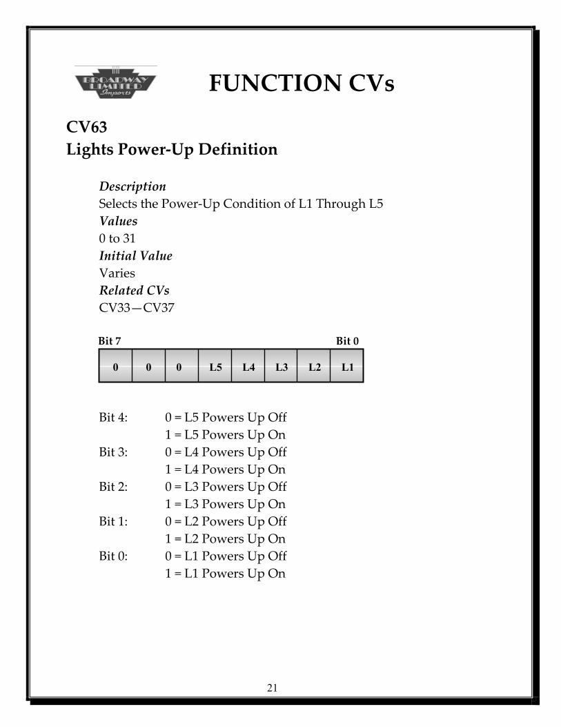
FUNCTION CVs CV63 Lights Power-Up Definition Description Selects the Power-Up Condition of L1 Through L5 Values 0 to 31 Initial Value Varies Related CVs CV33—CV37 Bit 7 Bit 0 0 0 0 L5 L4 L3 L2 L1
Bit 4: 0 = L5 Powers Up Off 1 = L5 Powers Up On Bit 3: 0 = L4 Powers Up Off 1 = L4 Powers Up On Bit 2: 0 = L3 Powers Up Off 1 = L3 Powers Up On Bit 1: 0 = L2 Powers Up Off 1 = L2 Powers Up On Bit 0: 0 = L1 Powers Up Off
1 = L1 Powers Up On
21
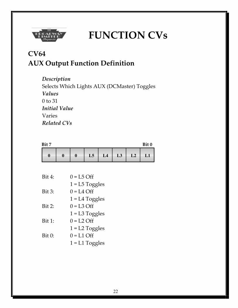
FUNCTION CVs CV64 AUX Output Function Definition Description Selects Which Lights AUX (DCMaster) Toggles Values 0 to 31 Initial Value Varies Related CVs Bit 7 Bit 0 0 0 0 L5 L4 L3 L2 L1
Bit 4: 0 = L5 Off 1 = L5 Toggles Bit 3: 0 = L4 Off 1 = L4 Toggles Bit 2: 0 = L3 Off 1 = L3 Toggles Bit 1: 0 = L2 Off 1 = L2 Toggles Bit 0: 0 = L1 Off
1 = L1 Toggles
22
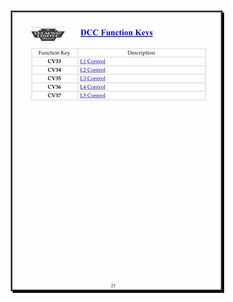
DCC Function Keys
Function Key Description CV33 L1 Control CV34 L2 Control CV35 L3 Control CV36 L4 Control CV37 L5 Control
23
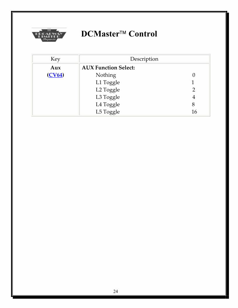
DCMaster Control
Key Description Aux
(CV64) AUX Function Select:
Nothing 0 L1 Toggle 1 L2 Toggle 2 L3 Toggle 4 L4 Toggle 8 L5 Toggle 16
24
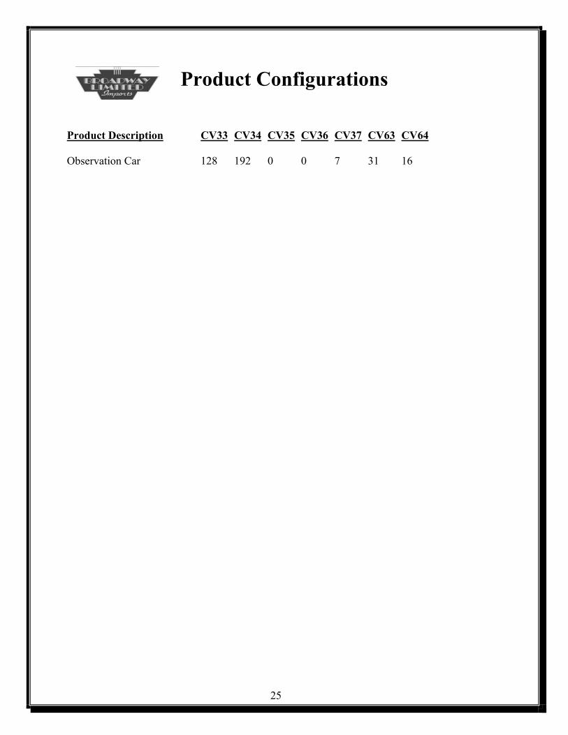
Product Configurations Product Description CV33 CV34 CV35 CV36 CV37 CV63 CV64 Observation Car 128 192 0 0 7 31 16
25