VENTS D EN AXIAL FANS user's manual VENTS D1 AXIALLÜFTER ...

A Proposal for NewPresentations
MULTI PROJECTOR
User’s Manual
Head office : 3-20-1 Nishi Shinbashi, Minato-ku, Tokyo, Japan
Technical Support Information
Instrument Service Center, Electronics Equipment Division 2-28-2 Hongo, Seya-ku, Yokohama, Japan
Zip code : 246-0015 Tel : +81-45-304-8233
To customers : Enter the name and date of the store where you purchased thisproduct. This information will be useful when you ask your dealerfor repair.
• Date of Purchase (year, month, day)
• Store of Purchase
Telephone Number : ( )
7000562-R01Eq
NIPPON AVIONICS CO.,LTD.
Cover1-4 (B4) 04.7.29, 11:41 AM1

2
Thank you for purchasing the Nippon Avionics MP-700 Multi Projector.Please read this manual carefully in order to use the projector properly.After reading this, please keep it in a safe place together with the warranty sheet.
Features
• Three handy features in a single body. The projector for the multimedia age1. Documents, catalogs and other printed matter can be projected directly from
the scanner. This frees the user from the need to make OHP film inserts foreach document.
2. Personal computer screens can be projected. This allows the user to makedetailed presentations using information on a personal computer.
3. Videos and DVD images can be projected as they are. This aids the user inmaking visually appealing presentations.
• Easy-to-understand and simple operationProjection of printed matter, personal computer screens and video images canbe selected at the push of a button.
• High cost effective resource-saving designOHP film inserts no longer need to be made, which saves wasted time andexpense.
• Expressive color imagesThe projector is equipped with a high-resolution 2 million pixel single-array colorCCD camera. This allows subtle midtones in color documents to be reproducedfaithfully and sharp as projected images in full color (16,770,000 colors).
• Enlarged display without changing the size of the projected imageWhen projecting documents such as catalogs and word-processor documentscontaining small text that have not been made specially for presentations, thedocument can be enlarged without changing the size of the projected image foreasier viewing.
• Provided with display functions for compressed or enlarged PC screenScreens of resolution more than 1024 x 768 dots are displayed compressed to1024 x 768 dots without any loss in character quality. Such as 640 x 480resolution screens can also be enlarged to 1024 x 768 dots.
• Provided with a CF (CompactFlashTM) card slotStore OHP images on the CF card and read OHP images from the CF card to beprojected.
About TrademarksIBM and DOS/V are trademarks or registered trademarks of International BusinessMachines Corporation.Macintosh and Power Book are trademarks of Apple Computer Inc.Windows is a trademark of U.S. Microsoft Corporation.
Cover2.pmd 04.7.29, 11:42 AM2
3
Warnings and Safety Precautions
Warning SymbolsTo alert the user to important safety precautions, the following symbols are usedin this manual and on the product. Make sure you understand what these sym-bols mean before operating the projector.
WARNING : Death or serious injury may result if this warning is ignored.
CAUTION : Injury or damage to the equipment may result if this warning isignored.
NOTE : This indicates an item that you should take care of when handlingyour projector.
: This symbol alerts the user to high voltage that could cause electricshock.
Safety PrecautionsWARNING
• If a fault occurs:• If you detect smoke, or a strange smell or sound, immediately disconnect the
power cord.It is dangerous to continue using the projector after a fault occurs. Return theprojector to the dealer where it was purchased for repair.
• Avoid placing the projector near dangerous substances.• Make sure that no metallic or flammable material can get into the projector
through the air vents.• Do not place any objects containing water on top of or next to the projector.
• If foreign matter gets inside the projector:• If foreign matter such as water or metal gets inside, immediately disconnect
the power cord.It is dangerous to continue using the projector when foreign matter getsinside. Return the projector to the dealer where it was purchased for servic-ing.
• Do not remove the cabinet.• Do not remove the cabinet. There are high-voltage components inside and
touching these parts could cause electric shock, or damage the equipment.
• Handle the power cable safely.• Do not place any heavy objects on top of the power cord.
Damage to the power cord can cause wire breakage, fire, or electric shock.• Do not pull the power cord when disconnecting the power plug.
Pulling the cable may break the wires or cause fire or electric shock. Alwayshold the plug itself when pulling it out of the power outlet.
• Do not damage the power cord. If the power cord is damaged (e.g. the coreis exposed or cut), contact the sales office of purchase.(charged) It couldcause fire or electric shock to continue using the damaged power cord.
Cha.01 04.7.29, 11:43 AM3

4
• Do not look through the lens.• Do not look through the lens into the projector during operation. The powerful
rays passing through the lens could damage the eyes.
• Do not put the projector in unstable places.• Do not put the projector in unstable places such as on unstable desks or
slopes.Doing so could cause the projector to drop or turn over, resulting in injury.
• Do not use any voltages other than specified.• Do not use any voltages other than specified. Doing so could cause fire or
electric shock.
• Do not disassemble the alkaline batteries• Do not short-circuit, disassemble, or burn the alkaline batteries.
Doing so could cause the alkaline solution to leak, Which could cause eyeinjury, as well as cause a fire or damage the surrounding area due to heat orexplosion. If the alkaline solution touches skin or clothes, wash them withclean water. If it get into eyes, immediately wash them with clean water andsee a doctor.
• Do not bump the glass surface• Do not bump the glass surface over the scanner. Doing so may break the
glass, resulting in injury.
• Do not touch the air vents or lamp cover• The air vents, lamp cover, and peripheral surfaces may be hot during opera-
tion or just after the light is turned off.Do not touch those for a long time.
• Do not block the lens front• Do not block the lens front during operation.
The powerful rays passing through the lens may cause fire or burns if you putanything in front of the lens or block the lens with your hand during operation.
CAUTION
• Installation• Avoid installing the projector in places where it may be exposed to:
- Strong vibrations- Soot or steam- Direct sunlight or near a heater (35˚C/95˚F or higher)- High humidity or dust- Extreme cold (0˚C/32˚F or lower)- Strong magnetic or electric field generated from a nearby appliance- Wobbling on an unstable surface
• Do not block the air vents.• Do not block the air vents with cloth or an object.
When you put anything around the unit, be sure to ensure a space of 10 cm/4inches or more between the unit and the air vent. Be sure to prevent paper orcloth from blocking the air vent at the bottom of the unit. If blocked, theinternal temperature may increase, resulting in malfunctions.
• Do not bump the projector.• Avoid bumping the projector when moving or handling. Shocks can cause
damage.
Cha.01 04.7.29, 11:43 AM4

5
• Care of the projector• To prevent risk of accidents, always pull out the power plug before cleaning
the projector.• Clean the lens surface with a commercial blower or lens cleaning paper.
Wiping with tissue paper or a handkerchief can damage the lens.• To clean the cabinet, operation panel, and glass surface, wipe gently with a
soft cloth. For particularly dirty spots, soak the cloth in a neutral detergentmixed in water, wring out well and wipe off the dirt, then use a dry cloth towipe dry.
• Do not wipe the projector with any volatile solvent such as benzine or thinner.Solvents can cause surface deformation or flaking of the paint.If using an impregnated cloth, follow the instructions.
• Avoid scratching the glass surface.• Take care not to scratch the glass surface of the scanner with hard or pointed
objects.Scratches on the glass may distort the projected image.
• Batteries• When inserting batteries in the remote control, note the polarity (plus and
minus signs) and insert correctly as indicated. Inserting a battery in a wrongdirection can cause rupture or leakage, and could result in fire and injury orsoil the surrounding area.
• Do not use batteries other than the type specified for the equipment. Do notuse a new battery and an old battery together. Incorrect battery usage couldresult in rupture or leakage, and could cause fire and injury.
• Do not heat, break open, burn, or immerse the batteries. Battery rupture orleakage could cause fire and injury.
• Servicing and cleaning• Have the internal components cleaned by a retailer about once a year. There
is a risk of fire or faulty operation if the inside of the projector gets dusty andis not cleaned for a long time. For best results, the projector should beserviced before the wet season brings damp conditions. Cleaning chargesare at the discretion of the retailer.
• If not using the projector for a long period:• If you do not plan to use the projector for a long time, pull out the power plug
for safety.
• Disposal• Follow the recommendations of your local authority when disposing of the
projector.
• Transporting the projector• Use the special packaging when transporting the projector. The manufac-
turer. cannot accept responsibility in the event of damage or accident if otherpackaging is used.
• Use the special packaging no more than two times. Repeated usage reducesthe shock absorbency of the packaging and can lead to damage or accident.
• Contact the retailer if you require new packaging.
• Lamp implosion• An AC type New Super High pressure lamp is used in this projector and it is
rare for the lamp to explode during use. The lamp is also designed to forciblyturn off because there is a high possibility that the lamp breaks if it is usedbeyond the lamp usage of 1500 hours (Refer to pages 64 and 65).
Cha.01 04.7.29, 11:43 AM5

6
• Note the following things• A noise occurs because the internal pressure of the New Super High pres-
sure lamp gets extremely high.The unit is designed so that no pieces of glass come out of it when the lampexplodes.
• However, the gas inside of the lamp can escape and looks like white smoke.It will not cause any fire.
• Remedy• If a lamp explodes in a product, there will be pieces of lamp inside. Do not
replace the lamp. Return the product to the sales office or agent of purchase.Even though the lamp has exploded, never try to replace the lamp by your-self. The lamp pieces may cause injury.
• Replacing the lamp• Be sure to turn the lamp off and disconnect the power cord when the fan
stops, and wait an hour or more before replacing the lamp.Replacing the lamp during operation or just after the power is turned off maycause burns due to heat.Refer to “Lamp Unit Replacement” on page 64 for the procedure.
• Replacing / cleaning the air filter• Be sure to pull out the power plug when the cooling fan stops before remov-
ing the air filter.Removing the air filter while the cooling fan is rotating could cause a burninjury. Refer to “Cleaning the Air Filter” on page 66 for the procedure.
• Avoiding malfunctions and accidents• Adjust the Adjustable feet to keep the projector horizontal.
Using the projector in a tilted status could cause injury when it turns over.Refer to “Adjusting the Tilt” on page 18 or the adjusting procedure.
• Do not disassemble the manganese batteries• Do not short-circuit, disassemble, or burn the manganese batteries. Doing so
could cause the batteries to generate heat or explode due to the leakedsolution, resulting in fire, injury, or damages to the surrounding area.
• Do not do the followings• Do not put anything heavy on the projector.• Do not step on the projector, rack, or stand. Do not hold or hang on the
projector.Doing so could cause the projector to turn over or break, resulting in injury.Especially be careful if small kids are near.
• Do not use the rack unless the casters are locked when placing the projectoron a rack with casters.Doing so may cause the projector to move or turn over, resulting in injury.
• Do not turn the lamp on/off within one minute after it is turned off/on. Ex-tremely high voltage is generated in the lamp just after it is turned on. Turningthe lamp on/off too frequently could cause the lamp to deteriorate or break,resulting in malfunctions of the projector.
• Do not project an image with the lens cap attached.
• Moving the projector• Be sure careful of the glass surface when moving the projector while holding
the handles with both hands.• If not inserted fully, the material cover may get loose and fall off while you
carry it.
Cha.01 04.7.29, 11:43 AM6

7
• Care of the power cord and plug• Do not put the power cord near a heater.
Doing so could cause the sheath of the cable to melt down, resulting in fire orelectric shock.
• Do not connect or disconnect the power cord with wet hands. Doing so couldcause electric shock.
• Be sure to pull out the power cord and disconnect any cable connectionsbetween units and release the anti-theft lock before moving the projector.Moving the projector with cables connected may cause fire or electric shock ifthe cables are damaged.
• If you do not plan to use the projector for a long time, disconnect the powercord for safety.
• DO NOT REMOVE ANY SCREWS except the lamp cover screw and two lampunit screws. You could receive an electric shock.
Cha.01 04.7.29, 11:43 AM7

8
Contents
Part Names and Functions ................................................................9Projector .......................................................................................................................9
Terminal Panel ....................................................................................................... 11Buttons and Indicator Lights .................................................................................. 12
Remote Control ........................................................................................................... 15Remote Control Operations ................................................................................... 17Battery Replacement ............................................................................................. 17
How to Install the Projector .............................................................18Installation Sequence ............................................................................................ 18Adjusting the Tilt .................................................................................................... 18Projection Distance and Projected Image Size...................................................... 19Typical Installation ................................................................................................. 20Compensating Keystone........................................................................................ 21
Connecting to a Personal Computer ...............................................22Connecting to a Personal Computer...................................................................... 22About RGB Video Output ....................................................................................... 24When Images on the Personal Computer Screen are not Projected ..................... 25Input Signal Compatibility Table (PC video input terminal) .................................... 26Connecting to a Video Source or DVD Player ....................................................... 29
Basic Operation ...............................................................................30Preparation ............................................................................................................ 30Basic Operations in the OHP Mode ....................................................................... 31Basic Operation of PC or Video Input .................................................................... 38How to Quit ............................................................................................................ 42Performing Various Adjustments ............................................................................ 43
Menu Structure ................................................................................................. 43Description of Menu Items ................................................................................ 44
Basic Operation ..................................................................................................... 48Quick Menu............................................................................................................ 52
Description of Menu Items ................................................................................ 52Saving OHP ........................................................................................................... 55
Save images to the CF Card ............................................................................ 55Display Images Saved on the CF Card ............................................................ 56Delete Images Saved on the CF Card .............................................................. 58Initialize the CF Card ........................................................................................ 59Use Images Saved on the CF Card as Wallpaper to Mute the Projected Image ........ 60
Maintenance ....................................................................................62Fault Protection...................................................................................................... 62Lamp Unit Replacement ........................................................................................ 64Cleaning the Air Filter ............................................................................................ 66
Troubleshooting ...............................................................................67
Warranty & Repair Service ..............................................................69
Specifications ..................................................................................70
* Company names and product names herein are trademarks and registered trademarks of thosecompanies.
Cha.01 04.7.29, 11:43 AM8

9
Part Names and Functions
Part Names and Functions
Projector
Operation panelButtons for operating the projector are located here.See page 12.
Terminal PanelConnection terminals for a PC or video source are located here.See page 11.
Tilt Adjustment ButtonsPress this to adjust the adjustable feet. See page 18.
Adjustable Feet
Adjustable FeetThese feet are for adjusting the tilt angle as well as the left and right balance of the projected image. Turning them counterclockwise raises the main unit, and turning them clockwise lowers the main unit.See page 18.
Zoom AdjusterTurn this ring to adjust the size of the projected image. See page 31.
Materials CoverThe scanner and printed matter is located under this cover. See page 32.
Handle
Remote Control Sensor
Adjustable Feet
Projection LensImages are projected through this lens.* Be sure to remove the lens cap when
projecting images.
Focus AdjusterTurn this to adjust the focus. See page 31.
Air Vent A (air filter) (bottom of main unit)
Air is taken in through this vent. An air filter is provided to prevent dust from getting inside the projector.See page 66.
Cha.02 04.7.29, 11:44 AM9

10
NOTE
About the anti-theft lock The anti-theft lock is compatible with smart cable lock and other security wires.Contact the following for more information about the products.© 1998 Kensington Technology Group.
Kensington Technology Group2855 Campus DriveSan Mateo, CA 94403, U.S.A.
Phone:(650)572-2700Fax:(650)572-9675
7mm
3mm
ScannerPlace documents or printed matter here to project images when OHP is selected.See page 32.
Air Vent BAir is discharged from the inside to the outside through this vent.
Remote Control SensorAdjustable Feet
Anti-theft Lock See the NOTE below.
Lamp Unit Cover (bottom of main unit)
The scanner lamp unit is housed inside this cover.See page 64.
CF card slotSee page 55.
Speakers
Power (Cord connector)Connect the power cord into this terminal. See page 20.
Cha.02 04.7.29, 11:44 AM10

11
Part Names and Functions
Terminal Panel
q Audio Output
w S-VIDEO Input
e Video Source Video Input
r Video Source Audio Input
t PC Audio Input
y Test (maintenance)
u RGB Video Output
i PC Video Input
w
y u i
e rq t
TEST
AUDIO OUTPC AUDIOS-VIDEO VIDEO
RGB-OUT RGB-IN 2 RGB-IN 1
IN 1IN 2V L R
Audio output terminal for MP-700This terminal outputs audio (either from the PC or video source) thatis currently being input. In the standby mode, PC audio is output.When OHP input is selected, PC audio is output.
Input terminal for video source (Y/C)
Input terminal for video source (NTSC/PAL/SECAM)Audio input terminals for a video source (stereo compatible)Audio input terminal for a PC (stereo compatible). Two personalcomputers can be connected.
This exclusive terminal is used when performing maintenance andin-house tests. It cannot be used for other connections.
When OHP is selected, OHP images are output. When PC/VIDEOinput is selected, input PC video is output as it is. During standby,RGB-IN1 images that are input from the personal computer areoutput directly.
Input terminal for the PC analog RGB signals. Two personalcomputers can be connected.
Cha.02 04.7.29, 11:44 AM11

12
Buttons and Indicator Lights
ON/STANDBY
VIDEO
OHP SAVE
LAMP/COVER
TEMP
POWER
BRIGHTNESS
PC1/PC2OHP
ZOOMMENU SET
SCROLL
POINTER
o !0 !1u i
q te rw
y
Nameq POWER Button
w TEMP LED
e LAMP/COVER LED
r ON/STANDBY LED
t OHP SAVE Button
y INPUT SELECT Buttons(OHP, PC1/PC2, VIDEO)
u BRIGHTNESS Buttons
Description• Press this button to turn the lamp on or off.• Only this button can be used when the lamp is off.• This LED blinks for ten seconds and lights when the
temperature inside the projector has built up.• This LED lights while the lamp is on.• When the lamp is turned on, it blinks for about six seconds
then remains on.• When the lamp is off, it blinks for about 60 seconds then
remains off.• This LED blinks when the lamp fails to light. (The LED
blinking pattern in this case is longer than other instances.)• Blinks when the lamp usage time exceeds 1400 hours, it
remains on after lamp usage time exceeds 1500 hours.• Lights when the air filter cover or the lamp unit cover is not
in place.• This LED lights (red) in a standby state, and lights (green)
when the lamp is on.• Press to save the image to the CF card when OHP is
selected. (The LED lights or blinks when the CF card isbeing accessed.)
• Press this button to switch the input screen.• When PC is selected, images from the PC input terminal
are projected; when VIDEO is selected, images from thevideo source input terminal are projected; or, when OHP isselected, an image of the printed matter or documentplaced on the scanner on the main unit is projected.Pressing on the PC1/PC2 button when PC input is selectedswitches between PC input 1 and PC input 2.
• These buttons adjust the brightness. Pressing the buttondarkens the projected image, and pressing the buttonlightens the projected image.
Page to see20, 30, 42
62
30
42
64
64, 66
30, 42
34, 55
30
32, 38
Cha.02 04.7.29, 11:44 AM12

13
Part Names and Functions
i ZOOM Buttons
o MENU Button!0 SCROLL Button
!1 SET/POINTER Button
* Once menu displays or adjustment displays are displayed, their display automatically disappears, and adjustmentvalues are stored to memory if buttons are not operated for about 30 seconds.
* For details of menu adjustment, see page 47 onwards.
• These buttons adjust the zoom ratio. Pressing the buttonreduces the image, and pressing the button enlarges theimage.
• Display the menu display.• Set and select the variable and adjustable values on the
menu display.• Move the zoom position when using the zoom display.• Move the pointer when the pointer is displayed.• Press this button to apply a menu item in the menu display.• Display the pointer when the menu display is not displayed.
Press it again to hide the pointer.
33, 39
4348
33, 3935, 39
4935, 39
Cha.02 04.7.29, 11:44 AM13

14
V HROTATIONRESIZE
OHP STORED IMAGE REFRESH
FREEZE
VOLUME
MUTE
POSITION
LIVEKEYSTONE
uy
q w e r
t
Nameq RESIZE Button
w KEYSTONE Buttone MUTE Button
r LIVE Button
t POSITION Buttons
y OHP STORED IMAGE/VOLUME Buttons
u REFRESH/FREEZEButton
Description• Press to change the size of the projected image when OHP
is selected.• Press to do automatic synchronous adjustments when PC
is selected.• Press this button to compensate keystone.• Press to stop projecting the image without turning off the
lamp. Press it again and the image will reappear.• Press to confirm the projected image while moving the
document when OHP is selected.• Press to change the orientation of the projected image
when OHP is selected. Press the button to reverse thetop and bottom of the projected image. Press the buttonto switch between vertical display and horizontal display.
• A maximum of eight pages of images are stored to internalmemory when the display is refreshed, when OHP isselected. Press to access those images.
• Adjust the volume when PC or video is selected. Press the button to reduce the volume. Press the button to
increase the volume.• Press to refresh the projected image when OHP is
selected. Press it again to refresh the projected image ifyou have switched or moved the document.
• Press to freeze the projected image when PC or video isselected.
Page to see34
39
2135, 41
33
32
34
40
33
40
Buttons and Indicator Lights
Cha.02 04.7.29, 11:44 AM14
15
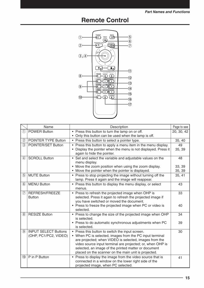
Part Names and Functions
Remote Control
MENU
ZOOM
RESIZE
OHP BRIGHTNESS
PC1/PC2 VOLUME
VIDEO OHP STORED IMAGE
ROTATIONPOSITION
V H
P in P LIVE KEYSTONE
FREEZE
POINTER/SET
POWER
POINTER TYPE REFRESH
MUTE
q t
!1
!2
!7
!3
yuw
i
o
!0
re,
!4
!5
!6
Nameq POWER Button
w POINTER TYPE Buttone POINTER/SET Button
r SCROLL Button
t MUTE Button
y MENU Button
u REFRESH/FREEZEButton
i RESIZE Button
o INPUT SELECT Buttons(OHP, PC1/PC2, VIDEO)
!0 P in P Button
Description• Press this button to turn the lamp on or off.• Only this button can be used when the lamp is off.• Press this button to select a pointer type.• Press this button to apply a menu item in the menu display.• Display the pointer when the menu is not displayed. Press it
again to hide the pointer.• Set and select the variable and adjustable values on the
menu display.• Move the zoom position when using the zoom display.• Move the pointer when the pointer is displayed.• Press to stop projecting the image without turning off the
lamp. Press it again and the image will reappear.• Press this button to display the menu display, or select
menus.• Press to refresh the projected image when OHP is
selected. Press it again to refresh the projected image ifyou have switched or moved the document.
• Press to freeze the projected image when PC or video isselected.
• Press to change the size of the projected image when OHPis selected.
• Press to do automatic synchronous adjustments when PCis selected.
• Press this button to switch the input screen.• When PC is selected, images from the PC input terminal
are projected; when VIDEO is selected, images from thevideo source input terminal are projected; or, when OHP isselected, an image of the printed matter or documentplaced on the scanner on the main unit is projected.
• Press to display the image from the video source that isconnected in a window on the lower right side of theprojected image, when PC selected.
Page to see20, 30, 42
35, 4049
35, 39
48
33, 3935, 3935, 41
43
33
40
34
39
30
41
Cha.02 04.7.29, 11:44 AM15

16
!1 ZOOM Buttons
!2 POSITION Buttons
!3 BRIGHTNESS Buttons
!4 VOLUME Buttons
!5 OHP STORED IMAGEButtons
!6 KEYSTONE Button!7 LIVE Button
• These buttons adjust the zoom ratio. Pressing the button reduces the image, and pressing the buttonenlarges the image.
• Press to change the orientation of the projected imagewhen OHP is selected. Press the
ROTATION
button to reverse thetop and bottom of the projected image. Press the
V H
button to switch between vertical display and horizontaldisplay.
• These buttons adjust the brightness. Pressing the button darkens the projected image, and pressing the button lightens the projected image.
• Adjust the volume when PC or video is selected. Press the button to reduce the volume. Press the button to
increase the volume.• A maximum of eight pages of images are stored to internal
memory when the display is refreshed, when OHP isselected. Press to access those images.
• Press this button to compensate keystone.• Press to confirm the projected image while moving the
document when OHP is selected.
33, 39
32
32, 38
40
34
2133
Cha.02 04.7.29, 11:44 AM16

17
Part Names and Functions
Remote Control Operations
• Use the remote control within about seven meters (7.7 yards) from the remote controlsensors (on the front and rear sides) of the projector and within 10 degrees to the left andright. This distance may become shorter as the battery wears down.
• The remote control does not work if there are obstacles between the remote control and theremote sensor on the main unit.
3. Return the battery compartment coverto its original position.
2. Install two batteries in the batterycompartment, making sure that they arealigned as indicated by the (+) and (-)marks.
CAUTION
Handling the remote control• Do not subject the remote control to such severe impact as dropping it on the floor. Doing so may damage it and
cause it to cease functioning.• Keep the remote sensor away from water. Wipe the remote control immediately if it gets wet.• Avoid heat or hot water. Remove the dry cells when you are not using the remote control for a long period of time.• Do not mix new and old dry cells, or use different types of dry cells at the same time.• Do not disassemble or heat batteries, or throw them into a fire.• Follow your local government's disposal instructions for used dry cells.• The remote control may not work when it is used near inverter-driven equipment.• The remote control may not work or may work ineffectively when it is used near inverter-driven fluorescent
lighting.
NOTE
• When replacing the batteries, buy AAA batteries.• Ni-Cad batteries or other chargeable batteries cannot be used. Use manganese batteries or alkaline batteries.
Battery Replacement1. Remove the battery compartment cover
by pushing in the claw and lifting thecover up.
Cha.02 04.7.29, 11:44 AM17

18
How to Install the Projector
Installation Sequence
Adjusting the TiltThe position and tilt angle of the projected image can be adjusted by adjusting the adjustablefeet. Press both the left and right tilt adjustment levers to lift the main unit, and release themwhen the desired height is reached. You can fine-adjust the tilt by turning the bottom sectionof the adjustable feet. Turning this section counterclockwise raises the main unit, and turningit clockwise lowers the main unit. Also, you can adjust the tilt angle by turning the adjustablefoot located on the rear left of the main unit.
CAUTION
• Do not tilt the main unit at extreme angles by turning only one side of the adjustable feet. Doing so may cause themain unit to slip or fall down, resulting in accidents or failures.
• Vent A on the bottom of the main unit takes in air to cool the inside of the projector. As air is taken in by largesuction force, cloth or paper may be sucked in against the vent. If this happens, the temperature inside may buildup, and cause an accident or failure.
• The rubber feet may soil the installation surface depending on where the projector is installed.
Check the installation site and image size.
Prepare the screen. Install the projector. Install the input devices. End
See “Projection Distance and Projected Image Size” on page 19.
PC, video source, etc.
Extendsfoot.
Retractsfoot.
Retractsfoot.
Extendsfoot.
Adjustable feet
Tilt adjust levers
Cha.03 04.7.29, 11:45 AM18

19
How to Install the Projector
Projection Distance and Projected Image SizeUse the following diagrams to determine the projected image size and the type of screenrequired for any given projector location.
• The projection distance that provides good focusing is 1.4 m (1.5 yd) to 13 m (14 yd) fromthe front of the lens. Install the projector within this range.
CAUTION
Installation location• Do not install the projector in excessively hot or cold locations. The ambient temperature should be within 0°C to
35°C (32°F to 95°F).• Position the projector so that the screen does not directly receive sunlight or other light from other lighting.
Otherwise, the projected image becomes white and is difficult to view. In a bright room, use a curtain or othermeans to darken the area around the screen.
• Do not install the projector where it will be subject to excessive humidity, dust, or cigarette smoke.Otherwise, image quality may deteriorate as dirt builds up on the lens, mirrors and other optical components.
• Do not install the projector in a small room with poor air circulation or any place where the air vents may beblocked. Temperature build-up inside the projector may result in fire or a failure. (Vents are located on the bottomand right side of the projector.)
HorizontalDimension
Ver
tical
Dim
ensi
on
Projected Image Size
508 x 381
610 x 457
406 x 305
305 x 229
203 x 152
102 x 76(cm)
250
300
200
150
100
50(inch)
Width x Height 1 3 5 7 9 11 13 15 (m)
Pro
ject
ed Im
age
Siz
e
Projection Distance
Projection Distance(1.43 m to 14.86 m/1.5 yd to 16.2 yd)
Wide
Tele
Wide: The largestimage that can beprojected byadjusting theimage with thezoom lens.
Tele: The smallestimage that can beprojected byadjusting theimage with thezoom lens.
Cha.03 04.7.29, 11:45 AM19

20
Typical Installation
1. Select the installation sitePlace the projector on an even and stable surface such as a table.
2. Connect the power cord (supplied), and press the POWER
button (or POWER
button.)
3. Turn the direction of the lens so that it is perpendicular to the screen.Turn the unit to the left or right so that the top and bottom lines of the projected imageare parallel.
4. Adjust the adjustable feet to move the projected image to the desiredheight. (Adjust the tilt angle between 0° to 7°.)
The position of the projected image can be moved up or down by adjusting tilt.
90°
Adjustable feet
Cha.03 04.7.29, 11:45 AM20

21
How to Install the Projector
Compensating KeystoneIf the projected image is distorted, you can eliminate the distortion by doing keystonecompensation.
How to Compensate Keystone
Press the KEYSTONE
button (or the KEYSTONE button on theremote control) to display the “Keystone menu.”
Press the u button to make the top ofthe projected image narrower.
Press the
u
button to make thebottom of the projected imagenarrower.
Press the v button to make the leftside of the projected image narrower.
Press the u button to make the rightside of the projected image narrower.
Press the MENU
button (or the MENU
button on the remote control) to return to “0” (Nocompensation).
NOTE
• When keystone compensation is performed, the resolution at the edges of the projected image is reduced, makingsmall characters difficult to read. To prevent this, place the projector on as level a surface as possible, and set theKeystone menu to “0” (No compensation).
• As image processing is performed for keystone compensation, displayed images (characters, etc.) are displayedslightly blurred when keystone compensation is used compared with when it is not used.
• When displaying an image with VGA resolution less than 640 x 480 pixels with a excessive horizontal keystonecompensation may cause parts of the image to become fuzzy. See page 26 for more information.
• The degree to which keystone compensation can be adjusted depends on the image signal.• If the horizontal value is adjusted to its largest (or smallest) the vertical adjustment value can not be moved in the plus
direction when doing keystone compensation.
Keystone
Hor izontal
Ver t ical
0
0
MENU
SET
Set standard
Quit
Keystone menu
Cha.03 04.7.29, 11:45 AM21

22
Connecting to a Personal Computer
CAUTION
Cautions on Connection• Before connecting other devices, turn off each device to protect the projector and other connected devices.• For details of how to connect and use devices connected to the projector, refer to the User’s Manual for each
device.• Sometimes images are not displayed on the screen properly when they are displayed on a notebook PC LCD as
well. If this happens, turn the notebook PC display off to remedy this. The method for turning off a notebook PCdisplay varies according to the notebook PC manufacturer. For details, refer to the User’s Manual of the notebookPC.
• You may not be able to connect the projector depending on the model of personal computer and personalcomputer settings. Consult your dealer for details.
Connecting to a Personal Computer List of cables and adapters
PC/AT compatible
machine
Apple Macintosh
Notebook,
desktop
Notebook
Desktop
15-pin Mini D-Sub (VGA)
Respective companies
Power Book G3 (with Mini D-Sub 15-pinmonitor output terminal)
Power Book (excluding iBook, DUO,100, 140, 145B, 150, 170, etc.)
PowerBook DUO
* Models having no monitor outputterminal such as iBook, Power Book100, 140, 145B, 150, 170 cannot beconnected.
G3, G4 (with Mini D-Sub 15-pin monitoroutput terminal)
Various models (excluding integratedmonitor type)
* Monitor integrated models such asiMac, Classic and some Performamodels cannot be connected as theyhave no monitor output terminal.
Supplied cable
Supplied cable
Adapter (third party)*+ adapter +supplied cable
Adapter (third party)*+ adapter +supplied cable
* DUO Dock or Mini Dock isrequired.
Supplied cable
Adapter + supplied cable
* The separate display adapter(Apple) is required for thePower Mac 6100.
Manufacturer TypeRGB output
ConnectionModel
* Adapter (sold separately): Power Book exclusive adapter (Apple Power Book Video Adapter Cable M3927LL/A, or equivalent). It may beprovided with the Power Book.
Cha.04 04.7.29, 11:45 AM22

23
Connecting to a Personal Computer
About the PC Input and Output
Terminals15-pin mini D-Sub connectors are used for the PC input and output terminals. Thefollowing shows the relationship between the pins and the input and output signals.
q RED VIDEO y GND !1 NCw GREEN VIDEO u GND !2 Pull up (+5V)e BLUE VIDEO i GND !3 H.SYNCr GND o NC !4 V.SYNCt NC !0 GND !5 Pull up (+5V)
NOTE
• This projector uses a 15-pin RGB input and an analog type output terminals. For this reason, it cannot beconnected to a digital output type personal computer.
• Plug and play is not supported.
5 4 3 2 1
10 9 8 7 6
15 14 13 12 11
Cha.04 04.7.29, 11:45 AM23

24
About RGB Video Output
Signal timingThe following shows the timing that signals are output from the RGB video output terminal.(XGA 60Hz speed or equivalent)The video signal output is determined by whether “PC/OHP” or “OHP” is selected in “RGB-OUT Selection” on the “Setting 2” menu. See page 46 for more information.
Verticalsync signal
Horizontalsync signal
r i
e u
w y
q t
Horizontalsync signal
Vertical sync signal
Scan mode Non-interlaced
q Cycle 20.677 µsw Sync signal width 2.092 µse Back porch 2.462 µsr Display interval 15.754 µs t Cycle 806 Hy Sync signal width 6 Hu Back porch 29 Hi Display interval 768 H
NOTE
• The screen is sometimes not displayed normally depending on the monitor or projector that is connected.• Images from a PC are output in standby.
Cha.04 04.7.29, 11:45 AM24

25
Connecting to a Personal Computer
Images are not projected correctly even though they are displayed normallyon the notebook PC screen
1 Verify the functions of the notebook PC.Even if the LCD screen of a notebook PC displays normal images, the projected imagesmay be displayed incorrectly. In most cases, because of the limitations of the notebookPC, the simultaneous display function (the external output signals are sent outsimultaneously while the images are displayed on the PC screen) produces signals, whichdo not satisfy the standard specification and are outside the range supported by theprojector. In this case, the incorrect display images can not be corrected even if the fineadjustments are made at the projector side. The correct images may be projected if onlyexternal output signals are provided without using the simultaneous display. Refer to theuser’s manual of your notebook PC for details.
When Images on the Personal Computer Screen are not Projected
Check the following when images on the personal computer screen are not projected orprojected images are incorrect.
When images are not projectedWhen external output signals are input to the MP-700 from the PC, “No PC signal” isdisplayed on the screen. When this is displayed, check the following.
1 Try restarting the personal computer.The MP-700 is sometimes not recognized by the PC if it is connected after the PC isstarted up. If this happens, images are not projected as external output signals are notoutput from the PC.
2 Check the functions on the personal computer.Some notebook PCs require a special operation to transmit the signals from the externaloutput terminal. The external output signals may not be transmitted from the notebook PCunless the operation is performed. Refer to the manuals of your notebook PC for theinformation about how to output signals from the external output terminal.
Procedure example• In the case of IBM PC/AT
Press Fn key together with one of the keys, F1 - F12 . Thisprocedure may vary depending on the model.)
* The above table summarizes conditions that have occurred to date; it is not a comprehensivesummary of all connections.
* Company names and product names listed in the above table are trademarks or registeredtrademarks of respective companies.
List of remedies when connection trouble with the PC occurs
Manufacturer Series External Output Switching Method
IBM Think Pad Fn+f7
COMPAQ CONTURAARMADA
LATITUDEDELL
Fn+f4
Fn+f8
Cha.04 04.7.29, 11:45 AM25
26
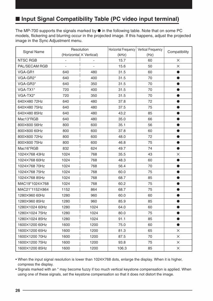
Signal NameResolution Horizontal Frequency Vertical Frequency
Compatibility(Horizontal Vertical) (kHz) (Hz)
NTSC RGB - - 15.7 60
PAL/SECAM RGB - - 15.6 50
VGA-GR1 640 480 31.5 60
VGA-GR2* 640 400 31.5 70
VGA-GR3* 640 350 31.5 70
VGA-TX1* 720 400 31.5 70
VGA-TX2* 720 350 31.5 70
640480 72Hz 640 480 37.8 72
640480 75Hz 640 480 37.5 75
640480 85Hz 640 480 43.2 85
Mac13"RGB 640 480 35.0 66
800600 56Hz 800 600 35.1 56
800600 60Hz 800 600 37.8 60
800600 72Hz 800 600 48.0 72
800600 75Hz 800 600 46.8 75
Mac16"RGB 832 624 49.7 74
1024768 43Hz 1024 768 35.5 43
1024768 60Hz 1024 768 48.3 60
1024768 70Hz 1024 768 56.4 70
1024768 75Hz 1024 768 60.0 75
1024768 85Hz 1024 768 68.7 85
MAC19"1024768 1024 768 60.2 75
MAC21"1152864 1152 864 68.7 75
1280960 60Hz 1280 960 60.0 60
1280960 85Hz 1280 960 85.9 85
12801024 60Hz 1280 1024 64.0 60
12801024 75Hz 1280 1024 80.0 75
12801024 85Hz 1280 1024 91.1 85
16001200 60Hz 1600 1200 75.0 60
16001200 65Hz 1600 1200 81.3 65
16001200 70Hz 1600 1200 87.5 70
16001200 75Hz 1600 1200 93.8 75
16001200 85Hz 1600 1200 106.3 85
Input Signal Compatibility Table (PC video input terminal)
The MP-700 supports the signals marked by in the following table. Note that on some PCmodels, flickering and blurring occur in the projected image. If this happens, adjust the projectedimage in the Sync Adjustment menu.
• When the input signal resolution is lower than 1024768 dots, enlarge the display. When it is higher,compress the display.
• Signals marked with an * may become fuzzy if too much vertical keystone compensation is applied. Whenusing one of these signals, set the keystone compensation so that it does not distort the image.
Cha.04 04.7.29, 11:45 AM26

27
Connecting to a Personal Computer
Basic connections
NOTE
The personal computer has input terminals for both image and sound for “1” and “2”. Hook up the sound and imageto the corresponding terminals. If they are not hooked up to the corresponding terminals, the image and sound willnot be output correctly.
Connecting to IBM NOTE and Compatible
NOTE
After you have connected the cable, check the external CRT output/internal LCD output states and set the mode inthe software running on the PC.The connection with the PC will not be made if you do not set the external CRT output mode.
To audio outputterminal on PC
To RGB input connector on monitor
To analog RGBconnector on PC
The connector cable model No. differs according to the type of PC.
Terminal panel on the back of the MP-700 main unit
To speakerinput terminals
Fix the connector cable using the screw-in fasteners.
Signal cable (supplied)
To RGB-IN1 or RGB-IN2 terminal
MP-700
Cha.04 04.7.29, 11:45 AM27

28
Connecting to an IBM Desktop and Compatible (DOS/V)
NOTE
When connecting the projector directly to the PC without using the monitor supplied with the PC, you can connectby the cable only.
Connecting to Apple Macintosh NotebookExcluding Power Book Duo, 100, 140, 145B, 150, 170
NOTE
• When connecting the Power Book Duo, the Duo Dock or Mini Dock is required.• The Power Book display adapter is sometimes not supplied with the Power Book. If it is not supplied, buy a
separate display adapter from a Macintosh computer store. (Apple M3927LL/A or equivalent)
Cable supplied with monitor
Signal Cable(supplied)
To RGB-OUT terminal
To RGB-IN1 or RGB-IN2 terminal
MP-700
Signal cable(supplied)
Display adapterfor Power Book
Conversion adapter(not supplied)
To RGB-IN1 or RGB-IN2 terminal
MP-700
Cha.04 04.7.29, 11:45 AM28

29
Connecting to a Personal Computer
Connecting to a Video Source or DVD Player
Images from a video source or DVD player can be projected on a large screen.
NOTE
• When both VIDEO and S-VIDEO are connected, S-VIDEO is given higher display priority.• Before using the video source or DVD player, close the materials cover. (Otherwise, the glass on the scanner may
vibrate and cause a rattling sound.)
DVD Player Video Source
To Video Output Terminal
Or
To Audio Output Terminal
Terminal panel on the back of the MP-700 main unit
Cha.04 04.7.29, 11:45 AM29

30
Basic Operation
Preparation
1 Connect the power cord.
The projector is in the standby mode, and the power indicatorLED lights (red).
Press the POWER button. The fan spins, the LED lights, andthe ON/STANDBY LED lights (green).The LAMP/COVER LED lights (green).If the LAMP/COVER LED lights red after turning on thePOWER button, then there is something wrong. (See page 62for details.)
NOTE
Make sure that the lens cap has been removed before turning on the power.
2 Select the external input device.Select the video source to be displayed from OHP, PC1/PC2,or VIDEO.
NOTE
When PC/VIDEO is selected and the device is not connected, or the connected device is not turned on, “Noinput” is displayed.
Remote Control Operation
Main Unit Operation
VIDEOPC1/PC2OHP
ON/STANDBY
LAMP/COVER
TEMP
1
2
The selected input display is displayed.
OHP PC/video
See page 38.See page 31.
OHP
PC1/PC2
VIDEO
Cha.05-1 04.7.29, 11:47 AM30

31
Basic Operation
Basic Operations in the OHP Mode
NOTE
The projected image in the OHP display (projection of actual object) may be slightly distorted as a very wide-angle lens is used.
1 Adjust the size of the projected image.Rotate the zoom adjuster on the projection lens to adjust thesize of the projected image.
2 Adjust the focus.Adjust the focus adjuster on the projection lens until theprojected image is sharp.
3 Compensate the keystone.See “Compensating Keystone” on page 21.
4 Check the OHP’s initial screen.When you select OHP, the “Set your document and press the refresh button” message appears andthe projected image becomes all white, and a window that shows how the document is movingappears on the bottom right of the projected image.
Main Unit Operation
Remote Control Operation
2
5
3,6,7,8,9,10,11,12,13,14,15,16,18
1
KEYSTONE
KEYSTONE
Cha.05-1 04.7.29, 11:47 AM31

32
5 Set the object you want to project.Open the materials cover, and place the document or printedmatter you want to project on the scanner.A video image of the projected material appears in thewindow.
Close the materials cover.
NOTE
Objects can be projected even if the materials cover is not closed. However, unwanted objects willalso be picked up, making the projected image difficult to view.
6 Adjust the brightness.Pressing the button (or the button on the remotecontrol) darkens the projected image, and pressing the button (or the button on the remote control) lightens theprojected image.
NOTE
When projecting dark documents or printed matter, adjust to lighten the projected image, and when projectingbright documents or printed matter, adjust to darken the projected image.
7 Switch the orientation of the projected image.Orient the image in the direction of the document.Press the POSITION button to switch the orientation of theprojected image.ROTATION button: Flip the projected image top to bottom.V ↔ H button: Switch the image from a vertical to a
horizontal display.
Main Unit Operation
Remote Control Operation
BRIGHTNESS
BRIGHTNESS
Main Unit Operation
Remote Control Operation
V HROTATION
POSITION
ROTATIONPOSITION
V H
Cha.05-1 04.7.29, 11:47 AM32

33
Basic Operation
8 Freeze the projected image.Press the REFRESH/FREEZE button to project a frozenimage, of the material that you set in step five, on the whitearea of the projected image.
9 Close the window.Press the LIVE button to close the window that is displayed,the entire projected image freezes.
10 Adjust the zoom ratio.You can adjust the zoom between 1x to 6.25x.Pressing the button (or the button on the remotecontrol) reduces the image, and pressing the button (orthe button on the remote control) enlarges the image.
11 Move the zooming position.Press the arrow buttons on the remote control to move thezooming position of the image. You can move in eightdirections. (Up, down, left, right and diagonally).
Main Unit Operation
Remote Control Operation
LIVE
LIVE
Main Unit Operation
Remote Control Operation
ZOOM
ZOOM
Remote Control Operation
REFRESH
FREEZE
FREEZE
REFRESH
Main Unit Operation
Remote Control Operation
SCROLL
POINTER/SET
Main Unit Operation
Cha.05-1 04.7.29, 11:47 AM33

34
12 Project a full-screen image.When projecting a vertical image, if white space is projectedon the left and right of the image, press the RESIZE button toproject the image in full-screen. (Adjusting the zoom returnsthe image to normal.)
13 Make the projected image live.There are the two following methods to move the documentwhile checking the projected image.q Make the window live.
Set “Window” in “Movie mode” in the quick menu (page52). Pressing the LIVE button displays live images in thewindow on the bottom right of the image.
w Make the entire image live.Set “Full” in “Movie mode” in the quick menu (page 52).Pressing the LIVE button displays live images on the entireprojected image at about 1 frame per second. In this setting,the image doesn't change even if you press the LIVE button.
14 View OHP history.When you press the REFRESH button and the imagefreezes, a maximum of eight pages of the OHP images arestored on the internal MP-700 memory.Press the OHP STORED IMAGE button to view and changethe stored images on the internal memory. See page 37 fordetails.
button: Display the image previous to the currentlydisplayed image from stored image.
button: Display the image following the currentlydisplayed image from stored image.
You can switch the stored images from the quick menu (page52) when viewing the OHP image history.
NOTE
• Pressing the POWER button and going into standby erases the OHP stored images.• The brightness can not be adjusted when viewing OHP stored image. Adjust the brightness before
pressing the REFRESH/FREEZE button.
15 Save the image on the CF card.See “Saving OHP” on page 55.
Main Unit Operation
Remote Control Operation
LIVE
LIVE
Main Unit Operation
Remote Control Operation
OHP STORED IMAGE
VOLUME
OHP STORED IMAGE
Main Unit Operation
Remote Control Operation
RESIZE
RESIZE
Main Unit Operation
OHP SAVE
Cha.05-1 04.7.29, 11:47 AM34

35
Basic Operation
16 Display the pointer.Press the SET/POINTER button to display the pointer. Pressit again to hide the pointer.
Press the SCROLL button to move the pointer.
NOTE
Adjusting the zoom or the brightness while the pointer is displayed may cause it to disappear momentarily, but itwill reappear after a short time.
17 Select the type of pointer.You can switch the type of pointer with the POINTER TYPEbutton on the remote control. (Select from , , or .)You can also select the type from “Pointer type” on the“Setting 2” menu. See page 46 for details.
18 Mute the image.Press the MUTE button to stop projecting the image withoutturning off the lamp. You can select the image projected whilethe image is muted from the following two images.q Project a completely black image while the projected
image is muted.Set “Black” in “Mute mode” on the “Setting 2” menu (page46). While the image is muted, the projecting black image
icon is displayed on the top right side of the projectedimage.
w Project an arbitrary image while the projected image is muted.Set “Wallpaper” in “Mute mode” on the “Setting 2” menu(page 46).While the image is muted, the projecting wallpaper image
icon is displayed on the top right side of the screen.See page 60 for information on how to set wallpaper as animage.
NOTE
After the projected image has been muted for a certain amount of time (about 15 minutes) it automatically goesinto standby.
Main Unit Operation
Remote Control Operation
MUTE
MUTE
Main Unit Operation
Remote Control Operation
SET
POINTER
POINTER/SET
Remote Control OperationPOINTER TYPE
Cha.05-1 04.7.29, 11:47 AM35

36
Document Orientation and Scan SizePlace the document or printed matter face down at the orientation shown in the figure below.
The maximum size that documents or printed matter can be scanned is 216 mm/8.5 in(vertical) and 288 mm/11.3 in (horizontal). For this reason, the projected sizes are as followswhen an A4-size sheet of paper is placed at the respective orientations. (Shaded section is theprojected area.)
ABCabc
Parts protruding outside the scan area arenot projected on the screen. To project theseparts, move the paper.
Displaying video in the windowWhile it is possible to display video images in the window, the video image is low resolutionand is displayed against a background of a high definition frozen image on the main part of theprojected image.
297 mm/11.6 in (paper size)
288 mm/11.3 in (scan size)
210
mm
/8.3
in (
pape
r si
ze)
216
mm
/8.5
in (
scan
siz
e)
A4 horizontal orientation
High definitionfrozen image.
Low-resolution video
When the window is displayed, the“BRIGHTNESS,” “V ↔ H,” and “ROTATION”buttons are enabled for the window, but theZOOM buttons are enabled for the main partof the projected image. (When you press theZOOM buttons, the window disappearsmomentarily, but is displayed again after ashort time.
Cha.05-1 04.7.29, 2:11 PM36

37
Basic Operation
Displaying OHP stored imagePressing the buttons display and switch the stored images in the internal memory.
button: Displays the image previous to the stored image that is currently displayed. button: Displays the image following the stored image that is currently displayed.
* Pressing the button while a stored image is not displayed causes the most recentlyrefreshed image that was stored to be displayed.
When you press the REFRESH button and the image freezes, a maximum of eight pages ofthe OHP images are stored on the internal MP-700 memory.Press the POWER button, then after selecting OHP mode, the image of the first frozen imageis stored to position q in the diagram below. After that, every time you refresh the display theimages are stored in the internal memory. When the stored images exceed the maximum ofeight images the oldest images are overwritten in the order shown in the diagram below(starting from q).
q w e r
i u y t
Cha.05-1 04.7.29, 11:47 AM37

38
Basic Operation of PC or Video Input
1 Adjust the size of the projected image.Rotate the zoom adjuster on the projection lens to adjust thesize of the projected image.
2 Adjust the focus.Adjust the focus adjuster on the projection lens until theprojected image is sharp.
3 Compensate keystone.See “Compensating Keystone” on page 21.
4 Adjust the brightness.Pressing the button (or the button on the remotecontrol) darkens the projected image, and pressing the button (or the button on the remote control) lightens theprojected image.
Main Unit Operation
Remote Control Operation
2
3,4,5,6,7,8,10,11,13 1
KEYSTONE
KEYSTONE
Main Unit Operation
Remote Control Operation
BRIGHTNESS
BRIGHTNESS
Cha.05-1 04.7.29, 11:47 AM38

39
Basic Operation
5 Adjust the zoom ratio.You can adjust the zoom between 1x to 4x.Pressing the button (or the button on the remotecontrol) reduces the image, and pressing the button (orthe button on the remote control) enlarges the image.
6 Move the zooming position.Press the arrow buttons on the remote control to move thezooming position of the image. You can move in eightdirections. (Up, down, left, right and diagonally).
7 Synchronized AdjustmentsPress the RESIZE button to do automatic synchronousadjustments of each setting to the most suitable status on the“Sync Adjust” menu (Page 45).
8 Display the pointer.Press the SET/POINTER button to display the pointer. Pressit again to hide the pointer.
Press the SCROLL button to move the pointer.
NOTE
Adjusting the zoom or the brightness while the pointer is displayed may cause it to disappear momentarily, but itwill reappear after a short time.
Main Unit Operation
Remote Control Operation
ZOOM
ZOOM
Main Unit Operation
Remote Control Operation
SCROLL
POINTER/SET
Main Unit Operation
Remote Control Operation
RESIZE
RESIZE
Main Unit Operation
Remote Control Operation
SET
POINTER
POINTER/SET
Cha.05-1 04.7.29, 11:47 AM39

40
9 Select the type of pointer.You can switch the type of pointer with the POINTER TYPEbutton on the remote control. (Select from , , or .)You can also select the type from “Pointer type” on the“Setting 2” menu.
10 Adjust the volume.Press the button to reduce the volume.Press the button to increase the volume.
11 Freeze the projected image.Press the FREEZE button to freeze the image from thepersonal computer or video.To unfreeze the image, press the FREEZE button again, orpress the LIVE button.
NOTE
• You can not adjust the brightness when the image is frozen. Adjust the brightness before pressing theFREEZE button.
• Press the INPUT SELECT button to unfreeze the image when it is frozen.
Remote Control OperationPOINTER TYPE
Main Unit Operation
Remote Control Operation
OHP STORED IMAGE
VOLUME
VOLUME
Main Unit Operation
Remote Control Operation
REFRESH
FREEZE
FREEZE
REFRESH
Cha.05-1 04.7.29, 11:47 AM40

41
Basic Operation
12 Display images from the personal computerand the video at the same time.If you select personal computer input while a video source and apersonal computer are both connected, you can display videoimages in the window at the lower right side of the projected image.Set “Picture in Picture” to “ON” on the quick menu to displayvideo images. See page 53 for details.
NOTE
• The P in P button is only enabled when a personal computer is selected. You can not use it when video isselected.
• You can not use the picture in picture function if the signal from the personal computer is not being input.
13 Mute the image.Press the MUTE button to stop projecting the image withoutturning off the lamp. You can select the image projected whilethe image is muted from the following two images.q Project a completely black image while the projected image
is muted.Set “Black” in “Mute mode” on the “Setting 2” menu (page46). While the image is muted, the projecting black image
icon is displayed on the top right side of the projectedimage.
w Project an arbitrary image while the projected image ismuted.Set “Wallpaper” in “Mute mode” on the “Setting 2” menu(page 46).While the image is muted, the projecting wallpaper image
icon is displayed on the top right side of the projectedimage.See page 60 for information on how to set wallpaper as animage.
NOTE
After the projected image has been muted for a certain amount of time (about 15 minutes) it automatically goesinto standby.
Remote Control Operation
P in P
Main Unit Operation
Remote Control Operation
MUTE
MUTE
Cha.05-1 04.7.29, 11:47 AM41

42
How to Quit
1 Turn the lamp off.Press the POWER button. (Hold down for at least onesecond.)
“Press POWER button again to turn off.” is displayed on theprojected image.
Press the POWER button again.The LAMP/COVER LED blinks (green), and goes out afterabout one minute.The ON/STANDBY LED lights (red.)
NOTE
The lamp will not turn on even if you press the POWER button if the LAMP/COVER LED is blinking green.To turn the lamp on again, press the POWER button again after the ON/STANDBY LED lights red.
2 Disconnect the power cord.
The ON/STANDBY LED on the operation panel goes out.
CAUTION
• Do not disconnect the power cord before the lamp goes off or the LAMP/COVER LED lights. Doing so mayshorten the life of the lamp.
• Disconnect the power cord from the power outlet if you are not going to use the projector for a long period of time.• After disconnecting the power cord from the power outlet, wait a certain period of time (about 10 seconds) before
connecting it again.
Remote Control Operation
Main Unit Operation
POWER
2
1
POWER
ON/STANDBY
LAMP/COVER
TEMP
Cha.05-1 04.7.29, 11:47 AM42

43
Basic Operation
Performing Various Adjustments
Menu StructureYou can perform various adjustments and make various settings by operating the buttonswith the menu display displayed on the projected image.There are two menus, the “Quick menu” on which there are frequently used items, and the“Main menu” on which more detailed settings can be done.When a personal computer or video is connected and the power is on, you can open the“Quick menu” by pressing the
MENU
button (or the MENU
button on the remote control.) (See Page52 for information about the Quick menu.)Press the
MENU
button (or the MENU
button on the remote control) again and the Main menuopens. You can go to the Adjust Settings menu from the Main menu display. A map of themenu displays is shown below.
<When PC Input is Selected>
Displayed only when PC input is selected
Main menu Menu
Displayed only when OHP input is selected
Displayed only when PC input is selected
Displayed only when VIDEO input is selected
Displayed only when VIDEO input is selected
MENU
Quit
MENU
Sync adjustment
Image adjustment
Setting 1
Setting 2
Language selection
Projection mode
Return
Video select
PAL B,G,H,I
Auto
PAL M
NTSC 4.43
NTSC 3.58
SEC AM
PAL N
PAL 60
Return
Projection mode
Rear
Front
Return
Language selection
ENGLISH
Standard Return
Setting 1
Auto power off ON / OFF
Start-up display ON / OFF
Economy mode ON / OFF
Lamp usage time
Input signal
24H
1024 x 768 / 48.6KHz 60H
Standard Return
Setting 2
Pointer type
RGB-OUT select PC · OHP / OHP
Mute mode Black / Wallpaper
Standard Return
Sync adjustment
Phase 0
Horizontal 0
Vertical 0
Clock 0
Standard Return
Image adjustment
Red 0
Blue 0
Gamma PHOTO / TEXT
Image mode Standard Natural
Standard Return
Image adjustment
Brightness 0
Red 0
Blue 0
Sharpness 1 2 3 54
Image mode Sharpness sRGB
Contrast 0
Standard Return
Image adjustment
Brightness 0
Color 0
Sharpness 3
Tint 0
Image mode Standard Natural
Contrast 0
(or the button on the remote control)
(or the button on the remote control)
<When VIDEO Input is Selected>
<When OHP is Selected>
Quit
MENU
Setting 1
Setting 2
Image adjustment
Language selection
Projection mode
Video select
Setting 1
Setting 2
Image adjustment
Language selection
Projection mode
Quit
MENU
SET
POINTERSET/POINTER
MENU
Cha.05-2 04.7.29, 11:47 AM43

44
Description of Menu ItemsThe following describes each of the menu displays, and the items and functions that can beset in these menu displays. For details of how to set these menu items, see “BasicOperation” on page 48.
Image Adjustment (when PC input is selected)
<Image Adjustment Menu>
Image Adjustment (when VIDEO input is selected)
<Image Adjustment Menu>
Menu Item
Contrast
Brightness
Color
Sharpness
Tint
Image mode
Setting Item
-100 ~ +100
-100 ~ +100
-100 ~ +100
0 ~ 6
-100 ~ +100
Standard/Natural
Description
Adjusts the contrast of theprojected image.
Adjusts the brightness of theprojected image.
Adjusts the hue of projected images.
Adjusts image sharpness.
Adjusts the tint of projected images.
If you want to display an image thathas high contrast and sharpnessselect “Standard”; if you want toreproduce colors that are close tothe original select “Natural.”
Standard Return
Image adjustment
Brightness 0
Red 0
Blue 0
Sharpness 1 2 3 54
Image mode Standard sRGB
Contrast 0
Standard Return
Image adjustment
Brightness 0
Color 0
Sharpness 3
Tint 0
Image mode Standard Natural
Contrast 0
Menu Item
Contrast
Brightness
Red
Blue
Sharpness*
Image mode
* Sharpness is especially effective when the images areenlarged and zoomed or if keystone compensation has beendone.
Setting Item
-100 ~ +100
-100 ~ +100
-100 ~ +100
-100 ~ +100
1 ~ 5
Standard/sRGB
Description
Adjusts the contrast of theprojected image.
Adjusts the brightness of theprojected image.
Adjusts the depth of the color red.
Adjusts the depth of the color blue.
Adjusts image sharpness. Thehigher the number goes the moreclear the image becomes. Thestandard is “3.”
If you want to display an imagethat has high contrast andsharpness select “Standard”; ifyou want to reproduce colors thatare close to the original select“sRGB.”
Cha.05-2 04.7.29, 11:47 AM44

45
Basic Operation
Image Adjustment (when OHP is selected)
<Image Adjustment Menu>
Sync Adjustment (only when PC input is selected)
<Sync Adjustment Menu>
NOTE
Menu items sometimes cannot be adjusted within the range -100 to +100 depending on the PC input signal.
Menu Item
Red
Blue
Image mode
Gamma
Setting Item
-100 ~ +100
-100 ~ +100
Standard/Natural
PHOTO/TEXT
Description
Adjusts the depth of the color red.
Adjusts the depth of the color blue.
If you want to display an image thathas high contrast and sharpnessselect “Standard”; if you want toreproduce colors that are close tothe original select “Natural.”
The TEXT setting compensates fortext documents, and the PHOTOsetting compensates for photodocuments.
Select the setting to suit thedocument you are projecting.
Menu Item
Clock
Phase
Horizontal
Vertical
Setting Item
-100 ~ +100
-100 ~ +100
-100 ~ +100
-100 ~ +100
Description
Adjusts the horizontal size of theimage.
Adjusts noise and flickering.
Adjusts the horizontal position ofthe image.
Adjusts the vertical position of theimage.
Standard Return
Image adjustment
Red 0
Blue 0
Gamma PHOTO / TEXT
Image mode Standard Natural
Standard Return
Sync adjustment
Phase 0
Horizontal 0
Vertical 0
Clock 0
Cha.05-2 04.7.29, 11:47 AM45

46
Setting 1
<Setting 1 Menu>
NOTE
In the “Setting 1” menu, the currently set input signals and lamp usage time can be displayed for confirmation.
Setting 2
<Setting 2 Menu>
Menu Item
Auto power off
Start-up display
Economy mode
Setting Item
ON/OFF
ON/OFF
ON/OFF
Description
Sets the auto power off function ON/OFF. When auto power off is set toON, the projector automaticallygoes to standby mode if no signalsare input for a fixed period of time(about 15 minutes).
Sets whether or not to display thelogo while the lamp is on.
Sets the lamp in Economy mode.
Menu Item
Pointer type
RGB-OUTselect
Mute mode
Description
Selects a type of pointer fromamong the three types.
When PC·OHP is selected:If the input selection is OHP, thenthe image is output as an OHPimage for which the timing ischanged to (XGA 60Hz) on page 24.If the input selection is personalcomputer/video, then the personalcomputer image is a straightthrough output.When OHP is selected:No matter what input selection ismade, OHP images are output at(XGA 60Hz) timing on page 24.
Sets the image to be displayedwhen the projected image is muted.When black is selected:The entire projected image appearsblack.When wallpaper is selected:An image stored image as wallpaperis displayed. (See page 60 forinformation on how to setwallpaper.)
Setting Item/ /
PC·OHP/OHP
Black/Wallpaper
Standard Return
Setting 1
Auto power off ON / OFF
Start-up display ON / OFF
Economy mode ON / OFF
Lamp usage time
Input signal
24H
1024 x 768 / 48.6KHz 60H
Standard Return
Setting 2
Pointer type
RGB-OUT select PC · OHP / OHP
Mute mode Black / Wallpaper
Cha.05-2 04.7.29, 11:47 AM46
47
Basic Operation
Return
Language selection
ENGLISH
Return
Projection mode
Rear
Front
Return
Video select
PAL B,G,H,I
Auto
PAL M
NTSC 4.43
NTSC 3.58
SEC AM
PAL N
PAL 60
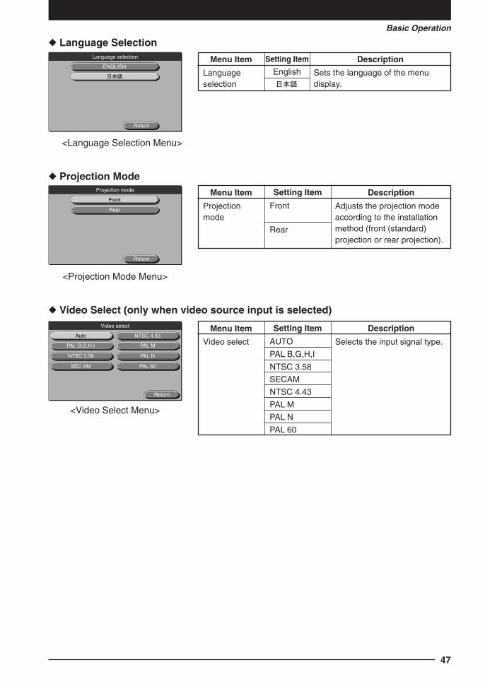
Language Selection
<Language Selection Menu>
Projection Mode
<Projection Mode Menu>
Video Select (only when video source input is selected)
<Video Select Menu>
Menu Item
Languageselection
Setting Item
English
Description
Sets the language of the menudisplay.
Menu Item
Projectionmode
Setting Item
Front
Rear
Description
Adjusts the projection modeaccording to the installationmethod (front (standard)projection or rear projection).
Menu Item
Video select
Setting Item
AUTO
PAL B,G,H,I
NTSC 3.58
SECAM
NTSC 4.43
PAL M
PAL N
PAL 60
Description
Selects the input signal type.
Cha.05-2 04.7.29, 11:47 AM47

48
Main Unit Operation
Remote Control Operation
MENU
ZOOM
RESIZE
OHP BRIGHTNESS
PC1/PC2 VOLUME
VIDEO OHP STORED IMAGE
ROTATIONPOSITION
V H
P in P LIVE KEYSTONE
FREEZE
POINTER/SET
POWER
POINTER TYPE REFRESH
MUTE
2
1
OHP STORE
MENU SET
SCROLL
POINTER
21
Basic Operation
The following describes basic operations in the following menus: “Image Adjustment”, “SyncAdjustment”, “Setting”, “Language Selection”, “Video Adjustment”, and “Projection Mode”.
1 Press the MENU
button (or the MENU
button on theremote control).The main menu is displayed.
<Example: When PC input is selected>
2 Press the buttons to select the itemyou want to set.
<Example: When “Sync adjustment” is selected>
Quit
MENU
Sync adjustment
Image adjustment
Setting 1
Setting 2
Language selection
Projection mode
Quit
MENU
Sync adjustment
Image adjustment
Setting 1
Setting 2
Language selection
Projection mode
Cha.05-2 04.7.29, 11:47 AM48

49
Basic Operation
Main Unit Operation
Remote Control Operation
MENU
ZOOM
RESIZE
OHP BRIGHTNESS
PC1/PC2 VOLUME
VIDEO OHP STORED IMAGE
ROTATIONPOSITION
V H
P in P LIVE KEYSTONE
FREEZE
POINTER/SET
POWER
POINTER TYPE REFRESH
MUTE
4-1
OHP STORE
MENU SET
SCROLL
POINTER
4-1 3
3
When selecting “ON” or “OFF”.
Menu items that require selection of “ON” or “OFF” are“Auto power off”, “Start up display”, and “Economy mode”.For details of these menu items, see page 46.
3 Press the SET
POINTER
button (or the POINTER/SET button on the
remote control).The menu display for the item you want to set is displayed.
To return to the initial settings when you bought theprojector, select “Standard” and press the
SET
POINTER
button (or POINTER/SET
button) in the “Image adjustment”, “Sync adjustment”,
“Setting” or “Video adjustment” menus.
<Example: Sync Adjustment Menu>
4-1 Press the buttons to select the itemyou want to set.
<Example: When “Auto power off” is selected>
Standard Return
Sync adjustment
Phase 0
Horizontal 0
Vertical 0
Clock 0
Standard Return
Setting 1
Auto power off ON / OFF
Start-up display ON / OFF
Economy mode ON / OFF
Lamp usage time
Input signal
24H
1024 x 768 / 48.6KHz 60H
Cha.05-2 04.7.29, 11:47 AM49

50
Main Unit Operation
Remote Control Operation
MENU
ZOOM
RESIZE
OHP BRIGHTNESS
PC1/PC2 VOLUME
VIDEO OHP STORED IMAGE
ROTATIONPOSITION
V H
P in P LIVE KEYSTONE
FREEZE
POINTER/SET
POWER
POINTER TYPE REFRESH
MUTE
4-1
OHP STORE
MENU SET
SCROLL
POINTER
4-1 4-2
4-2
4-2 Press the buttons to select “ON” or“OFF”.
Standard Return
Setting 1
Auto power off ON / OFF
Start-up display ON / OFF
Economy mode ON / OFF
Lamp usage time
Input signal
24H
1024 x 768 / 48.6KHz 60H
When adjusting in single point units
Menu items that require adjustment in single point units are“Contrast”, “Red”, “Blue”, “Clock”, “Phase”, “Horizontal”,“Vertical”, “Tint”, “Color”, and “Sharpness”. For details ofthese menu items, see page 44.
4-1 Press the buttons to select the itemyou want to set.
<Example: When “CLOCK” is selected>
Standard Return
Sync adjustment
Phase 0
Horizontal 0
Vertical 0
Clock 0
Cha.05-2 04.7.29, 11:47 AM50

51
Basic Operation
Main Unit Operation
Remote Control Operation
MENU
ZOOM
RESIZE
OHP BRIGHTNESS
PC1/PC2 VOLUME
VIDEO OHP STORED IMAGE
ROTATIONPOSITION
V H
P in P LIVE KEYSTONE
FREEZE
POINTER/SET
POWER
POINTER TYPE REFRESH
MUTE
4-1, 5
OHP STORE
MENU SET
SCROLL
POINTER
4-2
4-2
4-1, 5 5
5
Standard Return
Sync adjustment
Phase 0
Horizontal 0
Vertical 0
Clock 0
Return
Language selection
ENGLISH
4-2 Press the buttons to adjust the setting.
Others
Other menu items include “Language selection”, “Projectionmode” and “Video select”. For details of menu items, seepage 47.
4-1 Press the buttons to select the itemyou want to set.
<Example: When “Japanese” is selected from the“Language Selection” menu>
5 Press the buttons to select “Quit” andthen press the
SET
POINTER
button (or POINTER/SET button on the
remote control).This returns the display to the main menu. The displayautomatically disappears, and adjustment values arestored to memory if buttons are not operated for about 30seconds.
Cha.05-2 04.7.29, 11:47 AM51

52
Quick Menu
The Quick menu has frequently used items. This section describes the items and functionsthat can be set on the Quick menu.Press the
MENU
button (or the MENU
button on the remote control) to display the quick menu.
Description of Menu Items
When OHP Is Selected
Menu Item
CF thumbnail
Movie mode
Scanner lamp*
OHP save
Stored imagessave all
Stored imagesclear all
Setting Item
–
Full/Window
ON/OFF
–
–
–
Description
Displays a list of the image datasaved on the CF card.
When “Full” is selected:The entire projected image showsthe video image. The documentscanning speed is 1 frame persecond.When “Window” is selected:The window on the bottom right sideof the projected image shows thevideo image. The documentscanning speed is 20 frames persecond.
Sets whether the OHP scannerlamp is on or off.
Saves OHP images to the CF card.(See page 55 for information on howto save images.)
Saves the OHP stored images ininternal memory to the CF card.(See page 55 for information onhow to store images.)Clear the OHP stored images fromthe internal memory.
* If the ambient temperature is low when the scanner lamp isturned ON, the OHP images will appear a little red.
Quit
QUICK MENU
CF thumbnail
Movie mode Full / Window
Scanner lamp ON / OFF
Stored images save all
OHP save
Stored images clear all
Cha.05-2 04.7.29, 11:47 AM52

53
Basic Operation
When the OHP Stored Image Is Displayed
When PC Input Is Selected
When VIDEO Input Is Selected
Menu Item
CF thumbnail
P in P*
* “Picture in Picture” menu can not be shown if there is no inputfrom the personal computer.
Setting Item
–
ON/OFF
Description
Displays a list of the image datasaved on the CF card.
Select ON this item to displayimages, from the video source thatis connected, in the window on thelower right side of the projectedimage.
Menu Item
CF thumbnail
Display thenext storedimage
Display theprevious storedimage
OHP save
Stored imagessave all
Stored imagesclear all
Setting Item
–
–
–
–
–
–
Description
Displays a list of the image datasaved on the CF card.
Displays the image following thecurrently displayed image fromstored image.
Displays the image previous to thecurrently displayed image fromstored image.
Saves OHP images to the CF card.(See page 55 for information onhow to save images.)
Saves the OHP stored images ininternal memory to the CF card. (Seepage 55 for information on how tostore images.)
Clear the OHP stored images fromthe internal memory.
Menu Item
CF thumbnail
Setting Item
–
Description
Displays a list of the image datasaved on the CF card.
Quit
QUICK MENU
CF thumbnail
Stored images save all
OHP save
Display the previous stored image
Display the next stored image
Stored images clear all
Quit
QUICK MENU
CF thumbnail
P in P ON / OFF
Quit
QUICK MENU
CF thumbnail
Cha.05-2 04.7.29, 11:47 AM53

54
Quit
QUICK MENU
Display slide
Delete slide
Format
Quit
QUICK MENU
CF thumbnail
Display the next slide
Display the previous slide
Save wallpaper
CF Slide List
Display CF Slides
Menu Item
CF thumbnail
Display the nextslide
Display theprevious slide
Save wallpaper
Setting Item
–
–
–
–
Description
Displays the CF thumbnail screen.
Displays the slide following thecurrently displayed image.
Displays the slide previous to thecurrently displayed slide.
Saves the currently displayed slideas wallpaper to be displayed whenthe projected image is muted.
Menu Item
Display slide
Delete slide
Format
Description
Displays the selected image.
Deletes the selected image.
Formats the CF card.
Setting Item
–
–
–
Cha.05-2 04.7.29, 11:47 AM54

55
Basic Operation
Saving OHPYou can save images to the CF Card when OHP is selected. You can delete and overwrite dataelectronically to the CompactFlashTM card because it is an internal flash memory. The memorywill not be deleted even when the power is turned off, making it possible to remove the card andmove the image data to another location.
NOTE
• Only OHP images can be saved on the CF Card. You can not save personal computer or video images on the CFCard.
• You may not be able to use cards other than the CF Card that is provided.• You can automatically search the directory and files as soon as the CF Card is inserted. Because of this, if there
are many files and directories on the CF Card, it may take some time to search it.
Save images to the CF Card
1 Insert the CF Card into the CF Card slot on theback of the main unit.
2 Display images that you wan to save on the CF Card.
3 Press theOHP SAVE
button to execute save.A confirmation message appears, select “YES” and then pressthe
SET
POINTER
button (or the POINTER/SET button on the remote control).
The icon appears and the OHP SAVE LED lights while theimages are being saved.
NOTE
• You can also open the Quick menu and select “OHP save” to store images to the CF card.• You can also save all the images that are stored on the internal memory by opening the Quick menu and
selecting “Stored images save all.”• You can display the images in OHP stored image and then save them, but the picture quality may be degraded.• Executing OHP save, saves the images as EXIF 2.1 compliant JPEG files.• When saving an image that is zoomed, the entire normal sized image is saved, not just the portion that is
zoomed.
Remote Control Operation
Main Unit Operation
OHP SAVE SET
POINTER
POINTER/SET
Cha.05-3 04.7.29, 11:46 AM55

56
Remote Control Operation
Main Unit Operation
CAUTION
• Do not insert any cards other than the CF Card into the CF Card slot, doing so may cause a malfunction ordamage.
• Do not insert any foreign object into the CF Card slot.• Do not remove the CF Card while it is being accessed. (The OHP SAVE LED lights or blinks when the CF Card is
being accessed.)• Micro-drive and other cards are not supported.• Maintain 5 Mbytes of empty space on the CF Card when using it.• You can not operate the buttons immediately after inserting the CF Card.• Do not ship or move the main unit while the CF Card is inserted.
Display Images Saved on the CF Card
1 Insert the CF Card into the CF Card slot on theback of the main unit.
2 Press the MENU
button (or the MENU
button on theremote control) to display the Quick menu,then select “CF slide list.”
MENU
MENU
Quit
QUICK MENU
CF thumbnail
Movie mode Full / Window
Scanner lamp ON / OFF
OHP save
Stored images save all
Stored images clear all
Cha.05-3 04.7.29, 11:46 AM56

57
Basic Operation
Remote Control Operation
Main Unit Operation
Remote Control Operation
Main Unit Operation
Remote Control Operation
Main Unit Operation
SET
POINTER
POINTER/SET
SCROLL
OHP STORED IMAGE
VOLUME
OHP STORED IMAGE
REFRESH
FREEZE
FREEZE
REFRESH
3 The image data are displayed as thumbnails,use the SCROLL button to select the imageyou want to display and then press the
SET
POINTER
button (or the POINTER/SET button on the remote control).
The image you selected is displayed.
4 Display the next (previous) slide.Press the OHP STORED IMAGE button while the slide isdisplayed to switch to the next (previous) slide.
button: Display the slide previous to the currently dis-played slide from CF card.
button: Display the slide following the currently displayedslide from CF card.
5 Quit the slide display.Press either the REFRESH button or the INPUT SELECTbutton to quit the slide display. If you press theREFRESH button, the refreshed frozen OHP image is dis-played. If you press the INPUT SELECT button, each inputimage is displayed.
NOTE
• All of the INPUT SELECT button LEDs go out when displaying the image data that has been saved to the CFCard.
• You can also display images by selecting “Slide display” on the Quick menu in step 3.• You can switch slides by selecting “Display the next (previous) slide” in the Quick menu in step 4. See page 54 for
more information.
MMP J0030 MMP J0002 MMP J0003
MMP J0006 MMP J0007 MMP J0008
MMP J0011 MMP J0012 MMP J0013
MMP J0016 MMP J0017 MMP J0018
MMP J0005
MMP J0010
MMP J0015
MMP J0004
MMP J0009
MMP J0014
MMP J0019
Cha.05-3 04.7.29, 11:46 AM57

58
Remote Control Operation
Main Unit Operation
Delete Images Saved on the CF Card
1 Do steps 1 through 3 in “Display Images Savedon the CF Card” then select the image data youwant to delete from the thumbnail images thatare displayed.
2 Press the MENU
button (or the MENU
button on theremote control) and then select “Delete slide”on the Quick menu and then press the
SET
POINTER
but-ton (or the POINTER/
SET button on the remote control).
A confirmation message appears, select “YES” and then pressthe
SET
POINTER
button (or the POINTER/SET button on the remote control).
MENU
MENU
MMP J0030 MMP J0002 MMP J0003
MMP J0006 MMP J0007 MMP J0008
MMP J0011 MMP J0012 MMP J0013
MMP J0016 MMP J0017 MMP J0018
MMP J0005
MMP J0010
MMP J0015
MMP J0004
MMP J0009
MMP J0014
MMP J0019
POINTER/SET
SET
POINTER
Quit
QUICK MENU
Display slide
Delete slide
Format
Cha.05-3 04.7.29, 11:46 AM58

59
Basic Operation
Remote Control Operation
Main Unit Operation
Initialize the CF Card
1 Do steps 1 through 3 in “Display ImagesStored on the CF Card” to display thethumbnail images.
2 Press the MENU
button (or the MENU
button on theremote control) and then select “Format” onthe Quick menu and then press the
SET
POINTER
button(or the POINTER/
SET button on the remote control).
A confirmation message appears, select “YES” and then pressthe
SET
POINTER
button (or the POINTER/SET button on the remote control).
NOTE
Approximately 8 minutes is required to format the 32-Mbyte CF Card that is provided.
MENU
MMP J0030 MMP J0002 MMP J0003
MMP J0006 MMP J0007 MMP J0008
MMP J0011 MMP J0012 MMP J0013
MMP J0016 MMP J0017 MMP J0018
MMP J0005
MMP J0010
MMP J0015
MMP J0004
MMP J0009
MMP J0014
MMP J0019
Quit
QUICK MENU
Display slide
Delete slide
Format
SET
POINTER
MENU POINTER/SET
Cha.05-3 04.7.29, 11:46 AM59

60
Remote Control Operation
Main Unit Operation
Use Images Saved on the CF Card as Wallpaper to Mute the Projected Image
1 Do steps 1 through 4 in “Display Images Saved on the CF Card” then doslide display for the image you want to display as the wallpaper when theimage is muted.
2 Press the MENU
button (or the MENU
button on theremote control) and then select “Save wallpa-per” on the Quick menu and then press the
SET
POINTER
button (or the POINTER/SET button on the remote control).
A confirmation message appears, select “YES” and then pressthe
SET
POINTER
button (or the POINTER/SET button on the remote control)
NOTE
• You can save wallpaper from the images that have been saved on the CF Card as many times as you want, butthe old wallpaper will be deleted from the internal memory. Also, the saved wallpaper will not be deleted even ifyou turn off the power button.
• If you save an image for wallpaper that has been zoomed, then only the zoomed portion will be saved. Becauseof this, the picture quality of the image set as the wallpaper may be degraded. Also, the picture quality may bedegraded due to the compression rate.
• If you do not set “Wallpaper” in “Mute mode” on the “Setting 2” on the menu (page 46) after you have saved theimage as wallpaper, it will not be displayed as wallpaper when the image is moted.
MENU
MENU POINTER/SET
SET
POINTER
Quit
QUICK MENU
CF thumbnail
Display the next slide
Display the previous slide
Store wallpaper
Cha.05-3 04.7.29, 11:46 AM60

61
Basic Operation
File Configuration and Icon Display in the CF CardThe first time you use the MP-700 with the CF Card inserted, a directory called “DCIM” isautomatically created, and under that “100AVMPJ” is created and * becomes the currentdirectory. If the CF Card that has been inserted has multiple directories, then the directory withthe largest number “XXX” in the directory name “XXXAVMPJ” is called the “Current directory.”* The directory that is standard when listing slides or saving OHP images is called the “Current
directory.”
<Directory when saving OHP>OHP images are saved in the current directory when saving OHP images. Move the directoryin the slide list screen to change the current directory.
<Directory when listing slides>Files in the current directory are displayed as thumbnails according to their names.
<Icons when listing slides>Image files in the CF Card are displayed as thumbnails in the slide list screen. See thefollowing table for icons other than thumbnails.
NOTE
• Files that have been created or processed in a personal computer may not be accessible. Displaying these filesmay require an extremely long time, depending on the file.
• Displaying images that were taken with a digital still camera may not be accessible. They may not be compatibledepending on the manufacturer, model, EXIF standard, resolution, or the comprehension rate.
Description
Select and execute to move the current directory one level up.
Select and execute to move the current directory to thecorresponding level.Indicates the following files.• Files that do not contain thumbnail information that are EXIF 2.1
compliant.• Image files that were taken with an EXIF 2.1 compliant digital still
camera. (Display may require some time.)• Files that were edited with a personal computer that can be
displayed. (Display may require some time.)Indicates files that can not be displayed.
Icon
Cha.05-3 04.7.29, 11:46 AM61

62
Maintenance
Fault ProtectionYour projector is provided with internal protection circuits for preventing fire and damage tointernal components due to abnormal temperature.
When the LAMP/COVER LED is blinking: Action
1. Disconnect the power cord from the power outlet.2. Correctly install the air filter. For details, see “Cleaning the Air Filter” on page 66.3. Correctly install the lamp unit cover. For details, see “Lamp Unit Replacement”
on page 64.
When the temperature LED is blinking or on. Action
1. Disconnect the power cord from the power outlet.2. Check the following and take corrective actions.
* When the TEMP LED is OFF, your projector is working properly.* Replace the lamp at the same time when the LAMP/COVER LED is on.
For details on how to replace the lamp, see page 64.* A blinking TEMP LED is a warning that the temperature is too high. If the operating
environment improves within 10 seconds after the LED starts blinking, the warning willstop. (When the TEMP LED goes out, normal operation continues.)If the TEMP LED blinks for more than 10 seconds and the operating status does notchange, the LED stops blinking and stays on and the lamp turns off.
Use your projector within an ambient temperature of0°C to 35°C (32°F to 95°F).
Is the ambient temperature more than 35°C(95°F)?
Are any vent holes blocked?
Is the air filter clogged?
A probable cause is an internal circuit problem. Ask your dealer for repair.
Clean the air filter.See “Cleaning the Air Filter” on page 66.
Place your projector away from walls and other objects.See “Do not block the air vents” on page 4.
Cha.06 04.7.29, 11:48 AM62

63
Maintenance
When the power fails (all LEDs are off when the power is turned ON) Action
1.Disconnect the power cord from the power outlet.2.Check the following and take corrective actions.
Use your projector within an ambient temperature of 0°C to 35°C (32°F to 95°F).
Is the ambient temperature more than 35°C (95°F)?
Are any vent holes blocked?
A probable cause is an internal circuit problem. Call qualified service personnel.
Place your projector away from walls and other objects.See “Do not block the air vents” on page 4.
Cha.06 04.7.29, 11:48 AM63

64
Lamp Unit ReplacementThe target replacement time of the lamp used on this projector is 1400 hours. (This may beshortened depending on the conditions of use.) Since there is a high possibility of lampexplosion if the cumulative usage time exceeds more than 1500 hours, the power to thelamp is cut off at 1500 hours.In the following instances where the cumulative usage time ofthe lamp is more than 1400 hours, replace the lamp unit (sold separately). When theprojected image becomes dark or projected colors are unsatisfactory, the lamp has reachedthe end of its life. In this case, replace the lamp unit.
When the message shown below is displayed while the lamp is on (This appears whenthe cumulative usage time of the lamp is more than 1400 hours.)
When “Lamp usage time” on the menu display has reached 1400 hours, the LAMP/COVER LED blinks.The lamp usage time is displayed in the “Setting 1” menu for confirmation. (For details,see page 46.)
When the LAMP/COVER LED is on without the lamp lighting.(When the cumulative usage time of the lamp is more than 1500 hours.)
WARNING
• Do not replace the lamp unit immediately after you have turned the projector off.The lamp becomes very hot and may cause a burn injury. Turn off the lamp, disconnect the power cord from thepower outlet, and then wait at least one hour before replacing the lamp.
• Do not touch the lamp with your hands. This may result in reduced brightness or reduced lamp life.• This projector contains many glass components (e.g. a lamp and mirrors). If these glass components break,
handle them with care to prevent personal injury from glass fragments. Contact your dealer or a NipponAvionics service center for repair.
CAUTION
• This lamp unit is not compatible with the lamp unit for MP Series (MP-10, MP-100, MP-150, MP-200, MP-250,MP-300, MP-400, and MP-450). Specify the exclusive lamp unit (model No.: MPLK-D4K).
Procedure
1 Remove the lamp unit cover.Loosen the lamp unit cover screw using a flatheadscrewdriver.
ON/STANDBY
LAMP/COVER
TEMP
Lamp usage 1400 hours.Replace the lamp.
Cha.06 04.7.29, 2:16 PM64

65
Maintenance
2 Loosen the lamp unit retaining screws.Loosen the lamp unit screws. (2 pieces)
3 Draw out the lamp unit.Hold the handle and lift the lamp unit upward.
4 Install a new lamp unit.q Hold the lamp unit and push it in.w Make sure that the two positioning protrusions fit
properly into the holes.e Tighten the two lamp unit retaining screws.r Install the lamp unit cover, and tighten the retaining
screw.
5 Reset the lamp usage time.Perform the following in the standby state.Press the
VIDEO
, PC1/PC2
and OHP
buttons once in that orderwith the
MENU
button held down.The LAMP/COVER LED then blinks.
CAUTION
Do not reset the lamp usage time without replacing the lamp.The probability of a lamp explosion increases if thecumulative usage time of the lamp is more than 1500 hours.
6 Verify that the display of lamp usage timein the Lamp Setting menu is “0H” asshown to the left.If the lamp usage time is not reset, reset it by repeatingstep 5.
CAUTION
Be sure to reset the lamp usage time after replacing thelamp. Otherwise, the correct usage time cannot be known.When the display exceeds 1500 hours, the power to the lampis forcibly turned off regardless of the lamp’s life.
NOTE
• As a safety precaution, your projector does not turn on unless the lamp unit cover is installed.• The lamp unit sold separately comes with an air filter as part of the lamp kit. When replacing the lamp unit, be
sure to replace the air filter as well. (See page 66.)• The lamp can be disposed as a regular household fluorescent light, follow the disposal procedure recommended
by the local government.
q
e
w
MENUVIDEOPC1/PC2OHP
Standard Return
Setting 1
Auto power off ON / OFF
Start-up display ON / OFF
Economy mode ON / OFF
Lamp usage time
Input signal
0H
1024 x 768 / 48.6KHz 60H
Cha.06 04.7.29, 11:48 AM65

66
Cleaning the Air FilterThe air filter is an important part as it keeps the optical components inside your projectorfree from dirt and dust. A clogged air filter can cause the temperature to rise inside yourprojector and the fan speed to increase. This, in turn, may reduce lamp life or cause theprojector to malfunction. The air filter should be cleaned regularly (about once a month ifthe projector is used four hours a day).Replace with a new air filter if it is difficult to remove dust and dirt from the air filter.
Procedure
1 Remove the air filter.Lift up the air filter while pressing in the claw to removeit.
2 Vacuum the sponge to take off dust.Vacuum the outside surface of the sponge as shown inthe illustration.
3 Mount the air filter.Follow step 1 in reverse order.Press it in until you hear a “click” sound.
CAUTION
Caring for the Air Filter and Cautions• Do not wash the air filter with water or other liquids. This may cause the filter to clog.• Do not wipe the air filter with a cloth or a wet rag as this, too, may cause the filter to clog.• Always vacuum from the outside of the air filter. If you vacuum from the inside of the air filter, this will reduce the
effectiveness of the air filter.• Do not forget to install the air filter. If the projector is left without the air filter installed, dust may enter the projector
and cause dirty projected images.• When the air filter becomes damaged, be sure to replace it with a new one (sold separately). If the projector is
used with the air filter damaged, dust may enter the projector and cause dirty projected images.
NOTE
The lamp will not light unless the air filter is mounted.
Cha.06 04.7.29, 11:48 AM66

67
TroubleshootingTroubleshooting
Page(s)
TroubleshootingIf you think a problem has occurred, check the following items before asking for a repair.
Symptom
Power is not on. 20
64
The projection lamp does not light. 64
66
62
64
No image is displayed. 30
22, 29
44
25
25
The image is distorted. 20
21
The image is blurred. 31, 38
19
21
30
The image is flickering. 45
The image is out of alignment. 45
The color is out of alignment. 45
No sound. 40
The cabinet produces a cracking -
sound.
The TEMP LED lights up or blinks. 62
The LAMP/COVER LED lights red. 66
64
64
The remote control does not 17
work. 9, 10
9, 10
17
To be Checked
• Verify that the power cord is connected.
• Verify that the lamp unit cover is installed.
• Verify that the lamp has not blown.
• Verify that the air filter is installed.
• Verify the internal temperature. The lamp does not light due to a
protection control if the temperature is too high.
• Verify that the lamp usage time is less than 1500 hours.
• Verify the selection of the connected input.
• Verify that the cable for the connected device is appropriately
connected.
• Verify sure that Brightness or Contrast in the Image Adjustment
menu is not set to minimum.
• Verify that the resolution on the PC is correctly set.
• Verify the functions of the PC.
• Verify that the projector is placed properly.
• Keystone compensation may be applied.
• Check the focus.
• Make sure that the projection distance is within the focusing
distance.
• Keystone compensation may be applied.
• Verify whether the lens cap is on.
• Adjust Phase in the Sync Adjustment menu.
• Check the setting of the Sync Adjustment menu.
• Adjust Phase in the Sync Adjustment menu.
• Make sure that the setting in the Volume menu is not set to
minimum.
• A sound is produced when the cabinet slightly expands or contracts
due to the changes in the room temperature. This will not affect
projector performance.
• Follow the procedures for protection against overheating.
• Make sure that the air filter is not disconnected.
• Make sure that the lamp unit cover is in place.
• Check whether the lamp usage has exceeded 1500 hours.
• Make sure that the battery is not blown or worn.
• Make sure that other light from lighting, for example, is not entering
the remote control sensor.
• Make sure that the remote control sensor of the main unit is not
obstructed.
• Make sure that the projector is not installed near inverter-driven
equipment.
Cha.07 04.7.29, 11:49 AM67

68
Page(s)Symptom
The image may not be positioned 39
correctly or the display may be 45
compressed, when personal
computer input is selected.
The CF card is not recognized. 55
56
56
59
OHP images can not be stored. 56
56
59
61
The OHP images stored on the 56
CF card are gone. 56
61
61
The images on the CF card 56
can not be deleted. 58
The CF card can not be formatted. 55
59
The CF card can not be read. 55
56
59
To be Checked
• Press the RESIZE button to do automatic synchronous adjustment.
• Make adjustments on the “Synch adjustment” menu.
• Are you using the attached CF card or an identical product? Some
CF cards can not be used depending on the manufacturer or the
type of CF card.
• Verify that the CF card is inserted properly.
• Verify whether the CF card file system is corrupted.
• Verify whether the CF card has been formatted.
• Verify that the CF card is inserted properly.
• Is there enough available memory on the CF card? A message
should appear, either delete unnecessary files or replace the CF
card.
• Writing to a CF card that has been formatted on a personal
computer requires a lot of time, we recommend that you reformat
the CF card on the MP-700.
• The maximum directory number under the DCIM is 999, and the
maximum file number in them is 9,999. Even if there is available
memory, new files can not be stored beyond this.
• Verify whether the CF card file system is corrupted.
• Was the CF card removed while it was being accessed? The CF
card file system may be easily damaged if it is removed while being
accessed, do not remove the card while it is being accessed.
• Has the file number exceeded the maximum of 9,999? If the file
number in the current directory exceeds the maximum of 9,999,
then a directory is made and assigned the number immediately
following the very last directory. The current directory is moved to
this directory, and the OHP images are saved in that directory.
• Was the current directory moved before you saved the images? The
current directory switches to the directory in the new location and
OHP images are saved in this new directory.
• Verify whether the CF card file system is corrupted.
• You can not delete the directory.
• Are you using the attached CF card or an identical product? Some
CF cards can not be used depending on the manufacturer or the
type of CF card.
• Formatting the 32-Mbyte CF card that is provided takes about 8
minutes. Formatting cards other than the one provided may take
longer.
• Are you using the attached CF card or an identical product? Some
CF cards can not be used depending on the manufacturer or the
type of CF card.
• Verify whether the CF card file system is corrupted.
• Verify whether the CF card has been formatted.
Cha.07 04.7.29, 11:49 AM68

69
TroubleshootingWarranty & Repair Service
Warranty & Repair Service
Warranty Period• The warranty period is one year from the date of purchase. This warranty does not cover the lamp unit, air
filter and other consumable parts.
• Some repairs are chargeable even within the warranty period. Carefully read the warranty rules containedin the warranty certificate carefully.
• For details of repairs after the warranty period, consult your dealer. Repairs can be performed at a cost tothe user if the functions of the product can be maintained.
Repair Service Procedure• Before asking for repair service, check the Troubleshooting section on page 51 once more. If this check
confirms a problem, contact the dealer where you bought the product.
• When asking for repair service, provide your dealer with the following information:Description of the problem (as many details as possible)Date of purchaseYour NameYour AddressTelephone numberProduct name and model No. (written on the label at the rear of the projector)
Cha.07 04.7.29, 11:49 AM69

70
Model Name
Type
LCD Panel Size
Drive System
Number of Pixels
Arrangement
Projection Lens
Optical Source
Display Size
Color Reproducibility
Brightness
Scan Frequency
Maximum Resolution At RGB signal input
OHP Scan unit
(actual object Scan size
projection
section)
PC Signal system
(Analog Video signal
RGB Input) Sync Signal
Terminal Panel
Video Signal system
Input Terminal
Monitor Video signal
Output Sync Signal
Output Terminal
PC Audio Signal
Input Terminal
Video Audio Signal
Input Terminal
Monitor Audio Signal
Output Output Terminal
Audio Output
Operating Range of Temperature and Humidity
Power Requirement
Power Consumption
External Dimensions (mm/in)
Weight
Accessories
MP-700
3 primary Color LCD Shutter Projection Type
1.3 inches x 3 Panels, Aspect Ratio 4:3
Poly Silicon TFT Active Matrix with Microlens Array
786,432 pixels (1,024 x 768 dots) x 3
Stripe
Manual Zoom: 1 to 1.3x, f=51 mm to 64.3 mm, F1.8 to 2.1
300W Super High-pressure Mercury Lamp
32-300 inches diagonal (projection distance 1.4 to 13 m)
Full color (16,770,000 colors)
4300 ANSI lumens
Horizontal 21 to 80 kHz, Vertical 50 to 85 Hz
1,024 x 768 dots (Compressed display of 1,600 x 1,200 dots is possible.)
2 Mega-pixels color CCD camera
288 mm x 216 mm (11.3 in x 8.5 in)
Separate Signal System
Analog: 0.7Vp-p/75Ω
Separate/composite: TTL Level (positive/negative)
Sync on green: 0.3 Vp-p (Negative)
15 pin Mini D-sub 2 ch
NTSC/PAL/SECAM
RCA Pin Terminal 1 ch, S-Video (Mini DIN4-pin) 1 ch
0.7Vp-p/75Ω
Separate TTL Level, Minus Polarity
15 pin Mini D-sub 1 ch
0.4Vrms/47KΩ
Stereo Mini Jack 2 ch
0.4Vrms/47KΩ
RCA Pin Jack 1 ch
0.4Vrms/47KΩ
Stereo Mini Jack 1 ch
2 W x 2 stereo
Temperature: 0 to 35°C (32 to 95°F), humidity: 20 to 80% (no condensation)
100-120/220-240V AC 50/60Hz, 5A/2.5A
425W
390 (W) x 380 (D) x 190 (H) /15.3 (W) x 14.9 (D) x 7.4 (H)
(not including protrusions, Including the cover)
Approx. 8.5 kg
Power Cord (3 m/3.3 yd), Remote Control, User's Manual, Warranty, Battery
(AAA x 2), PC cable, CompactFlash card (32 Mbytes), Compact flash card
adapter, Lens cap
SpecificationsM
ain
Par
tS
peci
ficat
ion
Vid
eo In
put/O
utpu
tA
udio
inpu
t
• Specifications and designs are subject to change without prior notice in order to improve the product.
Cha.07 04.7.29, 11:49 AM70

MEMOO
71
Cover3.pmd 04.7.29, 11:43 AM1

A Proposal for NewPresentations
MULTI PROJECTOR
User’s Manual
Head office : 3-20-1 Nishi Shinbashi, Minato-ku, Tokyo, Japan
Technical Support Information
Instrument Service Center, Electronics Equipment Division 2-28-2 Hongo, Seya-ku, Yokohama, Japan
Zip code : 246-0015 Tel : +81-45-304-8233
To customers : Enter the name and date of the store where you purchased thisproduct. This information will be useful when you ask your dealerfor repair.
• Date of Purchase (year, month, day)
• Store of Purchase
Telephone Number : ( )
7000562-R01Eq
NIPPON AVIONICS CO.,LTD.
Cover1-4 (B4) 04.7.29, 11:41 AM1