Multi-objective optimization under uncertainty for sheet ...numiform2016.utt.fr/Papers/63.pdf ·...
5
Multi-objective optimization under uncertainty for sheet metal forming. Pascal Lafon 1, a , Pierre Antoine Adragna 1 , and Von Dim Nguyen 2 1 Université de technoglogie de Troyes ICD-LASMIS UMR CNRS 6281 2 Université de technologie de l’information et de la communication de Thai Nguyen Abstract. Aleatory uncertainties in material properties, blank thickness and friction condition are inherent and irreducible variabilities in sheet metal forming. Optimal design configurations, which are obtained by conventional design optimization methods, are not always able to meet the desired targets due to the effect of uncertainties. This paper proposes a multi-objective robust design optimization that aims to tackle this problem. Results obtained on a U shape draw bending benchmark show that spring-back effect can be controlled by optimizing process parameters. 1 Introduction In Sheet metal forming processes, intrinsic variabilities in material properties, geometry of blank and process parameters are unavoidable. These variabilities will be considered here as aleatory uncertainties. As a conse- quence, these uncertainties may lead to instabilities in per- formance of manufactured parts such as shape variation due to spring-back, thinning, tearing and wrinkling. Here we are interested in instabilities produced by uncertainties on spring-back effects. We will consider the problem of tolerance specification in detailed design phase of stamped part. In this detailed design phase, to ensure the desired behaviour and functional requirements of a part in spite of uncertainties, the part features are assigned to a toler- ance zone that must contain the part features. Therefore, tolerance design is a key element in industry for improv- ing product quality and decreasing the manufacturing cost. Since the sheet metal part’s performance variation induced by uncertainties of the inputs is quite large due to spring- back, geometric tolerance analysis for the sheet metal part is a problem to consider. The goal of this paper is to propose a robust design optimization of forming processes. In this study we will take into account uncertainties of process parameter, ma- terial and geometry uncertainties of the blank. First we will introduce the two main approaches of dealing with uncertainties in an a optimization framework. Next, the general formulation of a robust optimization problem will be presented. 2 Uncertainties, robust or reliable optimization of processes Dealing with uncertainties can be achieved by considering "Reliability Based Design Optimization (RBDO)" or "Ro- a corresponding author :[email protected] bust Design Optimization (RDO)". Reliability analysis and optimization are two essential components of RBDO: (1) Reliability Analysis focuses on analyzing the proba- bilistic constraints to ensure the reliability levels are sat- isfied; (2) Optimization is seeking for the optimal perfor- mance subject to the probabilistic constraints. The RBDO approach handles noise variables in a probabilistic way. The RBDO was mainly used in optimization under uncer- tainty of sheet metal forming processes which the failure probability of wrinkling or excessive thinning was con- sidered [1–4].Robust Design Optimization (RDO) aims at minimizing the variability of the part performance, while meeting the requirements of optimum performance and constraint conditions. Similar to the RBDO approach, uncertainties are handled in a probabilistic way. There is still a disagreement relating to the similarity between the RBDO and the RDO. According to Park et al. [5], the RBDO is similar to the RDO. Both approaches aim at incorporating uncertainty into the optimization study. Whereas Zang et al. [6] discussed that there is a concep- tual difference between RDO and RBDO. The RDO rather aims at reducing the variability of performance caused by fluctuations in parameters than to avoid a catastrophe in an extreme event. In the case of RBDO, it can make a design that displays large variations as long as there are safety margins failure in the design, i.e. the variability is not minimized. Furthermore, the two approaches differ in some aspects [7]. The choice for using the RDO approach or the RBDO approach depends on the objective of the optimization study. In the RDO, insensitiveness of the ob- jective function is emphasized. In the RBDO, reliability of constraints is important [5]. Thus, both approaches will obviously lead to different optimization outcomes.
Transcript of Multi-objective optimization under uncertainty for sheet ...numiform2016.utt.fr/Papers/63.pdf ·...
Multi-objective optimization under uncertainty for sheet metal forming.
Pascal Lafon1,a, Pierre Antoine Adragna1, and Von Dim Nguyen2
1Université de technoglogie de Troyes ICD-LASMIS UMR CNRS 62812Université de technologie de l’information et de la communication de Thai Nguyen
Abstract. Aleatory uncertainties in material properties, blank thickness and friction condition are inherentand irreducible variabilities in sheet metal forming. Optimal design configurations, which are obtained byconventional design optimization methods, are not always able to meet the desired targets due to the effect ofuncertainties. This paper proposes a multi-objective robust design optimization that aims to tackle this problem.Results obtained on a U shape draw bending benchmark show that spring-back effect can be controlled byoptimizing process parameters.
1 Introduction
In Sheet metal forming processes, intrinsic variabilitiesin material properties, geometry of blank and processparameters are unavoidable. These variabilities will beconsidered here as aleatory uncertainties. As a conse-quence, these uncertainties may lead to instabilities in per-formance of manufactured parts such as shape variationdue to spring-back, thinning, tearing and wrinkling. Herewe are interested in instabilities produced by uncertaintieson spring-back effects. We will consider the problem oftolerance specification in detailed design phase of stampedpart. In this detailed design phase, to ensure the desiredbehaviour and functional requirements of a part in spiteof uncertainties, the part features are assigned to a toler-ance zone that must contain the part features. Therefore,tolerance design is a key element in industry for improv-ing product quality and decreasing the manufacturing cost.Since the sheet metal part’s performance variation inducedby uncertainties of the inputs is quite large due to spring-back, geometric tolerance analysis for the sheet metal partis a problem to consider.
The goal of this paper is to propose a robust designoptimization of forming processes. In this study we willtake into account uncertainties of process parameter, ma-terial and geometry uncertainties of the blank. First wewill introduce the two main approaches of dealing withuncertainties in an a optimization framework. Next, thegeneral formulation of a robust optimization problem willbe presented.
2 Uncertainties, robust or reliableoptimization of processes
Dealing with uncertainties can be achieved by considering"Reliability Based Design Optimization (RBDO)" or "Ro-
acorresponding author :[email protected]
bust Design Optimization (RDO)". Reliability analysisand optimization are two essential components of RBDO:(1) Reliability Analysis focuses on analyzing the proba-bilistic constraints to ensure the reliability levels are sat-isfied; (2) Optimization is seeking for the optimal perfor-mance subject to the probabilistic constraints. The RBDOapproach handles noise variables in a probabilistic way.The RBDO was mainly used in optimization under uncer-tainty of sheet metal forming processes which the failureprobability of wrinkling or excessive thinning was con-sidered [1–4].Robust Design Optimization (RDO) aims atminimizing the variability of the part performance, whilemeeting the requirements of optimum performance andconstraint conditions. Similar to the RBDO approach,uncertainties are handled in a probabilistic way. Thereis still a disagreement relating to the similarity betweenthe RBDO and the RDO. According to Park et al. [5],the RBDO is similar to the RDO. Both approaches aimat incorporating uncertainty into the optimization study.Whereas Zang et al. [6] discussed that there is a concep-tual difference between RDO and RBDO. The RDO ratheraims at reducing the variability of performance caused byfluctuations in parameters than to avoid a catastrophe inan extreme event. In the case of RBDO, it can make adesign that displays large variations as long as there aresafety margins failure in the design, i.e. the variability isnot minimized. Furthermore, the two approaches differ insome aspects [7]. The choice for using the RDO approachor the RBDO approach depends on the objective of theoptimization study. In the RDO, insensitiveness of the ob-jective function is emphasized. In the RBDO, reliabilityof constraints is important [5]. Thus, both approaches willobviously lead to different optimization outcomes.
MATEC Web of Conferences
3 A general framework for robustoptimization
We consider the robust optimization state as the followingmulti-objective optimization problem:
minX
E [F(X, P)]
andmin
Xσ [F(X, P)]
Under the constraintsP [C(X, P) ≤ 0] ≥ β
Where X and P are vectors of random variables, whichare modelled as normal probability distribution functions.Here X represents the design variables, which are con-trollable by the optimization process, and P representsthe noise parameters which are not controllable. An ex-pected value (E [xi], E
[pi]) and standard deviation σ [xi]),
σ[pi])) are associated to each component xi and p j of
these vector of variable. Here the criteria to be optimizedF(X, P) and the constraints C(X, P) are written as a vec-tor of function. In this formulation, P [C(X, P) ≤ 0] is theprobability to respect the event "all constraints C(X, P) arerespected, i.e less than 0. In this kind of problem the evalu-ation of expected value E [F(X, P)] and standard deviationσ [F(X, P)] is known as "uncertainty propagation". Thiscan be achieved by sampling methods (e.g. Monte-Carlo),approximation method like First or Second Order Method(FORM/SORM) or polynomial chaos. Practically, as soonas evaluation of function F and C requires finite elementscalculation, surrogate model or meta model became essen-tial. Thus, to obtain the solution for this kind of optimiza-tion problem, i.e the Pareto Front, we must go through thefollowing steps:
• Setting up a "Design Of Experiment" on the domain ofdesign variables X and noise parameters P, consideringhere that we deal with deterministic variables and pa-rameters.
• Building a suitable meta-model for each single functionof the vector of functions F(X, P) and C(X, P).
• Embedding uncertainty propagation into an optimiza-tion framework : calculation of expected value and stan-dard deviation using meta-model within an stochasticoptimization algorithm like NGSAII.
This procedure is now implemented in some commercialsoftware as for example ModeFrontierTMor IsightTM. Inthis paper this procedure will be used on a NUMISHEET2011 benchmark, and we will focus on spring-back effectsfor this draw bending process.
4 Case study : U shaped draw bending
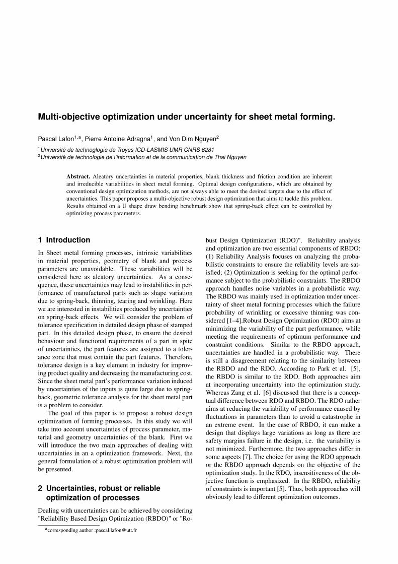
The case study in this paper is a benchmark problem ofNUMISHEET 2011 which the springback behavior of ad-vanced high strength steels of DP780 steel in U-shapeddraw bending is investigated [8]. The DP780 steel sheetwith 1.4 mm thick, 360 mm long and 30 mm wide is con-sidered. Experiments show that part profiles remain sym-metric through the manufacturing process (see Fig. 1).
�
CHAPTER 4
BM4 í Pre-strain Effect on Spring-back of 2-D Draw Bending
Provided by Seoul National University (Korea)
Contact Kwansoo Chung Seoul National University Korea [email protected] Toshihiko Kuwabara Tokyo University of Agriculture and Technology Japan [email protected] Rahul K. Verma TATA Steel India [email protected] Taejoon Park Seoul National University Korea [email protected] Hoon Huh KAIST (Korea Advanced Institute of Science and Technology) Korea [email protected] Gihyun Bae KAIST (Korea Advanced Institute of Science and Technology) Korea [email protected]
Figure 1. Effects of spring-back on U-shape drawing
Z
XY
rp
Blank Holder
rd
#–
FBHF
E,µ,Re,Rm
punch
die
Plane of symetry
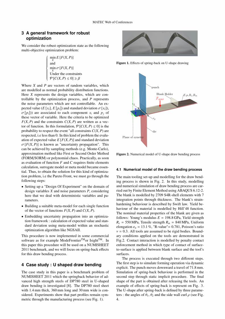
Figure 2. Numerical model of U-shape draw bending process
4.1 Numerical model of the draw bending process
The main tooling set-up and modelling for the draw bend-ing process is shown in Fig. 2. In this study, modellingand numerical simulation of draw bending process are car-ried out by Finite Element Method using ABAQUS 6.12-2.The blank is modelled by 2709 S4R-shell elements with 7integration points through thickness. The blank’s strain-hardening behaviour is described by Swift law. Yield be-haviour of the material is modelled by Hill’48 function.The nominal material properties of the blank are given asfollows: Young’s modulus E = 198.8 GPa, Yield strengthRe = 550 MPa, Tensile strength Rm = 840 MPa, Uniformelongation εu = 13.1 %, "R-value"= 0.781, Poisson’s ratioν = 0.3. All tools are assumed to be rigid bodies. Bound-ary conditions applied on the tools are demonstrated inFig.2. Contact interaction is modelled by penalty contactenforcement method in which type of contact of surface-to-surface is applied between blank surface and the tool’ssurfaces.
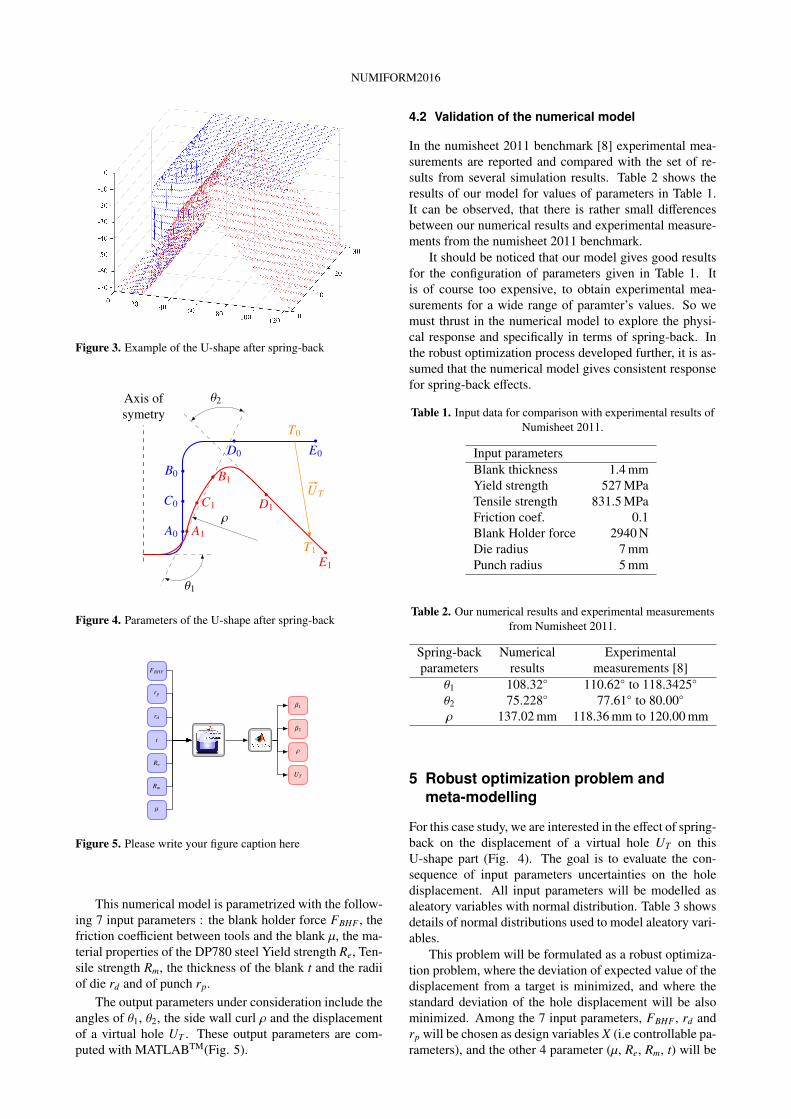
The process is executed through two different steps.The first step is to simulate forming operation via dynamicexplicit. The punch moves downward a travel of 71.8 mm.Simulation of spring-back behaviour is performed in thesecond step through static implicit procedure. The finalshape of the part is obtained after releasing the tools. Anexample of effects of spring-back is represent on Fig. 3.The U-shape after spring-back is defined by three parame-ters : the angles of θ1, θ2 and the side wall curl ρ (see Fig.4.
NUMIFORM2016
Figure 3. Example of the U-shape after spring-back
A0
C0
B0
D0 E0
A1
C1
B1
D1
E1
Axis ofsymetry
ρ
θ1
θ2
#–UT
T0
T1
Figure 4. Parameters of the U-shape after spring-back
t
rd
rp
FBHF
Re
Rm
µ
β2
β1
ρ
UT
Figure 5. Please write your figure caption here
This numerical model is parametrized with the follow-ing 7 input parameters : the blank holder force FBHF , thefriction coefficient between tools and the blank µ, the ma-terial properties of the DP780 steel Yield strength Re, Ten-sile strength Rm, the thickness of the blank t and the radiiof die rd and of punch rp.
The output parameters under consideration include theangles of θ1, θ2, the side wall curl ρ and the displacementof a virtual hole UT . These output parameters are com-puted with MATLABTM(Fig. 5).
4.2 Validation of the numerical model
In the numisheet 2011 benchmark [8] experimental mea-surements are reported and compared with the set of re-sults from several simulation results. Table 2 shows theresults of our model for values of parameters in Table 1.It can be observed, that there is rather small differencesbetween our numerical results and experimental measure-ments from the numisheet 2011 benchmark.
It should be noticed that our model gives good resultsfor the configuration of parameters given in Table 1. Itis of course too expensive, to obtain experimental mea-surements for a wide range of paramter’s values. So wemust thrust in the numerical model to explore the physi-cal response and specifically in terms of spring-back. Inthe robust optimization process developed further, it is as-sumed that the numerical model gives consistent responsefor spring-back effects.
Table 1. Input data for comparison with experimental results ofNumisheet 2011.
Input parametersBlank thickness 1.4 mmYield strength 527 MPaTensile strength 831.5 MPaFriction coef. 0.1Blank Holder force 2940 NDie radius 7 mmPunch radius 5 mm
Table 2. Our numerical results and experimental measurementsfrom Numisheet 2011.
Spring-back Numerical Experimentalparameters results measurements [8]
θ1 108.32◦ 110.62◦ to 118.3425◦
θ2 75.228◦ 77.61◦ to 80.00◦
ρ 137.02 mm 118.36 mm to 120.00 mm
5 Robust optimization problem andmeta-modelling
For this case study, we are interested in the effect of spring-back on the displacement of a virtual hole UT on thisU-shape part (Fig. 4). The goal is to evaluate the con-sequence of input parameters uncertainties on the holedisplacement. All input parameters will be modelled asaleatory variables with normal distribution. Table 3 showsdetails of normal distributions used to model aleatory vari-ables.
This problem will be formulated as a robust optimiza-tion problem, where the deviation of expected value of thedisplacement from a target is minimized, and where thestandard deviation of the hole displacement will be alsominimized. Among the 7 input parameters, FBHF , rd andrp will be chosen as design variables X (i.e controllable pa-rameters), and the other 4 parameter (µ, Re, Rm, t) will be
MATEC Web of Conferences
Table 3. Probabilistic modelling and representation ofuncertainties in the input parameters
Param. Unit Dist. Std. dev. Admissibleσ Mean val.
FBHF kN Normal 0.6667 2.94–50rd mm Normal 0.0167 2–10rp mm Normal 0.0167 2–10Re MPa Normal 16.667 500–600Rm MPa Normal 20 780–900µ Normal 0.0033 0.04–0.16t mm Normal 0.0167 1–2
considered as noise parameters P (i.e. uncontrollable pa-rameters). This robust optimization problem can be statedas:
minX|E [UT (X, P)] − UCible
T |
andmin
Xσ [UT (X, P)]
with :{
X ={FBHF , rd, rp
}P = {Re,Rm, t, µ}
The evaluation of the displacement of the virtual hole UT
for a (X, P) is based on the numerical model as presentedpreviously and requires 2.5 h of calculation on a worksta-tion running at 2.4 GHz.
In order to solve this optimization problem it is neces-sary to build a meta-model and set up an Design Of Ex-periment. We have defined a DOE based on a full factorialDOE with 3 levels for 7 parameters along a DOE of 2 sup-plementary levels for 2 parameters (FBHF , µ). The overallDOE represent 37 + (35 × 22) = 3159 numerical simula-tions (see Table 4). The huge amount of simulations hasbeen ran on a parallel computer with 1600 CPU’s.
Table 4. Factors and levels for the DOE
Param. levelsFBHF 2.94, 14.705, 26.47, 38.325 , 50 kNrd 2, 6 , 10 mmrp 2, 6 , 10 mmRe 500, 550 , 600 MPaRm 780, 840 , 900 MPaµ 0.04, 0.07, 0.1, 0.13 , 0.16t 1, 1.5 , 2 mm
Table 5. Comparison of accuracy of meta-models for UT
Meta-model MAE R2
Kriging 1.0258 × 10⁻⁴ 0.9999SVD2 36.6112 0.8268SVD3 38.6366 0.9370RBF 5.7494 × 10⁻¹⁰ 1NN 16.9244 0.9988
Here several meta-models have been tested. The twometrics which are used to measure the meta-models’ accu-racy are the R-square (R2) and the MAE.
MAE = max |yi − yi|, i = 1 . . .m
δ : deviation from target0 1 2 3 4 5 6 7 8 9 10 11 12 13 14 15 16 17
σ :
sta
nd
ard
de
via
tio
n
0.4
0.5
0.6
0.7
0.8
0.9
1
1.1
1.2
1.3
1.4
1.5
1.6
P2
P1
UT : Displacement of the virtual hole
Solution from NSGA IIPareto FrontAnchor pts
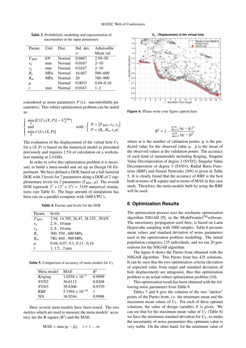
Figure 6. Please write your figure caption here
R2 = 1 −∑m
i=1 (yi − yi)2∑mi=1 (yi − y)2
where m is the number of validation points; yi is the pre-dicted value for the observed value yi. y is the mean ofthe observed values at the validation points. The accuracyof each kind of metamodels including Kriging, SingularValue Decomposition of degree 2 (SVD2), Singular ValueDecomposition of degree 3 (SVD3), Radial Basis Func-tions (RBF) and Neural Networks (NN) is given in Table5. It is clearly found that the accuracy of RBF is the bestboth in terms of R-square and in terms of MAE in this casestudy. Therefore, the meta-models built by using the RBFwill be used.
6 Optimization Results
The optimization process uses the stochastic optimizationalgorithm NSGAII [9], in the ModeFrontierTMsoftware.The uncertainty propagation used here, is based on LatinHypercube sampling with 1000 samples. Table 6 presentsmean values and standard deviation of noise parametersused in the optimization problem modelling. The initialpopulation comprises 125 individuals, and we ran 20 gen-erations for the NSGAII algorithm.
The figure 6 shows the Pareto front obtained with theNSGAII algorithm. This Pareto front has 425 solutions.It can be seen that the two optimization criteria (deviationof expected value from target and standard deviation ofhole displacement) are antagonist, thus this optimizationproblem is an actual robust optimization problem [10].
This optimization result has been obtained with the fol-lowing noise parameters from Table 6.
Tables 7 and 8 give the solution of the two "anchor"points of the Pareto front, i.e. the minimum mean and themaximum mean values of UT . For each of these optimalsolutions, the value of design variables X is given. Wecan see that for the maximum mean value of UT (Table 8)we have the minimum standard deviation for UT , so underthe uncertainty of noise parameters this optimum value isvery stable. On the other hand, for the minimum value of
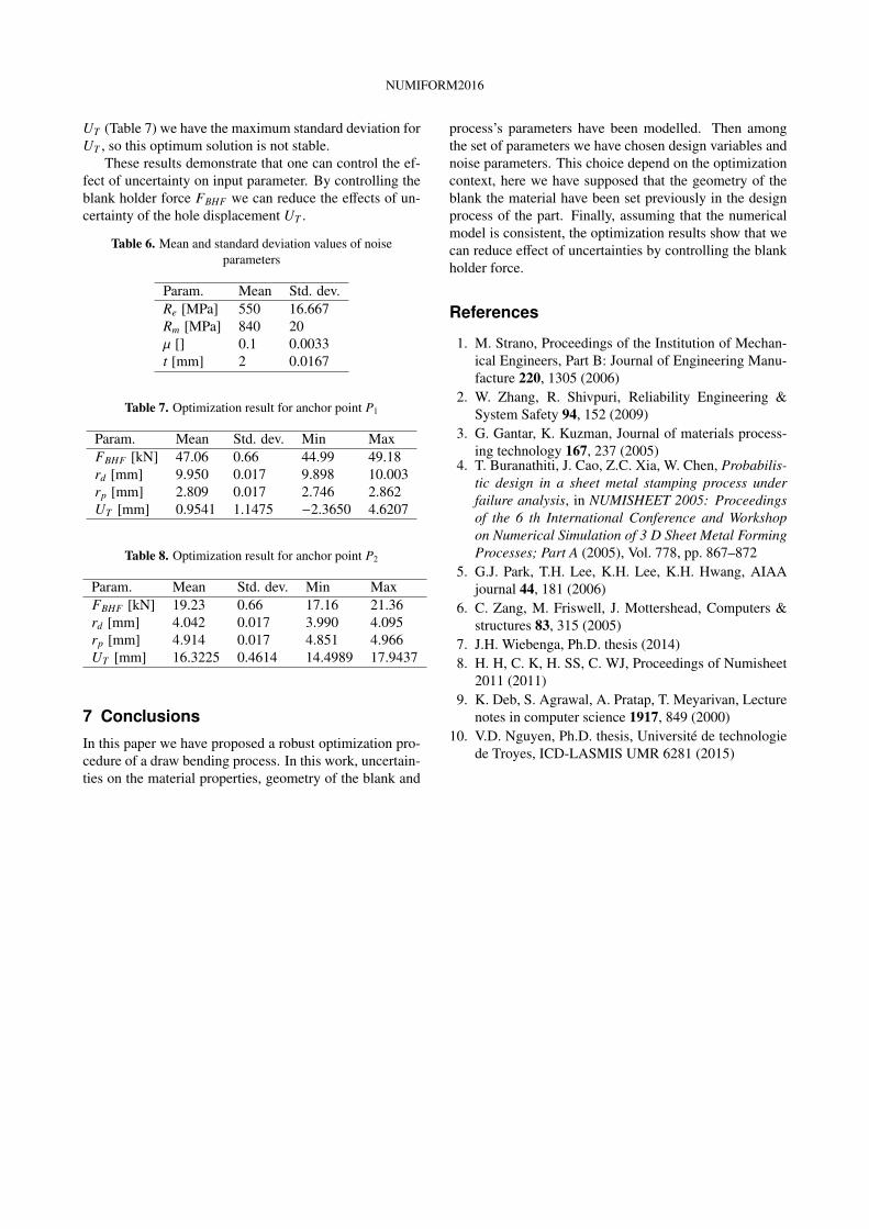
NUMIFORM2016
UT (Table 7) we have the maximum standard deviation forUT , so this optimum solution is not stable.
These results demonstrate that one can control the ef-fect of uncertainty on input parameter. By controlling theblank holder force FBHF we can reduce the effects of un-certainty of the hole displacement UT .
Table 6. Mean and standard deviation values of noiseparameters
Param. Mean Std. dev.Re [MPa] 550 16.667Rm [MPa] 840 20µ [] 0.1 0.0033t [mm] 2 0.0167
Table 7. Optimization result for anchor point P1
Param. Mean Std. dev. Min MaxFBHF [kN] 47.06 0.66 44.99 49.18rd [mm] 9.950 0.017 9.898 10.003rp [mm] 2.809 0.017 2.746 2.862UT [mm] 0.9541 1.1475 −2.3650 4.6207
Table 8. Optimization result for anchor point P2
Param. Mean Std. dev. Min MaxFBHF [kN] 19.23 0.66 17.16 21.36rd [mm] 4.042 0.017 3.990 4.095rp [mm] 4.914 0.017 4.851 4.966UT [mm] 16.3225 0.4614 14.4989 17.9437
7 Conclusions
In this paper we have proposed a robust optimization pro-cedure of a draw bending process. In this work, uncertain-ties on the material properties, geometry of the blank and
process’s parameters have been modelled. Then amongthe set of parameters we have chosen design variables andnoise parameters. This choice depend on the optimizationcontext, here we have supposed that the geometry of theblank the material have been set previously in the designprocess of the part. Finally, assuming that the numericalmodel is consistent, the optimization results show that wecan reduce effect of uncertainties by controlling the blankholder force.
References
1. M. Strano, Proceedings of the Institution of Mechan-ical Engineers, Part B: Journal of Engineering Manu-facture 220, 1305 (2006)
2. W. Zhang, R. Shivpuri, Reliability Engineering &System Safety 94, 152 (2009)
3. G. Gantar, K. Kuzman, Journal of materials process-ing technology 167, 237 (2005)
4. T. Buranathiti, J. Cao, Z.C. Xia, W. Chen, Probabilis-tic design in a sheet metal stamping process underfailure analysis, in NUMISHEET 2005: Proceedingsof the 6 th International Conference and Workshopon Numerical Simulation of 3 D Sheet Metal FormingProcesses; Part A (2005), Vol. 778, pp. 867–872
5. G.J. Park, T.H. Lee, K.H. Lee, K.H. Hwang, AIAAjournal 44, 181 (2006)
6. C. Zang, M. Friswell, J. Mottershead, Computers &structures 83, 315 (2005)
7. J.H. Wiebenga, Ph.D. thesis (2014)8. H. H, C. K, H. SS, C. WJ, Proceedings of Numisheet
2011 (2011)9. K. Deb, S. Agrawal, A. Pratap, T. Meyarivan, Lecture
notes in computer science 1917, 849 (2000)10. V.D. Nguyen, Ph.D. thesis, Université de technologie
de Troyes, ICD-LASMIS UMR 6281 (2015)
![Iterative surrogate model development...Iterativesurrogate model development with applications to multi‐objective design under uncertainty [and stochastic sampling] Alexandros Taflanidis](https://static.fdocuments.net/doc/165x107/5ed18edc2bcfc25a3212c644/iterative-surrogate-model-development-iterativesurrogate-model-development-with.jpg)