
MULTI OBJECTIVE OPTIMIZATION OF WASTE HEAT RECOVERY …
15
Journal of Thermal Engineering, Vol. 6, No. 4, pp. 604-618, July, 2020 Yildiz Technical University Press, Istanbul, Turkey MULTI OBJECTIVE OPTIMIZATION OF WASTE HEAT RECOVERY IN CEMENT INDUSTRY (A CASE STUDY) Mostafa Mostafavi Sani 1 , Alireza Noorpoor 1,* , Majid Shafiepour Motlagh 1 ABSTRACT Cement plants have the potential points to waste heat recovery. The method studied in this paper is based on the use of air quenching chamber (AQC) and suspension preheater (SP) Boilers which are installed at the output of the clean cooler and preheating stage respectively in Cement Plant. Due to the low temperature of the existed gases, three different fluids, water, R123 and R245fa are used as the working fluids and are evaluated in a similar cycle in terms of energy, exergy and the optimum parameters selection based on genetic algorithm. The results of this study showed that fluid R123 with optimized parameters leads to a 4% increase the total exergy loss and also will increase the production power from 5 MW to 9 MW. That is while in the case of water production power is increased from 4.8 to 5 MW is optimal state. Also the Results showed that the cost of produced electricity and exergy efficiency are lower in the case of organic fluid application in comparison with water as working fluid. Keywords: Exergy, Thermo-economic, Organic Rankine Cycle, Cement Industry, Genetic Algorithm INTRODUCTION World natural gas consumption rise by 1.7% in 2015. Among appearing economies, Iran (+6.2%) recorded the biggest growths to consumption [1]. Although Iran is the 3rd country in possessing fossil fuels terms (oil, gas and coal) whole the world, it is in 11th place of consumers of primary energy and 26th place of Gross Domestic Product (GDP) by consumption of 1973 MBOE (Million Barrels of Oil Equivalent) [1] and having GDP of 482 b$ US in all of the world. This shows high energy intensity of this nation [2]. Simultaneously cement industry is one of the highest energy consumption industries, like calcinations, drying and Kiln process needs large amounts of heat. Recently, the use of energy-saving techniques that contribute to the economy benefits and reduce the problems related to the environment is enhanced. With consideration Iran and world average energy intensities, the cement industries of Iran energy intensity are about 1.28 times of the average of all over the world. Output of cement was 80 Mt/y in 2015. There are already many developments and new-builds. Production was projected to growth to 90 Mt/y up to 2020 [3]. Based on Iran's administrations for "Rectification of Energy Consumption", up to 2021 it should minimize 50% compared to the energy intensity of the year 2011. The end users of energy because of bigness are: industries, buildings, transportation, and agriculture. With concentrate on the industry sector Iran has the potential of energy saving of 159 MBOE/year [2]. As a matter of fact, this potential can be an opportunity for promotion of Energy Service companies especially in the industry section. Potential of energy saving based on industrial standard development cement is (MBOE/Year) 2.2 and CO2 decline is 0.8 MT/ Year [2]. Recently, research associated to waste heat recovery has increased. Waste heat recovery not only reduces the demand of the fossil fuels, but also reduces the greenhouse gases and contributes to supply a more sustainable environment for the future. It has been argued that low grade waste thermal energy, less than 200 °C, represented a permanent resource of a growing concern because of its enlargement [4]. In the past fifty years, vast research has been done on the Organic Rankine Cycle (ORC) technology; recently, various industries were interested in using it. Some researchers have studied the effect of water on waste heat recovery of the Organic Rankine Cycle [5-10]. Using the heat of hot exhausted gas from the engine and by combining it with ORC, fuel conversion efficiency is promoted by an average of 7 percent. However, the NOx and CO2 production is decreased by 18 percent. Mago and et al studied an analysis of the This paper was recommended for publication in revised form by Regional Editor Hamadiche Mahmoud 1 School of Environment, College of Engineering, University of Tehran, Tehran, Iran. *Email: [email protected] Orcid id: 0000-0003-2976-7013, 0000-0002-8585-8852, 0000-0002-3624-2939 Manuscript Received 30 August 2018, Accepted 7 September 2018
Transcript of MULTI OBJECTIVE OPTIMIZATION OF WASTE HEAT RECOVERY …

Journal of Thermal Engineering, Vol. 6, No. 4, pp. 604-618, July, 2020 Yildiz Technical University Press, Istanbul, Turkey
MULTI OBJECTIVE OPTIMIZATION OF WASTE HEAT RECOVERY IN CEMENT INDUSTRY (A CASE STUDY)
Mostafa Mostafavi Sani1, Alireza Noorpoor1,*, Majid Shafiepour Motlagh1
ABSTRACT Cement plants have the potential points to waste heat recovery . The method studied in this paper is based
on the use of air quenching chamber (AQC) and suspension preheater (SP) Boilers which are installed at the output of the clean cooler and preheating stage respectively in Cement Plant. Due to the low temperature of the existed gases, three different fluids, water, R123 and R245fa are used as the working fluids and are evaluated in a similar cycle in terms of energy, exergy and the optimum parameters selection based on genetic algorithm. The results of this study showed that fluid R123 with optimized parameters leads to a 4% increase the total exergy loss and also will increase the production power from 5 MW to 9 MW. That is while in the case of water production power is increased from 4.8 to 5 MW is optimal state. Also the Results showed that the cost of produced electricity and exergy efficiency are lower in the case of organic fluid application in comparison with water as working fluid.
Keywords: Exergy, Thermo-economic, Organic Rankine Cycle, Cement Industry, Genetic Algorithm
INTRODUCTION World natural gas consumption rise by 1.7% in 2015. Among appearing economies, Iran (+6.2%) recorded
the biggest growths to consumption [1]. Although Iran is the 3rd country in possessing fossil fuels terms (oil, gas and coal) whole the world, it is in 11th place of consumers of primary energy and 26th place of Gross Domestic Product (GDP) by consumption of 1973 MBOE (Million Barrels of Oil Equivalent) [1] and having GDP of 482 b$ US in all of the world. This shows high energy intensity of this nation [2]. Simultaneously cement industry is one of the highest energy consumption industries, like calcinations, drying and Kiln process needs large amounts of heat. Recently, the use of energy-saving techniques that contribute to the economy benefits and reduce the problems related to the environment is enhanced. With consideration Iran and world average energy intensities, the cement industries of Iran energy intensity are about 1.28 times of the average of all over the world. Output of cement was 80 Mt/y in 2015. There are already many developments and new-builds. Production was projected to growth to 90 Mt/y up to 2020 [3]. Based on Iran's administrations for "Rectification of Energy Consumption", up to 2021 it should minimize 50% compared to the energy intensity of the year 2011. The end users of energy because of bigness are: industries, buildings, transportation, and agriculture. With concentrate on the industry sector Iran has the potential of energy saving of 159 MBOE/year [2]. As a matter of fact, this potential can be an opportunity for promotion of Energy Service companies especially in the industry section. Potential of energy saving based on industrial standard development cement is (MBOE/Year) 2.2 and CO2 decline is 0.8 MT/ Year [2]. Recently, research associated to waste heat recovery has increased. Waste heat recovery not only reduces the demand of the fossil fuels, but also reduces the greenhouse gases and contributes to supply a more sustainable environment for the future. It has been argued that low grade waste thermal energy, less than 200 °C, represented a permanent resource of a growing concern because of its enlargement [4]. In the past fifty years, vast research has been done on the Organic Rankine Cycle (ORC) technology; recently, various industries were interested in using it. Some researchers have studied the effect of water on waste heat recovery of the Organic Rankine Cycle [5-10]. Using the heat of hot exhausted gas from the engine and by combining it with ORC, fuel conversion efficiency is promoted by an average of 7 percent. However, the NOx and CO2 production is decreased by 18 percent. Mago and et al studied an analysis of the
This paper was recommended for publication in revised form by Regional Editor Hamadiche Mahmoud 1School of Environment, College of Engineering, University of Tehran, Tehran, Iran.*Email: [email protected] id: 0000-0003-2976-7013, 0000-0002-8585-8852, 0000-0002-3624-2939Manuscript Received 30 August 2018, Accepted 7 September 2018

Journal of Thermal Engineering, Research Article, Vol. 6, No. 4, pp. 604-618, July, 2020
605
regenerative Organic Rankine Cycles Using dry organic fluids to change wasted energy to product power from low-grade heat sources [11]. Yari investigated a study of the arrangement of ORC in geothermal resources based on the exergy analysis to select the best formation [12]. This study was carried out based on the rate of exergy loss and efficiency of first and second law that the ORC and internal heat exchanger was determined as the best cycle based on the first law of thermodynamics while R123 is the working fluid. Marco Astolfi and et al. presented a binary ORC to use low temperature geothermal resources [13]. Thermodynamic optimization results demonstrate that in those configurations which are based on the supercritical cycle, practical fluids with a little lower critical temperature than the geothermal resources temperature, represent highest efficiency for most of the cases. J. Wang and et al. investigated recover the exhaust gas heat of preheater and clinker cooler in cement plant have used single-pressure cycle, Kalina cycle, double vapor pressure cycle and ORC [14]. In a same expression, the optimal parameters resulted by Genetic Algorithm optimization were considered in order to gain the highest exergy efficiency. The results displayed that the exergy losses in the turbine, condenser and heat recovery vapor generator are high, and the exergy loss of these components can promote the efficiency of cogeneration systems. The Kalina cycle can get the best efficiency in the cement plant through other systems. F. Campana and et al. presented the first general evaluation of ORC module based on an exact measure for operating plants, such as cement, steel, glass, and oil and gas industries in 27 Europe Union countries [15]. Evaluation of energy savings was based on the number of work life, the decrease of CO2 emissions and electricity generation and utilization. This study showed that more than 20000 GWh/year of heat energy can be saved and 7.6 ton of CO2 can be recovered with the use of ORC technology. Based on the Best Available Technique References (BREF) in the cement industry, the best cycles for heat recovery could be ORC and steam cycle technology [15]. Simin Anvari et al. reviewed regeneration ORC has been applied to recover gas turbine's heat using HRSG [16]. Results showed that the first and second thermodynamic efficiencies in cycle with regeneration instead of reheat cycle has raised 2.62% and 2.6%, respectively. Also, sensitivity analysis demonstration that as gas turbine and combustion chamber inlet temperatures become greater, energetic and exergetic efficiencies become increase. Moreover, once condenser and evaporator temperature enhance, a slight reduction in energetic and exergetic efficiency is attended. Dan Song and Bin Chen provided a primery frame for exergy analysis of the cement generation plan [17]. Compared with the offered scenarios, an optimized method of sustainable development of cement industry was expected to be found out in the future. The framework may develop on the minimizing environmental effect and optimizing energy efficiency for cement manufacture. Daniel L. Summerbell et al. considered a case study of a plant in the UK, operating a pre-calciner type kiln commissioned in 1986 [18]. The paper concludes that there is significant opportunity to decline the emissions from cement plants by operational means and that fuel mix and excess air ratio should be the concentrate on future research. Optimizing the factors affecting performance was predicted to decrease energy utilization by 8.5% and CO2 emissions by 19.5%. In another paper, Madlool performed a model of a promoted four-stage suspension cyclone preheater system [19]. This sample was used to study the effect of waste preheater gas and dust bypass systems on preheater efficiency and performance. The results display that the calcination degree is reciprocally proportional to the heat amount of waste preheater bypass gases. As long as increasing of bypass opening at constant the content of dust kiln gas will cause reducing of waste heat amount of kiln gases. Madlool et al. reviewed the exergy, exergoeconomic and exergoenvironmental analyses of the ORC cycle with examined working fluids [20]. The multi-objective optimization is considered to get the system optimal operating conditions. The optimization investigates the exergy efficiency, the cost and the environmental impact per exergy unit of the net generated power as the objective functions. N.A. Madlool et al. reviewed exergy balance and exergy analysis for cement plants [21]. It is found that the exergy efficiency for cement units ranges from 18% to 49%. Also the exergy destraction because of the irreversibility from kiln are higher than other plants in cement production units. In this paper, a thermo-economic modeling and analysis of ORC and Rankine cycle for waste heat recovery, this equipment is optimized to get the greatest annual cost and thermal efficiency. Applying genetic algorithms the optimal points that is recognized as optimal front pareto, can be introduced.
As a summary, main features in this paper are as follow: • 3-function analysis system that includes energy, efficiency, and economy is set for the system.
Journal of Thermal Engineering, Research Article, Vol. 6, No. 4, pp. 604-618, July, 2020
606
• The selection of the temperature difference pinch point, the evaporator pressure, flow rate of ORC working fluid, as design parameters.
• Applying ORC multi-objective optimization with exergy efficiency and electricity prices as two objects. • The assessment of parameters in the optimization mode of the design mode. MATERIALS AND METHODS Energy Analysis
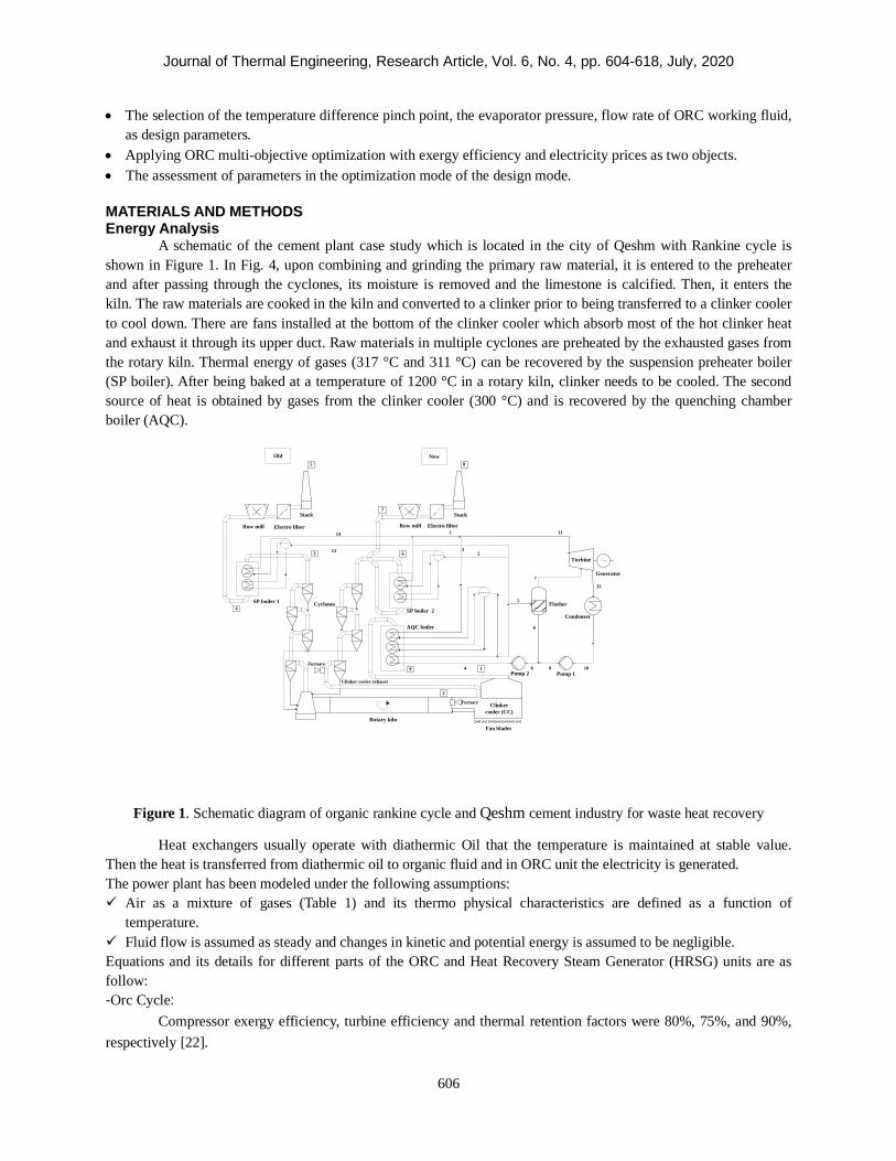
A schematic of the cement plant case study which is located in the city of Qeshm with Rankine cycle is shown in Figure 1. In Fig. 4, upon combining and grinding the primary raw material, it is entered to the preheater and after passing through the cyclones, its moisture is removed and the limestone is calcified. Then, it enters the kiln. The raw materials are cooked in the kiln and converted to a clinker prior to being transferred to a clinker cooler to cool down. There are fans installed at the bottom of the clinker cooler which absorb most of the hot clinker heat and exhaust it through its upper duct. Raw materials in multiple cyclones are preheated by the exhausted gases from the rotary kiln. Thermal energy of gases (317 °C and 311 °C) can be recovered by the suspension preheater boiler (SP boiler). After being baked at a temperature of 1200 °C in a rotary kiln, clinker needs to be cooled. The second source of heat is obtained by gases from the clinker cooler (300 °C) and is recovered by the quenching chamber boiler (AQC).
E -57
SP boiler 2
AQC boiler
Cyclones
Stack
Electro filterRow mill
Rotary kiln
Clinker cooler (CC)
Clinker cooler exhaustPump 1Pump 2
Condenser
Turbine
Flasher
Furnace
Furnace
Fan blades
Generator
1
23
4
5
7
8 9 10
11
6
12
Electro filterRow mill
6
E -72
3 13
14
Stack
4SP boiler 1
Old New
1
2
7
85
9
Figure 1. Schematic diagram of organic rankine cycle and Qeshm cement industry for waste heat recovery
Heat exchangers usually operate with diathermic Oil that the temperature is maintained at stable value. Then the heat is transferred from diathermic oil to organic fluid and in ORC unit the electricity is generated. The power plant has been modeled under the following assumptions: Air as a mixture of gases (Table 1) and its thermo physical characteristics are defined as a function of
temperature. Fluid flow is assumed as steady and changes in kinetic and potential energy is assumed to be negligible. Equations and its details for different parts of the ORC and Heat Recovery Steam Generator (HRSG) units are as follow: -Orc Cycle:
Compressor exergy efficiency, turbine efficiency and thermal retention factors were 80%, 75%, and 90%, respectively [22].

Journal of Thermal Engineering, Research Article, Vol. 6, No. 4, pp. 604-618, July, 2020
607
The mass balance equation:
Production or consumption power and disposed or absorbed heat by each of the cycle components are calculated using the first and second laws of thermodynamics. Energy balance equation is used as follow:
Energy balances for the turbine cycle (Figure 1) are as follows: -Evaporator:
-Turbine:
-Condenser:
Pressure drop in the evaporator ( p∆ ) were assumed as follows:
-Pump:
Heat Recovery Steam Generator (HRSG)
HRSG design in the project is based on pinch and approach point which by considering these parameters as input, steam flow rate is calculated. Also in the HRSG design the steam and water temperature graph is determined and the inlet and outlet temperature of the heat exchanger is determined. Finally, given the prevailing limits such as the temperature of the exhausted gases and the lack of steam generation in economizer and etc. the design will be completed [23, 24]. Both pinch points and approach points are considered in modeling.
(1) ∑∑ = oi mm
(2)
(3) )( ioievap hhmQ −=
(4) soi
aoi
sT
aTT hh
hhWW
,
,
,
,
−
−==
η
(5) ∑∑ −= ooiiaT hmhmW
,
(6) ∑∑ −= ooiicon hmhmQ
(7) )1(/ ppp io ∆−=
(8) io
ioi
ap
spp hh
PPWW
−−
==)(
,
, νη
∑∑ +=+oi
WEQE oi
Journal of Thermal Engineering, Research Article, Vol. 6, No. 4, pp. 604-618, July, 2020
608
Mass and energy balance equations for the economizer, evaporator and superheater are given below:
-Economizer:
-Evaporator:
-Super heater:
Exergy Analysis
In this paper, exergy at each point is a combination of physical and chemical exergy which is calculated according to the following equation [25-27]:
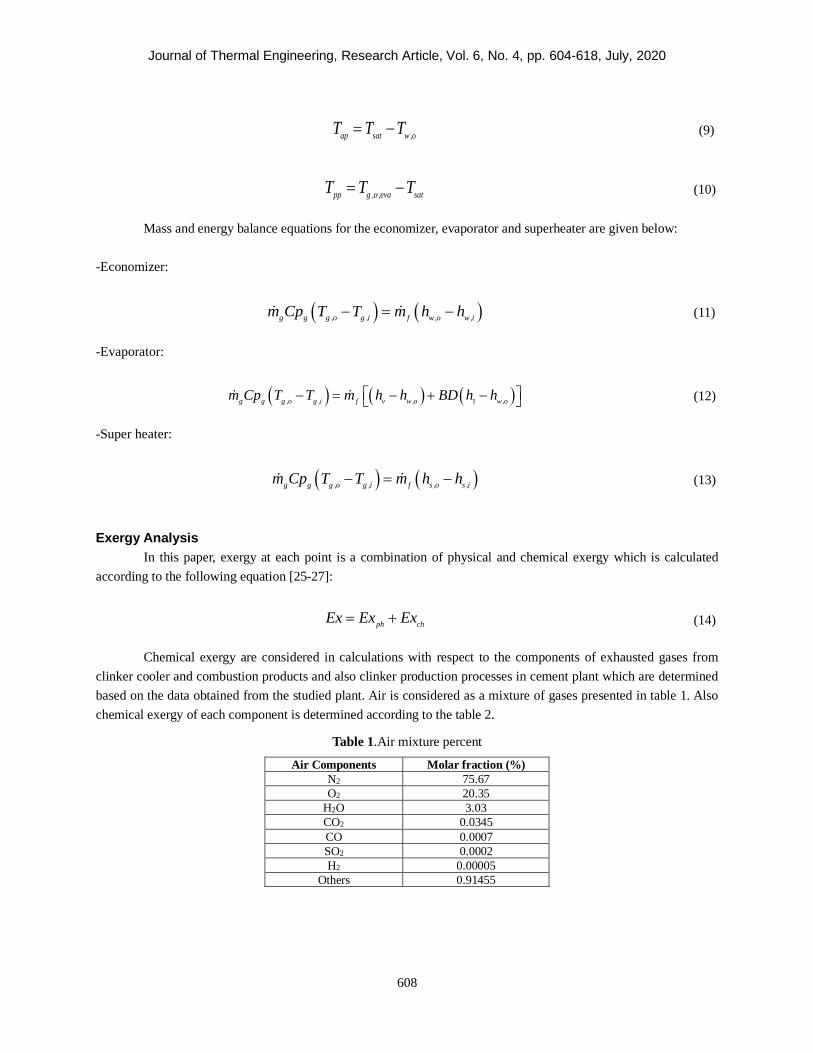
Chemical exergy are considered in calculations with respect to the components of exhausted gases from clinker cooler and combustion products and also clinker production processes in cement plant which are determined based on the data obtained from the studied plant. Air is considered as a mixture of gases presented in table 1. Also chemical exergy of each component is determined according to the table 2.
Table 1.Air mixture percent
Air Components Molar fraction (%) N2 75.67 O2 20.35
H2O 3.03 CO2 0.0345 CO 0.0007 SO2 0.0002 H2 0.00005
Others 0.91455
(9) ,ap sat w oT T T= −
(10) , ,pp g o eva satT T T= −
(11) ( ) ( ), , , ,g g g o g i f w o w im Cp T T m h h− = −
(12) ( ) ( ) ( ), , , 1 ,g g g o g i f v w o w om Cp T T m h h BD h h − = − + −
(13) ( ) ( ), , , ,g g g o g i f s o s im Cp T T m h h− = −
(14) ph chEx Ex Ex= +

Journal of Thermal Engineering, Research Article, Vol. 6, No. 4, pp. 604-618, July, 2020
609
Table 2. Chemical exergy and molar mass of the main composition of the kiln feed
Composition Molar mass Chemical exergy (Kj/Kmol)
2Ca.SiO2(C2S) 172.28 95700 3Ca.SiO2(C3S) 251.46 219800
3Ca.Al2O3(C3A) 270.3 500600 4Ca.Al2O3.Fe2O3(C4A) 486.1 66700
MgO 40.3 66800 CaSo4
136.166
8200
Exergy loss rate for each component is calculated according to the following equation [28]:
Also by defining the following parameter the rate of exergy loss to the total exergy loss can be achieved [28]:
Exergy efficiency of the cycle is calculated as follows [28]:
int,PlantEx is the resulted exergy from the outlet of clinker coolers and inlet preheater to the designed plant.
Economic Analysis
The economic analysis of each component is determined according to the following references [14] and [29]. A steadied electricity price over the 20 years is calculated as follows:
which
In Equation 18 i is inflation percent which is considered to be of 20% and N is useful life of plant and OM is the costs of maintenance per KWh. The cost of operation is intended 2% of the cost of the equipment. The cost of operation is considered to be 2% of the equipment cost [28-31]. Case Study
Qeshm cement Plant is located at 3 km southeast of the city of Qeshm, northern Iran, with two gray cement production line and nominal capacity of 4,000 and 3,000 tons of clinker per day. It took two year to finish a project
(15) i E D LEx Ex Ex Ex= + +
(16)
,
D
D
D Total
ExyEx
=
(17)
,
1 D L
ex
in Plant
Ex Ex
Exη +
= −
(18) (1 )
(1 ) 1Cos
N
plantN
i i Zit OM
E
++ −= +
(19) 6072
0( )out
tE Ex t t
== ∆∑

Journal of Thermal Engineering, Research Article, Vol. 6, No. 4, pp. 604-618, July, 2020
610
(started in 2008) to increase the capacity of the line 1 to reach 4000 tone clinker per day. To fulfill that, steel preheater with the inlet air flow from the Clinker cooler fan blades is applied. To reach the desired temperature, the air flow is heated by a torch which is installed under the preheater. Line 1 of the plant is studied in this paper as a case study (Table 3). The temperature profile of line 1 (Figure 1) is given in Table 4.
Table 3. Qeshm cement plant gas conditions
point Parameter Temperature (˚C) Mass flow rate (kg/s) 1 Clinker cooler exhaust 290 56.33 2
New preheater entrance 899 31 3
Old preheater exhaust 311 42 4
SP boiler 1 exhaust 215 42 5
stack exhaust 1 93 42 6
New preheater exhaust 317 62 7 SP boiler 2 exhaust 215 62 8 stack exhaust 2 99 62 9
AQC boiler exhaust 99 56.33
Table 4. Qeshm cement plant exhaust gas conditions
Parameters Value New preheater exhaust temperature (°C) 317 Old preheater exhaust temperature (°C) 311
SP boiler exhaust temperature (°C) 214 Clinker cooler exhaust temperature (°C) 290 New preheater exhaust mass flow (kg/s) 62 Old preheater exhaust mass flow (kg/s) 42 Clinker cooler exhaust mass flow (kg/s) 56
The Optimization Method (Genetic Algorithm)
Genetic Algorithm is a search method which is used for finding the exact or approximate solutions of the optimization problems. This method was first used by John Holland in 1960, and is now employed in many fields including engineering, chemistry, mathematics, physics, computational sciences, phylogenetic, etc. This algorithm is a special class of evolutionary algorithms, which have been inspired by evolutionary biology concepts such as inheritance, mutation, selection and crossover. The computational procedure in this algorithm includes the following steps [32, 33]:
1. Generating an initial population 2. Evaluating the fitness of each individual in the population 3. Repeating the optimization process until a termination cause is achieved (reaching the ultimate iteration limit, time constraint, objective function constraint, getting uniform solutions in successive generations (occurrence of pause), and time constraint of uniformity in generations, etc.): a) Selecting the best individual for reproduction b) Forming a new generation through crossover or mutation operations and reproducing the offspring c) Assessing the personal fitness of every offspring d) Replacing the population with lowest and worst rank by the offspring
RESULTS AND DISCUSSION
In the modeling, ORC and water cycle are suggested as upstream cycle to use the heat wasted from cement plant. Water, R123 and R245f as working, have been compared from energy and thermo-economic point of view. Also, considering the changes in parameters such as temperature, the main fluid pressure, condenser pressure and the outlet pressure of the flash, cycle optimization is discussed. Comparing the thermal balance of the steam cycle
Journal of Thermal Engineering, Research Article, Vol. 6, No. 4, pp. 604-618, July, 2020
611
and ORC cycles, it can be concluded that organic fluids due to its unique condition and characteristics could lead to a higher fluid flow which lead to a higher heat energy absorption of the gas in recovery boilers. Energy Analysis
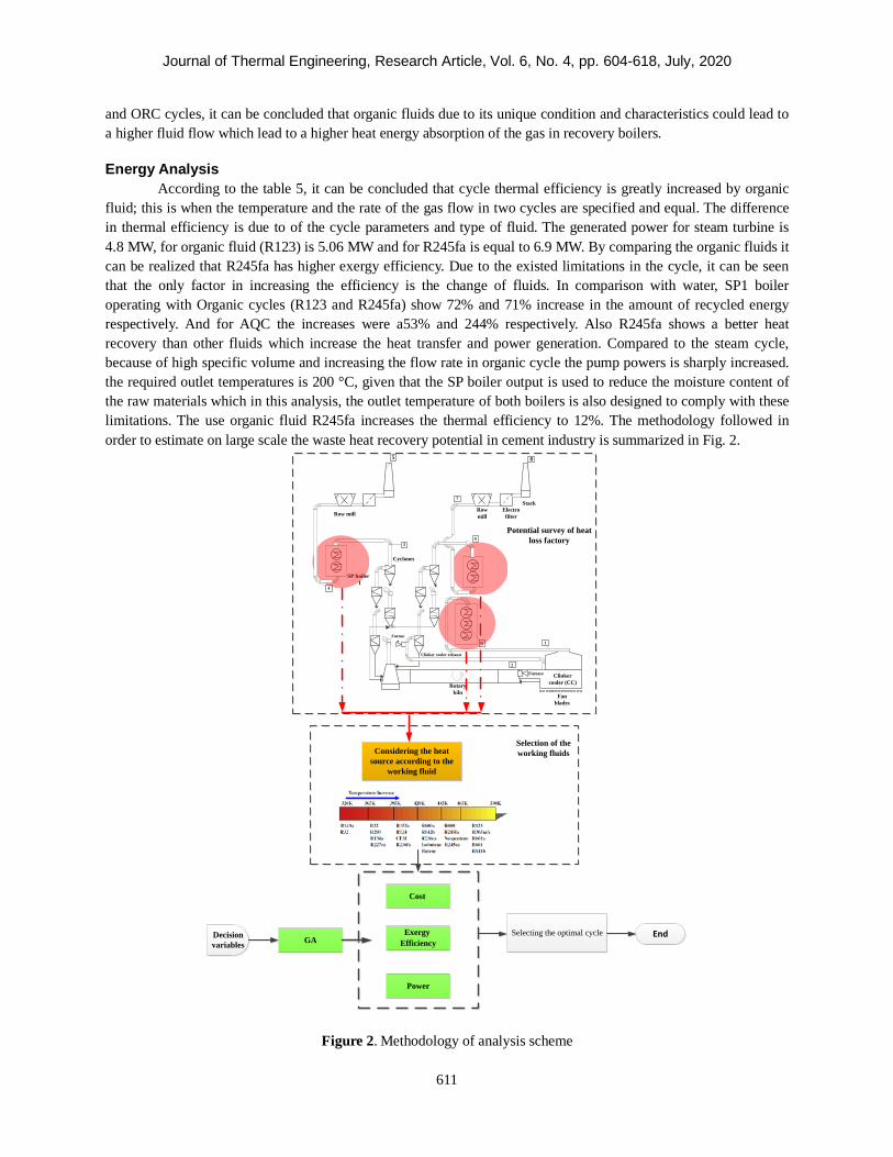
According to the table 5, it can be concluded that cycle thermal efficiency is greatly increased by organic fluid; this is when the temperature and the rate of the gas flow in two cycles are specified and equal. The difference in thermal efficiency is due to of the cycle parameters and type of fluid. The generated power for steam turbine is 4.8 MW, for organic fluid (R123) is 5.06 MW and for R245fa is equal to 6.9 MW. By comparing the organic fluids it can be realized that R245fa has higher exergy efficiency. Due to the existed limitations in the cycle, it can be seen that the only factor in increasing the efficiency is the change of fluids. In comparison with water, SP1 boiler operating with Organic cycles (R123 and R245fa) show 72% and 71% increase in the amount of recycled energy respectively. And for AQC the increases were a53% and 244% respectively. Also R245fa shows a better heat recovery than other fluids which increase the heat transfer and power generation. Compared to the steam cycle, because of high specific volume and increasing the flow rate in organic cycle the pump powers is sharply increased. the required outlet temperatures is 200 °C, given that the SP boiler output is used to reduce the moisture content of the raw materials which in this analysis, the outlet temperature of both boilers is also designed to comply with these limitations. The use organic fluid R245fa increases the thermal efficiency to 12%. The methodology followed in order to estimate on large scale the waste heat recovery potential in cement industry is summarized in Fig. 2.
Considering the heat source according to the
working fluid
E-57
Cyclones
Electro filter
Row mill
Rotary kiln
Clinker cooler (CC)
9
Clinker cooler exhaust
Furnace
Furnace
Fan blades
6
Row mill
3
E-72
4
Stack
SP boiler 1
7
5 8
1
2
Potential survey of heat loss factory
Selection of the working fluids
Cost
Exergy Efficiency
Power
Selecting the optimal cycle EndGADecision
variables
Figure 2. Methodology of analysis scheme
Journal of Thermal Engineering, Research Article, Vol. 6, No. 4, pp. 604-618, July, 2020
612
Exergy Analysis In this section the results of exergy analysis and exergy loss of each component of the water cycle and
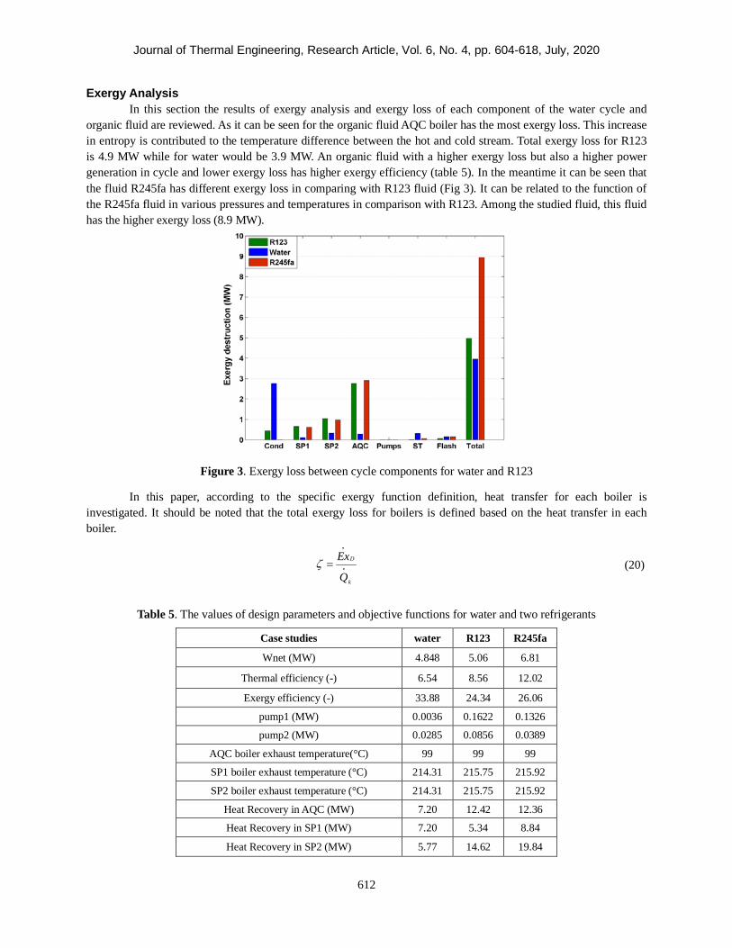
organic fluid are reviewed. As it can be seen for the organic fluid AQC boiler has the most exergy loss. This increase in entropy is contributed to the temperature difference between the hot and cold stream. Total exergy loss for R123 is 4.9 MW while for water would be 3.9 MW. An organic fluid with a higher exergy loss but also a higher power generation in cycle and lower exergy loss has higher exergy efficiency (table 5). In the meantime it can be seen that the fluid R245fa has different exergy loss in comparing with R123 fluid (Fig 3). It can be related to the function of the R245fa fluid in various pressures and temperatures in comparison with R123. Among the studied fluid, this fluid has the higher exergy loss (8.9 MW).
Figure 3. Exergy loss between cycle components for water and R123
In this paper, according to the specific exergy function definition, heat transfer for each boiler is investigated. It should be noted that the total exergy loss for boilers is defined based on the heat transfer in each boiler.
Table 5. The values of design parameters and objective functions for water and two refrigerants
Case studies water R123 R245fa
Wnet (MW) 4.848 5.06 6.81
Thermal efficiency (-) 6.54 8.56 12.02
Exergy efficiency (-) 33.88 24.34 26.06
pump1 (MW) 0.0036 0.1622 0.1326
pump2 (MW) 0.0285 0.0856 0.0389
AQC boiler exhaust temperature(°C) 99 99 99
SP1 boiler exhaust temperature (°C) 214.31 215.75 215.92
SP2 boiler exhaust temperature (°C) 214.31 215.75 215.92
Heat Recovery in AQC (MW) 7.20 12.42 12.36
Heat Recovery in SP1 (MW) 7.20 5.34 8.84
Heat Recovery in SP2 (MW) 5.77 14.62 19.84
(20) D
k
Ex
Qζ =

Journal of Thermal Engineering, Research Article, Vol. 6, No. 4, pp. 604-618, July, 2020
613
It can be concluded from the figure that heat transfer process in boilers for water shows a better function in comparison with organic fluid (Fig 4).
Figure 4. Comparison of the working fluid specific exergy (water and organic)
According to the Table 5 (recovered heat transfer) this amount is higher for organic fluid than for water. However, specific exergy value of organic fluid is higher due to greater exergy loss in these components. Figure 4 shows the ratio of exergy loss of components to total exergy. As it can be seen exergy loss in organic fluids allocate a greater region in comparison with water which can be contributed to the low operating temperature of the organic fluids. The point to note in this graph is the ration of turbine exergy loss to the total exergy loss. The steam quality of the turbine must be higher than 88% and this limitation leads to higher exergy loss to total exergy ratio in steam turbine in comparison with organic turbine. One of the advantages of using of organic Fluids is due to the related thermodynamic properties that can be used at lower pressure and without limitation.
Figure 5. The ratio of exergy loss of components to total exergy for different fluids
Journal of Thermal Engineering, Research Article, Vol. 6, No. 4, pp. 604-618, July, 2020
614
Economic Analysis Results The produced electricity costs have been calculated based on 6073 hours of operation per year in cement
plant. In the case of organic fluid, steam turbine and condenser and for water turbines and boilers have the highest costs in comparison with other components. In general, due to higher power productivity of the organic fluids, the end cost of electricity is lower than water and also R245fa has lower cost in comparison with R123.
The higher cost of organic fluid in the condenser can be contributed to the low surface tension when compared to water which considering the condensation, the use of fin and also the surface area extension (higher surface means higher cost) in these types of condensers are needed. On the other hand among the cycle components, pumps the least expensive. Low electricity costs reflect the efficient use of waste heat in the cycle which considering the use of heat exchangers and heat recovery boilers this energy can be used with minimum cost. Optimization Results (Two-Objective Optimization)
Exergy efficiency of the cycle and electricity cost are considered to be the objective functions. Optimizing curve for a working fluid is shown Figure 6.
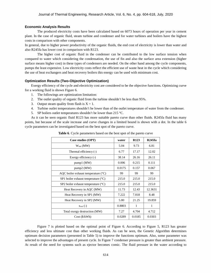
1. The followings are optimization limitation: 2. The outlet quality of organic fluid from the turbine shouldn’t be less than 95%. 3. Output steam quality from flash is X = 1. 4. Turbine outlet temperatures shouldn’t be lower than of the outlet temperature of water from the condenser. 5. SP boilers outlet temperatures shouldn’t be lower than 215 °C. As it can be seen organic fluid R123 has more suitable pareto curve than other fluids. R245fa fluid has many
points, but because of the scale increase and curve changes in a limited bound is shown with a dot. In the table 6 cycle parameters can be investigated based on the best spot of the pareto curve.
Table 6. Cycle parameters based on the best spot of the pareto curve
Case studies (OPT) water R123 R245fa
Wnet (MW) 5.04 9.73 6.81
Thermal efficiency (-) 6.77 17.17 12.02
Exergy efficiency (-) 38.14 26.16 26.11
pump1 (MW) 0.006 0.215 0.111
pump2 (MW) 0.0175 0.157 0.067
AQC boiler exhaust temperature (°C) 99 99 99
SP1 boiler exhaust temperature (°C) 215.0 215.0 215.0
SP2 boiler exhaust temperature (°C) 215.0 215.0 215.0
Heat Recovery in AQC (MW) 11.73 12.43 12.3631
Heat Recovery in SP1 (MW) 7.222 7.818 8.48
Heat Recovery in SP2 (MW) 5.80 21.25 19.859
xout (-) 0.8803 1 1
Total exergy destruction (MW) 7.27 4.704 4.712
Cost ($/kWh)
0.0289
0.0185
0.0303
Figure 7 is plotted based on the optimal point of Figure 6. According to Figure 5, R123 has greater
efficiency and less ultimate cost than other working fluids. As can be seen, the Genetic Algorithm determines optimum decision parameters (presented in Table 5) to improve the functions optimum. Also, some parameter was selected to improve the advantages of present cycle. In Figure 7 condenser pressure is greater than ambient pressure. At result of the need for systems such as ejector becomes comic. The fluid pressure in the water according to

Journal of Thermal Engineering, Research Article, Vol. 6, No. 4, pp. 604-618, July, 2020
615
vacuum the condenser to the air outlet and condensate process improvement ejector system is needed. No need for the system to reduce costs. Also according to the temperature of the fluid lies R123 29 in the condenser to reduce costs as well as factories making cement be used to remote areas of Ab¬Hay level of air-cooled condenser. due to lower energy and cooling water flow rate of a fluid heat exchanger for Ypsh used R123. Due to space restrictions in cement factories operate to the advantage of energy recovery system at the factory.
Figure 6. Optimal Pareto curves for different fluids
Figure 7 is plotted based on the optimal point (Figure 6). According to Figure 5, the R123 has the highest
efficiency and the lowest annual cost between fluids. As can be seen, the genetic algorithm leads to improve objective functions by determining the optimal decision points (presented in Table 5). Fig. 7 illustrates the final condenser pressure is higher than the ambient pressure (101 kPa). Also, using auxiliary systems such as ejector is ignored by choosing this pressure. While omitting of auxiliary condensate systems would be reduction in the amount of annual cost. Also, air cooled condenser is more practical, due to the temperature of R123 in the condenser is 29 ºC, as well as the location of cement factory is far away from the sea water. Moreover, the exhausted steam from turbine is still superheated which leads to a longer life span of the end rows of the turbine (Fig. 7). Due to the heat capacity of R123 is lower than water and with reducing difference between turbine inlet and outlet pressure, the number of turbine blades and its volume decreases. Therefore, this is an advantage to overcome the lack of space in cement factories.

Journal of Thermal Engineering, Research Article, Vol. 6, No. 4, pp. 604-618, July, 2020
616
Figure 7. T-S diagram for R123 in optimum point CONCLUSION
In this paper, an energy recovery system for Qeshm cement plant was modeled and the following results were obtained:
• The use of organic fluids can increase the thermal efficiency and power generation. In energy analysis it was found that due to the low yield of organic fluid, the obtained flow rate in boilers is greater than water. In organic cycle with R245fa and R123 as working fluids SP1 Boiler, compared to water shows a 72% and 71% increase in recycled energy and for AQC this increase is 153% and 244% respectively. Also in power generation R123 with 4% and R245fa with 28.8% increase, compared to water, benefit more from energy in a cycle with the same structure.
• The exergy analysis of the results showed that water has higher exergy efficiency in comparison with other organic fluids.
o Also turbine outlet steam quality limitation results in a higher exergy loss to total exergy ratio for steam (10%) than organic fluids (8%).
o By defining the specific exergy it can be seen that boilers with operating with water as working fluid show better performance in comparison with organic fluids.
• In the economic analysis because of the higher power generated by organic fluids during operation of the cement plant, electricity prices have fallen comparing with water.
• The obtained results from the genetic algorithm optimization has showed that in the desired cycle the parameters can have a major role in changing the fluid performance and have a great impact on the electricity prices and exergy efficiency. Based on the best point on the fluid pareto curve, with increase in power generation and decrease in electricity price, R123 can be considered a suitable fluid for cycle and show a 4.1% decrease in total exergy loss of the system.
NOMENCLATURE List of acronyms CCPP Combined-Cycle Power Plant CHP Combined Heat and Power CRF Capital Recovery Factor GT Gas Turbine
0.80 1.00 1.20 1.40 1.60 1.80
-50
0
50
100
150
200
s (kJ/kg-K)
T (°
C)
949.5 kPa
0.2 0.4 0.6 0.8
HPHPLPLP
694.9 kPa
103.4 kPa

Journal of Thermal Engineering, Research Article, Vol. 6, No. 4, pp. 604-618, July, 2020
617
LHV Lower Heat Value (kJ/kg) NG Natural Gas List of symbols Ex Exergy flow (kW) N Operation hours in a year mf Fuel flow rate (kg.s-1) Q Heat flow (kW) wp Pump Power (kW) Subscripts amb Ambient b Boiler CC Combustion Chamber ch Chemical D Distraction e Exergy h Heat Ph Physical ST Steam Turbine i Interest rate P Pump Greek symbols η Efficiency ρ Density (kg/ m3) ξ Chemical exergy/energy ratio
REFERENCES [1] BP Statistical Review of World Energy June 2016. [2] Avami A, Sattari S. Energy Conservation Opportunities: Cement Industry in Iran International journal of
energy. 2007;1:65-71. [3] Iran Cement Organization. Available from: http://irancement.com [4] Ziviani D, Beyene A, Venturini M. Advances and challenges in ORC systems modeling for low grade
thermal energy recovery. Applied Energy. 2014;121:79-95. [5] Wei D, Lu X, Lu Z, Gu J. Performance analysis and optimization of organic Rankine cycle (ORC) for waste
heat recovery. Energy Conversion and Management. 2007; 48:1113–1119. [6] Mago PJ, Louay M, Srinivasan K, Somayaji C. An examination of regenerative Rankine cycles using dry
fluids. Applied Thermal Engineering 2008; 28:998-1007. [7] Maizza V, Maizza A. Unconventional working fluids in organic rankine-cycles for waste energy recovery
systems. Applied Thermal Engineering 2001; 21:381-390 [8] Yari M. Performance analysis of the different organic Rankine cycles (ORCs) using dry fluids. International
Journal of Exergy. 2009; 6:323–342. [9] Chen Y, Lundqvist P, Johansson, A, Platell PA. Comparative study of the carbon dioxide trans-critical
power cycle compared with an organic Rankine cycle with r123 as working fluid in waste heat recovery. Applied Thermal Engineering. 2006; 26:2142–2147.
[10] Kalyan K, Srinivasan K, Pedro J, Krishnan R. Analysis of exhaust waste heat recovery from a dual fuel low temperature combustion engine using an organic Rankine cycle. Energy. 2010; 35:2387–2399.
[11] Mago PJ, Chamra LM, Srinivasan K, Somayaji C. An examination of regenerative organic rankine cycles using dry fluids. Applied Thermal Engineering. 2008; 28:998–1007.
[12] Yari M. Exergetic analysis of various types of geothermal power plants. Renewable Energy. 2010;35:112–121.

Journal of Thermal Engineering, Research Article, Vol. 6, No. 4, pp. 604-618, July, 2020
618
[13] Astolfi M, Matteo C, Romano M, Bombarda P, Macchi E. Binary ORC (organic Rankine cycles) power plants for the exploitation of medium low temperature geothermal sources. Energy. 2014; 66:423–434.
[14] Wang J, Dai Y, Gao L. Exergy analyses and parametric optimizations for different cogeneration power plants in cement industry. Applied Energy. 2009; 86:941–948.
[15] Campana F, Bianchi M, Branchini L, Pascale AD, Peretto A, Baresi M., Fermi A, Rossetti N, Vescovo R. ORC waste heat recovery in European energy intensive industries: Energy and GHG savings. Energy Conversion and Management. 2013; 76:244–252.
[16] Kerme E, Orfi J. Exergy-based thermodynamic analysis of solar driven organic rankine cycle. Journal of Thermal Engineering. 2015;1:192-202.
[17] Song D, Chen B. Extended exergy accounting for energy consumption and co2 emissions of cement industry-a basic framework. Applied Energy Symposium and Summit 2015: Low carbon cities and urban energy systems 2015.
[18] Summerbell DL. Barlow CY. Cullen JM. Potential reduction of carbon emissions by performance improvement: A cement industry case study. Journal of Cleaner Production. 2016;135:1327-1339.
[19] Madlool NA. Assessment of waste preheater gas and dust bypass systems: Al-Muthanna cement plant case study. Case Studies in Thermal Engineering. 2016; 8:330–336.
[20] Fergani Z, Touil D, Morosuk T. Multi-criteria exergy based optimization of an organic rankine cycle for waste heat recovery in the cement industry. Energy Conversion and Management. 2016;112:81–90.
[21] Madloola NA, Saidura R, Rahimb NA, Islama MR, Hossianb MS. An exergy analysis for cement industries: An overview. Renewable and Sustainable Energy Reviews. 2012; 16:921– 932.
[22] Sani MM, Noorpoor A, Motlagh MS. Design and optimization of an energy hub based on combined cycle power plant to improve economic and exergy objectives. Journal of Energy Equipment and Systems. 2020;9:1-22.
[23] Behbahaninia A, Bagheri M, Bahrampoury R. Optimization of fire tube heat recovery steam generators for cogeneration plants through genetic algorithm. Applied Thermal Engineering. 2010; 30:2378–2385.
[24] Esmaieli A, Keshavarz MP, Shakib SE, Amidpour M. Applying different optimization approaches to achieve optimal configuration of a dual pressure heat recovery steam generator. International Journal of energy Research. 2012; 10:1002-2944.
[25] Ghasemi A, Hashemian N, Noorpoor A, Heidarnejad, P. Exergy based optimization of a biomass and solar fueled CCHP hybrid seawater desalination plant. Journal of Thermal Engineering. 2017; 3:1034-1043.
[26] Ghasemi A, Heidarnejad P, Noorpoor A. A novel solar-biomass based multi-generation energy system including water desalination and liquefaction of natural gas system. Journal of Cleaner Production. 2018;196:424-437.
[27] Sengupta S, Datta A, Duttagupta S. Exergy analysis of a coal-based 210 MW thermal power plant. International Journal of Energy Research 2007; 31:14-28.
[28] Ameri M, Mokhtari H, Sani MM. 4E analyses and multi-objective optimization of different fuels application for a large combined cycle power plant. Energy. 2018;156: 371-386.
[29] Bejan A, Tsatsaronis G, Moran M. Thermal design and optimization. New York, Wiley, 1996. [30] Sani MM, Noorpoor A, Motlagh MS. Optimal model development of energy hub to supply water, heating
and electrical demands of a cement factory. Energy. 2019;177: 574-592. [31] Rosen M, Dincer I. Exergoeconomic analysis of power plants operating on various fuels. Applied Thermal
Engineering 2003; 23:643-58. [32] Esfahani JI., KyooYoo C. Feasibility study and performance assessment for the integration of a steam-
injected gas turbine and thermal desalination system. Desalination. 2014; 332:18–32. [33] Mokhtari H, Hadiannasab H, Mostafavi M. Determination of optimum geothermal Rankine cycle
parameters utilizing coaxial heat exchanger. Energy. 2016;102:260-275.