MULTI- MILLION DOLLAR INVENTORY IN SYSTEM & … · erection procedure nomenclature inspection of...
32
Stepup Scaffolding Los Angeles 3 Stepup Scaffolding Houston 4 STEPUP SCAFFOLDING canada 6 Stepup Scaffolding Atlanta 2 Stepup Scaffolding New York 5 1 Sunshine International Corp. (HQ) Memphis MULTI- MILLION DOLLAR INVENTORY IN SYSTEM & FRAME SCAFFOLD PRODUCTS INSURED BY A + RATED INSURANCE COMPANY U.S. LAB TESTED TO MEET & EXCEED OSHA & ANSI STANDARDS DISTRIBUTION NETWORK TOLL FREE: 1-888-STEPUP-1 WWW.STEPUPSCAFFOLD.COM A sunshine enterprise company 1 2 Headquarters Memphis 4520 palazzo Way Douglasville, GA 30134 Toll Free: 1-888-814-STEP Stepup Scaffolding Atlanta 11813 Shoemaker Ave. Santa FE Springs, CA 90670 Toll Free: 1-888-STEPUP-0 Stepup Scaffolding Los Angeles 3 10430 Wallisville Road Houston, TX 77013 Toll Free: 1-866-678-8877 Stepup Scaffolding Houston 4 Stepup Scaffolding New York 54-20 50th Street, Maspeth, NY 11378 Toll Free: 1-887-376-6898 5 6 2005 Fletcher Creek Dr. Memphis, TN38133-7509 Toll Free: 1-888-STEPUP-1 Stepup Scaffolding CANADA Edmonton, Alberta 905-980-1419 STEPUP STEPUP SCAFFOLD SCAFFOLD 2013 quality service satisfaction
Transcript of MULTI- MILLION DOLLAR INVENTORY IN SYSTEM & … · erection procedure nomenclature inspection of...

Stepup ScaffoldingLos Angeles
3
Stepup ScaffoldingHouston
4
STEPUP SCAFFOLDINGcanada
6
Stepup ScaffoldingAtlanta
2
Stepup ScaffoldingNew York
5
1
Sunshine International Corp.(HQ)Memphis
MULTI- MILLION DOLLAR INVENTORY IN SYSTEM & FRAME SCAFFOLD P RO D U C T S I N S U R E D B Y A + RATE D INSURANCE COMPANY
U.S. LAB TESTED TO MEET & EXCEED OSHA & ANSI STANDARDS
DISTRIBUTION NETWORK
TOLL FR EE: 1-888-S T EPUP-1
WWW.S T EPUPSCAF FOLD.COM A sunshine enterprise company
1 2
HeadquartersMemphis
4520 palazzo WayDouglasvi l le , GA 30134Tol l Free: 1 -888-814-STEP
Stepup ScaffoldingAtlanta
1 1813 Shoemaker Ave.Santa FE Springs , CA 90670Tol l Free: 1 -888-STEPUP-0
Stepup ScaffoldingLos Angeles
3
10430 Wal l isv i l le RoadHouston, TX 77013Tol l Free: 1 -866-678-8877
Stepup ScaffoldingHouston
4
Stepup ScaffoldingNew York
54-20 50th Street ,Maspeth, NY 1 1378Tol l Free: 1 -887-376-6898
5 6
2005 Fletcher Creek Dr .Memphis , TN38133-7509Tol l Free: 1 -888-STEPUP-1
Stepup ScaffoldingCANADA
Edmonton, Alberta905-980-1419
STEPUP STEPUP S C A F F O L DS C A F F O L D
2013
quality service satisfact ion

Stepup Scaffold, a division of Sunshine Enterprise,
was founded in August 1998 in Memphis,
Tennessee. We have since expanded to become
the fastest growing importer and distributor of full-
line scaffolding products. Our service-oriented
business model is built upon a Quality Assurance
System(QAS) and an experienced Engineering
Department, a state of art E-commerce website, a
strategic network of 6 distribution centers across
the U.S. and Canada, and knowledgeable
customer service associates.
STEPUP’s business model revolutionizes how business
is conducted in the scaffold industry. By eliminating
the additional distributor margins, we are able to
allow the customer to realize huge savings by
purchasing scaffolds at the lowest prices available
in our distribution network.
STEPUP’s business model is based on quality
products guaranteed by Quality Assurance System.
We are committed to 100% customer satisfaction
Our mission is to supply quality scaffold products at
best possible prices and to achieve 100% customer
satisfaction.
MISSION
ABOUT US
Customize Options.59.
More from our
website
Get exclusive email offers from Stepup Scaffold, visit www.stepupscaffold.com
Over 1000 products from Stepup Scaffold, Call or go online
Quality Comes First .0 1.
.02. Recommended Scaffolding Erection Procedure
.05. Scaffolding Safety Guidelines
Frames.07.
Accessories.1 6.
Plank.2 1.
Stairway Units &Access Ladders
.22.
Putlog & Accessories.23.
Post Shores.24.
Multi-Function Scaffold.25.
.26. Shoring Frames
Shoring FramesAccessories
.27.
Tube & Clamp.28.
System Scaffold.30.
Other Products.39.
Test Report.4 1.
Narrow Frames.1 5.

generally exceed the expected design life.At Stepup, we are committed to consistently
providing our customers with the best quality
products and superior services on a timely basis. Our goal is 100% customer satisfaction. We always
We accomplish this goal through adequate put the customer’s needs first and keep our promises.
inventories, a sound business model, and In our mind,” the customer is always right”. We
dedicated employees.ensure customer satisfaction through providing the
following:Our Quality Assurance System(QAS) is built into
Coverage - adequate inventories are systematically every process, from receipt of the order to final on-
distributed in a network of 6 distribution centers time delivery. QAS enables us to keep our promises
strategically located throughout the U.S. and Canada to the customers and provide ongoing
This ensures on-time delivery for urgent product improvements.
needs on the jobsites.
Flexibility - our comprehensive product line provides
great flexibility and one-stop shopping for our Quality products start with quality design. Safety is customers. Customization capability ensures special-
the highest priority in designing our products. order products to match the existing inventory
Computer Aided Design(CAD) software enables our precisely.
in-house engineers to design each and every part
Convenience - our state of the art website, to the exact measurement. The designs are always
www.stepupscaffold.com, gives you 24-7 access to sent to the customers for their approval before they our product information and the convenience of are released for production.placing orders online at any time.
STEPUP proudly uses quality steel tube with a
minimum yield and tensile strength from 50,000 PSI
and up to 75,000 PSI, respectively, for all of its frame
scaffolds. This assures our frame products to exceed
OSHA and ANSI standards for steel scaffolding
products.
To ensure the durability of our quality products,
Powder Coating, Zinc Plating, and Hot-Dip
Galvanizing are meticulously selected for coating
different types of products for the best results. All of
our frames are powder coated at 70 microns using
the premium powders exclusively from Dupont. With
adequate corrosion resistance, our products
SUPERIOR SERVICE
QUALITY PRODUCTS
Design
Material
Durability and Corrosion Resistance
QUALITY COMES FIRST
24/7 online ordering, visit www.stepupscaffold.com
At Stepup,we provide solutions to your needs, not just products.
For service or sales,contact 1-888-STEPUP-1
Get exclusive email offers from Stepup Scaffold, visit www.stepupscaffold.com
Over 1000 products from Stepup Scaffold, Call or go online01 02
safely be directly imposed on a horizontal member.
19. Scaffolding Layout—An engineered drawing prepared prior to
erection showing arrangement of equipment for proper scaffolding use.
20. Side Bracket—A cantilevered arm unit, supported by the scaffolding
frame.
21. Sill or Mud Sill—A footing, usually wood, which distributes the vertical
leg loads to the ground.
22. Ties—A tension compression member used to securely attach scaffold
to a structure.
23. Toe board—A barrier secured along the sides and ends of a platform,
to guard against the falling of material.
24. Towers—A composite structure of frames, braces, and accessories.
1. Accessories—Those items other than frames and braces used to 25. Ultimate Load—The maximum load which may be placed on the
facilitate the construction of scaffolding towers and structures. scaffolding causing failure by buckling of column members or yielding of
some component. 2. Adjustment Screw—Device composed of a threaded screw and an
These terms can be used synonymously. adjusting handle used for the vertical adjustment of the scaffolding.
3. Base Plate—A device used to distribute the leg load.
4. Climbing Ladders—A separate ladder attached to the scaffolding
structure or built into the scaffold frame. The three main areas of inspection are for corrosion, straightness of
5. Casters—Wheels of a suitable dimension and unit de¬signed to attach members and welds. This applies to all components of a scaffolding
system.to the base of a tower and containing a brake to prevent the wheels from
rotating. 1. CORROSION—Heavily rusted or eroded scaffolding equipment is a
telltale sign of abuse or neglect.6. Coupling Pin—Device used to align and connect lifts or tiers together
vertically. 2. STRAIGHTNESS OF MEMBERS—Mishandling, trucking and storing may 7. Cross-bracing—System of members connecting frames or panels of
cause damage to scaffolding equipment. All scaffolding components scaffolding to make a tower structure.
should be straight and free from bends, kinks or dents.
8. Extension Device—Any device used to obtain vertical adjustment of 3. WELDS—Equipment should be checked before use for damaged welds
scaffolding other than an adjustment screw. and any piece of equipment showing damaged welds or rewelding
beyond the original factory weld should not be used. The factory weld 9. Factor of Safety—the ratio of ultimate load to the allowable load.
reference pertains to location and quality of rewelds. While CORROSION, 10. Frame or Panel—the principal prefabricated, welded structural unit. STRAIGHTNESS, and WELDS are of primary concern other component parts
should be checked. 11. Guardrail-A rail secured to uprights and erected along the exposed
sides and ends of platforms. 4. Locking devices on frames and braces shall be in good working order,
and if not, must be repaired or replaced prior to use. 12. Horizontal Diagonal Bracing—Diagonal braces run¬ning horizontally 5. Coupling pins must effectively align the frame or panel legs.
between frames of scaffolding. 6. Pivoted cross braces must have the center pivot securely in place.
13. Lifts or Tiers—The number of frames stacked one above each other in 7. Caster Brakes shall be in good working order and if not must be
a direction. repaired or replaced prior to use.
14. Locking Device—A device used to secure the cross brace to the
panel. Considering that the allowable loads (bearing) on various soils and rock 15. Putlog or Truss—A separate horizontal load carrying member.
range from less than 1,000 p.s.f. to more than 50,000 p.s.f. care should be
exercised in determining the capacity of the soil for every scaffolding job, 16. Rolling Towers—A composite structure of frames, braces, platforms,
realizing that weather conditions can turn an otherwise suitable ground guardrails, and accessories supported by casters.
condition into a hazardous situation. As an example, dry clay with an 17. Safe Leg Load—That load which can safely be directly imposed on allowable bearing capacity of 8,000 p.s.f. could become very plastic the frame leg. after a rainfall and drop to less than 2,000 p.s.f.
18. Safe Scaffold Frame Horizontal Member Load— That load which can Care should also be taken not to excessively disturb the soil. If fill is
Introduction
This guide has been prepared by the Scaffolding, Shoring &
Forming Institute to assist contractors, architects, engineers, deal-
ers, erectors, and users, etc., for the proper use of scaffolding
equipment. Scaffolding Safety Rules published by the Institute
should be used in conjunction with this publication, as well as the
instructions for the use of scaffolding provided by the
manufacturer. Safety precautions and requirements prescribed by
local, state, and federal agencies, including OSHA, must be
followed at all times and persons working with scaffolding systems
should be equipped with requisite safety devices. This procedure
does not eliminate the needs for a trained, experienced, and
competent scaffolding person supervising the design and erection
of scaffolding onsite.
RECOMMENDED SCAFFOLDING ERECTION PROCEDURE
NOMENCLATURE
INSPECTION OF SCAFFOLDING EQUIPMENT PRIOR TO
ERECTION
SAFE BEARING LOADS FOR SOILS
R
American rental association

Get exclusive email offers from Stepup Scaffold, visit www.stepupscaffold.com
Over 1000 products from Stepup Scaffold, Call or go online04
which would make it unsafe, and if so reconstruct where necessary before and are applied when tower is not being moved.
commencing with the dismantling procedures. 4. Inspect to make sure horizontal diagonal bracing has been placed
2. Dismantle scaffold from the top down. Begin by removing all near the bottom, top, and at 20' intervals measured from the rolling
accessories from that lift being dismantled at the time. surface. A hook on manufac-tured platform properly attached to the top
frame may be equivalent to the top horizontal diagonal brace. 3. Always work from a minimum of two plank placed on the tier of frames
below those being removed. Move the planking down as dismantling 5. Cross bracing has been installed on both sides of every lift.
progresses. 6. Check the area in which the tower is to be used to insure there are no
4. Do not remove ties until dismantling has reached the tier to which they obstructions either in, on, or above the floor which will interfere with the
are attached. proper and safe use of the rolling tower.
5. Always stay within the inside of the scaffold. Do not climb on the outside 7. Check for guardrails.
for any reason when dismantling. Do not climb on ties, braces or 8. Check to see that all planks and fabricated platforms are properly
unbraced frames.installed. 9.Insure that safe access to work platform(s) is provided. 6. Only remove fastening devices from bottom of frames being removed.
7. Lower scaffolding components in a safe manner as they are
dismantled. A void dropping or throwing the components as this could
result in damage to the equipment, or injury to personnel below.
When erecting rolling scaffolding towers, the following additional items
apply. These items are in addition to the application portions of the
preceding section. 1. Caster should be of adequate load capacity and size in relation to the
height of the tower, the surface over which the tower is to be used and in
accordance with all government, state, and local codes, ordinances,
and regulations. Casters with plain stems shall be attached to the panel or
adjustment screw by pins or other suitable means.
2. Do not extend adjusting screws on rolling towers more than 12".
3. The platform height shall not exceed* four (4) times the smallest base
dimension unless guyed or otherwise stabilized.
4. Horizontal diagonal braces should be used near the bottom, top and at
20' intervals measured from the rolling surface.
5. When side brackets are used, consideration should be given to the
overturning effect these brackets will have upon the stability of the tower.
6. Cross brace every lift-both sides.
7. Install guardrails.
8. Plank according to Plank and Accessories Section of Erection
Procedure.
* EXCEPTIONS: Three times in California, Ohio, Oregon, Montana, Maine;
3-1/2 times in Washington.
The following additional points should be checked when making a final
inspection of rolling scaffold towers prior to their use. These points are in
addition to the applicable items covered under the preceding section
entitled, "Final Inspection of Erected Scaffolding."
1. Check to see that the platform height does not exceed* four (4) times
the smallest base dimension unless the tower is properly guyed or
otherwise stabilized.
2. Check to see that, if adjusting screws have been used, they are not
extended more than 12".
3. Check to make sure the caster brakes are in good working condition
24/7 online ordering, visit www.stepupscaffold.com
For service or sales,contact 1-888-STEPUP-103
required in areas where scaffolding is used, a qualified engineer should All scaffold accessories shall be used and installed in accordance with
be consulted as to materials and compaction. the recommended procedures. Accessories shall not be altered in the
field.
When installing hanger or clamp supported putlogs (trusses), care should The purpose of a good foundation or mud sill is to distribute the be taken to see that they extend at least 6" beyond the point of support. scaffolding load over a suitable ground area. The size of the footing or sill
Also, make sure that the proper bracing is placed between putlogs is determined by the total load carried over a particular ground area,
(trusses). When the span between supporting members is more than 12' and by the nature of the soil supporting these sills.
additional bracing between the putlogs (trusses) and the supporting
member may be required. Do not cantilever or extend putlogs (trusses) as The total load should be computed and the sills designed accordingly.
side brackets without thorough consideration for loads to be applied or When scaffolding from earth or fill, the areas should be leveled and the
transmitted to the scaffold. When clamping putlogs, clamp capacity may sills spaced in a pattern assuring adequate stability for all scaffolding legs.
control rather than putlog capacity.
All brackets should be seated correctly with side brackets parallel to the
frames and the end brackets at 90 degrees to the frame. Brackets shall The work of erecting the scaffolding should be under the supervision of a
not be bent or twisted from normal position. person with proper experience and aptitude for securing a safe
Equip all planked or staged areas with proper guard rails and add toe installation and who is familiar with all Local, State and Federal
boards when required. Regulations concerning scaffolding, as well as the SSFI Scaffolding Safety
Rules.
It shall be the responsibility of the person supervising the erection of the
The following is a list of check points to be covered when making a final scaffold to see that all components and locking devices are in working
and daily inspection of scaffolding prior to use. All points should be order, and no damaged or deteriorated equipment is used in the setup.
carefully checked to insure a safe and accident-free job and be Should any scaffolding become damaged after the equipment has been
periodically rechecked. erected, workmen shall not be allowed on same until the damaged items
have been repaired or replaced. 1. Check to see that there is proper support under every leg of every
frame on the job. Check also for possible washout due to rain. Advanced planning will help the erection of scaffolding to progress
smoothly. The equipment should be unloaded as close to the area of use 2. Check to make certain that all base plates and adjustment screws are
as possible and should be arranged in the order it is to be used. in firm contact with their supports. All adjustment nuts should be snug
Adjustment screws should be set to their approximate final adjustment against the legs of the frame.
before setting up the scaffolding. At this time, a person should check to 3. Frames should be checked for plumbness in both directions.
see that all panels which require coupling pins have them. Consult safety
rules as recommended by the Institute. 4. If there is a gap between the lower end of one frame and the upper
end of another frame it indicates that one adjustment screw must be After erecting the first tier of scaffold frames, plumb and level (using
adjusted to bring the frames in contact. If this does not help it indicates instruments) all frames so that no matter how high the final scaffolding
the frame is out of square and should be replaced. setup, the additional frames will also be in correct alignment.
5. Each leg of each frame should be cross braced to the corresponding As erection proceeds, securely tie all scaffolding to the structure at the
leg of the next frame.ends and at least every 30' horizontally, and at height intervals not to
exceed* 4 times the minimum base dimension. Free standing scaffold 6. While checking the cross braces also check the locking devices to
towers must be restrained from tipping by guying or other means. Scaffold assure that they are all in their closed position or that they are all tight.
frames must be fastened together at coupling pins where there is a 7. Check to be certain that all planking and accessories are properly
possibility of uplift. installed.
When scaffolds are to be partially or fully enclosed, specific precautions 8. Check to make certain all ties is secured between the structure and the
must be taken to assure frequency adequacy of ties attaching the scaffolding.
scaffolding to the building due to increased load conditions resulting from
9. Check to be certain all guard rails are in place. effects of wind and weather. The scaffolding components to which the ties
are attached must also be checked for additional loads. 10. If scaffolding is enclosed; check to see that additional precautions
have been taken as noted in Section of Erection. Recheck periodically When erecting additional lifts, always work from planking placed within
ties, clamps, etc., for movement. the scaffold structure. Move planking as erection progresses.
11. Insure that safe access to work platform(s) is provided.
Use only lumber that is properly inspected and graded for use as scaffold
plank. Planking shall have at least 12" of overlap and extend 6" beyond The work of dismantling scaffolding should be under the supervision of an
center of support or be cleated at both ends to prevent sliding off individual with proper experience and aptitude. The following should be
support. Do not allow unsupported ends of plank to extend beyond observed while dismantling.
supports. Secure plank to scaffolding when necessary.
1. Check to see if scaffolding has been structurally altered in any way
FOUNDATIONS
ERECTION OF FRAMES
PLANKING AND ACCESSORIES
FINAL AND DAILY INSPECTION OF ERECTED SCAFFOLDING
DISMANTLING OF SCAFFOLDING
ERECTION OF ROLLING TOWERS
FINAL INSPECTION OF ROLLING TOWERS
REFER TO SCAFFOLDING, SHORING & FORMING INSTITUTE
SCAFFOLDING SAFETY RULES BEFORE USING SCAFFOLDING. The
procedures outlined in this Guide describe conventional
procedures for erecting and dismantling scaffolding systems.
However, equipment and systems differ and, accordingly, reference
must always be made to the instructions and proce¬dures of the
supplier of the equipment. Since field conditions vary and are
beyond the control of the Institute and its members, safe and
proper use of this equipment is the responsibility of the user and not
the Institute or its members. SCAFFOLDING AND SHORING INSTITUTE
1230 KEITH BUILDING CLEVELAND, OHIO 44115 125 TAYLOR PARKWAY
ARCHBOLD, OHIO 43502

24/7 online ordering, visit www.stepupscaffold.com
For service or sales,contact 1-888-STEPUP-1
Get exclusive email offers from Stepup Scaffold, visit www.stepupscaffold.com
Over 1000 products from Stepup Scaffold, Call or go online05 06
SCAFFOLDING SAFETY GUIDELINES AS RECOMMENDED BY SCAFFOLDING, SHORING & FORMING INSTITUTE
It shall be the responsibility of all employers and employees to read and comply with the following common sense guidelines which are designed to promote safety in the erecting and dismantling of scaffolds. These guidelines do not purport to be all-inclusive nor to supplant or replace other additional safety and precautionary measures to cover usual or unusual conditions. Local, State or Federal statute or regulations shall supersede these guidelines if there is a conflict and it is the responsibility of each employee to comply.
GENERAL GUIDELINES G.
I.
II.
H.
III. I.
J.
K. IV.
L.
V.
M.
VI.
VII.
VIII.
N.
IX.
O.
A.
B.
C.
D.
P. E.
F.
WHEN SCAFFOLDS ARE TO BE PARTIALLY OR FULLY ENCLOSED, specific
POST THESE SCAFFOLDING SAFETY GUIDELINES in a conspicuous place precautions must be taken to assure frequency and adequacy of ties
and be sure that all persons who erect, dismantle or use scaffolding are attaching the scaffolding to the building due to increased load conditions
aware of them. resulting from effects of wind and weather. The scaffolding components to
which the ties are attached must also be checked for additional loads. FOLLOW ALL STATE, LOCAL AND FEDERAL CODES, ORDINANCES AND
REGULATIONS pertaining to scaffolding because they may be more WHEN FREE STANDING SCAFFOLD TOWERS exceed* four times their
restrictive. For example, height or width requirements may vary. minimum base dimension vertically, they must be restrained from tipping.
SURVEY THE JOB SITE—A survey shall be made of the job site for hazards, DO NOT ERECT SCAFFOLDS NEAR ELECTRICAL POWER LINES UNLESS PROPER
such as untamped earth fills, ditches, debris, high tension wires, PRECAUTIONS ARE TAKEN. Consult the power service company for advice.
unguarded openings, and other hazardous conditions created by other DO NOT USE ladders or makeshift devices on top of scaffolds to increase
trades. These conditions shall be corrected or avoided as noted in the the height.
following sections.
DO NOT EXCEED THE INTENDED LOAD RATING. INSPECT ALL EQUIPMENT BEFORE USING—Never use any equipment that
is damaged or defective in any way. EQUIP AND MAINTAIN ALL PLATFORMS with proper guardrails, mid-rails,
and toeboards along all open sides and ends of scaffold platforms. KEEP ALL EQUIPMENT IN GOOD REPAIR—Avoid using corroded
equipment—the strength of corroded equipment is not known. ALL BRACKETS shall be seated correctly with side brackets parallel to
the frames and end brackets at 90 degrees to the frames. Brackets shall INSPECT ERECTED SCAFFOLDS DAILY—or at the beginning of every shift
not be bent or twisted from normal position. Brackets (except mobile to be sure that they are maintained in safe condition.
brackets designed to carry materials) are to be used as work platforms
NEVER USE EQUIPMENT FOR PURPOSES OR IN WAYS FOR WHICH IT WAS only and shall not be used for storage of material or equipment. When
NOT INTENDED. brackets are used, the scaffold shall be tied to the structure or otherwise
restrained to prevent tipping. REPORT ANY UNSAFE CONDITION. NEVER TAKE CHANCES—Do not work
on scaffolds if your physical condition is such that you feel dizzy or ALL SCAFFOLDING ACCESSORIES shall be used and installed in
unsteady in any way. accordance with the recommended procedure. Accessories shall not be
altered in the field. Scaffolds, frames and their components of various WORKING UNDER THE INFLUENCE OF ALCOHOL OR ILLEGAL DRUGS IS
manufacturers shall not be intermixed. STRICTLY PROHIBITED.
FOR PLANKING, THE FOLLOWING GUIDELINES APPLY:
1. Use only lumber that is properly inspected and graded as scaffold PROVIDE ADEQUATE SILLS for scaffold posts and use base plates.
plank. 2. Planking shall have at least 12 inches of overlap and extend 6
USE ADJUSTING SCREWS for other approved conditions.inches beyond center of support, or, be cleated at both ends to prevent
PLUMB AND LEVEL ALL SCAFFOLDS as the erection proceeds. Do not sliding off supports. 3. Fabricated scaffold planks and platforms, unless created or force braces to fit—level the scaffold until proper fit can be made easily.
restrained by hooks, shall extend over their end supports not less than 6 BRACING. Each frame or panel shall be braced by horizontal bracing,
inches nor more than 12 inches. cross bracing, diagonal bracing or any combination thereof for securing
4. Secure plank to scaffold when necessary. vertical members together laterally.
FOR ROLLING SCAFFOLDS THE FOLLOWING ADDITIONAL GUIDELINES APPLY. DO NOT CLIMB CROSS BRACES. Use only an access (climbing) ladder,
access steps, frame designed to be climbed or equivalent safe access to 1. CASTERS WITH PLAIN STEMS shall be attached to the panel or
scaffold. adjustment screw by pins or other suitable means.
TIE RUNNING SCAFFOLD TO WALL or structure when the height exceeds* 2. DO NOT EXTEND ADJUSTING SCREWS ON ROLLING SCAFFOLDS MORE
four (4) times the minimum scaffold base dimension. The first vertical and THAN 12 INCHES.
longitudinal tie shall be placed at this point. Vertical ties shall be repeated
3. WHEELS OR CASTERS shall be provided with a locking device and at intervals not greater than 26 feet. Longitudinal ties shall be placed at
kept locked during erection and dismantling or any time scaffolds are not each end and at intervals not greater than 30 feet. Ties must prevent the
being moved. scaffold from tipping into or away from the wall or structure.
level being dismantled. 4. SECURE OR REMOVE ALL MATERIAL AND EQUIPMENT from platform
5. DISMANTLED EQUIPMENT should be stockpiled in an orderly manner. before moving scaffold.
FOLLOW ERECTION PROCEDURES AND USE MANUALS. 5. USE HORIZONTAL DIAGONAL BRACING near the bottom and at 20 foot
intervals measured from the rolling surface. * EXCEPTIONS: Three times in California, Ohio, Oregon, Montana, Maine;
3-1/2 times in Washington. 6. DO NOT USE brackets or other platform extensions without
consideration of overturning effect.
7. THE HEIGHT OF A ROLLING SCAFFOLD excluding its uppermost
guardrails, must not exceed* four times its smallest base dimension unless
it is stabilized by an engineered counterweight system or some other
equivalent means.
8. CLEAT OR SECURE ALL PLANKS.
9. DO NOT ATTEMPT TO MOVE A ROLLING SCAFFOLD WITHOUT SUFFICIENT
HELP—watch out for holes in floor and overhead obstructions—stabilize
against tipping.
10. DO NOT RIDE ROLLING SCAFFOLDS.
11. JOINTS shall be restrained from separation.
FOR "PUTLOGS" AND "TRUSSES" the following additional guidelines apply.
1. DO NOT CANTILEVER OR EXTEND PUTLOGS/TRUSSES as side brackets
without thorough consideration for loads to be applied.
2. PUTLOGS/TRUSSES SHOULD BE EXTENDED AT LEAST 6 inches beyond
point of support.
3. PLACE RECOMMENDED BRACING BETWEEN PUTLOGS/TRUSSES when the
span of putlog/truss is more than 12 feet. WHEN DISMANTLING SCAFFOLDING THE FOLLOWING ADDITIONAL
GUIDELINES APPLY:
1. CHECK TO SEE IF SCAFFOLDING HAS BEEN STRUCTURALLY ALTERED in
any way which would make it unsafe, and if so, reconstruct where
necessary before commencing with dismantling procedures.
2. VISUALLY INSPECT PLANK prior to dismantling to be sure that they are
safe to work on.
3. COMPONENTS SHOULD BE LOWERED as soon as dismantled in safe
manner so as to protect personnel below.
4. DO NOT ACCUMULATE EXCESS COMPONENTS OR EQUIPMENT on the
S.
Q.
R.
GUIDELINES FOR ERECTION AND USE OF SCAFFOLDS
"These safety guidelines set forth common sense procedures for safely
erecting and dismantling scaffolding equipment. However, equipment
and scaffolding systems differ, and accordingly, reference must
always be made to the instructions and procedures of the supplier of
the equipment. Since field conditions vary and are beyond the
control of the Institute, safe and proper use of scaffolding is the
responsibility of the user and not the Institute." Reprinting of this publication does not imply approval of product by
the Institute or indicate membership in the Institute. Permission to
reproduce in entirety can be obtained from Scaffolding, Shoring &
Forming Institute, 1230 Keith Bldg., Cleveland, Ohio 44115.

24/7 online ordering, visit www.stepupscaffold.com
For service or sales,contact 1-888-STEPUP-1
Get exclusive email offers from Stepup Scaffold, visit www.stepupscaffold.com
Over 1000 products from Stepup Scaffold, Call or go online07 08
FFThrough Frames V-lock Through Frames
V-lock Through Frames
Item No. Description Stud Center Weight(ibs)
TF6H-3W-L5
TF6H-42W-L5
TF6H-5W-L5
TF7H-6W-L5
6’4”H×3’W WITH V-LOCK
6’4”H×42’W WITH V-LOCK
6’4”H×5’W WITH V-LOCK
SIDEWALK CANOPY FRAME WITH V-LOCK
4’
4’
4’
2’、4’
41
41
46
57
ramesFFThrough Frames Drop-lock Through Frames
Mighty Through Frames
TF6H-3W-L3
TF6H-42W-L3
TF6H-5W-L3
6’4”H×3’W WALK THROUGH FRAME WITH DROP LOCK
6’4”H× ’W WALK THROUGH FRAME WITH DROP LOCK42
6’4”H× ’W WALK THROUGH FRAME WITH DROP LOCK5
TF6H-5W-L2-M
TFL6H-5W
6’7”H×5’W WALK THRU FRAME-FLIP LOCK-MIGHTY STYLE
6’7”H×5’W WALK THRU FRAME W/22” LADDER-MIGHTY STYLE
40
41
45
48
59.6
Drop-lock Through Frames
Item No. Description Weight(ibs)
Mighty Through Frames
Item No. Description Weight(ibs)
Tube OD: 1.69"
13 Gauge Tube
Carbon Steel
Powder-Coated
Minimum Yield Strength: 50,000 PSI
Minimum Tensile Strength: 65,000 PSI
Tube OD: 1.625”
13 Gauge Tube
Carbon Steel
Powder-Coated
Minimum Yield Strength: 50,000 PSI
Minimum Tensile Strength: 65,000 PSI
TF6H-5W-L5
TF6H-3W-L5 TF6H-42W-L5
TFL6H-5W
TF6H-5W-L3
TF6H-42W-L3
TF6H-3W-L3
TF6H-5W L2 M- -
rames

24/7 online ordering, visit www.stepupscaffold.com
For service or sales,contact 1-888-STEPUP-1
Get exclusive email offers from Stepup Scaffold, visit www.stepupscaffold.com
Over 1000 products from Stepup Scaffold, Call or go online09 10
West Coast Style
ramesFF ramesFFApartment Frames
Item No. Description Weight(ibs)
Apartment Frames
AF8H-3W-L4
AF H-3W-L410
AF H-3W-L411
AF8H- W-L42
AF H- W-L410 2
AF H-3W-L4LR10
AFLR1 H-3W-L41
8’8”H×3'W SNAP-ON APARTMENT FRAME, W/CP &RP
10’8”H×3'W SNAP-ON APARTMENT FRAME, W/CP &RP
11’8”H×3'W SNAP-ON APARTMENT FRAME, W/CP &RP
8’8”H×2'W SNAP-ON APARTMENT FRAME, W/CP &RP
10’8”H×3'W SNAP-ON APARTMENT FRAME WITH 18” LADDER, W/CP &RP
11’8”H×3'W SNAP-ON APARTMENT FRAME WITH 18” LADDER, W/CP &RP
10’8”H×2'W SNAP-ON APARTMENT FRAME, W/CP &RP
47
54
57
42
51
82
88
Flip Lock FramesWest Coast Style Tube OD: 1.625”
13 Gauge Tube
Carbon Steel
Powder-Coated
Minimum Yield Strength: 50,000 PSI
Minimum Tensile Strength: 65,000 PSI
Tube OD: 1.625”
13 Gauge Tube
Carbon Steel
Powder-Coated
Minimum Yield Strength: 50,000 PSI
Minimum Tensile Strength: 65,000 PSI
AFLR10H-3W-L4
AF8H-3W-L4 AF10H-3W-L4
TFLR6H-3W-L4 TF6H-5W-L4 TF6H-3W-L4
Snap-on Frames
Item No. Description Weight(ibs)
TF6H-5W-L2
TF6H-3W-L2
6’7”H×5’W WALK THRU FRAME, FLIP LOCK, W/CP &SC
6’7”H×3’W WALK THRU FRAME, FLIP LOCK, W/CP &SC
48
42
Flip Lock Frames
Snap-on Frames
Item No. Description Weight(ibs)
TF6H-3W-L4
TF6H-5W-L4
TF6H-2W-L4
TF4H-3W-L4
TF5H-3W-L4
TFLR6H-3W-L4
6’8"H×3'W SNAP-ON WALK THRU FRAME, W/CP &RP
6’8"H×5'W SNAP-ON WALK THRU FRAME, W/CP &RP
6’8"H×2'W SNAP-ON WALK THRU FRAME, W/CP &RP
4’H×3'W SNAP-ON WALK THRU FRAME, W/CP &RP
5’H×3'W SNAP-ON WALK THRU FRAME, W/CP &RP
6’8”H×3'W SNAP-ON WALK THRU FRAME, WITH 18” LADDER, W/CP &RP
34
42
31.75
22
29
52
TF6H-5W-L2

24/7 online ordering, visit www.stepupscaffold.com
For service or sales,contact 1-888-STEPUP-1
Get exclusive email offers from Stepup Scaffold, visit www.stepupscaffold.com
Over 1000 products from Stepup Scaffold, Call or go online11 12
ramesFF ramesFFWest Coast Style Tube OD: 1.625”
13 Gauge Tube
Carbon Steel
Powder-Coated
Minimum Yield Strength: 50,000 PSI
Minimum Tensile Strength: 65,000 PSI
BF40H-5W-L4
DBF5H-5W-L4
BF20H-5W-L4
BF40H-3W-L4
BF20H-3W-L4
Item No. Description Weight(ibs)
Snap-on Box Frames
BF20H-2W-L4
BF20H-5W-L4
BF20H-3W-L4
BF40H-3W-L4
BF40H-5W-L4
BF40H-2W-L4
BF4H-3W-L4
DBF6H-5W-L4
DBF5H-5W-L4
20”H×2'W SNAP-ON BOX FRAME, W/CP& RP
20”H×5'W SNAP-ON BOX FRAME, W/CP& RP
20”H×3'W SNAP-ON BOX FRAME, W/CP& RP
40”H×3'W SNAP-ON BOX FRAME, W/CP& RP
40”H×5'W SNAP-ON BOX FRAME, W/CP& RP
40”H×2'W SNAP-ON BOX FRAME, W/CP& RP
4’H×3'W SNAP-ON BOX FRAME, W/CP& RP
6’8”H×5'W SNAP-ON DOUBLE BOX FRAME, W/CP& RP
5’HX5’W SNAP-ON DOUBLE BOX FRAME, W/CP& RP
14
23
15
21
26
18
23
53
42
Mason Frames Tube OD: 1.69"
13 Gauge Tube
Carbon Steel
Powder-Coated
Minimum Yield Strength: 50,000 PSI
Minimum Tensile Strength: 65,000 PSI
V-lock Mason Frames
MF6H-5W-L5
MF5H-5W-L5
MF4H-5W-L5
MF3H-5W-L5
MF2H-5W-L5
Item No. Description Weight(ibs)Stud center
V-lock Mason Frames
MF2H-5W-L5
MF H-5W-L53
MF H-5W-L54
MF H-5W-L55
MF H-5W-L56
2’H X 5’W WITH V-LOCK
3’H X 5’W WITH V-LOCK
4’H X 5’W WITH V-LOCK
5’H X 5’W WITH V-LOCK
6 4”’ H X 5’W WITH V-LOCK
1’
2’
3’
4’
4’
25
28
35
39
47
DBF6H-5W-L4
Sanp-on Box Frames
BF4H-3W-L4

24/7 online ordering, visit www.stepupscaffold.com
For service or sales,contact 1-888-STEPUP-1
Get exclusive email offers from Stepup Scaffold, visit www.stepupscaffold.com
Over 1000 products from Stepup Scaffold, Call or go online13 14
ramesFF ramesFFMason Frames Tube OD: 1.69"
13 Gauge Tube
Carbon Steel
Powder-Coated
Minimum Yield Strength: 50,000 PSI
Minimum Tensile Strength: 65,000 PSI
Drop-lock Mason Frames
MF3H-5W-L3
MF6H-5W-L3
MF4H-5W-L3 MF5H-5W-L3
Item No. Description Weight(ibs)
27
33
37
45
Drop-lock Mason Frame
MF3H-5W-L3
MF H-5W-L34
MF H-5W-L35
MF H-5W-L36
3’H×5’W WITH D-LOCK
4’H×5’W WITH D-LOCK
5’H×5’W WITH D-LOCK
6 4”’ H×5’W WITH D-LOCK
Mason Frames Tube OD: 1.625”
13 Gauge Tube
Carbon Steel
Powder-Coated
Minimum Yield Strength: 50,000 PSI
Minimum Tensile Strength: 65,000 PSI
Mighty Mason Frames
MF5H-5W-L2-M
MF6H-5W-L2-MBF5H-5W-L2BF4H-5W-L2
Flip Lock Frames
Item No. Description Weight(ibs)
Mighty Mason Frames
MF5H-5W-L2-M
MF H-5W-L6 2-M
5’×5’1” MASON FRAME-FLIP LOCK-MIGHTY STYLE
5’×6’7” MASON FRAME-FLIP LOCK-MIGHTY STYLE
42
48
Flip Lock Frames
Item No. Description Weight(ibs)
BF5H-5W-L2
B 4 2F H-5W-L
5’×5’1” SINGLE BOX FRAME FLIP LOCK, FLIP LOCK,W/CP & SC
5’×4’1” SINGLE BOX FRAME FLIP LOCK, FLIP LOCK,W/CP & SC
40
33

24/7 online ordering, visit www.stepupscaffold.com
For service or sales,contact 1-888-STEPUP-1
Get exclusive email offers from Stepup Scaffold, visit www.stepupscaffold.com
Over 1000 products from Stepup Scaffold, Call or go online15 16
arrow Frames
Narrow FramesNarrow Frames Tube OD: 1.69"
13 Gauge Tube
Carbon Steel
Powder-Coated
Minimum Yield Strength: 50,000 PSI
Minimum Tensile Strength: 65,000 PSI
Drop-lock Narrow Frames
V-lock Narrow FramesV-lock Narrow Frames
NF6H-2W-L3
NF5H-2W-L3
NF3H-2W-L3
NF6H-2W-L5NF5H-2W-L5NF3H-2W-L5
Item No. Description Weight(ibs)
D-lock Narrow Frames
NF3H-2W-L3
NF H-2W-L35
NF H-2W-L36
NARROW FRAME 3’H X 2’W WITH D-LOCK
NARROW FRAME 5’H X 2’W with D-Lock
NARROW FRAME 6’4”H X 2’W with D-Lock
2’
4’
4’
16.8
25.1
29.4
Stud center
NF3H-2W-L5
NF H-2W-L5 5
NF H-2W-L6 5
2’
4’
4’
18
26
31
NARROW FRAME 3’H X 2’W with V-Lock
NARROW FRAME ’H X 2’W with -Lock 5 V
NARROW FRAME ’ H X 2’W with -Lock 6 4” V
V-lock Narrow Frames
Item No. Description Weight(ibs)Stud center
ccessoriesAA
PTP SP SC GP RP
Coupling Pin
CP-S CP6-1 CP7-1 CP6-0 CP6-8
Item No. Description Weight(ibs)
RP 0.04ROLL PIN
GP 0.133” GRAVITY PIN (TOGGLE PIN)
SC 0.045SPRING CLIP
SP 0.12SPAN PIN
PTP 0.20PIG TAIL PIN
Locking Pins
Coupling Pin
Item No. Description Weight(ibs)
CP7-1 COUPLING PIN WITH 1” COLLAR FOR 1.69” TUBE (17/16”OD) 1.01
CP -6 0 COUPLING PIN WITH COLLAR FOR 1.6 ” TUBE (1/ ”OD)OUT 25 3 0.62
CP -6 8 COUPLING PIN WITH 1 ” COLLAR FOR 1.6 ” TUBE (1 / ”OD)/8 25 3 8 0.64
CP -16 COUPLING PIN WITH 1” COLLAR ( / ”OD)13 8 0.99
CP-S SADDLE COUPLING PIN 5.70
Locking Pins
NNMason Frames

24/7 online ordering, visit www.stepupscaffold.com
For service or sales,contact 1-888-STEPUP-1
Get exclusive email offers from Stepup Scaffold, visit www.stepupscaffold.com
Over 1000 products from Stepup Scaffold, Call or go online17 18
ccessoriesAACasters
C8R C5R C8P
Galvanized Screw Jack And Base Plate
SJ1S BP-E24 SJ1P BP3 BP2 BP1
Item No. Description Weight(ibs)
Casters
C8R
C R5
C8P
12.35
4.95
12
8”HEAVY DUTY CASTER
5”HEAVY DUTY CASTER
8” CASTER IRON WHEEL CASTER, 1000LBS RATING
SCREW JACK AND BASE PLATE
Item No. Description Weight(ibs)
SJ1S 24”SCREW JACK WITH SOCKET,15” ADJUSTABLE 12
SJ1P 24”SCREW JACK WITH 1 ” ADJUSTABLE BASE PLATE, 8 13
BP-E24 24”EXTENSION BASE PLATE 4.3
BP1 BASE PLATE-FIXED 2
BP2 SWIVEL BASE PLATE 2.85
BP3 COVER BASE PLATE 2.4
Galvanized Screw Jack And Base Plate
SCU12 12" SYSTEM CASTER-URETHANE 44.1
ccessoriesAAGuard Rail
Guard Rail Post
SNAP-ON GUARD RAIL PUNCH-HOLE GUARD RAIL
GRPT-L4 GRPT-L2 GRPT-L1 GRPL-L2
GRPF-L2 GRPF-L1 GRPF-L2-N
TFGR
Item No. Tube Weight(ibs)
Guard Rail
Description
(Punch-hole Guard Rail)
1.75
2.50
3.30
4.05
4.85
5.60
6.41
7.97
GR2
GR3
GR4
GR5
GR6
GR7
GR8
GR10
GUARD RAIL 2’
GUARD RAIL ’ 3
GUARD RAIL ’4
GUARD RAIL ’5
GUARD RAIL ’6
GUARD RAIL ’7
GUARD RAIL ’8
GUARD RAIL ’10
1”
1”
1”
1”
1”
1”
1”
1”
Item No. Weight(ibs)Description
Guard Rail ( )Snap-on Guard Rail
3.25
4.80
6.40
11.00
GR3-SO
GR -SO5
GR -SO7
GR -SO10
3’ SNAP-ON GUARD RAIL
5’ SNAP-ON GUARD RAIL
7’ SNAP-ON GUARD RAIL
10’ SNAP-ON GUARD RAIL
Guard Rail Post
Item No. Weight(ibs)Description
GRP -LT 4 SNAP-ON GUARD RAIL POST WITH TAIL 7.20
GRP -L2T GUARD RAIL POST WITH TAIL,FLIP LOCK 7.85
GRP -LT 1 GUARD RAIL POST WITH TAIL W LOCK 8.60
44
WTC
SCU12
GRPL-L2 GUARD RAIL LINE POST-FEMALE,FLIP LOCK 6.05
GRPF-L2 GUARD RAIL POST FEMALE WITH F LOCK 6.30
GRPF-L1 GUARD RAIL POST FEMALE,W LOCK 7.95
GRPF-L2-N GUARD RAIL POST FEMALE,FLIP LOCK 6.15
WTC WALL TYING COMPONENT 8.01
TFGR WALKTHROUGH FRAME GUARD RAIL PANEL 12

24/7 online ordering, visit www.stepupscaffold.com
For service or sales,contact 1-888-STEPUP-1
Get exclusive email offers from Stepup Scaffold, visit www.stepupscaffold.com
Over 1000 products from Stepup Scaffold, Call or go online19 20
ccessoriesAA
SIDE BRACKET SBCP SBAS END BRACKET
Side Brackets End Brackets
Folding Trestle
FT6
FT4
30”SIDE BRACKET SADDLE HANGER
2 WITH HOOK ,NEWYORK STYLE0”SIDE BRACKET HANGER
2 W/0”SIDE BRACKET SADDLE HANGER
2 WITH HOOK HANGER,HOUSTON0”SIDE BRACKET
12 WITH COUPLING PIN”SIDE BRACKET
2 ”SIDE BRACKET WITH COUPLING PIN0
2 ”SIDE BRACKET WITH COUPLING PIN4
36”SIDE BRACKET WITH COUPLING PIN
20 ANGLE LRON SIDE BRACKET WITH STUD”
20”SIDE BRACKET,MIGHTY STYLE
14
11
10
6.85
5.65
12
13
20
11
9.70
SB30-SH
SB 0- H2 H -N
SB 0-SH2
SB 0- H2 H -H
SBCP-12
SB -CP 20
SB -CP 24
SB -CP 36
SB -AS 20
SB20-SH-M
Item No. Weight(ibs)Description
Side Brackets
End Brackets
Item No. Weight(ibs)Description
EB20-HH
EB30-HH
20”END BRACKET WITH HOOK HANGER
30”END BRACKET WITH HOOK HANGER
11
14.63
Folding Trestle
Item No. Weight(ibs)Description
FT2
FT3
FT4
FT6
F 2TE
FTE3
2’ F LDING TRESTLEO
3’ FOLDING TRESTLE
4’ FOLDING TRESTLE
6’ FOLDING TRESTLE
2’ FOLDING TRESTLE EXTENSION
3 EXTENSION’ FOLDING TRESTLE
15
19
25
41
13
17
ccessoriesAACross Braces
Goosers
End Rail-hooked
PUNCH-HOLE CROSS BRACES
SNAP-ON CROSS BRACES
Item No. Weight(ibs)A B C
Cross Braces (Punch-hole Cross Braces )
B52
B72
B82
B102
B53
B73
B83
B103
B54
B64
B74
B84
B104
2’
2’
2’
2’
3’
3’
3’
3’
4’
4’
4’
4’
4’
5’4,62”
7’34,37”
8’2,93”
10’2,37”
5’10”
7’3,37”
8’6,5”
10’5,25”
6’4,810”
7’11,20”
8.075”
8’11,31”
10’9.25
9.05
12
14
17
9.75
13
14
17
11
12
13
15
17
5’
7’
8’
10’
5’
7’
8’
10’
5’
6’
7’
8’
10’
Item No. Weight(ibs)A B C
Cross Braces (Snap-on Cross Braces )
Description
B532-SO
B5 -SO4
B 32-SO7
B -SO74
B 32-SO10
B104-SO
SNAP-ON CROSS BRACE
SNAP-ON CROSS BRACE
SNAP-ON CROSS BRACE
SNAP-ON CROSS BRACE
SNAP-ON CROSS BRACE
SNAP-ON CROSS BRACE
5’
5’
7’
7’
10’
10’
32”
48”
32”
48”
32”
48”
5’8”
6 5’ ”
7 1’ ”
8 1’ ”
10 4’ ”
10 9’ ”
11
12
14
15
18
19
GOOSERS
Item No. Description Weight(ibs)
G3
G5
G7
G10
G7-5
G10-5
3’ GOOSER, GALVANIZED
5’ GOOSER, GALVANIZED
7’ GOOSER, GALVANIZED
10’ GOOSER, GALVANIZED
7 X5’ DIAGONAL ’ GOOSER, GALVANIZED
10’X5’ DIAGONAL GOOSER, GALVANIZED
2.85
3.85
4.85
6.30
5.65
6.90
End Rail-hooked
Item No. Description Weight(ibs)
ERH30
ERH 34
ERH52
30”END RAIL-HOOKED
43”END RAIL-HOOKED
52”END RAIL-HOOKED
2.45
3.35
4.00

Get exclusive email offers from Stepup Scaffold, visit www.stepupscaffold.com
Over 1000 products from Stepup Scaffold, Call or go online22
24/7 online ordering, visit www.stepupscaffold.com
For service or sales,contact 1-888-STEPUP-121
lankPPAluminum Board With Plywood
Aluminum Board
Item No. Weight(ibs)Description Length Width
Aluminum Board With Plywood
ABP7
ABP8
ABP10
7’ ALUMINUM BOARD W/PLYWOOD
8’ ALUMINUM BOARD W/PLYWOOD
10’ ALUMINUM BOARD W/PLYWOOD
7’
8’
10’
19”
19”
19”
32
40
47
AB5
AB7
AB8
AB10
Item No. Weight(ibs)Description Length Width
Aluminum Board
5’ ALL ALUMINUM BOARD
7’ ALL ALUMINUM BOARD
8’ ALL ALUMINUM BOARD
10’ ALL ALUMINUM BOARD
5’
7’
8’
10’
19.25”
19.25”
19.25”
19.25”
23
31
34
42
Wood Scaffold Plank (d1-65)
Item No. Weight(ibs)Description Length Width
WPL8
WPL10
WPL12
WPL14
WPL16
1.5” THICK SCAFFOLD WOOD PLANK
1.5” THICK SCAFFOLD WOOD PLANK
1.5” THICK SCAFFOLD WOOD PLANK
1.5” THICK SCAFFOLD WOOD PLANK
1.5” THICK SCAFFOLD WOOD PLANK
8’
10’
12’
14’
16’
9.25”
9.25”
9.25”
9.25”
9.25”
31
39
47
55
62
tairway units & access laddersSS
Internal Stairway Unit
7' Stairway Unit Complete Set( ) For 6’4” High End Frame Set With 7' Span Designed To Save Time By Enabling Personnel To Enter And Leave Work Areas Greater Convenience And Safety Stairway Units May Be Altered To Your Specifications
ST7
Item No. Weight(ibs)Description
ST7-1
ST7-2
ST7-3
ST8
Internal Stairway Unit
ACCESS STAIR UNIT 6’4”H X 7”W
ACCESS STAIR UNIT 6’OUTSIDE RAIL
ACCESS STAIR UNIT 6’INSIDE RAIL
8’ STAIRWAY UNIT, COMPLETE SET
94
24
16
152
LBRACKET
LF3-L
LF6-L
LBRKT-L
Lf3LF6
External Access Ladder
Various size ladders provide continuous and easy climbing to scaffold ladder bracket used to attach ladder to scaffold
Item No. Weight(ibs)Description
LF3
LF6
LBRACKET
LF3-L
LF6-L
LBRKT-L
External Access Ladder
LADDER FRAME 44”H x15”W
LADDER FRAME ”H x15”W6’5
LADDER BRACKET
3’ ACCESS LADDER,LOS ANGELES STYLE
6’ ACCESS LADDER,LOS ANGELES STYLE
LADDER BRACKET,LOS ANGELES STYLE
11
18
7.25
8.80
16
5.54
ST7-3
ST7-2ST7-1
Wood Scaffold Plank (d1-65)

24/7 online ordering, visit www.stepupscaffold.com
For service or sales,contact 1-888-STEPUP-123
utlog& accessoriesPP
Putlog
Putlog Accessories
PUTLOG (P8,P12)
DEEP TRUSS PUTLOG (P16,P22)
PRAH PPH
Item No. Weight(ibs)Description
PPH
PRAH
PUTLOG PARALLEL HANGER
PUTLOG RIGHT ANGLE HANGER
4.30
5.05
*B(lbs) * (lbs)C
Putlog
P8
P12
P16
P22
8’ PUTLOG
12’ PUTLOG
16 DEEP TRUSS’ PUTLOG
22’ PUTLOG DEEP TRUSS
1900
1350
2250
1500
28
41
64
98
1000
700
1250
1250
Item No. Weight(ibs)Description
Putlog Accessories
*b=uniform load-max
*c=approved load concentrated in center
Get exclusive email offers from Stepup Scaffold, visit www.stepupscaffold.com
Over 1000 products from Stepup Scaffold, Call or go online24
PPost shores
PS05 PS04 PS03 PS02 PS01
Item No. 4' 5' 6' 7' 8' 9' 10' 11' 12' 13' 14' 15'
Allowable Loads In Lbs
5230
5230
5230
4310
4310
4310
6800 6650 6500
6500 6070
6070
5650
5650 4390
4390
4390
3970
3970
3550
3550 3270 3000
PS01
PS02
PS03
PS04
PS05
Specification
Length External tube Internal tube Weight Oty Per Container
Item No.
PS01
PS02
PS03
PS04
PS05
3’6”-6’
5’6”-10’
6’8”-11’
8’8”-13’
10’8”-15’6”
2.38”x0.09”
2.38”x0.09”
2.38”x0.09”
2.38”x0.09”
2.38”x0.09”
1.91”x0.126”
1.91”x0.126”
1.91”x0.126”
1.91”x0.126”
1.91”x0.126”
22LBS
30.9LBS
34.2LBS
39.7LBS
44.5LBS
2200
1300
1100
900
400

24/7 online ordering, visit www.stepupscaffold.com
For service or sales,contact 1-888-STEPUP-1
Get exclusive email offers from Stepup Scaffold, visit www.stepupscaffold.com
Over 1000 products from Stepup Scaffold, Call or go online25 26
ulti - function scaffoldMM
Steel Multi-function Scaffold
MFS-GRS6MFS MINIMFS
FMFS4 FMFS5 FMFS6
Item No. Weight(ibs)Description
Steel Multi-function Scaffold
MFS MULTI-FUNCTION SCAFFOLD SET 148
MFS-NOR MFS NARROW OUTRIGGER 5.45
MFS-WOR MFS WIDE OUTRIGGER 17
MFS-GRS6 MFS GUARD RAIL SET 6’ 80
C5R-S 5”RUBBER CASTER WITH LOCK 4.85
MINIMFS MINI-MULTIFUNCTION SCAFFOLD 90
FMFS4 4’H STEEL FOLDING MULTIFUNCTION SCAFFOLD 91
FMFS5 5’H STEEL FOLDING MULTIFUNCTION SCAFFOLD 106
FMFS6 6’H STEEL FOLDING MULTIFUNCTION SCAFFOLD 132
MFS-NOR MFS-WOR C5R-S
horing framesSS
SF3H-4W
SF4H-2W
SF6H-4W
SF5H-4W
SF4H-4W
Item No. Description Weight(lbs) OD(V) OD(h) Thickness(v) Thickness(h)
Shoring Frames
SF3H-2W
SF3H-4W
SF4H-2W
SF4H-4W
SF5H-4W
SF6H-2W
SF6H-4W
SHORING FRAME 3’ X 2’
SHORING FRAME 3’ X 4’
SHORING FRAME 4 X 2’
SHORING FRAME 4’ X4’
SHORING FRAME 5’ X 4’
SHORING FRAME 6’4” X 2’
SHORING FRAME 6’4” X 2’
29
36
40
49
56
57
70
2.36”
2.36”
2.36”
2.36”
2.36”
2.36”
2.36”
1.69”
1.69”
1.69”
1.69”
1.69”
1.69”
1.69”
0.16”
0.16”
0.16”
0.16”
0.16”
0.16”
0.16”
0.09”
0.09”
0.09”
0.09”
0.09”
0.09”
0.09”
SF3H-2W
72
’ 11
”/ 8
72
’ 11
”/ 8
73
’ 11
”/ 8
SF6H-2W
75
’ 11
”/ 8
73
’ 11
”/ 8
74
’ 11
”/ 8
75
’ 11
”/ 8
C5R-HJ 5" HARD RUBBER SCAFFOLD CASTER WITH 1" ROUND STEM & GRIP RING
3.31
C5R-HJ

24/7 online ordering, visit www.stepupscaffold.com
For service or sales,contact 1-888-STEPUP-1
Get exclusive email offers from Stepup Scaffold, visit www.stepupscaffold.com
Over 1000 products from Stepup Scaffold, Call or go online27 28
horing framesaccessoriesSS
SCP SRP U-HEAD BP-S
SJ1S-S1 SJ1P-S BA734
Item No. Description
Shoring Frames Accessories
Weight(ibs)
SHORING BASE PLATE 7.90BP-S
SHORING COUPLING PIN 1.00SCP
SHORING JACK W/BASE PLATE 14SJ1P-S
SHORING HOLLOW SCREW JACK 14SJ1P-S1
SHORING RIVET PIN W/HITCH PIN 0.25SRP
SHORING ‘U’ HEAD 14U-HEAD
ANGULAR CROSS BRACE 7’X3’X4’ 17BA734
ANGULAR CROSS BRACE 8’X3’X4’ 19BA834
ANGULAR CROSS BRACE 10’X3’X4’ 22BA1034
ube & clampTTClamp
CLAMP-HB CLAMP-SSB
CLAMP-RSB
CLAMP-S
CLAMP-SC CLAMP-R
CLAMP-WUCLAMP-IBTC
CLAMP-R25
CLAMP-S25
CLAMP-ST-N
Item No. Description
Clamp
Weight(ibs)
CLAMP-HB
CLAMP-SSB
CLAMP-RSB
CLAMP-S
CLAMP-SC
CLAMP-R
CLAMP-ST-N
CLAMP-WN
CLAMP-IBTC
CLAMP-R25
CLAMP-S25
HEAD BEAM CLAMP
31/2”×2SWIVEL×CLAMP(SIDEWALK BRIDGE)
31/2”×2RIGHT ANGLE CLAMP(SIDEWALK BRIDGE)
FORGED BY SIDE U CLAMP
SIDE BY SIDE U CLAMP
FORGED FIXED RIGHT ANGLE CLAMP
31/2”STUD CLAMP
HALF CLAMP WITH WING NUT
BEAM CLAMP
21/2”×2”FORGED RIGHT ANGLE CLAMP
21/2”×2”FORGED SWIVEL CLAMP
3.0
5.6
5.3
4.1
2.0
3.6
4.0
3.5
2.1
4.5
5.3
WEDGE-CLAMP-S
WEDGE-CLAMP-R
WEDGE-CLAMP-S
WEDGE-CLAMP-R
SWIVEL WEDGE CLAMP
RIGHT ANGLE WEDGE CLAMP
3.7
3.22

24/7 online ordering, visit www.stepupscaffold.com
For service or sales,contact 1-888-STEPUP-1
Get exclusive email offers from Stepup Scaffold, visit www.stepupscaffold.com
Over 1000 products from Stepup Scaffold, Call or go online29 30
ube & clampTTTube
Tube OD: 1.9”
13 Gauge Tube
Hot Dip Galvanized
*10 Gauge Tube is available upon request
*Plain end galvanized tube cut to size also available
Item No. Description
Shoring Frames Accessories
Weight(ibs)
TUBE4
TUBE6
TUBE8
TUBE10
TUBE13
4’ TUBE WITH END FITTING. HOT-DIP GALVANIZED
6’ TUBE WITH END FITTING. HOT-DIP GALVANIZED
8’ TUBE WITH END FITTING. HOT-DIP GALVANIZED
10’ TUBE WITH END FITTING. HOT-DIP GALVANIZED
13’ TUBE WITH END FITTING. HOT-DIP GALVANIZED
9.80
13
17
21
26
TUBE16 16’ TUBE WITH END FITTING. HOT-DIP GALVANIZED 31.28
ystem scaffoldSSVertical Post (Ring Lock)
Tube OD: 1.9"
10 Gauge Tube
Hot Dip Galvanized
Minimum Yield Strength: 50,000 PSI
Tensile Strength: 5,000 PSIMinimum 6
VERTICAL POST S-COLLAR
Item No. Description Weight(ibs)
Vertical Post
S-VP05
S-VP10
S-VP15
S-VP20
S-VP25
S-VP30
S-COLLAR
1-CUP VERTICAL WITH SPIGOT (0.5 M)
3'3" VERTICAL WITH SPIGOT (1.0 M)
4'9" VERTICAL WITH SPIGOT(1.5M)
6'6" VERTICAL WITH SPIGOT (2.0 M)
8'2" VERTICAL WITH SPIGOT (2.5 M)
9'9" VERTICAL WITH SPIGOT (3.0 M)
STARTER COLLAR
6.72
12.05
17.39
23.36
28.04
33.73
4.18
S-CP SYSTEM COUPLING PIN 1.00

24/7 online ordering, visit www.stepupscaffold.com
For service or sales,contact 1-888-STEPUP-1
Get exclusive email offers from Stepup Scaffold, visit www.stepupscaffold.com
Over 1000 products from Stepup Scaffold, Call or go online31 32
ystem scaffoldSSVertical Post (Cup Lock)
Tube OD: 1.9"
10 Gauge Tube
Hot Dip Galvanized
Minimum Yield Strength: 50,000 PSI
Tensile Strength: 5,000 PSIMinimum 6
Item No. Description Weight(ibs)
Vertical Post
CV10 CUP LEG 0.5 METER 7.79
CV33 CUP LEG 1 METER 3’-3” 13.53
CV411 CUP LEG 1.5 METER 4’-11” 19.34
CV66 CUP LEG 2 METER 6’-6” 25.63
CV82 CUP LEG 2.5 METER 8’-2” 33.14
CV910 CUP LEG 3 METER 9’-10” 38.5
CV910 CV82 CV66 CV411 CV33 CV10
SSHorizontal (Ring Lock)
Tube OD: 1.9"
10 Gauge Tube
Hot Dip Galvanized
Minimum Yield Strength: 50,000 PSI
Tensile Strength: 5,000 PSIMinimum 6
Item No. Description Weight(ibs)
Horizontal--imperial Size
S-HL2
S-HL3
S-HL310
S-HL36
S-HL4
S-HL54
S-HL5
S-HL6
S-HL7
S-HL8
S-HL9
S-HL10
2' HORIZONTAL
3' HORIZONTAL
3'10" HORIZONTAL
3'6" HORIZONTAL
4' HORIZONTAL
5'4" HORIZONTAL
5'HORIZONTAL
6'HORIZONTAL
7'HORIZONTAL
8'HORIZONTAL
9'HORIZONTAL
10'HORIZONTAL
6.23
8.61
10.46
9.8
11.01
14.21
13.39
15.79
18.15
20.58
22.96
25.36
Item No. Description Weight(ibs)
Horizontal--metric Size
S-HLM0650
S-HLM0732
S-HLM0885
S-HLM1070
S-HLM1150
S-HLM1286
S-HLM1484
S-HLM1500
S-HLM1572
S-HLM1625
S-HLM2072
S-HLM2572
S-HLM3000
MERIC HORIZONTAL 0.650 M
MERIC HORIZONTAL 0.732 M
MERIC HORIZONTAL 0.885 M
MERIC HORIZONTAL 1.070 M
MERIC HORIZONTAL 1.150 M
MERIC HORIZONTAL 1.286 M
MERIC HORIZONTAL 1.484 M
MERIC HORIZONTAL 1.500 M
MERIC HORIZONTAL 1.572M
MERIC HORIZONTAL 1.625 M
MERIC HORIZONTAL 2.072 M
MERIC HORIZONTAL 2.572 M
MERIC HORIZONTAL 3.000 M
6.53
7.17
8.39
9.84
10.46
11.52
13.08
13.21
13.77
14.18
17.69
21.61
24.99
ystem scaffold
BOARD BRACKET
Item No. Description Weight(ibs)
S-BRKT11
S-BRKT2
S-BRKT3
S-BRKTM0360
S-BRKTM0650
S-BRKTM0732
S-BRKTM1090
11” BOARD BRACKET
2 BOARD BRACKET
3 BOARD BRACKET
METRIC BOARD BRACKET 0.360 M
METRIC BOARD BRACKET 0.650 M
METRIC BOARD BRACKET 0.732 M
METRIC BOARD BRACKET 1.090 M
3.53
12.46
15.12
10.41
12.79
14.11
17.64
Board Bracket

24/7 online ordering, visit www.stepupscaffold.com
For service or sales,contact 1-888-STEPUP-1
Get exclusive email offers from Stepup Scaffold, visit www.stepupscaffold.com
Over 1000 products from Stepup Scaffold, Call or go online33 34
SSHorizontal (Cup Lock)
Tube OD: 1.9"
10 Gauge Tube
Hot Dip Galvanized
Minimum Yield Strength: 50,000 PSI
Tensile Strength: 5,000 PSIMinimum 6
Item No. Description Weight(ibs)
CH100
CH110
CH27
CH30
CH36
CH40
CH50
CH60
CH70
CH80
CH90
10’ HORIZONTAL 3.05 METER
1’-10 1/4” HORIZONTAL 0.565 METER
2’-7 5/16” HORIZONTAL 0.795 METER
3’ HORIZONTAL 0.91 METER
3’-6” HORIZONTAL 1.067 METER
4’ HORIZONTAL 1.22 METER
5’ HORIZONTAL 1.52 METER
6’ HORIZONTAL 1.83 METER
7’ HORIZONTAL 2.13 METER
8’ HORIZONTAL 2.44 METER
9’ HORIZONTAL 2.74 METER
26.18
5.51
7.41
8.36
9.64
10.96
13.2
16.06
18.57
21.12
23.65
ystem scaffold
CBB10
CBB110
CBB27
BOARD BRACKET 1' - 0" (1 BOARD)
BOARD BRACKET 1' - 10 1/4" (2 BOARD)
3.52
12.65
16.72BOARD BRACKET 2' - 7 5/16" (3 BOARD)
Board Bracket
Item No. Description Weight(ibs)
BOARD BRACKET
Horizontal
SSBay Brace (Ring Lock)
ystem scaffold
Tube OD: 1.9"
10 Gauge Tube
Hot Dip Galvanized
Minimum Yield Strength: 50,000 PSI
Tensile Strength: 5,000 PSIMinimum 6
Item No. Description Weight(ibs)
Bay Brace--imperial Size
S-BB3
S-BB36
S-BB4
S-BB5
S-BB6
S-BB7
S-BB8
S-BB9
S-BB10
3' BAY BRACE
3'6" BAY BRACE
4' BAY BRACE
5' BAY BRACE
6' BAY BRACE
7' BAY BRACE
8' BAY BRACE
9' BAY BRACE
10' BAY BRACE
18.34
18.85
19.36
20.55
21.91
23.37
25.00
26.57
28.42
Item No. Description Weight(ibs)
Bay Brace--metric Size
S-BBM0650
S-BBM0732
S-BBM1070
S-BBM1150
S-BBM1286
S-BBM1484
S-BBM1500
S-BBM1572
S-BBM1625
S-BBM2072
S-BBM2572
S-BBM3000
METRIC BAY BRACE 0.650
METRIC BAY BRACE 0.732
METRIC BAY BRACE 1.070
METRIC BAY BRACE 1.150
METRIC BAY BRACE 1.286
METRIC BAY BRACE 1.484
METRIC BAY BRACE 1.500
METRIC BAY BRACE 1.572
METRIC BAY BRACE 1.625
18.03
18.21
19.18
19.47
19.95
20.77
20.81
21.10
21.34
METRIC BAY BRACE 2.072
METRIC BAY BRACE 2.572
METRIC BAY BRACE 3.000
23.43
26.08
28.51

24/7 online ordering, visit www.stepupscaffold.com
For service or sales,contact 1-888-STEPUP-1
Get exclusive email offers from Stepup Scaffold, visit www.stepupscaffold.com
Over 1000 products from Stepup Scaffold, Call or go online35 36
SSBay Brace (cup Lock)
ystem scaffold
Tube OD: 1.9"
10 Gauge Tube
Hot Dip Galvanized
Minimum Yield Strength: 50,000 PSI
Tensile Strength: 5,000 PSIMinimum 6
Item No. Description Weight(ibs)
Bay Brace
CFB100
CFB90
CFB82
CFB80
CFB70
CFB50
CUPLOCK SWIVEL FACE BRACE FOR 10’ BAY
CUPLOCK SWIVEL FACE BRACE FOR 9’ BAY
39.50
35.50
CUPLOCK SWIVEL FACE BRACE FOR 8’2’’ BAY
CUPLOCK SWIVEL FACE BRACE FOR 10’ 4.25”
CUPLOCK SWIVEL FACE BRACE FOR 7’ BAY
CUPLOCK SWIVEL FACE BRACE FOR 5’ BAY
31.56
28.82
26.50
19.50
Swivel Clamp Brace
SEE THE SWIVEL CLAMP BRACE INFORMATION IN PAGE 33
SS ystem scaffold
Steel planks
Item No. Description Weight(ibs)
Stair Stringer
C-SSL80
C-SSR80
S-SSL7
S-SSR7
S-SSR8
S-SSL8
ALUMINUM LEFT STAIR STRINGER 8’-0” 64.73
ALUMINUM RIGHT STAIR STRINGER 8’-0” 64.73
44.09LEFT STAIR STRINGER 7’
85.98RIGHT STAIR STRINGER 7’
85.98RIGHT STAIR STRINGER 8’
44.09LEFT STAIR STRINGER 8’
S-SP3
S-SP4
S-SP5
S-SP6
S-SP7
S-SP8
S-SP9
S-SP10
3’ STEEL PLANK WITH HOOKS 15.70
20.10
24.50
28.90
33.20
37.60
42.00
46.40
4’ STEEL PLANK WITH HOOKS
5’ STEEL PLANK WITH HOOKS
6’ STEEL PLANK WITH HOOKS
7’ STEEL PLANK WITH HOOKS
8’ STEEL PLANK WITH HOOKS
9’ STEEL PLANK WITH HOOKS
10’ STEEL PLANK WITH HOOKS
Item No. Description Weight(ibs)
Steel Planks
Item No. Description Weight(ibs)
S-ST30 11.68
S-ST36 13.89
S-ST42 15.87
C-stair Tread
14.02C-ST36
C-ST40 15.83
30” STAIR TREAD
36” STAIR TREAD
42” STAIR TREAD
ALUMINUM 3’-6” STAIR TREAD
ALUMINUM 4’-0” STAIR TREAD
C-STAIR TREAD
STAIR STRINGER
Stairway System
Item No.
Swivle Clamp Brace
S-CCB50
S-CCB70
S-CCB80
S-CCB82
S-CCB100
Description
SWIVEL CLAMP BRACE 6’6”
SWIVEL CLAMP BRACE 9’7.125”
SWIVEL CLAMP BRACE 10’4.25”
SWIVEL CLAMP BRACE 10’6”
SWIVEL CLAMP BRACE 12’6”
Weight(ibs)
21.34
29.19
31.02
31.31
25.86

24/7 online ordering, visit www.stepupscaffold.com
For service or sales,contact 1-888-STEPUP-1
Get exclusive email offers from Stepup Scaffold, visit www.stepupscaffold.com
Over 1000 products from Stepup Scaffold, Call or go online37 38
SS ystem scaffold
S-SSRS S-SSB
S-SJS S-SJB
Item No. Description Weight(ibs)
Item No. Description Weight(ibs)
Scaffold Rack & Basket
Screw Jack
Scaffold Rack & Basket
S-SSRS
S-SSB
SYSTEM SCAFFOLD RACK (POWER COATED)
SYSTEM SCAFFOLD BASKET (POWER COATED)
108.00
203.00
Screw Jack
S-SJB
S-SJS
SYSTEM SCREW JACK 1.5”
SYSTEM SWIVEL SCREW JACK 1.5”
8.80
15.40
SS ystem scaffold
Item No. Description Weight(ibs)
S-LADDER3
S-LADDER5
S-LADDER10
S-LBRKT
3’ LADDER
5’ LADDER
10’ LADDER
LADDER BRACKET
15.43
22.04
41.88
9.14
Ladder & Ladder Bracket
System Scaffold Caster
SCU12 (3000 LB Load Capacity)
Ladder & Ladder Bracket
S-LBRKT
S-LADDER10
S-LADDER5
S-LADDER3
Item No. Description Weight(ibs)
S-CU12 12" SYSTEM CASTER-URETHANE 44.1
System Scaffold Caster
Swing Gate
CGRGTE
Item No. Weight(ibs)
Swing Gate
CGRGTE 18
Description
SCAFFOLD SWING GATE
Ladder & Ladder Bracket
SAUB
SAU3
SAU6
Item No. Description Weight(ibs)
SAU6
SAU3
SAUB
Ladder & Ladder Bracket
6' LADDER 22.13
3' LADDER 13.23
LADDER BRACKET 5.84
S-CA
RINGLOCK CASTER ADAPTER 10.14S-CA
CUPLOCK CASTER ADAPTER 9.45S-CCA
S-CCA

24/7 online ordering, visit www.stepupscaffold.com
For service or sales,contact 1-888-STEPUP-1
Get exclusive email offers from Stepup Scaffold, visit www.stepupscaffold.com
Over 1000 products from Stepup Scaffold, Call or go online39 40
ther productsOOHeavy Duty Debris Netting Fire Retardant
Product Features:
Easy To Install
Reinforced Buttonholes On Hem For Easy Attachment
Long Lasting
U.V. Treated
High-density Polyethylene
Knitted Construction
Will Not Unravel When Cut
Flexible In Severe Temperature
Meets OSHA Requirements
Product Uses:
Vertical & Horizontal Debris Netting
Sand Blast Curtains
Scaffold Enclosures
Vision Barrier
Wind Protection
Protects Pedestrians
Size:
8.6’ x 150’
Fire Retardant
Passed NFPA 701 Method 2 Standard
“ ”Other Size Available Upon Request
ther productsOOMortar Board Stand
MBS
Mortar Tub
MT954
Pallet Jack
Item No. Description Weight(ibs)
PJ27-48 27”X48” PALLET JACK,5500 LBS CAPACITY 183
159.60
Item No. Description Weight(ibs)
MT945
MT954
14 GAUGE MORTAR TUB, 10 CUBIC FEET
10 GAUGE MORTAR TUB, 10 CUBIC FEET
86
138
Pallet Jack
Mortar Tub
PJ27-36 27”X36” PALLET JACK,5500 LBS CAPACITY
175.56PJ20-48 20”X48” PALLET JACK,5500 LBS CAPACITY
155.04PJ20-36 20”X36” PALLET JACK,5500 LBS CAPACITY
Annealed Steel Wire
Item No. Description Material Tensile Strength Packing
> OR = 20%
Elongation
Annealed Steel Wire
12 GAUGE BLACK ANNEALED STEEL TIRE WIRE STW-12 Q235 295-540MPA 100 LBS/COIL
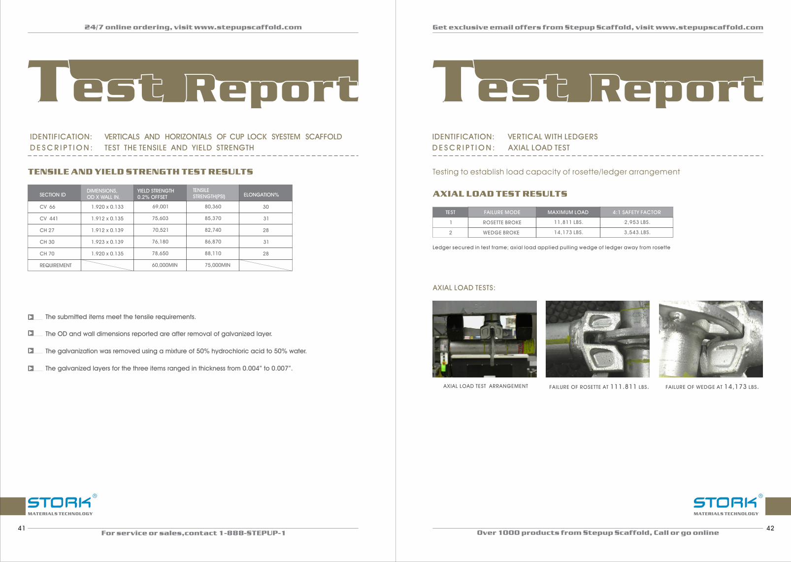
IDENTIFICATION: VERTICAL WITH LEDGERS
D E S C R I P T I O N : AXIAL LOAD TEST
Testing to establish load capacity of rosette/ledger arrangement
AXIAL LOAD TEST RESULTSAXIAL LOAD TEST RESULTS
TEST
1
2
FAILURE MODE
ROSETTE BROKE
WEDGE BROKE
MAXIMUM LOAD
11,811 LBS.
14,173 LBS.
4:1 SAFETY FACTOR
2,953 LBS.
3,543.LBS.
Ledger secured in test frame; axial load applied pulling wedge of ledger away from rosette
AXIAL LOAD TESTS:
AXIAL LOAD TEST ARRANGEMENT FAILURE OF ROSETTE AT 111.811 LBS. FAILURE OF WEDGE AT 14,173 LBS.
R
MATERIALS TECHNOLOGY
R
MATERIALS TECHNOLOGY
24/7 online ordering, visit www.stepupscaffold.com
For service or sales,contact 1-888-STEPUP-1
Get exclusive email offers from Stepup Scaffold, visit www.stepupscaffold.com
Over 1000 products from Stepup Scaffold, Call or go online41 42
Test ReportTest ReportTest ReportTest ReportIDENTIFICATION: VERTICALS AND HORIZONTALS OF CUP LOCK SYESTEM SCAFFOLD
D E S C R I P T I O N : TEST THE TENSILE AND YIELD STRENGTH
TENSILE AND YIELD STRENGTH TEST RESULTSTENSILE AND YIELD STRENGTH TEST RESULTS
DIMENSIONS,OD X WALL IN.
YIELD STRENGTH0.2% OFFSET
TENSILESTRENGTH(PSI) ELONGATION%
1.920 x 0.133
1.912 x 0.135
1.912 x 0.139
1.923 x 0.139
1.920 x 0.135
69,001
75,603
70,521
76,180
78,650
80,360
85,370
82,740
86,870
88,110
60,000MIN 75,000MIN
30
31
28
31
28
SECTION ID
CV 66
CV 441
CH 27
CH 30
CH 70
REQUIREMENT
The submitted items meet the tensile requirements.
The OD and wall dimensions reported are after removal of galvanized layer.
The galvanization was removed using a mixture of 50% hydrochloric acid to 50% water.
The galvanized layers for the three items ranged in thickness from 0.004” to 0.007”.

IDENTIFICATION: VERTICAL WITH LEDGERS
D E S C R I P T I O N : DOUBLE SHEAR CAPACITY LOAD TEST
DOUBLE SHEAR CAPACITY LOAD TEST RESULTSDOUBLE SHEAR CAPACITY LOAD TEST RESULTS
Loads applied 12” from wedge center, simultaneously on two ledgers.Ledgers secured at both ends between verticals.
TEST
1
FAILURE MODE
ROSETTE DEFLECTION
MAXIMUM LOAD
9,700 LBS.
4:1 SAFETY FACTOR
2,425 LBS.
DOUBLE VERTICAL LOAD TEST:
DEFLECTION OF ROSETTES AT 9,700 LBS. TEST ARRANGEMENT
R
MATERIALS TECHNOLOGY
R
MATERIALS TECHNOLOGY
24/7 online ordering, visit www.stepupscaffold.com
For service or sales,contact 1-888-STEPUP-1
Get exclusive email offers from Stepup Scaffold, visit www.stepupscaffold.com
Over 1000 products from Stepup Scaffold, Call or go online43 44
Test ReportTest ReportTest ReportTest ReportIDENTIFICATION: VERTICAL WITH LEDGERS
D E S C R I P T I O N : VERTICAL SHEAR LOAD TEST
Testing to establish load capacity of rosette/ledger arrangement
VERTICAL SHEAR LOAD TEST RESULTSVERTICAL SHEAR LOAD TEST RESULTS
TEST
1
2
FAILURE MODE
ROSETTE CRACKED
MAXIMUM LOAD
11,000 LBS.
11,500 LBS.
4:1 SAFETY FACTOR
2,750 LBS.
2,875 LBS.ROSETTE CRACKED
Load applied vertically near one wedge of ledger secured between two vertical members.
VERTICAL DOWNWARD SHEAR LOAD TESTS:
1 2 3
4
TEST ARRANGEMENT
ROSETTE DEFLECTION AT 11,000 LBS.
CRACK IN ROSETTE, TEST#2 AT 11,500 LBS.
CRACK IN ROSETTE, TEST#1 AT 11,000 LBS.
1
2
3
4

IDENTIFICATION: MF5H-5W-L3
D E S C R I P T I O N : MASON FRAME 60"H×60"W WITH DROP- LOCK
CHEMICAL ANALYSISCHEMICAL ANALYSIS
Q345E AISI 1513
ELEMENT RESULT% MIN% MAX% MIN% MAX%
C
MN
P
S
=
=
=
=
0.12
0.18
0.016
0.016
1.00
0.18
1.60
0.025
0.025
0.10
1.10
0.000
0.000
0.16
1.40
0.040
0.050
The leg of frame MF5H-5W-L3 meets Chinese steel Q345 Grades A, B, D, and E.It also meets a comparable US carbon steel, AISI 1513, referenced in ASTM A29.
TENSILE TEST RESULTSTENSILE TEST RESULTS (TEST METHOD:ASTM A370/ASTM E8)
SPECIMEN DIMENSIONS, OD X WALL, IN.
AREA,SP.INS.YIELD STRENGTH, [email protected]% OFFSET
TOTAL LOAD, LBS. TENSILE STRENGTH, PSI %EI,(2”)
Tensile test performed on vertical mason frame leg
1.7000x0.093 0.470 63,300 34.814 74,100 31
REQUIREMENT 60,000 MIN 70,000 MIN
SCAFFOLD FRAME LOAD TEST RESULTS (MF5H-5W-L3)
Set #1
Set #2
LOAD AT YIELD(LBS)
LOAD PER LEG AT YIELD (LBS)
4:1 SAFETY FACTOR PER LEG,BASED ON YIELD (LBS)
71,450
75,200
17,865
18,800
4,465
4,700
SET #1 PICTURED SET #2 PICTURED
AT YIELD OF 75,200 LBS.AT 51,450 LBS.AT YIELD OF 71,450 LBS.AT 51,450 LBS.
R
MATERIALS TECHNOLOGY
R
MATERIALS TECHNOLOGY
24/7 online ordering, visit www.stepupscaffold.com
For service or sales,contact 1-888-STEPUP-1
Get exclusive email offers from Stepup Scaffold, visit www.stepupscaffold.com
Over 1000 products from Stepup Scaffold, Call or go online45 46
Test ReportTest ReportTest ReportTest ReportIDENTIFICATION: SCAFFOLD PLANK
D E S C R I P T I O N : STEEL PLANK GALV.WITH HOOKS
SCAFFOLD PLANK LOAD TESTING COMPONENTS PROVIDED BY SUNSHINE ENTERPRISESSCAFFOLD PLANK LOAD TESTING COMPONENTS PROVIDED BY SUNSHINE ENTERPRISES
PLANK LOAD TYPEMAXIMUM LOAD(LBS)*
S-SP3(3FT)
LOAD DIVIDED BY SAFETY FACTOR OF 4
CALCULATED LBS/FT.LOAD, (LOAD/LENGTH)
REQUIREMENT(LBS/FT)
S-SP5(5FT)
POINT LOAD
UNIFORM LOAD
4,938
5,276
1,235
1,319
412
264 213
MAXIMUM LOAD TOTALS INCLUDE THE WEIGHT OF ANY BEAM(S) USED:
1 2 3
4
Uniform load applied on 14-3/16” centers. Center of support roller to center of first ram=14-3/16”center of first ram to center of second ram-14-3/16”, etc. The load of 5,276 lbs. Includes the 70# weight of the beam used to apply load across the rams.
The rams were placed on 4”x9” plates. The load was applied through the instron load cell, seen at top center of photograph.
CONFIGURATION FOR POINT LOAD
SSP5-UNIFORM LOAD CONFIGURATION
SSP3 AFTER POINT LOAD OF 4,868 LBS.
SSP5 AFTER UNIFORM LOAD OF 5,276 LBS.
1
2
3
4
S SP7(7FT)-
S SP10(10FT)-
UNIFORM LOAD 2,528 632 120 75
UNIFORM LOAD 2,260 565 74.83 50

IDENTIFICATION: 7’ X 6’ WALK THRU FRAME
D E S C R I P T I O N : CANOPY FRAME LOAD TEST
TF7H-6W-L5. 6”
R
MATERIALS TECHNOLOGY
R
MATERIALS TECHNOLOGY
24/7 online ordering, visit www.stepupscaffold.com
For service or sales,contact 1-888-STEPUP-1
Get exclusive email offers from Stepup Scaffold, visit www.stepupscaffold.com
Over 1000 products from Stepup Scaffold, Call or go online47 48
Test ReportTest ReportTest ReportTest Report
1
TOWER TEST #
2
3
4
AVERAGE
YIELD LOAD (LBS) LOAD PER LEG (LBS)LOAD PER LEG (LBS)AT 4:1 SAFETY FACTOR
DEVIATION FROMAVERAGE
33,400
31.190
30.085
31.190
31.470
8.350
7.800
7,520
7,800
7,870
2,090
1,950
1,880
1,950
1,970
6.1%
0 8. %
4 4. %
0 8. %
The towers have been tested in accordance with CAN/CSA-S269,2-M87, except that screw jack extension at topand bottom were set at 6”, per CAN/CSA-S269.2-M87, a dviation from the average of 15% is permissible.
1 2 3 4 5
1.
2.
3.
4.
REPRESENTATIVE PRE-LOAD CONDITION
TEST#1.DEFLECTION AT 33,400 LBS
TEST#2.DEFLECTION AT 31,190 LBS
TEST#3.DEFLECTION AT 30,085 LBS
5. TEST#4.DEFLECTION AT 31,190 LBS
IDENTIFICATION: TF6H-42W-L3
D E S C R I P T I O N : THROUGH FRAME 76" H ×42"W WITH DROP - LOCK
CHEMICLA ANALYSISCHEMICLA ANALYSIS
Q345E AISI 1513
ELEMENT RESULT% MIN% MAX% MIN% MAX%
C
MN
P
S
====
0.14
0.17
0.018
0.018
1.00
0.18
1.60
0.025
0.025
0.10
1.10
0.000
0.000
0.16
1.40
0.040
0.050
The leg of frame TF6H-42W-L3 meets Chinese steel Q345 Grades A, B, D, and E.It also meets a comparable US carbon steel, AISI 1513, referenced in ASTM A29.
TENSILE TEST RESULTSTENSILE TEST RESULTS (TEST METHOD: ASTM A370/ASTM E8)
SPECIMEN DIMENSIONS,OD X WALL, IN.
AREA SQ. LNS.
YIELD STRENGTH, [email protected]% OFFSET
TOTAL LOAD, LBS.
TENSILE STRENGTH,PSI
%E1,(2”)
1.700x0.093 0.470 61,900 33,593 71,500 24
Requirement 60,000 min 70,000 min
Tensile test performed on vertical through frame leg
SAFFOLD FRAME LOAD TEST RESULTS TF6H-42WSAFFOLD FRAME LOAD TEST RESULTS TF6H-42W
4:1 SAFETY FACTOR PER LEG,BASED ON YIELD (LBS)
LOAD AT YIELD(LBS)
LOAD PER LEGAT YIELD (LBS)
SET #1
Set #2
73,950
68,000
18,488
17,000
4,622
4,250
SET #1 PICTURED SET #2 PICTURED
AT 51,450 LBS. AT 56,450 LBS.AT YIELD OF 73,950 LBS. AT YIELD OF 68,000 LBS.

R
MATERIALS TECHNOLOGY
R
MATERIALS TECHNOLOGY
24/7 online ordering, visit www.stepupscaffold.com
For service or sales,contact 1-888-STEPUP-1
Get exclusive email offers from Stepup Scaffold, visit www.stepupscaffold.com
Over 1000 products from Stepup Scaffold, Call or go online49 50
Test ReportTest ReportTest ReportTest ReportIDENTIFICATION: SB-20-HH-H
D E S C R I P T I O N : 20" SIDE BRACKET W/ HOOK HANGER FOR HOUSTON
CHEMICAL ANALYSISCHEMICAL ANALYSIS
Q215 A,B Q235 A AISL 1015
ELEMENT
C
MN
P
S
====
0.14
0.38
0.015
0.016
0.09
0.25
0.15
0.55
0.045
0.045
0.80
0.16
1.50
0.045
0.045
0.13
0.30
0.000
0.000
0.18
0.60
0.040
0.050
TENSILE TEST RESULTSTENSILE TEST RESULTS
SPECIMEN DIMENSIONS,OD X WALL, IN.
AREA SQ. LNS.
YIELD STRENGTH, [email protected]% OFFSET
TOTAL LOAD, LBS.
TENSILE STRENGTH,PSI
%E1,(2”)
1.066x0.073
REQUIREMENT
0.228 80.200
60.000 MIN.
19.241 84.400
70,000 MIN.
10
LOAD TEST RESULTSLOAD TEST RESULTS
(TEST METHOD: ASTM A370/ASTM E8)
LOAD WITH 4:1 SAFETY FACTOR (LBS)
FAILURE MODE YIELD LOAD (LBS)TEST SAMPLE#
1
2
DEFORMATION OF HOOK
DEFORMATION OF HOOK
3,000
3,350
750
838
1 2 3 4 5
CONFIGURATION FOR TESTING SIDE BRACKETS.
TEST SET-UP FOR SB20-HH-H TYPE BRACKET PHOTO TAKEN AT LOAD OF 2,900 LBS.
SB20-HH-H #1 AT LOAD OF 3,000 LBS.
SB20-HH-H #1 AT LOAD OF 3,000 LBS.
SB20-HH-H #2 AT LOAD OF 3,350 LBS.
1.
2.
3.
4.
5.
RESULT% MIN% MAX% MIN% MAX% MIN% MAX%
IDENTIFICATION: 6 5 3 6’4 X 5’ WALK THRU FRAME
D E S C R I P T I O N : 1.69” TUBE WALK THROUGH FRAME LOAD TEST
TF H- W-L . ”
1
TOWER TEST #
2
3
4
AVERAGE
YIELD LOAD (LBS) LOAD PER LEG (LBS)LOAD PER LEG (LBS)AT 4:1 SAFETY FACTOR
DEVIATION FROMAVERAGE
39,970
42.160
39.970
43.255
41.340
9.990
10.540
9,990
10,810
10,330
2,500
2,640
2,500
2,700
2,590
3.3%
1 9. %
3 3. %
4 6. %
The towers have been tested in accordance with CAN/CSA-S269,2-M87, except that screw jack extension at topand bottom were set at 6”, per CAN/CSA-S269.2-M87, a dviation from the average of 15% is permissible.
1 2 3 4 5
1.
2.
3.
4.
REPRESENTATIVE PRE-LOAD CONDITION
TEST#1.DEFLECTION AT 39,970 LBS
TEST#2.DEFLECTION AT 42,160 LBS
TEST#3.DEFLECTION AT 39,970 LBS
5. TEST#4.DEFLECTION AT 43,255 LBS

R
MATERIALS TECHNOLOGY
R
MATERIALS TECHNOLOGY
24/7 online ordering, visit www.stepupscaffold.com
For service or sales,contact 1-888-STEPUP-1
Get exclusive email offers from Stepup Scaffold, visit www.stepupscaffold.com
Over 1000 products from Stepup Scaffold, Call or go online51 52
Test ReportTest ReportTest ReportTest ReportIDENTIFICATION: SJ1P
D E S C R I P T I O N : GALVANIZED SCREW JACKS WITH 5-1/2" BASE PLATES.
COMPRESSIVE LOAD TEST RESULTSCOMPRESSIVE LOAD TEST RESULTS
EXTENSION HEIGHT
6”
12”
18”
45,900
42,200
39,800
Screw jack at 6”extension at yield load of 45,900 lbs.
IDENTIFICATION: SJ1S
D E S C R I P T I O N : GALVANIZED SCREW JACKS WITH SOCKET
LOAD TEST RESULTSLOAD TEST RESULTS
EXTENSIONMAXIMUM LOADAT YIELD (LBS)
4:1 SAFETY FACTOR, BASED ON YIELD (LBS)
FAILURE MODE
NONE
MID EXTENSION 15" FROM BASE PLATE TO JACK HANDLE
MAX EXTENSION 23" FROM BASE PLATE TO JACK HANDLE
27,900
31,450
31,700
6,975
7,863
7,925
SOCKET TUBE COMPRESSION AND JACK DEFORMATION
SOCKET TUBE COMPRESSION AND JACK DEFORMATION
SOCKET TUBE COMPRESSION AND JACK DEFORMATION
Test configuration with no extension.
Mid extension, yield load of 31,450 lbs.
No extension, yield load of 27,900 lbs.
Max extension, yield load of 31,700 lbs.
Lower compressive strength value for jack with no extension is due to direct loading of screw jack handle onto socket tube weld.
LOAD AT (LBS.)YIELD WITH 4:1 SAFETY FACTORLOAD AT (LBS.)YIELD
11,475
10,550
9,950
Screw jack at 12”extension at yield load of 42,200 lbs.
Screw jack at 18”extension at yield load of 39,800 lbs.

24/7 online ordering, visit www.stepupscaffold.com
For service or sales,contact 1-888-STEPUP-1
Get exclusive email offers from Stepup Scaffold, visit www.stepupscaffold.com
Over 1000 products from Stepup Scaffold, Call or go online53 54
Test ReportTest ReportTest ReportTest ReportIDENTIFICATION: 12” CASTERS
D E S C R I P T I O N : SYS TEM SCAFFOLD CASTER LOAD TES T
TEST #
1
TORQUE AT WHICH WHEEL ROTATEDCLOCKWISE DIRECTION
TORQUE AT WHICH WHEEL ROTATEDCOUNTER CLOCKWISE DIRECTION
58.2 LBS 78.8 LBS
CASTER WHEEL ULTIMATE LOAD TEST WITH 5°OFFSET AS PRESCRIBED IN ANSL/SSFI SC 100-5/05,SECTION 5.6.5CASTER WHEEL ULTIMATE LOAD TEST WITH 5°OFFSET AS PRESCRIBED IN ANSL/SSFI SC 100-5/05,SECTION 5.6.5
TEST #
1
ULTIMATE LOAD
13808 LBS
LOAD APPLICATION AT 5°AXIAL OFFSET TYPICAL STEM DEFLECTION FAILURE FOR EACH CASTER
IDENTIFICATION: NETTING
D E S C R I P T I O N : NFPA 701 METHOD 2 TEST
LEACH TEST RESULTSLEACH TEST RESULTS
SPECIMENDIMENSIONS
(INCHES)CHAR LENGTH
(INCHES)AFTERBURN(SECONDS)
FLAMING RESIDUE(SECONDS)
1
2
3
4
25 X 47
25 X 47
25 X 47
25 X 47
10.5
7.8
9.3
11.0
0.0
0.0
0.0
0.0
0.0
0.0
0.0
0.0
The time of individual specimen continues flaming was not more than 2 seconds after the test flame is removed from contact with the specimen.
The length of char of individual folded specimen does not exceed 1050 mm (41.3in) .
The time of portions or residues continues flaming was not more than 2 seconds.
Passed NFPA 701 method 2 fire retardant standard
CASTER WHEEL BRAKE TORQUE TEST ANSI/SSFI SC 100-5/05, SECTION 5.6CASTER WHEEL BRAKE TORQUE TEST ANSI/SSFI SC 100-5/05, SECTION 5.6

R
MATERIALS TECHNOLOGY
24/7 online ordering, visit www.stepupscaffold.com
For service or sales,contact 1-888-STEPUP-1
Get exclusive email offers from Stepup Scaffold, visit www.stepupscaffold.com
Over 1000 products from Stepup Scaffold, Call or go online55 56
Test ReportTest ReportTest ReportTest Report
TOWER TEST #DEVIATION FROM AVERAGE
LOAD PER LEG (LBS)LOAD PER LEG (LBS)AT 4:1 SAFETY FACTOR
1
2
3
4
AVERAGE
58,030
64,870
60,310
66,010
62,305
6.9%
4.1%
3.2%
5.9%
14,505
16,215
15,075
16,500
15,570
3,625
4,050
3,765
4,125
3,890
The towers have been tested in accordance with CAN/CSA-S269.2-M87 and ANSI/SSFI SC-100/5-05
IDENTIFICATION:
D E S C R I P T I O N : 3 TIER SYSTEM SCAFFOLD LOAD TEST
SYSTEM SCAFFOLD
Our letters and reports are for the exclusive use of the client to whom they are addressed and shall not be
reproduced except in full without the approval of the testing laboratory. The use of our name must receive our
written approval. Our letters and reports apply only to the sample tested and/or inspected, and are not
indicative of the quantities of apparently identical or similar products. Material submitted to our metals
department will be discarded after a period of 30 days unless otherwise directed. Stork SWL, is an operating
unit of Stork Materials Technology B.V., Amsterdam, The Netherlands, which is a member of the Stork group.
1 2
FULLY CONSTRUCTED SYSTEM SCAFFOLD
REPRESENTATIVE LEG FAILURE
1.
2.
R
MATERIALS TECHNOLOGY
IDENTIFICATION: TF7H-6W-L5. 7’6” X 6” WALK THRU FRAME
D E S C R I P T I O N : FRAME SCAFFOLD 3-TIER LOAD TEST
TOWER TEST # YIELD LOAD (LBS) YIELD LOAD (LBS)LOAD PER LEG (LBS)DEVIATION FROM AVERAGE
LOAD PER LEG (LBS)AT 4:1 SAFETY FACTOR
1
2
3
4
AVERAGE
33,400
31,190
30,085
31,190
31,470
8,350
7,800
7,520
7,800
7,870
2,090
1,950
1,880
1,950
1,970
6.1%
0 8. %
4 4. %
0 8. %
The towers have been tested in accordance with CAN/CSA-S269.2-M87,except that screw jack extensions at top and bottom were set at 6”. Per CAN/CSA-S269.2-M87, a deviation from the average of 15% is permissible.
1 2 3 4
1.
2.
3.
4.
TEST#1.DEFLECTION AT 33,400 LBS
TEST#2.DEFLECTION AT 31,190 LBS
TEST#3.DEFLECTION AT 30,085 LBS
TEST#4.DEFLECTION AT 31,190 LBS

24/7 online ordering, visit www.stepupscaffold.com
For service or sales,contact 1-888-STEPUP-1
Get exclusive email offers from Stepup Scaffold, visit www.stepupscaffold.com
Over 1000 products from Stepup Scaffold, Call or go online57 58
Test ReportTest ReportTest ReportTest Report
RIGHT ANGLE # 1. ULTIMATE LOAD OF 14,580 LBS.
RIGHT ANGLE # 2, ULTIMATE LOAD OF 15,150 LBS. RIGHT ANGLE # 2, DEFORMATION OF PIVOT PIN, AND FORGING AROUND PIVOT PIN
R
MATERIALS TECHNOLOGY
R
MATERIALS TECHNOLOGY
IDENTIFICATION: CLAMP-R
D E S C R I P T I O N : EN74 TEST
ELEMENT
CHEMICAL ANALYSISCHEMICAL ANALYSIS
C
MN
P
S
=
=
=
=
RESULT% MIN% MAX% MIN% MAX%
Q255,GRADE A AISI 1020
0.18
0.44
0.010
0.018
0.14
0.30
0.000
0.000
0.22
0.65
0.045
0.050
0.18
0.30
0.000
0.000
0.23
0.60
0.040
0.050
The material from Clamp – R meets Chinese steel Q255, Grade A. It also meets comparable US steel, AISI 1020
SLIP LOADSLIP LOAD
COUPLER # SLIP LOAD (MEASURED AFTER 0.275” TRAVEL)
1
2
AVERAGE
8,565 LBS.
5,124 LBS.
6,845 LBS.
With 4:1 safety factor, the average slip load value is 1,711 lbs.
ULTIMATE LOADULTIMATE LOAD
COUPLER #
1
2
AVERAGE
ULTIMATE LOAD FAILURE MODE
14,580 LBS.
15,150 LBS.
14,865 LBS.
DEFORMATION OF PIVOT PIN
DEFORMATION OF PIVOT PIN
With 4:1 safety factor, the average ultimate load value is 3,716 lbs.
Hexagonal head of clamp bolts are tightened to 38 ft. Lbs.Prior to loading for all tests. SLIP LOAD
Our letters and reports are for the exclusive use of the client to whom they are addressed and shall not be
reproduced except in full without the approval of the testing laboratory. The use of our name must receive our
written approval. Our letters and reports apply only to the sample tested and/or inspected, and are not
indicative of the quantities of apparently identical or similar products. Material submitted to our metals
department will be discarded after a period of 30 days unless otherwise directed.
IDENTIFICATION: CLAMP-R
D E S C R I P T I O N : EN74 TEST (CONTINUE FROM PAGE 59)
RIGHT ANGLE COUPLER TEST CONFIGURATION

1-1/2” 1-5/8” 1-11/16”
1-7/16”1-3/8”1-1/4”
There are 3 kinds of tube
size and 3 kinds of
coupling pins fitting with
different tube sizes
W LOCK
FLIP LOCK
DRIP LOCK
SNAP- ON LOCK
V LOCK
BJ LOCK
CANADIAN LOCK
(L1) (L2) (L3) (L4 )
(L5) (L6) (L7)
(L1)
(L7)
(L2)
(L3)
(L4)
(L5)
(L6)
24/7 online ordering, visit www.stepupscaffold.com
For service or sales,contact 1-888-STEPUP-159
Customize options
NotesAll measurements, drawings and illustrations used in this catalog are for information purposes. Stepup Scaffold and its suppliers make no representation about the suitability, accuracy, or completeness of the information contained in this document for any other purposes, including, not limiting to, availability, safety data, warranty, and terms of sale.
In no event shall Stepup Scaffold or its suppliers be liable for any special, indirect, consequential or exemplary damages or any damages whatsoever resulting from loss of use, data or profit arise out of or related to the use of information available from this document.
Changes are periodically made to the information in the document. Stepup Scaffold reserves the right to make improvements or changes to the content of this document at anytime without notice.
Copyright @ 2012 Stepup Scaffold. All rights Reserved. [email protected].
Not to be reproduced in whole or parts without advanced permission. Misprints and errors excepted.
For service or sales,contact 1-888-STEPUP-1